WATERMAN VALVE HEAVY DUTY CAST IRON SLUICE / SLIDE …
28
WATERMAN VALVE Compliant with AWWA C560 Best-in-Class Construction for Long Life in Critical Applications HEAVY DUTY CAST IRON SLUICE / SLIDE GATES
Transcript of WATERMAN VALVE HEAVY DUTY CAST IRON SLUICE / SLIDE …

WATERMAN VALVE
Compliant with AWWA C560
Best-in-Class Construction for Long Life in Critical Applications
HEAVY DUTY CAST IRON SLUICE / SLIDE GATES

2
Product Summary ........................................................................................................................................................................................... 3
Self Contained vs. Non-Self Contained ............................................................................................................................................................ 4
Q-Seal Flushbottom Seal (Full Flow Opening) ................................................................................................................................................. 5
Resilient Seated (Gliding Seal) Option ............................................................................................................................................................ 5
Wedges ........................................................................................................................................................................................................... 6
Cast vs. Fabricated Gates, Which is Best? ...................................................................................................................................................... 7
Recommended Mounting ................................................................................................................................................................................ 8
How to Specify ................................................................................................................................................................................................ 10
Gate Dimensions and Specs. 6"-14" width ...................................................................................................................................................... 11
Gate Dimensions and Specs. 15"-20" width .................................................................................................................................................... 12
Gate Dimensions and Specs. 21"-27" width .................................................................................................................................................... 13
Gate Dimensions and Specs. 30"-35" width .................................................................................................................................................... 14
Gate Dimensions and Specs. 36"-39" width .................................................................................................................................................... 15
Gate Dimensions and Specs. 42" width .......................................................................................................................................................... 16
Gate Dimensions and Specs. 48" width .......................................................................................................................................................... 17
Gate Dimensions and Specs. 54"-60" width .................................................................................................................................................... 18
Gate Dimensions and Specs. 66"-78" width .................................................................................................................................................... 19
Gate Dimensions and Specs. 84"-96" width .................................................................................................................................................... 20
Gate Dimensions and Specs. 102"-144" width ................................................................................................................................................ 21
Gate Dimensions and Specs. Metric Sizes ...................................................................................................................................................... 22
Typical Specifications ...................................................................................................................................................................................... 23 - 28
TABLE OF CONTENTS
For the latest digital copies of all Waterman specifications and drawings, visit our website at www.WatermanUSA.com

3
CAST IRON SLUICE / SLIDE GATES OVERVIEW
Waterman Cast Sluice Gates are used in applications where safety and reliable performance are essential (dams, tidal environments, water treatment plants) and where outstanding product longevity is desired. Waterman cast gates are preferred for high-head (up to 200') and high debris environments as well as for critical gateways in treatment plants.
Key Features:
• Thick, highly rigid frame and cover to handle high heads and environments with floating debris. Cover and frame design fully tested to meet or exceed design specifications with finite element analysis. Stress, deflection, and vibration are measured based on both seating and unseating heads and other external loading. Analysis allows gate to perform with maximum reliability and minimum leakage.
• Proven design as one of the industry’s oldest manufacturers of cast iron sluice gates, Waterman has thousands in operation worldwide.
• Low leakage machined metallic seating surfaces create a reliable tight seal, minimizing leakage. Seating faces are corrosion-resistant and are mechanically locked into the gate frame and cover in full-width dovetail grooves. Seats are made of a malleable material that is formed into the grooves. The fullwidth dovetail design prevents the possibility of leakage between the seat material and the castings.
• High performance adjustable wedge system offers easier maintenance and proven performance. Assures proper reliable closure of top, bottom and sides. (Bottom wedges not required with Q-Seal Flushbottom Seal)
• Choice of cast iron, ductile iron, 2% Ni and Ni-Resist cast iron alloys
• Design flexibility with the industry’s largest selection of sizes and mounting options: gate shapes available in square and rectangular, with square, rectangular or round openings to meet the needs of even the most unusual applications.
• Offered for a full range of mounting options: gates offered for submerged service, wall mounting, flange mount and more.

4
Gate Designs Available:
Most gate sizes are available as self-contained gates where the operating device is mounted on the top yoke of the gate. Operating loads are carried by the gate frame. The thrust required to open the gate is transmitted by the yoke and guides to the gate frame, unlike non-self-contained gates where these loads are carried by the structure above the gate where the floor stand is mounted. The self-contained design is used where the space above the gate is minimal and/or where structural supports limit the option of using a separate floor stand.
Non-self-contained gates separate the frame and guides from the operating floor stand. Often a crank-operated floor stand with a geared head is used to support the opening and closing thrust loads. These gates can also be fitted with motor and hydraulic actuators. Stem lengths can be varied to the application and are supported as needed by adjustable stem guides.
NON-SELF CONTAINED
OPERATOR
STEM
STEM GUIDE
PEDESTAL
TOP OF WALL BRACKET
YOKESTEM
OPERATOR
SELF CONTAINED
NON-SELF CONTAINED
OPERATOR
STEM
STEM GUIDE
PEDESTAL
TOP OF WALL BRACKET
YOKESTEM
OPERATOR
SELF CONTAINED

5
SPECIAL OPTIONS
Q-Seal™ Flushbottom Seal is available for applications where a full, continuous opening area without obstructions to impede solids is desirable. Typical applications include wastewater settling tanks, aeration tanks, sedimentation and flocculation basis.
The flushbottom closure features a continouous neoprene seal contained in the invert of the frame, providing a flat plane across the bottom of the gate without projections into the opening. The seal is firmly supported on three sides, exposing only the flat top side, minimizing the chance for damage. When a flushbottom seal is used, a smooth rounded projection is used on the bottom of the slide. When this compresses against the flushbottom Q-Seal, it makes a watertight closure.
1. On competitor units, raised seat wall traps debris
2. Or, recessed pocket seat traps debris
3. Q-Seal creates flow-through opening, no debris
1 2 3Why Choose Q-Seal™ Option:
Resilient Seated (Gliding Seal) Gates
High Performance Resilient Gliding Seal Gates are used in applications where extremely low leakage is required. The key difference from a traditional cast iron gate is in the seating materials (PVC and rubber seating surfaces instead of bronze) and tapered wedging action of the gate frame and seat.
Waterman Resilient Gliding Seal Gates offer a very low leakage rate equal to 1% of the AWWA C560 specified maximum allowable leakage (The net allowable leakage rate on a Resilient Seated Waterman Gate is 0.001 GPM per foot of perimeter).
Waterman resilient seated cast gates are preferred for applications with seating or unseating heads up to 25 feet. Each gate is custom built to your requirements.

6
High-performance wedges are used to insure tight contact between the bronze seating surfaces of the cover and the frame. As the gate moves, the wedges pull the top and bottom seats into contact.
Wedges are cast bronze and are precision machined and are designed for maximum adjustability and serviceability.
The side wedge system is the most critical portion of the design. It is designed to resist the vertical loads from gate operation and is designed to carry much of the unseating head load. The loads in the side wedge system can be high, so the right design is critical.
Waterman’s B and B-1 wedge systems place the adjustable portion of the side wedge on the slide and keys it in place, preventing twisting or rotation. The corrosion resistant fasteners allow for long life and also for field-replacement of damaged wedges. The performance of the wedge system is modeled with finite element analysis to assure an even load distribution.
Top and bottom wedges (where applicable) are fully-adjustable units that are easily set and locked into place with corrosion-resistant fasteners. They use a bronze hook-and-loop design and are also keyed in place to prevent movement under force.
SIDE WEDGES
TOP WEDGES
BOTTOM WEDGES
FRAMEWEDGE
DISCWEDGE
FRAMEWEDGE
DISCWEDGE
DISCWEDGE
FRAMEWEDGE
ADJUSTINGHARDWARE
ADJUSTINGHARDWARE
ADJUSTINGHARDWARE
SIDE WEDGES
TOP WEDGES
BOTTOM WEDGES
FRAMEWEDGE
DISCWEDGE
FRAMEWEDGE
DISCWEDGE
DISCWEDGE
FRAMEWEDGE
ADJUSTINGHARDWARE
ADJUSTINGHARDWARE
ADJUSTINGHARDWARE
SIDE WEDGES
TOP WEDGES
BOTTOM WEDGES
FRAMEWEDGE
DISCWEDGE
FRAMEWEDGE
DISCWEDGE
DISCWEDGE
FRAMEWEDGE
ADJUSTINGHARDWARE
ADJUSTINGHARDWARE
ADJUSTINGHARDWARE
SIDE WEDGE SYSTEM
TOP AND BOTTOM WEDGE SYSTEM
THE WATERMAN ADJUSTABLE WEDGE SYSTEM

7
WHAT TYPE OF GATE WORKS BEST FOR THE APPLICATION?Cast iron or ductile iron gates are known for providing long life in critical applications, particularly in installations where large dimensions are required or where higher heads are required.
This chart illustrates the wide range of applications for our cast gates, and notes applications where a specialty gate might be required. Please contact our applications support team for guidance in gate selection for your specific requirements.
Gate Selection Guide by Head and Size
Head
80’ Fabricated Cast Fabricated Cast Cast Cast Cast Cast Specialty or Roller
70’ Fabricated Cast Fabricated Cast Cast Cast Cast Cast Specialty or Roller
60’ Fabricated Cast Fabricated Cast Cast Cast Cast Cast
50’ Fabricated Cast Fabricated Cast Fabricated Cast Cast Cast Cast
40’ Fabricated Cast Fabricated Cast Fabricated Cast Fabricated Cast Fabricated Cast Fabricated Cast
30’ Fabricated Cast Fabricated Cast Fabricated Cast Fabricated Cast Fabricated Cast Fabricated Cast
20’ Fabricated Cast Fabricated Cast Fabricated Cast Fabricated Cast Fabricated Cast Fabricated Cast
10’ Fabricated Cast Fabricated Cast Fabricated Cast Fabricated Cast Fabricated Cast Fabricated Cast
Size 2' x 2' 4' x 4' 6' x 6' 8' x 8' 10' x 10' 12' x 12'
Fabricated Cast or Ductile Iron Specialty or Roller
8
WHY WALL THIMBLES ARE THE PREFERRED METHOD TO MOUNT A GATECast iron or ductile iron gates are known for providing long life in critical applications, particularly in installations where large dimensions are required or where higher heads are required.
This chart illustrates the wide range of applications for our cast gates, and notes applications where a specialty gate might be required. Please contact our applications support team for guidance in gate selection for your specific requirements.
KEY BENEFITS:• Pre-positions and aligns proper mounting location for gate. Provides a flat mounting surface.
• Eliminates time spent placing and drilling anchors – exact alignment occurs automatically with pre-drilled thimble holes. No errors or accidental deflection from improper anchor spacing.
• Provides an “engineered”, optimum anchor pattern with correct size and placement of anchors, critical in high head applications.
• Eliminates need for grouting behind gate – and potential for grout to foul gate seats.
• Creates proper opening during pour.
• Forms transition, where needed, from pipe on one side of wall with gate on other.
• Allows gate to be removed and reinstalled easily.
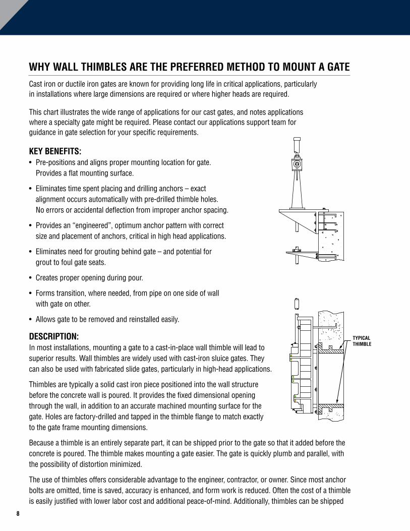
DESCRIPTION:In most installations, mounting a gate to a cast-in-place wall thimble will lead to superior results. Wall thimbles are widely used with cast-iron sluice gates. They can also be used with fabricated slide gates, particularly in high-head applications.
Thimbles are typically a solid cast iron piece positioned into the wall structure before the concrete wall is poured. It provides the fixed dimensional opening through the wall, in addition to an accurate machined mounting surface for the gate. Holes are factory-drilled and tapped in the thimble flange to match exactly to the gate frame mounting dimensions.
Because a thimble is an entirely separate part, it can be shipped prior to the gate so that it added before the concrete is poured. The thimble makes mounting a gate easier. The gate is quickly plumb and parallel, with the possibility of distortion minimized.
The use of thimbles offers considerable advantage to the engineer, contractor, or owner. Since most anchor bolts are omitted, time is saved, accuracy is enhanced, and form work is reduced. Often the cost of a thimble is easily justified with lower labor cost and additional peace-of-mind. Additionally, thimbles can be shipped
TYPICAL THIMBLE
9
early for inclusion in the construction forms, accelerating the job progress and eliminating the need for extra jobsite forming of the opening through the wall.
Overall construction costs may be reduced, installation time is lessened, a rigid machined surface is provided, and dependency upon the expertise of the installer is not as crucial. When a thimble is used, gates can be removed and installed again without disturbing the concrete. Future gate locations can also be planned with pre-installed thimbles matched to blind plates
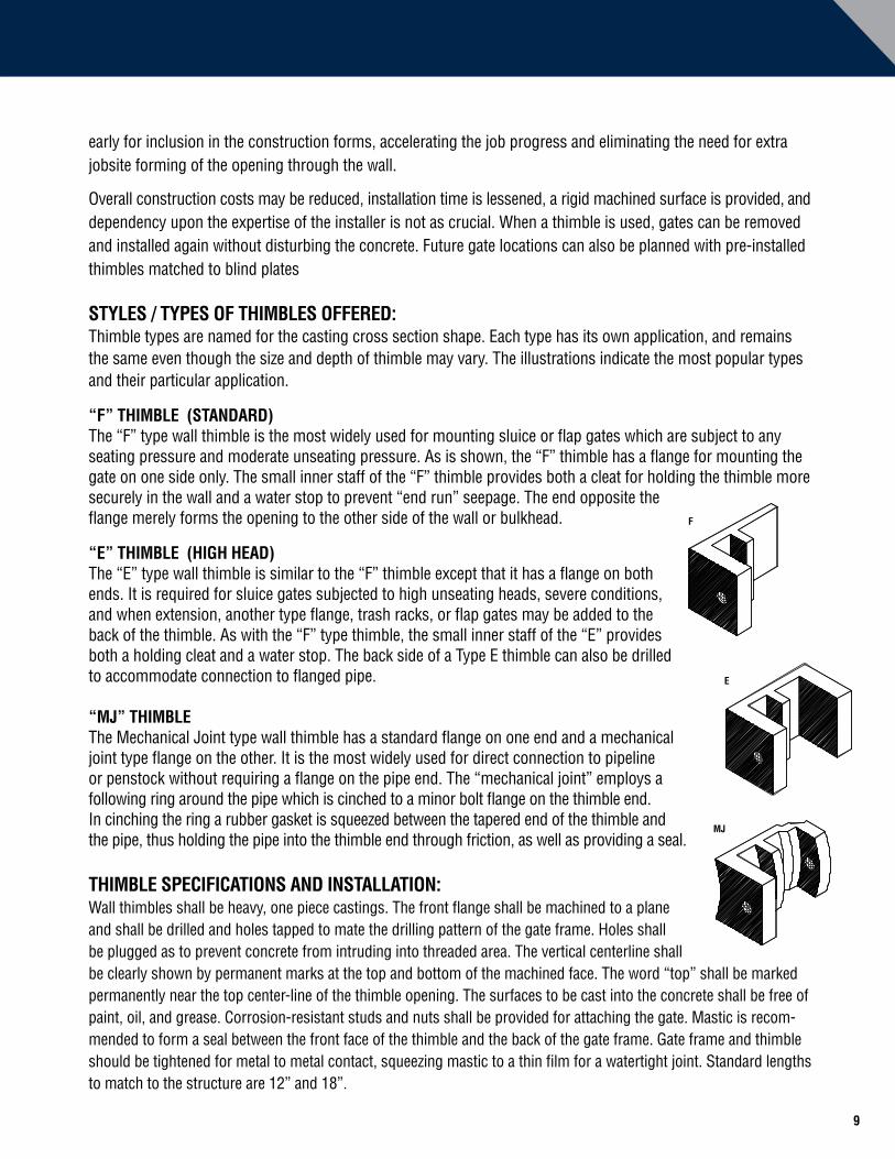
STYLES / TYPES OF THIMBLES OFFERED:Thimble types are named for the casting cross section shape. Each type has its own application, and remains the same even though the size and depth of thimble may vary. The illustrations indicate the most popular types and their particular application.
“F” THIMBLE (STANDARD)The “F” type wall thimble is the most widely used for mounting sluice or flap gates which are subject to any seating pressure and moderate unseating pressure. As is shown, the “F” thimble has a flange for mounting the gate on one side only. The small inner staff of the “F” thimble provides both a cleat for holding the thimble more securely in the wall and a water stop to prevent “end run” seepage. The end opposite the flange merely forms the opening to the other side of the wall or bulkhead.
“E” THIMBLE (HIGH HEAD)The “E” type wall thimble is similar to the “F” thimble except that it has a flange on both ends. It is required for sluice gates subjected to high unseating heads, severe conditions, and when extension, another type flange, trash racks, or flap gates may be added to the back of the thimble. As with the “F” type thimble, the small inner staff of the “E” provides both a holding cleat and a water stop. The back side of a Type E thimble can also be drilled to accommodate connection to flanged pipe.
“MJ” THIMBLEThe Mechanical Joint type wall thimble has a standard flange on one end and a mechanical joint type flange on the other. It is the most widely used for direct connection to pipeline or penstock without requiring a flange on the pipe end. The “mechanical joint” employs a following ring around the pipe which is cinched to a minor bolt flange on the thimble end. In cinching the ring a rubber gasket is squeezed between the tapered end of the thimble and the pipe, thus holding the pipe into the thimble end through friction, as well as providing a seal.
THIMBLE SPECIFICATIONS AND INSTALLATION:Wall thimbles shall be heavy, one piece castings. The front flange shall be machined to a plane and shall be drilled and holes tapped to mate the drilling pattern of the gate frame. Holes shall be plugged as to prevent concrete from intruding into threaded area. The vertical centerline shall be clearly shown by permanent marks at the top and bottom of the machined face. The word “top” shall be marked permanently near the top center-line of the thimble opening. The surfaces to be cast into the concrete shall be free of paint, oil, and grease. Corrosion-resistant studs and nuts shall be provided for attaching the gate. Mastic is recom-mended to form a seal between the front face of the thimble and the back of the gate frame. Gate frame and thimble should be tightened for metal to metal contact, squeezing mastic to a thin film for a watertight joint. Standard lengths to match to the structure are 12” and 18”.
F
E
MJ
BELL
F
E
MJ
BELL

10
HOW TO SPECIFY WATERMAN AWWA CAST IRON SLUICE / SLIDE GATESTo make it convenient for you to size and specify a Waterman Cast Iron Sluice / Slide Gate, we have provided charts of the standard available sizes and design head ratings available.
Multiple design head options are presented for different sizes to allow selection of the most effective and economical solution for your project.
If you have an application for a gate that is not met by the available sizes listed here, please contact us for additional information and practical solutions.
GENERAL SELECTION AND SPECIFICATION
Size:• The size of the gate (width and height) and the head rating (design and operating) are used to specify the gate required.
Design and Operating Head:• The design head shown in the tables is the maximum head that the gate has been engineered to withstand. Waterman’s engineers use tools such as Finite Element Analysis to verify the design.
• The operating head is the head under which the gate is to be opened and closed. The operating head is used to size the hoist mechanism and the stem requirement.
• Include both design and operating head in your specifications.
Installation Clearance:• The minimum installation clearance on sides and bottom shall be at least 1".
Notes:• Dimensions provided are for selection and are based on standard Waterman drawings. Waterman will furnish gates only for applications where the head is equal to or less than the design and operating heads indicated.

11
CAST GATE SIZES 6"-- 14"
F FFNON-SELF CONTAINED
CL
CL
F
G 1/4
OF STEM CL OF STEM
H 1/4
A
TO TOPOF DISCIN OPEN
POSITION
D
B
C
+_ +_
F FFNON-SELF CONTAINED
CL
CL
F
G 1/4
OF STEM CL OF STEM
H 1/4
A
TO TOPOF DISCIN OPEN
POSITION
D
B
C
+_ +_
SELF CONTAINED
A
B
C
TO TOPOF DISCIN OPEN
POSITION
D
E
CL
SELF CONTAINED
NON-SELF CONTAINED
F FF
NOTES:
* To top of fabricated yoke.
Seating and Unseating values are based on standard casting material, either Cast Iron ASTM A-126 CL. B or Ductile Iron, depending on model. Consult factory for details.
Class C Cast Iron, 2% Ni and Ni-Resist Available
SIZE DESIGN HEAD FT. (M) DIMENSIONS
WIDTH X HEIGHT INCHES
(MILLIMETERS)SEAT UNSEAT A B C D E F
G
± 1/4"
H
± 1/4"
6 x 6 (150 x 150)
276.8 (84)
81.6 (25)
11-1/8 (283)
6 (152)
7-1/2 (191)
13-1/8 (333)
13-5/8 (346)
4-3/4 (121)
2-1/4 (57)
4-3/4 (121)
6 x 6 (150 x 150)
600 (183)
60 (18)
15-3/4 (400)
6-1/2 (165)
10 (254)
15-5/16 (389)
17-1/4 (438)
6-3/4 (171)
4-1/16 (103)
7-1/2 (191)
6 x 6 (150 x 150)
618 (188)
233 (71)
15-1/2 (394)
6-1/2 (165)
9-13/16 (249)
14-3/4 (375)
16 (406)
8-1/2 (216)
4-1/2 (114)
7-1/2 (191)
8 x 8 (200 x 200)
151 (46)
67 (20)
18 (457)
8 (203)
10-3/16 (259)
15 (381)
21-1/2 (546)
8-1/2 (216)
4-1/2 (114)
7-1/2 (191)
8 x 8 (200 x 200)
240.0 (73)
86.5 (26)
13-1/8 (333)
7 (178)
9-1/2 (241)
16-1/8 (410)
16-5/8 (422)
4-3/4 (121)
2-1/4 (57)
4-3/4 (121)
8 x 8 (200 x 200)
575 (175)
210 (64)
18 (457)
8-1/2 (216)
10-9/16 (268)
18-1/4 (464)
20-7/16 (519)
6-13/16 (173)
4-1/8 (105)
7-1/2 (191)
10 x 10 (250 x 250)
173.8 (53)
66.5 (20)
15-1/8 (384)
8 (203)
11-1/2 (292)
19-1/8 (486)
19-5/8 (498)
4-3/4 (121)
2-1/4 (57)
4-3/4 (121)
10 x 10 (250 x 250)
475 (145)
45 (14)
20 (508)
9-1/2 (241)
12-1/2 (318)
21-1/4 (540)
23-3/8 (594)
6-13/16 (173)
4-3/16 (106)
8-1/2 (216)
10 x 10 (250 x 250)
586 (179)
99 (30)
20 (508)
9-1/2 (241)
12-1/8 (308)
18-1/8 (460)
24-1/2 (622)
9-1/2 (216)
5 (127)
8-1/2 (216)
12 x 12 (305 x 305)
139.0 (42)
40.3 (12)
17-1/2 (445)
9-1/4 (235)
13-1/2 (343)
22-18 (562)
22-15/16 (583)
5-7/8 (149)
3-1/4 (83)
5-7/8 (149)
12 x 12 (305 x 305)
450 (137)
50 (15)
22-1/4 (565)
10-1/2 (267)
14-1/2 (368)
24-5/8 (625)
29-1/8 (740)
7-1/16 (179)
4-9/16 (116)
8-1/2 (216)
12 x 12 (305 x 305)
456 (139)
144 (44)
22-1/4 (565)
10-1/2 (267)
14-1/4 (362)
21-1/4 (540)
27-3/8 (695)
9-1/2 (241)
5 (127)
8-1/2 (216)
12 x 18 (305 x 460)
155 (47)
50 (15)
22 (559)
13-1/2 (343)
20-3/4 (527)
30-3/8 (772)
36-3/8* (924*)
8-3/4 (222)
5-1/2 (140)
8-3/4 (222)
12 x 24 (305 x 610)
150 (46)
55 (17)
23-1/2 (597)
16-1/2 (419)
28-5/8 (727)
39 (991)
44 (1118)
11-1/2 (292)
7 (178)
11 (279)
14 x 14 (360 x 360)
149 (45)
35 (11)
24 (610)
11-1/2 (292)
16-1/8 (410)
24-1/4 (616)
30 (762)
9-1/2 (241)
5 (127)
8-1/2 (216)
14 x 14 (360 x 360)
255 (78)
43 (13)
24 (610)
11-1/2 (292)
16-5/8 (422)
27-13/16 (706)
31-11/16 (805)
7-3/4 (197)
4-11/16 (119)
8-1/2 (216)

12
CAST GATE SIZES 15"-- 20"
F FFNON-SELF CONTAINED
CL
CL
F
G 1/4
OF STEM CL OF STEM
H 1/4
A
TO TOPOF DISCIN OPEN
POSITION
D
B
C
+_ +_
F FFNON-SELF CONTAINED
CL
CL
F
G 1/4
OF STEM CL OF STEM
H 1/4
A
TO TOPOF DISCIN OPEN
POSITION
D
B
C
+_ +_
SELF CONTAINED
A
B
C
TO TOPOF DISCIN OPEN
POSITION
D
E
CL
SELF CONTAINED
NON-SELF CONTAINED
F FF
NOTES:
* To top of fabricated yoke.
Seating and Unseating values are based on standard casting material, either Cast Iron ASTM A-126 CL. B or Ductile Iron, depending on model. Consult factory for details.
Class C Cast Iron, 2% Ni and Ni-Resist Available
SIZE DESIGN HEAD FT. (M) DIMENSIONS
WIDTH X HEIGHT INCHES
(MILLIMETERS)SEAT UNSEAT A B C D E F
G
± 1/4"
H
± 1/4"
15 x 15 (380 x 380)
114 (35)
39 (12)
25-1/2 (648)
11-1/2 (292)
17 (432)
25-1/4 (641)
31-3/4 (806)
9-1/2 (241)
5 (127)
8-1/2 (216)
15 x 15 (380 x 380)
250 (76)
42 (13)
25 (635)
12 (305)
17-1/2 (445)
29-5/16 (745)
33-1/8 (841)
7-3/4 (197)
4-11/16 (119)
8-1/2 (216)
15 x 15 (380 x 380)
276.7 (84)
72.1 (22)
24 (610)
12 (305)
17 (432)
28-7/8 (733)
30-3/16 (767)
8-1/4 (210)
4-3/4 (121)
8-1/8 (206)
16 x 16 (410 x 410)
63 (19)
24 (7)
26-1/4 (667)
12-1/2 (318)
18 (457)
27-1/16 (687)
33-1/2 (851)
9-1/2 (241)
5 (127)
8-1/2 (216)
16 x 16 (410 x 410)
92.9 (28)
45.5 (14)
25 (635)
12-1/2 (318)
18-3/16 (462)
30-3/8 (772)
31-11/16 (805)
8-1/4 (210)
4-3/4 (121)
8-1/8 (206)
16 x 16 (410 x 410)
245 (75)
41 (12)
26 (660)
12-1/2 (318)
19 (483)
30-7/8 (784)
35 (889)
7-3/4 (197)
4-11/16 (119)
8-1/2 (216)
16 x 16 (410 x 410)
319 (97)
114 (35)
26-1/4 (667)
12-1/2 (318)
18 (457)
31 (787)
33-1/2 (851)
9-1/2 (241)
5 (127)
8-1/2 (216)
18 x 12 (460 x 305)
260 (79)
96 (29)
28-5/8 (727)
10 (254)
20-1/2 (521)
21-1/4 (540)
27-1/4* (692*)
9-1/4 (235)
4-3/4 (121)
8-1/2 (216)
18 x 18 (460 x 460)
81.4 (25)
35.4 (11)
27 (686)
13-1/2 (343)
20 (508)
33-3/8 (848)
34-11/16 (881)
8-1/4 (210)
4-3/4 (121)
8-1/2 (216)
18 x 18 (460 x 460)
198 (60)
48 (15)
28 (711)
13-1/2 (343)
21 (533)
33-3/4 (857)
37-3/4 (959)
7-3/4 (197)
4-11/16 (119)
10 (254)
18 x 18 (460 x 460)
263 (80)
85 (26)
29 (737)
13-1/2 (343)
20-3/4 (527)
30 (762)
37 (940)
11-1/2 (292)
6-1/4 (159)
10 (254)
18 x 18 (460 x 460)
302 (92)
115 (35)
29 (737)
13-1/2 (343)
20-3/4 (527)
34 (864)
37 (940)
11-1/2 (292)
6-1/2 (165)
10-3/4 (273)
18 x 24 (460 x 610)
221 (67)
62 (19)
28-3/4 (730)
16-3/4 (425)
26-1/2 (673)
39-1/4 (997)
45-1/4* (1149*)
11-1/2 (292)
7 (178)
11 (279)
18 x 30 (460 x 760)
396 (121)
103 (31)
29 (737)
19-3/4 (502)
37-1/2 (953)
48-1/4 (1226)
55 (1397)
12-1/2 (318)
7 (178)
11 (279)
18 x 36 (460 x 910)
308 (94)
95 (29)
29 (737)
22-1/2 (572)
38 (965)
58-1/4 (1480)
63-5/8 (1616)
12-1/2 (318)
7 (178)
11 (279)
20 x 20 (510 x 510)
141.9 (43)
26.7 (8)
29 (737)
14-1/2 (368)
22 (559)
36-3/8 (924)
38-1/16 (967)
8-1/4 (210)
4-3/4 (121)
8-1/8 (206)
20 x 20 (510 x 510)
150 (46)
45 (14)
30 (762)
14-1/2 (368)
24-1/16 (611)
36-3/4 (933)
41-1/8 (1045)
8-1/8 (206)
5 (127)
10-1/2 (267)
20 x 20 (510 x 510)
235 (72)
67 (20)
31-1/2 (800)
15 (381)
23-3/4 (603)
33-3/4 (857)
41-1/2 (1054)
11-1/2 (292)
6-3/8 (162)
10-1/2 (267)

13
CAST GATE SIZES 21"-- 27"
F FFNON-SELF CONTAINED
CL
CL
F
G 1/4
OF STEM CL OF STEM
H 1/4
A
TO TOPOF DISCIN OPEN
POSITION
D
B
C
+_ +_
F FFNON-SELF CONTAINED
CL
CL
F
G 1/4
OF STEM CL OF STEM
H 1/4
A
TO TOPOF DISCIN OPEN
POSITION
D
B
C
+_ +_
SELF CONTAINED
A
B
C
TO TOPOF DISCIN OPEN
POSITION
D
E
CL
SELF CONTAINED
NON-SELF CONTAINED
F FF
SIZE DESIGN HEAD FT. (M) DIMENSIONS
WIDTH X HEIGHT INCHES
(MILLIMETERS)SEAT UNSEAT A B C D E F
G
± 1/4"
H
± 1/4"
21 x 21 (530 x 530)
207 (63)
113 (34)
32-3/8 (822)
15 (381)
24 (610)
34-5/8 (879)
43-1/2 (1105)
11-1/2 (292)
6-3/8 (162)
9-7/8 (251)
24 x 12 (610 x 305)
265 (81)
57 (17)
35-3/4 (908)
10-3/4 (273)
14-1/4 (362)
26 (660)
32* (813*)
11-1/2 (292)
6-1/2 (165)
9-1/2 (241)
24 x 18 (610 x 460)
244 (89)
89 (27)
35 (889)
14-1/4 (362)
19-1/8 (486)
35-1/4 (895)
37-1/4 (946)
11-3/4 (298)
7 (178)
10-3/4 (273)
24 x 24 (610 x 610)
30 (9)
6 (2)
33 (838)
16 -1/2 (419)
25-3/4 (654)
42-3/4 (1086) N/A 7
(178)4-7/16 (113) N/A
24 x 24 (610 x 610)
30 (9)
6 (2)
34-3/4 (883)
16-1/2 (419)
26-1/2 (673)
42-3/4 (1086)
48-1/8 (1222)
7-3/4 (197)
5-3/16 (132)
11-1/2 (292)
24 x 24 (610 x 610)
65 (20)
37.5 (11)
34-3/4 (883)
16-3/4 (425)
26-1/2 (673)
44 (1118)
48-1/8 (1222)
8-1/8 (206)
5-3/16 (132)
11-1/2 (292)
24 x 24 (610 x 610)
80.1 (24)
20.8 (6)
33 (838)
16-1/2 (419)
26 (660)
42-3/8 (1076)
48-3/16 (1224)
8-1/4 (210)
4-3/4 (121)
8-1/2 (216)
24 x 24 (610 x 610)
218 (66)
53 (16)
35 (889)
16-3/4 (425)
29 (737)
43-3/4 (1111)
46 (1168)
11-1/2 (292)
7-1/2 (191)
11-1/2 (292)
24 x 24 (610 x 610)
299 (91)
91 (28)
37-1/2 (953)
16-3/4 (425)
28-1/2 (724)
43 (1092)
49 (1245)
10-1/2 (267)
8 (203)
12-1/2 (318)
24 x 30 (610 x 760)
260 (79)
59 (18)
34-7/8 (886)
19-3/4 (502)
37-1/16 (941)
53 (1346)
62-1/2 (1588)
11-1/8 (283)
7-1/4 (184)
11-1/4 (286)
24 x 36 (610 x 915)
76 (23)
27 (8)
35 (889)
22-1/2 (572)
38 (965)
62 (1575)
63-1/2 (1613)
12-1/2 (318)
7 (178)
10-3/4 (273)
24 x 36 (610 x 915)
238 (73)
81 (25)
35 (889)
22-1/2 (572)
38 (965)
62-1/8 (1578)
63-1/2 (1613)
14 (356)
8-1/8 (206)
12-7/16 (316)
24 x 42 (610 x 1070)
194 (59)
62 (19)
35 (889)
26-1/2 (673)
47-1/4 (1200)
70 (1778)
76* (1930*)
12-1/2 (318)
7 (178)
11-1/2 (292)
24 x 48 (610 x 1220)
133 (41)
44 (13)
35-1/2 (902)
29 (737)
50 (1270)
79-3/4 (2026)
81 (2057)
14 (356)
7 (178)
10-3/4 (273)
24 x 60 (610 x 1520)
123 (37)
35 (11)
34-3/4 (883)
34-3/4 (883)
64-1/4 (1632)
98-3/8 (2499)
104-3/8* (2651*)
12-7/8 (327)
7-1/2 (191)
11-1/2 (292)
27-1/2 x 27-1/2 (700 x 700)
102.5 (31)
41.1 (13)
36-5/8 (930)
18-5/16 (465)
29-1/2 (749)
47-3/4 (1213)
53-9/16 (1360)
8-7/8 (225)
4-3/4 (121)
8-1/2 (216)
NOTES:
* To top of fabricated yoke.
Seating and Unseating values are based on standard casting material, either Cast Iron ASTM A-126 CL. B or Ductile Iron, depending on model. Consult factory for details.
Class C Cast Iron, 2% Ni and Ni-Resist Available

14
CAST GATE SIZES 30"-- 35"
F FFNON-SELF CONTAINED
CL
CL
F
G 1/4
OF STEM CL OF STEM
H 1/4
A
TO TOPOF DISCIN OPEN
POSITION
D
B
C
+_ +_
F FFNON-SELF CONTAINED
CL
CL
F
G 1/4
OF STEM CL OF STEM
H 1/4
A
TO TOPOF DISCIN OPEN
POSITION
D
B
C
+_ +_
SELF CONTAINED
A
B
C
TO TOPOF DISCIN OPEN
POSITION
D
E
CL
SELF CONTAINED
NON-SELF CONTAINED
F FF
SIZE DESIGN HEAD FT. (M) DIMENSIONS
WIDTH X HEIGHT INCHES
(MILLIMETERS)SEAT UNSEAT A B C D E F
G
± 1/4"
H
± 1/4"
30 x 12 (760 x 305)
135 (41)
42 (13)
41 (1041)
10-1/2 (267)
14-1/4 (362)
26 (660)
31-3/8 (797)
10 (254)
7 (178)
11-1/2 (292)
30 x 24 (760 x 610)
144 (44)
48 (15)
41 (1041)
17-1/4 (438)
28-3/4 (730)
44-1/8 (1121)
46 (1168)
10 (254)
7 (178)
11-1/2 (292)
30 x 30 (760 x 760)
30 (9)
6 (2)
39 (991)
19-1/2 (495)
34-11/16 (881)
51-7/8 (1318) N/A 7-11/16
(195)4-15/16 (125) N/A
30 x 30 (760 x 760)
30 (9)
6 (2)
42 (1067)
20 (508)
38-1/8 (968)
51-7/8 (1318)
57-1/4 (1454)
8-11/16 (221)
5-15/16 (151)
11-1/2 (292)
30 x 30 (760 x 760)
105.4 (32)
21.1 (6)
39 (991)
19-1/2 (495)
32 (813)
51-3/8 (1305)
57-3/16 (1453)
8-7/8 (225)
5 (127)
8-3/4 (222)
30 x 30 (760 x 760)
160 (49)
56 (17)
42-3/8 (1076)
19-3/4 (502)
37-5/8 (956)
53 (1346)
55 (1397)
12-1/2 (318)
7 (178)
11-1/2 (292)
30 x 30 (760 x 760)
220 (67)
50 (15)
42 (1067)
20 (508)
38-1/8 (968)
53 (1346)
57-1/4 (1454)
9-7/8 (251)
5-15/16 (151)
11-1/2 (292)
30 x 30 (760 x 760)
230 (70)
82 (25)
44-1/4 (1124)
20 (508)
37-1/2 (953)
52 (1321)
58-3/4 (1492)
13-3/4 (349)
8 (203)
12 (305)
30 x 36 (760 x 910)
66 (20)
16 (5)
40-1/2 (1029)
23-1/4 (591)
41-7/16 (1053)
62-5/8 (1591)
64-3/4 (1645)
11-1/2 (292)
7-1/8 (181)
11-5/8 (295)
30 x 42 (760 x 1070)
153 (47)
65 (20)
42 (1067)
26-1/2 (673)
47-1/2 (1207)
71-1/4 (1810)
73-1/2 (1867)
12-1/2 (318)
8 (203)
12 (305)
30 x 48 (760 x 1220)
100 (30)
23 (7)
41 (1041)
29 (737)
51-1/4 (1302)
78 (1981)
85* (2159*)
9 (229)
8 (203)
12 (305)
30 x 48 (760 x 1220)
150 (46)
51 (16)
42-1/8 (1070)
29-1/2 (749)
51-1/4 (1302)
79-3/4 (2026)
88-1/4* (2242*)
14 (356)
8 (203)
12 (305)
30 x 54 (760 x 1370)
87 (27)
25 (8)
42-3/8 (1076)
32-1/4 (819)
66-1/4 (1683)
89-1/4 (2267)
96-3/4* (2457*)
12-1/2 (318)
8 (203)
12 (305)
30 x 60 (760 x 1520)
129 (39)
49 (15)
46 (1168)
36 (914)
64 (1626)
100-7/8 (2562)
104 (2642)
15-1/2 (394)
8 (203)
12-1/2 (318)
31-1/2 x 31-1/2 (800 x 800)
69.8 (21)
25.2 (8)
40-9/16 (1030)
20-1/4 (514)
33-7/8 (860)
53-5/8 (1362)
60-1/4 (1530)
8-7/8 (225)
5 (127)
8-3/4 (222)
35-1/2 x 86-1/2 (900 x 2200)
117 (36)
36 (11)
50 (1270)
49-1/4 (1250)
89-7/8 (2283)
139-1/2 (3541)
158-1/4 (4020)
14-3/8 (365)
8-1/8 (207) N/A
NOTES:
* To top of fabricated yoke.
Seating and Unseating values are based on standard casting material, either Cast Iron ASTM A-126 CL. B or Ductile Iron, depending on model. Consult factory for details.
Class C Cast Iron, 2% Ni and Ni-Resist Available

15
CAST GATE SIZES 36"-- 39"
F FFNON-SELF CONTAINED
CL
CL
F
G 1/4
OF STEM CL OF STEM
H 1/4
A
TO TOPOF DISCIN OPEN
POSITION
D
B
C
+_ +_
F FFNON-SELF CONTAINED
CL
CL
F
G 1/4
OF STEM CL OF STEM
H 1/4
A
TO TOPOF DISCIN OPEN
POSITION
D
B
C
+_ +_
SELF CONTAINED
A
B
C
TO TOPOF DISCIN OPEN
POSITION
D
E
CL
SELF CONTAINED
NON-SELF CONTAINED
F FF
SIZE DESIGN HEAD FT. (M) DIMENSIONS
WIDTH X HEIGHT INCHES
(MILLIMETERS)SEAT UNSEAT A B C D E F
G
± 1/4"
H
± 1/4"
36 x 18 (910 x 460)
127 (39)
25 (8)
47-7/8 (1216)
13-3/4 (349)
20-3/4 (527)
34 (864)
41* (1041*)
12-1/2 (318)
7 (178)
11 (279)
36 x 24 (910 x 610)
142 (43)
41 (12)
47-7/8 (1216)
16-3/4 (425)
28-1/2 (724)
43 (1092)
50* (1270*)
12-1/2 (318)
7 (178)
11 (279)
36 x 36 (910 x 910)
30 (9)
6 (2)
45 (1143)
22-1/2 (572)
41-9/16 (1056)
61 (1549) N/A 7-11/16
(195)4-7/8 (124) N/A
36 x 36 (910 x 910)
30 (9)
6 (2)
48 (1219)
22-1/2 (572)
41-9/16 (1056)
61 (1549)
69-11/16 (1770)
8-11/16 (221)
5-7/8 (149)
11-7/16 (291)
36 x 36 (915 x 915)
60.5 (18)
20.2 (6)
45 (1143)
22-1/2 (572)
39 (991)
60-3/8 (1534)
66-3/16 (1681)
8-7/8 (225)
5 (127)
8-3/4 (222)
36 x 36 (910 x 910)
135 (41)
31 (9)
48 (1219)
22-1/2 (572)
41-1/2 (1054)
63 (1600)
66 (1676)
12-1/2 (318)
7 (178)
11-1/2 (292)
36 x 36 (910 x 910)
180 (55)
35 (11)
48 (1219)
22-1/8 (587)
41-9/16 (1056)
62-1/8 (1578)
69-11/16 (1770)
10-3/8 (264)
5-15/16 (151)
11-1/2 (292)
36 x 36 (910 x 910)
263 (80)
95 (29)
50 (1270)
23 (584)
41-1/2 (1054)
61 (1549)
66-3/4 (1695)
12 (305)
8-1/2 (216)
12-1/2 (318)
36 x 42 (910 x 1070)
63 (19)
23 (7)
47-3/8 (1203)
26 (660)
47-1/2 (1207)
63 (1600)
70* (1778*)
12-1/2 (318)
8 (203)
12 (305)
36 x 48 (910 x 1220)
96 (29)
31 (9)
48-5/8 (1235)
29-1/2 (749)
51-1/4 (1302)
79-3/4 (2026)
87-3/4* (2229*)
14 (356)
8 (203)
12 (305)
36 x 60 (910 x 1520)
96 (29)
30 (9)
52 (1321)
36 (914)
64-1/4 (1632)
98-3/8 (2499)
109* (2769*)
13-3/4 (349)
8 (203)
12-1/2 (318)
36 x 60 (910 x 1520)
120 (37)
25 (8)
49 (1245)
35-1/2 (902)
64-1/2 (1638)
99-1/4 (2521) - 10-1/4
(260)6-5/8 (168)
12-1/2 (318)
36 x 72 (910 x 1830)
70 (21)
29 (9)
52 (1321)
42 (1067)
74 (1880)
118-7/8 (3019)
126-7/8* (3223*)
15-1/2 (394)
8 (203)
12-1/2 (318)
39-3/8 x 35-7/16 (1000 x 900)
66.8 (20)
26.1 (8)
48-7/16 (1230)
22-1/4 (565)
37-1/2 (953)
59-1/2 (1511)
63-3/8 (1610)
8-3/4 (222)
5 (127)
8-3/4 (222)
39-3/8 x 39-3/8 (1000 x 1000)
30 (9)
6 (2)
49-3/8 (1254)
24-11/16 (627)
42-5/16 (1075)
66-1/8 (1680) N/A 8-1/2
(216)5
(127) N/A
39-3/8 x 39-3/8 (1000 x 1000)
30 (9)
6 (2)
57 (1448)
24-3/16 (614)
47 (1194)
66-1/8 (1680)
77-1/4 (1962)
9-9/16 (243)
5-13/16 (148)
11-1/16 (281)
39-3/8 x 39-3/8 (1000 x 1000)
66.8 (20)
26.1 (8)
48-7/16 (1230)
24-1/4 (616)
41-5/16 (1049)
65-1/8 (1654)
71-1/4 (1810)
8-3/4 (222)
5 (127)
8-3/4 (222)
39-3/8 x 39-3/8 (1000 x 1000)
150 (46)
45 (14)
57 (1448)
25 (635)
47 (1194)
67-7/8 (1724)
77-1/4 (1962)
10-1/16 (256)
5-7/8 (149)
11-1/8 (283)
NOTES:
* To top of fabricated yoke.
Seating and Unseating values are based on standard casting material, either Cast Iron ASTM A-126 CL. B or Ductile Iron, depending on model. Consult factory for details.
Class C Cast Iron, 2% Ni and Ni-Resist Available

16
CAST GATE SIZES 42"
F FFNON-SELF CONTAINED
CL
CL
F
G 1/4
OF STEM CL OF STEM
H 1/4
A
TO TOPOF DISCIN OPEN
POSITION
D
B
C
+_ +_
F FFNON-SELF CONTAINED
CL
CL
F
G 1/4
OF STEM CL OF STEM
H 1/4
A
TO TOPOF DISCIN OPEN
POSITION
D
B
C
+_ +_
SELF CONTAINED
A
B
C
TO TOPOF DISCIN OPEN
POSITION
D
E
CL
SELF CONTAINED
NON-SELF CONTAINED
F FF
SIZE DESIGN HEAD FT. (M) DIMENSIONS
WIDTH X HEIGHT INCHES
(MILLIMETERS)SEAT UNSEAT A B C D E F
G
± 1/4"
H
± 1/4"
42 x 18 (1070 x 460)
84 (26)
30 (9)
53-3/4 (1365)
14-1/4 (362)
20-3/4 (527)
35-3/8 (899)
49-1/4 (1251)
10-3/8 (264)
7-3/4 (197)
9-3/4 (248)
42 x 42 (1070 x 1070)
30 (9)
6 (2)
52 (1321)
26 (660)
44 9/16 (1132)
70 (1778) N/A 8-1/2
(216)5
(127) N/A
42 x 42 (1070 x 1070)
30 (9)
6 (2)
57 (1448)
26-1/4 (667)
47-9/16 (1208)
70 (1778)
77-13/16 (1976)
9-9/16 (243)
5-13/16 (148)
11-15/16 (303)
42 x 42 (1070 x 1070)
62 (19)
20 (6)
53-3/4 (1365)
26-1/2 (673)
47 (1194)
71-1/4 (1810)
76 (1930)
12-1/2 (318)
8 (203)
12 (305)
42 x 42 (1070 x 1070)
73.4 (22)
21.9 (7)
51 (1295)
25-1/2 (648)
44 (1118)
70-1/2 (1791)
77-3/4 (1975)
9-3/4 (248)
6-1/4 (159)
10-3/4 (273)
42 x 42 (1070 x 1070)
143 (44)
38 (12)
57 (1448)
26-1/4 (667)
47-9/16 (1208)
71-1/8 (1807)
77-13/16 (1976)
9-7/8 (251)
5-7/8 (149)
12 (305)
42 x 42 (1070 x 1070)
170 (52)
51 (16)
56 (1422)
26-1/2 (673)
47-1/2 (1207)
70 (1778)
77-1/2 (1969)
12 (305)
8 (203)
12 (305)
42 x 54 (1070 x 1370)
93 (28)
26 (8)
53-3/4 (1365)
32-1/4 (819)
66-1/4 (1683)
89-1/4 (2267)
95 (2413)
12-1/2 (318)
8 (203)
12 (305)
42 x 54 (1070 x 1370)
120 (37)
25 (8)
57 (1448)
32-1/4 (819)
66-3/4 (1695)
89-3/4 (2280) - 10-15/16
(262)6-1/4 (159)
12 (305)
NOTES:
* To top of fabricated yoke.
Seating and Unseating values are based on standard casting material, either Cast Iron ASTM A-126 CL. B or Ductile Iron, depending on model. Consult factory for details.
Class C Cast Iron, 2% Ni and Ni-Resist Available

17
CAST GATE SIZES 48"
F FFNON-SELF CONTAINED
CL
CL
F
G 1/4
OF STEM CL OF STEM
H 1/4
A
TO TOPOF DISCIN OPEN
POSITION
D
B
C
+_ +_
F FFNON-SELF CONTAINED
CL
CL
F
G 1/4
OF STEM CL OF STEM
H 1/4
A
TO TOPOF DISCIN OPEN
POSITION
D
B
C
+_ +_
SELF CONTAINED
A
B
C
TO TOPOF DISCIN OPEN
POSITION
D
E
CL
SELF CONTAINED
NON-SELF CONTAINED
F FF
SIZE DESIGN HEAD FT. (M) DIMENSIONS
WIDTH X HEIGHT INCHES
(MILLIMETERS)SEAT UNSEAT A B C D E F
G
± 1/4"
H
± 1/4"
48 x 36 (1220 x 910)
70 (21)
24 (7)
59 (1499)
23-1/2 (597)
38 (965)
61 (1549)
68* (1727*)
14 (356)
8 (203)
12 (305)
48 x 48 (1220 x 1220)
30 (9)
6 (2)
57 (1448)
28-1/2 (724)
49-7/8 (1267)
79 (2007) N/A 8-3/4
(222)5-1/4 (133) N/A
48 x 48 (1220 x 1220)
30 (9)
6 (2)
58-3/4 (1492)
28-1/2 (724)
51-11/16 (1313)
79 (2007)
86-7/8 (2207)
9-7/8 (251)
6-1/16 (154)
12 (305)
48 x 48 (1220 x 1220)
43 (13)
17 (5)
58-3/4 (1492)
29 (737)
51-1/4 (1302)
79-3/4 (2026)
83 (2108)
14 (356)
8 (203)
12 (305)
48 x 48 (1220 x 1220)
49.2 (15)
15.6 (5)
57 (1448)
28-1/2 (724)
50-1/8 (1273)
79-1/2 (2019)
86-3/4 (2203)
10-3/4 (273)
6-1/4 (159)
10-3/4 (273)
48 x 48 (1220 x 1220)
60 (18)
27.5 (8)
58-3/4 (1492)
29-1/8 (740)
51-11/16 (1313)
80 (2032)
86-7/8 (2207)
10-5/8 (270)
6 (152)
12 (305)
48 x 48 (1220 x 1220)
196 (60)
63 (19)
63-1/2 (1613)
29 (737)
51-1/4 (1302)
80-3/4 (2051)
82-1/2 (2096)
14-3/4 (375)
8-1/2 (216)
12-1/2 (318)
48 x 60 (1220 x 1520)
49 (15)
15 (5)
64 (1626)
36 (914)
62-1/2 (1588)
100-7/8 (2562)
102-3/4 (2610)
15-1/2 (394)
8 (203)
12 (305)
48 x 60 (1220 x 1520)
250 (76)
73 (22)
64 (1626)
36 (914)
62-1/2 (1588)
97 (2464)
102-3/4 (2610)
12 (305)
8 (203)
12 (305)
48 x 72 (1220 x 1830)
83 (25)
26 (8)
63-1/2 (1613)
42 (1067)
74 (1880)
117-3/4 (2991)
121-1/2 (3086)
15-1/2 (394)
9 (229)
13-1/4 (337)
48 x 84 (1220 x 2130)
258 (79)
95 (29)
64 (1626)
48 (1219)
87 (2210)
138 (3505)
149* (3785*)
18-1/2 (470)
9-1/2 (241)
13-3/4 (349)
48 x 96 (1220 x 2440)
167 (51)
52 (16)
69 (1753)
56 (1422)
100 (2540)
154-7/8 (3934)
164-7/8* (4188*)
18-1/2 (470)
11 (279)
15-1/4 (387)
NOTES:
* To top of fabricated yoke.
Seating and Unseating values are based on standard casting material, either Cast Iron ASTM A-126 CL. B or Ductile Iron, depending on model. Consult factory for details.
Class C Cast Iron, 2% Ni and Ni-Resist Available

18
CAST GATE SIZES 54"-- 60"
F FFNON-SELF CONTAINED
CL
CL
F
G 1/4
OF STEM CL OF STEM
H 1/4
A
TO TOPOF DISCIN OPEN
POSITION
D
B
C
+_ +_
F FFNON-SELF CONTAINED
CL
CL
F
G 1/4
OF STEM CL OF STEM
H 1/4
A
TO TOPOF DISCIN OPEN
POSITION
D
B
C
+_ +_
SELF CONTAINED
A
B
C
TO TOPOF DISCIN OPEN
POSITION
D
E
CL
SELF CONTAINED
NON-SELF CONTAINED
F FF
SIZE DESIGN HEAD FT. (M) DIMENSIONS
WIDTH X HEIGHT INCHES
(MILLIMETERS)SEAT UNSEAT A B C D E F
G
± 1/4"
H
± 1/4"
54 x 48 (1370 x 1220)
65 (20)
22 (7)
69 (1753)
30 (762)
51-3/8 (1305)
80-1/2 (2045) - 10-5/8
(270)6-1/4 (159)
12-1/2 (318)
54 x 54 (1370 x 1370)
30 (9)
6 (2)
65 (1651)
32-1/2 (826)
59-1/16 (1500)
88 (2235) N/A 9-1/2
(241)5-5/16 (135) N/A
54 x 54 (1370 x 1370)
30 (9)
6 (2)
69 (1753)
32-1/2 (826)
61-9/16 (1564)
88 (2235)
97-3/4 (2483)
10-3/4 (273)
6-9/16 (167)
12-5/8 (321)
54 x 54 (1370 x 1370)
59 (18)
21 (6)
69-1/2 (1765)
33 (838)
59-1/4 (1505)
91-7/8 (2334)
107 (2718)
15-1/2 (394)
8-5/8 (219)
12-5/8 (321)
54 x 54 (1370 x 1370)
130 (40)
28 (9)
69 (1753)
32-1/2 (826)
61-9/16 (1564)
89-3/8 (2270)
97-3/4 (2483)
11-1/16 (281)
6-1/2 (165)
12-5/8 (321)
54 x 54 (1370 x 1370)
205 (62)
75 (23)
69-1/2 (1765)
33 (838)
59-1/4 (1505)
88 (2235)
101* (2565*)
12 (305)
8-1/2 (216)
12-1/2 (318)
54 x 60 (1370 x 1520)
63 (19)
25 (8)
69-1/2 (1765)
36 (914)
64 (1626)
101 (2565)
111* (2819*)
15-1/2 (394)
8-3/4 (222)
12-1/2 (318)
54 x 84 (1370 x 2130)
44 (13)
25 (8)
70 (1778)
48 (1219)
87 (2210)
136-7/8 (3477)
146-7/8* (3731*)
14 (356)
8-1/2 (216)
12 (305)
54 x 96 (1370 x 2440)
205 (62)
84 (26)
75 (1905)
56 (1422)
100 (2540)
154-7/8 (3934)
167-7/8* (4264*)
20-3/4 (527)
11-5/8 (295) N/A
60 x 30 (1520 x 760)
62 (19)
24 (7)
75 (1905)
21 (533)
37-5/8 (956)
54 (1372)
64* (1626*)
15-1/2 (394)
8 (203)
12 (305)
60 x 30 (1520 x 760)
120 (37)
25 (8)
75 (1905)
20-1/2 (521)
37-3/4 (959)
53-1/4 (1353) - 10-1/4
(260)6-3/16 (157)
12 (305)
60 x 36 (1520 x 910)
55 (17)
17 (5)
76 (1930)
24 (610)
38 (965)
64-7/8 (1648)
74-7/8* (1902*)
15-1/2 (394)
8 (203)
12 (305)
60 x 48 (1520 x 1220)
31 (9)
11 (3)
75-3/4 (1924)
30 (762)
52-1/2 (1334)
83 (2108)
93* (2362*)
15-1/2 (394)
8-1/2 (216)
12-1/2 (318)
60 x 48 (1520 x 1220)
120 (36)
63 (19)
75 (1905)
29 (737)
51-1/2 (1308)
81 (2057)
87* (2210*)
15 (381)
8-1/2 (216)
12-1/2 (318)
60 x 60 (1520 x 1520)
30 (9)
6 (2)
71 (1803)
35-1/2 (902)
62-13/16 (1595)
98 (2489) N/A 9-1/2
(241)5-7/8 (149) N/A
60 x 60 (1520 x 1520)
30 (9)
6 (2)
75 (1905)
35-1/2 (902)
64-1/2 (1638)
98 (2489)
111-11/16 (2837)
11-1/2 (292)
7-1/8 (181)
12-9/16 (319)
60 x 60 (1520 x 1520)
71 (22)
29 (9)
75 (1905)
36 (914)
64 (1626)
100-7/8 (2562)
116 (2946)
15-1/2 (394)
8-3/4 (222)
12-1/2 (318)
60 x 60 (1520 x 1520)
120 (37)
30 (9)
75 (1905)
35-1/2 (902)
64-1/2 (1638)
99-3/4 (2534)
111-11/16 (2837)
11-13/16 (300)
7-1/16 (179)
12-1/2 (318)
60 x 60 (1520 x 1520)
126 (38)
40 (12)
75 (1905)
36 (914)
64 (1626)
100-7/8 (2562)
116 (2946)
15-1/2 (394)
9 (229)
13-1/2 (343)
60 x 72 (1520 x 1830)
48 (15)
17 (5)
76 (1930)
42 (1067)
74 (1880)
118-7/8 (3019)
128-7/8* (3273*)
15-1/2 (394)
9 (229)
13-1/4 (337)
60 x 72 (1520 x 1830)
186 (57)
58 (18)
75-11/16 (1922)
41-3/8 (1051)
74 (1880)
117-1/4 (2978)
133-1/4* (3385*)
17 (432) N/A 9-3/4
(248)
60 x 84 (1520 x 2130)
62 (19)
22 (7)
75 (1905)
48 (1219)
87 (2210)
136-7/8 (3477)
152-7/8* (3883*)
18-1/2 (470)
8-5/8 (219)
12 (305)
60 x 84 (1520 x 2130)
137 (42)
50 (15)
79 (2007)
50 (1270)
87 (2210)
133 (3378)
149* (3785*)
18-1/2 (470)
12 (305)
15-1/2 (394)
NOTES:
* To top of fabricated yoke.
Seating and Unseating values are based on standard casting material, either Cast Iron ASTM A-126 CL. B or Ductile Iron, depending on model. Consult factory for details.
Class C Cast Iron, 2% Ni and Ni-Resist Available

19
CAST GATE SIZES 66"-- 78"
F FFNON-SELF CONTAINED
CL
CL
F
G 1/4
OF STEM CL OF STEM
H 1/4
A
TO TOPOF DISCIN OPEN
POSITION
D
B
C
+_ +_
F FFNON-SELF CONTAINED
CL
CL
F
G 1/4
OF STEM CL OF STEM
H 1/4
A
TO TOPOF DISCIN OPEN
POSITION
D
B
C
+_ +_
SELF CONTAINED
A
B
C
TO TOPOF DISCIN OPEN
POSITION
D
E
CL
SELF CONTAINED
NON-SELF CONTAINED
F FF
SIZE DESIGN HEAD FT. (M) DIMENSIONS
WIDTH X HEIGHT INCHES
(MILLIMETERS)SEAT UNSEAT A B C D E F
G
± 1/4"
H
± 1/4"
66 x 66 (1680 x 1680)
30 (9)
6 (2)
78 (1981)
39 (991)
68-3/4 (1746)
107 (2718) N/A 9-11/16
(246)6
(152) N/A
66 x 66 (1680 x 1680)
30 (9)
6 (2)
81 (2057)
38-1/2 (978)
69-11/16 (1770)
107 (2718)
122 (3099)
12 (305)
7-5/8 (194)
12-1/2 (318)
66 x 66 (1680 x 1680)
31 (9)
11 (3)
81-1/4 (2064)
39 (991)
69-1/2 (1765)
107-3/4 (2737)
127-1/2* (3239*)
15-1/2 (394)
9 (229)
12-1/2 (318)
66 x 66 (1680 x 1680)
85 (26)
30 (9)
81 (2057)
38-1/2 (978)
69-11/16 (1770)
109 (2769)
122 (3099)
12-1/2 (318)
7-5/8 (194)
12-1/2 (318)
66 x 66 (1680 x 1680)
102 (31)
41 (12)
80 (2032)
39 (991)
68 (1727)
107-3/4 (2737)
126-1/2* (3213*)
15-1/2 (394)
9 (229)
13-1/2 (343)
72 x 48 (1830 x 1220)
29 (9)
13 (4)
88-1/4 (2242)
30 (762)
51-1/2 (1308)
80-3/4 (2051)
89-1/4* (2267*)
15-1/2 (394)
9 (229)
13 (330)
72 x 48 (1830 x 1220)
157 (47)
68 (20)
88 (2235)
29 (736)
51-1/2 (1308)
81 (2057)
87* (2210*)
16 (406)
9-1/2 (241)
13-1/2 (343)
72 x 60 (1830 x 1520)
37 (11)
12 (4)
87 (2210)
36 (914)
63-1/4 (1607)
100-7/8 (2562)
109-3/8* (2778*)
15-1/2 (394)
9 (229)
13-1/4 (337)
72 x 72 (1830 x 1830)
30 (9)
6 (2)
83 (2108)
41-1/2 (1054)
74-7/8 (1902)
116-7/8 (2969) N/A 11
(279)6-3/8 (162) N/A
72 x 72 (1830 x 1830)
30 (9)
6 (2)
88 (2235)
42 (1067)
76-1/8 (1934)
116-7/8 (2969)
131-3/8 (3337)
13-3/16 (335)
8-3/8 (213)
13-1/2 (343)
72 x 72 (1830 x 1830)
51 (16)
17 (5)
88 (2235)
42 (1067)
74-3/8 (1889)
117-3/4 (2991)
135-1/4 (3435)
16-3/4 (425)
9-1/4 (235)
13-1/4 (337)
72 x 72 (1830 x 1830)
75 (23)
49 (15)
88 (2235)
42 (1067)
76-1/8 (1934)
119-3/16 (3027)
131-3/8 (3337)
13-3/8 (340)
8-5/16 (211)
13-1/4 (337)
72 x 72 (1830 x 1830)
157 (48)
50 (15)
88 (2235)
42 (1067)
74-3/8 (1889)
117-3/4 (2991)
133-3/4* (3399*)
16-3/4 (425)
9-1/4 (235)
13-1/4 (337)
72 x 84 (1830 x 2130)
70 (21)
25 (8)
88 (2235)
47-7/8 (1216)
87 (2210)
136-7/8 (3477)
146-7/8* (3731*)
18-1/2 (470)
9-3/4 (248)
13-3/4 (349)
72 x 96 (1830 x 2440)
83 (25)
23 (7)
92 (2337)
56 (1422)
100 (2540)
154-7/8 (3934)
167-7/8* (4264)
19 (483)
12 (305)
17 (432)
72 x 108 (1830 x 2740)
90 (27)
39 (12)
92 (2337)
62 (1575)
110 (2794)
172-7/8 (4391)
183-7/8* (4670*)
14 (356)
11-1/4 (286)
16-1/4 (413)
72 x 120 (1830 x 3050)
78 (24)
21 (6)
92 (2337)
68 (1727)
124-1/2 (3162)
190-7/8 (4848)
203-7/8* (5178*)
20 (508)
12-3/4 (324)
17-3/4 (451)
72 x 120 (1830 x 3050)
130 (40)
46 (14)
92 (2337)
68 (1727)
124-1/2 (3162)
190-7/8 (4848)
206-7/8* (5255*)
20-1/2 (521)
12-3/4 (324)
17-3/4 (451)
78 x 78 (1980 x 1980)
62 (19)
19 (6)
96-3/4 (2457)
45 (1143)
82 (2083)
127-7/8 (3248)
150-3/4 (3829)
15-1/2 (394)
9 (229)
13-3/4 (349)
78 x 78 (1980 x 1980)
108 (33)
42 (13)
94-1/4 (2394)
45-1/4 (1150)
85-11/16 (2176)
127-9/16 (3241)
154-3/4 (3930)
18-1/8 (460)
9-5/8 (244)
14-3/8 (365)
78-3/4 x 78-3/4 (2000 x 2000)
62 (19)
18 (5)
94-1/4 (2394)
45-1/4 (1150)
85-11/16 (2176)
127-1/2 (3240)
154 (3910)
16-1/8 (410)
9-11/16 (245)
14-3/8 (365)
78.74 x 78.74 (2000 x 2000)
108 (33)
42 (13)
94-1/4 (2394)
45-1/4 (1150)
86-3/16 (2189)
127-1/2 (3240)
115-3/8 (2930)
18-1/8 (460)
9-5/8 (245)
14-3/8 (365)
78-3/4 x 86-5/8 (2000 x 2200)
61 (19)
20 (6)
94-1/4 (2394)
49-1/4 (1250)
89-7/8 (2283)
139-1/2 (3541)
158-1/4 (4020)
16-1/8 (410)
9-11/16 (245)
14-3/8 (365)
NOTES:
* To top of fabricated yoke.
Seating and Unseating values are based on standard casting material, either Cast Iron ASTM A-126 CL. B or Ductile Iron, depending on model. Consult factory for details.
Class C Cast Iron, 2% Ni and Ni-Resist Available

20
CAST GATE SIZES 84"-- 96"
F FFNON-SELF CONTAINED
CL
CL
F
G 1/4
OF STEM CL OF STEM
H 1/4
A
TO TOPOF DISCIN OPEN
POSITION
D
B
C
+_ +_
F FFNON-SELF CONTAINED
CL
CL
F
G 1/4
OF STEM CL OF STEM
H 1/4
A
TO TOPOF DISCIN OPEN
POSITION
D
B
C
+_ +_
SELF CONTAINED
A
B
C
TO TOPOF DISCIN OPEN
POSITION
D
E
CL
SELF CONTAINED
NON-SELF CONTAINED
F FF
SIZE DESIGN HEAD FT. (M) DIMENSIONS
WIDTH X HEIGHT INCHES
(MILLIMETERS)SEAT UNSEAT A B C D E F
G
± 1/4"
H
± 1/4"
84 x 36 (2130 x 910)
63 (19)
20 (6)
100 (2540)
24 (610)
43-1/2 (1105)
63-5/8 (1616)
76-5/8* (1946*)
14-1/2 (368)
8 (203)
12-1/2 (318)
84 x 48 (2130 x 1220)
46 (14)
17 (5)
100 (2540)
30 (762)
52 (1321)
82-7/8 (2105)
95-7/8* (2435*)
18-1/2 (470)
8 (203)
12-1/2 (318)
84 x 60 (2130 x 1520)
130 (40)
50 (15)
112 (2845)
38-1/2 (978)
104 (2642)
103 (2616)
119* (3023*)
22 (559)
12-3/4 (324) N/A
84 x 60 (2130 x 1520)
173 (53)
67 (20)
103-1/2 (2629)
36 (914)
64 (1626)
97 (2464)
112-3/8 (2854)
18-1/2 (470)
8-1/2 (216)
12 (305)
84 x 72 (2130 x 1830)
58 (18)
21 (6)
100 (2540)
42 (1067)
74-3/8 (1889)
117-3/4 (2991)
130-3/4* (3321*)
18-1/2 (470)
9-1/2 (241)
13-3/4 (349)
84 x 84 (2130 x 2130)
70 (21)
31 (10)
100 (2540)
47-1/2 (1207)
87 (2210)
136-7/8 (3477)
149-7/8* (3807*)
18-1/2 (470)
9-1/2 (241)
13-3/4 (349)
84 x 84 (2130 x 2130)
161 (49)
59 (18)
98 (2489)
47-1/2 (1207)
87 (2210)
133 (3378)
149* (3785*)
18-1/2 (470)
9-1/2 (241)
13-3/4 (349)
84 x 108 (2130 x 2740)
88 (27)
28 (9)
104 (2642)
62 (1575)
110 (2794)
172-7/8 (4391)
188-7/8* (4797*)
14 (356)
11-1/4 (286)
16-1/4 (413)
84 x 120 (2130 x 3050)
67 (20)
14 (4)
104-1/4 (2648)
68 (1727)
124-1/2 (3162)
190-7/8 (4848)
206-7/8* (5255*)
20 (508)
12-3/4 (324)
17 (432)
90 x 90 (2290 x 2290)
82 (25)
31 (9)
111 (2819)
53 (1346)
110 (2794)
145-7/8 (3705)
161-7/8* (4112*)
18-1/2 (470)
11 (279)
15-1/4 (387)
96 x 36 (2440 x 910)
39 (12)
14 (4)
117 (2972)
24 (610)
41-1/2 (1054)
63-3/4 (1619)
79-3/4* (2026*)
18-1/2 (470)
10-1/2 (267)
14-1/2 (368)
96 x 60 (2440 x 1520)
37 (11)
15 (5)
111 (2819)
36 (914)
64 (1626)
100-7/8 (2562)
116-7/8* (2969*)
18-1/2 (470)
11 (279)
15-1/4 (387)
96 x 72 (2440 x 1830)
55 (17)
20 (6)
117 (2972)
44 (1118)
74 (1880)
118-7/8 (3019)
134-7/8* (3426*)
20 (508)
11 (279)
15-1/2 (394)
96 x 78 (2440 x 1980)
64 (20)
21 (6)
117 (2972)
47 (1194)
82-1/2 (2096)
127-7/8 (3248)
143-7/8* (3654*)
18-1/2 (470)
11 (279)
15-1/4 (387)
96 x 96 (2440 x 2440)
65 (20)
21 (6)
117 (2972)
56 (1422)
100 (2540)
151 (3835)
171* (4343*)
18-1/2 (470)
11-1/2 (292)
15-1/4 (387)
96 x 96 (2440 x 2440)
97 (30)
41 (12)
117 (2972)
56 (1422)
100 (2540)
154-7/8 (3934)
170-7/8* (4340*)
19 (483)
12 (305)
17 (432)
96 x 120 (2440 x 3050)
51 (16)
10 (3)
116 (2946)
68 (1727)
124 (3150)
190-7/8 (4848)
206-7/8* (5255*)
20 (508)
12-3/4 (324)
17 (432)
NOTES:
* To top of fabricated yoke.
Seating and Unseating values are based on standard casting material, either Cast Iron ASTM A-126 CL. B or Ductile Iron, depending on model. Consult factory for details.
Class C Cast Iron, 2% Ni and Ni-Resist Available

21
CAST GATE 102"-- 132"
F FFNON-SELF CONTAINED
CL
CL
F
G 1/4
OF STEM CL OF STEM
H 1/4
A
TO TOPOF DISCIN OPEN
POSITION
D
B
C
+_ +_
F FFNON-SELF CONTAINED
CL
CL
F
G 1/4
OF STEM CL OF STEM
H 1/4
A
TO TOPOF DISCIN OPEN
POSITION
D
B
C
+_ +_
SELF CONTAINED
A
B
C
TO TOPOF DISCIN OPEN
POSITION
D
E
CL
SELF CONTAINED
NON-SELF CONTAINED
F FF
SIZE DESIGN HEAD FT. (M) DIMENSIONS
WIDTH X HEIGHT INCHES
(MILLIMETERS)SEAT UNSEAT A B C D E F
G
± 1/4"
H
± 1/4"
102 x 78 (2590 x 1980)
50 (15)
33 (10)
118 (2997)
45 (1143)
82 (2083)
127-7/8 (3248)
143-7/8* (3654*)
20 (508)
11 (279)
16 (406)
108 x 108 (2740 x 2740)
53 (16)
17 (5)
128 (3251)
62 (1575)
110 (2794)
172-7/8 (4391)
191-7/8* (4874*)
14 (356)
11-1/4 (286)
16-1/4 (413)
108 x 120 (2740 x 3050)
41 (12)
7 (2)
126 (3200)
68 (1727)
124-1/2 (3162)
190-7/8 (4848)
210* (5334*)
20 (508)
12-3/4 (324)
17 (432)
108 x 144 (2740 x 3660)
63 (19)
20 (6)
130-1/4 (3308)
80 (2032)
150 (3810)
226-3/4 (5759)
245-7/8* (6245*)
20-3/4 (527)
12-1/2 (318)
18 (457)
120 x 60 (3050 x 1520)
29 (9)
9 (3)
140 (3556)
38 (965)
64 (1626)
100-7/8 (2562)
116-7/8* (2969*)
18-1/2 (470)
11 (279)
15-1/4 (387)
120 x 72 (3050 x 1830)
55 (17)
20 (6)
140 (3556)
44 (1118)
74 (1880)
118-7/8 (3019)
134-1/4* (3410*)
20 (508)
11 (279)
15-1/2 (394)
120 x 96 (3050 x 2440)
31 (9)
6 (2)
140 (3556)
56 (1422)
100 (2540)
154-7/8 (3934)
170-7/8* (4340*)
19 (483)
12 (305)
17 (432)
120 x 108 (3050 x 2740)
43 (13)
12 (4)
142 (3607)
62 (1575)
110 (2794)
172-7/8 (4391)
188-7/8* (4797*)
20 (508)
11-1/4 (286)
16-1/4 (413)
120 x 120 (3050 x 3050)
59 (18)
17 (5)
140-1/4 (3562)
68 (1727)
124-1/2 (3162)
190-7/8 (4848)
206-7/8* (5255*)
20 (508)
12-3/4 (324)
17 (432)
120 x 132 (3050 x 3350)
60 (18)
20 (6)
142 (3607)
74 (1880)
134 (3404)
208-7/8 (5305)
224-7/8* (5712*)
21-3/4 (552)
12-1/2 (318)
18 (457)
132 x 132 (3350 x 3350)
46 (14)
10 (3)
154 (3912)
74 (1880)
134 (3404)
208-7/8 (5305)
228-1/8* (5794*)
20 (508)
12-1/2 (318)
16-3/4 (425)
NOTES:
* To top of fabricated yoke.
Seating and Unseating values are based on standard casting material, either Cast Iron ASTM A-126 CL. B or Ductile Iron, depending on model. Consult factory for details.
Class C Cast Iron, 2% Ni and Ni-Resist Available

22
CAST GATE METRIC SIZES
F FFNON-SELF CONTAINED
CL
CL
F
G 1/4
OF STEM CL OF STEM
H 1/4
A
TO TOPOF DISCIN OPEN
POSITION
D
B
C
+_ +_
F FFNON-SELF CONTAINED
CL
CL
F
G 1/4
OF STEM CL OF STEM
H 1/4
A
TO TOPOF DISCIN OPEN
POSITION
D
B
C
+_ +_
SELF CONTAINED
A
B
C
TO TOPOF DISCIN OPEN
POSITION
D
E
CL
SELF CONTAINED
NON-SELF CONTAINED
F FF
SIZE DESIGN HEAD FT. (M) DIMENSIONS
WIDTH X HEIGHT
MILLIMETERSSEAT UNSEAT A B C D E F
G
± 1/4”
H
± 1/4”
700 x 700 102.5 (31)
41.1 (13)
36-5/8 (930)
18-5/16 (465)
29-1/2 (749)
47-3/4 (1213)
53-9/16 (1360)
8-7/8 (225)
4-3/4 (121)
8-1/2 (216)
800 x 800 69.8 (21)
25.2 (8)
40-9/16 (1030)
20-1/4 (514)
33-7/8 (860)
53-5/8 (1362)
60-1/4 (1530)
8-7/8 (225)
5 (127)
8-3/4 (222)
900 x 2200 117 (36)
36 (11)
50 (1270)
49-1/4 (1250)
89-7/8 (2283)
139-1/2 (3541)
158-1/4 (4020)
14-3/8 (365)
8-1/8 (207) N/A
1000 x 900 66.8 (20)
26.1 (8)
48-7/16 (1230)
22-1/4 (565)
37-1/2 (953)
59-1/2 (1511)
63-3/8 (1610)
8-3/4 (222)
5 (127)
8-3/4 (222)
1000 x 1000 30 (9)
6 (2)
49-3/8 (1254)
24-11/16 (627)
42-5/16 (1075)
66-1/8 (1680) N/A 8-1/2
(216)5
(127) N/A
1000 x 1000 30 (9)
6 (2)
57 (1448)
24-3/16 (614)
47 (1194)
66-1/8 (1680)
77-1/4 (1962)
9-9/16 (243)
5-13/16 (148)
11-1/16 (281)
1000 x 1000 66.8 (20)
26.1 (8)
48-7/16 (1230)
24-1/4 (616)
41-5/16 (1049)
65-1/8 (1654)
71-1/4 (1810)
8-3/4 (222)
5 (127)
8-3/4 (222)
1000 x 1000 150 (46)
45 (14)
57 (1448)
25 (635)
47 (1194)
67-7/8 (1724)
77-1/4 (1962)
10-1/16 (256)
5-7/8 (149)
11-1/8 (283)
2000 x 2000 62 (19)
18 (5)
94-1/4 (2394)
45-1/4 (1150)
85-11/16 (2176)
127-1/2 (3240)
154 (3910)
16-1/8 (410)
9-11/16 (245)
14-3/8 (365)
2000 x 2000 108 (33)
42 (13)
94-1/4 (2394)
45-1/4 (1150)
86-3/16 (2189)
127-1/2 (3240)
115-3/8 (2930)
18-1/8 (460)
9-5/8 (245)
14-3/8 (365)
2000 x 2200 61 (19)
20 (6)
94-1/4 (2394)
49-1/4 (1250)
89-7/8 (2283)
139-1/2 (3541)
158-1/4 (4020)
16-1/8 (410)
9-11/16 (245)
14-3/8 (365)
NOTES:
* To top of fabricated yoke.
Seating and Unseating values are based on standard casting material, either Cast Iron ASTM A-126 CL. B or Ductile Iron, depending on model. Consult factory for details.
Class C Cast Iron, 2% Ni and Ni-Resist Available

23
PART 1 GENERAL 1.01 SCOPE OF WORK A. The equipment provided under this section shall be fabricated, assembled, erected, and placed in proper operating condition
in full conformity with the drawings, specifications, engineering data, instructions, and recommendations of the equipment
manufacturer unless exceptions are noted by the engineer.
Gates and operators shall be supplied with all the necessary parts and accessories indicated on the drawings, specified or
otherwise required for a complete and properly operating installation, and shall be the latest standard product of a
manufacturer regularly engaged in the production of cast iron water control gates.
B. Unit Responsibility: To insure compatibility of all components directly related to the sluice gates, unit responsibility for the
sluice gates, actuators, and accessories as described in this section shall be the responsibility of the sluice gate manufacturer
unless specified otherwise.
1.02 SUBMITTALS A. Submittals shall be in accordance with Sections ______ and as specified herein.
Submittals shall include as a minimum:
1. Shop Drawings
2. Manufacturer’s operation and maintenance manuals and information.
3. Manufacturer’s installation certificate.
4. Manufacturer’s equipment warranty.
5. Manufacturer’s performance affidavit in accordance with Section ______________.
6. Design calculations demonstrating lift loads and deflection in conformance to the application requirements.
Design calculations shall be approved by a licensed engineer (PE) and shall be available upon request.
1.03 QUALITY ASSURANCE A. Qualifications
1. All of the equipment specified under this Section shall be furnished by a single manufacturer with a minimum of 20-years
of experience designing and manufacturing cast iron sluice gates. The manufacturer shall have manufactured cast iron
sluice gates of the type described herein for a minimum of 20 similar projects.
2. The project design is based on the Waterman Heavy Duty Series Cast Iron Sluice Gate as manufactured by Waterman
Industries of Exeter, California. Proposed alternates must be pre-approved, per addendum, at least 14-days prior to close
of bid. Requests for alternates must be supplemented with detailed drawings, specifications, and references. Any/all
additional costs for engineering structure modifications or other changes associated with utilizing a brand other than
Waterman are to be borne by the contractor.
3. To insure quality and consistency, the sluice gates listed in this section shall be manufactured and assembled in a facility
owned and operated by the sluice gate manufacturer. Machining, testing and performance verification of the gates shall be
in a U.S. facility. The client may verify/view the manufacturing and testing process at the facility. Third-party manufacturers
contracted for fabrication and assembly of the sluice gates will not be permitted.
TYPICAL SPECIFICATIONS FOR CAST IRON SLUICE GATE(S)
SECTION _______________
PART 2 EQUIPMENT 2.01 GENERAL A. The gates shall be either self-contained with yoke and benchstand operators, or non-self-contained with stem guides
and operator, in accordance with the requirements of this specification.
B. The gates shall be compliant with the latest version of AWWA C560, as described below.
C. Specific configurations shall be as noted on the gate schedule or as shown on the plans.
D. Materials: see material selection chart page 20.
WRITTEN SPECIFICATIONS

24
WRITTEN SPECIFICATIONS
COMPONENTS MATERIALS (select from the choices listed below in each section)
Frame, Cover Slide,Wall Thimbles
Standard: Cast Iron ASTM A126 Class BOptional: Cast Iron with 2% Nickel Ductile Cast Iron ASTM A536 Ni-Resist Cast Iron ASTM A436 Type 2 or 2B
Yokes
Standard: Cast Iron ASTM A126 Class BOptional (Cast): Cast Iron with 2% Nickel Ductile Cast Iron ASTM A536 Ni-Resist Cast Iron ASTM A436 Type 2 or 2BOptional (Fabricated): Steel ASTM A36 Stainless Steel ASTM A240/A276 AISI Type 304L Stainless Steel ASTM A240/A276 AISI Type 316L Stainless Steel ASTM A240/A276 AISI Type 2205
Seats
Standard: Naval Bronze ASTM B21 Alloy 48200Optional: Low-Zinc Bronze ASTM B98 C65100 Stainless Steel ASTM A240 AISI Type 316 Monel ASTM B164
Flush Bottom Seals Neoprene ASTM D2000 BC 615/625 Grade BE 625
Wedges and Stem BlocksStandard: Low-Zinc Bronze ASTM B98 C65100Optional: Manganese Bronze ASTM B584 Alloy 86500
Stems
Standard: Stainless Steel ASTM A276 AISI Type 304Optional: Stainless Steel ASTM A276 AISI Type 316 Stainless Steel ASTM A276 AISI Type 2205 Stainless Steel ASTM A564 AISI Type 630 Monel ASTM B164
Stem CoverStandard: Clear Butyrate with Mylar StripOptional: Galvanized A53 Steel Aluminum ASTM B210
Stem Guides
Standard: Cast Iron ASTM 126 Class B Bronze BushedOptional (Cast): Cast Iron with 2% Nickel Bronze Bushed Ni-Resist Cast Iron ASTM A436 Type 2 or 2B Bronze BushedOptional (Fabricated): Stainless Steel ASTM A240/A276 AISI Type 304 UHMW Bushed Stainless Steel ASTM A240/A276 AISI Type 316L UHMW Bushed Stainless Steel ASTM A240/A276 AISI Type 2205 UHMW Bushed
Wall Brackets
Standard: Cast Iron ASTM 126 Class BOptional (Cast): Cast Iron with 2% Nickel Ductile Cast Iron ASTM A536 Ni-Resist Cast Iron ASTM A436 Type 2 or 2BOptional (Fabricated): Steel ASTM A36 Stainless Steel ASTM A240 AISI Type 304L Stainless Steel ASTM A240 AISI Type 316L Stainless Steel ASTM A240 AISI Type 2205
Pedestals
Standard: Cast Iron ASTM 126 Class BOptional (Cast): Cast Iron with 2% Nickel Ductile Cast Iron ASTM A536 Ni-Resist Cast Iron ASTM A436 Type 2 or 2BOptional (Fabricated): Steel ASTM A36/A53 Stainless Steel ASTM A240/A276 AISI Type 304L Stainless Steel ASTM A240/A276 AISI Type 316L Stainless Steel ASTM A240/A276 AISI Type 2205
Fasteners and Anchor BoltsStandard: Stainless Steel ASTM F593 / F594 Type 304 CWOptional: Stainless Steel ASTM F593 / F594 Type 316 CW SS ASTM F593 and F594 Type UNS-S32205
FinishStandard: Polyamide Epoxy NSF/ANSI 61 Compliant Optional: Coal Tar Epoxy or other custom finish as specified by customer

25
2.02 FRAME AND GUIDES A. The frame and guides shall be cast one-piece construction or may have guides dowelled and bolted to the frame.
B. Frames shall be of the standard flangeback or extended flange type with round or rectangular opening as indicated on the
plans and in the sluice gate schedule.
C. A machined dovetail groove for the mounting of the seat facings shall be provided on the front face of the frame for all
dovetail embedded seats.
D. The frame shall be provided with cast-on pads which shall be machined, drilled, and tapped for the mounting of the wedge device.
E. The back of the frame flange shall be machined to a plane and drilled to match the wall thimble, pipe flange, or anchor bolt pattern.
F. Guide rails shall be of such length as to retain at least one-half of the vertical height of the slide when it is in the fully opened position.
G. A groove running the full length of the guide shall be accurately machined to receive the slide tongue, with a nominal
clearance of 1/16-inch.
2.03 STEM AND STEM GUIDE(S) A. The stem shall be solid stainless steel of the specified grade.
B. Stem threads shall be machine cut 29 degree full Acme or stub Acme type.
C. Nominal diameter of the stem shall not be less than the crest of the threaded portion.
D. Stem guides and brackets shall be cast iron or fabricated stainless steel, with bronze or UHMW bushings.
E. Two-piece guides shall be adjustable in two directions and shall be so constructed that, when properly spaced, they will hold
the stem in alignment and still allow enough play to permit operation per AWWA C560.
F. Stem guide spacing shall be as recommended by the gate manufacturer for the specific stem size, but in no case shall the
unsupported stem length/radius of gyration (l/r) exceed 200.
G. Stem guide brackets shall be secured to the wall by anchor bolts of sufficient strength and arrangement to prevent
unacceptable stem guide deflection due to either axial and/or radial stem loading caused by gate operation forces during
manual operation, or caused by motor-operator locked rotor stall conditions.
2.04 COVER (SLIDE) A. The cover shall be designed for the design head indicated with a minimum safety factor of 5 with regard to ultimate tensile,
compressive and shear strength.
B. The cover shall be of one piece cast construction with vertical and horizontal ribs, a reinforced pocket to receive the thrust
nut, pads to receive the wedges, and a reinforced periphery around the back side of the cover for machining of the dovetail
grooves in which the seating faces shall be mounted.
C. All wedge pads shall be machined, drilled and tapped to receive the wedge devices.
D. The cover shall have fully machined tongues running the full length of each side to properly engage the guide grooves.
E. A thrust nut shall be provided to attach the slide to the stem. The nut shall be threaded and, in the case of rising stems,
provided with keys and/or two set screws locked into indents in the stem to prevent rotation of the stem.
F. For non-rising stems, the stem shall turn freely in the thrust nut, to open and close the slides as the stem is rotated, the nut
pocket shall be cast on top of the slide so that the stem does not project into the waterway when the gate is fully opened.
EQUIPMENT NUMBER
GATE SIZE, INCH1
GATE TYPE
+ MOUNTING2OPENING
DIRECTION3BOTTOM SEATING4
DESIGN HEAD, FEETOPERATOR TYPE
SEATING UNSEATING
Notes: 1. Clear opening width by height. 2. W = wall mounted, T= Thimble (specify type E, F, or MJ, see page 6) Y = self-contained, F = flatback, SC=square/circular 3. U = upward, D = downward 4. FB = flush bottom
E. GATE SCHEDULE

26
WRITTEN SPECIFICATIONS
2.05 SEATING FACES A. All seating faces for both covers and frames shall be malleable corrosion resistant material (see materials section) of a shape
that will permanently lock in the slide and the frame. No other means of attachment will be allowed.
B. The seats shall be machined to a 63 micro-inch finish, or better.
2.06 WEDGES A. All wedges and wedge blocks shall be of solid corrosion resistant material and shall be of sufficient number to provide a
practical degree of water tightness per AWWA C560.
B. All wedge bearing surfaces and contact faces shall be machined to give maximum contact and wedging action.
C. Wedges shall be fully adjustable, but once set shall not rotate or move from the set position.
D. All wedge fasteners and adjustment screws shall be corrosion resistant.
2.07 SELF-CONTAINED GATES WITH RISING AND NON-RISING STEMS A. When a self-contained gate is specified, a yoke shall be mounted on the machined pads provided on the upper ends
of the guides.
B. The yoke shall have a machined bearing surface for the lift, pedestal, or pedestal mounting plate.
C. The thrust generated by gate operation shall be contained within the gate assembly.
D. The yoke shall be designed for the thrust produced at actuator rated torque with a safety factor of 5, based on the ultimate
strength of the yoke material used.
2.08 FLUSH BOTTOM SLUICE GATES A. When a flush bottom closure is specified, a resilient seal shall be attached to the frame so that it is flush with the gate invert.
B. The flush bottom seal shall be supported by a cast iron or stainless steel bracket which shall be bolted to machined pads
provided on the frame.
C. The seal shall be held in place by a bronze or stainless steel bar which shall be bolted through the seal to the bracket with
stainless steel fasteners.
2.09 WALL THIMBLES AND ANCHOR BOLTS A. Wall thimbles shall be provided with all gates except those to be mounted on pipe flanges or those gates to be attached to
concrete headwalls with anchor bolts, as shown on the plans.
B. Each thimble shall be of one-piece cast iron or one-piece fabricated stainless steel construction and of the section and depth
as specified in the plans and gate schedule.
C. There shall be an integrally cast, or watertight, water stop around the periphery of the thimble.
D. The front flange of the thimble shall be machined, drilled and tapped to receive the sluice gate attaching studs. Bolt pattern
shall match gate bolt pattern.
E. After machining, the front flange shall be marked with vertical centerline and the word “top” for correct alignment.
F. Thimbles shall be provided with grout holes as needed in the invert to permit entrapped air to escape. The holes shall be
1-1/2" in diameter, no more than two feet apart and shall be upstream and downstream of the water stop.
G. A mastic type gasket shall be provided between the sluice gate and the wall thimble.
H. Gate anchor bolts shall be corrosion resistant.
I. Gates mounted directly upon the headwall shall be sealed between the gate back and wall with a non-shrink grout.
See manufacturers detailed installation instruction.
J. Wall thimbles to include “E”, “F”, Mechanical Joint, and/or Bell configurations, or as specified in the plans.

27
2.10 MANUALLY-OPERATED LIFTS A. Sluice gates shall be operated manually by handwheel or crank-operated pedestal floorstands or benchstands as required.
B. Each lift shall be provided with a threaded cast bronze lift nut to engage the threaded portion of the stem. The lift nut shall
have a machined surface, fitted above and below with thrust ball or rolling bearings.
C. Handwheel lifts shall be without gear reduction while crank-operated lifts shall have either a single or double reduction.
A maximum effort of 40 lbs. pull (25 lb. pull) on handwheel or crank shall operate the gates under the specified operating head.
D. The gears, when required, shall be steel with machine-cut teeth. Pinion gears shall be supported by bronze bushings or
rolling element bearings.
E. The lift mechanism shall be totally enclosed within a cast iron housing.
F. The pedestal shall be structural steel, stainless steel, or cast iron.
G. The hand crank shall be of aluminum and shall be removable. The hand crank shall be a maximum of 15" long.
H. All lifts for rising stems shall be provided with a galvanized steel stem cover, a tubular aluminum stem cover, or a transparent
plastic stem cover with mylar strip position indicator. A dial-type position indicator shall be optional.
I. Non-rising stem gates shall be provided with a dial-type position indicator unless extension stems, valve boxes, or T-handle
wrenches make an indicator impractical.
J. Handwheels and crank input shafts shall be approximately 36" from the operating floor unless otherwise shown or specified.
K. The word “open” shall be cast onto the handcrank or handwheel indicating direction of rotation to open the gate.
2.11 PAINTING A. All cast iron parts of the sluice gate (not bearing or sliding contact) and stem guides shall be painted in accordance with the
section on painting found elsewhere in these specifications. That portion of the wall thimbles which will be in contact with
concrete shall not be painted.
2.12 SHOP TESTING A. The completely assembled gate and hoist shall be separately shop-operated to insure proper assembly and operation.
B. The gate shall be adjusted so that a .002" thick gauge (1/2 that required by AWWA standards) will not be admitted at any
point between frame and cover seating surfaces.
C. All gates and equipment shall be inspected and approved by a qualified shop inspector prior to shipment.
PART 3 EXECUTION 3.01 INSTALLATION A. Installation of the gates shall be performed in accordance with standard industry practices. It shall be the responsibility
of the CONTRACTOR to handle, store, and install the equipment specified in this Section in strict accordance with the
Manufacturer’s recommendations.
B. The CONTRACTOR shall review the installation drawings and installation instructions prior to installing the gates.
C. The gate frames shall be installed in a true vertical plane, square and plumb, with no twist, convergence, or divergence
between the vertical legs of the guide frame.
D. The CONTRACTOR shall fill any void between the guide frames and the structure with non-shrink grout as shown on
the installation drawing and in accordance with the grout manufacturer’s recommendations.
3.02 FIELD TESTING A. After installation, all gates will be field tested in the presence of the ENGINEER and OWNER to ensure that all items of equipment
are in full compliance with this Section. Each gate assembly shall be water tested by the CONTRACTOR at the discretion of the
ENGINEER and OWNER, to confirm that leakage does not exceed the specified allowed leakage per AWWA C560.

MPIW-1001-1 Rev. 12/2020
MPI – MCWANE PLANT & INDUSTRIAL1201 Vanderbilt Road Birmingham, AL 35234 www.mcwanepi.com [email protected] Kennedy Valve | Tyler Union | McWane Ductile | Waterman