WARNING - Lennox Commercial
96
1 LENNOX ® CORE UNIT CONTROLLER SETUP GUIDE 508111-01 1/2021 WARNING Improper installation, adjustment, alteration, service or maintenance can cause property damage, personal injury or loss of life. Installation and service must be performed by a licensed professional HVAC installer (or equivalent) or service agency
Transcript of WARNING - Lennox Commercial
1
LENNOX® CORE UNIT CONTROLLERSETUP GUIDE
508111-01 1/2021
WARNINGImproper installation, adjustment, alteration, service or maintenance can cause property damage, personal injury or loss of life.Installation and service must be performed by a licensed professional HVAC installer (or equivalent) or service agency

2
Table of Contents
1. CORE Unit Controller Overview ........................... 31.1. Lennox® CORE Service App - Android or
iOS Device Minimum System Requirements ........3
1.2. Additional Features ...............................................3
1.3. ConfigurableSequencesofOperation ..................3
1.4. Component Protection / Unit Safeguards .............3
1.5. Control Methods / Interfaces .................................3
1.6. Lennox CORE Unit Controller - Connections, Inputs / Outputs, Jumpers, and LEDs Locations...4
2. W4 Wireless Controller - Connections, Buttons and LEDs ................................................. 72.1. Wireless Gateway ................................................8
2.2. CORE Service App ...............................................8
2.3. Wireless Sensor ....................................................8
2.4. Wireless Repeater ................................................8
2.5. Cloud Firmware Updates ......................................9
3. Network Types ....................................................... 9
4. Unit Operation ....................................................... 9
5. CORE Service App Menu Selection Overview .... 9
6. Pairing CORE Service App to CORE Unit Controller ............................................................. 10
7. System Overview - Room Sensor Mode ............ 10
8. Active Alarms ....................................................... 10
9. CORE Service App General Menu + User Preference ............................................................ 10
10. CORE Service App RTU Menu ............................ 1010.1. Setup...................................................................10
10.2. Data ....................................................................20
10.3. Service ................................................................24
10.4. Settings ...............................................................28
11. SpecialEquipmentConfigurations .................... 3011.1. Thermal Protection Switches (S5, S8, S31
and S180) ...........................................................30
11.2. Blower Operation with Effective Occupancy ......30
11.3. Enabling Economizer and Settings ....................32
11.4. Free Cooling Compressor Lockout Mode and Low Ambient Set Point .................................32
11.5. Demand Control Ventilation ...............................35
11.6. Determining Indoor Air Quality Inputs .................37
11.7. BACNET .............................................................37
11.8. Abbreviations ......................................................38
12. Parts and Kits ...................................................... 39
13. Service Report Example ..................................... 39
14. Alarms ................................................................. 4014.1. Phase - Voltage Detection ..................................40
14.2. Service Relays ....................................................40
15. CORE Control System Unit Parameters ............ 52
16. CORE Control System Inputs and Outputs ...... 7816.1. CORE Unit Controller (A55) Input/Outputs .........78
16.2. C4 Control (A178) ...............................................86
16.3. DSI Board (A3)....................................................88
16.4. W4 Control ..........................................................91
17. Quick Start Guide ................................................ 92
18. Wiring Diagrams .................................................. 93
3
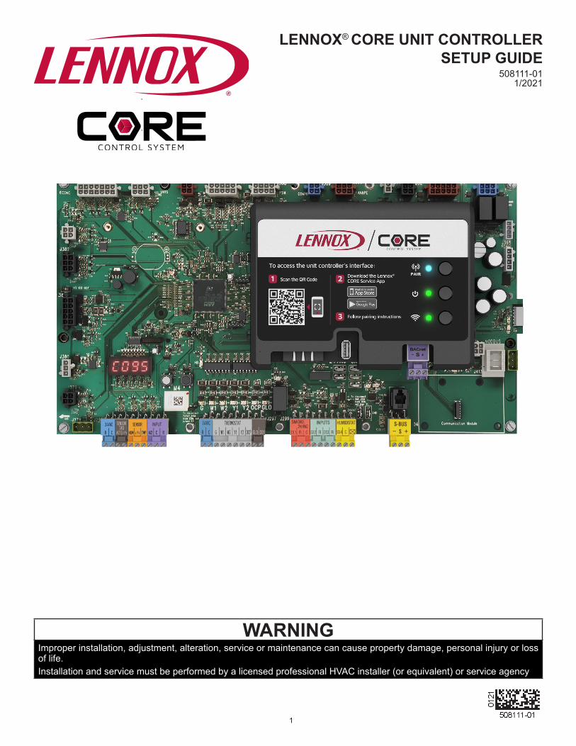
1. CORE Unit Controller OverviewFor all available CORE Control System documentation, go to the Lennox Commercial website.
www.lennoxcommercial.comThe Lennox Core Unit Controller is a multi-processor-based controller. Standard with all Model L™ rooftop units, integrates key technologies that lower installation costs, drivesystemefficiency,andprotectyour investments.TheCORE Unit Controller is a microprocessor-based controller thatprovidesflexiblecontrolofallunitfunctions.Lennox® CORE Service App Connectivity• Setup menu insures proper installation and simplified
setup of the rooftop unit• Detailed data readout updates sensor values in real time
and allows trending• Unit self-test verifies individual critical component and
system performance• Economizer test function ensures economizer is
operating correctly
1.1. Lennox® CORE Service App - Android or iOS Device Minimum System Requirements
• Android hardware requires 2GB RAM and 2GHz Core processor. Tablets are supported.
• Minimum Android 6.0 (Marshmallow) or higher. Recommend Android 10 and Apple products require IOS version 11 or higher.
1.2. Additional Features• Built-In 7-segment display (four character positions) the
unit status and active alarms for easy troubleshooting• Buttons for test and clearing delays• SmartWire™ System with keyed and removable screw
terminalsensurecorrectfieldwiring• Built-in BACnet IP and MS/TP allow open integration to
building management systems• Two-port Ethernet Switch enables daisy chaining for
BACnetIPandautomaticfirmwareupdates
NOTE: Unit Internet Connection required for firmware update only and not for BACnet IP.
• Profilesetupcopieskeysettingsbetweenunitswiththesameconfigurationtoreducesetuptime
• USB port allows a technician to download and transfer unit information to help verify service was performed
• USB software updates on the CORE™ Unit Controller enhance functionality without the need to change components
1.3. ConfigurableSequencesofOperation
• Single-Zone VAV (Discharge Control) Cooling (With room sensor or 24V DDC)
• Three Cooling Stages (With compatible thermostat or DDC / additional relay)
• Four Heating Stages using a room sensor (up to two with thermostat / DDC Controls)
• Four stages in VAV/Discharge Air Control with thermostat input to W1
• Multi-Zone VAV (Discharge Control) Heating and Cooling• Economizer Control Options (See Economizer / Exhaust
Air / Outdoor Air sections)• Exhaust Fan Control Modes for fresh air damper position• Configurablemorningwarm-upandmorningcool-down• Night Setback Mode• Fresh Air Tempering for improved space temperature
control during ventilation’• Demand Control Ventilation• Low Ambient Controls for operation down to 0°F• Humiditrol®+ Operation (Variable Capacity Hot-Gas
Reheat)• Enhanced Dehumidification (Latent Demand Control
without reheat)
1.4. Component Protection / Unit Safeguards
• Compressor Time-Off Delay• Adjustable Blower On/Off Delay• Return Air Temperature Limit Control• Safety Switch Input allows Controller to respond to a
external safety switch trip• Service Relay Output• Thermostat Bounce Delay• Smoke Alarm Mode has four choices (unit off, positive
pressure, negative pressure, purge)• “Strike Three” Protection• Gas Valve Time Delay Between First and Second Stage• Minimum Compressor Run Time
1.5. Control Methods / Interfaces• DDC and 24V Thermostat• BACnet (MS/TP) and IP• LONTalk (Factory & Field Option)• Lennox S-BUS• Compatibility with Lennox Wireless Zone Sensors• Zone Temperature Sensor input• Dehumidistat & Humidity Sensor inputs• Indoor Air Quality Inputs (2)• One IAQ input is report only.• Built-in Control Parameter Defaults• Permanent Diagnostic Code Storage• Field Adjustable Control Parameters (Over 200 settings)• Dirty Filter Switch Input
4
J386 J387 J388 J389 J390 J391 J392 J393
J395
J394
MODBUSJ413
LONTalkModule
24VAC
Gnd
S-BUS SmartWire™System J304
Humidistat
DigitalInputs
Smoke24VAC
Gnd24VAC
ThermostatService Relays
R + CSpare
AnalogInputs
Room and RH Sensors
Sensor IAQ
TX
J358
Duct SensorJ378
4-Character Seven Segment LED
J379
J380
J381
J382
J383
J385J384
J298 J297 J299
SensorIAQ
A11 HUM TMPSensor Inputs
A12 C R
White PushButton
Black PushButton
Service Relays
P5S-BUS
Factory Test
P2 ExpansionCard Connection (C4)
CORE Unit Controller (A55) Wireless Control (W4)
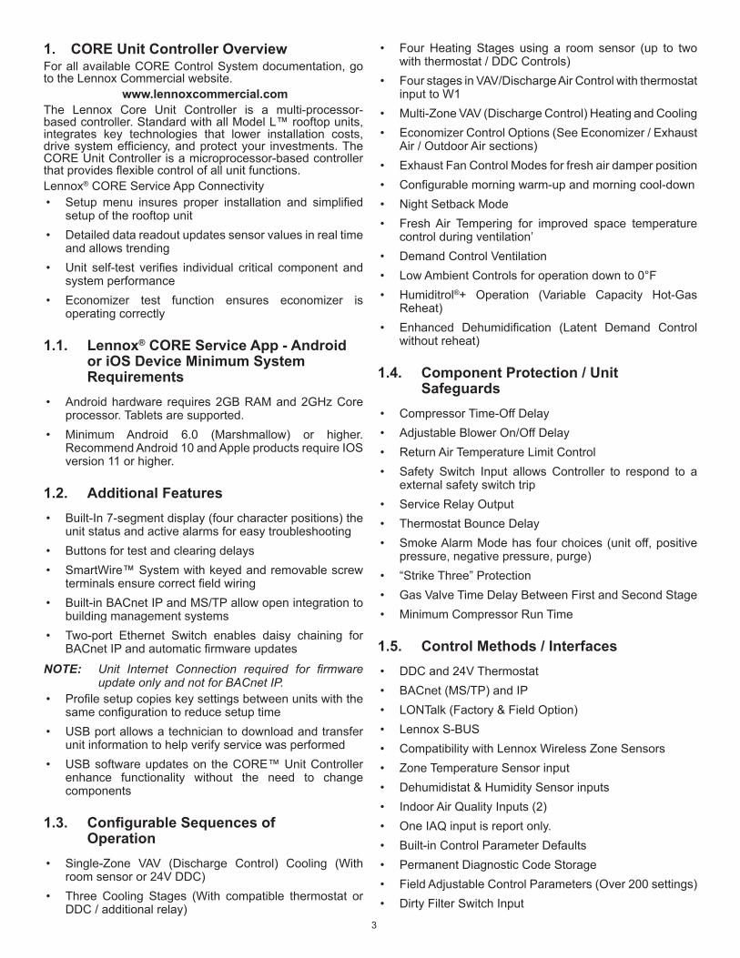
Figure 1. Lennox CORE Unit Controller Interfaces and LEDs Locations
• LED Indicators
NOTE: CORE™ Control System features vary with the type of rooftop unit in which the control is installed.
1.6. Lennox CORE Unit Controller - Connections, Inputs / Outputs, Jumpers, and LEDs Locations
THERMOSTAT COMMON ISOLATION - TSTAT_COM JumperThermostat (TSTAT) sensor commons are located on connector P298 and may be isolated if they are powered remotely. Remove jumper.This jumper is located to the left of P297 connector. This jumper would be removed only in unique situations where the device supplying the thermostat signals to the CORE Unit Controller has its own power source and does not share a common reference voltage with the CORE unit controller. Otherwise the jumper would remain installed across both pins, as shipped from the factory.A. HUMIDISTAT COMMON ISOLATION -: HMD_COM
JumperThe humidity (HUM) sensor commons are located on connector P298 and may be isolated if they are powered remotely. Remove jumper. This jumper is located to the right of P299 connector. This jumper would be removed only in unique situations where the device supplying the thermostat/humidistat signals to the CORE Unit Controller has its own power source and does not share a common reference voltage with the CORE Unit Controller. Otherwise the jumper
would remain installed across both pins, as shipped from the factory.B. W4 CONTROL - USB FLASH DRIVE INTERFACE
USAGE The W4 Control uses a USB type A interface. This USB port is used for verifying service, downloading reports, transferring unitprofilesandperformingfirmwareupdates.On-site data collection requires useof either aUSBflashdrive or download and shared from the CORE Service App. Data written to the drive includes date, time, serial number, catalog number, basic data, error code buffer, and unit configuration.C. S-BUS (SMARTWIRE™) (J304)This is the L-connection interface. This is a R485 network connection with other devices (NCP, comfort sensors, other RTU, etc.).D. MODBUS CONNECTION (J413)This is a TIA-485 serial line over MODBUS (messaging structure) communication. This connection is used for multiple components.E. CORE UNIT CONTROLLER LED INDICATORSNOTE: See “g. Local Interface - four character seven
segment LED - Status Codes” on page 6 for further information.

5
Table 1. LED Operation IndicatorsLED Status Indication Meaning
Heartbeat (HB) (D33)
Green Slow Flash Normal Operation
Green Fast Flash Bootloader/firmwareupdatemode
No light Steady Off No voltage to M3 board or defective board
Green Steady On Unitinconfiguration/testmode(notinnormalmode)
S-BUS / PC Connection (D70 and D71)
BUS (green) Flickering ON Networktrafficpresent
TX (yellow) Flickering ON Unit controller is transmitting
Thermostat Input YellowIndicates a thermostat demand
G - Blower on
W1 - First-Stage Heating
W2 - Second -Stage Heating
Y1 - First-Stage Cooling
Y2 - Second-Stage Cooling
OCP - Occupied
GLO - Global input
MODBUS Two LEDs that indicate transmit (TX) and receive (RX) activity.
Slow Flash = 1 second on; 1 second off.Fast Flash = ½ second on; ½ second off.A“flickering”LEDflashessignificantlyfasterthana“fastflash“.
NOTE: LEDs are energized by 24VAC thermostat inputs.

6
F. LOCAL INTERFACE - PUSH BUTTONS AND HEART BEAT
Figure 2. Push Buttons and Heart Beat
G. LOCAL INTERFACE - FOUR CHARACTER SEVEN SEGMENT LED - STATUS CODES
Table 2. Status CodesStatus Code Definition
PnSt Pre-Install
A173 Smoke
Lout Controller Lockout
Eror Off On Alarm
d300 Delay up to 5 minutes
d020 Delay up to 20 seconds
dhUm Dehumidification
ShEd Compressor Load Shedding
Prht Morning Warmup
Strt Start up
FAH Fresh Air Heating
H050 Heating (50%)
PrCL Pre-Cool
CEoP Cool + Max Open Economizer
CE10 Cool + Modulate Economizer (10%)
FrCL Free Cooling
FAC Fresh Air Cooling
CO78 Cooling (78%)
6715 Blower On - OAS (71%)
623 Blower On (23%)
ioAS No Demand - OAS
idLE No Demand
7
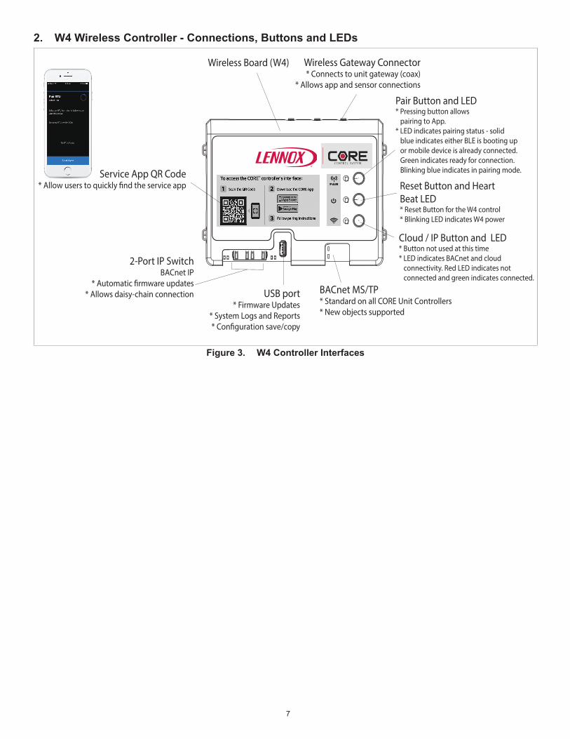
2. W4 Wireless Controller - Connections, Buttons and LEDs
Wireless Board (W4)
Service App QR Code* Allow users to quickly �nd the service app
2-Port IP SwitchBACnet IP
* Automatic �rmware updates* Allows daisy-chain connection USB port
* Firmware Updates* System Logs and Reports* Con�guration save/copy
Wireless Gateway Connector* Connects to unit gateway (coax)
* Allows app and sensor connections
BACnet MS/TP* Standard on all CORE Unit Controllers* New objects supported
Pair Button and LED* Pressing button allows pairing to App.* LED indicates pairing status - solid blue indicates either BLE is booting up or mobile device is already connected. Green indicates ready for connection. Blinking blue indicates in pairing mode.
Reset Button and Heart Beat LED* Reset Button for the W4 control* Blinking LED indicates W4 power
Cloud / IP Button and LED* Button not used at this time* LED indicates BACnet and cloud connectivity. Red LED indicates not connected and green indicates connected.
Figure 3. W4 Controller Interfaces
8
2.1. Wireless Gateway • Return mount antenna that enables wireless connections.• Plenum-rated BLE antenna• Boosts signal from CORE Unit Controller to CORE
Service App
> Wireless room sensors.
> Factory installed placement allows for use in vertical and horizontal applications.
• Return air mount reduces signal loss from roof.• Coax cable connects gateway to W4.
2.2. CORE Service App• Reduces service and install times.• Simple setup and test.• Connects to the CORE Unit Controller via the wireless
gateway.• Pairs with a simple button press (requires physical
access).• Used for install, service, and maintenance of Model L.
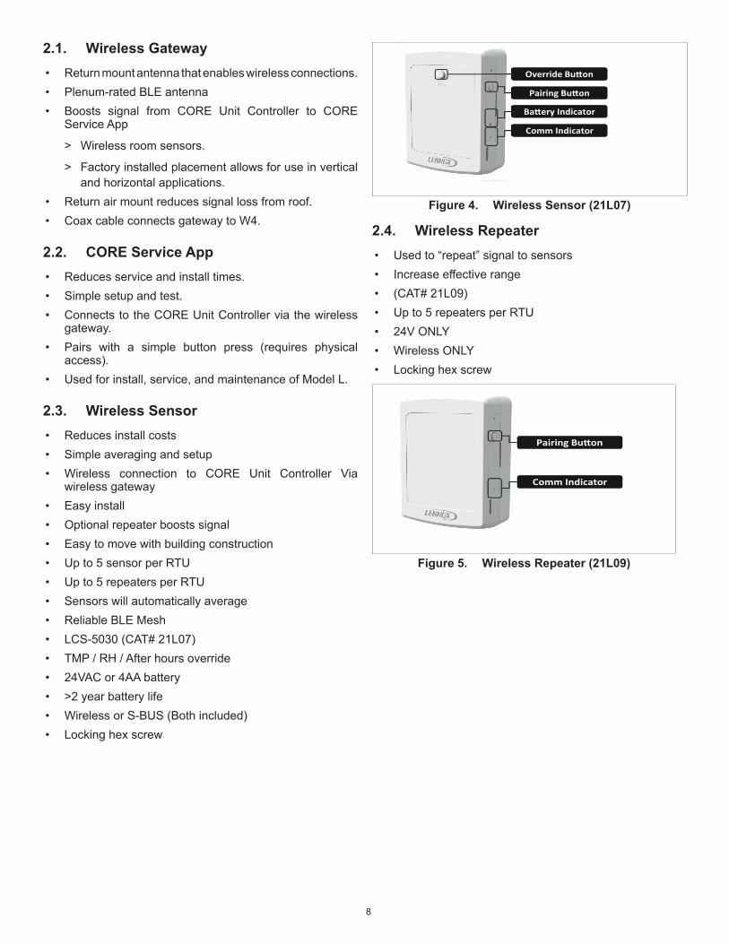
2.3. Wireless Sensor• Reduces install costs• Simple averaging and setup• Wireless connection to CORE Unit Controller Via
wireless gateway• Easy install• Optional repeater boosts signal• Easy to move with building construction• Up to 5 sensor per RTU• Up to 5 repeaters per RTU• Sensors will automatically average• Reliable BLE Mesh• LCS-5030 (CAT# 21L07)• TMP / RH / After hours override• 24VAC or 4AA battery• >2 year battery life• Wireless or S-BUS (Both included)• Locking hex screw
Override Bu�on
Pairing Bu�on
Ba�ery Indicator
Comm Indicator
Override Bu�on
Pairing Bu�on
Ba�ery Indicator
Comm Indicator
Figure 4. Wireless Sensor (21L07)
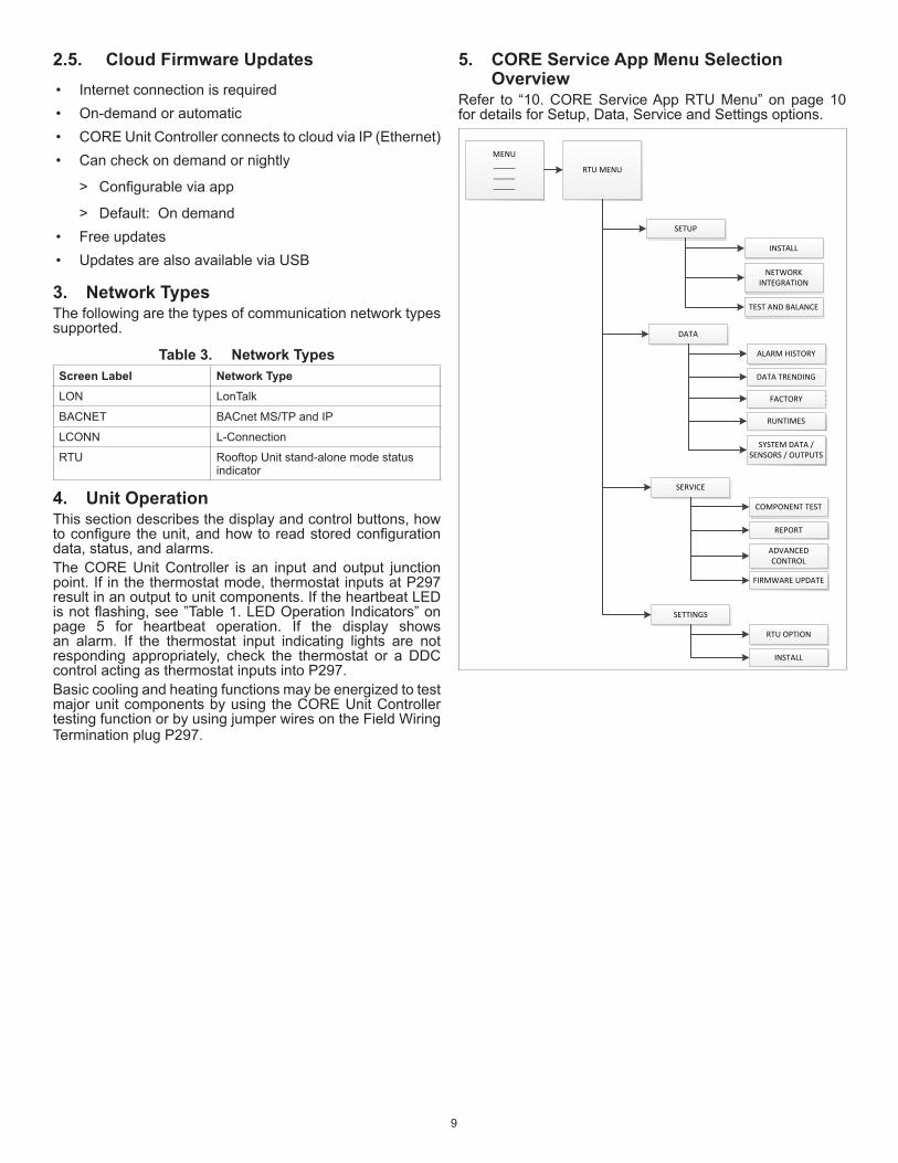
2.4. Wireless Repeater• Used to “repeat” signal to sensors• Increase effective range• (CAT# 21L09)• Up to 5 repeaters per RTU• 24V ONLY• Wireless ONLY• Locking hex screw
Pairing Bu�on
Comm Indicator
Figure 5. Wireless Repeater (21L09)
9
2.5. Cloud Firmware Updates• Internet connection is required• On-demand or automatic• CORE Unit Controller connects to cloud via IP (Ethernet)• Can check on demand or nightly
> Configurableviaapp
> Default: On demand• Free updates• Updates are also available via USB
3. Network TypesThe following are the types of communication network types supported.
Table 3. Network TypesScreen Label Network TypeLON LonTalk
BACNET BACnet MS/TP and IP
LCONN L-Connection
RTU Rooftop Unit stand-alone mode status indicator
4. Unit OperationThis section describes the display and control buttons, how toconfiguretheunit,andhowtoreadstoredconfigurationdata, status, and alarms.The CORE Unit Controller is an input and output junction point. If in the thermostat mode, thermostat inputs at P297 result in an output to unit components. If the heartbeat LED isnotflashing,see”Table1.LEDOperationIndicators”onpage 5 for heartbeat operation. If the display shows an alarm. If the thermostat input indicating lights are not responding appropriately, check the thermostat or a DDC control acting as thermostat inputs into P297.Basic cooling and heating functions may be energized to test major unit components by using the CORE Unit Controller testing function or by using jumper wires on the Field Wiring Termination plug P297.
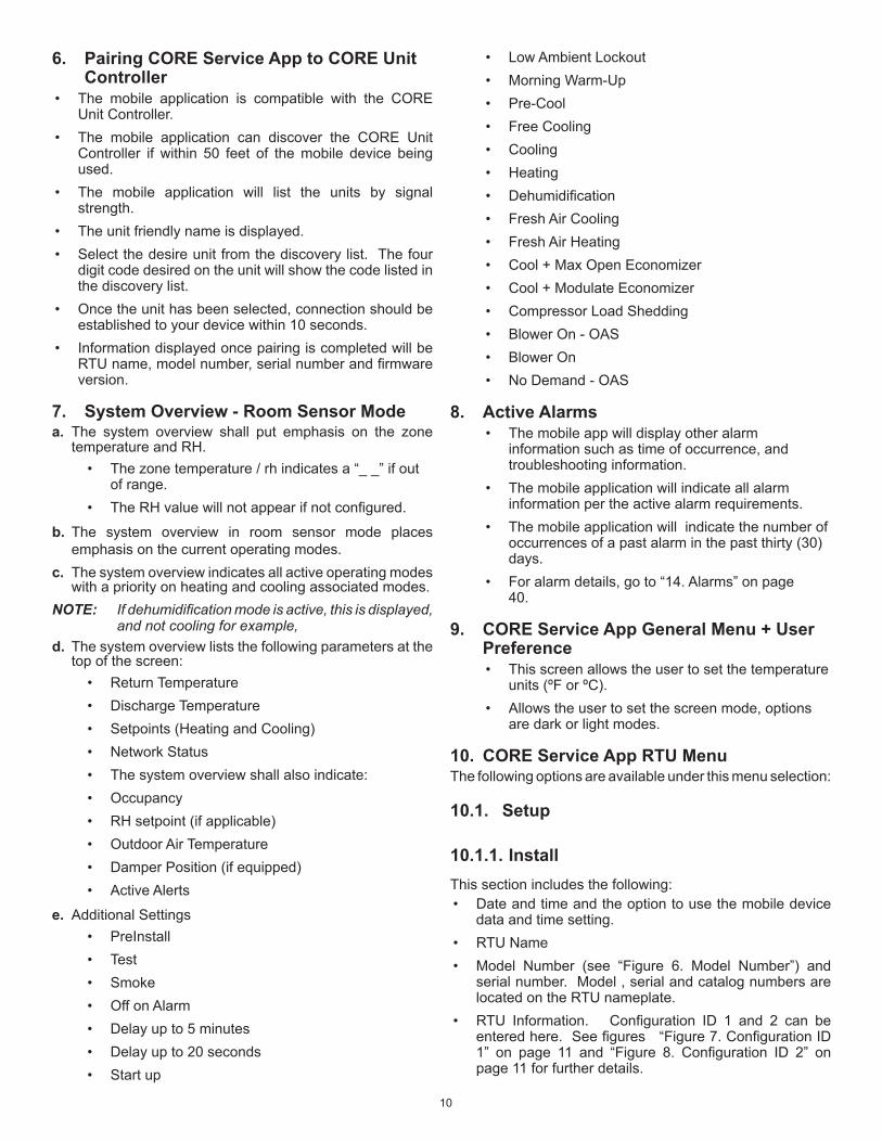
5. CORE Service App Menu Selection Overview
Refer to “10. CORE Service App RTU Menu” on page 10 for details for Setup, Data, Service and Settings options.
MENU_______________
RTU MENU
SETUP
INSTALL
NETWORK INTEGRATION
TEST AND BALANCE
DATA
ALARM HISTORY
DATA TRENDING
FACTORY
RUNTIMES
SYSTEM DATA / SENSORS / OUTPUTS
SERVICE
COMPONENT TEST
REPORT
ADVANCED CONTROL
FIRMWARE UPDATE
SETTINGS
RTU OPTION
INSTALL
10
6. Pairing CORE Service App to CORE Unit Controller
• The mobile application is compatible with the CORE Unit Controller.
• The mobile application can discover the CORE Unit Controller if within 50 feet of the mobile device being used.
• The mobile application will list the units by signal strength.
• The unit friendly name is displayed.• Select the desire unit from the discovery list. The four
digit code desired on the unit will show the code listed in the discovery list.
• Once the unit has been selected, connection should be established to your device within 10 seconds.
• Information displayed once pairing is completed will be RTUname,modelnumber,serialnumberandfirmwareversion.
7. System Overview - Room Sensor Modea. The system overview shall put emphasis on the zone
temperature and RH.• The zone temperature / rh indicates a “_ _” if out
of range.• TheRHvaluewillnotappearifnotconfigured.
b. The system overview in room sensor mode places emphasis on the current operating modes.
c. The system overview indicates all active operating modes with a priority on heating and cooling associated modes.
NOTE: If dehumidification mode is active, this is displayed, and not cooling for example,
d. The system overview lists the following parameters at the top of the screen:
• Return Temperature• Discharge Temperature• Setpoints (Heating and Cooling)• Network Status• The system overview shall also indicate:• Occupancy• RH setpoint (if applicable)• Outdoor Air Temperature• Damper Position (if equipped)• Active Alerts
e. Additional Settings• PreInstall• Test• Smoke• Off on Alarm• Delay up to 5 minutes• Delay up to 20 seconds• Start up
• Low Ambient Lockout• Morning Warm-Up• Pre-Cool• Free Cooling• Cooling• Heating• Dehumidification• Fresh Air Cooling• Fresh Air Heating• Cool + Max Open Economizer• Cool + Modulate Economizer• Compressor Load Shedding• Blower On - OAS• Blower On• No Demand - OAS
8. Active Alarms• The mobile app will display other alarm
information such as time of occurrence, and troubleshooting information.
• The mobile application will indicate all alarm information per the active alarm requirements.
• The mobile application will indicate the number of occurrences of a past alarm in the past thirty (30) days.
• For alarm details, go to “14. Alarms” on page 40.
9. CORE Service App General Menu + User Preference• This screen allows the user to set the temperature
units (ºF or ºC).• Allows the user to set the screen mode, options
are dark or light modes.
10. CORE Service App RTU MenuThe following options are available under this menu selection:
10.1. Setup
10.1.1. InstallThis section includes the following:• Date and time and the option to use the mobile device
data and time setting.• RTU Name• Model Number (see “Figure 6. Model Number”) and
serial number. Model , serial and catalog numbers are located on the RTU nameplate.
• RTU Information. Configuration ID 1 and 2 can beenteredhere.Seefigures“Figure7.ConfigurationID1” on page 11 and “Figure 8. Configuration ID 2” onpage 11 for further details.
11
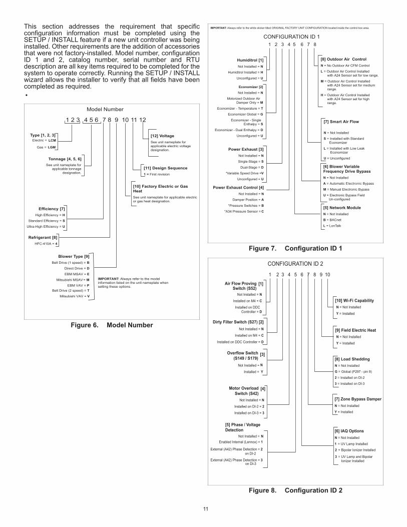
This section addresses the requirement that specificconfiguration information must be completed using theSETUP / INSTALL feature if a new unit controller was being installed. Other requirements are the addition of accessories thatwerenotfactory-installed.Modelnumber,configurationID 1 and 2, catalog number, serial number and RTU description are all key items required to be completed for the system to operate correctly. Running the SETUP / INSTALL wizardallowstheinstallertoverifythatallfieldshavebeencompleted as required.•
Model Number
Type [1, 2, 3]Electric = LCM
Gas = LGM
Tonnage [4, 5, 6]
Efficiency [7]High Efficiency = H
Standard Efficiency = SUltra-High Efficiency = U
[10] Factory Electric or GasHeatSee unit nameplate for applicable electricor gas heat designation.
[11] Design Sequence1 = First revision
[12] VoltageSee unit nameplate forapplicable electric voltagedesignation.
Refrigerant [8]HFC-410A = 4
Blower Type [9]Belt Drive (1 speed) = B
Direct Drive = D EBM MSAV = EMitsubishi MSAV = M
Belt Drive (2 speed) = T
IMPORTANT: Always refer to the modelinformation listed on the unit nameplate whensetting these options.
See unit nameplate forapplicable tonnage
designation.
7 8 9 10 11 121 2 3 4 5 6
EBM VAV = P
Mitsubishi VAV = V
Figure 6. Model Number
CONFIGURATION ID 1
Humiditrol [1]Not Installed = N
Humiditrol Installed = HUnconfigured = U
Economizer [2]Not Installed = N
Motorized Outdoor Air Damper Only = M
Economizer - Temperature = TEconomizer Global = G
Economizer - Single Enthalpy = S
Economizer - Dual Enthalpy = DUnconfigured = U
Power Exhaust [3]Not Installed = NSingle-Stage = S
Dual-Stage = D*Variable Speed Drive = V
Unconfigured = U
Power Exhaust Control [4]Not Installed = N
Damper Position = A *Pressure Switches = B
*A34 Pressure Sensor = C[5] Network ModuleN = Not Installed
B = BACnet
L = LonTalk
[6] Blower VariableFrequency Drive BypassN = Not Installed
A = Automatic Electronic Bypass
M = Manual Electronic Bypass
U = Electronic Bypass Field Un-configured
[7] Smart Air Flow
N = Not Installed
S = Installed with Standard Economizer
L = Installed with Low Leak Economizer
U = Unconfigured
[8] Outdoor Air ControlN = No Outdoor Air CFM Control
L = Outdoor Air Control Installed with A24 Sensor set for low range.
M = Outdoor Air Control Installed with A24 Sensor set for medium range.
H = Outdoor Air Control Installed with A24 Sensor set for high range.
IMPORTANT: Always refer to the white sticker titled ORIGINAL FACTORY UNIT CONFIGURATION located inside the control box area.
1 2 3 4 5 6 7 8
Figure 7. ConfigurationID1
CONFIGURATION ID 2
Not Installed = NInstalled on M4 = CInstalled on DDC
Controller = D
Dirty Filter Switch (S27) [2]Not Installed = N
Installed on M4 = CInstalled on DDC Controller = D
Not Installed = N
Installed = Y
[5] Phase / VoltageDetection
N Not Installed =
Enabled Internal (Lennox) = 1
External (A42) Phase Detection = 2 on DI-2
External (A42) Phase Detection = 3 on DI-3
N = Not Installed
Y = Installed
[8] Load SheddingN = Not Installed
G = Global (P297 - pin 9)
2 = Installed on DI-2
3 = Installed on DI-3
[9] Field Electric Heat
[1]Air Flow ProvingSwitch (S52)
[3]Overflow Switch(S149 / S179)
[4]Motor OverloadSwitch (S42)
Not Installed = NInstalled on DI-2 = 2Installed on DI-3 = 3
[7] Zone Bypass DamperN = Not Installed
Y = Installed
[6] IAQ OptionsN = Not Installed
1 = UV Lamp Installed
1 2 3 4 5 6 7 8 9 10
2 = Bipolar Ionizer Installed
3 = UV Lamp and BipolarIonizer Installed
N = Not Installed
Y = Installed
[10] Wi-Fi Capability
Figure 8. ConfigurationID2

12
10.1.2. Install Menu Navigation
INSTALL
DATETIMEUSE MOBILE DEVICE DATE AND TIME
RTU INFORMATION CONFIGURATION ID1CONFIGURATOIN ID2
DEHUMIDIFICATION MODE DISABLED INSTALL SUMMARY
BLOWER OCCUPIED PREVIOUS COOLING
SELECT SENSOR TYPE NONE
DEHUMIDIFACTION SETPOINTDEHUMIDIFICATION DEADBAND
ENHANCED DEHUMIDIFCATION
NETWORK SENSOR
REHEAT DIGITAL INPUT 4
ON/OFF
ONDEHUMIDIFICATION SETPOINTDEHUMIDIFICATION DEADBANDOVERCOOL LIMIT
ON/OFF
ON
OFF
LOCAL SENSOR ENHANCED DEHUMIDIFCATION
REPORT RELATIVE HUMIDITY ONLY
SELECT SENSOR TYPE
NETWORK SENSOR
LOCAL SENSOR
ON/OFF INSTALL SUMMARY OFFENHANCED DEHUMIDIFCATION
DEHUMIDIFACTION SETPOINTDEHUMIDIFICATION DEADBAND OVERCOOL LIMIT
ONPREVIOUS COOLING
BLOWER OCCUPIED
SELECT SENSOR TYPE
SELECT SENSOR TYPE
NONE
REHEAT DIGITAL INPUT 4
NETWORK SENSOR
LOCAL SENSOR
INSTALL SUMMARY
DEHUMIDIFACTION SETPOINTDEHUMIDIFICATION DEADBAND OVERCOOL LIMIT
DEHUMIDIFACTION SETPOINTDEHUMIDIFICATION DEADBAND
ENHANCED DEHUMIDIFCATION ON/OFF
DEHUMIDIFICATION DEADBAND OVERCOOL LIMIT
YES
NO CONDITIONS
ON/OFF YES
DEHUMIDIFICATION DEADBAND OVERCOOL LIMIT
NO
NO
NONE
REHEAT DIGITAL INPUT 4
NETWORK SENSOR
LOCAL SENSOR
INSTALL SUMMARY
DEHUMIDIFACTION SETPOINTDEHUMIDIFICATION DEADBAND OVERCOOL LIMIT
DEHUMIDIFACTION SETPOINTDEHUMIDIFICATION DEADBAND
ENHANCED DEHUMIDIFCATION ON/OFF
DEHUMIDIFICATION DEADBAND OVERCOOL LIMIT
YES
ON/OFF YES
NO
SELECT SENSOR TYPE
OFF
DEHUMIDIFICATION DEADBAND OVERCOOL LIMIT
Figure 9. Install Menu Structure
13
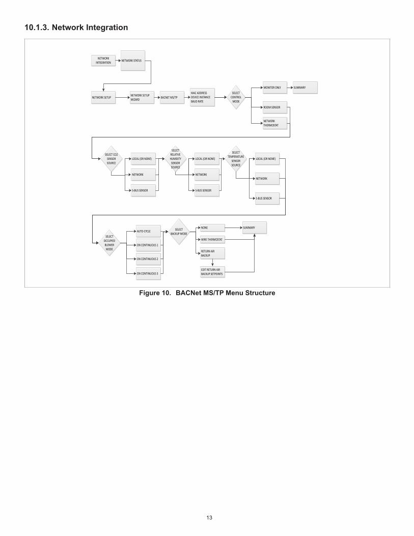
10.1.3. Network Integration
NETWORK INTEGRATION NETWORK STATUS
NETWORK SETUP NETWORK SETUP WIZARD BACNET MS/TP
MAC ADDRESSDEVICE INSTANCEBAUD RATE
MONITOR ONLY SUMMARY
ROOM SENSOR
LOCAL (OR NONE)
AUTO-CYCLE
ON CONTINUOUS 1
ON CONTINUOUS 2
ON CONTINUOUS 3
NONE
WIRE THERMOSTAT
RETURN AIR BACKUP
EDIT RETURN AIR BACKUP SETPOINTS
NETWORK
S-BUS SENSOR
LOCAL (OR NONE)
NETWORK
S-BUS SENSOR
LOCAL (OR NONE)
NETWORK
S-BUS SENSOR
SUMMARY
NETWORK THERMOSTAT
SELECT CONTROL
MODE
SELECT RELATIVE HUMIDITY
SENSOR SOURCE
SELECT TEMPERATURE
SENSOR SOURCE
SELECT CO2 SENSOR SOURCE
SELECT OCCUPIED BLOWER
MODE
SELECT BACKUP MODE
Figure 10. BACNet MS/TP Menu Structure
14
NETWORK INTEGRATION NETWORK STATUS
NETWORK SETUP NETWORK SETUP WIZARD BACNET IP NETWORK AND CLOUD/IP
CONFIGURATION
NETWORKSTATICDYNAMIC (DHCP)NONE
CLOUD/IP CONFIGURATIONIP ADDRESSSUBNET MASKDNSDEFAULT GATEWAYPORTMAC ADDRESS
ENTER BACNET OVER IP DEVICE INSTANCE
MONITOR ONLY SUMMARY
ROOM SENSOR
NETWORK THERMOSTAT
SELECT CONTROL
MODE LOCAL (OR NONE)
AUTO-CYCLE
ON CONTINUOUS 1
ON CONTINUOUS 2
ON CONTINUOUS 3
NONE
WIRE THERMOSTAT
RETURN AIR BACKUP
EDIT RETURN AIR BACKUP SETPOINTS
NETWORK
S-BUS SENSOR
LOCAL (OR NONE)
NETWORK
S-BUS SENSOR
LOCAL (OR NONE)
NETWORK
S-BUS SENSOR
SUMMARY
SELECT RELATIVE HUMIDITY
SENSOR SOURCE
SELECT TEMPERATURE
SENSOR SOURCE
SELECT CO2 SENSOR SOURCE
SELECT OCCUPIED BLOWER
MODE
SELECT BACKUP MODE
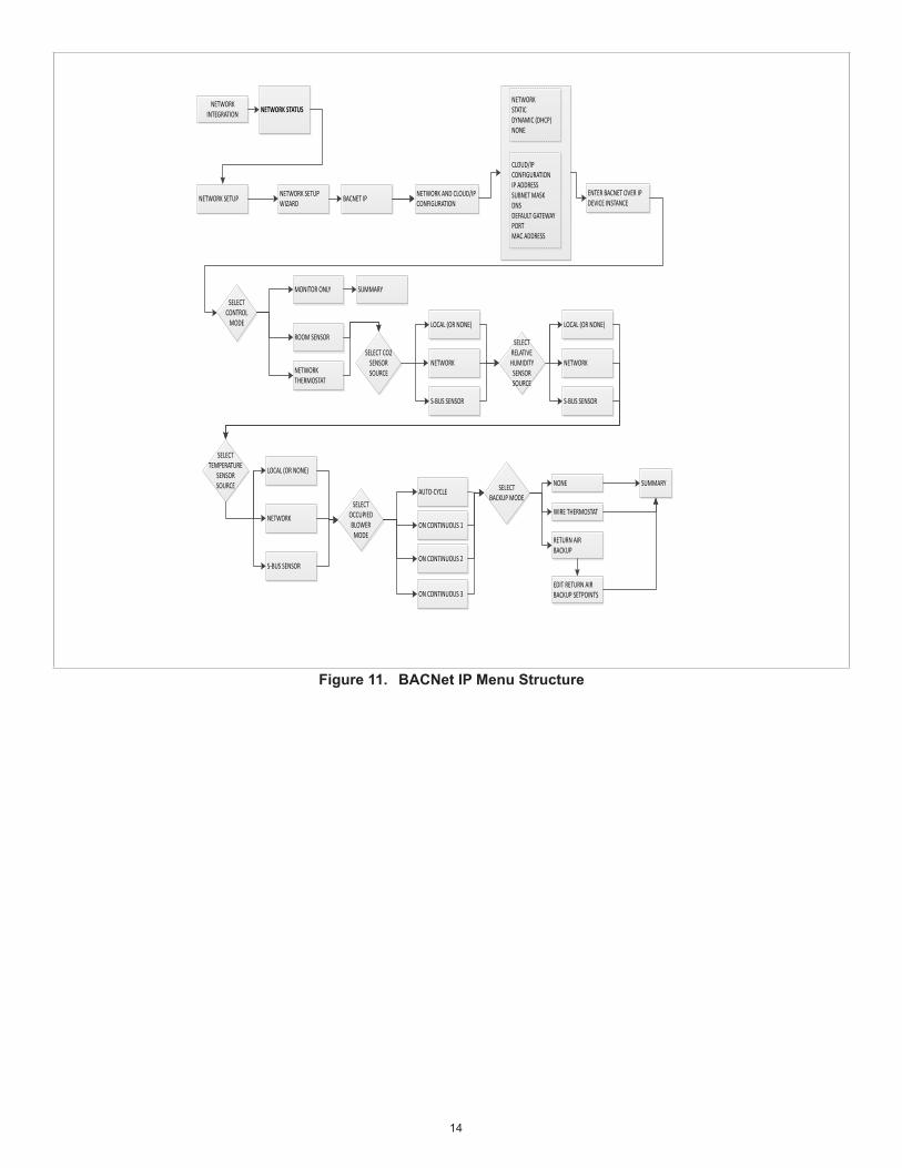
Figure 11. BACNet IP Menu Structure

15
NETWORK INTEGRATION NETWORK STATUS
NETWORK SETUP NETWORK SETUP WIZARD LONTALK
MONITOR ONLY SUMMARY
ROOM SENSOR
LOCAL (OR NONE)
AUTO-CYCLE
ON CONTINUOUS 1
ON CONTINUOUS 2
ON CONTINUOUS 3
NONE
WIRE THERMOSTAT
RETURN AIR BACKUP
EDIT RETURN AIR BACKUP SETPOINTS
NETWORK
LOCAL (OR NONE)
NETWORK
LOCAL (OR NONE)
NETWORK
SUMMARY
SELECT CONTROL
MODE
SELECT RELATIVE HUMIDITY SENSOR
SOURCE
SELECT TEMPERATURE
SENSOR SOURCE
SELECT CO2 SENSOR SOURCE
SELECT OCCUPIED BLOWER
MODE
SELECT BACKUP MODE
Figure 12. LonTalk Menu Structure
16
NETWORK INTEGRATION NETWORK STATUS
NETWORK SETUP NETWORK SETUP WIZARD S-BUS S-BUS ADDRESS
MONITOR ONLY SUMMARY
ROOM SENSOR
LOCAL (OR NONE)
AUTO-CYCLE
ON CONTINUOUS 1
ON CONTINUOUS 2
ON CONTINUOUS 3
NONE
WIRE THERMOSTAT
RETURN AIR BACKUP
EDIT RETURN AIR BACKUP SETPOINTS
NETWORK
S-BUS SENSOR
LOCAL (OR NONE)
NETWORK
S-BUS SENSOR
LOCAL (OR NONE)
NETWORK
S-BUS SENSOR
SUMMARY
NETWORK THERMOSTAT
SELECT CONTROL
MODE
SELECT RELATIVE HUMIDITY
SENSOR SOURCE
SELECT TEMPERATURE
SENSOR SOURCE
SELECT CO2 SENSOR SOURCE
SELECT OCCUPIED BLOWER
MODE
SELECT BACKUP MODE
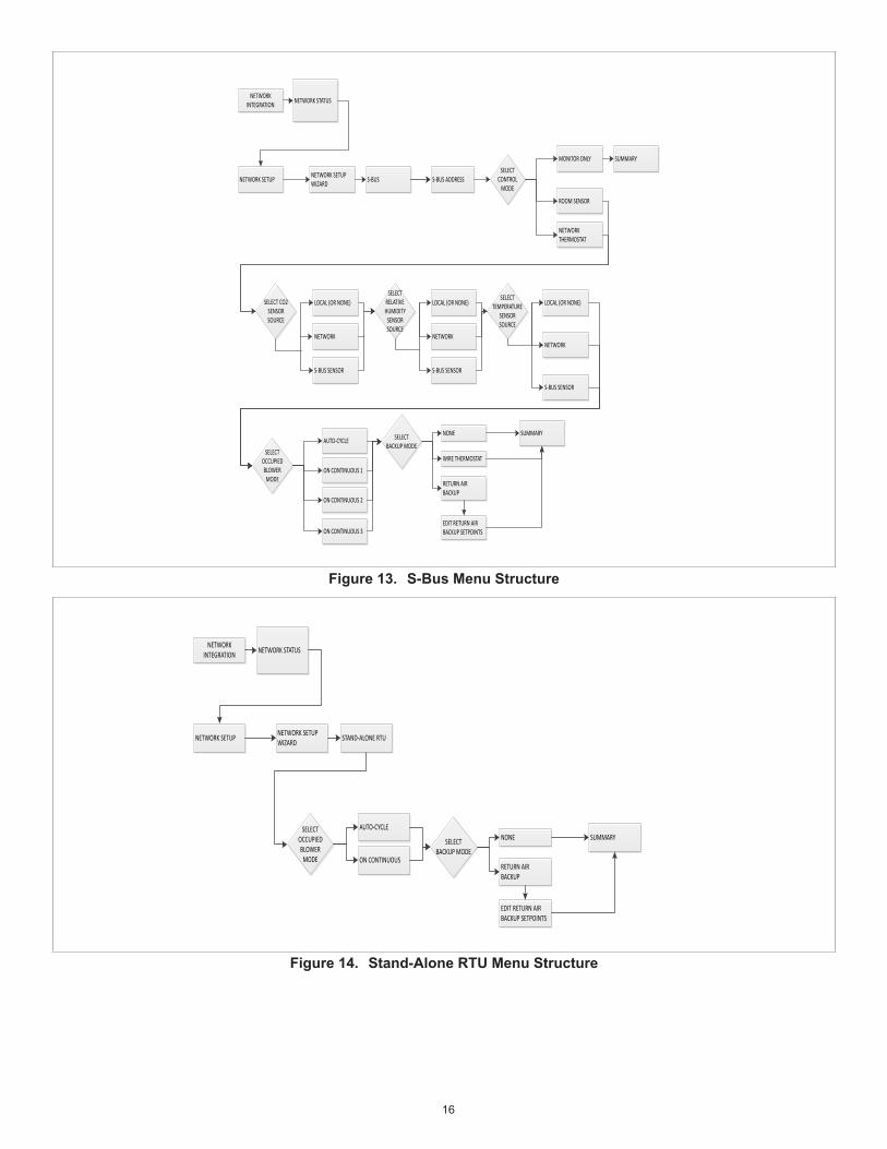
Figure 13. S-Bus Menu Structure
NETWORK INTEGRATION NETWORK STATUS
NETWORK SETUP NETWORK SETUP WIZARD STAND-ALONE RTU
AUTO-CYCLE
ON CONTINUOUS
NONE
RETURN AIR BACKUP
EDIT RETURN AIR BACKUP SETPOINTS
SUMMARYSELECT
OCCUPIED BLOWER
MODE
SELECT BACKUP MODE
Figure 14. Stand-Alone RTU Menu Structure

17
NETWORK INTEGRATION NETWORK STATUS
NETWORK SETUP WIRELESS SENSOR NETWORK SETUP PROVISION MODIFY THE RTU
NAME (OPTIONAL) PROVISION RTU RTU PROVISION
ADD NODE
NETWORK NODES
OPERATIONS – FACTORY RESET SENSOR NETWORK
INFORMATION - MODEL NUMBER- SERIAL NUMBER- FIRMWARE VERSION
OPERATIONS- RENAME RTU - DEPROVISION RTU
SENSOR NETWORK - GROUP NUMBER- NODE NUMBER- FUNCTIONS (PROXY, RELAY, FRIEND)
PROVISON SENSOR NETWORK (CUSTOM NAME FOR NODE (OPTIONAL)
PRESS BEACONING BUTTON NODE PROVISION
Figure 15. Wireless Sensor Network Setup Menu Structure
NETWORK INTEGRATION
NETWORK SETUP CLOUD/IP CONFIGURATION
NETWORK STATUS
REMOTE SERVER ACCESSNETWORKSTATICDYNAMIC (DHCP)NONE
CLOUD/IP CONFIGURATIONIP ADDRESSSUBNET MASKDNSDEFAULT GATEWAYPORTMAC ADDRESS
STATIC IP CLOUD IP CONFIGURATION
REMOTE SERVER ACCESS
Figure 16. Cloud/IPConfigurationMenuStructure

18
10.1.4. Test and Balance• Blower: Includes Blower Calibration, MSAV Blower and VAV Calibration,• Damper: Includes Economizer Options, Free Cooling, Damper Calibration (closed and open),
TEST AND BALANCE
BLOWER
DAMPER
TEST AND BALANCE
MSAV BLOWERCFM SETTINGS
START AND STOP BLOWER SUMMARY
DAMPER CALIBRATION CLOSE DAMPER
VAV BLOWEROPEN ALL ZONE BOXES
VAV BLOWERSTART
VAV CALIBRATOINBLOWER ONSTATIC PRESSURE
VAV CALIBRATOINSTATIC PRESSURE SETPONT
DAMPER CALIBRATION OPEN DAMPER
DAMPER CALIBRATION TURN ON BLOWER
BLOWER SPEED HIGH -MINIMUM DAMPER POSITION
BLOWER SPEED LOW - MINIMUM DAMPER POSITION
SELECT VENTILATION
OPTION BUILDING PRESSURE CONTROL
DEMAND CONTROL VENTILATION
NONE
SET POWER EXHAUST
MODE
BLOWER ON
EXTERNAL ENABLE
OCCUPIED
ALWAYS
SET ECONOMIZER TRAVEL SETPOINT
SET BUILDING PRESSURE SETPOINT
SET FRESH AIR SETPOINTS
SUMMARY
SET BUILDING PRESSURE SETPOINT
Figure 17. Motorized Outdoor Air Damper Only Menu Structure
TEST AND BALANCE
BLOWER
DAMPER
TEST AND BALANCE
MSAV BLOWERCFM SETTINGS
START AND STOP BLOWER SUMMARY
DAMPER CALIBRATION CLOSE DAMPER
VAV BLOWEROPEN ALL ZONE BOXES
VAV BLOWERSTART
VAV CALIBRATOINBLOWER ONSTATIC PRESSURE
VAV CALIBRATOINSTATIC PRESSURE SETPONT
DAMPER CALIBRATION OPEN DAMPER
DAMPER CALIBRATION TURN ON BLOWER
BLOWER SPEED HIGH -MINIMUM DAMPER POSITION
BLOWER SPEED LOW - MINIMUM DAMPER POSITION
SELECT VENTILATION
OPTION BUILDING PRESSURE CONTROL
DEMAND CONTROL VENTILATION
NONE
SET POWER EXHAUST
MODE
BLOWER ON
EXTERNAL ENABLE
OCCUPIED
ALWAYS
SET ECONOMIZER TRAVEL SETPOINT
SET BUILDING PRESSURE SETPOINT
SET FRESH AIR SETPOINTS
SUMMARY
SET BUILDING PRESSURE SETPOINT
SELECT ECONOMIZER
OPTION
TEMPERATURE OFFSET
TEMPERATURE SETPOINT
SET TEMPERATURE OFFSET
SET FREE COOLING SUPPLY SETPOINT
Figure 18. Economizer - Temperature Menu Structure

19
TEST AND BALANCE
BLOWER
DAMPER
TEST AND BALANCE
MSAV BLOWERCFM SETTINGS
START AND STOP BLOWER SUMMARY
DAMPER CALIBRATION CLOSE DAMPER
VAV BLOWEROPEN ALL ZONE BOXES
VAV BLOWERSTART
VAV CALIBRATOINBLOWER ONSTATIC PRESSURE
VAV CALIBRATOINSTATIC PRESSURE SETPONT
DAMPER CALIBRATION OPEN DAMPER
DAMPER CALIBRATION TURN ON BLOWER
BLOWER SPEED HIGH -MINIMUM DAMPER POSITION
BLOWER SPEED LOW - MINIMUM DAMPER POSITION
SELECT VENTILATION
OPTION BUILDING PRESSURE CONTROL
DEMAND CONTROL VENTILATION
NONE
SET POWER EXHAUST
MODE
BLOWER ON
EXTERNAL ENABLE
OCCUPIED
ALWAYS
SET ECONOMIZER TRAVEL SETPOINT
SET BUILDING PRESSURE SETPOINT
SET FRESH AIR SETPOINTS
SUMMARY
SET BUILDING PRESSURE SETPOINT
SELECT ECONOMIZER
OPTION
SET FREE COOLING SUPPLY SETPOINT
Figure 19. Economizer - Global Menu Structure
TEST AND BALANCE
BLOWER
DAMPER
TEST AND BALANCE
MSAV BLOWERCFM SETTINGS
START AND STOP BLOWER SUMMARY
SELECT ECONOMIZER OPTIONENTHALPY OFFSET
FREE COOLING SET FREE COOLING SUPPLY AIR SETPONT
DAMPER CALIBRATION CLOSE DAMPER
VAV BLOWEROPEN ALL ZONE BOXES
VAV BLOWERSTART
VAV CALIBRATOINBLOWER ONSTATIC PRESSURE
VAV CALIBRATOINSTATIC PRESSURE SETPONT
DAMPER CALIBRATION OPEN DAMPER
DAMPER CALIBRATION TURN ON BLOWER
BLOWER SPEED HIGH -MINIMUM DAMPER POSITION
BLOWER SPEED LOW - MINIMUM DAMPER POSITION
SELECT VENTILATION
OPTION BUILDING PRESSURE CONTROL
DEMAND CONTROL VENTILATION
NONE
SET POWER EXHAUST
MODE
BLOWER ON
EXTERNAL ENABLE
OCCUPIED
ALWAYS
SET ECONOMIZER TRAVEL SETPOINT
SET BUILDING PRESSURE SETPOINT
SET FRESH AIR SETPOINTS
SUMMARY
SET BUILDING PRESSURE SETPOINT
Figure 20. Economizer - Single or Dual Enthalpy Menu Structure

20
10.2. Data
10.2.1. Alarm HistoryThe unitary controller will produce active and past alarm codes. As such, the mobile application will show all active alarm codes, and a limited history of formerly-active alarm codes, based upon the storage capacity of the unitary controller. The CORE Service application will:• Display alarm information received from the unitary controller.• Display action alerts. Alarms will be displayed in chronological order from most recent to last recent.• Display other alarm information such as time of occurrence, and troubleshooting information.• Indicate all alarm information per the active alarm requirements.• Indicate the number of occurrences of an alarm in the past thirty (30) days.• See “Table 11. CORE Control System Alarm and Event Codes” on page 40 for alarm details.
ALARM HISTORY VIEW AND CLEAR ALARMS
Figure 21. Alarm Menu Structure
10.2.2. Data Trending‘Trended data within the CORE controller is stored internally for up to two weeks and available in a user friendly format at X interval for help in troubleshooting previous operation with granular historical data.’The main purpose of this feature is for troubleshooting a unit. Having granular, time-sensitive information is critical for this purpose. This is why having at least 5 minute intervals is set.
DATA TRENDING
TEMPERATUREHEATING STAGERELATIVE HUMIDITYIAQ
SHARE DATA
Figure 22. Data Trending Menu Structure
21
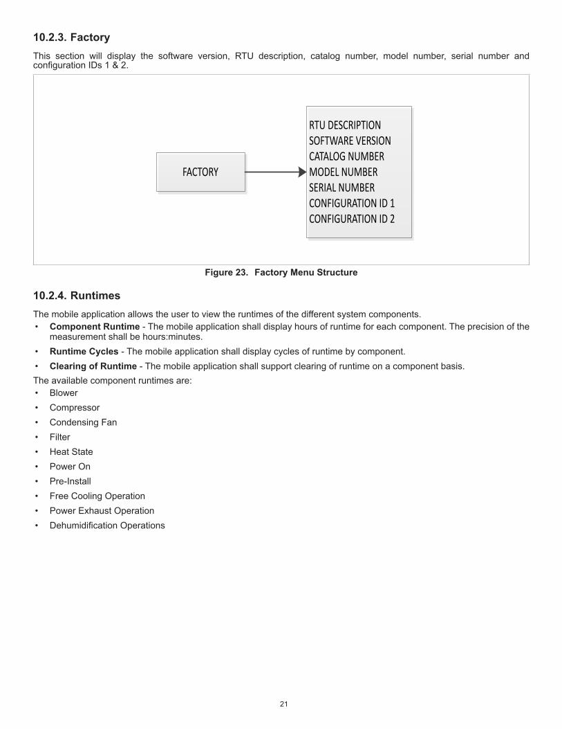
10.2.3. FactoryThis section will display the software version, RTU description, catalog number, model number, serial number and configurationIDs1&2.
FACTORY
RTU DESCRIPTIONSOFTWARE VERSIONCATALOG NUMBERMODEL NUMBERSERIAL NUMBERCONFIGURATION ID 1CONFIGURATION ID 2
Figure 23. Factory Menu Structure
10.2.4. RuntimesThe mobile application allows the user to view the runtimes of the different system components.• Component Runtime - The mobile application shall display hours of runtime for each component. The precision of the
measurement shall be hours:minutes.• Runtime Cycles - The mobile application shall display cycles of runtime by component. • Clearing of Runtime - The mobile application shall support clearing of runtime on a component basis.The available component runtimes are:• Blower• Compressor• Condensing Fan• Filter • Heat State• Power On• Pre-Install• Free Cooling Operation• Power Exhaust Operation• DehumidificationOperations

22
RUNTIMES
RUNTIME REPORTINGBLOWERBELTCOMPRESSOR 1COMPRESSOR 2COMPRESSOR 3COMPRESSOR 4CONDENSER FAN 1CONDENSER FAN 2CONDENSER FAN 3CONDENSER FAN 4FILTERDEHUMIDIFCATONPOWER ON PRE-INSTALLFREE COOLING OPERATIONPOWER EXHAUST STAGE 1
Figure 24. Runtimes Menu Structure

23
10.2.5. System Data / Sensor Data / OutputThe follow inputs and outputs are as follows:• Local Inputs. Examples are local thermostat inputs, sensors, digital inputs, setpoints and advanced.• Network Inputs. Examples are BACnet MS/TP, BACnet IP, Lontalk and S-Bus• Outputs. Examples are compressor, reheat coil, outdoor fans, heat status, damper, blower, power exhaust and other
service relay output and Crankcase Heater 1 through 4.
SYSEM DATA / SENSORS / OUTPUTS
INPUTS AND OUTPUTS LOCAL THERMOSTAT INPUTS
SENSORS
DIGITAL INPUTS
SETPOINTS
ADVANCED
BACNET MS/TP
BACNET IP
S-BUS
INPUTS
WIRELESS SENSORS
LOCAL INPUTS
NETWORK INPUTS
OUTPUTS
COMPRESSOR
REHEAT COIL
OUTDOOR FANS
HEAT STATUS
DAMPER
BLOWER
POWER EXHAUST
OTHER
CIRCUIT 1CIRCUIT 2CIRCUIT 3CIRCUIT4
LOCAL INPUT SETPOINTS
Figure 25. System Data / Sensors / Outputs Menu Structure

24
10.3. Service
10.3.1. Component TestFor cooling, the following tests can be run:• Cooling Stages 1 through 4 - Tests are discharge and return air temperatures, compressor status and percent demand.• Same tests listed above is available for all compressors present.For heating, the following tests can be run:• Heat Stages 1 through 4 - Tests are discharge and return air temperatures, and percent demand.Other tests:• Blower Speed• Damper Position• Power Exhaust• Outdoor Fans 1 through 4
COMPONENT TEST COOLING STAGE 1
COOLING STAGE 1, 2, 3 OR 4COMPRESSOR 1, 2, 3 OR 4COMPRESSOR 2, 2, 3 OR 4COMPRESSOR 3, 2, 3 OR 4COMPRESSOR 4, 2, 3 OR 4
COOLING
BLOWER
DAMPERDAMMPER POSITION
POWER EXHAUST
COOLING STAGE 2
COOLING STAGE 3
COOLING STAGE 4
BLOWER SPEED AND CFM
DAMPER POSITION AND DAMPER FEEDBACK
STATUS
OUTDOOR FAN
FAN 1
FAN 1, 2, 3 AND 4 STATUSFAN 2
FAN 3
FAN 4
START & STOP TEST
START & STOP TEST
START & STOP TEST
START & STOP TEST
START & STOP TEST
OUTPUTS SERVICE RELAY = ON OR OFF
Figure 26. Component Test Menu Structure

25
10.3.2. ReportThis sectionprovides service reports, system logs, systemprofileanduserprofile. All logsand reportsandeither bedownloaded to the via the W4• Service reports - These reports are saved to the root directory of the USB storage device. In addition you can save the
report to the mobile device being used and either text or email.• System Logs - These logs are saved to the root directory of the USB storage device. In addition you can save the report
to the mobile device being used or either e-mailed or use the device’s share feature. There is also an option for data analytic uploads as well.
• SystemandUserProfile-TheprofileissavedtotherootdirectoryoftheUSBstoragedevice.Inadditionyoucansavethereporttothemobiledevicebeingusedore-mailed.Thereisalsotheoptioninthissectiontoloadasystemprofilefrom USB as well.
REPORT REPORT NAMEFILE NAME
SERVICE REPORT
SYSTEM LOGS
SYSTEM PROFILE
USB STORAGE
USER PROFILE
MOBILESAVESHARE
USBSAVESHARE
REPORT NAMEFILE NAME
MOBILESAVESHARE
USBSAVESHARE
SAVE USER PROFILE
LOAD USER PROFILE
Figure 27. Report Menu Structure
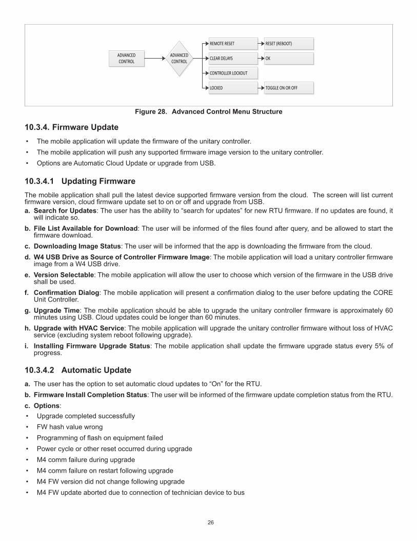
10.3.3. Advanced ControlThe interface will allow for the ability to remote reset the controller.• Theinterfaceshallpresentaconfirmationdialogtotheuserbeforeproceedingwiththeresetcommand• The interface shall indicate to the user that re-pairing will be necessary following the reboot (assuming this is necessary)The component test functionality includes a support a “ClearDelays” functionality.The clear delays functionality will clear timers in the CORE Control System.The interface supports a “clear lockouts”.Features are:• Remote Reset• Clear Delays• Controller Lockout - Locked or unlocked.
26
ADVANCED CONTROL
ADVANCED CONTROL
REMOTE RESET
CLEAR DELAYS
CONTROLLER LOCKOUT
LOCKED
RESET (REBOOT)
OK
TOGGLE ON OR OFF
Figure 28. Advanced Control Menu Structure
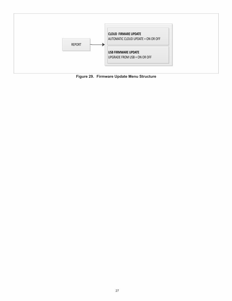
10.3.4. Firmware Update• Themobileapplicationwillupdatethefirmwareoftheunitarycontroller.• Themobileapplicationwillpushanysupportedfirmwareimageversiontotheunitarycontroller.• Options are Automatic Cloud Update or upgrade from USB.
10.3.4.1 Updating FirmwareThemobileapplicationshallpullthelatestdevicesupportedfirmwareversionfromthecloud.Thescreenwilllistcurrentfirmwareversion,cloudfirmwareupdatesettoonoroffandupgradefromUSB.a. Search for Updates: Theuserhastheabilityto“searchforupdates”fornewRTUfirmware.Ifnoupdatesarefound,it
will indicate so.b. File List Available for Download: Theuserwillbeinformedofthefilesfoundafterquery,andbeallowedtostartthe
firmwaredownload.c. Downloading Image Status: Theuserwillbeinformedthattheappisdownloadingthefirmwarefromthecloud.d. W4 USB Drive as Source of Controller Firmware Image: Themobileapplicationwillloadaunitarycontrollerfirmware
image from a W4 USB drive.e. Version Selectable: ThemobileapplicationwillallowtheusertochoosewhichversionofthefirmwareintheUSBdrive
shall be used.f. ConfirmationDialog: ThemobileapplicationwillpresentaconfirmationdialogtotheuserbeforeupdatingtheCORE
Unit Controller.g. Upgrade Time: Themobileapplicationshouldbeabletoupgradetheunitarycontrollerfirmwareisapproximately60
minutes using USB. Cloud updates could be longer than 60 minutes.h. Upgrade with HVAC Service: ThemobileapplicationwillupgradetheunitarycontrollerfirmwarewithoutlossofHVAC
service (excluding system reboot following upgrade).i. Installing Firmware Upgrade Status: Themobileapplicationshallupdatethefirmwareupgradestatusevery5%of
progress.
10.3.4.2 Automatic Updatea. The user has the option to set automatic cloud updates to “On” for the RTU.b. Firmware Install Completion Status: TheuserwillbeinformedofthefirmwareupdatecompletionstatusfromtheRTU.c. Options:• Upgrade completed successfully• FW hash value wrong• Programmingofflashonequipmentfailed• Power cycle or other reset occurred during upgrade• M4 comm failure during upgrade• M4 comm failure on restart following upgrade• M4 FW version did not change following upgrade• M4 FW update aborted due to connection of technician device to bus
27
REPORT
CLOUD FIRMARE UPDATEAUTOMATIC CLOUD UPDATE = ON OR OFF
USB FIRMWARE UPDATEUPGRADE FROM USB = ON OR OFF
Figure 29. Firmware Update Menu Structure
28
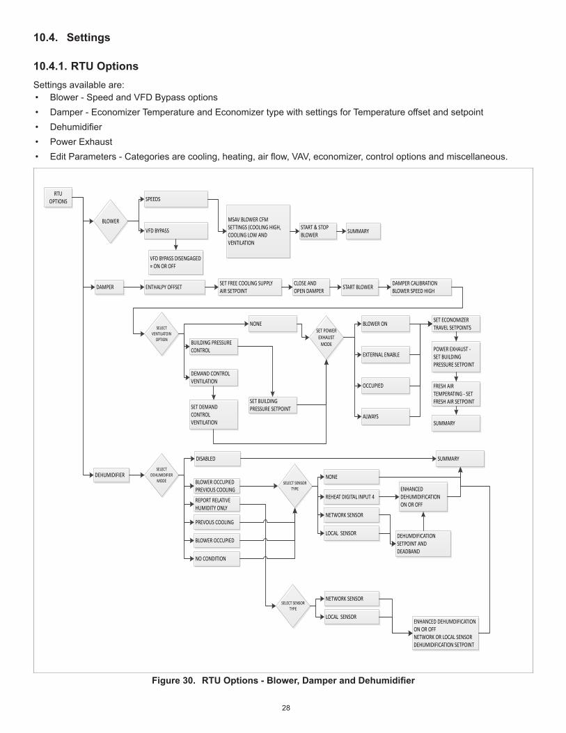
10.4. Settings
10.4.1. RTU OptionsSettings available are:• Blower - Speed and VFD Bypass options• Damper - Economizer Temperature and Economizer type with settings for Temperature offset and setpoint• Dehumidifier• Power Exhaust• EditParameters-Categoriesarecooling,heating,airflow,VAV,economizer,controloptionsandmiscellaneous.
RTU OPTIONS SPEEDS
MSAV BLOWER CFM SETTINGS (COOLING HIGH, COOLING LOW AND VENTILATION
BLOWER
SELECT DEHUMIDIFIER
MODE
VFD BYPASS
ENTHALPY OFFSET
START & STOP BLOWER
SET FREE COOLING SUPPLY AIR SETPOINT
SUMMARY
VFD BYPASS DISENGAGED = ON OR OFF
CLOSE AND OPEN DAMPER START BLOWER DAMPER CALIBRATION
BLOWER SPEED HIGH
SELECT VENTILATOIN
OPTION
NONE
BUILDING PRESSURE CONTROL
DEMAND CONTROL VENTILATION
SET POWER EXHAUST
MODE
BLOWER ON
EXTERNAL ENABLE
OCCUPIED
ALWAYS
SET ECONOMIZER TRAVEL SETPOINTS
POWER EXHAUST - SET BUILDING PRESSURE SETPOINT
FRESH AIR TEMPERATING - SET FRESH AIR SETPOINT
SUMMARY
SET BUILDING PRESSURE SETPOINTSET DEMAND
CONTROL VENTILATION
DAMPER
DEHUMIDIFIER
DISABLED
BLOWER OCCUPIED PREVIOUS COOLING
REPORT RELATIVE HUMIDITY ONLY
PREVOUS COOLING
BLOWER OCCUPIED
NO CONDITION
SUMMARY
NONE
REHEAT DIGITAL INPUT 4
NETWORK SENSOR
LOCAL SENSOR
SELECT SENSOR TYPE ENHANCED
DEHUMIDIFICATION ON OR OFF
DEHUMDIFICATION SETPOINT AND DEADBAND
SELECT SENSOR TYPE
NETWORK SENSOR
LOCAL SENSORENHANCED DEHUMDIFICATIONON OR OFFNETWORK OR LOCAL SENSORDEHUMIDIFICATION SETPOINT
Figure 30. RTUOptions-Blower,DamperandDehumidifier

29
RTU OPTIONS BLOWER ON
POWER EXHAUST
EXTERNAL ENABLE
SEARCH
VAV
SUMMARY
EDIT PARAMETER
OCCUPIED
ALWAYS
SET POWER EXHAUST ECONOMIZER TRAVEL SETPOINTS
SET POWER EXHAUST BUILDING PRESSURE
SET DAMPER FRESH AIR TEMPERING SETPOINTS
AIRFLOW
MISCELLANEOUS
HEATING
COOLING
ECONOMIZER
CONTROL OPTIONS
PERFORM A MANUAL SEARCH FOR A SPECIFIC PARAMETER (NOTE: NOT ALL PARAMETERS CAN BE ACCESS THROUGH THE EDIT PARMETER TOOL)
Figure 31. Settings - Power Exhaust and Edit Parameter
10.4.2. InstallThe mobile application provides a menu to run “New Unit Setup”.• New Unit setup if chosen shall direct the user towards the install menu.• The mobile application shall provide a menu to run “Install New M4” (CORE Unit Controller).• Install new CORE Unit Controllerwillfirstconfirmwiththeuserifitisokayto“ClearallConfiguration”.• Iftheuserconfirmsthatitisokayto“ClearAllConfiguration”,theappshallasktheuseriftheyaresure.• Iftheuserconfirms,themenudirectstheusertowardstheSetup>RTUMenu>INSTALL.• If the user cancels at any point, they shall be taken back to the Setup >RTU Menu > INSTALL.
INSTALLNEW UNIT SETUP
SELECT INSTALL OPTION
INSTALL NEW M4
SEE FIGURE 9 FOR ADDITIONAL INSTALL SETTING.
DATE AND TIME
RTU NAMEMODEL NUMBERSERIAL NUMBERCATALOG NUMBER
CONFIGURATION ID 1CONFIGURATION ID 2
YES OR CANCEL CONFIRM AGAIN
Figure 32. Settings - Install

30
11. SpecialEquipmentConfigurations
11.1. Thermal Protection Switches (S5, S8, S31 and S180)NOTE: Not all models use all of the reference switches. Verify with unit wiring diagram to confirm switch(es) used. Also
refer the unit installation instruction for switches used and operation.Thermal protection switches open on a temperature rise to de-energize the corresponding compressor. Switches automatically reset when temperature drops.The corresponding compressor is locked out after three occurrences (default) of either high pressure or high temperature conditions during a demand cycle. The number of occurrences can be changed using for Parameter 98. Adjustable range is 1 to 7 occurrences.On certain compressors, these switches are in series with the high pressure switches, and will cause a 300 second delay (default) which is set using Parameter 110. This will also set off an alarm. Adjustable delay range is 64 to 1800 seconds.Go to SETTINGS > RTU OPTION > COOLING > 98 (MAX HP OCCURRENCES)Go to SETTINGS > RTU OPTION > COOLING > 110 (ERR TIME OFF DELAY)NOTE: Thermal protection switch alarms will not indicate an OFF ON ALARM state.3 to 6-ton sizes has a thermal protection switch connected to S5. When the compressor is de-energized due to an open thermal switch, alarm 192 is issued. When the compressor is locked out after three occurrences, alarm 193 is issued.
11.2. Blower Operation with Effective Occupancy This section describes how network occupancy signals are combined to produce effective occupancy.The blower runs to service heat and cool demands, regardless of the space occupancy. However when there is no heating or cooling demand there are options for how the blower should operate in conjunction with occupancy signals to keep the space ventilated, or the air stirred.a. California Energy Commission Title 24 - The legacy option settings for OCC Blower Mode are AUTO CYCLES or ON-
CONTINUOUS 1. These settings govern whether the blower runs continuously when the space is considered occupied, or cycles on/off with the heating and cooling demand.
To comply with the California Energy Commission Title 24 standard there are two additional values for OCC Blower Mode which are ON-CONTINUOUS 2 and ON-CONTINUOUS 3. See “Table 4. Blower Operation Description” for their descriptions.b. LonTalk, BACnet and L Connection: These two new options are available when using these networks types that supplies
a room occupancy signal (in addition to the scheduled occupancy). NOTE: For L Connection the same two options are also available when using an optional room occupancy sensor. If a
room occupancy sensor is not physically installed and configured for the network, then the only options available for OCC Blower Mode are AUTO CYCLES or ON-CONTINUOUS 1.
c. RTUStandalone:Sincearoomoccupancysensorcannotbeusedinthisconfiguration,thentheonlyoptionsforOCCBlower Mode are AUTO CYCLES or ON-CONTINUOUS 1.
d. Enabling Network TypeTo enable the network module, go to SETUP > INSTALLandrunthesetupwizard.WhenConfigurationID1appearsonthescreen,configureposition5tooneoftheapplicablenetworktypes.N=NotInstalled,B=BACnetandL=LonTalk.e. Menu Setup Procedure Method for OCC Blower Mode These blower control options are handled by the OCC Blower Mode. These setting and be changed using the following menu path:Go to SETUP > NETWORK INTEGRATION > NETWORK SETUP WIZARD.DependingonhowConfigurationID1,position5isset,differentnetworktypeswillbelisted.Additionalpromptsconcerningnetworkconfigurationandsensortypeswillbeasked) CONTROL MODE = ROOM SENSOR > ROOM SENSOR OCC BLOWER MODE =
Table 4. Blower Operation DescriptionOCC Blower Mode DescriptionAUTO CYCLES Blower cycles on/off with demand. (Legacy usage.)
ON-CONTINUOUS 1 Blower runs when either the occupancy sensor or schedule, or both, indicates occupied. (Legacy usage.)
ON-CONTINUOUS 2 Blower runs when both the occupancy sensor and schedule indicate occupied.
ON-CONTINUOUS 3 The same as option 2, but blower runs for 30 minutes and is off for 90 minutes when schedule is occupied but the occupancy sensor is not occupied.

31
Table 5. BACnet Occupancy ObjectsInput BACnet Value
ManualOccupancy Override ControlAO 103
0: space occupied1: space unoccupied2: refresh space occupied override timer3 255: auto; clear timer and return to scheduler
ScheduleOccupancy Scheduler ControlAO 104
0: space occupied1- 255: space unoccupied
SensorOccupancy Sensor InputAO 107
0: space occupied1: space unoccupied2 -255: auto; return to occupancy scheduler state
EffectiveOccupancy
Effective OccupancyAI 241
0: space occupied1: space unoccupied2: space occupied (timed override)
Table 6. LonTalk Occupancy ObjectsInput BACnet Value
ManualnviOccManCmdIndex = 11
0: space occupied1: space unoccupied2: refresh space occupied override timer3 255: auto; clear timer and return to scheduler
SchedulenviOccSched1Index = 10
0: space occupied1- 255: space unoccupied
SensornviOccSensorIndex = 12
0: space occupied1: space unoccupied2 -255: auto; return to occupancy scheduler state
EffectiveOccupancy
nviEffectOccupIndex = 26
0: space occupied1: space unoccupied2: space occupied (timed override)
32
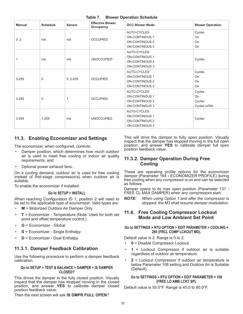
Table 7. Blower Operation Schedule
Manual Schedule Sensor Effective Blower Occupancy OCC Blower Mode Blower Operation
0, 2 n/a n/a OCCUPIED
AUTO-CYCLESON-CONTINOUS 1ON-CONTINOUS 2ON-CONTINOUS 3
CyclesOnOnOn
1 n/a n/a UNOCCUPIED
AUTO-CYCLESON-CONTINOUS 1ON-CONTINOUS 2ON-CONTINOUS 3
Cycles
3 -255 0 0, 2-255 OCCUPIED
AUTO-CYCLESON-CONTINOUS 1ON-CONTINOUS 2ON-CONTINOUS 3
CyclesOnOnOn
3 -255 0 1 OCCUPIED
AUTO-CYCLESON-CONTINOUS 1ON-CONTINOUS 2ON-CONTINOUS 3
CyclesOnCyclesCycles w/Stir
3 -255 1-255 n/a UNOCCUPIED
AUTO-CYCLESON-CONTINOUS 1ON-CONTINOUS 2ON-CONTINOUS 3
Cycles
11.3. Enabling Economizer and Settings Theeconomizer,whenconfigured,controls:• Damper position, which determines how much outdoor
air is used to meet free cooling or indoor air quality requirements, and
• Optional power exhaust fans.On a cooling demand, outdoor air is used for free cooling instead of first-stage compressor(s) when outdoor air issuitable.To enable the economizer if installed:
Go to SETUP > INSTALL When reachingConfiguration ID1, position2will need tobe set to the applicable type of economizer. Valid types are:• M = Motorized Outdoor Air Damper Only• T = Economizer - Temperature (Note: Used for both set
point and offset temperature control.)• G = Economizer - Global• S = Economizer - Single Enthalpy• D = Economizer - Dual Enthalpy
11.3.1. Damper Feedback CalibrationUse the following procedure to perform a damper feedback calibration.
Go to SETUP > TEST & BALANCE > DAMPER > IS DAMPER CLOSED?
This drives the damper to the fully closed position. Visually inspect that the damper has stopped moving in the closed position, and answer YES to calibrate damper closed position feedback value.Then the next screen will ask IS DMPR FULL OPEN?
This will drive the damper to fully open position. Visually inspect that the damper has stopped moving in the full open position, and answer YES to calibrate damper full open position feedback value.
11.3.2. Damper Operation During Free Cooling
These are operating profile options for the economizerdamper (Parameter 164 - ECONOMIZER PROFILE) during free cooling when any compressor is on and can be selected as follows:Damper opens to its max open position (Parameter 131 - FREE CL MAX DAMPER) when any compressors start.NOTE: When using Option 1 and after the compressor is
stopped, the M3 shall resume damper modulation.
11.4. Free Cooling Compressor Lockout Mode and Low Ambient Set Point
Go to SETTINGS > RTU OPTION > EDIT PARAMETER > COOLING = 285 (FRCL COMP LCKOUT MD).
Default value is 2. Range is 0 to 2.• 0 = Disable Compressor Lockout• 1 = Lockout Compressor if outdoor air is suitable
regardless of outdoor air temperature.• 2 = Lockout Compressor if outdoor air temperature is
below Parameter 108 setting and Outdoor Air is Suitable (Default).
Go to SETTINGS > RTU OPTION > EDIT PARAMETER = 108 (FREE LO AMB LCKT SP).
Default value is 55.0°F. Range is 45.0 to 80.0°F.
33
11.4.1. Outdoor Air Suitable for Free Cooling
The CORE Unit Controller displays the outdoor air suitability information on the status screen. The appropriate sensors are provided when the economizer isfactory-configured.Whentheeconomizerisfield-installedandconfigured, thesingleordualenthalpymodes requireadditionalfield-providedsensor(s).
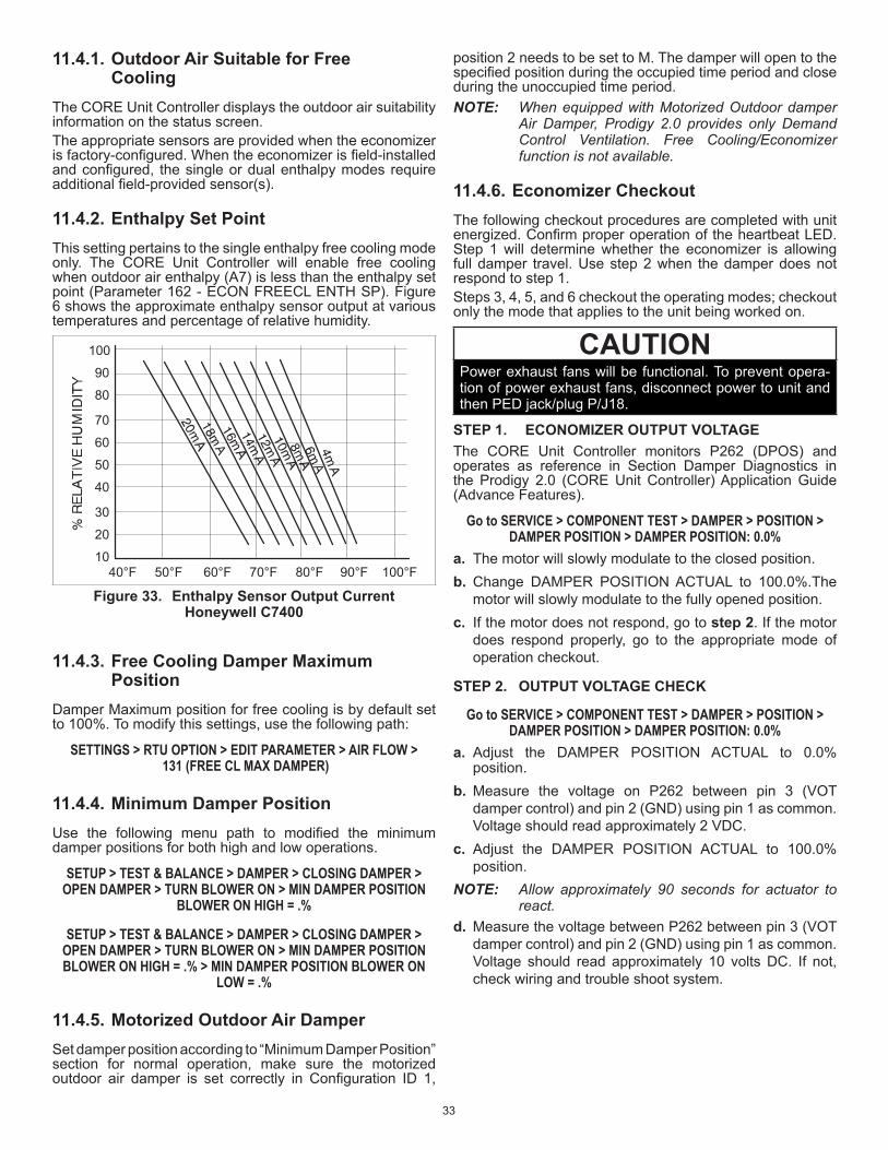
11.4.2. Enthalpy Set Point This setting pertains to the single enthalpy free cooling mode only. The CORE Unit Controller will enable free cooling when outdoor air enthalpy (A7) is less than the enthalpy set point (Parameter 162 - ECON FREECL ENTH SP). Figure 6 shows the approximate enthalpy sensor output at various temperatures and percentage of relative humidity.
40°F 50°F 60°F 70°F 80°F 90°F 100°F
30
20
10
40
50
60
70
80
90
100
Figure 33. Enthalpy Sensor Output Current Honeywell C7400
11.4.3. Free Cooling Damper Maximum Position
Damper Maximum position for free cooling is by default set to 100%. To modify this settings, use the following path:
SETTINGS > RTU OPTION > EDIT PARAMETER > AIR FLOW > 131 (FREE CL MAX DAMPER)
11.4.4. Minimum Damper Position Use the following menu path to modified the minimumdamper positions for both high and low operations.
SETUP > TEST & BALANCE > DAMPER > CLOSING DAMPER > OPEN DAMPER > TURN BLOWER ON > MIN DAMPER POSITION
BLOWER ON HIGH = .%
SETUP > TEST & BALANCE > DAMPER > CLOSING DAMPER > OPEN DAMPER > TURN BLOWER ON > MIN DAMPER POSITION BLOWER ON HIGH = .% > MIN DAMPER POSITION BLOWER ON
LOW = .%
11.4.5. Motorized Outdoor Air Damper Set damper position according to “Minimum Damper Position” section for normal operation, make sure the motorized outdoor air damper is set correctly in Configuration ID 1,
position 2 needs to be set to M. The damper will open to the specifiedpositionduringtheoccupiedtimeperiodandcloseduring the unoccupied time period.NOTE: When equipped with Motorized Outdoor damper
Air Damper, Prodigy 2.0 provides only Demand Control Ventilation. Free Cooling/Economizer function is not available.
11.4.6. Economizer Checkout The following checkout procedures are completed with unit energized.ConfirmproperoperationoftheheartbeatLED.Step 1 will determine whether the economizer is allowing full damper travel. Use step 2 when the damper does not respond to step 1.Steps 3, 4, 5, and 6 checkout the operating modes; checkout only the mode that applies to the unit being worked on.
CAUTIONPower exhaust fans will be functional. To prevent opera-tion of power exhaust fans, disconnect power to unit and then PED jack/plug P/J18.
STEP 1. ECONOMIZER OUTPUT VOLTAGEThe CORE Unit Controller monitors P262 (DPOS) and operates as reference in Section Damper Diagnostics in the Prodigy 2.0 (CORE Unit Controller) Application Guide (Advance Features).
Go to SERVICE > COMPONENT TEST > DAMPER > POSITION > DAMPER POSITION > DAMPER POSITION: 0.0%
a. The motor will slowly modulate to the closed position.b. Change DAMPER POSITION ACTUAL to 100.0%.The
motor will slowly modulate to the fully opened position.c. If the motor does not respond, go to step 2. If the motor
does respond properly, go to the appropriate mode of operation checkout.
STEP 2. OUTPUT VOLTAGE CHECK
Go to SERVICE > COMPONENT TEST > DAMPER > POSITION > DAMPER POSITION > DAMPER POSITION: 0.0%
a. Adjust the DAMPER POSITION ACTUAL to 0.0% position.
b. Measure the voltage on P262 between pin 3 (VOT damper control) and pin 2 (GND) using pin 1 as common. Voltage should read approximately 2 VDC.
c. Adjust the DAMPER POSITION ACTUAL to 100.0% position.
NOTE: Allow approximately 90 seconds for actuator to react.
d. Measure the voltage between P262 between pin 3 (VOT damper control) and pin 2 (GND) using pin 1 as common. Voltage should read approximately 10 volts DC. If not, check wiring and trouble shoot system.

34
STEP 3. SINGLE ENTHALPY OPERATION (ODE)In the single enthalpy mode, dampers open for free cooling when the outdoor enthalpy is less than the enthalpy set point (Parameter 162 - ECON FREECL ENTH SP); dampers will try to modulate discharge air temperature (RT6) to (Parameter 159 - FREE COOL SUPPLY SP) which has a default setting of 55.0°F (13°C).a. Go to SETUP > INSTALL > press SAVEuntilyouget to theConfiguration ID1,position2needs tobeset toS for
Economizer Single Enthalpy and press SAVE.b. To simulate low outdoor enthalpy. Disconnect A7 outdoor enthalpy sensor jack/plugs J/P104. Connect a 750 ohm resistor
acrossplugJ104-1andJ104-2.J104islocatedinthefilteraccessarea.c. Check all connections and wiring between J104 and the control.
STEP 4. DUAL ENTHALPY MODE OF OPERATIONIn dual enthalpy mode, dampers open for free cooling when the outdoor air enthalpy is lower than the return air enthalpy by difference value of (Parameter 163 - ECN FRCL ENTH OFFST); dampers will modulate discharge air temperature (RT6) to (Parameter 159 - FREE COOL SUPPLY SP) which has a default setting of 55.0°F (13°C).a. Go to SETUP > INSTALL > press NEXTuntilyouget to theConfiguration ID1position2needs tobeset toD for
EconomizerDualEnthalpyandpressSAVEifperforminganeconomizerfield-install.b. Use two resistors to simulate outdoor air enthalpy suitable. c. Disconnect A62 return air enthalpy sensor jack/plug
J/P105.Placea1500ohmresistorbetweenJ105-1andJ105-3.J/P105islocatedinthefilteraccessarea.d. Disconnect A7 outdoor enthalpy sensor jack/plugs J/P104. Connect a 750 ohm resistor across J104-1 and J104-2.
STEP 5. ALL TEMPERATURE MODES OF OPERATIONIn the Economizer – Temperature mode, the damper opens for free cooling when the outdoor air temperature is:• Less than return air temperature by at least a difference of (Parameter 161 - ECON FRCL TMP OFFST) if Temperature
Offset mode is selected• Less than (Parameter 160 - ECON FREECL TEMP SP)In all modes, dampers will try to modulate discharge air temperature (RT6) to (Parameter 159 - FREE COOL SUPPLY SP) which has a default setting of 55.0°F (13°C).Refer to the “Displaying Sensor Inputs” section to read return air (RT16) and outdoor air (RT17) temperatures. If outdoor air is not cooler than return air, simulate a colder outdoor air temperature with a resistor. Select a resistor value that corresponds to a temperature:a. Locate RT17 sensor in unit. Disconnect 1/4” quick connect terminals on wires leading from sensor.b. Jumper RT17 wires leading back to control with the appropriate resistor.c. Check all connections and wiring between RT17 and the CORE Unit Controller, and between RT16 and the CORE Unit
Controller.
Table 8. TMP Mode Resistor ValuesTemp. °F
(°C)Size
ResistorTemp. °F
(°C)Size
ResistorTemp. °F
(°C)Size
ResistorTemp. °F
(°C)Size
Resistor
30 (-1) 34,566 50 (10) 19,904 70 (21) 11,884 90 (32) 7,332
40 ( 4) 26,106 60 (16) 15,313 80 (27) 9,298 100 (38) 5,826
DISCONNECT J/P104
PLACE JUMPER WIRE HERE
READCURRENTHERE
DC AMMETER- +
Damper Travel: % of Maximum Open
DISCONNECT J/P105
PLACE JUMPER WIRE HERE
READCURRENTHERE
DC AMMETER- +
Measure A62 Current in SeriesMeasure A7 Current in Series
Figure 34. Measure A7 and A62 Current in Series

35
STEP 6. GLOBAL MODULATING (GLO) MODE OF OPERATIONIn the GLO (modulating) mode, dampers modulate open for free cooling when the global input is energized; dampers will try to modulate discharge air temperature (RT6) to (Parameter 159 - FREE COOL SUPPLY SP) which has a default setting of 55.0°F (13°C).NOTE: The global input turns on the blower.a. SetglobalmodeusingtheConfigurationID1,position2,andsettocharacterG.b. Connect a jumper between A55_P297-1 (24VAC) and A55_P297-9 (global). The blower is energized and the damper will
slowly open if discharge air temperature (RT6) is greater than (Parameter 159 - FREE COOL SUPPLY SP) which has a default setting of 55.0°F (13°C).
c. Disconnect 24VAC to A55_P297-9. The blower will turn off and the damper will close.d. If the damper does not actuate then check all connections and wiring between P262A and B.
STEP 7. ENTHALPY SENSOR OPERATION (A7 AND A62)Ifenthalpysensorsareconfigured,currentsensorreadingbyCOREUnitControllercanbeverifiedthroughtheuserinterface:a. Connectadirectcurrentammeterasshowninfigure4tomeasurecurrentoutputofA7orA62.b. Thereadingwillbebetween(4and20ma.)anddependsonoutdoor temperatureandhumidity.Refer tofigure3to
approximate reading.
Go to DATA > SYSTEM DATA / SENSORS / OUTPUTS > LOCAL INPUTS > SENSORS > LOCAL (scroll down to INDOOR AND OUTDOOR ENTHALPY)
c. If the meter reads zero, check sensor wiring harness for continuity and/or check polarity of sensor wiring.
11.5. Demand Control Ventilation Afield-providedand installed indoorairquality (IAQ)sensorcanbeusedwith themodulatingeconomizerorOADMtocontrol carbon dioxide levels in the conditioned space. The carbon dioxide level in a space is an indicator of the number of people occupying a room. As the carbon dioxide level rises (indicating the occupancy of a room has increased), dampers modulate open - regardless of outdoor air suitability. Likewise, as the carbon dioxide level falls (indicating the occupancy has decreased), dampers modulate further closed.Standard economizer installations have a minimum fresh air ventilation requirement based on maximum room occupancy. With standard economizer use, the amount of air required for maximum room occupancy is heated or cooled with each heating or cooling cycle. IAQ installations use the maximum amount of required ventilation air only with maximum room occupancy; less outdoor air needs to be heated or cooled when fewer people are in the conditioned space. If the economizer is operating in the free cooling mode and the indoor air quality control requires the damper to open further, the indoor air quality demand will override the free cooling demand. The IAQ function is not energized during the unoccupied or night time period.NOTE: The IAQ sensor may also be used with systems containing a motorized outdoor air damper.
11.5.1. Default Operation The CORE Unit Controller has a 0-10VDC indoor air quality input for a standard 0 - 2000ppm carbon dioxide sensor. The economizer starts opening at a carbon dioxide level of 700 ppm (default) (start open set point) and reaches full open at a carbon dioxide level of 1200ppm (default) (full open set point). The damper opens to a default position of 50% (see Parameter 117). Determine damper travel position using the following formula:
% Damper Travel = carbon dioxide ppm - Start Open ppm5
Example: At a carbon dioxide level of 750ppm, the damper will be approximately 50% open:% Damper Travel = 750-500 = 50%
5Use the menu interface to read carbon dioxide ppm.
Go to DATA > SYSTEM DATA / SENSORS / OUTPUTS > LOCAL INPUTS > SENSORS > LOCAL (scroll down to CO2)
11.5.2. Maximum and Minimum Demand Control Ventilation Damper Settings Maximum position is set using the following menu path:
Go to SETTINGS > RTU OPTIONS > DAMPER > SET ECONOMIZER OPTION > SET FREE COOLING SUPPLY AIR SETPOINT > CLOSE DAMPER > OPEN DAMPER > TURN ON BLOWER > MINIMUM DAMPER POSITION > and select DEMAND CONTROL VENTILATION.
36
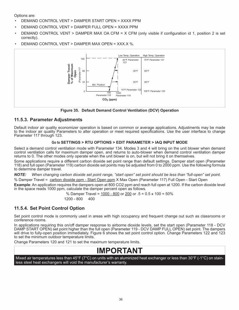
Options are:• DEMAND CONTROL VENT > DAMPER START OPEN = XXXX PPM• DEMAND CONTROL VENT > DAMPER FULL OPEN = XXXX PPM• DEMANDCONTROLVENT>DAMPERMAXOACFM=XCFM(onlyvisible ifconfiguration id1,position2 isset
correctly).• DEMAND CONTROL VENT > DAMPER MAX OPEN = XXX.X %.
33
66
100
700Parameter 118
1000Parameter 119
Low Temp. Operation High Temp. Operation
CO2 (ppm)
10°F Parameter 122
20°F
30°F
40°F Parameter123
105°F Parameter 120
95°F
85°F
75°F Parameter 121
0
Min. PositionDam
per T
rave
l:%
of M
axim
umO
pen
(Par
amet
er 1
17
Figure 35. Default Demand Control Ventilation (DCV) Operation
11.5.3. Parameter Adjustments Default indoor air quality economizer operation is based on common or average applications. Adjustments may be made to the indoorairqualityParameters toalteroperationormeetrequiredspecifications.Usetheuser interfacetochangeParameter 117 through 123.
Go to SETTINGS > RTU OPTIONS > EDIT PARAMETER > IAQ INPUT MODESelect a demand control ventilation mode with Parameter 134. Modes 3 and 4 will bring on the unit blower when demand control ventilation calls for maximum damper open, and returns to auto-blower when demand control ventilation damper returns to 0. The other modes only operate when the unit blower is on, but will not bring it on themselves.Some applications require a different carbon dioxide set point range than default settings. Damper start open (Parameter 118) and full open (Parameter 119) carbon dioxide set points may be adjusted from 0 to 2000 ppm. Use the following formula to determine damper travel.NOTE: When changing carbon dioxide set point range, “start open” set point should be less than “full-open” set point.% Damper Travel = carbon dioxide ppm - Start Open ppm X Max Open (Parameter 117) Full Open - Start Open Example: An application requires the dampers open at 800 CO2 ppm and reach full open at 1200. If the carbon dioxide level in the space reads 1000 ppm, calculate the damper percent open as follows.
% Damper Travel = 1000 - 800 or 200 or .5 = 0.5 x 100 = 50% 1200 - 800 400
11.5.4. Set Point Control OptionSet point control mode is commonly used in areas with high occupancy and frequent change out such as classrooms or conference rooms. In applications requiring this on/off damper response to airborne dioxide levels, set the start open (Parameter 118 - DCV DAMP START OPEN) set point higher than the full open (Parameter 119 - DCV DAMP FULL OPEN) set point. The dampers will drive to fully-open position immediately. Figure 6 shows the set point control option. Change Parameters 122 and 123 to set the minimum outdoor temperature limits. Change Parameters 120 and 121 to set the maximum temperature limits.
IMPORTANTMixed air temperatures less than 45°F (7°C) on units with an aluminized heat exchanger or less than 30°F (-1°C) on stain-less steel heat exchangers will void the manufacturer’s warranty.

37
Min. Position
100 Parameter 117
Parameter 119(full)
Parameter 118(start)
carbon dioxide (ppm)
Max. Open
Close Open
Figure 36. Set point Control Indoor Air Quality Option
11.6. Determining Indoor Air Quality InputsSelection from the CORE Unit Controller menu display.
Go to DATA > SYSTEM DATA / SENSORS / OUTPUTS > LOCAL INPUTS > SENSORS
11.7. BACNET• Theconfigurationshowninfigure37hasterminationsontheCOREUnitControllerBACnetmodulesatbothendsand
ONLY at both ends of the chain.• Theconfigurationshowntotheinfigure37hasaterminationatthecontroller/routerononeendandaterminationatthe
CORE Unit Controller BACnet module on the other end; terminations are ONLY at the ends of the chain.• Cable type - twisted pair with shield, 22 awg minimum, Belden #88761 or #8761 (Lennox 27M19, 94L63, 68M35).
(terminated)(terminated) (not terminated) (not terminated)
CONTROLLER/ROUTER
minated)ated)
(not terminated)
(terminated per mfginstructions)
The configuration shown above has terminations on theunit controller BACnet modules at both ends and ONLYat both ends of the chain.The configuration shown to the right has a termination atthe controller/router on one end and a termination at the
ations are ONLY at the ends of the chain.Cable type - twisted pair with shield, 22 awg minimum,Belden #88761 or #8761 (Lennox 27M19, 94L63, 68M35).
CONTROLLER/ROUTER
(not terminated) (terminated)
minated)
Figure 37. Terminating Ends of a Daisy-Chained Network

38
11.8. Abbreviations
Table 9. AbbreviationsAbbreviation Definition
A55 M3 board. Main RTU control board
AI Analog input
AO Analog output
BL Blower
C3 Add on board for third and fourth compressor and second-stage heat (A178).
C1 1st stage cooling
C2 2nd stage cooling
C3 3rd stage cooling
C4 4th stage cooling
CAI Combustion air inducer
CAVB Constant air volume with bypass damper
COM Electrical common
CL Cooling
CP1 Compressor 1
CP2 Compressor 2
CP3 Compressor 3
CP4 Compressor 4
CSP Cooling setpoint
DAC Discharge (supply) air control
DACC Discharge (supply) air control cooling
DACH Discharge (supply) air control heating
DAP Discharge (supply) air pressure
DAT Discharge (supply) air temperature
DB Deadband
DCV Demand controlled ventilation
DDC Direct digital control
DI Digital input
Diff Differential
DO Digital output
FAC Fresh air cooling control
FAH Fresh air heating control
FAT Fresh air tempering control. See FAC & FAH
FC Free cooling
G Thermostat demand, blower
GLO Global mode or input (economizer)
H1 1st stage heating
H2 2nd stage heating
H3 3rd stage heating
H4 4th stage heating
HP High pressure
HSP Heating setpoint
HT Heating
IAQ Indoor air quality. Often synonymous with CO2 level in ppm
IDE Indoor enthalpy. Depends on temperature and humidity
“w.c. Inches of water column
Table 9. AbbreviationsAbbreviation Definition
LED Light emitting diode. An indicator light, found either as individual elements or grouped together as segments to form characters
LP Low pressure
LT Limit
M4 CORE Unit Controller - main controller board (A55)
MGV Modulating gas valve
MSAV Multi Stage Air Volume
OAC Outdoor air control
OAS Outdoor air suitable for free cooling
OAT Outdoor air temperature
OCP Thermostat demand, occupied mode
ODE Outdoor enthalpy. Depends on temperature and humidity
PID Proportional, integral and derivative based control loop
PPM Parts per million (mostly used for CO2 measurements)
RAP Return air pressure
RAT Return air temperature
RH Relative humidity
RS Reset
RTU Roof top unit
RT6 Discharge air temperature sensor
RT16 Return air temperature sensor
RT17 Outdoor air temperature sensor
SMK Smoke detection mode (alarm)
SP Setpoint
Stg Stage
TB Terminal block
UnOCP Unoccupied
W1 Thermostat demand, heat stage 1
W2 Thermostat demand, heat stage 2
W3 Thermostat demand, heat stage 3
W4 Thermostat demand, heat stage 4
VAC Alternating current voltage
VAV Variable air volume. Accomplished with a variable frequency drive (VFD)
VDC Direct current voltage
VFD Var. frequency drive. An AC inverter used to vary motor speed
VT Ventilation
Y1 Thermostat demand, cooling stage one
Y2 Thermostat demand, cooling stage two
Y3 Thermostat demand, cooling stage three
Y4 Thermostat demand, cooling stage four
ZAT Zone air temperature

39
12. Parts and KitsTable 10. Parts and Kits Available for CORE Unit Controller
Description Catalog number Description Catalog number Description Catalog numberCORE Unit Controller Replacement kit
14V60 USB service kit tube 59W52 SmartWire™ Field Termination kit
59W57
LCD Display Replacement Kit
10X85 CORE Unit Controller battery (10-pack)
59W53 Lennox Prodigy 2.0 USB Memory Stick (5-pack)
59W59
CORE Unit Controller cover 10X86 BACnet Replacement kit 59W51
13. Service Report Example===================================================USB SERVICE REPORT===================================================Service Date 04:03:2014Service Time 19:26:35Serial No.Software Version 08.00.0009Hardware VersionUnit Number UNIT 1SBUS Address 2BACnet Address 2Catalogue NumberModel Number LGH060H4EH1YCONFIGURATION ID 1 NTNNNNLNCONFIGURATION ID 2 NNNNNNNNNStatus IDLE===================================================Runtime Data Total Power On 23 HRS 8 CYCLES Before Install 0 HRS −−−−−−− Filter 12 HRS −−−−−−− Belt 11 HRS −−−−−−− Blower 12 HRS 50 CYCLES Compressor 1 3 HRS 40 CYCLES Compressor 2 4 HRS 27 CYCLES Compressor 3 0 HRS 2 CYCLES Compressor 4 0 HRS 3 CYCLES Outdoor Fan 1 7 HRS 28 CYCLES Outdoor Fan 2 2 HRS 22 CYCLES Outdoor Fan 3 0 HRS 2 CYCLES Outdoor Fan 4 0 HRS 3 CYCLES Outdoor Fan 5 0 HRS 3 CYCLES Outdoor Fan 6 0 HRS 3 CYCLES POWER EXHAUST 0 HRS 0 CYCLES Heat Stage 1 0 HRS 1 CYCLES Heat Stage 2 0 HRS 1 CYCLES Humiditrol 0 HRS 0 CYCLES Free Cooling 0 HRS 4 CYCLES UV Lamp 0 HRS −−−−−−−===================================================Sensor Data OAT 66 degF RAT 72 degF DAT 73 degF ZAT 78 degF RH 50 % CO2 460 ppm===================================================SmartAirFlow System Data
Calibrated On 04/03/2014 19:12:56
Supply Airflow Calibration Table −−−−−−−−−−−−−−−−−−−−−−−−−−−−−−−−−−−−−− PWM(%) Speed(rpm) Airflow(cfm) −−−−−−−−−−−−−−−−−−−−−−−−−−−−−−−−−−−−−− 20 480 1031 30 570 1274 40 660 1493 50 750 1687 60 840 1857 70 930 2004 80 1020 2126 90 1110 2223 100 1200 2297
Supply Airflow Targets −−−−−−−−−−−−−−−−−−−−−−−−−−−−−−−−−−−−−−−−−−−−−−−− Mode Desired Airflow(cfm) PWM(%) −−−−−−−−−−−−−−−−−−−−−−−−−−−−−−−−−−−−−−−−−−−−−−−−
Cool High 1800 57 Cool Low 1300 31 Heat 2000 70 Ventilation 1200 27 Smoke 2000 70Economizer Differential Pressure(@ 2000 SupplyAirflow(cfm))−−−−−−−−−−−−−−−−−−−−−−−−−−−−−−−−−−−−−−−−−−−−−−−− Damper Position (%) Diff.Pressure(in.H20) −−−−−−−−−−−−−−−−−−−−−−−−−−−−−−−−−−−−−−−−−−−−−−−− 0 0.39 50 0.23 100 0.06 Outside Airflow Targets −−−−−−−−−−−−−−−−−−−−−−−−−−−−−−−−−−−−−−−−−−−− Minimum Outside Air/Minimum DCV: 200 cfm Maximum DCV: 0 cfm Minimum CO2: 700 ppm Maximum CO2: 1200 ppm===================================================Alarm/Status Log (143) 04:03:2014 19:26:13 RESET DAMPER PRESSURE (141) 04:03:2014 19:26:13 RESET CFM TARGET TOOHIGH (143) 04:03:2014 19:06:19 SET DAMPER PRESSURE (141) 04:03:2014 19:06:19 SET CFM TARGET TOOHIGH ( 82) 04:03:2014 19:06:18 RESET CONTROLLER RESET ( 82) 04:03:2014 19:06:18 SET CONTROLLER RESET (143) 04:03:2014 18:59:41 SET DAMPER PRESSURE (141) 04:03:2014 18:59:41 SET CFM TARGET TOOHIGH ( 82) 04:03:2014 18:59:40 RESET CONTROLLER RESET ( 82) 04:03:2014 18:59:40 SET CONTROLLER RESET (143) 04:03:2014 18:35:19 SET DAMPER PRESSURE (141) 04:03:2014 18:35:19 SET CFM TARGET TOOHIGH (148) 04:03:2014 18:21:36 RESET SMART AIRFLOWCONFIG ERROR (170) 04:03:2014 18:21:36 RESET POWER EXHAUSTUNCONFIGURED (165) 04:03:2014 18:21:36 RESET ECONOMIZERUNCONFIGURED ( 85) 04:03:2014 18:21:36 RESET INCORRECTHUMIDITROL SETTINGS (132) 04:03:2014 18:21:24 RESET VFD BYPASSUNCONFIGURED (148) 04:03:2014 18:21:23 SET SMART AIRFLOWCONFIG ERROR (132) 04:03:2014 18:21:23 SET VFD BYPASSUNCONFIGURED (170) 04:03:2014 18:21:23 SET POWER EXHAUSTUNCONFIGURED (165) 04:03:2014 18:21:23 SET ECONOMIZERUNCONFIGURED ( 85) 04:03:2014 18:21:23 SET INCORRECTHUMIDITROL SETTINGS ( 82) 04:03:2014 18:20:31 RESET CONTROLLER RESET ( 82) 04:03:2014 18:20:31 SET CONTROLLER RESET ( 82) 04:03:2014 18:16:32 RESET CONTROLLER RESET ( 82) 04:03:2014 18:16:32 SET CONTROLLER RESET ( 82) 04:03:2014 18:14:10 RESET CONTROLLER RESET ( 82) 04:03:2014 18:14:10 SET CONTROLLER RESET ( 82) 04:03:2014 18:14:09 RESET CONTROLLER RESET ( 82) 04:03:2014 18:14:09 SET CONTROLLER RESET
=====================================================END OF REPORT
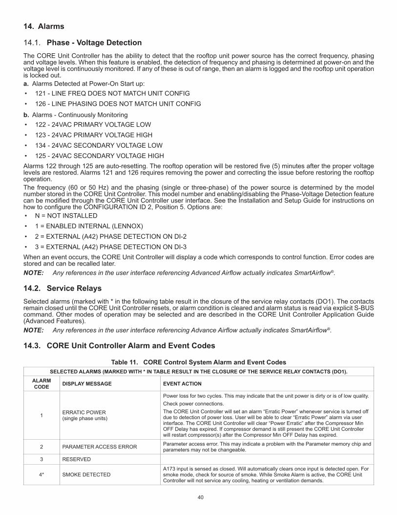
40
14. Alarms
14.1. Phase - Voltage DetectionThe CORE Unit Controller has the ability to detect that the rooftop unit power source has the correct frequency, phasing and voltage levels. When this feature is enabled, the detection of frequency and phasing is determined at power-on and the voltage level is continuously monitored. If any of these is out of range, then an alarm is logged and the rooftop unit operation is locked out.a. Alarms Detected at Power-On Start up:• 121 - LINE FREQ DOES NOT MATCH UNIT CONFIG• 126 - LINE PHASING DOES NOT MATCH UNIT CONFIG
b. Alarms - Continuously Monitoring• 122 - 24VAC PRIMARY VOLTAGE LOW• 123 - 24VAC PRIMARY VOLTAGE HIGH• 134 - 24VAC SECONDARY VOLTAGE LOW• 125 - 24VAC SECONDARY VOLTAGE HIGHAlarms122through125areauto-resetting.Therooftopoperationwillberestoredfive(5)minutesafterthepropervoltagelevels are restored. Alarms 121 and 126 requires removing the power and correcting the issue before restoring the rooftop operation.The frequency (60 or 50 Hz) and the phasing (single or three-phase) of the power source is determined by the model number stored in the CORE Unit Controller. This model number and enabling/disabling the Phase-Voltage Detection feature canbemodifiedthroughtheCOREUnitControlleruserinterface.SeetheInstallationandSetupGuideforinstructionsonhowtoconfiguretheCONFIGURATIONID2,Position5.Optionsare:• N = NOT INSTALLED• 1 = ENABLED INTERNAL (LENNOX)• 2 = EXTERNAL (A42) PHASE DETECTION ON DI-2• 3 = EXTERNAL (A42) PHASE DETECTION ON DI-3When an event occurs, the CORE Unit Controller will display a code which corresponds to control function. Error codes are stored and can be recalled later. NOTE: Any references in the user interface referencing Advanced Airflow actually indicates SmartAirflow®.
14.2. Service RelaysSelected alarms (marked with * in the following table result in the closure of the service relay contacts (DO1). The contacts remain closed until the CORE Unit Controller resets, or alarm condition is cleared and alarm status is read via explicit S-BUS command. Other modes of operation may be selected and are described in the CORE Unit Controller Application Guide (Advanced Features).NOTE: Any references in the user interface referencing Advance Airflow actually indicates SmartAirflow®.
14.3. CORE Unit Controller Alarm and Event Codes
Table 11. CORE Control System Alarm and Event CodesSELECTED ALARMS (MARKED WITH * IN TABLE RESULT IN THE CLOSURE OF THE SERVICE RELAY CONTACTS (DO1).
ALARM CODE DISPLAY MESSAGE EVENT ACTION
1 ERRATIC POWER (single phase units)
Power loss for two cycles. This may indicate that the unit power is dirty or is of low quality.Check power connections.The CORE Unit Controller will set an alarm “Erratic Power” whenever service is turned off due to detection of power loss. User will be able to clear “Erratic Power” alarm via user interface. The CORE Unit Controller will clear “Power Erratic” after the Compressor Min OFF Delay has expired. If compressor demand is still present the CORE Unit Controller will restart compressor(s) after the Compressor Min OFF Delay has expired.
2 PARAMETER ACCESS ERROR Parameter access error. This may indicate a problem with the Parameter memory chip and parameters may not be changeable.
3 RESERVED
4* SMOKE DETECTEDA173 input is sensed as closed. Will automatically clears once input is detected open. For smoke mode, check for source of smoke. While Smoke Alarm is active, the CORE Unit Controller will not service any cooling, heating or ventilation demands.

41
Table 11. CORE Control System Alarm and Event CodesSELECTED ALARMS (MARKED WITH * IN TABLE RESULT IN THE CLOSURE OF THE SERVICE RELAY CONTACTS (DO1).
ALARM CODE DISPLAY MESSAGE EVENT ACTION
5* BLOWER - NO AIR FLOW DETECTED
Unitoff.Airflowswitchisnormallyclosed.Monitoringstarts16secondsafterblowerisstarted.ifairflowswitchisdetectedopenafter16seconddelayperiod,allcompressorsare de-energized, gas valves closed, electric heat turned off, economizer damper closed, and blower is stopped. Alarm will automatically clear once the error timed off delay has expired and system will resume. Check blower operation.
6* DIRTY AIR FILTER Dirtyfilterswitchisdetectedasclosedandwillautomaticallyclearonceswitchisdetectedopen.ReplacefilterorcheckfilterswitchS27.
7 EXTERNAL EEPROM WRITE ERROR
8* STRIKE 3 ON BLOWERLockout is active with multiple alarm code 5 detected. Alarm can be manually cleared through the user interface. Check blower operation. Once problem is corrected, lockout alarm can be cleared by resetting the CORE Unit Controller.
9 RESERVED
10 24VAC POWER LOSS TB35-1 24 VAC power loss at TB35-1 on A55 (M1) board. P111 pin 11.
11 24VAC POWER LOSS TB34-1 24 VAC power loss at TB34-1 on A55 (M1) board. P113 pin 1.
12 HIGH PRESS S4 OPEN COMP1
Compressor is off. Check charge, fans and coil.NOTE: On Ultra-High Efficiency units - if only alarm 12 is present then issue could be high
temperature S5 switch. If alarm 12 is accompanied with alarm 14 then most likely it is the high pressure S4 switch.
The unit controller will clear high pressure switch alarm when corresponding high pressure switch is detected as closed. Compressor will not restart until corresponding high pressure switch is closed and Minimum Off Delay (cooling or heating) has expired.
13* STRIKE3 HIGH PRESS S4 OPEN COMP1
• Compressor is lockout. Check charge, fans and coil. Use service menu to clear lockouts.
• User will be able to clear high pressure switch compressor lockout and alarm via user interface. High pressure switch compressor lockout and alarm will be cleared after the CORE Unit Controller reset.
• High pressure switch compressor lockout and alarm will be cleared on termination of cooling demand.
• Default is 3 occurrences and can be set between 1 and 7 occurrences.
14 HIGH PRESS S7 OPEN COMP2
Compress is off. Check charge, fans or coil. This feature is not support in Model L at this time.NOTE: On Ultra-High efficiency units tandem alarms (14) compressor 2 high temperature
S8 switch. If accompanied with alarm 15 then most likely the S4 high pressure switch is the issue.
The CORE Unit Controller will clear high pressure switch alarm when corresponding high pressure switch is detected as closed. Compressor will not be restarted until corresponding high pressure switch is closed and Minimum Off Delay (cooling or heating) has expired.
15* STRIKE3 HIGH PRESS S7 OPEN COMP2
• Compressor lockout. Check charge, fans and coil. Use service menu to clear lockouts.
• User will be able to clear high pressure switch compressor lockout and alarm via user interface. High pressure switch compressor lockout and alarm will be cleared after the CORE Unit Controller reset.
• High pressure switch compressor lockout and alarm will be cleared on removal of cooling demand.
• Default is 3 occurrences and can be set between 1 and 7 occurrences.
16 HIGH PRESS S28 OPEN COMP3
• Compressor is off. Check charge, fans and coil.
• The CORE Unit Controller will clear high pressure switch alarm when corresponding high pressure switch is detected as closed. Compressor will not be restarted until corresponding high pressure switch is closed and Minimum Off Delay (cooling or heating) has expired.
17* STRIKE3 HIGH PRESS S28 OPEN COMP3
• Compressor lockout. Check charge, fans and coil. Use CORE Service application RTU > SERVICE menu to clear lockouts.
• User will be able to clear high pressure switch compressor lockout and alarm through the user interface. High pressure switch compressor lockout and alarm will be cleared after the CORE Unit Controller reset.
• High pressure switch compressor lockout and alarm is cleared on removal of cooling demand. Default is 3 occurrences and can be set between 1 and 7 occurrences.

42
Table 11. CORE Control System Alarm and Event CodesSELECTED ALARMS (MARKED WITH * IN TABLE RESULT IN THE CLOSURE OF THE SERVICE RELAY CONTACTS (DO1).
ALARM CODE DISPLAY MESSAGE EVENT ACTION
18 HIGH PRESS S96 OPEN COMP4
• Compressor lockout. Check charge, fans and coil.
• The CORE Unit Controller will clear high pressure switch alarm when corresponding high pressure switch is detected as closed. Compressor will not be restarted until corresponding high pressure switch is closed and Minimum Off Delay (cooling or heating) has expired.
19* STRIKE3 HIGH PRESS S96 OPEN COMP4
• Compressor lockout. Check charge, fans and coil. Use service menu to clear lockouts.
• User will be able to clear high pressure switch compressor lockout and alarm via user interface. High pressure switch compressor lockout and alarm will be cleared after the CORE Unit Controller reset.
• High pressure switch compressor lockout and alarm is cleared on removal of cooling demand. Default is 3 occurrences and can be set between 1 and 7 occurrences.
NOTE: EVENTS 12 THROUGH 19 COULD ALSO BE CAUSED BY A HIGH TEMPERATURE CONDITION ON SOME COMPRESSORS EQUIPPED WITH A HIGH TEMPERATURE SHUTDOWN.
20 PHASE MONITOR FAULT Phase monitor or blower motor overload switch or inverter fault output or condensate overflowswitchisindicatinganissue.
21 STRIKE 3 PHASE MONITOR FAULT
22 LOW PRESS S87 OPEN COMP1 Compressor is off. Check charge, fans and coil. Use service menu to clear lockouts.
23* STRIKE3 LOW PRESS S87 OPEN COMP1
• Compressor is off. Check charge, fans and coil. Use service menu to clear lockouts.
• Number of occurrences is set using Parameter 99 (max lo occurrences). Default is 3 occurrences.
24 LOW PRESS S88 OPEN COMP Compressor is off. Check charge, fans and coil.
25* STRIKE3 LOW PRESS S88 OPEN COMP2
• Compressor is off. Check charge, fans and coil. Use service menu to clear lockouts.
• Number of occurrences is set using Parameter 99 (max lo occurrences). Default is 3 occurrences.
26 LOW PRESS S98 OPEN COMP Compressor if off. Check charge, fans and coil.
27* STRIKE3 LOW PRESS S98 OPEN COMP3
• Compressor is off. Check charge, fans and coil. Use service menu to clear lockouts.
• Number of occurrences is set using Parameter 99 (max lo occurrences). Default is 3 occurrences.
28 LOW PRESS S97 OPEN COMP Compressor if off. Check charge, fans and coil.
29* STRIKE3 LOW PRESS S97 OPEN COMP4
• Compressor is off. Check charge, fans and coil. Use service menu to clear lockouts.
• Number of occurrences is set using Parameter 99 (max lo occurrences). Default is 3 occurrences.
30* OVERFLOW SWITCH
• Checkforblockdrain,condensatelinesanddrainpanoverflowswitch.
• Alarmsetifoverflowswitchisdetectedopenedandcompressorwillbelockedout.System will automatically clear alarm once switch is detected closed. System will resume operation (compressor lockout), after the Error Timed OFF Delay has expired followingtheOverflowswitchalarmclear.
31 STRIKE3 UNIT SHUTDOWN S149 S149inputisopen,condensateoverflowswitch;multipletimes.
32 FRZ STAT S49 OPEN COMP1 Compressorisoff.Checkfreezestat,airflow,charge,coil,airfilterandoutsideairtemperature.
33* STRIKE3 FRZ STAT S49 OPEN COMP1
• Compressorislockedout.Checkfreezestat,airflow,charge,coil,airfilterandoutside air temperature.
• Number of occurrences is set using Parameter 81 (max freeze sat occ). Default is 3 occurrences.
34 FRZ STAT S50 OPEN COMP2 • Compressorislockedout.Checkfreezestat,airflow,charge,coil,airfilterandoutside air temperature.
35* STRIKE3 FRZ STAT S50 OPEN COMP2
• Compressorislockedout.Checkfreezestat,airflow,charge,coil,airfilterandoutside air temperature.
• Number of occurrences is set using Parameter 81 (max freeze sat occ). Default is 3 occurrences.
36 FRZ STAT S53 OPEN COMP3 • Compressorislockedout.Checkfreezestat,airflow,charge,coil,airfilterandoutside air temperature.

43
Table 11. CORE Control System Alarm and Event CodesSELECTED ALARMS (MARKED WITH * IN TABLE RESULT IN THE CLOSURE OF THE SERVICE RELAY CONTACTS (DO1).
ALARM CODE DISPLAY MESSAGE EVENT ACTION
37* STRIKE3 FRZ STAT S53 OPEN COMP3
• Compressorislockedout.Checkfreezestat,airflow,charge,coil,airfilterandoutside air temperature.
• Number of occurrences is set using Parameter 81 (max freeze sat occ). Default is 3 occurrences.
38 FRZ STAT S95 OPEN COMP4 • Compressorislockedout.Checkfreezestat,airflow,charge,coil,airfilterandoutside air temperature.
39* STRIKE3 FRZ STAT S95 OPEN COMP4
• Compressorislockedout.Checkfreezestat,airflow,charge,coil,airfilterandoutside air temperature.
• Number of occurrences is set using Parameter 81 (max freeze sat occ). Default is 3 occurrences.
40 RETURN AIR OVER HEAT LIMIT Heat is above set point. Check space conditions and sensors.
41 RETURN AIR UNDER COOL LIMIT Cool is below set point. Check space conditions and sensors.
42* BLOWER MOTOR OVERLOAD
• System will set an alarm if S42 witch is detected as open. System will automatically clear alarm once S42 switch is detected closed. System will resume operation (servicing the demands), after the Error Timed OFF Delay has expired following S42 or S135 clear.
• Check external motor overloads.
43 STRIKE3 UNIT SHUTDOWN S42 OR S135 S42/ S135 Motor Overload multiple times.
44* GAS VALVE ON NO DEMAND GV1 Unit is off. Gas valve 1 has power, but no demand. Check gas valve and wiring.
45* GAS VALVE ON NO DEMAND GV2 Unit is off. Gas valve 2 has power, but no demand. Check gas valve and wiring.
46 NO 24VAC POWER ON A60 No 24VAC relay power on A60 (E1) board, K9-5 input. (A60)
47 NO 24VAC POWER ON A58 No 24VAC relay power on A58 (G1) board, TB35-1 input. (A58)
48 NO 24VAC POWER ON A61 No 24VAC relay power on A61(HP1) board, TB34-1 input. (A61)
49 NO 24VAC RELAY POWER ON C3 A59
Third and fourth compressors are off. Alarm automatically clears once 24VAC is present. The CORE Unit Controller will resume operation once the ERROR TIME OFF DELAY is completed. Parameter 110 is used to set the reference delay. Factory delay default is 300 seconds.
50 PRIMARY HEAT1 LIMIT OPEN S10 Heatsection1primarygasheatlimitswitchisopen.Checkairflow,airfilter,limitswitchand wiring.
51* STRIKE3 PRIMARY HEAT1 LIMIT OPEN S10
Heatsection1primarygasheatlimitswitchisopen.Checkairflow,airfilter,limitswitchand wiring. Number of occurrences is reached.
52 SECONDARY HEAT1 LIMIT OPEN S21 Heatsection1secondarygasheatlimitswitchisopen.Checkairflow,airfilter,limitswitchand wiring.
53* STRIKE3 SECONDARY HEAT1 LIMIT OPEN S21
Heatsection1secondarygasheatlimitswitchisopen.Checkairflow,airfilter,limitswitchand wiring. Number of occurrences is reached.
54 HEAT1 S15 LIMIT OR ROLLOUT OPEN Heatsection1primaryelectricheatlimitswitchisopen.Checkairflow,airfilter,limitswitch and wiring.
55* STRIKE3 HEAT1 S15 LIMIT OR ROLLOUT OPEN Heatsection1flamerolloutburner1switchisopen.CheckgasrolloutswitchS47.
56 HEAT1 CAI SW S18 Check heat section 1 combustion air motor and proof switch.
57* STRIKE3 HEAT1 CAI SW S18 Check heat section 1 combustion air motor and proof switch. Number of occurrences is reached.
58* HEAT1 NO PROOF GV1 Checkheatsection1ignitioncontrol,flameproof,gasvalve1andgassupply.
59* NO FLAME PROOF AFTER TRIALS GV1
Checkheatsection1ignitioncontrol,flameproof,gasvalve1andgassupply.Numberofoccurrences is reached.
60 PRIMARY HEAT2 LIMIT OPEN S99 Checkheatsection2primaryburnerlimitswitchtoseeifitisopen.Checkairflow,limitswitch and wiring.
61* STRIKE3 PRIMARY HEAT2 LIMIT OPEN S99
Checkheatsection2primaryburnerlimitswitchtoseeifitisopen.Checkairflow,limitswitch and wiring. Number of occurrences is reached.
62 SECONDARY HEAT2 LIMIT OPEN S100 Heatsection2secondaryheatlimitswitchisopen.Checkairflow,limitswitchandwiring.
63* STRIKE3 SEC HEAT2 LIMIT OPEN S100
Heatsection2secondaryheatlimitswitchisopen.Checkairflow,limitswitchandwiring.Number of occurrences is reached.
64 HEAT2 ROLL OUT OPEN Flameshavebeendetectedoutsidethegasheater’sfirebox.
65* STRIKE3 HEAT2 ROLL OUT OPEN Check roll out sensor and gas supply.
66 HEAT2 CAI SW Check heat section 2 combustion air motor and proof switch.

44
Table 11. CORE Control System Alarm and Event CodesSELECTED ALARMS (MARKED WITH * IN TABLE RESULT IN THE CLOSURE OF THE SERVICE RELAY CONTACTS (DO1).
ALARM CODE DISPLAY MESSAGE EVENT ACTION
67* STRIKE3 HEAT2 CAI SW S45 Check heat section 2 combustion air motor and proof switch. Number of occurrences is reached.
68* HEAT2 NO PROOF GV2 Checkheatsection2ignitioncontrol,flameroof,gasvalve2andgassupply.
69* NO FLAME PROOF AFTER TRIALS GV2
Checkheatsection2ignitioncontrol,flameroof,gasvalve2andgassupply.Numberofoccurrences is reached.
70 - 72 RESERVED
73 NETWORK SENSOR Check with integrator for refresh rate, network status lights and wiring.
74* ZONE SENSOR
• Ifmeasurementisoutofspecifiedrange(includingopen/shortdetection)thesystemwill ignore the Zone Temperature Sensor readings and set the alarm.
• IfmeasurementofZoneTemperatureSensorisoutofspecifiedrange(includingopen/shortdetection)thesystemwillchangeoperatingmodetothespecifiedBackupmode (None, Local Thermistor or Return Air temp).
• The system will clear the alarm, if zone temperature sensor measurement is detected inspecifiedoperatingrangeandreturnthesystemtomonitoringtheA2sensorastheprimary sensor input.
Check zone (room) sensor and wiring
75* OUTDOOR TEMP SENSOR
• Ifmeasurementoftheoutdoortemperaturesensorisoutofspecifiedrange(includingopen / short detection, the alarm will be activated. Alarm will automatically clear once in range condition is detected.
• Check sensor and wiring.
76* HUMIDITY SENSOR
• Ifmeasurementisbelowspecifiedrange(<5%RH)thesystemwillignoretheRelativeHumidityreadings.Ifmeasurementisabovethespecifiedrange(>100%RH) the system will limit the value to 100%.
• IfmeasurementofRelativeHumiditySensorisbelowspecifiedrangewhilethedehumidificationmodeusingRHsensorisenabled,thesystemwillsetanalarm.Thesystem will clear the alarm if Relative Humidity sensor measurement is detected in specifiedoperatingrangeORdehumidificationmodeusingRHsensorisdisabled.
• Check sensor and wiring.
77* DISCHARGE AIR TEMP SENSOR
• Ifmeasurementofthedischargeairtemperaturesensorisoutofspecifiedrange(including open / short detection, the alarm will be activated. Alarm will automatically clear once in range condition is detected.
• Check sensor and wiring.
78* RETURN AIR TEMP SENSOR
• Ifmeasurementofthereturnairtemperaturesensorisoutofspecifiedrange(including open / short detection, the alarm will be activated. Alarm will automatically clear once in range condition is detected.
• Check sensor and wiring.
79* ID ADD ON BOARD PROBLEM
Add-on board problem, reset CORE Unit Controller to clear. When the communication alarm 80 persists for more than 30 seconds even after several retries for establishing the communication this Alarm is logged. Alarm can only be cleared by CORE Unit Controller reset.
80 ID ADD ON BOARD PROBLEM
When the CORE Unit Controller is not able to communicate with any attached add-on boards (C3 and GP3) this alarm code is logged. The CORE Unit Controller will retry to establish the communication once every 5 second. Alarm is automatically cleared once communication is restored.
81 REHEAT SETUP ERROR Check reheat settings. Alarm 81 is raised under these two conditions:1. If the user sets up the unit to use supermarket reheat on a non- gas unit.2. If the user sets up the unit to use Humiditrol reheat but the heater type is heat pump
82 CONTROLLER RESET If set when CORE Unit Controller powers up. Will Indicated reason for reset if known.
83* INCORRECT SETTINGS
• Checksystemconfiguration(modelnumber,ConfigurationID1andID2.Ifamodelnumber is used that requires a daughter card, the CORE Unit Controller will attempt to detect the presences of the add-on board if not detected, this alarm will be set.
• Thishardwareconfigurationalarmcanbeonlyclearedbyresettingorpowercyclingthe CORE Unit Controller.
84 ADD ON BOARD NOT RESPONDINGAn add-on board did not respond or is not recognized when polled by main control duringsystempower-up.Add-onboardwithproblemwillhaveflickeringheartbeatornoheartbeat.
85 INCORRECT HUMIDITROLCheckHumiditrolsettings.CheckConfigurationID1,position1andverifythatthepositionis not set to U. Should be set to either N (not installed) or H (Humiditrol). Alarm will automatically clear once correct option is set.
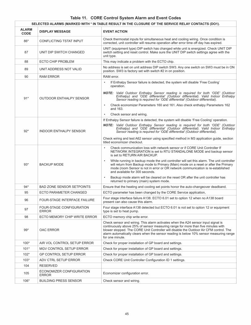
45
Table 11. CORE Control System Alarm and Event CodesSELECTED ALARMS (MARKED WITH * IN TABLE RESULT IN THE CLOSURE OF THE SERVICE RELAY CONTACTS (DO1).
ALARM CODE DISPLAY MESSAGE EVENT ACTION
86* CONFLICTING TSTAT INPUT Check thermostat inputs for simultaneous heat and cooling wiring. Once condition is corrected, unit controller will resume operation after error time off day has expired.
87 UNIT DIP SWITCH CHANGEDUNIT (equipment type) DIP switch has changed while unit is energized. Check UNIT DIP switch setting and reset control. Make sure the UNIT DIP switch settings agree with the unit type.
88 ECTO CHIP PROBLEM This may indicate a problem with the ECTO chip.
89 UNIT ADDRESS NOT VALID No address is set on unit address DIP switch SW3. Any one switch on SW3 must be in ON position. SW3 is factory set with switch #2 in on position.
90 RAM ERROR RAM error.
91* OUTDOOR ENTHALPY SENSOR
• If Enthalpy Sensor failure is detected, the system will disable ‘Free Cooling’ operation.
NOTE: Valid Outdoor Enthalpy Sensor reading is required for both ‘ODE’ (Outdoor Enthalpy) and ‘ODE differential’ (Outdoor differential). Valid Indoor Enthalpy Sensor reading is required for ‘ODE differential’ (Outdoor differential).
• Check economizer Parameters 160 and 161. Also check enthalpy Parameters 162 and 163.
• Check sensor and wiring.
92* INDOOR ENTHALPY SENSOR
If Enthalpy Sensor failure is detected, the system will disable ‘Free Cooling’ operation.NOTE: Valid Outdoor Enthalpy Sensor reading is required for both ‘ODE’ (Outdoor
Enthalpy) and ‘ODE differential’ (Outdoor differential). Valid Indoor Enthalpy Sensor reading is required for ‘ODE differential’ (Outdoor differential).
CheckwiringandtestA62sensorusingspecifiedmethodinM3applicationguide,sectiontitled economizer checkout.
93* BACKUP MODE
• Check communication loss with network sensor or if CORE Unit Controller If NETWORK INTEGRATION is set to RTU STANDALONE MODE and backup sensor is set to RETURN AIR BACKUP.
• While running in backup mode the unit controller will set this alarm. The unit controller will return from Backup mode to Primary (Main) mode on a reset or after the Primary mode (room Sensor is not in error or OR network communication is re-established and available for 300 seconds.
• Backup mode alarm will be cleared on the reset OR after the unit controller has returned to primary (main) system mode.
94* BAD ZONE SENSOR SETPOINTS Ensure that the heating and cooling set points honor the auto-changeover deadband.
95 ECTO PARAMETER CHANGED ECTO parameter has been changed by the CORE Service application,
96 FOUR-STAGE INTERFACE FAILURE Four stage interface failure A138. ECTO 6.01 set to option 12 when no A138 board present can also cause this alarm.
97 FOUR-STAGE CONFIGURATION ERROR
Four stage interface A138 detected but ECTO 6.01 is not set to option 12 or equipment type is set to heat pump.
98 ECTO MEMORY CHIP WRITE ERROR ECTO memory chip write error.
99* OAC ERROR
Check sensor and wiring. This alarm activates when the A24 sensor input signal is continuouslyabove25%ofsensormeasuringrangeformorethanfiveminuteswithblower stopped. The CORE Unit Controller will disable the Outdoor Air CFM control. The alarm automatically clears when the sensor reading is below 10% sensor measuring range for one minute.
100* AIR VOL CONTROL SETUP ERROR Check for proper installation of GP board and settings.
101* MGV CONTROL SETUP ERROR Check for proper installation of GP board and settings.
102* GP CONTROL SETUP ERROR Check for proper installation of GP board and settings.
103* ADV CTRL SETUP ERROR CheckCOREUnitControllerConfigurationID1settings.
104 RESERVED
105 ECONOMIZER CONFIGURATION ERROR Economizerconfigurationerror.
106* BUILDING PRESS SENSOR Check sensor and wiring.

46
Table 11. CORE Control System Alarm and Event CodesSELECTED ALARMS (MARKED WITH * IN TABLE RESULT IN THE CLOSURE OF THE SERVICE RELAY CONTACTS (DO1).
ALARM CODE DISPLAY MESSAGE EVENT ACTION
107* DUCT SUPPLY PRESS SENSOR
Check sensor and wiring.The unit controller will set Supply Air Static Pressure Sensor (A30) error status if:• Input signal is above 4.9” wc for more than 30 seconds.
OR• Input signal is below 0.1”wc 20 seconds after the blower has started with setting at or
above Blower Output Static Duct Alarm Check.
The CORE Unit Controller will clear the Supply Air Static Pressure Sensor (A30) error status and alarm after the expiration of Error Time OFF delay.
108 DUCT SUPPLY HIGH PRESS SENSOR
• Check sensor and wiring.
• The CORE Unit Controller will shutdown operation for Error Off time (Parameter 110) if supply air static pressure exceeds supply static shutdown setpoint for 20 seconds (default) Parameter 42.
• The CORE Unit Controller will clear High Supply Static (Duct) Pressure after Error Off Time has expired and static duct pressure is below Supply Static Set Point Shutdown.
109* STRIKE3 DUCT SUPPLY PRESS SENSOR
• Check sensor and wiring.
• Unit controller shall “lock out” a unit operation after the Max Static Duct Pressure Occurrences have occurred of Supply Static Pressure Sensor Error (alarm 107) and/or High Supply Static (Duct) Pressure (alarm 108).
• User shall be able to clear supply static pressure lockout and alarm via User Interface. Supply Static Pressure lockout and alarm shall be cleared after the unit controller reset.
• The number of strikes is three by default. this can be changed using Parameter 43. Optional occurrence setting is 1 to 7.
110 WAITING SENSOR DATA Check network or comfort sensor and wiring.
111 PROFILE ERROR Configurationprofileunrecoverable.Settingsmayhavechanged.
112 INTERNAL EEPROM ERASE ERROR Internal EEPROM erase error.
113 INTERNAL EEPROM WRITE ERROR Internal EEPROM write error.
114 INTERNAL PLL CLOCK ERROR Internal PLL clock error.
115 TEST MODE UNIT TEST switch in test mode.
116 TEST MODE AT RESET UNIT TEST switch in test mode at reset.
117 HIBERNATION MODE To insure correct voltage phasing before startup, use refrigerant pressure gauges to check proper compressor operation and arrow label for blower rotation.
118 NO DISPLAY Display is not connected or communication lost
119 RESERVED
120 MCB CONFIGURATION ERROR MCBconfigurationerror.Casesthatcancausethisalarm:1-MCBnotpresent,butECTO0.01 requires it. 2-MCB present, but ECTO 0.01 is not set for it
121* ID LINE FREQ MISMATCH
Power source line frequency is determined by the entered model number. This alarm is enabled by the Phase Voltage Detection feature. The CORE Unit Controller does not have an automatic clearing method, unit power cycle or reset will be required to re-evaluate the phase sequence again.
122* 24VAC PRIMARY VOLTAGE LOW
• Low output voltage on T1 transformer. Alarm set when 24VAC voltage low if calculated RMS voltage is below low voltage alarm threshold for more than two seconds. System will stop unit operations (cooling, heating and ventilation). Low voltage threshold is 18VAC.
• The CORE Unit Controller will clear alarm 24VAC Voltage Low if calculated RMS voltage is above Low Voltage Alarm Threshold + 1 VAC for more than two seconds. After the low 24VAC alarm has been cleared, the CORE Unit Controller will ignore all service demands until the Error Time Off Delay has expired.
123* 24VAC PRIMARY VOLTAGE HIGH
• High output voltage on T1 transformer. Alarm set when 24VAC voltage high if calculated RMS voltage is below low voltage alarm threshold for more than two seconds. System will stop unit operations (cooling, heating and ventilation). Low voltage threshold is 30VAC.
• The CORE Unit Controller will clear alarm 24VAC Voltage high if calculated RMS voltage is above High Voltage Alarm Threshold + 1 VAC for more than two seconds. After the HIGH 24VAC alarm has been cleared, the CORE Unit Controller will ignore all service demands until the Error Time Off Delay has expired.

47
Table 11. CORE Control System Alarm and Event CodesSELECTED ALARMS (MARKED WITH * IN TABLE RESULT IN THE CLOSURE OF THE SERVICE RELAY CONTACTS (DO1).
ALARM CODE DISPLAY MESSAGE EVENT ACTION
124* 24VAC SECONDARY VOLTAGE LOW
• Low output voltage on T1 transformer. alarm set when 24VAC voltage low if calculated RMS voltage is below low voltage alarm threshold for more than two seconds. System will stop unit operations (cooling, heating and ventilation). Low voltage threshold is 18VAC.
• The CORE Unit Controller will clear alarm 24VAC Voltage Low if calculated RMS voltage is above Low Voltage Alarm Threshold + 1 VAC for more than two seconds. After the low 24VAC alarm has been cleared, the CORE Unit Controller will ignore all service demands until the Error Time Off Delay has expired.
125* 24VAC SECONDARY VOLTAGE HIGH
• High output voltage on T1 transformer. alarm set when 24VAC voltage high if calculated RMS voltage is below low voltage alarm threshold for more than two seconds. System will stop unit operations (cooling, heating and ventilation). Low voltage threshold is 30VAC.
• The CORE Unit Controller will clear alarm 24VAC Voltage HIGH if calculated RMS voltage is above high voltage alarm Threshold + 1 VAC for more than two seconds. After the high 24VAC alarm has been cleared the CORE Unit Controller will ignore all service demands until the Error Time Off Delay has expired.
126* LINE PHASING MISMATCH During power up or reset of unit, Mismatch on single or 3 phase power, or reverse rotation on 3 phase detected. This alarm is enabled by the Phase Voltage Detection feature.
127 ALARM BUFFER OVERLFOW Alarmbufferoverflow.
128 24VAC SECONDARY POWER LOSS Check transformer and wire connections.
129* VFD SHUTDOWN VFD fault detected. Check belt and for blower overload. Fix source of fault and reset CORE Unit Controller.
130 VFD BYPASS ENGAGED VFD bypass mode. Mode is engaged. Blower may or may not be disengage.
131 RESERVED
132 VFD BYPASS UNCONFIG VFD bypass mode has not been selected. Unit operates as if bypass is not installed.
133 RESERVED
134 LOW SUPPLY AIRFLOW AdvancedAirflowenabledRTUindicatesairflowtargetcannotbeachieved.Checkcauseofairflowreductionsuchasdirtyfilter,changesinductwork,etc
135* NO SUPPLY AIRFLOW Blower RPM is too low as indicates by blower status. This means that the blower is not working. Repair blower and reset CORE Unit Controller.
136* OA DAMPER MECH FAULT Outdoor air damper stuck or actuator problem.
137 LOW OUTDOOR AIRFLOW Outdoorairflowistoolowsothebuildingisnotgettingthedesignedoutdoorairflowbasedon IAQ.
138 RESERVED
139 HIGH OUTDOOR AIRFLOW Ventilation CFM is too high therefore the RTU is using excessive energy.
140 CFM TARGET TOO LOW Verify the MSAV blower settings and set the CM targets below set CFM. The alarm value will be displayed on the CORE Unit Controller screen.141 CFM TARGET TOO HIGH
142 RESERVED
143* OA DAMPER ERROR Outdoor air differential pressure sensor value not in valid range. Might be tubing problem or high return duct resistance.
144 FIRMWARE UPDATE COMPLETED Systemupdatedwithnewfirmware.
145 RESERVED
146 SERVICE EVENT Service event logged.
147* DAMPER FDBK LOSS During free cooling damper is not modulating.
148* EP CONFIG ERROR Economizer should be installed and blower should be ECM type.
149* OA DIFF PRESS SENSOR ERROR Check outdoor air damper differential pressure sensor and wiring.
150* NOT ECONOMIZING WHEN OAS May be due to the damper motor being unplugged or disconnected.
151* ECONOMIZING WHEN OANS This may be due to damper motor being blocked or stuck open and therefore not closing.
152 - 162 RESERVED
163 LIQUID PRESS OPEN
164 STRIKE3 LIQUID PRESS OPEN
165 ECN UNCONFIGURED ConfigurationID1,position2issettoU.Selectapplicableoptionusingsetup/installwizard.
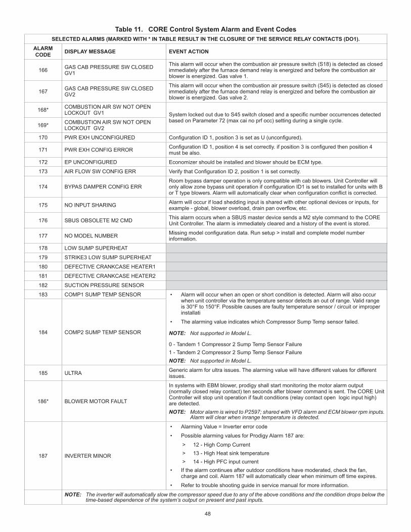
48
Table 11. CORE Control System Alarm and Event CodesSELECTED ALARMS (MARKED WITH * IN TABLE RESULT IN THE CLOSURE OF THE SERVICE RELAY CONTACTS (DO1).
ALARM CODE DISPLAY MESSAGE EVENT ACTION
166 GAS CAB PRESSURE SW CLOSED GV1
This alarm will occur when the combustion air pressure switch (S18) is detected as closed immediately after the furnace demand relay is energized and before the combustion air blower is energized. Gas valve 1.
167 GAS CAB PRESSURE SW CLOSED GV2
This alarm will occur when the combustion air pressure switch (S45) is detected as closed immediately after the furnace demand relay is energized and before the combustion air blower is energized. Gas valve 2.
168* COMBUSTION AIR SW NOT OPEN LOCKOUT GV1 SystemlockedoutduetoS45switchclosedandaspecificnumberoccurrencesdetected
based on Parameter 72 (max cai no prf occ) setting during a single cycle.169* COMBUSTION AIR SW NOT OPEN
LOCKOUT GV2
170 PWR EXH UNCONFIGURED ConfigurationID1,position3issetasU(unconfigured).
171 PWR EXH CONFIG ERROR ConfigurationID1,position4issetcorrectly.ifposition3isconfiguredthenposition4must be also.
172 EP UNCONFIGURED Economizer should be installed and blower should be ECM type.
173 AIR FLOW SW CONFIG ERR VerifythatConfigurationID2,position1issetcorrectly.
174 BYPAS DAMPER CONFIG ERR Room bypass damper operation is only compatible with cab blowers. Unit Controller will onlyallowzonebypassunitoperationifconfigurationID1issettoinstalledforunitswithBorTtypeblowers.Alarmwillautomaticallyclearwhenconfigurationconflictiscorrected.
175 NO INPUT SHARING Alarm will occur if load shedding input is shared with other optional devices or inputs, for example-global,bloweroverload,drainpanoverflow,etc.
176 SBUS OBSOLETE M2 CMD This alarm occurs when a SBUS master device sends a M2 style command to the CORE Unit Controller. The alarm is immediately cleared and a history of the event is stored.
177 NO MODEL NUMBER Missingmodelconfigurationdata.Runsetup>installandcompletemodelnumberinformation.
178 LOW SUMP SUPERHEAT
179 STRIKE3 LOW SUMP SUPERHEAT
180 DEFECTIVE CRANKCASE HEATER1
181 DEFECTIVE CRANKCASE HEATER2
182 SUCTION PRESSURE SENSOR
183 COMP1 SUMP TEMP SENSOR • Alarm will occur when an open or short condition is detected. Alarm will also occur when unit controller via the temperature sensor detects an out of range. Valid range is 30°F to 150°F. Possible causes are faulty temperature sensor / circuit or improper installati
• The alarming value indicates which Compressor Sump Temp sensor failed.
NOTE: Not supported in Model L.
0 - Tandem 1 Compressor 2 Sump Temp Sensor Failure1 - Tandem 2 Compressor 2 Sump Temp Sensor FailureNOTE: Not supported in Model L.
184 COMP2 SUMP TEMP SENSOR
185 ULTRA Generic alarm for ultra issues. The alarming value will have different values for different issues.
186* BLOWER MOTOR FAULT
In systems with EBM blower, prodigy shall start monitoring the motor alarm output (normally closed relay contact) ten seconds after blower command is sent. The CORE Unit Controller will stop unit operation if fault conditions (relay contact open logic input high) are detected.NOTE: Motor alarm is wired to P259 7; shared with VFD alarm and ECM blower rpm inputs.
Alarm will clear when in range temperature is detected.
187 INVERTER MINOR
• Alarming Value = Inverter error code
• Possible alarming values for Prodigy Alarm 187 are:
> 12 - High Comp Current > 13 - High Heat sink temperature > 14 - High PFC input current
• If the alarm continues after outdoor conditions have moderated, check the fan, charge and coil. Alarm 187 will automatically clear when minimum off time expires.
• Refer to trouble shooting guide in service manual for more information.
NOTE: The inverter will automatically slow the compressor speed due to any of the above conditions and the condition drops below the time-based dependence of the system’s output on present and past inputs.
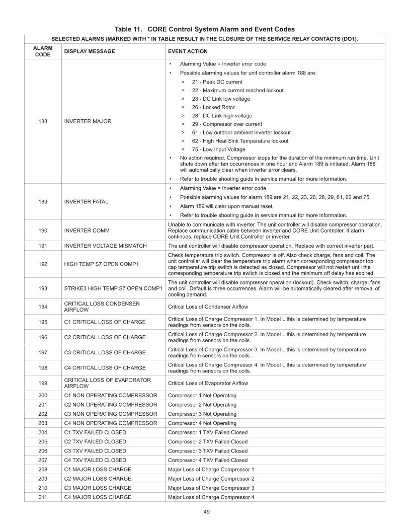
49
Table 11. CORE Control System Alarm and Event CodesSELECTED ALARMS (MARKED WITH * IN TABLE RESULT IN THE CLOSURE OF THE SERVICE RELAY CONTACTS (DO1).
ALARM CODE DISPLAY MESSAGE EVENT ACTION
188 INVERTER MAJOR
• Alarming Value = Inverter error code
• Possible alarming values for unit controller alarm 188 are:
> 21 - Peak DC current > 22 - Maximum current reached lockout > 23 - DC Link low voltage > 26 - Locked Rotor > 28 - DC Link high voltage > 29 - Compressor over current > 61 - Low outdoor ambient inverter lockout > 62 - High Heat Sink Temperature lockout > 75 - Low Input Voltage
• No action required. Compressor stops for the duration of the minimum run time. Unit shuts down after ten occurrences in one hour and Alarm 189 is initiated. Alarm 188 will automatically clear when inverter error clears.
• Refer to trouble shooting guide in service manual for more information.
189 INVERTER FATAL
• Alarming Value = Inverter error code
• Possible alarming values for alarm 189 are 21, 22, 23, 26, 28, 29, 61, 62 and 75.
• Alarm 189 will clear upon manual reset.
• Refer to trouble shooting guide in service manual for more information.
190 INVERTER COMMUnable to communicate with inverter. The unit controller will disable compressor operation. Replace communication cable between inverter and CORE Unit Controller. If alarm continues, replace CORE Unit Controller or inverter.
191 INVERTER VOLTAGE MISMATCH The unit controller will disable compressor operation. Replace with correct inverter part.
192 HIGH TEMP S7 OPEN COMP1
Check temperature trip switch. Compressor is off. Also check charge, fans and coil. The unit controller will clear the temperature trip alarm when corresponding compressor top cap temperature trip switch is detected as closed. Compressor will not restart until the corresponding temperature trip switch is closed and the minimum off delay has expired.
193 STRIKE3 HIGH TEMP S7 OPEN COMP1The unit controller will disable compressor operation (lockout). Check switch, charge, fans and coil. Default is three occurrences. Alarm will be automatically cleared after removal of cooling demand.
194 CRITICAL LOSS CONDENSER AIRFLOW CriticalLossofCondenserAirflow
195 C1 CRITICAL LOSS OF CHARGE Critical Loss of Charge Compressor 1. In Model L this is determined by temperature readings from sensors on the coils.
196 C2 CRITICAL LOSS OF CHARGE Critical Loss of Charge Compressor 2. In Model L this is determined by temperature readings from sensors on the coils.
197 C3 CRITICAL LOSS OF CHARGE Critical Loss of Charge Compressor 3. In Model L this is determined by temperature readings from sensors on the coils.
198 C4 CRITICAL LOSS OF CHARGE Critical Loss of Charge Compressor 4. In Model L this is determined by temperature readings from sensors on the coils.
199 CRITICAL LOSS OF EVAPORATOR AIRFLOW CriticalLossofEvaporatorAirflow
200 C1 NON OPERATING COMPRESSOR Compressor 1 Not Operating
201 C2 NON OPERATING COMPRESSOR Compressor 2 Not Operating
202 C3 NON OPERATING COMPRESSOR Compressor 3 Not Operating
203 C4 NON OPERATING COMPRESSOR Compressor 4 Not Operating
204 C1 TXV FAILED CLOSED Compressor 1 TXV Failed Closed
205 C2 TXV FAILED CLOSED Compressor 2 TXV Failed Closed
206 C3 TXV FAILED CLOSED Compressor 3 TXV Failed Closed
207 C4 TXV FAILED CLOSED Compressor 4 TXV Failed Closed
208 C1 MAJOR LOSS CHARGE Major Loss of Charge Compressor 1
209 C2 MAJOR LOSS CHARGE Major Loss of Charge Compressor 2
210 C3 MAJOR LOSS CHARGE Major Loss of Charge Compressor 3
211 C4 MAJOR LOSS CHARGE Major Loss of Charge Compressor 4
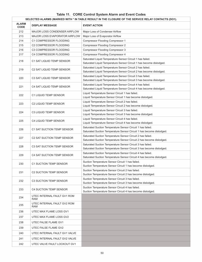
50
Table 11. CORE Control System Alarm and Event CodesSELECTED ALARMS (MARKED WITH * IN TABLE RESULT IN THE CLOSURE OF THE SERVICE RELAY CONTACTS (DO1).
ALARM CODE DISPLAY MESSAGE EVENT ACTION
212 MAJOR LOSS CONDENSER AIRFLOW MajorLossofCondenserAirflow
213 MAJOR LOSS EVAPORATOR AIRFLOW MajorLossofEvaporatorAirflow
214 C1 COMPRESSOR FLOODING Compressor Flooding Compressor 1
215 C2 COMPRESSOR FLOODING Compressor Flooding Compressor 2
216 C3 COMPRESSOR FLOODING Compressor Flooding Compressor 3
217 C4 COMPRESSOR FLOODING Compressor Flooding Compressor 4
218 C1 SAT LIQUID TEMP SENSORSaturated Liquid Temperature Sensor Circuit 1 has failed.Saturated Liquid Temperature Sensor Circuit 1 has become dislodged.
219 C2 SAT LIQUID TEMP SENSORSaturated Liquid Temperature Sensor Circuit 2 has failed.Saturated Liquid Temperature Sensor Circuit 2 has become dislodged.
220 C3 SAT LIQUID TEMP SENSORSaturated Liquid Temperature Sensor Circuit 3 has failed.Saturated Liquid Temperature Sensor Circuit 3 has become dislodged.
221 C4 SAT LIQUID TEMP SENSORSaturated Liquid Temperature Sensor Circuit 4 has failed.Saturated Liquid Temperature Sensor Circuit 4 has become dislodged.
222 C1 LIQUID TEMP SENSORLiquid Temperature Sensor Circuit 1 has failed.Liquid Temperature Sensor Circuit 1 has become dislodged.
223 C2 LIQUID TEMP SENSORLiquid Temperature Sensor Circuit 2 has failed.Liquid Temperature Sensor Circuit 2 has become dislodged.
224 C3 LIQUID TEMP SENSORLiquid Temperature Sensor Circuit 3 has failed.Liquid Temperature Sensor Circuit 3 has become dislodged.
225 C4 LIQUID TEMP SENSORLiquid Temperature Sensor Circuit 4 has failed.Liquid Temperature Sensor Circuit 4 has become dislodged.
226 C1 SAT SUCTION TEMP SENSORSaturated Suction Temperature Sensor Circuit 1 has failed.Saturated Suction Temperature Sensor Circuit 1 has become dislodged.
227 C2 SAT SUCTION TEMP SENSORSaturated Suction Temperature Sensor Circuit 2 has failed.Saturated Suction Temperature Sensor Circuit 2 has become dislodged.
228 C3 SAT SUCTION TEMP SENSORSaturated Suction Temperature Sensor Circuit 3 has failed.Saturated Suction Temperature Sensor Circuit 3 has become dislodged.
229 C4 SAT SUCTION TEMP SENSORSaturated Suction Temperature Sensor Circuit 4 has failed.Saturated Suction Temperature Sensor Circuit 4 has become dislodged.
230 C1 SUCTION TEMP SENSOR Suction Temperature Sensor Circuit 1 has failed.Suction Temperature Sensor Circuit 1 has become dislodged.
231 C2 SUCTION TEMP SENSOR Suction Temperature Sensor Circuit 2 has failed.Suction Temperature Sensor Circuit 2 has become dislodged.
232 C3 SUCTION TEMP SENSOR Suction Temperature Sensor Circuit 3 has failed.Suction Temperature Sensor Circuit 3 has become dislodged.
233 C4 SUCTION TEMP SENSOR Suction Temperature Sensor Circuit 4 has failed.Suction Temperature Sensor Circuit 4 has become dislodged.
234 UTEC INTERNAL FAULT GV1 ROM RAM
235 UTEC INTERNAL FAULT GV2 ROM RAM
236 UTEC MAX FLAME LOSS GV1
237 UTEC MAX FLAME LOSS GV2
238 UTEC FALSE FLAME GV1
239 UTEC FALSE FLAME GV2
240 UTEC INTERNAL FAULT GV1 VALVE
241 UTEC INTERNAL FAULT GV2 VALVE
242 UTEC VALVE FAULT LOCKOUT GV1

51
Table 11. CORE Control System Alarm and Event CodesSELECTED ALARMS (MARKED WITH * IN TABLE RESULT IN THE CLOSURE OF THE SERVICE RELAY CONTACTS (DO1).
ALARM CODE DISPLAY MESSAGE EVENT ACTION
243 UTEC VALVE FAULT LOCKOUT GV2
244 - 255 RESERVED
500 Error Reading USB Device Error Reading USB Device
501 USB Device not Mounted USB Device not Mounted
502 USB Device Full USB Device Full
503 Invalid DIN number Invalid DIN number received from M4. Indicates DIN incompatibility

52
15. CORE Control System Unit ParametersTable 12. CORE Control System Unit Parameters
Control Parameter
NoScreen Name Parameter Short
Description
Control ValueUnits Description
Min. Default Max.
2 LANGUAGE LANGUAGEENGLISH,
SPANISH OR FRENCH
OptionSelect desired language for user interface. Options are English, French and Spanish.
Power and Damper Parameters
5 VAV CONTROL MODE
Variable Air Volume Control Mode
0 If applicable to specificunit, 511 Option
ApplicabletoStandardEfficiency3-to6-ton units only.• 16 = Runs the blower in high speed
when occupied and there is not other active demand (room sensor mode only)
• 32 = Runs the blower in high speed when G is active and there is no other active demand (thermostat mode only)
6 BLOWER SMOKE OUTPUT
Blower Smoke Output 20 Depends on
equipment 100 %
• ApplicabletoHighEfficiency3-to5-ton units.
• Blower staged percentage output during smoke detection.
7 BLOWER HEAT OUTPUT
Blower Heat Output 20 Depends on
equipment 100 %
• ApplicabletoHighEfficiency3-to5-ton units only.
• Blower staged percentage output high speed; used for high heating speed.
8 BLOWER LO CL OUTPUT
Blower Cool Output 20 Depends on
equipment 100 %
• ApplicabletoHighEfficiency3-to5-ton units only.
• Blower staged percentage output low speed; used for low cooling or ventilation.
9 MIN DAMPER LOW BLWR
Minimum Damper Position During High Speed Blower Operation
0 0 100 %
• Minimum damper position during low speed blower operation.
• Use Parameter 132 during high speed blower operation
10 FREE CL STG UP DLY
Free Cooling Blower Stage Up Delay
0 300 1800 Sec
• ApplicabletoStandardEfficiency3-to 6-ton only.
• Free cooling blower stage-up delay. Blower runs low speed during delay, and then shifts to high speed.
11 ENBL FIELD STAT RPT
Enabled Field Status Report
0 = OFF1 = ON
Option Enabled Field Status Report
12 MSAV SMK CFM
Multi-Stage Air Volume Smoke Detection Mode (Alarm)
450Default may be altered at factory test.
14400 CFM
Multi-Stage Air Volume Smoke Detection Mode (Alarm)NOTE: In order for the SMOKE CFM
change to take affect, go the SETUP > TEST & BALANCE > BLOWER and run the wizard. Performing this task will recalculate the output to the desired CFM. No adjustments are required during this procedure.
19 MAX CFM RPM
Maximum Cubic Feet Per Minute Revolutions Per Minute
445Default may be altered at factory test.
1780 RPM Maximum Cubic Feet Per Minute Revolutions Per Minute
27 MIN OUPT CL VT SMK
Minimum Output Cooling Vent Smoke Detection Mode (Alarm)
30 50 100 % Minimum Output Cooling Vent Smoke Detection Mode (Alarm)
28 MIN OUTPUT HEAT
Minimum Output Heat 30 50 100 % Minimum Output Heat
29 MIN DAMPER BLOWER
Minimum Damper Blower 0
Default may be altered at factory test.
101 % Setting this Parameter to 101.0% will disable this feature.

53
Table 12. CORE Control System Unit ParametersControl
Parameter No
Screen Name Parameter Short Description
Control ValueUnits Description
Min. Default Max.
30 PWREXH STG2 MIN BLR
Power Exhaust Stage 2 Minimum Blower
0 70 100 % Power Exhaust Stage 2 Minimum Blower
31 SUPPLY PID P CONST
Supply Proportional Base Control Loop for Variable Air Volume or Constant Air Volume with Bypass Damper
0 17 127 CountsVariable Air Volume or Constant Air Volume with Bypass Damper supply PID Proportional constant.
32 SUPPLY PID I CONST
Supply Integral Base Control Loop for Variable Air Volume or Constant Air Volume with Bypass Damper
0 12 127 CountsVariable Air Volume or Constant Air Volume with Bypass Damper supply PID Integral constant.
33 SUPPLY PID D CONST
Supply Derivative Base Control Loop for Variable Air Volume or Constant Air Volume with Bypass Damper
0 0 127 CountsVariable Air Volume or Constant Air Volume with Bypass Damper supply PID derivative constant.
34 BLR STC PRESS SMK SP
Constant Air Volume with Bypass Damper Static Pressure Set Point During Smoke Alarm
0 1 5 w.c.Constant air volume with bypass damper static pressure set point during smoke alarm.
35 BLR STC PRES VT SP
Constant Air Volume with Bypass Damper Static Pressure Set Point for Ventilation
0 1 5 w.c. Constant air volume with bypass damper static pressure set point for ventilation.
36 BLR STC PRES HT SP
Constant Air Volume with Bypass Damper Static Pressure Set Point for Heating
0 1 5 w.c. Constant air volume with bypass damper static pressure set point for heating
37 BLR STC PRES CL SP
Constant Air Volume with Bypass Damper Static Pressure Set Point for Cooling
0 1 5 w.c. Constant air volume with bypass damper static pressure set point for cooling
38 MIN OUTPT CL VT SMK
Constant Air Volume with Bypass Damper Minimum Output Percentage Set Point for Cooling, Ventilation and Smoke Alarms
20 20 100 %
• Constant air volume with bypass damper minimum output for cooling, ventilation and during smoke alarms. This sets the minimum air delivered.
• Bypass damper motor is set to 10 to 2 volts with 10 volts being closed.
• 20% setting = 2 volts or damper completely opened.
39 MIN OUTPUT HEAT
Constant Air Volume with Bypass Damper Minimum Output Percentage Set Point for Heating
20 20 100 %
• Constant air volume with bypass damper minimum output for heating.
• This sets the minimum air delivered.
• Bypass damper motor is set to 10 to 2 volts with 10 volts being closed.
• 20% setting = 2 volts or damper completely opened.

54
Table 12. CORE Control System Unit ParametersControl
Parameter No
Screen Name Parameter Short Description
Control ValueUnits Description
Min. Default Max.
40 BLOWER MAX OUTPUT
Constant Air Volume with Bypass Damper Maximum Output Percentage Set Point
40 100 100 %
• Constant air volume with bypass damper maximum output.
• This sets the maximum air delivered.
• Bypass damper motor is set to 10 to 2 volts with 10 volts being closed.
• 100% setting = 10 volts or damper completely closed.
41 SUPPLY MANUAL RESET
Constant Air Volume with Bypass Damper Manual Reset Value Output Percentage Set Point
20 52 100 %Constant air volume with bypass damper manual reset value output. This is the output when unit is off.
42 STATIC SHUTDOWN SP
Air Supply Static Shutdown Set Point
0 2 5 w.c.
Supply static shutdown set point. Unit will shutdown for Parameter 110 minutes if duct pressure exceeds this value for 20 seconds.
43 STATIC LOCKOUT CNT
Static Pressure Lockout Counter Set Point
1 3 7 Counts
• The number of occurrences before permanent lockout. Counter resets when unit controller resets.
• Refer to Parameter 226 to either enable or disable this feature.
44 STATIC LO ALARM CHK
Supply Static Sensor (A30) Low Alarm Percentage Set Point
30 40 100 %
• Supply Static Pressure Sensor (A30) connected at (A133_P195_6) (TB18_6) alarm threshold.
• Blower percent speed before checking sensor after a 20 second delay.
• A value of 30% disables the low threshold or “open” alarm trap.
Electric Heating Parameters
58 HT ELEC WARMUP DLAY
Electric Heat Warm-up Time Delay for Economizer
0 60 136 MinutesWarm-up time delay. The time that the economizer is forced closed during warm-up(firstoccupied+heatdemand)
60 HT ELEC BL OFF DLAY
Electric Heat Blower Off Delay Set Point.
0 System Dependent 300 Seconds The time the blower stays on after the
heatingdemandissatisfied.
61 HT ELEC MAX LT OCC
Electric Heat Maximum Primary and Secondary
1 3 15 Counts
Service output activation. Maximum Primary and Secondary Limit occurrences stored before service relay is energized.NOTE: Heating stage is not locked out.
62 HT ELEC STAGE DELAY
Electric Heat Time Delay Between Heat Stages
12 12 60 Seconds Time delay between heat stages.
63 HT ELEC STG UP TMR
Electric Heat Maximum Lower Stage Run Time in Room Sensor Applications
0 912 3600 Seconds
• Stage up timer. The maximum time that lower stage runs before calling next heat stage. Used in room sensor applications.
• Disabled if set to 0.
64 HT ELEC STG DWN TMR
Electric Heat Time Delay for Lower Stage Termination Following Higher Stage Termination
0 0 3600 Seconds
• Time delay before a lower stage turns off following a higher stage termination.
• Used in room sensor applications.
Gas Heating Parameters
65 HT GAS WARMUP DELAY
Gas Time Delay for Economizer Being Closed During Warm-up
0 60 136 MinutesWarm-up time delay. The time that the economizer is forced closed during warm-up(firstoccupied+heatdemand).
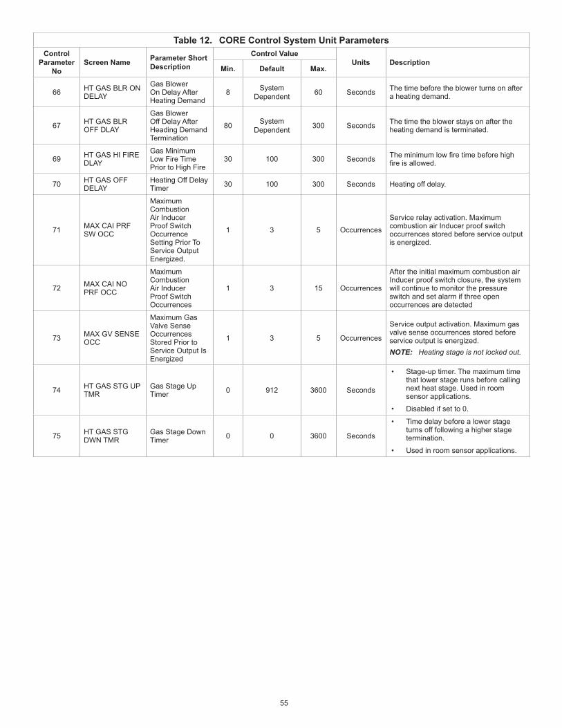
55
Table 12. CORE Control System Unit ParametersControl
Parameter No
Screen Name Parameter Short Description
Control ValueUnits Description
Min. Default Max.
66 HT GAS BLR ON DELAY
Gas Blower On Delay After Heating Demand
8 System Dependent 60 Seconds The time before the blower turns on after
a heating demand.
67 HT GAS BLR OFF DLAY
Gas Blower Off Delay After Heading Demand Termination
80 System Dependent 300 Seconds The time the blower stays on after the
heating demand is terminated.
69 HT GAS HI FIRE DLAY
Gas Minimum Low Fire Time Prior to High Fire
30 100 300 Seconds Theminimumlowfiretimebeforehighfireisallowed.
70 HT GAS OFF DELAY
Heating Off Delay Timer 30 100 300 Seconds Heating off delay.
71 MAX CAI PRF SW OCC
Maximum Combustion Air Inducer Proof Switch Occurrence Setting Prior To Service Output Energized.
1 3 5 Occurrences
Service relay activation. Maximum combustion air Inducer proof switch occurrences stored before service output is energized.
72 MAX CAI NO PRF OCC
Maximum Combustion Air Inducer Proof Switch Occurrences
1 3 15 Occurrences
After the initial maximum combustion air Inducer proof switch closure, the system will continue to monitor the pressure switch and set alarm if three open occurrences are detected
73 MAX GV SENSE OCC
Maximum Gas Valve Sense Occurrences Stored Prior to Service Output Is Energized
1 3 5 Occurrences
Service output activation. Maximum gas valve sense occurrences stored before service output is energized.NOTE: Heating stage is not locked out.
74 HT GAS STG UP TMR
Gas Stage Up Timer 0 912 3600 Seconds
• Stage-up timer. The maximum time that lower stage runs before calling next heat stage. Used in room sensor applications.
• Disabled if set to 0.
75 HT GAS STG DWN TMR
Gas Stage Down Timer 0 0 3600 Seconds
• Time delay before a lower stage turns off following a higher stage termination.
• Used in room sensor applications.
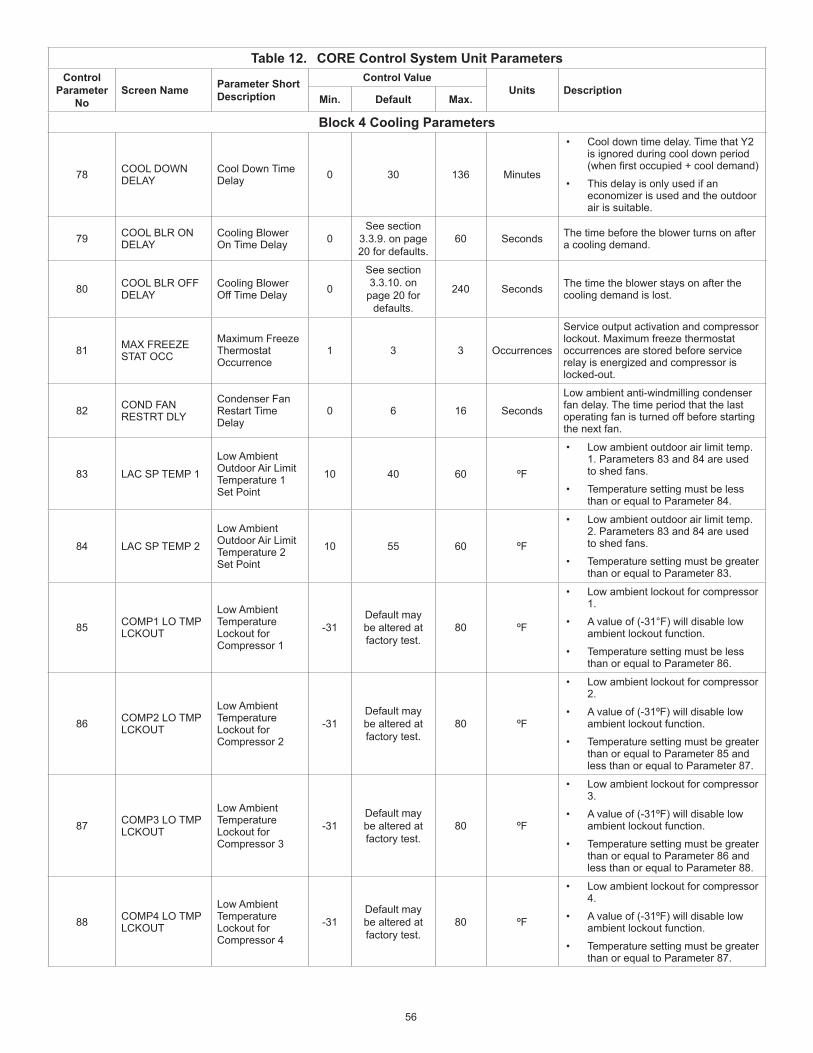
56
Table 12. CORE Control System Unit ParametersControl
Parameter No
Screen Name Parameter Short Description
Control ValueUnits Description
Min. Default Max.
Block 4 Cooling Parameters
78 COOL DOWN DELAY
Cool Down Time Delay 0 30 136 Minutes
• Cool down time delay. Time that Y2 is ignored during cool down period (whenfirstoccupied+cooldemand)
• This delay is only used if an economizer is used and the outdoor air is suitable.
79 COOL BLR ON DELAY
Cooling Blower On Time Delay 0
See section 3.3.9. on page 20 for defaults.
60 Seconds The time before the blower turns on after a cooling demand.
80 COOL BLR OFF DELAY
Cooling Blower Off Time Delay 0
See section 3.3.10. on
page 20 for defaults.
240 Seconds The time the blower stays on after the cooling demand is lost.
81 MAX FREEZE STAT OCC
Maximum Freeze Thermostat Occurrence
1 3 3 Occurrences
Service output activation and compressor lockout. Maximum freeze thermostat occurrences are stored before service relay is energized and compressor is locked-out.
82 COND FAN RESTRT DLY
Condenser Fan Restart Time Delay
0 6 16 Seconds
Low ambient anti-windmilling condenser fan delay. The time period that the last operating fan is turned off before starting the next fan.
83 LAC SP TEMP 1
Low Ambient Outdoor Air Limit Temperature 1 Set Point
10 40 60 ºF
• Low ambient outdoor air limit temp. 1. Parameters 83 and 84 are used to shed fans.
• Temperature setting must be less than or equal to Parameter 84.
84 LAC SP TEMP 2
Low Ambient Outdoor Air Limit Temperature 2 Set Point
10 55 60 ºF
• Low ambient outdoor air limit temp. 2. Parameters 83 and 84 are used to shed fans.
• Temperature setting must be greater than or equal to Parameter 83.
85 COMP1 LO TMP LCKOUT
Low Ambient Temperature Lockout for Compressor 1
-31Default may be altered at factory test.
80 ºF
• Low ambient lockout for compressor 1.
• A value of (-31°F) will disable low ambient lockout function.
• Temperature setting must be less than or equal to Parameter 86.
86 COMP2 LO TMP LCKOUT
Low Ambient Temperature Lockout for Compressor 2
-31Default may be altered at factory test.
80 ºF
• Low ambient lockout for compressor 2.
• A value of (-31ºF) will disable low ambient lockout function.
• Temperature setting must be greater than or equal to Parameter 85 and less than or equal to Parameter 87.
87 COMP3 LO TMP LCKOUT
Low Ambient Temperature Lockout for Compressor 3
-31Default may be altered at factory test.
80 ºF
• Low ambient lockout for compressor 3.
• A value of (-31ºF) will disable low ambient lockout function.
• Temperature setting must be greater than or equal to Parameter 86 and less than or equal to Parameter 88.
88 COMP4 LO TMP LCKOUT
Low Ambient Temperature Lockout for Compressor 4
-31Default may be altered at factory test.
80 ºF
• Low ambient lockout for compressor 4.
• A value of (-31ºF) will disable low ambient lockout function.
• Temperature setting must be greater than or equal to Parameter 87.

57
Table 12. CORE Control System Unit ParametersControl
Parameter No
Screen Name Parameter Short Description
Control ValueUnits Description
Min. Default Max.
89 COMP MIN OFF DELAY
Compressor Minimum Off Delay
60 300 510 Seconds Compressor minimum off delay.
91 COMP MIN RUN TIME
Compressor Minimum Run Time
60 240 510 Seconds Compressor minimum run time.
98 MAX HP OCCURRENCES
Maximum High Pressure Occurrences
1 3 7 Occurrences
Maximum High Pressure occurrences that are stored before control locks off compressor stage and energizes the service output.
99 MAX LP OCCURRENCES
Maximum Low Pressure Occurrences
1 3 7 Occurrences
Maximum Low Pressure occurrences that are stored before control locks off compressor stage and energizes the service relay.
100 LP SW IGNORE TIME
Low Pressure Switch Ignore Time
0 120 600 Seconds Low Pressure Switch Ignore Time
101 CL STG 2 STGUP TIME
Maximum Stage 1 Cooling Time Before Call for Stage 2 Cooling
0 912 3600 Seconds
• Stage 2 stage up timer. The maximum time that cooling stage 1 runs before calling cooling stage 2.
• Used in room sensor applications.
• Disabled if set to 0.
102 CL STG 3 STGUP TIME
Maximum Stage 2 Cooling Time Before Call for Stage 3 Cooling
0 912 3600 Seconds
• Stage 3 stage up timer. The maximum time that cooling stage 2 runs before calling cooling stage 3.
• Used in room sensor applications.
• Disabled if set to 0.
103 CL STG 4 STGUP TIME
Maximum Stage 3 Cooling Time Before Call for Stage 4 Cooling
0 912 3600 Seconds
• Stage 4 stage up timer. The maximum time that cooling stage 3 runs before calling cooling stage 4.
• Used in room sensor applications.
• Disabled if set to 0
104 CL STAGE DOWN TIME
Cooling Stage Down Time 0 912 3600 Seconds
• Time delay before a lower stage turns off following a higher stage termination.
• Used in room sensor applications.
105 DEHUMID MODE DehumidificationMode 0
0 - No Humiditrol is
installed6 - All Others(Check Unit Parameter
Label)
7 Option
DehumidificationMode• 0 = No reheat.
• 1 = Supermarket reheat using De-Humidistat (wired thermostat mode only)
• 2 = Supermarket reheat using relative humidity sensor.
• 3 = Humiditrol reheat. Conditions: Blower must be energized, Must be occupied, At least one previous cooling demand.
• 4 = Relative Humidity measurement / display. No Supermarket or Humiditrol reheat.
• 5 = Humiditrol reheat. Conditions: At least one previous cooling demand.
• 6 = Humiditrol reheat. Conditions: Blower must be energized, Must be occupied.
• 7 = Humiditrol reheat. Conditions: None
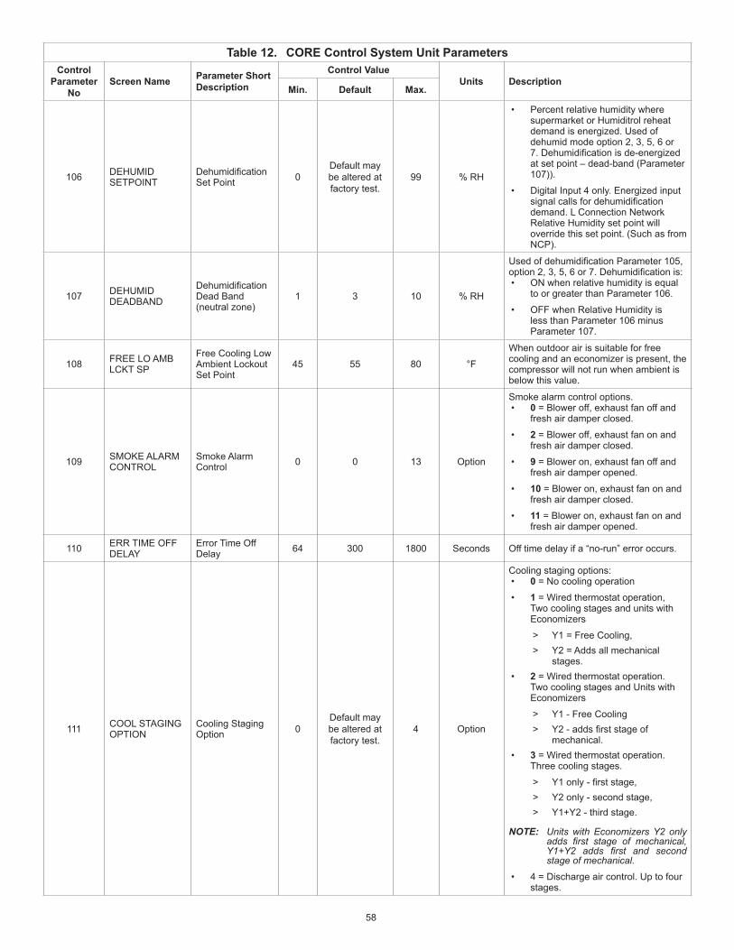
58
Table 12. CORE Control System Unit ParametersControl
Parameter No
Screen Name Parameter Short Description
Control ValueUnits Description
Min. Default Max.
106 DEHUMID SETPOINT
DehumidificationSet Point 0
Default may be altered at factory test.
99 % RH
• Percent relative humidity where supermarket or Humiditrol reheat demand is energized. Used of dehumid mode option 2, 3, 5, 6 or 7.Dehumidificationisde-energizedat set point – dead-band (Parameter 107)).
• Digital Input 4 only. Energized input signalcallsfordehumidificationdemand. L Connection Network Relative Humidity set point will override this set point. (Such as from NCP).
107 DEHUMID DEADBAND
DehumidificationDead Band (neutral zone)
1 3 10 % RH
UsedofdehumidificationParameter105,option2,3,5,6or7.Dehumidificationis:• ON when relative humidity is equal
to or greater than Parameter 106.
• OFF when Relative Humidity is less than Parameter 106 minus Parameter 107.
108 FREE LO AMB LCKT SP
Free Cooling Low Ambient Lockout Set Point
45 55 80 °F
When outdoor air is suitable for free cooling and an economizer is present, the compressor will not run when ambient is below this value.
109 SMOKE ALARM CONTROL
Smoke Alarm Control 0 0 13 Option
Smoke alarm control options.• 0 = Blower off, exhaust fan off and
fresh air damper closed.
• 2 = Blower off, exhaust fan on and fresh air damper closed.
• 9 = Blower on, exhaust fan off and fresh air damper opened.
• 10 = Blower on, exhaust fan on and fresh air damper closed.
• 11 = Blower on, exhaust fan on and fresh air damper opened.
110 ERR TIME OFF DELAY
Error Time Off Delay 64 300 1800 Seconds Off time delay if a “no-run” error occurs.
111 COOL STAGING OPTION
Cooling Staging Option 0
Default may be altered at factory test.
4 Option
Cooling staging options:• 0 = No cooling operation
• 1 = Wired thermostat operation, Two cooling stages and units with Economizers
> Y1 = Free Cooling, > Y2 = Adds all mechanical
stages.• 2 = Wired thermostat operation.
Two cooling stages and Units with Economizers
> Y1 - Free Cooling > Y2-addsfirststageof
mechanical.• 3 = Wired thermostat operation.
Three cooling stages.
> Y1only-firststage, > Y2 only - second stage, > Y1+Y2 - third stage.
NOTE: Units with Economizers Y2 only adds first stage of mechanical, Y1+Y2 adds first and second stage of mechanical.
• 4 = Discharge air control. Up to four stages.

59
Table 12. CORE Control System Unit ParametersControl
Parameter No
Screen Name Parameter Short Description
Control ValueUnits Description
Min. Default Max.
Block 5 Miscellaneous Parameters
112 HEAT STAGING OPTION
Heating Staging Option 0 2 2 Option
Heating staging options:• 0 = No heating operation.
• 1 = Discharge air control with up to four stages.
• 2 = Thermostat operation.
113 EN RET AIR TMP LMT
Enable Return Air Temperature Limit 0 0 1 Option
• Enables return air temperature limit option.
• Return air limits may be used for limiting zone temperatures. Continuous fan operation recommended.
114 COOL RET AIR LIMIT
Cooling Return Air Limit 60 65 80 °F
• Return air limit for cooling. If the return air cooling limit is exceeded, the cooling demands are interrupted.
• Parameter 113 must be set to 1 to enable.
115 HEAT RET AIR LIMIT
Heating Return Air Limit 60 85 100 °F
• Return air limit for heating. If the return air heating limit is exceeded, the heating demands are interrupted.
• Parameter 113 must be set to 1 to enable.
117 DCV MAX DAMPER OPEN
Demand Control Ventilation Maximum Damper Open
0 50 100 % Maximum allowed demand control ventilation damper open position.
118 DCV DAMP START OPEN
Demand Control Ventilation Damper Start Open
0 700 2000 PPM
• Damper “start open” CO2 set point for Demand Control Ventilation.
• Level where fresh air damper begins to open.
119 DCV DAMP FULL OPEN
Demand Control Ventilation Maximum Damper Full Open Set Point
0 1200 2000 PPM
• Damper “full open” CO2 set point for Demand Control Ventilation.
• Level where fresh air damper is opened to maximum.
120 DCV HI TMP OV FL CL
Demand Control Ventilation Outdoor Air Control Hi Temperature Override Full Closed
-31 105 132 °F High outdoor air temp. where fresh air damper is closed to minimum position.
121 DCV HI TMP OV ST CL
Demand Control Ventilation Outdoor Air Control Hi Temperature Override Start Closing
-31 75 132 °F High outdoor air temperature where fresh air damper begins to close.
122 DCV LO TMP OV FL CL
Demand Control Ventilation Outdoor Air Control Low Temperature Override Full Closed
-31 10 132 °F Low outdoor air temperature where fresh air damper is closed to minimum position
123 DCV LO TMP OV ST CL
Demand Control Ventilation Outdoor Air Control Low Temperature Override Start Closing
-31 40 132 °F Low outdoor air temp. where fresh air damper begins to close.
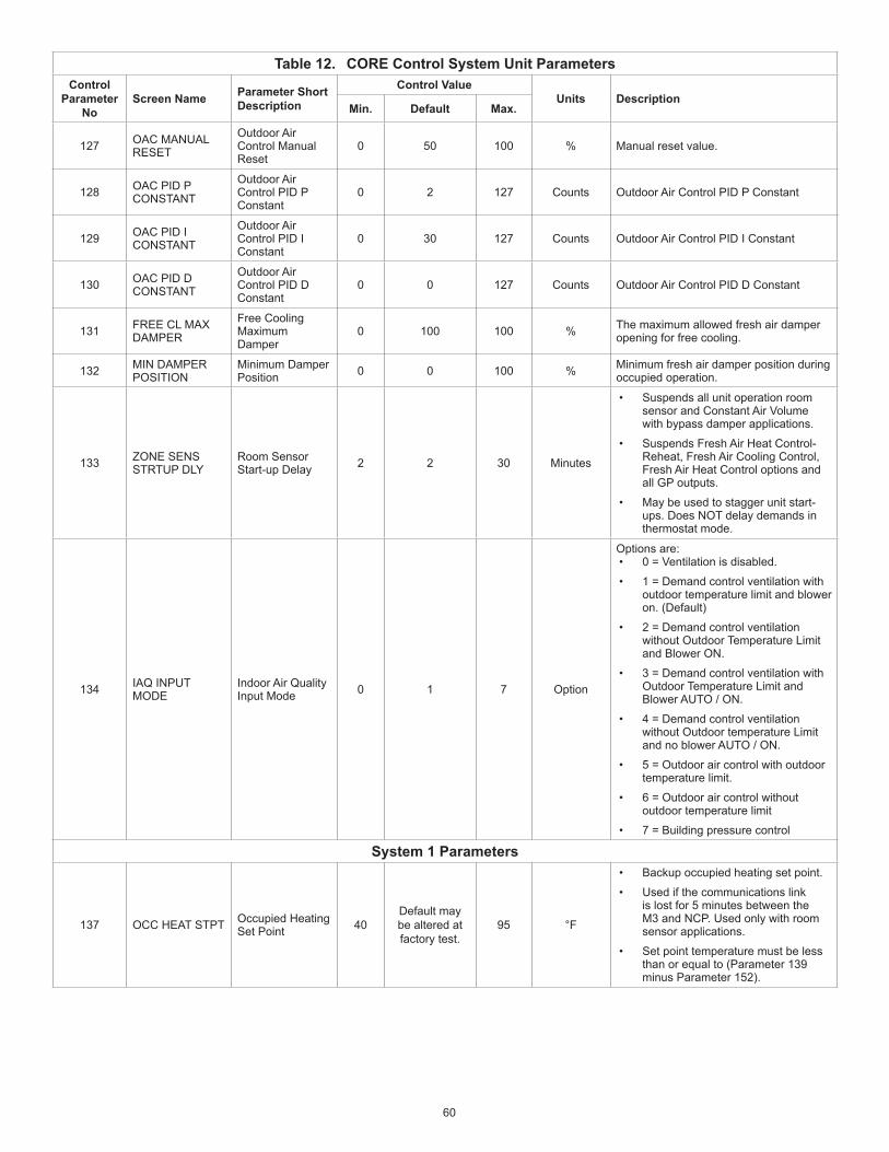
60
Table 12. CORE Control System Unit ParametersControl
Parameter No
Screen Name Parameter Short Description
Control ValueUnits Description
Min. Default Max.
127 OAC MANUAL RESET
Outdoor Air Control Manual Reset
0 50 100 % Manual reset value.
128 OAC PID P CONSTANT
Outdoor Air Control PID P Constant
0 2 127 Counts Outdoor Air Control PID P Constant
129 OAC PID I CONSTANT
Outdoor Air Control PID I Constant
0 30 127 Counts Outdoor Air Control PID I Constant
130 OAC PID D CONSTANT
Outdoor Air Control PID D Constant
0 0 127 Counts Outdoor Air Control PID D Constant
131 FREE CL MAX DAMPER
Free Cooling Maximum Damper
0 100 100 % The maximum allowed fresh air damper opening for free cooling.
132 MIN DAMPER POSITION
Minimum Damper Position 0 0 100 % Minimum fresh air damper position during
occupied operation.
133 ZONE SENS STRTUP DLY
Room Sensor Start-up Delay 2 2 30 Minutes
• Suspends all unit operation room sensor and Constant Air Volume with bypass damper applications.
• Suspends Fresh Air Heat Control-Reheat, Fresh Air Cooling Control, Fresh Air Heat Control options and all GP outputs.
• May be used to stagger unit start-ups. Does NOT delay demands in thermostat mode.
134 IAQ INPUT MODE
Indoor Air Quality Input Mode 0 1 7 Option
Options are:• 0 = Ventilation is disabled.
• 1 = Demand control ventilation with outdoor temperature limit and blower on. (Default)
• 2 = Demand control ventilation without Outdoor Temperature Limit and Blower ON.
• 3 = Demand control ventilation with Outdoor Temperature Limit and Blower AUTO / ON.
• 4 = Demand control ventilation without Outdoor temperature Limit and no blower AUTO / ON.
• 5 = Outdoor air control with outdoor temperature limit.
• 6 = Outdoor air control without outdoor temperature limit
• 7 = Building pressure control
System 1 Parameters
137 OCC HEAT STPT Occupied Heating Set Point 40
Default may be altered at factory test.
95 °F
• Backup occupied heating set point.
• Used if the communications link is lost for 5 minutes between the M3 and NCP. Used only with room sensor applications.
• Set point temperature must be less than or equal to (Parameter 139 minus Parameter 152).

61
Table 12. CORE Control System Unit ParametersControl
Parameter No
Screen Name Parameter Short Description
Control ValueUnits Description
Min. Default Max.
138 UNOCC HEAT STPT
Unoccupied Heating Set Point 40 60 95 °F
• Backup unoccupied heating set point. Used if the communications link is lost for 5 minutes between the unit controller and NCP.
• Used only in room sensor applications.
• Set point temperature must be less than or equal to (Parameter 140 minus Parameter 152).
139 OCC COOL STPT
Occupied Cooling Set Point 40 75 95 °F
• Backup occupied cooling set point.
• Used if the communications link is lost for 5 minutes between the unit controller and NCP. Used only in room sensor applications.
• Set point temperature must be greater than or equal to Parameter 137 plus Parameter 152).
140 UNOCC COOL STPT
Unoccupied Cooling Set Point 40 85 95 °F
• Backup unoccupied cooling set point.
• Used if the communications link is lost for 5 minutes between the CORE Unit Controller and network control panel. Used only in room sensor applications.
• Set point temperature must be greater than or equal to Parameter 138 plus Parameter 152).
141 AFTERHOUR OVRRD DLY
After Hours Override Time Delay
0 60 480 Minutes
• After hours override timer.
• Only used on room sensor applications without a network control panel.
142 HEAT STAGE DEADBAND
Heat Stage Deadband 1 1 3.75 °F
• Heating dead-band. Used only with CORE Unit Controller room sensor applications.
• Dead band must be less than or equal to Parameter 152 minus Parameter 143.
143 COOL STAGE DEADBAND
Cool Stage Deadband 1 1 3.75 °F
• Cooling dead-band. Used only with room sensor applications.
• Dead band must be less than or equal to Parameter 152 minus Parameter 142.
144 COOL STAGE1 DIFFER
Cooling Stage 1 Differential 0 0.5 3 °F
• Cooling stage 1 differential. Used only with room sensor applications.
• Differential temperature must be less than or equal to Parameter 145.
145 COOL STAGE2 DIFFER
Cooling Stage 2 Differential 0 1 3 °F
• Cooling stage 2 differential. Used only with room sensor applications.
• Differential temperature must be greater than or equal to Parameter 144 and less than or equal to Parameter 146.
146 COOL STAGE3 DIFFER
Cooling Stage 3 Differential 0 1.5 3 °F
• Cooling stage 3 differential. Used only with room sensor applications.
• Differential temperature must be greater than or equal to Parameter 145 and less than or equal to Parameter 147.

62
Table 12. CORE Control System Unit ParametersControl
Parameter No
Screen Name Parameter Short Description
Control ValueUnits Description
Min. Default Max.
147 COOL STAGE4 DIFFER
Cooling Stage 4 Differential 0 2 3 °F
• Cooling stage 4 differential. Used only with room sensor applications.
• Differential temperature must be greater than or equal to Parameter 146.
148 HEAT STAGE1 DIFFER
Heating Stage 1 Differential 0 0.5 3 °F
• Heating stage 1 differential. Used only with room sensor applications.
• Differential temperature must be less than or equal to Parameter 149.
149 HEAT STAGE2 DIFFER
Heating Stage 2 Differential 0 1 3 °F
• Heating stage 2 differential. Used only with room sensor applications.
• Differential temperature must be greater or equal to Parameter 148.
150 HEAT STAGE3 DIFFER
Heating Stage 3 Differential 0 1.5 3 °F
• Heating stage 3 differential temperature. Used only with room sensor applications.
• Differential temperature must be greater than or equal to Parameter 149.
151 HEAT STAGE4 DIFFER
Heating Stage 4 Differential 0 2 3 °F
• Heating stage 4 differential temperature. Used only with room sensor applications.
• Differential temperature must greater than or equal to Parameter 150.
152 AUTO CHGOVR DEADBND
Automatic Changeover Deadband
2 3 10 °F
• Minimum auto changeover dead-band temperature. Dead band must be greater than or equal to Parameter 142 plus Parameter 143.
• Used in room sensor applications.
153 AUTO CHGOVR DELAY
Automatic Changeover Delay
1Default may be altered at factory test.
15 Minutes Auto changeover time delay. Delay between heating and cooling modes.
154 OCC BLOWER MODE
Occupied Blower Mode
AUTO-CYCLES Option
Blower control option for room sensor applications during occupied periods.• Auto Cycle: Blower cycles with
demand
• On-Continuous 1: blower is on with either the occupancy sensor or occupancy schedule indicates occupied.
• On-Continuous 2: Blower is on only when both the occupancy sensor and occupancy scheduler indicates occupied.
• On-Continuous 3: lower is on only when both the occupancy sensor and occupancy scheduler indicates occupied. in addition, blower will be on a minimum of 25% of the time when occupancy scheduler indicates occupied by the occupancy sensor indicates not occupied. The 25% minimum is achieved by turning blower on for 30 minutes and off for 90 minutes.
155 FREECOOL LOCKOUT SP
Free Cooling Lockout Set Point 30 30 60 °F
• Locks out free cooling when outdoor temperature is below the set value.
• Setting value to 29°F disables free cooling lockout.
156 FRESH AIR HEAT SP
See CORE System Application Guide for further details and to change the fresh air heat (FAH) set point. Modify the set point only using the method described in the reference section.
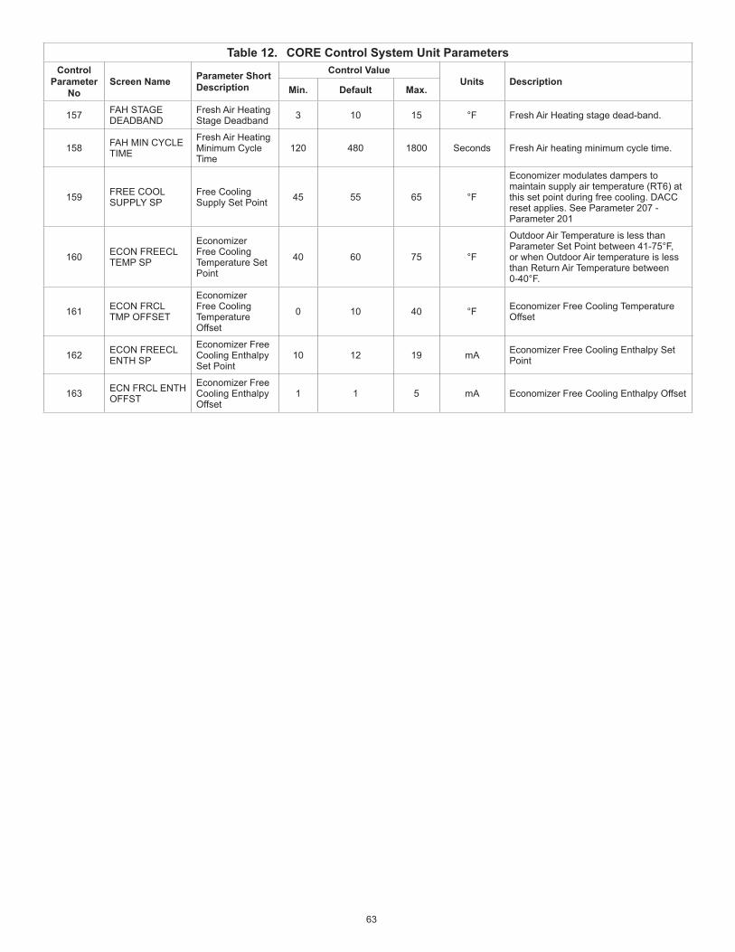
63
Table 12. CORE Control System Unit ParametersControl
Parameter No
Screen Name Parameter Short Description
Control ValueUnits Description
Min. Default Max.
157 FAH STAGE DEADBAND
Fresh Air Heating Stage Deadband 3 10 15 °F Fresh Air Heating stage dead-band.
158 FAH MIN CYCLE TIME
Fresh Air Heating Minimum Cycle Time
120 480 1800 Seconds Fresh Air heating minimum cycle time.
159 FREE COOL SUPPLY SP
Free Cooling Supply Set Point 45 55 65 °F
Economizer modulates dampers to maintain supply air temperature (RT6) at this set point during free cooling. DACC reset applies. See Parameter 207 - Parameter 201
160 ECON FREECL TEMP SP
Economizer Free Cooling Temperature Set Point
40 60 75 °F
Outdoor Air Temperature is less than Parameter Set Point between 41-75°F, or when Outdoor Air temperature is less than Return Air Temperature between 0-40°F.
161 ECON FRCL TMP OFFSET
Economizer Free Cooling Temperature Offset
0 10 40 °F Economizer Free Cooling Temperature Offset
162 ECON FREECL ENTH SP
Economizer Free Cooling Enthalpy Set Point
10 12 19 mA Economizer Free Cooling Enthalpy Set Point
163 ECN FRCL ENTH OFFST
Economizer Free Cooling Enthalpy Offset
1 1 5 mA Economizer Free Cooling Enthalpy Offset

64
Table 12. CORE Control System Unit ParametersControl
Parameter No
Screen Name Parameter Short Description
Control ValueUnits Description
Min. Default Max.
164 ECONOMIZER PROFILE
Economizer Profile 0 2 3 Option
Thesearetheoperatingprofileoptionsfor the economizer damper during free cooling when any compressor is on and can be selected as follows:• Option 0: Damper continues to
modulate while compressors are on, but the effect of mechanical cooling may force the damper closed to its minimum position. After compressor starts, the free cooling setpoint is loweredtoafixedtemperatureof45°F.
• Option 1: Damper opens to its max open position (Parameter 131 - FREE CL MAX DAMPER) when any compressors start.
NOTE: When using Option 1 and after the compressor is stopped, the M3 will resume damper modulation.
• Option 2: Damper continues to modulate while compressors are on, but the effect of mechanical cooling may force the damper closed to its minimum position. This is the factory default setting.
> Holds off compressor on Y2 call until damper has modulated to maximum position (Parameter 131 - FREE CL MAX DAMPER) for three minutes.
> After three minutes, compressor starts and the free cooling setpoint is lowered to 45°F. Damper is not locked at maximum open while compressor is on, but modulates to maintain 45°F discharge air temperature.
> WhenY2issatisfied,compressor goes off and free cooling setpoint is restored to 55°F (Parameter 159 - FREE COOL SUPPLY SP).
• Option 3: Same as Option 2, but with a 10 minute delay instead of a three minute delay.
System 2 Parameters
165 FAH STAGE DIFFER
Fresh Air Heating Stage Differential 0 2 20 °F
• Fresh Air Heating stage differential.
• 0valueforfirststageheatingonlyfor Fresh Air Heating.
166 FAH REHEAT OAT SP
Fresh Air Heating Control Reheat Outdoor Air Temperature Set Point
20 45 60 °F
Outdoor air temperature set point that enables fresh air heating for reheat demand and opens damper to Parameter 167 when outdoor air is less than set point.
167 FAH REHEAT DAMPER
Fresh Air Heating Control Reheat Damper Position
5 40 100 % Fresh air damper position during Fresh Air Heating reheat operation.
168 FAH REHEAT SP Fresh Air Heat Control Set Point 40 40 70 °F Fresh Air Heating Reheat set point.

65
Table 12. CORE Control System Unit ParametersControl
Parameter No
Screen Name Parameter Short Description
Control ValueUnits Description
Min. Default Max.
169 FAT AUTO CHGOVR DLY
Fresh Air Tempering Automatic Changeover Delay
15 30 120 MinutesFresh Air Heating Control or Fresh Air Cooling Control air Tempering auto-changeover delay.
170 FRESH AIR COOL SP
See CORE System Application Guide for further details and to change the fresh air cool (FAC) set point. Modify the set point only using the method described in the reference section.
171 FAC STAGE DEADBAND
Fresh Air Cooling Control Deadband 3 10 15 °F Fresh Air Cooling stage dead-band.
172 FAC MIN CYCLE TIME
Fresh Air Cooling Control Cycle Time
120 480 1800 Seconds Fresh Air Cooling minimum cycle time.
173 FAC STAGE DIFFER
Fresh Air Cooling Control Stage Differential
0 2 20 °F
• Fresh Air Cooling stage differential between stages.
• Setto0forfirststagecoolingonlyfor Fresh Air Cooling.
174 DACH OCC SETPOINT
Discharge Air Control Heating Occupied Set Point
60 110 140 °F Discharge Air Control Heating set point during occupied period.
175 DACH UNOCC SETPOINT
Discharge Air Control Heating Unoccupied Set Point
60 95 140 °F Discharge Air Control Heating set point during unoccupied period.
176 DACH STAGE DEADBAND
Discharge Air Control Heating Stage Deadband
5 5 20 °F Discharge Air Control Heating dead-band.
177 DACH FAH STG UP TMR
Discharge Air Control Heating Stage-Up Time Delay
0 180 900 Seconds Discharge Air Control Heating and Fresh Air Heating stage-up time delay.
178 DACH FAH STG DN TMR
Discharge Air Control Heating and Fresh Air Heating Control Stage-Down Time Delay
0 120 600 Seconds Discharge Air Control Heating and Fresh Air Heating stage-down time delay.
179 DACH STAGE DIFFER
Discharge Air Control Heating Stage Differential
2 2 20 °F Discharge Air Control Heating stage differential
180 DACC OCC SETPOINT
Discharge Air Control Cooling Occupied Set Point
40 55 80 °F Discharge Air Control Cooling set point during occupied period.
181 DACC UNOCC SETPOINT
Discharge Air Control Cooling Unoccupied Set Point
40 65 100 °F Discharge Air Control Cooling set point during unoccupied period.
182 DACC STAGE DEADBAND
Discharge Air Control Cooling Deadband Set Point
5 5 20 °F Discharge Air Control Cooling stage dead-band.
183 DACC FAC STG UP TMR
Discharge Air Control Cooling and Fresh Air Cooling Stage-Up Delay
0 180 900 Seconds Discharge Air Control Cooling and Fresh Air Cooling stage-up delay.
184 DACC FAC STG DN TMR
Discharge Air Control Cooling and Fresh Air Cooling Stage-Down Time Delay
0 120 600 Seconds Discharge Air Control Cooling and Fresh Air Cooling stage-down time delay.

66
Table 12. CORE Control System Unit ParametersControl
Parameter No
Screen Name Parameter Short Description
Control ValueUnits Description
Min. Default Max.
185 DACC STAGE DIFFER
Discharge Air Cooling Stage Differential
2 2 20 °F Discharge Air Cooling stage differential.
186 SRV OUTPT CTRL MODE
Service Output Control Mode 0 0 127 Option
A55 Service Output Control Mode = X + 32*Y + 16*ZInput source = X:• 0 = None
• 1 = Compressor 1 duty cycle. (Compressor crankcase heater function.)
> On when outdoor air temperature is less than or equal to Parameter 189 and greater than or equal to Parameter 192 seconds have passed with compressor 1 off.
> Off when Outdoor Air temperature is greater than Parameter189plus3°F(fixeddead-band) or is less than Parameter 192 seconds have passed with compressor 1 off
• 2 = On when occupied.
• 3 = On when blower on,
• 4 = On when heating demand.
• 5 = On when cooling demand.
• 6 = On when heating or cooling demand.
• 7 = System Relative Humidity (A55_P298_5 RH)
• 8 = System Indoor Air Quality. (A55_P298_3 IAQ)
• 9 = System Outdoor Air Temperature (A55_P267_1/2 OAT)
• 10 = Energy Recovery System
• 11 = SCR Option for Electric Heat
Algorithm Y for input sources 7 - 9:• 0 = Hysteresis loop (see sections
14.2 - 14.4)
• 1 = Window - On when input is in range; (see sections 14.2 - 14.4)
• 2 = Delayed-on. (see sections 14.2 - 14.4)
• 3 = Delayed-off. (see sections 14.2 - 14.4)
Inversion Z:• 0- Output not inverted.
• 1- Output inverted.
187 SRV OUTPT SP C02
Service Output Set Point for Carbon Dioxide
0 996 2000 ppm A55 service relay output set point.
188 SRV OUTPT SP RH
Service Output Set Point for Relative Humidity
0 100 100 % Service Output Set Point for Relative Humidity
189 SRV OUTPT SP TEMP
Service Output Set Point Temperature
-31 51 132 °F Service Output Set Point Temperature
190 SRV OUTPT DB C02
Service Output Deadband for Carbon Dioxide
16 102 2000 ppm A55 service relay output dead-band or delay.

67
Table 12. CORE Control System Unit ParametersControl
Parameter No
Screen Name Parameter Short Description
Control ValueUnits Description
Min. Default Max.
191 SRV OUTPT DB RH
Service Output Deadband for Relative Humidity
2 13 100 % Service Output Deadband for Relative Humidity
192 SRV OUTPT DB TEMP
Service Output Deadband for Temperature
1 8 162 °F Service Output Deadband for Temperature
193 SRV OUTPT DELAY
Service Output Delay 64 416 8160 Seconds Service Output Delay
194 LOAD SHED NUM COMP
Number of compressors to shed during load shedding
0 0 4 Option
Number of compressors to be turned off when load shedding is active.ApplicabletoStandardEfficiency3-to6-ton units only. 2-stage compressor, a value of one shuts off 2nd stage only and a value of 2 turns compressor completely off.
196 MAC ADDRESS MAC Address 0 128 128 AddressBACnet MAC Address. A value of 0-128 sets the BACnet MAC address to that value.
197 BAUD RATE Baud Rate
9.6K19.2K38.4K76.8K
Option Baud rate setting.
System 3 Parameters
201 DACC OAT RS ADJ BND
Discharge Air Control Cooling Outdoor Air Temperature Adjustment Band
0 0 30 °F
• Discharge Air Control Cooling outdoor temperature ambient cooling adjustment reset band.
• Also used to reset free cooling set point (Parameter 159).
202 DACC OAT RS ADJ SP
Discharge Air Control Cooling Outdoor Air Temperature Cooling Reset Set Point
40 80 100 °F
• Discharge Air Control Cooling outdoor air temperature cooling reset set point.
• Also used to reset free cooling set point (Parameter 159).
203 DACC OAT RS PRP BND
Discharge Air Control Cooling Outdoor Ambient Air Temperature Cooling Proportional Band
1 20 60 °F
• Discharge Air Control Cooling outdoor ambient temperature cooling proportional band.
• Also used to reset free cooling set point (Parameter 159).
204 DACC RAT RS ADJ BND
Discharge Air Control Cooling Return Air Reset Adjustment Band
0 0 30 °F
• Discharge Air Control Cooling return air reset adjustment band. 0 disables return air cooling reset.
• Also used to reset free cooling set point (Parameter 159).
205 DACC RAT RS ADJ SP
Discharge Air Control Return Air Reset Adjustment Set Point
50 70 80 °F
• Discharge Air Control Cooling return air reset set point.
• Also used to reset free cooling set point (Parameter 159).
206 DACC RAT RS PRP BND
Discharge Air Control Cooling Return Air Reset Proportional Band
1 10 30 °F
• Discharge Air Control Cooling return air reset proportional band.
• Also used to reset free cooling set point (Parameter 159).
207 DACC RS LIMITDischarge Air Control Cooling Reset Limit
5 10 20 °F
• Discharge Air Control Cooling total reset limit. This limits the total DACC reset allowed.
• Also used to reset free cooling set point (Parameter 159).

68
Table 12. CORE Control System Unit ParametersControl
Parameter No
Screen Name Parameter Short Description
Control ValueUnits Description
Min. Default Max.
208 DACH OAT RS ADJ BND
Discharge Air Control Heating Outdoor Air Temperature Reset Adjustment Band
0 0 30 °F Discharge Air Control Heating outdoor temperature reset adjustment band.
209 DACH OAT RS ADJ SP
Discharge Air Control Heating Reset Adjustment Set Point
-31 40 60 °F Discharge Air Control Heating outdoor temperature reset set point.
210 DACH OAT RS PRP BND
Discharge Air Control Heating Outdoor Air Temperature Reset Proportional Band
1 20 60 °F Discharge Air Control Heating temperature reset proportional band.
211 DACH RAT RS ADJ BND
Discharge Air Control Heating Return Air Temperature Adjustment Band
0 0 30 °F Discharge Air Control Heating return reset adjustment band.
212 DACH RAT RS ADJ SP
Discharge Air Control heating Return Air Heating Reset Set Point
50 70 80 °F Discharge Air Control Heating return air heating reset set point.
213 DACH RAT RS PRP BND
Discharge Air Control Heating Return Air Heading Reset Proportional Band
1 10 30 °F Discharge Air Control Heating return air heating reset proportional band.
214 DACH RS LIMIT
Discharge Air Control Heating Return Air Heating Reset Limit
5 10 20 °F Discharge Air Control Heating reset limit. This limits the total DACH reset allowed.
215 EXH FN STG1 DAMP SP
Exhaust Fan Stage 1 Damper Set Point
0 50 100 % Exhaust fan stage 1 damper set point.
216 EXH FN STG1 DAMP DB
Exhaust Fan Stage 1 Damper Deadband
0Default may be altered at factory test.
100 % Exhaust Fan Stage 1 Damper Deadband
217
EXH FN STG1 PRES SPorVFD PE PRES SP
Stage 1 set pointorVFD PE set point
-0.5 0.05 0.5 in w.c.
Exhaust Fan Stage 1 Pressure Set Point.orVFD Power Exhaust Building Pressure Set Point.
218 EXH FN STG1 PRES DB
Stage 1 deadband 0 0.02 1 in w.c. Exhaust Fan Stage 1 Pressure
Deadband.
219 EXH FN STG2 DAMP SP
Exhaust Fan Stage 2 Damper Set Point
0 75 100 % Exhaust Fan Stage 2 Damper Set Point
220 EXH FN STG2 DAMP DB
Exhaust Fan Stage 2 Damper Deadband
0 10 100 % Exhaust Fan Stage 2 Damper Deadband
221 EXH FN STG2 PRES SP Stage 2 setpoint -0.5 0.10 0.5 in w.c. Exhaust Fan Stage 2 Pressure Set Point
222 EXH FN STG2 PRES DB
Stage 2 deadband 0 0.05 1 in w.c. Exhaust Fan Stage 2 Pressure
Deadband.
223 EXH FAN STGUP DELAY
Exhaust Fan Stage Up Delay 0 100 300 Seconds Exhaust Fan Stage Up Delay
224 EXH FAN STGDWN DLAY
Exhaust Fan Stage Down Delay
0 100 200 Seconds Stage 1 off-delay. (Only used for 2 stage operation)
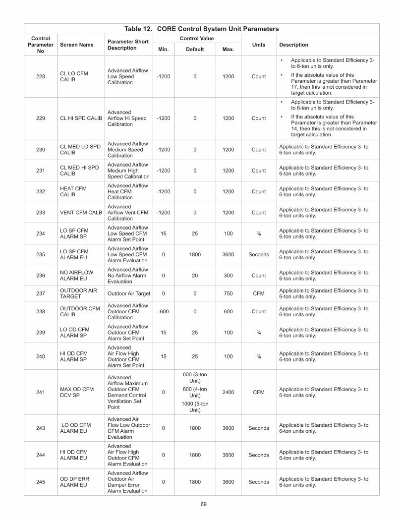
69
Table 12. CORE Control System Unit ParametersControl
Parameter No
Screen Name Parameter Short Description
Control ValueUnits Description
Min. Default Max.
228 CL LO CFM CALIB
AdvancedAirflowLow Speed Calibration
-1200 0 1200 Count
• ApplicabletoStandardEfficiency3-to 6-ton units only.
• If the absolute value of this Parameter is greater than Parameter 17. then this is not considered in target calculation.
229 CL HI SPD CALIBAdvanced AirflowHiSpeedCalibration
-1200 0 1200 Count
• ApplicabletoStandardEfficiency3-to 6-ton units only.
• If the absolute value of this Parameter is greater than Parameter 14, then this is not considered in target calculation
230 CL MED LO SPD CALIB
AdvancedAirflowMedium Speed Calibration
-1200 0 1200 Count ApplicabletoStandardEfficiency3-to6-ton units only.
231 CL MED HI SPD CALIB
AdvancedAirflowMedium High Speed Calibration
-1200 0 1200 Count ApplicabletoStandardEfficiency3-to6-ton units only.
232 HEAT CFM CALIB
AdvancedAirflowHeat CFM Calibration
-1200 0 1200 Count ApplicabletoStandardEfficiency3-to6-ton units only.
233 VENT CFM CALBAdvanced AirflowVentCFMCalibration
-1200 0 1200 Count ApplicabletoStandardEfficiency3-to6-ton units only.
234 LO SP CFM ALARM SP
AdvancedAirflowLow Speed CFM Alarm Set Point
15 25 100 % ApplicabletoStandardEfficiency3-to6-ton units only.
235 LO SP CFM ALARM EU
AdvancedAirflowLow Speed CFM Alarm Evaluation
0 1800 3600 Seconds ApplicabletoStandardEfficiency3-to6-ton units only.
236 NO AIRFLOW ALARM EU
AdvancedAirflowNoAirflowAlarmEvaluation
0 20 300 Count ApplicabletoStandardEfficiency3-to6-ton units only.
237 OUTDOOR AIR TARGET Outdoor Air Target 0 0 750 CFM ApplicabletoStandardEfficiency3-to
6-ton units only.
238 OUTDOOR CFM CALIB
AdvancedAirflowOutdoor CFM Calibration
-600 0 600 Count ApplicabletoStandardEfficiency3-to6-ton units only.
239 LO OD CFM ALARM SP
AdvancedAirflowOutdoor CFM Alarm Set Point
15 25 100 % ApplicabletoStandardEfficiency3-to6-ton units only.
240 HI OD CFM ALARM SP
Advanced Air Flow High Outdoor CFM Alarm Set Point
15 25 100 % ApplicabletoStandardEfficiency3-to6-ton units only.
241 MAX OD CFM DCV SP
Advanced AirflowMaximumOutdoor CFM Demand Control Ventilation Set Point
0
600 (3-ton Unit)
800 (4-ton Unit)
1000 (5-ton Unit)
2400 CFM ApplicabletoStandardEfficiency3-to6-ton units only.
243 LO OD CFM ALARM EU
Advanced Air Flow Low Outdoor CFM Alarm Evaluation
0 1800 3600 Seconds ApplicabletoStandardEfficiency3-to6-ton units only.
244 HI OD CFM ALARM EU
Advanced Air Flow High Outdoor CFM Alarm Evaluation
0 1800 3600 Seconds ApplicabletoStandardEfficiency3-to6-ton units only.
245 OD DP ERR ALARM EU
AdvancedAirflowOutdoor Air Damper Error Alarm Evaluation
0 1800 3600 Seconds ApplicabletoStandardEfficiency3-to6-ton units only.

70
Table 12. CORE Control System Unit ParametersControl
Parameter No
Screen Name Parameter Short Description
Control ValueUnits Description
Min. Default Max.
246 ALTITUDE STPT AdvancedAirflowAltitude Set Point 0 650 25000 Feet ApplicabletoStandardEfficiency3-to
6-ton units only.
247 BLR CALIB RAMP RATE
Blower Calibration Ramp Rate 4 10 40 % ApplicabletoStandardEfficiency3-to
6-ton units only.
258 DISPLAY UNITS F/C
Display Unit (Fahrenheit or Celsius)
FAHRENHEIT or
CELSIUSOption Temperature unit of measurement.
285 FRCL COMP LCKOUT MD
Free Cooling Compressor Lockout Mode
0 2 2 Option
• 0 = Disable Free Cooling Low Ambient Compressor Lockout (default).
• 1 = Lockout Compressor whenever the outdoor air is suitable regardless of outdoor air temperature.
• 2 = Enable Free Cooling Low Ambient Compressor Lockout.
287 ALGORITHMS ENABLED
Algorithms Enabled
NOTE: Options for Parameter 287 are not accessible via the CORE Unit Controller user interface. Options can be set using the Lennox UC software.
Here is an example of the selection options for Algorithms Enable via the Lennox UC Software:Set Bit Description0x00000002 Enable Fresh Air Heating (ALGO_FAH)0x00000004 Enable Fresh Air Cooling (ALGO_FAC)0x00000008 Enable DACC Return Air Reset (ALGO_DACC_RAT_RESET)0x00000010 Enable DACC Outdoor Air Reset (ALGO_DACC_OAT_RESET)0x00000020 Enable DACH Return Air Reset (ALGO_DACH_RAT_RESET)0x00000040 Enable DACH Outdoor Air Reset (ALGO_DACH_OAT_RESET)0x00000080 Enable Supply Static Pressure Sensor Alarm (ALGO_LO_STATIC_PRESSURE_ALARM)0x00000100 Enable Low Outdoor Temp override of DCV/OAC operation (ALGO_LO_OAT_DCV_OAC_OVERRIDE)0x00000200 Enable High Outdoor Temp override of DCV/OAC operation (ALGO_HI_OAT_DCV_OAC_OVERRIDE)0x00000800 Enable Free Cooling Blower Stage Up.
305LON HEARTBEAT TIME
LonTalk Heartbeat Time 0 100 10,000 Seconds
Heartbeatconfigurationproprietiesdefinehow often a network variable update is transmitted from a sending node.
313 FAH REHEAT MODE
Fresh Air Reheat Mode 0 0 3 Option
• 0 = Disabled
• 1 = Allowed, must be occupied
• 2 = Allowed, blower must be energized and in occupied mode.
• 3 = Allow. No conditions apply.
314 MSAV MIN VFD DR OUT
MSAV Minimum VFD Drive Output 10 33 50 %
The CORE Unit Controller will ensure that active VFD drive output is equal or greater than Minimum VFD drive output. If conversion from CFM setting to VFD drive yields lower value. The system will use Minimum VFD drive output instead output.
317 OUT AIR UNIT OPTNS
Outdoor Air Unit Options 0 0 2 Option
This Parameter is applicable in Zone Sensor mode (i.e. not applicable for local/remote thermostat mode).
321 ENTH HIGH TMP LIMT
Enthalpy High Temperature Limit 45 75 85 °F
When in Enthalpy mode, the outdoor air suitability (OAS) will be set only if the outdoor air temperature is lesser than this Parameter set point.
323 ZON SNSR CAL OFFSET
Zone Sensor Calibration Offset -5 0 5 °F This setting is applicable to local
temperature sensor only.
327 BPC MANUAL RESET
Building Pressure Control Manual Reset
0 50 100 %Manual reset value. This Parameter definesthedefaultoutdoorairdamperposition
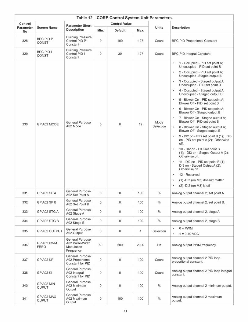
71
Table 12. CORE Control System Unit ParametersControl
Parameter No
Screen Name Parameter Short Description
Control ValueUnits Description
Min. Default Max.
328 BPC PID P CONST
Building Pressure Control PID P Constant
0 100 127 Count BPC PID Proportional Constant
329 BPC PID I CONST
Building Pressure Control PID I Constant
0 30 127 Count BPC PID Integral Constant
330 GP A02 MODE General Purpose A02 Mode 0 0 12 Mode
Selection
• 1 - Occupied - PID set point A; Unoccupied - PID set point B
• 2 - Occupied - PID set point A; Unoccupied -Staged output B
• 3 - Occupied - Staged output A; Unoccupied - PID set point B
• 4 - Occupied - Staged output A; Unoccupied - Staged output B
• 5 - Blower On - PID set point A; Blower Off - PID set point B
• 6 - Blower On - PID set point A; Blower Off - Staged output B
• 7 - Blower On - Staged output A; Blower Off - PID set point B
• 8 - Blower On - Staged output A; Blower Off - Staged output B
• 9 - DI2 on - PID set point B (1); DI3 on - PID set point A (2); Otherwise off.
• 10 - DI2 on - PID set point B (1); DI3 on - Staged Output A (2); Otherwise off.
• 11 - DI2 on - PID set point B (1); DI3 on - Staged Output A (2); Otherwise off.
• 12 - Reserved
• (1) -DI3 (on M3) doesn’t matter
• (2) -DI2 (on M3) is off
331 GP A02 SP A General Purpose A02 Set Point A 0 0 100 % Analog output channel 2, set point A.
332 GP A02 SP B General Purpose A02 Set Point B 0 0 100 % Analog output channel 2, set point B.
333 GP A02 STG A General Purpose A02 Stage A 0 0 100 % Analog output channel 2, stage A
334 GP A02 STG B General Purpose A02 Stage B 0 0 100 % Analog output channel 2, stage B
335 GP A02 OUTPUT General Purpose A02 Output 0 0 1 Selection
• 0 = PWM
• 1 = 0-10 VDC
336 GP A02 PWM FREQ
General Purpose A02 Pulse-Width Modulation Frequency
50 200 2000 Hz Analog output PWM frequency.
337 GP A02 KPGeneral Purpose A02 Proportional Constant for PID
0 0 100 Count Analog output channel 2 PID loop proportional constant.
338 GP A02 KIGeneral Purpose A02 Integral Constant for PID
0 0 100 Count Analog output channel 2 PID loop integral constant.
340 GP A02 MIN OUPUT
General Purpose A02 Minimum Output
0 0 100 % Analog output channel 2 minimum output.
341 GP A02 MAX OUPUT
General Purpose A02 Maximum Output
0 100 100 % Analog output channel 2 maximum output.

72
Table 12. CORE Control System Unit ParametersControl
Parameter No
Screen Name Parameter Short Description
Control ValueUnits Description
Min. Default Max.
342 GP A02 SOURCE General Purpose A02 Source 1 1 3 Selection
Source/feedback for the PID loop.• 1 = Analog input 1 on GP3 A02
• 2 = Analog input 2 on GP3 A02
• 3 = Analog input 3 on GP3 A02
343 GP A02 CYCL INTRVL
General Purpose A02 Cycle Interval 0 1 180 Seconds Frequency of execution of PID loop.
344 GP A03 MODE General Purpose A03 Mode 0 0 11 Mode
Selection
• 1 - Occupied - PID set point A; Unoccupied - PID set point B
• 2 - Occupied - PID set point A; Unoccupied -Staged output B
• 3 - Occupied - Staged output A; Unoccupied - PID set point B
• 4 - Occupied - Staged output A; Unoccupied - Staged output B
• 5 - Blower On - PID set point A; Blower Off - PID set point B
• 6 - Blower On - PID set point A; Blower Off - Staged output B
• 7 - Blower On - Staged output A; Blower Off - PID set point B
• 8 - Blower On - Staged output A; Blower Off - Staged output B
• 9 - DI2 on - PID set point B (1); DI3 on - PID set point A (2); Otherwise off.
• 10 - DI2 on - PID set point B (1); DI3 on - Staged Output A (2); Otherwise off.
• 11 - DI2 on - PID set point B (1); DI3 on - Staged Output A (2); Otherwise off.
• 12 - Reserved
• (1) -DI3 (on M3) doesn’t matter
• (2) -DI2 (on M3) is off
345 GP A03 SP A General Purpose A03 Set Point A 0 0 100 % Analog output channel 3, set point A.
346 GP A03 SP B General Purpose A03 Set Point B 0 0 100 % Analog output channel 3, set point B.
347 GP A03 STG A General Purpose A03 Stage A 0 0 100 % Analog output channel 3, stage A
348 GP A03 STG B General Purpose A02 Stage B 0 0 100 % Analog output channel 3, stage B
349 GP A03 OUTPUT General Purpose A03 Output 0 0 1 Selection
• 0 = PWM
• 1 = 0-10 VDC
350 GP A03 PWM FREQ
General Purpose A03 Pulse-Width Modulation Frequency
50 200 2000 Hz Frequency of execution of PID loop.
351 GP A03 KPGeneral Purpose A03 Proportional Constant
0 0 100 Count Analog output channel 3 PID loop proportional constant.
352 GP A03 KIGeneral Purpose A03 Integral Constant
0 0 100 Count Analog output channel 3 PID loop integral constant.
354 GP A03 MIN OUPUT
General Purpose A03 Minimum Output
0 0 100 % Analog output channel 3 minimum output.
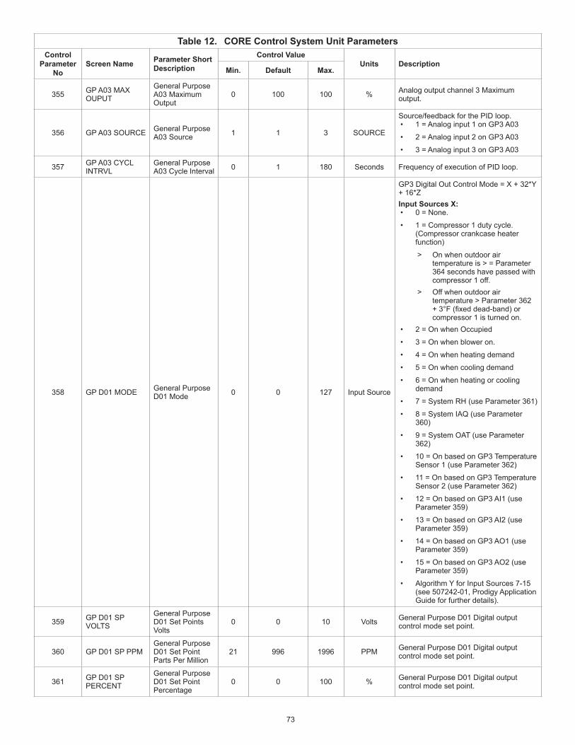
73
Table 12. CORE Control System Unit ParametersControl
Parameter No
Screen Name Parameter Short Description
Control ValueUnits Description
Min. Default Max.
355 GP A03 MAX OUPUT
General Purpose A03 Maximum Output
0 100 100 % Analog output channel 3 Maximum output.
356 GP A03 SOURCE General Purpose A03 Source 1 1 3 SOURCE
Source/feedback for the PID loop.• 1 = Analog input 1 on GP3 A03
• 2 = Analog input 2 on GP3 A03
• 3 = Analog input 3 on GP3 A03
357 GP A03 CYCL INTRVL
General Purpose A03 Cycle Interval 0 1 180 Seconds Frequency of execution of PID loop.
358 GP D01 MODE General Purpose D01 Mode 0 0 127 Input Source
GP3 Digital Out Control Mode = X + 32*Y + 16*ZInput Sources X:• 0 = None.
• 1 = Compressor 1 duty cycle. (Compressor crankcase heater function)
> On when outdoor air temperature is > = Parameter 364 seconds have passed with compressor 1 off.
> Off when outdoor air temperature > Parameter 362 +3°F(fixeddead-band)orcompressor 1 is turned on.
• 2 = On when Occupied
• 3 = On when blower on.
• 4 = On when heating demand
• 5 = On when cooling demand
• 6 = On when heating or cooling demand
• 7 = System RH (use Parameter 361)
• 8 = System IAQ (use Parameter 360)
• 9 = System OAT (use Parameter 362)
• 10 = On based on GP3 Temperature Sensor 1 (use Parameter 362)
• 11 = On based on GP3 Temperature Sensor 2 (use Parameter 362)
• 12 = On based on GP3 AI1 (use Parameter 359)
• 13 = On based on GP3 AI2 (use Parameter 359)
• 14 = On based on GP3 AO1 (use Parameter 359)
• 15 = On based on GP3 AO2 (use Parameter 359)
• Algorithm Y for Input Sources 7-15 (see 507242-01, Prodigy Application Guide for further details).
359 GP D01 SP VOLTS
General Purpose D01 Set Points Volts
0 0 10 Volts General Purpose D01 Digital output control mode set point.
360 GP D01 SP PPMGeneral Purpose D01 Set Point Parts Per Million
21 996 1996 PPM General Purpose D01 Digital output control mode set point.
361 GP D01 SP PERCENT
General Purpose D01 Set Point Percentage
0 0 100 % General Purpose D01 Digital output control mode set point.

74
Table 12. CORE Control System Unit ParametersControl
Parameter No
Screen Name Parameter Short Description
Control ValueUnits Description
Min. Default Max.
362 GP DO1 SP DEGREES
General Purpose D01 Set Point Degree
-31 0 132 °F General Purpose D01 Digital output control mode set point.
363 GP D01 DB PERCENT
General Purpose D01 Dead Band Percentage
0 0 100 %
General Purpose D01 Digital output control mode set point. EXAMPLE: If this Parameter is set
to 10%, then the dead-band in Fahrenheit would be (DO Temperature Set Point * 10 /100).
364 GP D01 TIME DELAY
General Purpose D01 Time Delay 1 416 8160 Seconds For delay on or delay off.
365 GP D02 MODE General Purpose D02 Mode 0 0 127 Mode
Selection
GP3 Digital Out Control Mode = X + 32*Y + 16*ZInput Sources X:• 0 = None.
• 1 = Compressor 1 duty cycle. (Compressor crankcase heater function)
> On when outdoor air temperatureis<=Parameter369 and > = P 371 seconds have passed with compressor 1 off.
> Off when outdoor air temperature > Parameter 369 +3°F(fixeddead-band)orcompressor 1 is turned on.
• 2 = On when Occupied
• 3 = On when blower on.
• 4 = On when heating demand
• 5 = On when cooling demand
• 6 = On when heating or cooling demand
• 7 = System RH (use Parameter 368)
• 8 = System IAQ (use Parameter 367)
• 9 = System OAT (use Parameter 369)
• 10 = On based on GP3 Temperature Sensor 1 (use Parameter 369)
• 11 = On based on GP3 Temperature Sensor 2 (use Parameter 369)
• 12 = On based on GP3 AI1 (use Parameter 366)
• 13 = On based on GP3 AI2 (use Parameter 366)
• 14 = On based on GP3 AO1 (use Parameter 366)
• 15 = On based on GP3 AO2 (use Parameter 366)
• Algorithm Y for Input Sources 7-15 (see 507242-01, Prodigy Application Guide for further details).
366 GP D02 SP VOLTS
General Purpose D02 Set Point Volts
0 0 10 Volts General Purpose D02 Digital output control mode set point.
367 GP D02 SP PPMGeneral Purpose D02 Set Point Parts Per Million
21 996 1996 PPM General Purpose D02 Digital output control mode set point.
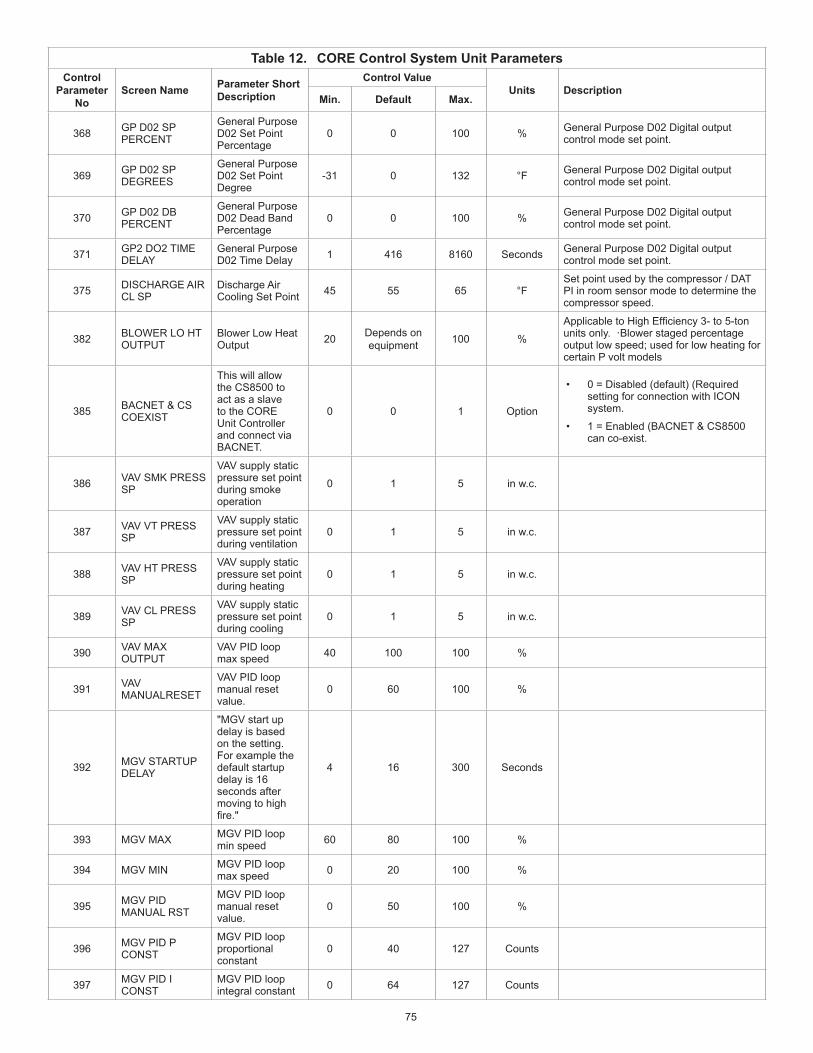
75
Table 12. CORE Control System Unit ParametersControl
Parameter No
Screen Name Parameter Short Description
Control ValueUnits Description
Min. Default Max.
368 GP D02 SP PERCENT
General Purpose D02 Set Point Percentage
0 0 100 % General Purpose D02 Digital output control mode set point.
369 GP D02 SP DEGREES
General Purpose D02 Set Point Degree
-31 0 132 °F General Purpose D02 Digital output control mode set point.
370 GP D02 DB PERCENT
General Purpose D02 Dead Band Percentage
0 0 100 % General Purpose D02 Digital output control mode set point.
371 GP2 DO2 TIME DELAY
General Purpose D02 Time Delay 1 416 8160 Seconds General Purpose D02 Digital output
control mode set point.
375 DISCHARGE AIR CL SP
Discharge Air Cooling Set Point 45 55 65 °F
Set point used by the compressor / DAT PI in room sensor mode to determine the compressor speed.
382 BLOWER LO HT OUTPUT
Blower Low Heat Output 20 Depends on
equipment 100 %
ApplicabletoHighEfficiency3-to5-tonunits only. ·Blower staged percentage output low speed; used for low heating for certain P volt models
385 BACNET & CS COEXIST
This will allow the CS8500 to act as a slave to the CORE Unit Controller and connect via BACNET.
0 0 1 Option
• 0 = Disabled (default) (Required setting for connection with ICON system.
• 1 = Enabled (BACNET & CS8500 can co-exist.
386 VAV SMK PRESS SP
VAV supply static pressure set point during smoke operation
0 1 5 in w.c.
387 VAV VT PRESS SP
VAV supply static pressure set point during ventilation
0 1 5 in w.c.
388 VAV HT PRESS SP
VAV supply static pressure set point during heating
0 1 5 in w.c.
389 VAV CL PRESS SP
VAV supply static pressure set point during cooling
0 1 5 in w.c.
390 VAV MAX OUTPUT
VAV PID loop max speed 40 100 100 %
391 VAV MANUALRESET
VAV PID loop manual reset value.
0 60 100 %
392 MGV STARTUP DELAY
"MGV start up delay is based on the setting. For example the default startup delay is 16 seconds after moving to high fire."
4 16 300 Seconds
393 MGV MAX MGV PID loop min speed 60 80 100 %
394 MGV MIN MGV PID loop max speed 0 20 100 %
395 MGV PID MANUAL RST
MGV PID loop manual reset value.
0 50 100 %
396 MGV PID P CONST
MGV PID loop proportional constant
0 40 127 Counts
397 MGV PID I CONST
MGV PID loop integral constant 0 64 127 Counts
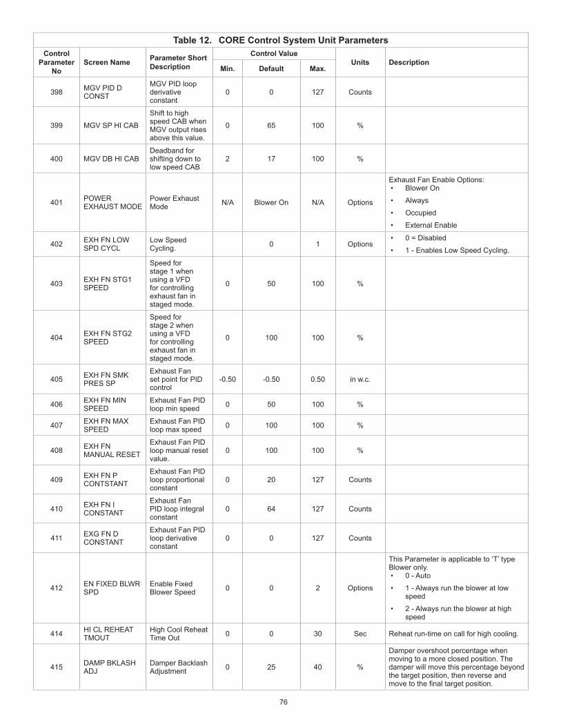
76
Table 12. CORE Control System Unit ParametersControl
Parameter No
Screen Name Parameter Short Description
Control ValueUnits Description
Min. Default Max.
398 MGV PID D CONST
MGV PID loop derivative constant
0 0 127 Counts
399 MGV SP HI CAB
Shift to high speed CAB when MGV output rises above this value.
0 65 100 %
400 MGV DB HI CAB Deadband for shifting down to low speed CAB
2 17 100 %
401 POWER EXHAUST MODE
Power Exhaust Mode N/A Blower On N/A Options
Exhaust Fan Enable Options:• Blower On
• Always
• Occupied
• External Enable
402 EXH FN LOW SPD CYCL
Low Speed Cycling. 0 1 Options
• 0 = Disabled
• 1 - Enables Low Speed Cycling.
403 EXH FN STG1 SPEED
Speed for stage 1 when using a VFD for controlling exhaust fan in staged mode.
0 50 100 %
404 EXH FN STG2 SPEED
Speed for stage 2 when using a VFD for controlling exhaust fan in staged mode.
0 100 100 %
405 EXH FN SMK PRES SP
Exhaust Fan set point for PID control
-0.50 -0.50 0.50 in w.c.
406 EXH FN MIN SPEED
Exhaust Fan PID loop min speed 0 50 100 %
407 EXH FN MAX SPEED
Exhaust Fan PID loop max speed 0 100 100 %
408 EXH FN MANUAL RESET
Exhaust Fan PID loop manual reset value.
0 100 100 %
409 EXH FN P CONTSTANT
Exhaust Fan PID loop proportional constant
0 20 127 Counts
410 EXH FN I CONSTANT
Exhaust Fan PID loop integral constant
0 64 127 Counts
411 EXG FN D CONSTANT
Exhaust Fan PID loop derivative constant
0 0 127 Counts
412 EN FIXED BLWR SPD
Enable Fixed Blower Speed 0 0 2 Options
This Parameter is applicable to ‘T’ type Blower only.• 0 - Auto
• 1 - Always run the blower at low speed
• 2 - Always run the blower at high speed
414 HI CL REHEAT TMOUT
High Cool Reheat Time Out 0 0 30 Sec Reheat run-time on call for high cooling.
415 DAMP BKLASH ADJ
Damper Backlash Adjustment 0 25 40 %
Damper overshoot percentage when moving to a more closed position. The damper will move this percentage beyond the target position, then reverse and movetothefinaltargetposition.

77
Table 12. CORE Control System Unit ParametersControl
Parameter No
Screen Name Parameter Short Description
Control ValueUnits Description
Min. Default Max.
416 BLOWER COOL OUTPUT
Blower Cooling High 20 Depends on
equipment 100 %
ApplicabletoHighEfficiency3-to5-tonunits only. Blower staged percentage output high speed; used for high cooling or ventilation,

78
16. CORE Control System Inputs and Outputs
16.1. CORE Unit Controller (A55) Input/Outputs
Table 13. J304 (S-Bus)
Table 14. J299 (Digital Input)
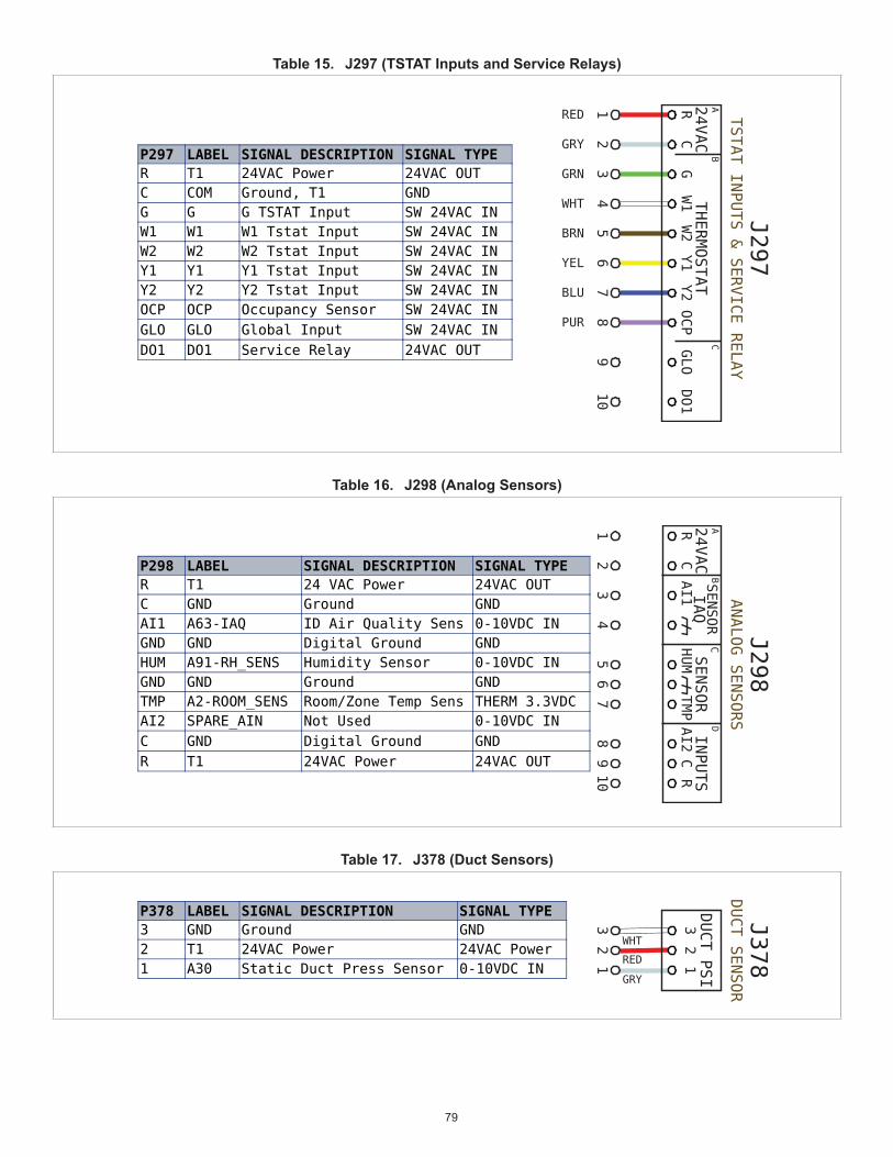
79
Table 15. J297 (TSTAT Inputs and Service Relays)
Table 16. J298 (Analog Sensors)
Table 17. J378 (Duct Sensors)

80
Table 18. J379 (Ultra Condenser)
Table 19. J380 (Smart Air)
Table 20. J381 (Indoor Blower and Outdoor Fan Variable Speed)
Table 21. J382 (All Evaporators)

81
Table 22. J383 (Ultra Evaporators)
Table 23. J384 (Economizer)
Table 24. J385 (All Condensers)
Table 25. J386 (Refrigerant Loss Detection)

82
Table 26. J387 (Options)
Table 27. J388 (Pressure Switches)
Table 28. J389 (Compressors 1 and 2)

83
Table 29. J390 (Relays)
Table 30. J391 (Compressor 2-Stage)
Table 31. J392 (Blower)
Table 32. J393 (Gas Heat)

84
Table 33. J393 (Electric Heat)
Table 34. J394 (ReHeat)
Table 35. J388 (C Box)
Table 36. J389 (C Box)

85
Table 37. J395 (Power In)
Table 38. J358 (MODUS Vs COMPR)
Table 39. J413 (Modbus)

86
16.2. C4 Control (A178)
Table 40. P396 (Electric Heat)
P396 CAV# LABEL DESCRIPTION TYPE8 GND Ground, HEAT4 GND4 HEAT4 Heat 4 24VAC OUT7 GND Ground, HEAT3 GND3 HEAT3 Heat 3 24VAC OUT6 EH_LIMIT Elec Ht Limit Sw Rtrn SW 24VAC2 EH_LIMIT Elec Ht Limit Sw 24VAC OUT5 24VAC_EXT 24 VAC Power 24VAC OUT1 GND Ground, 24VAC_EXT GND
42
13
56
78
12
34
56
78
WHT
GRY
GRY
RE D
BRN
WHT
GRY
WHTJ396
Table 41. P396 (Gas Heat)
J396
Table 42. P397 (Compressor Fans)
J397
Table 43. P398 (Compressors 3 and 4)
J398

87
Table 44. P399 (Pressure Switches 3 and 4)
J399
Table 45. P400 (24VAC)
J400
Table 46. P401 (All Evaporators)
J401
Table 47. P402 (Ultra Evaporators)
J402
Table 48. P403 (Options)
J403
Table 49. P404 (All Condensors)
J404

88
Table 50. P404 (Ultra Condensers)
J405
Table 51. P396 (Electric Heat)
P396 CAV# LABEL DESCRIPTION TYPE8 GND Ground, HEAT4 GND4 HEAT4 Heat 4 24VAC OUT7 GND Ground, HEAT3 GND3 HEAT3 Heat 3 24VAC OUT6 EH_LIMIT Elec Ht Limit Sw Rtrn SW 24VAC2 EH_LIMIT Elec Ht Limit Sw 24VAC OUT5 24VAC_EXT 24 VAC Power 24VAC OUT1 GND Ground, 24VAC_EXT GND
42
13
56
78
12
34
56
78
WHT
GRY
GRY
RE D
BRN
WHT
GRY
WHTJ396
Table 52. C4 Control Jacks and Plug Part Numbers
TE VAL - U- L OK TE RMI NAL PART # 794956- 1 ( S t r i p F or m) , Br a s s / Pr e- T i n, 18- 22AWG - L ennox Pa r t # 106505- 01
TE VAL - U- L OK BOARD HE ADE RS & CONNE CTI NG PL UG HOUS I NGS
# CIRCUITS BOARD HEADER DESIGNATION BOARD HEADER OEM PART # (TE) CONNECTING PLUG DESIGNATION LENNOX PART # CONNECTING PLUG OEM PART # (TE) COLOR8 J396 2029138-8 P396 106509-04 2029094-8 RED10 J397 1-2029142-0 P397 106510-05 1-2029100-0 BLUE4 J398 1586040-4 P398 106507-02 1969614-4 WHITE8 J399 2029142-8 P399 106510-04 2029100-8 BLUE2 J400 2029134-2 P400 106508-01 2029029-2 BLACK4 J401 2029138-4 P401 106509-02 2029094-4 RED4 J402 TBD P402 106504-03 2029208-4 BLACK6 J403 1586040-6 P403 106507-03 1969614-6 WHITE4 J404 2029142-4 P404 106510-02 2029100-4 BLUE4 J405 2029056-4 P405 106504-02 1586027-4 WHITE
16.3. DSI Board (A3)
Table 53. J406 (A3) (M4 Control))
J406
A3
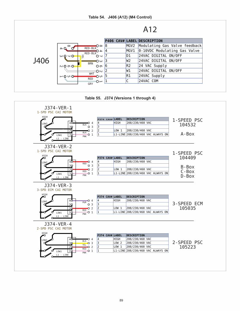
89
Table 54. J406 (A12) (M4 Control)
J406
A12
Table 55. J374 (Versions 1 through 4)

90
Table 56. J10 (GV1) (S18)
J10(S18)
Table 57. J408 (GV1) (S47)
J408
Table 58. J412 (MODUS 2)
Table 59. J411 (MODUS 1)

91
Table 60. J407 (S10 and S21)
J407
Table 61. DSI Control Jacks and Plugs Part Numbers
16.4. W4 Control
Table 62. W4 Control
W4 Board
BACnet
Wi-Fi Antenna Wi-Fi Antenna Bluetooth AntennaConnector 1 Connector 2 Connector
EthernetConnector 1
EthernetConnector 2
USB
M4 Connector(bottom side)
Bluetooth Switch
Con�g / Reset Switch
Wi-Fi Switch
Battery

92
17. Quick Start Guide
CAUTIONCheck rooftop unit electrical power for proper voltage and phasing. Check gas train components.
a. Turn on unit and dismiss alarm messages as necessary.b. FollowSETUP>INSTALLmenutoproperlyconfigureunitc. Be sure unit is in normal operating mode as seen in display (COOLING, HEATING, IDLE, etc).d. To verify operation use SERVICE > TEST menu.
Control Mode Menu Setup Needed TipsTHERMOSTAT (Factory set for 2-stage thermostat) Check LEDs for signals.
BACnet SETUP > NETWORK INTEGRATION > NETWORK WIZARD > NETWORK TYPE = BACNET MS/TP
• Setupinformationtobeverifiedwithintegrator.
• Follow wiring instructions including network termination
• Remember to set MAC address 0-127
• Expert level BACnet service manual available.
LonTalk SETUP > NETWORK INTEGRATION > NETWORK WIZARD > = LONTALK
• Setupinformationtobeverifiedwithintegrator.
• Follow wiring instructions including network termination
• XIFfileavailable.NeuronIDonsticker.
• Expert level LonTalk service manual available.
Damper SETUP > TEST & BALANCE > DAMPER • Verify damper minimum positions
• Refer to Economizer section of manual for more detail
Local Mode SETUP > NETWORK INTEGRATION > NETWORK WIZARD > RTU STANDALONE
• Give unit time to start-up.
• Humidity control requires sensor or error code 7649
Dehumidifier DehumidifiersetupwillbedoneduringtheSETUP>INSTALLwizard.It’sthelast part of that wizard.
• Three possible connections, LOCAL SENSOR, NETWORK SENSOR and REHEAT DI4.
• Analog sensor wiring is polarity sensitive
BlowerChange motor torque; see SETUP > TEST & BALANCE > BLOWER
• Final motor CFM should be set by Test and Balance technician
• Blower charts are located in the unit installation instruction.

93
18. Wiring Diagrams
02
03
04
05
06
07
08
09
10
01
AA BB CC EEDD FF
RED
7 8 9 2
WHT
1
RED
3 4 5 678 9 10
RED
BLU 1 2
1 2 31 2 3
3 4 21
1 2 3 6 2 6 7
PNK
GRY
WHTYE
L
YEL
YEL
YEL
YEL
RED
RED
BLK
BLK
RED
P255
P255
10
GRY
7x10CUTSIZE
Voltage: All Voltages
Model: LCM, LGM Series RTU
Supersedes: N/A Form No:
Thermostat
REV EC NO. DATE BY APVD REVISION NOTE--- CN-008594 10/15/2020 RV MXR6 ORIGINATED AT PD&R CARROLLTON, TX
Rev: 0
Y
R
B
Y
Y
15
Y
R
B
16 17 1 2
YEL
YEL
YEL
YEL
RED
RED
BLK
BLK
RED-
BLK
GRY
RED-
BLK
GRY
YEL
YEL
YEL
YEL
PNK
PNK
GRY
1
GRY
9 102 4 5 63 7 8 102 3 981 4 5 6 7
RED
4 3 6 1 2
1
P251 J251
1
J250 P250
2
3
4
2
3
4
1
P253 J253
2
3
4
1
J252 P252
2
3
4
1 8 7 2
WB-0
31
WB-0
30
B A
A55.
J297
A55.
J297
1
ORN
2
YEL
1
J261
2 3 4
YEL
YEL
PNK
GRY
1 2 3
1 2
RED
RED
6
C AI-1
GND
HUM
GND
AI-2
1, 5
A55.
J299
DI - 1 R
FI RE ALARM CONTACTSUPPLI ED BY OTHERS
C
P299J299
P387J387
R
J297P297
J298P298
A55.
J298
A55.
J298
A55.
J298
2
3
4
538078-01
Rev0
538078- 01
HEATING
SECTIONA
COOLING
SECTIONB
WIRING DIAGRAM FLOW
SECTIONB3
COOLING
SECTIONC
ACCS
SECTIOND
ACCS
CTRL SMOKEDETECT
A173
5
6
SENS
OR1
SENS
OR2
7 7
7
S52
ION
TEMP
R C G Y1 C Y1 Y2R C I AQ+
R C I AQ+
R I AQ+ I AQ- C
SUPERMARKET REHEAT
3 STAGE COOLI NG/3 STAGE HEATI NG
BACNET GATEWAY
GND
DENOTES OPTI ONAL COMPONENTSAND WI RI NG
GND
CLASS I I FI ELD WI RI NG
5
FREE
8
A55MAI N CTRL
GND
DI-1 R
9
R DI-4 C
FREE S2
7
C DI-2 R DI-3
TO PROVI DE SUPERMARKETREHEAT SCHEME USE S86DEHUMI DI STAT AND K55
C G W1
TOM4
THER
MOST
ATIN
PUT
Y1
FROM I AQWI RI NG DI AGRAM
OCP
GND
GLO
DO-1
Y2
P424
R
ALL OTHERTHERMOSTAT SI GNALSREMAI N CONNECTEDAS SHOWN ON THE TOP
TO PROVI DE THREECOMPRESSOR STAGES.REQUI RES 3 HEAT,3 COOL THERMOSTATAND K27 RELAY
J298 J297 J299
J387
A55
W2
24VA
C
4 5
S149
R
Figure 38. Wiring Diagram - Part 1

94

95
96
IndexAAbbreviations 37, 38Alarms 40
BBlower Operation with Effective Oc-
cupancy 30
CConnections 4, 7
DDamper Operation During Free Cool-
ing 32Demand Control Ventilation 35
EEconomizer Checkout 33Enabling Economizer and Settings 32Enthalpy Set Point 33
FFree Cooling Compressor Lockout
Mode 32Free Cooling Damper Maximum Posi-
tion 33
IICON Setting 75Inputs/Outputs 4
JJumpers 4
LL CONNECTION 37LED Operation Indicators 5LEDs 4Low Ambient Set Point 32
MMenu Selection Overview 9Minimum Damper Position 33MODBUS 4Motorized Outdoor Air Damper 33
OOutdoor Air Suitable for Free Cooling
33Overview 3
PParts and Kits 39Phase - Voltage Detection 40
QQuick Start Guide 92
SService Relays 40System Status Screen 7System Status Screen
Unit Operation 9
TThermal Protection Switches (S5, S7,
S8, S31 and S180) 29Thermostat / Humidistat Common
Isolation 4
UUnit Operation 9USB Flash Drive Interface Usage 4USB Service Report Example 39
WWiring Diagram 93