WaReS validation report - Marine Analytica
16
WaReS validation report [email protected] Marine Analytica https://marineanalytica.com Page 1 of 16 1 INTRODUCTION WaReS is a code developed by Marine Analytica to calculate wave-induced loads and responses in floating structures. This memo presents an extract of the verification report prepared for the future use of WaReS in commercial projects. Responses in irregular sea states and RAO are compared with the results published in [MA.1] for a typical 300 ft North Sea barge. The RAO and responses presented in [MA.1] have been calculated with the 3D diffraction package WADAM. WaReS results show good agreement over the range of wave frequencies analysed. 2 WARES DESCRIPTION WaReS stands for Wave Responses and are set of tools to perform hydrodynamic analysis in the linear frequency domain. The input for WaReS is a mesh describing the wet surface of the body, the mass and hydrostatic properties and the environmental data. The radiation and diffraction coefficients such as added mass, radiation damping and wave exciting loads are computed with the 3D radiation-diffraction code Nemoh. This code is an open source potential flow BEM solver developed at Ecole Centrale de Nantes see ref. [MA.2]. The motions of the floating body in regular waves are modelled as a linear mass-damping-spring system with frequency dependent coefficients and linear exciting wave forces/moments. ∑ [− 2 ( + ) + + ] 6 =1 = + The global RAO’s at the centre of rotation of the body are calculated by solving the equation of motion in the frequency domain for every degree of freedom. (, ) = ( + ) [− 2 ( + ) + + ] Assuming small responses and a rigid body, the transfer functions at any arbitrary point (P) are calculated as indicated in the equations below. The gravity horizontal components are incorporated in this analysis. (, ) = (, ) − (, ) + (, ) (,) = (,)+ (, ) − (, ) (,) = (, ) + (, ) − (, ) WaReS uses a potential non-viscous flow to calculate the hydrodynamic coefficients. For most of the DOF’s damping is predominantly linear and well captured by radiation- diffraction codes. However, in some cases like roll motions in mono-hulls the responses are dominated by viscous terms and therefore not well predicted by the potential flow. To consider non-linear damping in the linear frequency domain WaReS applies the stochastic linearization technique. This method considers the characteristics of an incoming wave spectrum and computes an equivalent amount of linear damping per sea-state. Multiple roll damping prediction methods are incorporated in WaReS Figure 1 and Figure 2 show the influence of the Hs, Tp and wave direction on the amount of roll damping applied to the 300ft barge. = 1 + √ 8 2 2 The floating body responses in irregular waves are calculated by combining the RAO’s with wave spectra for a set of wave directions, significant wave heights and wave periods. () = | ()| 2 ()
Transcript of WaReS validation report - Marine Analytica

WaReS validation report
Marine Analytica
https://marineanalytica.com
Page 1 of 16
1 INTRODUCTION
WaReS is a code developed by Marine Analytica to calculate wave-induced loads and responses in floating structures. This memo presents an extract of the verification report prepared for the future use of WaReS in commercial projects. Responses in irregular sea states and RAO are compared with the results published in [MA.1] for a typical 300 ft North Sea barge. The RAO and responses presented in [MA.1] have been calculated with the 3D diffraction package WADAM. WaReS results show good agreement over the range of wave frequencies analysed.
2 WARES DESCRIPTION
WaReS stands for Wave Responses and are set of tools to perform hydrodynamic analysis in the linear frequency domain. The input for WaReS is a mesh describing the wet surface of the body, the mass and hydrostatic properties and the environmental data. The radiation and diffraction coefficients such as added mass, radiation damping and wave exciting loads are computed with the 3D radiation-diffraction code Nemoh. This code is an open source potential flow BEM solver developed at Ecole Centrale de Nantes see ref. [MA.2]. The motions of the floating body in regular waves are modelled as a linear mass-damping-spring system with frequency dependent coefficients and linear exciting wave forces/moments.
∑ 𝑥𝑗[−𝜔2(𝑚𝑖𝑗 + 𝑎𝑖𝑗) + 𝑖𝜔𝑏𝑖𝑗 + 𝑐𝑖𝑗]
6
𝑗=1
= 𝐹𝑖𝐹𝐾 + 𝐹𝑖
𝐷
The global RAO’s at the centre of rotation of the body are calculated by solving the equation of motion in the frequency domain for every degree of freedom.
𝐻𝑗𝐺(𝜔, 𝜃) =
(𝐹𝑖𝐹𝐾 + 𝐹𝑖
𝐷)
[−𝜔2(𝑚𝑖𝑗 + 𝑎𝑖𝑗) + 𝑖𝜔𝑏𝑖𝑗 + 𝑐𝑖𝑗]
Assuming small responses and a rigid body, the transfer functions at any arbitrary point (P) are calculated as indicated in the equations below. The gravity horizontal components are incorporated in this analysis.
𝐻𝑋𝑃(𝜔, 𝜃) = 𝐻𝑋
𝐺(𝜔, 𝜃) − 𝑦𝑃 𝐻𝑅𝑍𝐺 (𝜔, 𝜃) + 𝑧𝑃 𝐻𝑅𝑌
𝐺 (𝜔, 𝜃)
𝐻𝑌𝑃(𝜔, 𝜃) = 𝐻𝑌
𝐺(𝜔, 𝜃) + 𝑥𝑃 𝐻𝑅𝑍𝐺 (𝜔, 𝜃) − 𝑧𝑃 𝐻𝑅𝑋
𝐺 (𝜔, 𝜃)
𝐻𝑍𝑃(𝜔, 𝜃) = 𝐻𝑍
𝐺(𝜔, 𝜃) + 𝑥𝑃 𝐻𝑅𝑌𝐺 (𝜔, 𝜃) − 𝑦𝑃 𝐻𝑅𝑋
𝐺 (𝜔, 𝜃) WaReS uses a potential non-viscous flow to calculate the hydrodynamic coefficients. For most of the DOF’s damping is predominantly linear and well captured by radiation- diffraction codes. However, in some cases like roll motions in mono-hulls the responses are dominated by viscous terms and therefore not well predicted by the potential flow. To consider non-linear damping in the linear frequency domain WaReS applies the stochastic linearization technique. This method considers the characteristics of an incoming wave spectrum and computes an equivalent amount of linear damping per sea-state. Multiple roll damping prediction methods are incorporated in WaReS Figure 1 and Figure 2 show the influence of the Hs, Tp and wave direction on the amount of roll damping applied to the 300ft barge.
𝑏𝑒𝑞 = 𝑏1 + √8
𝜋 2𝜋
𝑇𝑧𝜎𝑅𝑋 𝑏2
The floating body responses in irregular waves are calculated by combining the RAO’s with wave spectra for a set of wave directions, significant wave heights and wave periods.
𝑆𝑅(𝜔) = |𝐻𝑗𝑃(𝜔)|
2 𝑆𝑊(𝜔)

WaReS validation report
Marine Analytica
https://marineanalytica.com
Page 2 of 16
Figure 1 and Figure 2 show the impact of the wave height, period and direction on the amount of linearized roll damping applied to the system. As can be seen the largest amount of damping is obtained in beam seas for wave periods close to the barge roll natural period (T44 = 6.5 s). The linearized damping also increases with the design wave height (larger roll responses).
Figure 1 Linearized roll damping (% critical damping) vs wave direction and Tp
Figure 2 Linearized roll damping (% critical damping) vs Hs and Tp
The n-th spectral moments of the response spectrum are given by:
𝑚𝑛,𝑟(𝜔) = ∫ 𝜔𝑛∞
0
𝑆𝑅(𝜔)𝑑𝜔
For comparison purposes the responses presented in this report are 3h single amplitudes Most Probable Maximum (MPM). This correspond to a return period of 1/N, where N are the number of oscillations during the considered period (3 hours).
𝜎2 = 𝑚0 = ∫ 𝑆𝑅(𝜔)𝑑𝜔∞
0
𝑈𝑀𝑃𝑀 = 𝜎√2 ln (𝑁)

WaReS validation report
Marine Analytica
https://marineanalytica.com
Page 3 of 16
2.1 Reference documents
Guidelines and standards
[GS1] DNVGL-RP-C205 Recommended practice for environmental conditions and environmental loads
Reference documents
[MA.1] Barge Transportation of Heavy Objects – Norwegian Technology University – June 2010
[MA.2] Theoretical and numerical aspects of the open source BEM solver NEMOH - A. Babarit, G.
Delhommeau.
2.2 Abbreviations
APP Aft perpendicular
Aij Added mass/inertia
Bij Radiation damping
B1 Linear damping
B2 Quadratic damping
Bcrit Critical damping
BEM Boundary element methods
BL Base line
Cij Hydrostatic stiffness
CL Centre line
deg degree
ft fee/foot
FFK Froude-Krilov wave loads
FD Diffraction wave loads
g gravity
Gmlong Longitudinal metacentric height
GMtran Transverse metacentric height
Hs Significant wave height
JONSWAP Joint North Sea Wave Project
kii Radius of gyration
kg kilogram
LCG/LCB Longitudinal Centre of Gravity/Buoyancy
λ Wavelength
m meter
m0 Zero spectral moment
Mij Mass/inertia
MPM Most Probable Maximum
N Number of oscillations
RAO Response Amplitude Operator, also presented as H (ω,θ)
σ Standard deviation
σRX Standard deviation of the roll velocity
s second
𝑆𝑅(𝜔) Response spectrum
𝑆𝑤(𝜔) Wave spectrum
TCG/TCB Transverse Centre of Gravity/Buoyancy
Tp Wave peak period
Tz Zero-up crossing period
VCG/VCB Vertical Centre of Gravity/Buoyancy
ω wave frequency

WaReS validation report
Marine Analytica
https://marineanalytica.com
Page 4 of 16
2.3 Barge reference system
The global coordinate system of the barge is defined as follows, see Figure 3.
• X-axis (from APP) in longitudinal vessel direction pointing forward
• Y-axis (from CL) in transverse vessel direction pointing portside
• Z-axis (from BL) in vertical direction pointing upwards
Figure 3 Barge coordinate system
3 ANALYSIS DESCRIPTION
The verification is performed for a free floating 300ft North Sea barge with a module on 1000mT on deck as
described in [MA.1]. The main particulars of the barge and the loading condition are presented in Table 2. All the
dimensions are measured from the barge reference system described in Figure 3.
Figure 4 WaReS 300ft North Sea barge hull mesh
The maximum panel size has been defined based on the shortest wavelength to comply with the λ/7 rule. In this
case the maximum mesh size is 2.5 m suitable for wave frequencies between 0.2 rad/s and 1.85 rad/s. A total of
166 wave frequencies have been computed in steps of 0.01 rad/s. The diffraction/radiation analysis has been
performed with the following parameters:
Table 1 Radiation-diffraction analysis particulars
Description Units Quantity
Water depth [m] 300.0
Water density [kg/m3] 1025.0
Gravity [m/s2] 9.81

WaReS validation report
Marine Analytica
https://marineanalytica.com
Page 5 of 16
Table 2 300ft barge main particulars
Description Units Quantity Description Units Quantity
Lpp [m] 91.40 LCF [m] 45.25
B [m] 27.40 TCF [m] 0
D [m] 6.00 LCB [m] 45.23
T [m] 2.78 TCB [m] 0
Tfwd [m] 2.49 VCB [m] 1.39
Taft [m] 3.07 GMtransv [m] 20.7
Δ [ton] 6263.00 GMlongit [m] 236.86
CB [-] 0.88 kMtransv [m] 25.68
LCG [m] 44.24 kMlongit [m] 241.84
TCG [m] 0.00 kxx [m] 10.63
VCG [m] 4.98 kyy [m] 28.47
Awl [m2] 2367.00 kzz [m] 29.49
The sea-states presented in Table 3 have been analysed.
Table 3 Design sea-states
Seastate Hs [m] Tp min [s] Tp max [s]
A 2.0 4.0 20.0
B 3.0 4.0 20.0
C 3.5 4.0 20.0
The wave energy is modelled by a JONSWAP spectrum with varying peak factor γ as function of the significant wave height and period as described in [GS1]. No wave spreading is considered in the analysis.
𝑆𝐽(𝜔) = 𝐴𝛾 𝑆𝑃𝑀(𝜔) 𝛾 𝑒(−0.5(
𝜔−𝜔𝑝
𝜎𝜔𝑝)
2)
The barge responses have been determined at the local points shown in Table 4 measured from the barge
reference system described in Figure 3.
Table 4 Barge local points analysed
Location P1 P2 P3 P4 P5
X [m] 42.72 27.72 57.72 27.72 57.72
Y [m] 0.00 6.00 6.00 6.00 6.00
Z [m] 14.60 7.50 7.50 21.50 21.50
WaReS validation report
Marine Analytica
https://marineanalytica.com
Page 6 of 16
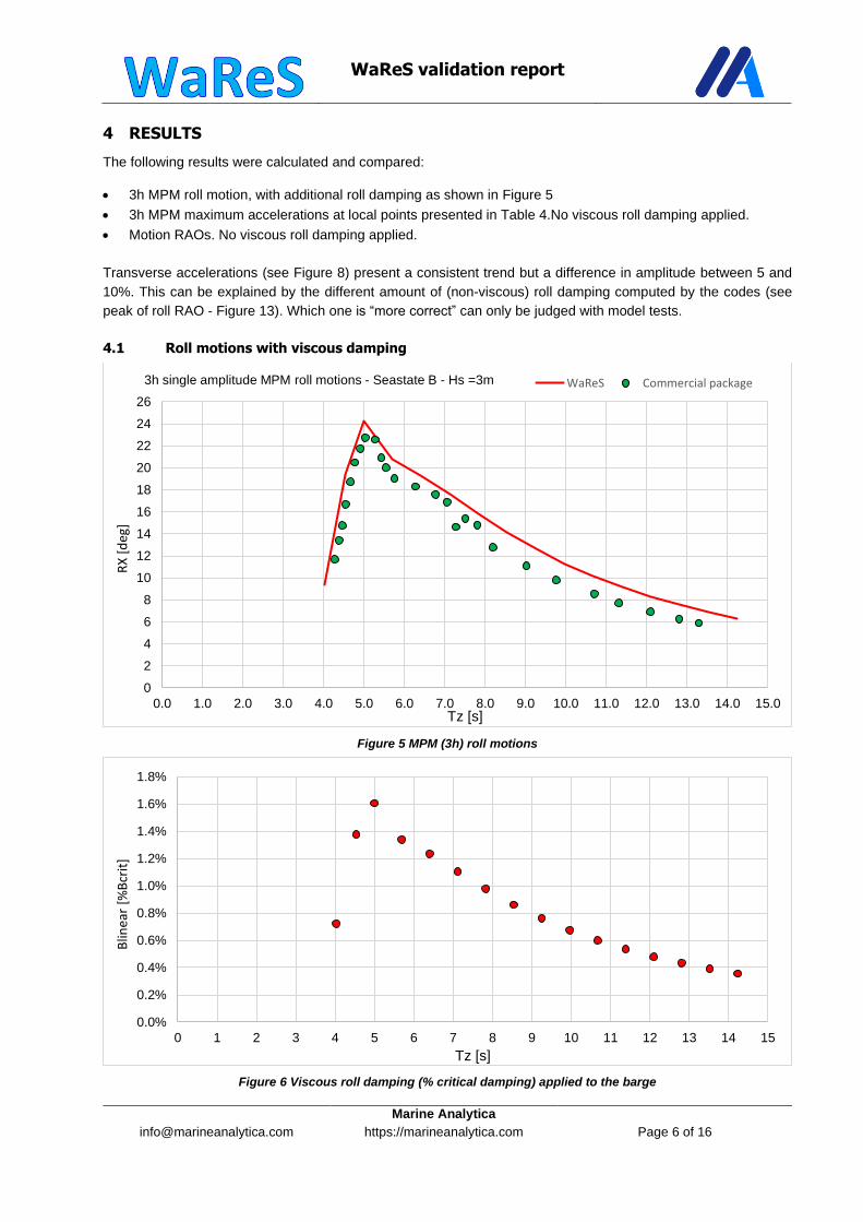
4 RESULTS
The following results were calculated and compared:
• 3h MPM roll motion, with additional roll damping as shown in Figure 5
• 3h MPM maximum accelerations at local points presented in Table 4.No viscous roll damping applied.
• Motion RAOs. No viscous roll damping applied.
Transverse accelerations (see Figure 8) present a consistent trend but a difference in amplitude between 5 and
10%. This can be explained by the different amount of (non-viscous) roll damping computed by the codes (see
peak of roll RAO - Figure 13). Which one is “more correct” can only be judged with model tests.
4.1 Roll motions with viscous damping
Figure 5 MPM (3h) roll motions
Figure 6 Viscous roll damping (% critical damping) applied to the barge
0
2
4
6
8
10
12
14
16
18
20
22
24
26
0.0 1.0 2.0 3.0 4.0 5.0 6.0 7.0 8.0 9.0 10.0 11.0 12.0 13.0 14.0 15.0
RX
[d
eg]
Tz [s]
3h single amplitude MPM roll motions - Seastate B - Hs =3m WaReS Commercial package
0.0%
0.2%
0.4%
0.6%
0.8%
1.0%
1.2%
1.4%
1.6%
1.8%
0 1 2 3 4 5 6 7 8 9 10 11 12 13 14 15
Blin
ear
[%B
crit
]
Tz [s]

WaReS validation report
Marine Analytica
https://marineanalytica.com
Page 7 of 16
4.2 Maximum accelerations without viscous damping
Figure 7 Longitudinal accelerations + gravity component (3h MPM)
Figure 8 Transverse accelerations + gravity component (3h MPM)
Figure 9 Vertical accelerations without gravity (3h MPM)
0.59
0.38 0.38
0.92 0.92
0.55
0.35 0.35
0.91 0.91
0
0.2
0.4
0.6
0.8
1
P1 P2 P3 P4 P5
AX
[m
/s2
]
Local point
Longitudinal accelerations - Seastate A Commercial package WaReS
5.85
3.96 3.91
7.79 7.75
5.32
3.48 3.53
7.29 7.37
0
2
4
6
8
10
P1 P2 P3 P4 P5
AY
[m
/s2
]
Local point
Transverse accelerations - Seastate A Commercial package WaReS
1.22
2.65 2.65 2.65 2.65
1.20
2.50 2.56 2.50 2.56
0
0.5
1
1.5
2
2.5
3
P1 P2 P3 P4 P5
AZ
[m
/s2
]
Local point
Vertical accelerations - Seastate A Commercial package WaReS

WaReS validation report
Marine Analytica
https://marineanalytica.com
Page 8 of 16
4.3 Global motion RAO without viscous damping
Figure 10 Global surge motion RAO
0.0
0.2
0.4
0.6
0.8
1.0
1.2
0.0 0.2 0.4 0.6 0.8 1.0 1.2 1.4 1.6 1.8 2.0 2.2 2.4
X/ξ
[m/m
]
wave frequency [rad/s]
surge motion RAO - dir = 0 deg Commercial package WaReS
0.0
0.1
0.2
0.3
0.4
0.5
0.6
0.7
0.8
0.9
1.0
0.0 0.2 0.4 0.6 0.8 1.0 1.2 1.4 1.6 1.8 2.0 2.2 2.4
X/ξ
[m/m
]
wave frequency [rad/s]
surge motion RAO - dir = 30 deg Commercial package WaReS
0.0
0.1
0.2
0.3
0.4
0.5
0.6
0.0 0.2 0.4 0.6 0.8 1.0 1.2 1.4 1.6 1.8 2.0 2.2 2.4
X/ξ
[m/m
]
wave frequency [rad/s]
surge motion RAO - dir = 60 deg Commercial package WaReS
WaReS validation report
Marine Analytica
https://marineanalytica.com
Page 9 of 16
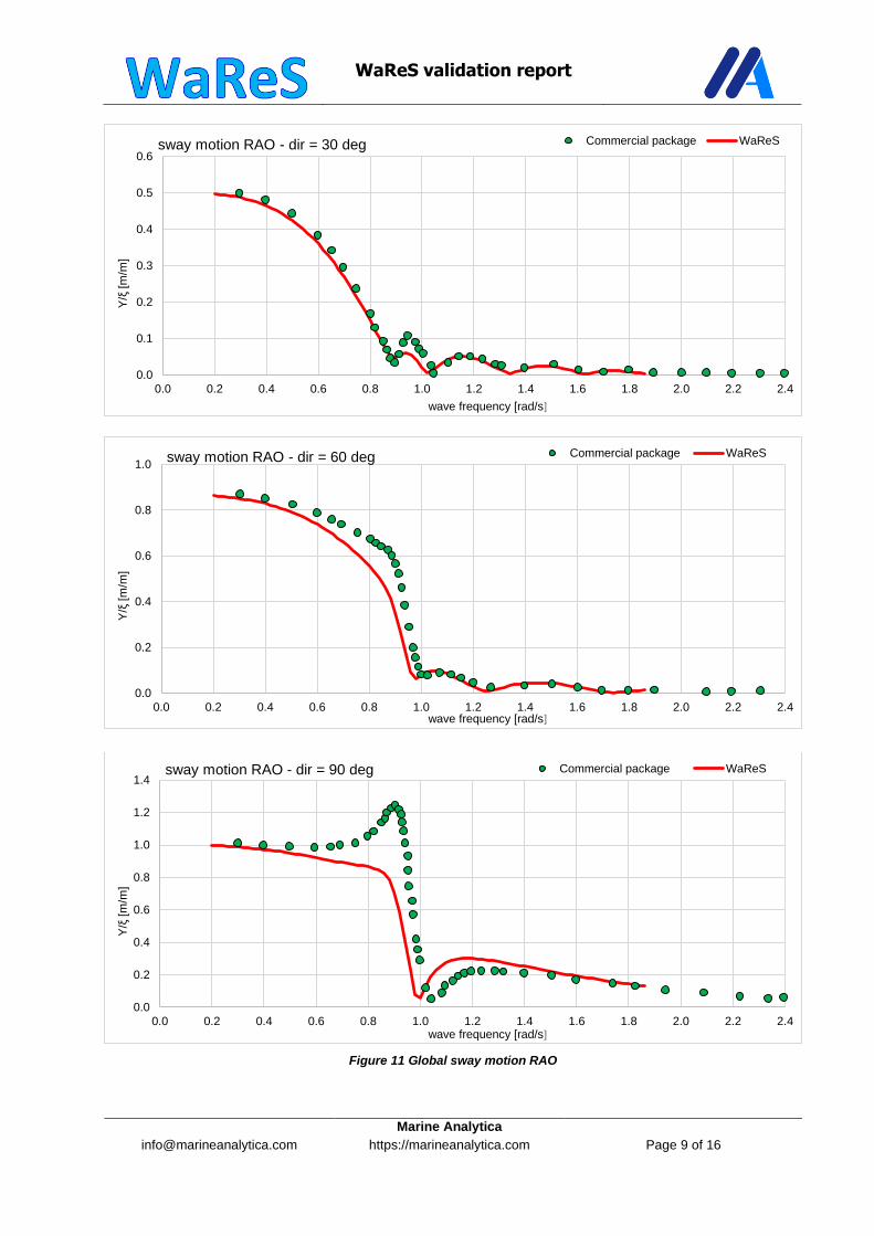
Figure 11 Global sway motion RAO
0.0
0.1
0.2
0.3
0.4
0.5
0.6
0.0 0.2 0.4 0.6 0.8 1.0 1.2 1.4 1.6 1.8 2.0 2.2 2.4
Y/ξ
[m/m
]
wave frequency [rad/s]
sway motion RAO - dir = 30 deg Commercial package WaReS
0.0
0.2
0.4
0.6
0.8
1.0
0.0 0.2 0.4 0.6 0.8 1.0 1.2 1.4 1.6 1.8 2.0 2.2 2.4
Y/ξ
[m/m
]
wave frequency [rad/s]
sway motion RAO - dir = 60 deg Commercial package WaReS
0.0
0.2
0.4
0.6
0.8
1.0
1.2
1.4
0.0 0.2 0.4 0.6 0.8 1.0 1.2 1.4 1.6 1.8 2.0 2.2 2.4
Y/ξ
[m/m
]
wave frequency [rad/s]
sway motion RAO - dir = 90 deg Commercial package WaReS

WaReS validation report
Marine Analytica
https://marineanalytica.com
Page 10 of 16
Figure 12 Global heave motion RAO
0.0
0.2
0.4
0.6
0.8
1.0
1.2
0.0 0.2 0.4 0.6 0.8 1.0 1.2 1.4 1.6 1.8 2.0 2.2 2.4
Z/ξ
[m/m
]
wave frequency [rad/s]
heave motion RAO - dir = 0 deg Commercial package WaReS
0.0
0.2
0.4
0.6
0.8
1.0
1.2
0.0 0.2 0.4 0.6 0.8 1.0 1.2 1.4 1.6 1.8 2.0 2.2 2.4
Z/ξ
[m/m
]
wave frequency [rad/s]
heave motion RAO - dir = 60 deg Commercial package WaReS
0.0
0.2
0.4
0.6
0.8
1.0
1.2
0.0 0.2 0.4 0.6 0.8 1.0 1.2 1.4 1.6 1.8 2.0 2.2 2.4
Z/ξ
[m/m
]
wave frequency [rad/s]
heave motion RAO - dir = 90 deg Commercial package WaReS

WaReS validation report
Marine Analytica
https://marineanalytica.com
Page 11 of 16
Figure 13 Global roll motion RAO (only radiation damping)
0.0
0.2
0.4
0.6
0.8
1.0
1.2
1.4
1.6
1.8
0.0 0.2 0.4 0.6 0.8 1.0 1.2 1.4 1.6 1.8 2.0 2.2 2.4
RX
/ξ[d
eg/m
]
wave frequency [rad/s]
roll motion RAO - dir = 30 deg Commercial package WaReS
0.0
1.0
2.0
3.0
4.0
5.0
6.0
7.0
0.0 0.2 0.4 0.6 0.8 1.0 1.2 1.4 1.6 1.8 2.0 2.2 2.4
RX
/ξ[d
eg/m
]
wave frequency [rad/s]
roll motion RAO - dir = 60 deg Commercial package WaReS
0.0
2.0
4.0
6.0
8.0
10.0
12.0
14.0
16.0
18.0
20.0
0.0 0.2 0.4 0.6 0.8 1.0 1.2 1.4 1.6 1.8 2.0 2.2 2.4
RX
/ξ[d
eg/m
]
wave frequency [rad/s]
roll motion RAO - dir = 90 deg Commercial package WaReS

WaReS validation report
Marine Analytica
https://marineanalytica.com
Page 12 of 16
Figure 14 Global pitch motion RAO
0.0
0.3
0.6
0.9
1.2
1.5
1.8
2.1
2.4
0.0 0.2 0.4 0.6 0.8 1.0 1.2 1.4 1.6 1.8 2.0 2.2 2.4
RY
/ξ[d
eg/m
]
wave frequency [rad/s]
pitch motion RAO - dir = 0 deg Commercial package WaReS
0.0
0.2
0.4
0.6
0.8
1.0
1.2
1.4
1.6
1.8
2.0
0.0 0.2 0.4 0.6 0.8 1.0 1.2 1.4 1.6 1.8 2.0 2.2 2.4
RY
/ξ[d
eg/m
]
wave frequency [rad/s]
pitch motion RAO - dir = 60 deg Commercial package WaReS
0.00
0.50
1.00
1.50
2.00
2.50
0.0 0.2 0.4 0.6 0.8 1.0 1.2 1.4 1.6 1.8 2.0 2.2 2.4
RY
/ξ[d
eg/m
]
wave frequency [rad/s]
pitch motion RAO - dir = 150 deg Commercial package WaReS

WaReS validation report
Marine Analytica
https://marineanalytica.com
Page 13 of 16
Figure 15 Global yaw motion RAO
0.0
0.1
0.2
0.3
0.4
0.5
0.0 0.2 0.4 0.6 0.8 1.0 1.2 1.4 1.6 1.8 2.0 2.2 2.4
RZ
/ξ[d
eg/m
]
wave frequency [rad/s]
yaw motion RAO - dir = 30 deg Commercial package WaReS
0.0
0.1
0.2
0.3
0.4
0.5
0.6
0.0 0.2 0.4 0.6 0.8 1.0 1.2 1.4 1.6 1.8 2.0 2.2 2.4
RZ
/ξ[d
eg/m
]
wave frequency [rad/s]
yaw motion RAO - dir = 60 deg Commercial package WaReS
0.00
0.10
0.20
0.30
0.40
0.50
0.60
0.70
0.0 0.2 0.4 0.6 0.8 1.0 1.2 1.4 1.6 1.8 2.0 2.2 2.4
RZ
/ξ[d
eg/m
]
wave frequency [rad/s]
yaw motion RAO - dir = 120 deg Commercial package WaReS

WaReS validation report
Marine Analytica
https://marineanalytica.com
Page 14 of 16
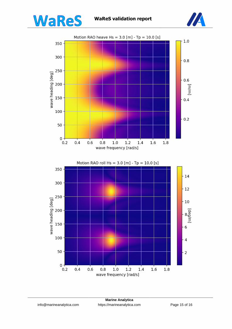
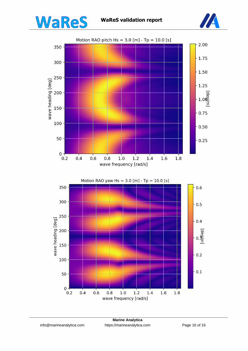
5 WARES GLOBAL RAO 2D
WaReS validation report
Marine Analytica
https://marineanalytica.com
Page 15 of 16
WaReS validation report
Marine Analytica
https://marineanalytica.com
Page 16 of 16