WALL CONTROLLER USER GUIDE
51
WALL CONTROLLER USER GUIDE Version 1.0.0 600
Transcript of WALL CONTROLLER USER GUIDE

WALL CONTROLLER USER GUIDE
Version 1.0.0
600

Contents2
Table of Contents
Disclaimer/Copyright Statement.............................................................5
Quick Start Guide...................................................................................6
Contents.................................................................................................................6
Step 1 - Keyboard and Mouse....................................................................................6
Step 2 - Connect to a Network (Optional)...................................................................7
Step 3 - Connect Input Source....................................................................................7
Step 4 - Connect Control Screen (Optional) and Monitors.............................................8
Step 5 - Powering up the System...............................................................................9
Step 6 - Windows®7 Setup.......................................................................................10
Step 7 - Activate Windows®7...................................................................................10
Step 8 - Display Setup.............................................................................................11
Step 9 - WallControl 10 (Optional)............................................................................12
Chapter 1 - Introduction........................................................................14
1.1 Introduction.....................................................................................................14
1.2 Systems ..........................................................................................................14
1.3 How the User Guide is Organised.......................................................................14
1.4 Fonts and Symbols...........................................................................................14
1.5 Terminology and Definitions..............................................................................15
Chapter 2 - Safety.................................................................................16
2.1 Safety Precautions...........................................................................................16
2.2 Unpacking and Initial Inspection.........................................................................17
Chapter 3 - General...............................................................................18
3.1 Overview..........................................................................................................18
3.2 Associated Output/Input Cards and Related Products..........................................18
3.3 Product Datasheets..........................................................................................18
Chapter 4 - Hardware............................................................................19
4.1 VSNMicro 600..................................................................................................19
4.2 Power Supply Modules (RPSU System)...............................................................20

Contents
Contents3
Chapter 5 - Cabling................................................................................21
5.1 Connecting the Keyboard and Mouse..................................................................21
5.2 Connecting to a Network (Optional)...................................................................21
5.3 Connecting Input Sources..................................................................................22
5.4 Connect Monitors and Control Screen (Optional).................................................22
5.5 Connecting Power Cables..................................................................................24
Chapter 6 - Operation...........................................................................25
6.1 Switching On....................................................................................................25
6.2 Initial System Boot on Delivery..........................................................................25
6.3 Opening WallControl 10 (Optional).....................................................................27
6.4 Opening Wall Control (Optional).........................................................................28
6.5 Displaying Video Captures.................................................................................29
Chapter 7 - Software.............................................................................31
7.1 WallControl 10 (Optional)..................................................................................31
7.2 WallControl 10 - Features and Tools....................................................................31
7.3 Wall Control (Optional)......................................................................................32
7.4 Wall Monitor (Optional).....................................................................................35
7.5 Vision Application (Optional).............................................................................37
7.6 Software Utilities..............................................................................................39
Chapter 8 - Technical Support................................................................40
8.1 Technical Support ............................................................................................40
Chapter 9 - Maintenance.......................................................................41
9.1 Filter Maintenance...........................................................................................41
Chapter 10 - Environmental ..................................................................42
10.1 Certification and Compliances..........................................................................42
Contents
Contents4
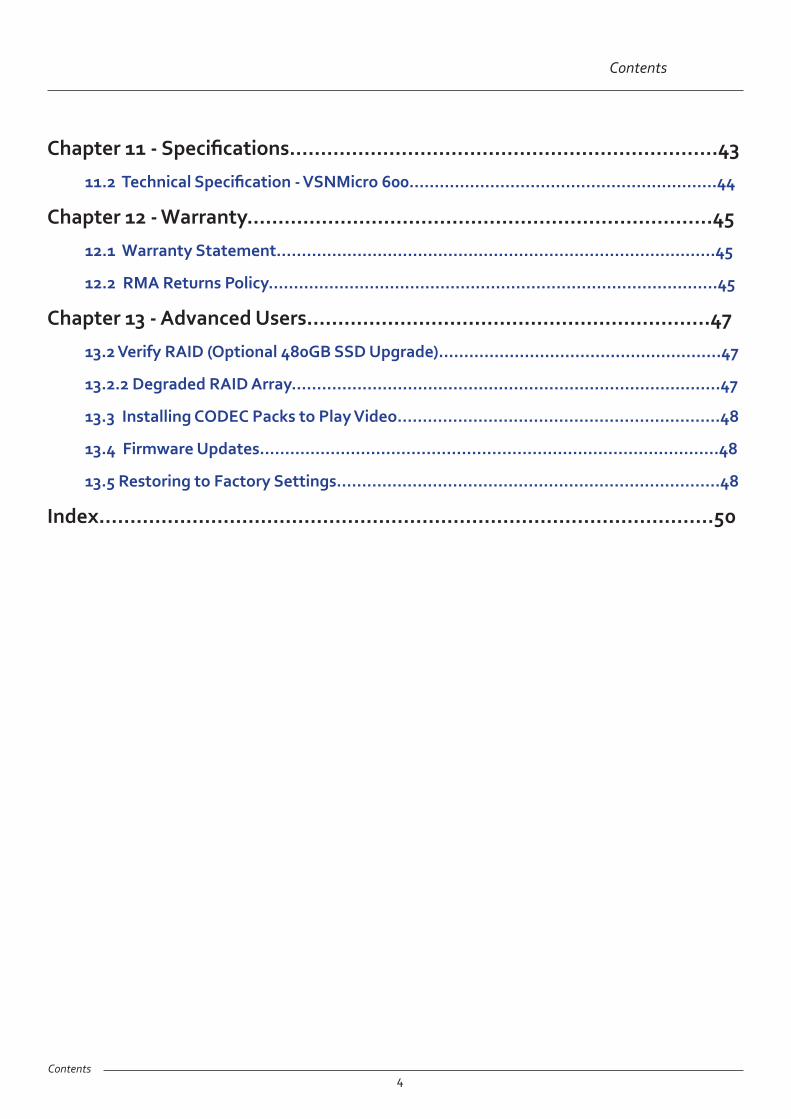
Chapter 11 - Specifications.....................................................................43
11.2 Technical Specification - VSNMicro 600.............................................................44
Chapter 12 - Warranty...........................................................................45
12.1 Warranty Statement.......................................................................................45
12.2 RMA Returns Policy.........................................................................................45
Chapter 13 - Advanced Users.................................................................47
13.2 Verify RAID (Optional 480GB SSD Upgrade)........................................................47
13.2.2 Degraded RAID Array.....................................................................................47
13.3 Installing CODEC Packs to Play Video................................................................48
13.4 Firmware Updates...........................................................................................48
13.5 Restoring to Factory Settings............................................................................48
Index...................................................................................................50

Copyright Statement
Disclaimer/Copyright Statement
© Datapath Ltd, England 2016
Datapath Limited claims copyright on this User Guide. No part of this User Guide may be reproduced, released, disclosed, stored in any electronic format, or used in whole or in part for any purpose other than stated herein without the express permission of Datapath Limited.
Whilst every effort is made to ensure that the information contained in this User Guide is correct, Datapath Limited make no representations or warranties with respect to the contents thereof, and do not accept liability for any errors or omissions.
Datapath reserves the right to change specification without prior notice and cannot assume responsibility for the use made of the information supplied. Datapath Limited acknowledges all registered trademarks used within this User Guide.
5

Quick Start Guide
Quick Start Guide
6
Main SystemVSNMicro 600 systemPower Supply Modules (RPSU only)Mouse/KeyboardRecovery MediaCables/Adapters Accessories Pack PCIe card product leafletsBuild LogMAC Address Labels
Contents
A version of the Quick Start Guide is included below for your convenience.
Step 1 - Keyboard and Mouse
Each Datapath VSNMicro 600 is custom built to order therefore the components, number and type of input and output cards will differ from system to system.
Contained within the documentation pack are PCIe card product leaflets which give details on how the cards are installed and any accessories which may accompany them.
Connect Keyboard and Mouse to USB Ports.

Quick Start Guide
Quick Start Guide7
Step 2 - Connect to a Network (Optional)
Step 3 - Connect Input Source
Input Connectors
As each system is custom built, the number and type of inputs will differ from system to system. Contained within the documentation pack is a Build Log detailing the PCIe cards installed and where they are located on the backplane. The enclosed Product leaflets give details on how the cards are connected.

Quick Start Guide8
Quick Start Guide
Step 4 - Connect Control Screen (Optional) and Monitors
14
Monitor 2Monitor 3Monitor 4
Monitor 5
Monitor 7Monitor 6
Monitor 8
Monitor 1
Connect graphic outputs to monitors using DisplayPort cables.
(Not supplied)
Control Screen (Optional)
4 x 2 Video Wall
1 3 4
5 6 7 82
Many of our wall controllers are configured to use a control screen (Internal Graphics Device) prior to leaving the factory. If required, connect the control screen to the motherboard as shown above. If a control screen is not required, the BIOS settings will require changing. For instructions consult the system User Guide which can be found on the Recovery Media.

Quick Start Guide
Quick Start Guide9
Step 5 - Powering up the System
Connect power cables (single cable for ATX) then plug into and turn on the mains supply.
Switch on the system.
1
3
If you have an ATX powered system, go straight to step 2 below.
For systems with an RPSU:
During transit, the Power Supply Modules are removed therefore you are required to fit them prior to using your VSNMicro 600. To fit the Power Supply Modules, remove the all packaging and carefully slide them into the power supply unit on the rear of the system with the protective grill uppermost. You will feel and hear a firm click when they are in place. For detailed instructions on how to fit the Power Supply Modules see the system User Guide which can be found on the Recovery Media.
Never use force when inserting the Power Supply Modules as this can cause damage not covered under the Datapath warranty.
2
Ensure Power Supply Modules are correctly fitted.

Quick Start Guide
Quick Start Guide10
Computer Name:
It is recommended that only Internet-standard characters are used in the computer name. The standard characters are the numbers 0 through to 9, upper and lower-case letters from A through to Z and the hyphen character. Computer names cannot consist entirely of numbers, contain spaces or use special characters such as: < > ; : “ ?* + = \ | ? ,.
Step 6 - Windows®7 Setup
Start | Computer | Properties | Activate Windows now.
Step 7 - Activate Windows®7
The Product key is lo-cated behind the front
panel. Gently pull away the front panel
for access.
Select the appropriate method available.
To view the product key, gently pull away the front panel of the VSNMicro 600. The front panel is held in place using a series of magnetic points.

Quick Start Guide
Quick Start Guide11
All Datapath wall controllers have pre-configured settings for the wall layout and screen resolution. Change settings using the TWIN tab:
Start | Control Panel | Appearance and Personalization | Adjust screen resolution.
1
2
3
Step 8 - Display Setup
Start | All Programs | WallControl 10 - Client
Quick Start Guide
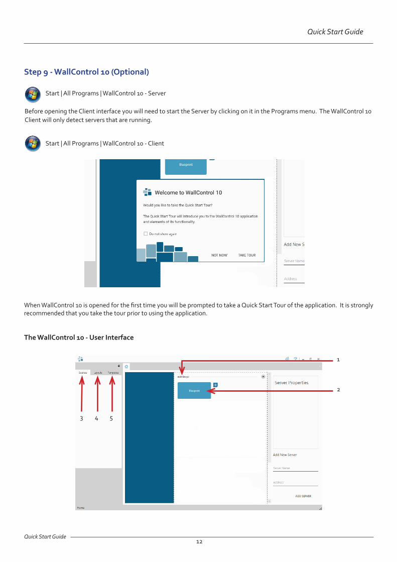
Step 9 - WallControl 10 (Optional)
Quick Start Guide12
When WallControl 10 is opened for the first time you will be prompted to take a Quick Start Tour of the application. It is strongly recommended that you take the tour prior to using the application.
The WallControl 10 - User Interface
1
2
3 4 5
Start | All Programs | WallControl 10 - Server
Before opening the Client interface you will need to start the Server by clicking on it in the Programs menu. The WallControl 10 Client will only detect servers that are running.

1 Indicates the server you are connected too.
2 A representation of the display wall associated with the server.
3 Sources Tab - Displaying all the sources connected to the server for use on the your display wall.
4 Layouts Tab - Used to save, recall and share display wall layout configurations.
5 Templates Tab - Use templates to assist in the design of specific display wall layouts.
Quick Start Guide
When opened, the display wall tab shows a live representation of the physical wall and the sources available to display on it. To place a source on the video wall, simply click on the required source in the sources tab and drag it onto the display wall representation.
The application help file contains videos explaining how multiple sources can be selected, how to use and create templates and how to save, recall and share layout files.
Note:If you have Wall Control-red installed, please refer to the system User Guide which can be found on the Recovery Media.
Quick Start Guide13
Display Wall Tab
Sources
Click on the display wall representation to open the display wall tab.
Display Wall Representation

Introduction
Chapter 1 - Introduction
1.1 Introduction
Congratulations on your purchase of the Datapath VSNMicro 600. The wall controller has been manufactured and tested to the highest standards offering unparalleled quality and reliability. The aim of this user guide is to assist you through the installation of the system safely and effectively and act as a reference guide for future use. Do not switch on the system until all the relevant cables have been connected.
1.2 Systems
The system covered by this user guide is the VSNMicro 600 display wall controller.
1.3 How the User Guide is Organised
The user guide is broken down into chapters and each chapter into sections. Chapters, sections and pages are numbered individually. Pages are numbered in Arabic numerals with the exception of the cover page (no numbering).
1.4 Fonts and Symbols
1.4.1 Fonts
The font used throughout the user guide is Corbel however the following font styles mean:
Bold = Used to describe menu titles, buttons in software or elements that you must type exactly as shown in the Command Line Interface
Ellipsis (...) - Parameter that can be repeated several times in a command line.
Between brackets ([]) - Optional items.
Between braces ({}) - Set of choices (separated by I) from which you must choose only one.
Italic = Information that must be supplied by the user
Courier = Indicates code or program output.
Blue Underlined = Indicates a hyper-link. Some hyper-links may be linked to external live websites.
1.4.2 Symbols
Symbols are used throughout this user guide to assist the user in quickly identifying important safety information and notes.
Yellow triangle indicates that failure to observe the instructions could result in injury and/or damage to the system.
Lifting precautions should be considered.
White arrow in a blue box indicates a useful tip.
White exclamation mark in a blue box indicates important information.
14

Introduction
1.5 Terminology and Definitions
1.5.1 BIOS
Basic Input/Output System: Used during system boot up to initialise and test system hardware and load the operating system. Each BIOS is specifically designed to work with a particular motherboard.
1.5.2 Control Screen
Some systems are shipped with the BIOS configured to boot the system off the onboard graphics device. This output can then be used as the Control Screen for a typical video wall. The content of the control screen is not displayed on the video wall desktop and can be used to host the Wall Control application window.
1.5.3 SDK
Software Development Kit: A set of software development tools which allows the creation of certain applications
1.5.4 WallControl 10 (Optional)
WallControl 10 provides users with the interface required to quickly and effectively manage content that include video captures, IP streams and local applications. Users are able to place any input source on any part of the Video Wall using a simple drag and drop operation. Precise positioning of each piece of content can be achieved through the mouse and keyboard, or via the revolutionary template tool.
1.5.5 Wall Control-red (Optional)
An optional software application for controlling and managing Vision, IP-Camera and third party application windows on a Datapath Wall Controller. Providing a graphical representation of the video wall and a toolbar through which to manipulate all available input sources and applications. Can also be used offline.
1.5.6 Wall Monitor (Optional)
A software application that enables the user to monitor the temperatures and voltages of system components.
1.5.7 Screen Order
The order in which the screens appear on the display wall.
1.5.8 SQX
SQX is Datapath’s collective name for its video streaming and compression technologies.
15Introduction

Safety
Chapter 2 - Safety
16
2.1 Safety Precautions
To prevent damage to your Datapath product or injury to personnel operating the equipment, please read the following safety precautions prior to operation. These instructions should be made available to all those who will use and operate Datapath products.
2.1.1 Power Supply
All Datapath products require a mains power supply. This power supply must be disconnected when equipment is being upgraded or relocated.
2.1.2 Cables
Do not expose cables to any liquids; doing so may cause a short circuit which could damage the equipment. Do not place heavy objects on top of any cables as this can cause damage and possibly lead to exposed live wires.
2.1.3 Ventilation
All computer equipment should be located in a well ventilated area. All ventilation holes on the computer casing must be kept clear of any obstruction at all times. Failure to do so will result in the system over heating and damaging your equipment.
2.1.4 Working Environment
The equipment should be located in an environment free from dust, moisture and extreme changes in temperature and should be placed on a stable and solid work surface. Liquids (hot/cold drinks etc) should not be placed near the equipment as spillage could cause serious damage.
2.1.5 Gas/Flammable Liquids
Electronic equipment should never be used in the presence of gas or any flammable liquid, doing so could result in an explosion or serious fire.
2.1.6 Smoke/Unusual Smells
Should you notice smoke or unusual smells being emitted from your system, turn off and unplug the system from the mains supply. The system should then be passed to a qualified technician for inspection. Continued operation could result in personal injury and damage to property.
2.1.7 Maintenance
Apart from what is detailed in this user guide, maintenance should only be carried out by competent technicians, any Datapath plug-in cards that are physically damaged should be returned to Datapath for repair using Datapath RMA procedures.
2.1.8 Replaceable Batteries
Caution: Risk of explosion if batteries are replaced by an incorrect type. Dispose of used batteries according to the local laws / regulations and manufacturer’s instructions.

Safety17
Safety
2.2 Unpacking and Initial Inspection
To unpack the system follow the instructions provided on the outside of the packaging. All packaging materials should be retained for future transit.
2.3.1 Initial Inspection
All systems are carefully prepared for shipment and every effort is made to ensure you receive the product in pristine condition. On receipt, you should carefully inspect the outer packaging for any transit damage i.e. any signs that the system may have been dropped etc.
Use the packing list enclosed to establish that all the items are present. Should any items from the packing list be missing, contact Datapath for further instructions.
Check the chassis for damage that could have an adverse affect on the operation of the system or could cause injury to the operator. Should there be any physical damage to the power supply units, for example damaged power sockets or exposed wiring do not fit them into the chassis and connect to a power source, contact Datapath for further instructions.

General
Chapter 3 - General
3.1 Overview
Datapath’s VSNMicro 600 platform is a simple video wall solution that can be used not only as part of a Command and Control deployment but also in smaller more discrete environments such as Retail Display, Corporate Headquarters and Boardrooms as part of a presentation or collaboration system.
The VSNMicro 600 range is compatible with a range of Datapath’s half length capture cards. The system has a very small footprint and has been designed to be very quite for deployment in areas that would not support a standard sized wall controller chassis
Each system has been designed for use in demanding environments. Each component has been subjected to rigorous testing to ensure the highest levels of performance and reliability.
In summary:
• High performance and reliability in demanding conditions
• Suited for 24/7 applications
• Can be operated via a network
• WallControl 10 software (optional) - Display video on the desktop in real time using an array of features
• Wall Control-red (optional) - Display video on the desktop in real time, Command Line Interface available.
3.2 Associated Output/Input Cards and Related Products
The following table lists the range of Datapath products associated with the VSNMicro 600 video wall solution:
Product Description
ImageDP4 Quad output DisplayPort graphics card.
ActiveSQX Dedicated IP Streaming decoding card.
VisionSC-DP2 Dual channel, 4K UHD DisplayPort capture card.
VisionSC-SDI4 Four channel 3G-SDI video capture card.
VisionSC-HD4+ Quad HDMI video capture card.
VisionAV-HD Four lane PCI Express capture card with 2 x HD DVI-I and 1 SD channels.
VisionAV Single Channel HD and single channel SD video capture card.
VisionSD8 Eight channel SD video capture card.
It should be noted that the cards listed above require custom brackets to enable them to fit inside the VSNMicro 600 chassis. All cards shipped with the chassis will have the custom brackets fitted. For more information regarding brackets, contact the Datapath sales team.
For the latest details on our full product range please visit our website: www.datapath.co.uk
3.3 Product Datasheets
Product datasheets are available to download from www.datapath.co.uk
18

Hardware
Chapter 4 - Hardware
19
4.1 VSNMicro 600
4.1.1 Front
Front Panel
1 = Power, on-off 2= USB Ports
4.1.2 Rear
Rear Panel*
R1= Power Connector (ATX or RPSU) R2= Ethernet Ports
R3= USB Ports R4= HDMI/DisplayPort Outputs
1
2
R1
R2R3
R4

Hardware20
Hardware
4.2 Power Supply Modules (RPSU System)
The Power Supply Modules are removed from the system during transit, therefore you are required to fit them prior to using your VSNMicro 600.
To fit the Power Supply Modules, remove all packaging and carefully slide them into the power supply unit on the rear of the system with the protective grill uppermost. You will feel and hear a firm click when they are in place.
Never use force when you insert the Power Supply Modules into the Power Supply Unit as this can cause damage not covered under the Datapath warranty.
Power Supply Modules
4.2.2 Removing the Power Supply Modules
Should you wish to ship your VSNMicro 600 you are strongly advised to remove the Power Supply Modules prior to shipping.
To remove the Power Supply Modules gently press down on the locking catch as shown and this will release the module enabling it to be gently pulled out and removed from the Power Supply Unit.
4.2.1 Fitting the Power Supply Modules

Cabling21
Chapter 5 - Cabling
This Chapter will cover:
• Connecting keyboard and mouse
• Connecting to a network
• Connecting input sources
• Connecting a control screen (optional)
• Connecting monitors
• Connecting power cables
5.1 Connecting the Keyboard and Mouse
The keyboard and mouse supplied with your system both have a USB interface. Identify vacant USB ports on the chassis and plug them in.
The location of the USB ports are identified in the previous chapter.
5.2 Connecting to a Network (Optional)
The optional WallControl 10 and Wall Control-red software enables the user to operate and manage the video wall display remotely, via a network. The VSNMicro 600 has two Ethernet ports, plug your network cable (not supplied) into any port and connect the VSNMicro 600 to the LAN, as shown below:
5.2.1 Network Security
It should be noted that network ports have a potential vulnerability. If your system is working in a secure environment you probably don’t need to worry about unauthorised access to the LAN port. If your system is on a network that is generally accessible, you will probably want to restrict access to the ports.

Cabling22
Cabling
5.3 Connecting Input Sources
Each VSNMicro 600 may differ depending on the number and models of input cards installed. The build log document shipped with your system will enable you to establish which input cards you have installed.
Contained within the product documentation folder are PCIe card product leaflets which give details on how the cards are installed and any accessories which may accompany them. For detailed information on specific cards please consult the relevant User Manual. Each capture card manual can be located on the Datapath Recovery Media supplied with your system.
5.4 Connect Monitors and Control Screen (Optional)
Each system could support any number of screens from 4 to 16 depending on hardware installed, however the following information is a guide based on a 12 screen 4x3 video wall system.
The number of graphics cards in your system determines how many screens will be available on your video wall. The ImageDP4 graphics cards each support a maximum of 4 screens, one output per screen.
5.4.1 Screen Order
The screen order is determined by where the graphics cards are installed in the system. The card installed furthest right (looking from the rear) is card 1, which is the first card to be initialised and will generate the desktop for the top left monitor on the video wall plus the 3 adjacent screens. The second card drives the next four screens and so on. Each graphics card has 4 connectors, numbered as follows:
5.3.1 Cable Handling
Great care must be taken when connecting cables. Ensure the cable connectors are the correct type for the connector on the cards. Push the cable connector on squarely, there is no requirement to force the connector in place. Poor cable handling could result in damaged pins in the cable connector, this in turn could cause serious and irreversible damage to the printed circuit board on the card. Any damage caused this way is not covered under the Datapath warranty.
ImageDP4 Four Port Graphics Card
Connectors: 4 x DisplayPort
Supports: Up to 4cards per system (16 display channels)
Cables/Adapters: ImageDP4 - None ImageDP4/DVI - 4 x DVI adapters
Output 1
Output 2
Output 3
Output 4
The following illustration shows how to connect 12 monitors to 3 x ImageDP4 graphics cards to create a 12 screen video wall.
1
2
3
4
For detailed information on the ImageDP4 graphics card please consult the User Manual which can be located on the Datapath Recovery Media supplied with your system.

Cabling23
Cabling
1 2 3 4
5 6 7 8
9 10 11 12
1-4 Output connectors on card 1 - For screens 1 - 4
5-8 Output connectors on card 2 - For screens 5-8
9-12 Output connectors on card 3 - For screens 9-12
Connect the graphic outputs to your monitors using DisplayPort cables. (Not supplied)
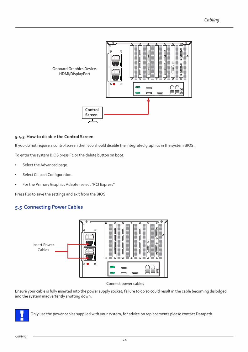
5.4.2 Connecting the Control Screen (Optional)
Most Datapath systems are configured to boot off the onboard graphics device therefore there may be a requirement to connect a control screen. The control screen is a standalone monitor which is separate from the monitors on the display wall. The control screen is configured as the Primary monitor in the Windows® Display Settings and the display wall is configured as the Secondary monitor.
Connect the control screen as follows:
Twelve Screen Display Wall
Corresponding Graphics Outputs
1
23
4
5
6
7
8
9
10
11
12
Cabling24
Cabling
5.4.3 How to disable the Control Screen
If you do not require a control screen then you should disable the integrated graphics in the system BIOS.
To enter the system BIOS press F2 or the delete button on boot.
• Select the Advanced page.
• Select Chipset Configuration.
• For the Primary Graphics Adapter select “PCI Express”
Press F10 to save the settings and exit from the BIOS.
Onboard Graphics Device. HDMI/DisplayPort
5.5 Connecting Power Cables
Connect power cables
Only use the power cables supplied with your system, for advice on replacements please contact Datapath.
Ensure your cable is fully inserted into the power supply socket, failure to do so could result in the cable becoming dislodged and the system inadvertently shutting down.
Control Screen
Insert Power Cables

Operation
Chapter 6 - Operation
This chapter will cover:
• Switching on
• Initial system boot on delivery
• Setting up the operating system
• Opening WallControl 10/Wall Control-red
• Displaying source captures
6.1 Switching On
When switching the system on for the first time you will need to complete the initial system boot steps as described in Initial System Boot on Delivery below.
6.1.1 Switching on the System
Ensure the mains power cable is correctly connected then turn on the VSNMicro 600.
25
Turn on the main system power switch which is located on the front panel.
The BIOS and boot messages will be displayed on the control screen (if connected) as the system boots. Once the system boot up is complete, the display wall will open up into a Windows® desktop.
6.2 Initial System Boot on Delivery
Once the system has been configured in the factory the operating system is resealed, meaning that when switching on the system for the first time the operating system setup commences.
You will be prompted to enter information to set up your VSNMicro 600.
6.2.1 Select Language Pack
You will now be prompted to set up your Windows® 7 operating system starting with selecting the language option you require. Language selection is the responsibility of the customer and is not part of the system pre configuration prior to shipment. Windows® 7 language settings can be changed using Control Panel/Region and Language on the Keyboard and Languages tab. Language packs are available to download as optional updates through Windows Update. The following languages are pre-installed:
• Simplified Chinese
• English (UK)
On/Off
Operation26
Operation
• English (USA)
• French
• German
• Italian
• Japanese
• Polish
• Portuguese (Brazilian)
• Russian
• Spanish
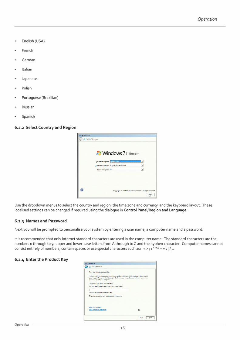
6.2.2 Select Country and Region
Use the dropdown menus to select the country and region, the time zone and currency and the keyboard layout. These localised settings can be changed if required using the dialogue in Control Panel/Region and Language.
6.2.3 Names and Password
Next you will be prompted to personalise your system by entering a user name, a computer name and a password.
It is recommended that only Internet standard characters are used in the computer name. The standard characters are the numbers 0 through to 9, upper and lower-case letters from A through to Z and the hyphen character. Computer names cannot consist entirely of numbers, contain spaces or use special characters such as: < > ; : “ ?* + = \ | ? ,.
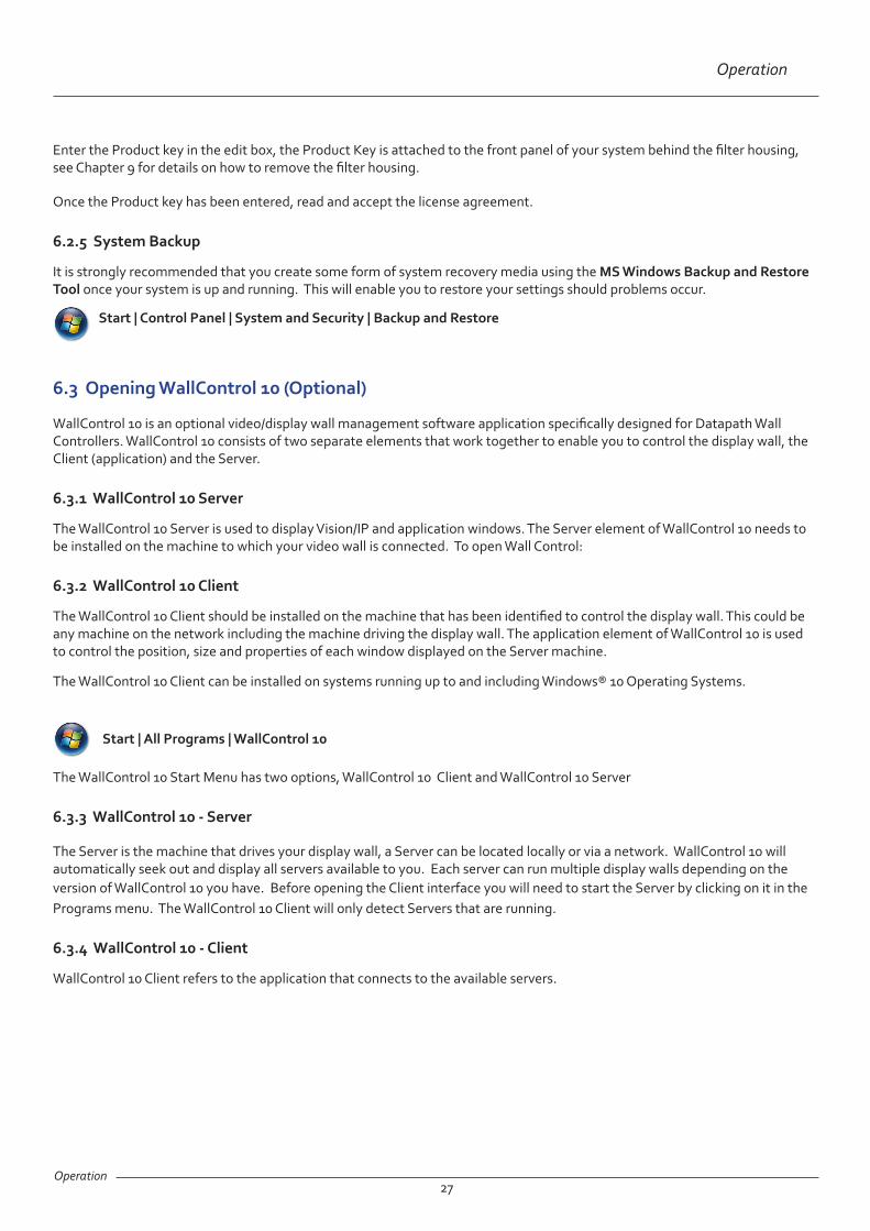
6.2.4 Enter the Product Key
Operation27
Operation
Enter the Product key in the edit box, the Product Key is attached to the front panel of your system behind the filter housing, see Chapter 9 for details on how to remove the filter housing.
Once the Product key has been entered, read and accept the license agreement.
6.2.5 System Backup
It is strongly recommended that you create some form of system recovery media using the MS Windows Backup and Restore Tool once your system is up and running. This will enable you to restore your settings should problems occur.
Start | All Programs | WallControl 10
The WallControl 10 Start Menu has two options, WallControl 10 Client and WallControl 10 Server
6.3.3 WallControl 10 - Server
The Server is the machine that drives your display wall, a Server can be located locally or via a network. WallControl 10 will automatically seek out and display all servers available to you. Each server can run multiple display walls depending on the version of WallControl 10 you have. Before opening the Client interface you will need to start the Server by clicking on it in the Programs menu. The WallControl 10 Client will only detect Servers that are running.
6.3.4 WallControl 10 - Client
WallControl 10 Client refers to the application that connects to the available servers.
6.3 Opening WallControl 10 (Optional)
WallControl 10 is an optional video/display wall management software application specifically designed for Datapath Wall Controllers. WallControl 10 consists of two separate elements that work together to enable you to control the display wall, the Client (application) and the Server.
6.3.1 WallControl 10 Server
The WallControl 10 Server is used to display Vision/IP and application windows. The Server element of WallControl 10 needs to be installed on the machine to which your video wall is connected. To open Wall Control:
6.3.2 WallControl 10 Client
The WallControl 10 Client should be installed on the machine that has been identified to control the display wall. This could be any machine on the network including the machine driving the display wall. The application element of WallControl 10 is used to control the position, size and properties of each window displayed on the Server machine.
The WallControl 10 Client can be installed on systems running up to and including Windows® 10 Operating Systems.
Start | Control Panel | System and Security | Backup and Restore

Operation28
Operation
A detailed summary of WallControl 10 features can be found in Chapter 7, alternatively a comprehensive help file with video tutorials is available within the application.
6.3.5 WallControl 10 - User Interface
Tools:
Sources Layouts Templates
Open the application by selecting WallControl 10 Client and the user interface will be launched.
6.4 Opening Wall Control (Optional)
Wall Control is an optional video/display wall management software application specifically designed for Datapath Wall Controllers. Wall Control consists of two separate elements that work together to enable you to control the display wall, the Wall Control Application and the Wall Control Server.
6.4.1 Wall Control Application
The Wall Control Application should be installed on the machine that has been identified to control the display wall. This could be any machine on the network including the machine driving the display wall. The application element of Wall Control is used to control the position, size and properties of each window displayed on the Server machine.
6.4.2 Wall Control Server
The Wall Control Server is used to display Vision/IP and application windows. The Server element of Wall Control needs to be installed on the machine from which you wish to create Vision/IP and application windows. To open Wall Control:
Start | All Programs | Wall Control
The Wall Control Start Menu offers two methods of opening the application, Wall Control and Wall Control-My Computer.
Operation
Operation29
6.4.3 Wall Control-My Computer
Wall Control-My Computer refers to your system having both the Wall Control Application and the Wall Control Server installed. Selecting Wall Control-My Computer will open the Wall Control application window having activated both the Server and the Application. The application window will display all inputs available in the system.
6.4.4 Wall Control
Selecting Wall Control will launch the application window but will not connect to a Wall Control Server. For more information regarding connecting to a Wall Control Server, consult the application help file.
6.5 Displaying Video Captures
Once a connection to a Wall Control-red server has been established then windows can be created for display on your video/display wall. Some video formats may not be supported, see Installing video CODECS in the Advanced User Chapter.
Windows can be created using the New menu or the application Toolbar.
6.5.1 New Menu
Displays options for each window type: Preset Window Vision Window IP-Camera Window Run an Application
6.5.2 Toolbar
The application Toolbar displays a list of the type of windows that can be opened, depending on the hardware you have installed in your machine.
To open the required inputs:
Select the required input using the cursor and drag to a preferred position on the wall.
Double click on the required input and the window will open, positioned at the top left of the display wall.
Open multiple inputs by pressing the shift key and clicking the required number of inputs with the mouse.

Operation
Operation30
A detailed summary of Wall Control-red features can be found in Chapter 7, alternatively a comprehensive help file system is available within the application, select Help | Contents
New Menu
Toolbar
Optional Control Screen
Display Wall Representation

Software
Chapter 7 - Software
31
This chapter will cover:
• WallControl 10
• Wall Control
• Wall Monitor
• Utilities
7.1 WallControl 10 (Optional)
The optional WallControl 10 software application is pre-installed and tested prior to shipment of your VSNMicro 600 therefore no installation of the software is required.
WallControl 10 offers real time management of small, medium and large scale display walls, it enables you to create multiple walls (WallControl 10 PRO) which can all be controlled by a single wall controller system .
You can use WallControl 10 to interactively move, size and position local application windows, video capture and IP-Camera windows. WallControl 10 allows you to save specific wall layouts as .dpl files enabling them to be shared with other users and re-called when required.
7.2 WallControl 10 - Features and Tools
7.2.1 Layout Files
Save, recall and share specific desktop configurations using layout files.
7.2.2 Sources
Sources are grouped by type or by location in the Sources Tab. All sources can be allocated search strings which enables users to quickly find and display specific sources.
7.2.3 Templates
Templates are tools designed to assist in the creation of the layout of your display wall. Templates can be used to create visual displays over numerous screens to enable you to showcase specific content to target audiences. A number of pre-defined templates are available on the Template tab.
Three types of template are available:
Desktop Template - Allows you to create a template to cover the whole of your display wall.
Free Floating Template - A template can be placed on top of a video window. The template can be dragged anywhere on the wall and re-sized.
Custom Templates - Design your own custom template and save it to the template library. It can then be used as a Desktop or Free Floating template.
7.2.4 Wall Creator (WallControl 10 PRO)
Wall Creator enables you to create multiple walls from one single display wall. Each wall created can operate independently, having its own sources and templates.

Software32
Software
7.2.5 Carousel
The Carousel function allows you to define a number of sources which a window will cycle through, allowing each input to be viewed in turn for a specified duration. The edit panel allows you to set the duration of each source in the Carousel cycle and
create a buffer if required.
7.2.6 Vision and IP Window
Control over presenting captured video and IP camera streams on the display wall. Configure window properties including:
• Position and size of windows
• Aspect ratio enforcement
• Show window borders.
7.2.7 Local Application Windows
Support for controlling applications such as Internet Explorer or Microsoft Powerpoint. Applications can be opened direct from the WallControl 10 Sources Tab.
7.2.8 Audio Support
Control digital and analogue audio content associated with specific Vision windows.
7.2.9 Multiwall (WallControl 10 PRO)
Configure a single system to drive multiple walls.
7.3 Wall Control (Optional)
The optional Wall Control software application (Wall Control-red / Wall Control-SQX depending on your order) is pre-installed and tested prior to shipment of your system therefore no installation of the software is required.
Wall Control displays the desktop of the machine that is being controlled. It allows you to remotely display Vision, IP-Camera (Wall Control-SQX required) and Application windows across a network on another machine or locally on the same machine.
You can use Wall Control to interactively move, size and position application windows and control Vision and IP-Camera windows by using the Windows Properties sheet. Wall Control also has a guide and grid function to aid the positioning of windows on the display wall.
Wall Control allows you to save specific wall layouts as .lay files enabling them to be re-called when required.
There is an area of the application around the desktop where windows can be dragged allowing them to be manipulated without being displayed on the video/display wall.
Software
Software33
7.3.2 Wall Control - Features and Tools
Wall Control has a range of advanced features to enable you to manage your video/display wall either locally or remotely over a network. The following list provides a brief summary of the features and tools contained within the application. However, all the features and tools are documented in depth in the Wall Control-red help file which can be accessed through the Help menu or by pressing F1 when the application is active.
7.3.3 Layout Files
Save and recall specific desktop configurations using layout files. Window properties including the position, size and any On Screen Displays are also saved in layout files.
7.3.4 Offline Configuration
The Wall Control offline layout editor allows layout files to be created and edited without physically displaying any windows on the display wall. Wall Control can be connected offline on either the server machine or a machine without any display wall hardware, for example a laptop.
An offline connection in Wall Control is initiated by opening a configuration file. This file must have been exported from a server machine and will contain a snapshot of the hardware and software configuration on that machine.
7.3.5 Vision and IP Window
Control over presenting captured video and IP camera streams on the display wall. Configure window properties including:
• Position and size of windows
• Aspect ratio enforcement
• Exclude window borders and menu bar
• Create on screen display captions
• Control capture rate
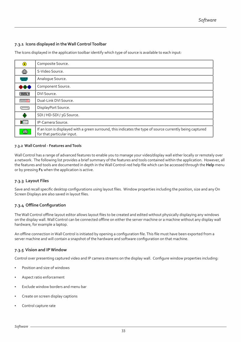
7.3.1 Icons displayed in the Wall Control Toolbar
The Icons displayed in the application toolbar identify which type of source is available to each input:
Composite Source.
S-Video Source.
Analogue Source.
Component Source.
DVI Source.
Dual-Link DVI Source.
DisplayPort Source.
SDI / HD-SDI / 3G Source.
IP-Camera Source.
If an Icon is displayed with a green surround, this indicates the type of source currently being captured for that particular input.
Software
Software34
7.3.6 Application Windows
Support for controlling applications such as Internet Explorer, Microsoft Powerpoint. Application can be opened direct from the Wall Control Toolbar, through the Command Line Interface or from previously saved layout files.
7.3.7 On Screen Display (OSD)
Highly configurable OSD function to overlay bitmaps (not on all types of window) and text over Vision and IP-Camera windows (excluding SQX windows). Add descriptions and logos with transparency support and create specific display variables such as frame rates.
7.3.8 Carousel Support
The Carousel function can automatically cycle through configured lists of different inputs for Vision and IP-Camera windows over defined time periods. A double buffering mechanism will automatically start IP-Camera streams prior to the carousel input switch.
7.3.9 Split into Sub- Windows
Divide an active Vision window into sub-windows. Each sub-window will display a cropped portion of the original Vision window.
7.3.10 Audio Support
Control digital and analogue audio content associated with specific Vision windows.
7.3.11 Command Line Interface
Wall Control-red/Wall Control-SQX comes with a powerful Command Line Interface to enable you to automate almost any operation from opening layout files, moving windows around the display wall and changing specific input settings.
7.3.12 Support for Crestron /AMX Controllers
• Remote Command Line Interface for automation via Crestron/AMX Controllers:
• Control the display wall remotely from a Crestron/AMX controller
• Access to the full local Command Line Interface
• Support for RS-232 (via serial cable) and TELNET (via a local network)
• Integrated user interface support to configure and monitor the Remote Command Line

Software35
Software
7.4 Wall Monitor (Optional)
The optional Wall Monitor software application enables you to monitor the temperatures and voltages of the following system components:
• Backplanes
• Capture Cards
• SQX Cards
• SBC
• CPU Cores
• Graphics Cards
Should any overheating or voltage surge be imminent within the system, the Wall Monitor application will alert the user via a pre-configured alarm.
When running, the Wall Monitor application can display a transparent floating icon which can be placed anywhere on the desktop.
Cursor tooltips are available throughout the application offering information and advice. Hover the cursor over different areas of the application to reveal the tooltips. The application also has a help file to assist you, click on any help button or press F1 on your keyboard to access the help files.
Wall Monitor Icon
Left click the centre of the icon to open the application or right click to display the application menu.
Left click and hold on the border of the icon to move it around the desktop.
7.4.1 Monitoring System Components
Each of the system components listed above have built in temperature and/or voltage sensors which enables the Wall Monitor application to display any increase or decrease in voltage and temperature. The temperature and voltage ranges are graded as follows:
Green = Normal operating conditions
Amber = An indication that voltages or temperatures are operating outside of normal thresholds and if configured and alarm will activate.
Red = Indicates that the voltages or temperatures have exceeded the acceptable working thresholds and a system shutdown is imminent.

Software
Software36
7.4.2 Wall Monitor Application Window
The Wall Monitor application window (above) is displaying the temperature of the capture cards in the system. To view different components, click on the relevant tabs. Temperatures can be displayed in either degrees Fahrenheit or degrees Celsius.
7.4.3 Configuring Alarms
Wall monitor allows you to configure three types of alarm to warn of impending problems:
System Buzzer - The system buzzer can be configured to determine the amount of time the buzzer will be audible up to a maximum of 5 seconds, an audio alarm is activated within the system. On some systems, speakers may have to be connected.
Email - Should you not be in the proximity of your system and email warning can be configured. An email is sent to a nominated email address giving details of impending problems.
On Screen - Text is displayed on screen to warn of impending problems with the system. The Wall Monitor icon adopts an amber border when the alarm is issued.
7.4.4 Current Status
At any time you can check the current status of the monitored components by selecting Show Current Status in Browser from the Application menu. This will display a browser window, similar to the following:
Summary of the status of all monitored devices

Software
Software37
7.5 Vision Application (Optional)
When purchased separately, Vision capture cards are supplied with a powerful software application for configuring the format of input sources and displaying the data.
7.5.1 Video Streaming
DirectShow drivers for WDM Streaming driver supports the following applications, to encode, record and stream video over networks or the Internet:
• Microsoft Media Encoder®
• VLC
• VirtualDub
• Any other DirectShow encoding software
For streaming applications, Vision cards can be used with Windows Media Encoder to compress and stream captured video. To replay the video, use Windows® Media Player.
Any application compatible with Windows® DirectShow technology can use Vision capture cards due to their built-in WDM support.
7.5.2 Vision Software Capabilities
Timestamp support for streaming synchronisation:
• Synchronisation of multiple inputs across multiple cards
• Synchronise systems using network clock synchronisation
• For edge blending and other applications
Flexible and configurable EDID Management:
• Allows programming of custom EDID parameters for capture cards
Low Input to Output Capture Latency.
DMA to third party graphics vendors back and front buffers via Direct3D:
• Compatibility with AMD DirectGMA
• Compatibility with Nvidia GPUDirect
User Mode filter for source selection:
• Enables cropping support in DirectShow on all inputs
• Supports Start and Stop trigger interface on all Visi0n inputs
Datapath Unified Vision Driver:
• Multiple cards per system, 16 streams per device
• Frame sync and time stamping

Software
Software38
• DirectShow interface
• The RGBEasy API for advanced audio and video control
• Fully integrated for use with Datapath Wall Control software for video wall applications
7.5.3 MultiStream
Datapath’s MultiStream feature is available on all Datapath capture cards and enables multiple, independently formatted video streams to be set up in parallel.
Each stream can be formatted completely independently and individual selection of resolution, colour space and cropping region can be set for each stream. This maximises bandwidth utilisation of the capture card and PCIe interface, and also simplifies development tasks for application developers who do not need to implement video stream reformatting separately.
7.5.4 Vision Application Overview
The application displays the connected source in a window; it has the following features:
• Scales the data to fit in the window
• Ability to set up sources accurately (settings automatically saved)
• Save a single frame to a file in one of the following formats: BMP, JPEG, GIF, TIFF, PNG
• Print a single frame
• Maintain the aspect ratio of the displayed captured data
• Cropping
• Display text over the data (on-screen display)
• Command line interface
• HDCP supported (not supported in SQX encoding)
• Help file documenting all features
Note:
The supplied drivers and software require you are using :
• Up to Windows® 10

Software
Software39
7.6 Software Utilities
Datapath provides a group of software utilities designed to assist you to fine tune your system for specific individual system requirements. All the software utilities can be found on the Recovery Media that was shipped with your system, alternatively, you can download the most up-to-date versions from the Datapath website.
7.6.1 Desktop Utility
Used to define a desktop resolution which can compensate for display bezels or projector overlap.
7.6.2 Custom Mode Utility
A utility for defining custom display timings for video modes not available in the display driver or EDID.
7.6.3 Multi Resolution Configuration Tool (MultiResConfig)
Developed to assist in the design and configuration of a video wall that contains a mixture of multi resolution displays.
7.6.4 Diagnostic Tool (diagtool)
A diagnostic tool that gathers information to assist in diagnosing problems with hardware and software configurations. Information is gathered and compressed into a zip file for onward transmission to the Datapath Support Team.
7.6.5 PCICFG Tool
A diagnostic program that prints out the PCI configuration information. Note, this tool must be run from either a USB or MSDOS boot disk, it cannot be run from Windows®.
7.6.6 Sleep Utility
Designed to generate a pause within a script. This can be used when sequencing the loading of files or application windows.
Troubleshooting40
8.1 Technical Support
Registered users can access our technical support using email and the Support Enquiry Form on our website, usually with a response within 24 hours (excluding weekends).
8.1.1 Email
Send an email to [email protected] with as much information about your system as possible. To enable a swift response our support team will need to know the following details:
• Specification of the PC - including processor speed.
• Operating system.
• Application Software.
• Datapath Hardware/Software.
• The exact nature of the problem - please be as specific as possible.
Please quote version and revision numbers of hardware and software wherever possible.
8.1.2 Support Procedures
During the support process you may be asked by one of our support staff to carry out certain tasks and procedures to assist them in solving any problem you may encounter. Details and up to date instructions can be found in the support section of the Datapath website.
Chapter 8 - Technical Support
Maintenance41
Chapter 9 - Maintenance
9.1 Filter Maintenance
The system filter is an integral part of the VSNMicro 600 and as such it needs to be maintained correctly. Failure to maintain the filter can result in the system overheating and causing it to fail. In normal operating conditions the filter should be removed and cleaned every 3 months. However, this 3 month period is a guide only and it can be increased to every 6 months or decreased to one month depending on the levels of dust in the environment the system is operating in.
It is recommended that the condition of the filter is checked at regular intervals.
The filter can be removed and cleaned whilst the system is in operation, system shut-down is not necessary.
Note:
Failure to maintain the system filter could result in damage to your system and invalidate the warranty.
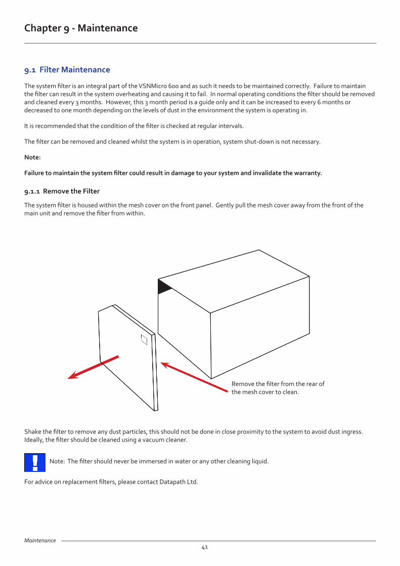
9.1.1 Remove the Filter
The system filter is housed within the mesh cover on the front panel. Gently pull the mesh cover away from the front of the main unit and remove the filter from within.
Shake the filter to remove any dust particles, this should not be done in close proximity to the system to avoid dust ingress. Ideally, the filter should be cleaned using a vacuum cleaner.
Note: The filter should never be immersed in water or any other cleaning liquid.
For advice on replacement filters, please contact Datapath Ltd.
Remove the filter from the rear of the mesh cover to clean.

Environmental
Chapter 10 - Environmental
10.1 Certification and Compliances
10.1.1 CE
42
EU- Class A Declaration of Conformity
Datapath Ltd declares that the VSNMicro 600 Wall Controller covered in this User Guide complies with the essential require-ments and other relevant provisions of Directives 2001/108/EC and 2011/65/EU.
A copy of our Declaration of Conformity is available on request:
Datapath Ltd Bemrose House Bemrose Park Wayzgoose Drive Derby, DE21 6XQ United Kingdom
10.1.2 FCC
These devices comply with part 15 of the FCC Rules. Operation is subject to the following two conditions: (1) These devices may not cause harmful interference, and (2) these devices must accept any interference received, including interference that may cause undesired operation.
This equipment has been tested and found to comply with the limits for a Class A digital device, pursuant to part 15 of the FCC Rules. These limits are designed to provide reasonable protection against harmful interference when the equipment is operated in a commercial environment. This equipment generates, uses and can radiate radio frequency energy and, if not installed and used in accordance with the instruction manual, may cause harmful interference to radio communications. Operation of this equipment in a residential area is likely to cause harmful interference in which case the user will be required to correct the interference at their own expense.
Caution. Changes or modifications to the equipment not expressly approved by the party responsible for compliance could void the user’s authority to operate the equipment
10.1.3 Disposal
At the end of life all Datapath products should be disposed of as per local laws and regulations dictate. In the UK contact Datapath to arrange disposal. Our WEE registration number is WEEE/AA0005ZR.

Specifications
Chapter 11 - Specifications
43
This chapter will cover:
• Technical drawings of the chassis
• Technical specification of the VSNMicro 600
11.1 Technical Drawings
250mm
175mm
320mm
Front View
Side View
Specifications44
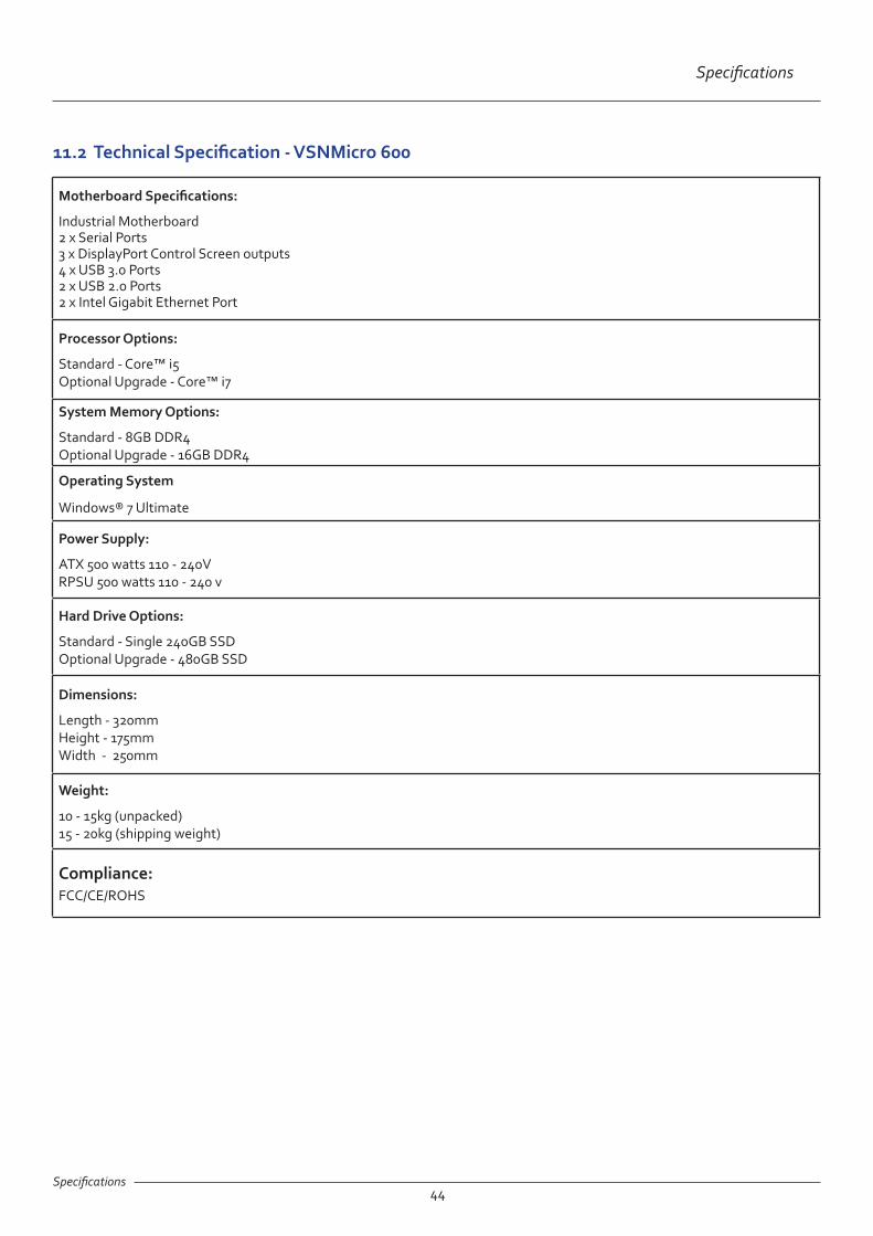
11.2 Technical Specification - VSNMicro 600
Motherboard Specifications:
Industrial Motherboard 2 x Serial Ports 3 x DisplayPort Control Screen outputs 4 x USB 3.0 Ports 2 x USB 2.0 Ports 2 x Intel Gigabit Ethernet Port
Processor Options:
Standard - Core™ i5 Optional Upgrade - Core™ i7
System Memory Options:
Standard - 8GB DDR4 Optional Upgrade - 16GB DDR4
Operating System
Windows® 7 Ultimate
Power Supply:
ATX 500 watts 110 - 240V RPSU 500 watts 110 - 240 v
Hard Drive Options:
Standard - Single 240GB SSD Optional Upgrade - 480GB SSD
Dimensions:
Length - 320mm Height - 175mm Width - 250mm
Weight:
10 - 15kg (unpacked) 15 - 20kg (shipping weight)
Compliance:FCC/CE/ROHS
Specifications

Warranty
Chapter 12 - Warranty
12.1 Warranty Statement
Datapath provides a return to manufacturer warranty on all its products for a standard 36 month period, see the table below for non standard warranty periods. It is important that RMA procedures are followed prior to products being returned as often issues can be resolved quickly without the need for products being returned.
45
ComponentStandard 36
Month Warranty12 Month Warranty
Image DP4 Graphics Cards X
Vision Capture Cards (including ActiveSQX) X
Power Supply Units X
Hard Drives, RAM, Fans X
12.2 RMA Returns Policy
If your Datapath product is not working as you expect, we recommend that you contact Datapath Ltd in the first instance for support, since many issues that may first appear as hardware faults, are actually installation or set-up problems and can normally be resolved without having to ship any hardware back to us. This route is therefore often the quickest, easiest and cheapest way of solving the problems that you are experiencing. Please email [email protected] including as much detail regarding the failure as possible (for example: system description, signal types, input or output resolutions and any other relevant background information).
It is essential for you to know the serial number of the product(s) when contacting us.
If it appears that the fault is most likely to be hardware related, please email [email protected] stating the serial number and as much additional information regarding the nature of the failure as possible. Detailed explanation of the fault will help us to better identify the problem and will direct additional focused testing if necessary. We will then issue an “RMA Number” to you.
At the time that the “RMA Number” is issued we will inform you of the warranty status of the product and the cost of the repair, if appropriate - see paragraph (b) below. The product should then be returned, at your cost, too Datapath Ltd following the steps below.
There are 4 possible scenarios when a product is returned to us:
(a) The product is in warranty and is either found to be genuinely faulty or no fault is found. In these cases, the product will be repaired as necessary, or replaced by a new or previously repaired product, and returned to you at our cost.
(b) The product is out of warranty and is found to be faulty. The product if possible will be repaired or replaced at fixed cost, as stated in the RMA authorisation email. To cover this payment, you will be required to either provide a Purchase Order or Credit Card details, when the product is returned to us. (However, we will not issue an invoice or charge the credit card until the repair has been completed and is about to be returned to you)
(c) The product is in warranty but is found to be damaged by misuse. This will be treated as (b) above.
(d) The product is out of warranty and is obsolete. In the unlikely situation that the product can be neither repaired nor replaced, because some of it’s components are obsolete and we have no swap-out stock left, then the product will either be returned to you, or disposed of at your request, with no charge.

Warranty46
PLEASE NOTE: Datapath will not accept responsibility for the safety, integrity or security of any programmes, data or other content held on hard drives or any other type of rewritable media which is sent to us either separately or as part of any equipment returned to us for repair or for any other purpose. Customers are advised to take back-ups of anything that they deem to be valuable or important before returning the equipment to us and anything which is confidential should be erased from the media before it’s returned.
Once the RMA Number has been issued, you need to raise your Purchase Order, or supply your credit card details, and return the product to: Datapath Ltd, Bemrose House, Bemrose Park, Derby DE21 6XQ, United Kingdom - securely packed and with the RMA Number clearly displayed on the outside of the box. To prevent unnecessary carriage and handling please only send back products or accessory items you believe to be faulty.
In the case of paragraph (c) , the fixed charge will be levied after we have seen the product and identified the misuse. In this case we will request you to issue a purchase order or provide credit card details before any repairs are completed.
Our policy is to return the repair (or swap-out) to you within 10 days of receipt.
Warranty

Advanced Users
Chapter 13 - Advanced Users
47
This chapter is aimed towards advanced users and covers the following:
• Verifying RAID (Optional 480GB SSD Upgrade)
• Installing CODEC Packs to play video
• Updating Firmware
• System Recovery
13.2 Verify RAID (Optional 480GB SSD Upgrade)
To verify the RAID set up on your VSNMicro 600 follow these instructions.
13.2.1 Enter the BIOS Setup
Restart the VSNMicro 600 and press the keyboard delete button when the Boot-Up splash screen is displayed. This will direct you to the BIOS Setup Utility.
Use the keyboard arrows to navigate across to the Advanced Tab:
• Confirm that Configure SATA#1 is set to RAID.
• Press F10 to save and exit the BIOS Utility.
When the wall controller restarts press CTRL+i at the BIOS splash screen to enter the RAID BIOS utility.
13.2.2 Degraded RAID Array
If a RAID array degrades this does not necessarily mean that the hard drive or any other hardware within the system is faulty. What it does mean is that there is an inconsistency in DATA across the array. This could be caused by many different factors including a BSOD, the system hanging, an application conflict or power outage.
As stated above, the degrade of a RAID array does not necessarily mean hardware failure but should the problem occur on a regular basis then further diagnostics should be performed/undertaken. It is recommended, as with any system, that regular backups are made to safeguard information.
If a RAID array is degraded take note of the physical port number and the drive serial number of the degraded disk. The degraded disk will normally be highlighted with an error in red in the RAID BIOS Utility. Working drives are normally set to green.
Use the keyboard arrow keys and navigate to Reset disks to Non-RAID and press enter.
Use the keyboard arrow keys to select the degraded disk and press the keyboard spacebar to assign it for Reset.
Warning! Ensure the correct disk is selected before continuing.
Once a disk has been reset the BIOS RAID Utility will detect the disk as a new one and a prompt will appear asking if you want to use the selected disk to repair the RAID. Accept and continue.
Both disks should now be displayed as Member Disk (x) with the status highlighted in yellow as Rebuild.
Exit the Utility by clicking Esc and RAID will commence the rebuild process once the operating system has loaded.
48
Advanced Users
13.3 Installing CODEC Packs to Play Video
DGCPlay utilises the DirectShow codecs installed on the computer to playback a video file. A standard installation of Windows includes codecs for playing WMV files, plus some AVI and MPG files. Many video files require additional 3rd party codec files.
For many of AVI and MPG formats the open source ffdshow package will contain codecs which will allow playback using DGCPlay. ffdshow is available from:
http://ffdshow-tryout.sourceforge.net
MOV files are supported through QuickTime. By default QuickTime is not available through DirectShow. With additional software it is possible to make QuickTime video files available however. There are a number of codecs which do this, for instance:
Advanced Users
http://www.codecguide.com/download_kl.htm
http://www.riverpast.com/en/prod/quicktime/
http://www.medialooks.com/products/directshow_filters/quicktime_filter.html
SWF and FLV files are supported by Flash. In the same manner as QuickTime these are not natively supported by DirectShow, although it is possible to use additional software to enable playback. A suitable codec for this might be:
http://www.medialooks.com/products/directshow_filters/flash_source.html
Datapath do not provide any warranty or assurance that these examples will be suitable for commercial use. We simply list them as an example of those available through 3rd parties. Before deployment we advise that any of the above, and any other codec selected, is thoroughly evaluated to confirm their suitability.
13.4 Firmware Updates
The procedures for updating the firmware of your cards can be found in the relevant user guide which is available on your Datapath Recovery Media. Check the Datapath website for the latest version of the user guides.
13.5 Restoring to Factory Settings
To restore your VSNMicro 600 to its factory settings you will need the recovery media supplied with your system. If you no longer have your recovery media, contact [email protected] for advice in obtaining a replacement.
Ensure your VSNMicro 600 is turned off and insert the recovery media (USB Stick) into a USB port.
13.5.1 Selecting a Boot Device
With the USB recovery media inserted, switch on your VSNMicro 600 and press F8 when the Splash Screen is displayed to enter the Select Boot Device screen.
From the list of boot devices, select the NON UEFI USB media and click on OK.
At this point, if Windows® fails to start this indicates that the wrong boot device was selected. In this instance, select Esc to exit and start the process again.
The VSNMicro 600 will reboot with the boot messages appearing on your control screen (if set) or the first screen on your video wall. When prompted, accept the terms and conditions and then follow the instructions to restore your wall controller.

Advanced Users
49Advanced Users
13.5.2 Reactivate Windows®
When the VSNMicro 600 has been restored the Windows® operating system will need to be re-activated. The software key can be found inside the front panel of your VSNMicro 600.
13.5.3 Install Display Drivers and Software
Once the Windows® re-activation process is complete the Display Drivers need to be re-installed and if required, the Wall Con-trol application software. The Display Drivers and WallControl 10 software can be found in the Driver and Tools folder on the recovery media.
For the latest drivers and software go to www.datapath.co.uk

50
Index
Index
A
Activate Windows®7 10
Associated Output/Input Cards 18
C
Contents 6
Control Screen 23
Custom Brackets 18
D
Desktop Utility 39
Diagnostic Tool 39
Dimensions 44
Disable the Control Screen 24
Disclaimer 5
Displaying Video Captures 25
Display Setup 11
Disposal 42
E
Email Support 40
Ethernet Ports 19
F
FCC Rules 42
Firmware Updates 48
Fitting the Power Supply Modules 20
Fonts and Symbols 14
G
Graphics Card 22, 35
I
Initial Inspection 17
Install Display Drivers and Software 49
Installing CODEC Packs 48
K
Keyboard 6
L
Language Pack 25
M
Maintenance 16
Manufacturer Warranty 45
Multi Resolution Configuration Tool 39
N
Network Security 21
O
Offline Configuration 33
Overheating 35
Overview 18
P
PCICFG Tool 39
Power Cables 24
Powering up the System 9
Power Supply 16
Power Supply Module 20
Power Supply Units 9, 20
Product Datasheets 18
Product End of Life 42
Product Key 26
Q
Quick Start Guide 6
R
RAID 47
Range of Datapath Products 18
Reactivate Windows® 49

51
Index
Index
Recovery Media 48
Remove the Filter 41
Removing the Power Supply Modules 20
Restore your Wall Controller 48
Returns Policy 45
RMA Number 45
S
Safety 16
Screen Order 22
Selecting a Boot Device 48
Show Current Status 36
SQX 15
Support Procedures 40
Symbols 14
System Backup 27
System Buzzer 36
System Filter 41
T
Technical Drawings 43
Technical Specifications 43
Temperature and Voltage Ranges 35
Terminology 15
U
Updating Firmware 48
Utilities 39
V
Video Streaming 37
Vision Application 37
VisionAV 18
VisionAV-HD 18
VisionAV-SDI 18
VisionSC-DP2 18
W
WallControl 10 - Client 27
WallControl 10 - Server 27WallControl 10 - User Interface 28
Wall Control 12
Wall Control Icons 33
Wall Control-red 13, 15, 32
Wall Control-red Features 28, 30
Wall Control-red-IP 32
Wall Control-SQX 32
Wall Control Toolbar 29
Wall Monitor Application 36
Wall Monitor Software 35
Windows®7 Setup 10