DigiBird Video Wall Controller
37
Transcript of DigiBird Video Wall Controller


All rights reserved by DigiBird ®
DigiBird Video Wall Controller Software User Guide
Research & Development, Manufacturer and SalesVideo & Image Processing Expert
All rights reserved by DigiBird ®
Table of Contents
I. Manual Copyright Notice…………………………………………………………………………………………………………1
II. Introduction…………………………………………………………………………………………………………………………1
2.1 About this guide………………………………………………………………………………………………………………1
2.2 About the software……………………………………………………………………………………………………………1
2.3 Features…………………………………………………………………………………………………………………………1
III. Software Installation………………………………………………………………………………………………………………2
3.1 System Requirements…………………………………………………………………………………………………………2
3.2 How to install DigiBird’s MultiView Controller Software…………………………………………………………………2
3.3 How to uninstall DigiBird’s MultiView Controller Software………………………………………………………………4
3.4 Connecting to DigiBird’s Video Wall Controller via Ethernet……………………………………………………………5
IV. Setup………………………………………………………………………………………………………………………………5
4.1 Logging in………………………………………………………………………………………………………………………5
4.2 Setting the IP address of DigiBird’s Video Wall Controller…………………………………………………………………6
4.3 Setting the IP address of the computer that installed the MultiView Controller Software:……………………………8
4.4 Testing the Ethernet Link……………………………………………………………………………………………………9
V. Using DigiBird’s MultiView Controller Software……………………………………………………………………………11
5.1 Starting and Exiting the MultiView Controller Software…………………………………………………………………11
5.2 Overview of the Main Application Window………………………………………………………………………………12
VI. System Configuration……………………………………………………………………………………………………………13
6.1 Connection / “Communication Settings”…………………………………………………………………………………13
6.2 Video Wall Configuration (Video Wall, input and output configuration)………………………………………………14
6.3 Video wall and output configuration………………………………………………………………………………………14
6.4 Input configuration……………………………………………………………………………………………………………17
6.5 Matrix switcher configuration………………………………………………………………………………………………17
6.6 Video Wall configuration……………………………………………………………………………………………………19
6.7 Monitors………………………………………………………………………………………………………………………20
6.8 Input……………………………………………………………………………………………………………………………20
6.9 Screen Mapping Settings……………………………………………………………………………………………………21
VII. The User…………………………………………………………………………………………………………………………21
VIII. License……………………………………………………………………………………………………………………………22
IX. Language Settings………………………………………………………………………………………………………………23
X. Windows and input signal management………………………………………………………………………………………23
10.1 Adding a window to the Workspace………………………………………………………………………………………25
A. Creating a window from the “Controller Input”………………………………………………………………………25
B. Creating a window from the “New” button on the Main menu………………………………………………………26
10.2 Closing windows……………………………………………………………………………………………………………27
10.3 Changing Z-order (layers)………………………………………………………………………………………………27
Top option………………………………………………………………………………………………………………………27
Bottom option…………………………………………………………………………………………………………………27
Up option………………………………………………………………………………………………………………………28
Down option……………………………………………………………………………………………………………………28
Locked position………………………………………………………………………………………………………………28
Moving a window………………………………………………………………………………………………………………28

All rights reserved by DigiBird ®
Grouping windows……………………………………………………………………………………………………………28
10.4 Zooming in on the windows………………………………………………………………………………………………29
10.5 Cropping an input source…………………………………………………………………………………………………30
XI. Scene design and control………………………………………………………………………………………………………30
11.1 Creating a scene……………………………………………………………………………………………………………30
11.2 Recalling a scene……………………………………………………………………………………………………………31
Technical Support……………………………………………………………………………………………………………………32

Research & Development, Manufacturer and SalesVideo & Image Processing Expert
All rights reserved by DigiBird ®1 All rights reserved by DigiBird ® 2
I. Manual Copyright Notice
This Operation Guide is the intellectual property of DigiBird®, © 2015. No portion of this guide may be copied
or reproduced in any manner or by any means, including, but not limited to electronic and electro-mechanical
reproduction, without the express written permission of DigiBird®.
II. Introduction
This section gives an overview of the guide and features of the DigiBird MultiView Controller Software and DigiBird
Video Wall Controller hardware. Topics include:
• About this Guide
• Overview of the DigiBird MultiView Controller Software
• Features
2.1 About this guide
This guide provides detailed information about the DigiBird MultiView Controller Software and DigiBird Video Wall
Controller hardware, including software installation and configuration.
This guide also describes how these applications control the DigiBird Video Wall Controller hardware.
The features and functionality described in this guide are based on version 5.14 of the DigiBird MultiView Controller
Software on windows 7 64-bit. For the latest details about these products, visit www.digibirdtech.com.
Manual version information
Version: 5.14
Release Date: July, 2014
2.2 About the software
The MultiView Controller Software is a Microsoft® Windows®-based application that is used to control the VWC (Video
Wall Controller) from your computer via an RS-232 or Ethernet cable.
2.3 Features
Some features of the MultiView Controller Software include:
• User Friendly Interface: The user interface is organized into a series of tasks so that you can easily navigate
through them and set up the video wall.
• Easy Configuration: Supports quick setup. The operation can be performed by simply clicking, dragging and
inputting configuration data.
• High Flexibility: Compatible with different application environments.

All rights reserved by DigiBird ®1 All rights reserved by DigiBird ® 2
• High Stability: Continuous updates to maintain high adaptability and stability.
III. Software Installation
3.1 System Requirements
To ensure that the DigiBird MultiView Controller Software functions correctly and reliably, you must install it on a
computer that meets or exceeds the following criteria:
Minimum Recommended
Operating System Windows XP® Windows XP® or Windows 7®
(32-bit or 64-bit)
CPUIntel Pentium/Celeron or faster, AMD Athlon or
fasterIntel Core i3 or faster
Memory (RAM) 256M RAM 2GB RAM
Hard Disk Free Space 150MB 5GB or higher
Graphics1024x768, 65K colors
(16-bit)
1024x768, 16.7M colors
(32-bit)
Network Card (Ethernet) 10Base-T 100BASE-T
Optical Driver CD-ROM DVD-ROM
Input Device Mouse and keyboard compatible with MicrosoftMouse and keyboard compatible with
Microsoft
3.2 How to install DigiBird’s MultiView Controller Software
Copy the installation file to your computer from the disc that came with the device.
When you double-click the installation file (MultiView Controller_5.14) to start the installation, you will receive a
notification from Windows “User Account Control”. Select “Yes”, and the installation will continue. After that, MultiView
Controller_5.14 automatically opens an installation wizard. Follow the remaining system prompts to complete the
installation.
Figure 3.2 A: Language Selection

Research & Development, Manufacturer and SalesVideo & Image Processing Expert
All rights reserved by DigiBird ®3 All rights reserved by DigiBird ® 4
Figure 3.2 B: Destination Folder
Figure 3.2 C: Installation Completed

All rights reserved by DigiBird ®3 All rights reserved by DigiBird ® 4
When the program is installed successfully, it will generate a shortcut on the desktop, as shown in the figure below:
Figure 3.2 C: Software Icon
3.3 How to uninstall DigiBird’s MultiView Controller Software
From the desktop, click Start > All Programs > MultiView Controller > Uninstall. When “User Account Control” appears,
select “Yes”. The Uninstall program will then start:
Figure 3.3 A: Uninstall the Software

Research & Development, Manufacturer and SalesVideo & Image Processing Expert
All rights reserved by DigiBird ®5 All rights reserved by DigiBird ® 6
Figure 3.3 B: Uninstallation Completed
3.4 Connecting to DigiBird’s Video Wall Controller via Ethernet
The computer with the installed MultiView Controller Software communicates with the DigiBird Video Wall Controller
via Ethernet. This can either be a direct or indirect connection. Connection to a single DigiBird Video Wall Controller
can utilize either method, but multiple DigiBird Video Wall Controllers must utilize an indirect method (for example, via
a hub or Ethernet switcher). The DigiBird Video Wall Controller’s Ethernet port is auto-sensing, so the Crossover Cable
and Straight-through Cable can both be used to connect to the Video Wall Controller.
IV. Setup
4.1 Logging in
To log in to the MultiView Controller Software:
• From the User drop-down list, select the desired role.
• In the Password field, enter the required password for the chosen role.
• The default user name is Admin, and the default password is left blank in the example below:

All rights reserved by DigiBird ®5 All rights reserved by DigiBird ® 6
Figure 4.1: Logging in
4.2 Setting the IP address of DigiBird’s Video Wall Controller
The first time you log in to the MultiView Controller Software and click “OK”, the following dialog box will appear:
Figure 4.2 A: Click OK to open settings
The above dialog box indicates you need to set the correct IP address for the computer and the Video Wall Controller
because the communication link between them has not been established. Clicking “Cancel”, will take you into demo
mode. When you click “OK”, the following dialog box will appear:
Figure 4.2 B: Connection settings

Research & Development, Manufacturer and SalesVideo & Image Processing Expert
All rights reserved by DigiBird ®7 All rights reserved by DigiBird ® 8
Click the “Advance” button; you can then set the IP address, subnet mask and gateway for the video wall controller:
Figure 4.2 C: Advanced settings
The Default IP address is 192.168.1.198; the subnet mask is 255.255.255.0, and the gateway is 192.168.1.1:
Figure 4.2 D: Change IP settings
Do not close the above dialog box because you now need to set the IP address for the computer that installed the
Multiview Controller software.

All rights reserved by DigiBird ®7 All rights reserved by DigiBird ® 8
4.3 Setting the computer’s IP address that installed the MultiView Controller
Software:
The network port on the computer must be configured to use the same communications protocol as the DigiBird Video
Wall Controller (TCP/IP). The computer must also be allocated an IP address on the same subnet as the DigiBird Video
Wall Controller.
To change the IP address for your computer, follow the instructions provided in your Windows program help file. Here
is a sample of how to change your IP address on Windows 7 (32-bit or 64-bit):
Figure 4.3 A: Computer’s IP Figure 4.3 B: Properties Figure 4.3 C: IP Settings
In this example, the computer’s IP address is set to 192.168.1.100 and the subnet mask is set to 255.255.255.0.
The DigiBird Video Wall Controller and the computer are in the same subnet. When you click the “OK” button in the
dialog box, as shown in the figure below, the main application window will appear:
Figure 4.3 D: IP Address

Research & Development, Manufacturer and SalesVideo & Image Processing Expert
All rights reserved by DigiBird ®9 All rights reserved by DigiBird ® 10
Figure 4.3 E: Software main interface
4.4 Testing the Ethernet Link
To test the connection of the Ethernet link between the computer and the DigiBird Video Wall Controller, you can use
the Ping utility.
A. Enter a ping command from your desktop.
• For Windows XP, 2000, and NT:
a. On the desktop, click Start > Run. The Run dialog box will open.
b. In the Run dialog box, type the following command:
ping nnn.nnn.nnn.nnn —t
where nnn.nnn.nnn.nnn is the IP address of the DigiBird Video Wall Controller that you want to test.
c. Click OK or press the <Enter> key.
• For Windows 7:
a. On the desktop, click Start.
b. In the Search programs and files field at the bottom of the Start menu, enter ping nnn.nnn.nnn.nnn —t and press
<Enter>.
A command window opens showing a series of messages which are explained below.

All rights reserved by DigiBird ®9 All rights reserved by DigiBird ® 10
B. To close the ping utility, press <Ctrl + C> on your keyboard or click the X button in the upper-right corner of the command window.
Here is an example:
When you run the ipconfig utility in CMD mode, it displays the IP address of the computer that installed the DigiBird
MultiView Controller Software, as shown below:
Figure 4.4 A: Ping command
When you run the Ping utility, it displays a series of response messages which you can use to determine the state of the
communications link.
For example, if you send a ping command to a DigiBird Video Wall Controller with the address 192.168.1.198, you
should get a message similar to the following:
Research & Development, Manufacturer and SalesVideo & Image Processing Expert
All rights reserved by DigiBird ®11 All rights reserved by DigiBird ® 12
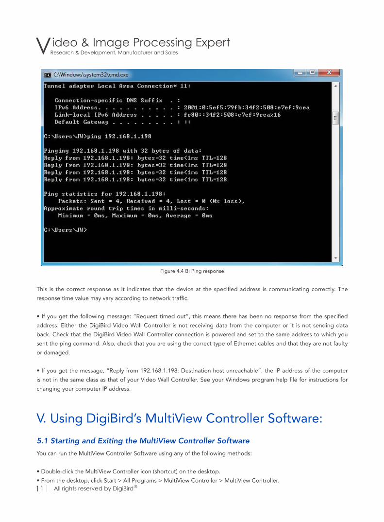
Figure 4.4 B: Ping response
This is the correct response as it indicates that the device at the specified address is communicating correctly. The
response time value may vary according to network traffic.
• If you get the following message: “Request timed out”, this means there has been no response from the specified
address. Either the DigiBird Video Wall Controller is not receiving data from the computer or it is not sending data
back. Check that the DigiBird Video Wall Controller connection is powered and set to the same address to which you
sent the ping command. Also, check that you are using the correct type of Ethernet cables and that they are not faulty
or damaged.
• If you get the message, “Reply from 192.168.1.198: Destination host unreachable”, the IP address of the computer
is not in the same class as that of your Video Wall Controller. See your Windows program help file for instructions for
changing your computer IP address.
V. Using DigiBird’s MultiView Controller Software:
5.1 Starting and Exiting the MultiView Controller Software
You can run the MultiView Controller Software using any of the following methods:
• Double-click the MultiView Controller icon (shortcut) on the desktop.
• From the desktop, click Start > All Programs > MultiView Controller > MultiView Controller.
All rights reserved by DigiBird ®11 All rights reserved by DigiBird ® 12
• Double-click a project file (file name has a CTP extension) in Windows Explorer.
You can exit the MultiView Controller Software using any of the following methods:
• From the Main Menu, select Exit. • Click the button at the top right corner of the main application window.
• Click the icon in the top left corner of the application window, or single-click the same icon and select Close from the
drop-down menu.
5.2 Overview of the Main Application Window
The DigiBird MultiView Controller Software application window contains the following elements:
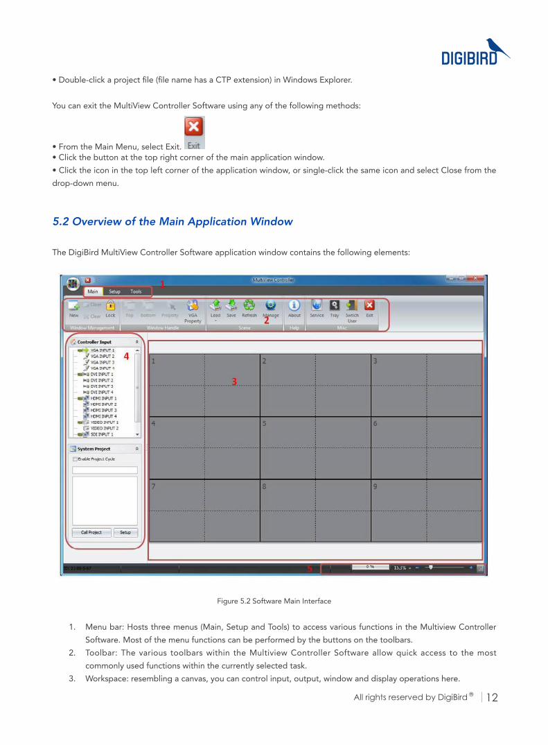
Figure 5.2 Software Main Interface
1. Menu bar: Hosts three menus (Main, Setup and Tools) to access various functions in the Multiview Controller
Software. Most of the menu functions can be performed by the buttons on the toolbars.
2. Toolbar: The various toolbars within the Multiview Controller Software allow quick access to the most
commonly used functions within the currently selected task.
3. Workspace: resembling a canvas, you can control input, output, window and display operations here.
Research & Development, Manufacturer and SalesVideo & Image Processing Expert
All rights reserved by DigiBird ®13 All rights reserved by DigiBird ® 14
4. Taskbar: Each major task within the Multiview Controller Software is represented by drop-down menus in the
taskbar area. To select a task, click the appropriate menu.
The standard set of tasks includes:
a. Input Sources list
b. Scene Design and Control
c. Matrix Switchers control
Fewer tasks may be displayed depending on your settings. For example, when you set up a matrix switcher in the
Menu bar, the matrix switcher control will appear in the Taskbar.
5. Status bar: Shows information about the current status of the Multiview Controller Software.
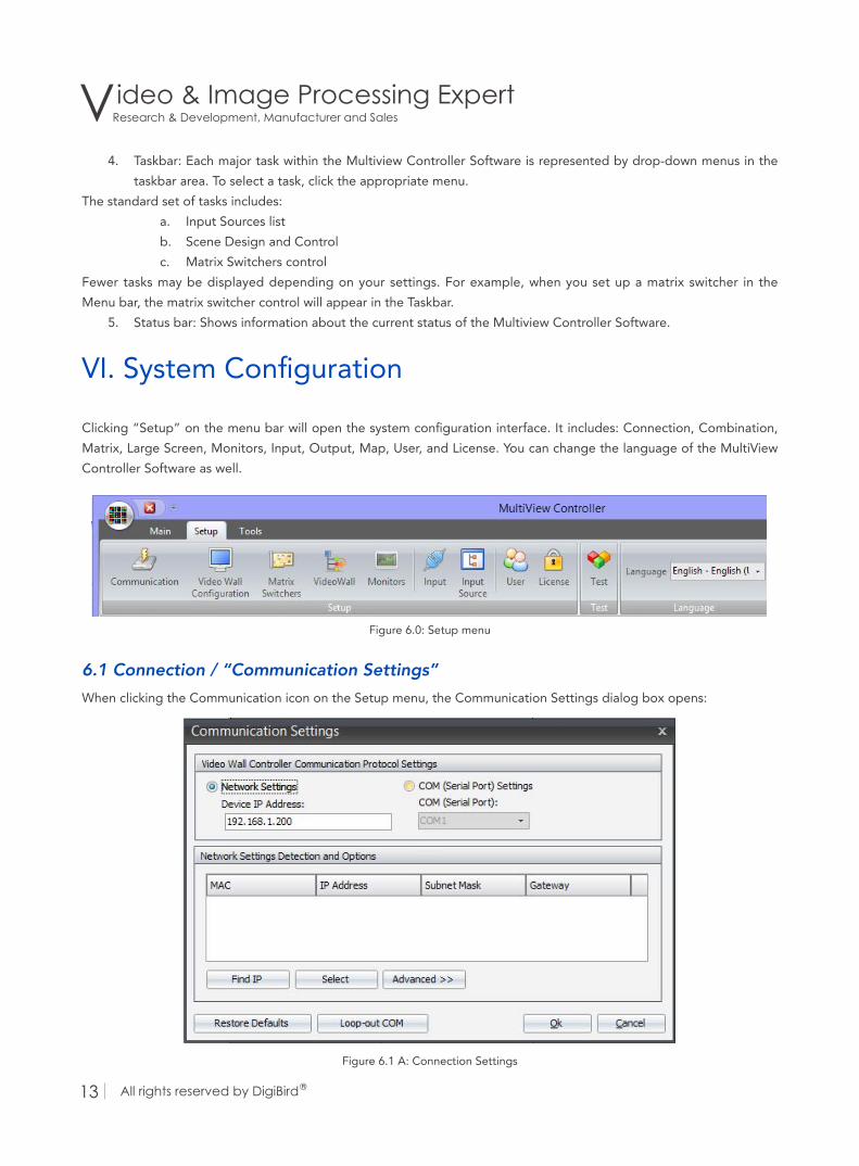
VI. System Configuration
Clicking “Setup” on the menu bar will open the system configuration interface. It includes: Connection, Combination,
Matrix, Large Screen, Monitors, Input, Output, Map, User, and License. You can change the language of the MultiView
Controller Software as well.
Figure 6.0: Setup menu
6.1 Connection / “Communication Settings”
When clicking the Communication icon on the Setup menu, the Communication Settings dialog box opens:
Figure 6.1 A: Connection Settings

All rights reserved by DigiBird ®13 All rights reserved by DigiBird ® 14
You can set up the network connection between the device (DigiBird Video Wall Controller) and the computer and
configure the serial port.
Click the “Output COM” button. The “Output COM” dialog box will appear, as shown in the figure below. You can
then transmit an RS-232 command to a matrix switcher.
Figure 6.1 B: Com Connection Settings
6.2 Video Wall Configuration (Video Wall, input and output configuration)
Using “Video Wall Configuration”, you can configure the video wall, output formats and inputs.
Figure 6.2: Video Wall Configuration menu
6.3 Video wall and output configuration
Click “Video Wall Configuration” on the “Setup” menu. The following dialog box will open:

Research & Development, Manufacturer and SalesVideo & Image Processing Expert
All rights reserved by DigiBird ®15 All rights reserved by DigiBird ® 16
Figure 6.3 A: Video Wall Configuration
1. Drag the slider horizontally to select the desired resolution of each screen.
2. In the physical screen, set the overall horizontal and vertical size of the target display (measured in whole
screens) by clicking the Up and Down Arrows. The maximum wall size available is dependent upon the model.
In the Logical Sub Screen, set the overall horizontal and vertical size of a screen by clicking the Up and Down
Arrows. For example, “horizontal=2 and vertical=2”, means you can open four windows per screen.
3. If you check the box (bottom line is monitor), you can preview and monitor several video wall screens by
clicking the Up and Down arrows. These screens must be located on the bottom line of the video wall.
4. In the screen option, you can choose the refresh rate of the screens by clicking the Up and Down arrows.
5. In the edge width options section, you can adjust mullion compensation by clicking the Up and Down arrows.
Mullion is the frame border area that exists between two displays. This area must be taken into account so
that when an image is spread across two or more displays, the image flow is not distorted.

All rights reserved by DigiBird ®15 All rights reserved by DigiBird ® 16
Figure 6.3 B: Mullion Compensation
6. If there is no entry in the “screen resolution option” that matches the specific signal for your display device,
you can create a new resolution for your display by clicking the “Add” button:
Figure 6.3 C: Resolution Settings

Research & Development, Manufacturer and SalesVideo & Image Processing Expert
All rights reserved by DigiBird ®17 All rights reserved by DigiBird ® 18
Click “OK” to save the changes.
7. Choose the specific resolution, and then click “Advance”. You can now modify its parameters.
Click “OK” to save the changes.
6.4 Input configuration
Click the “Input Option” tab to open the following dialog box:
Figure 6.4: Input Cards Detection
Click “Detect input cards”. The system will automatically detect which input cards have been plugged into the
controller.
6.5 Matrix switcher configuration
Click “Matrix Switchers” in the “Setup” menu. The “Matrix Config” dialog box will appear, as shown below. This
function is used to control third-party matrix switchers with the DigiBird Video Wall Controller’s serial port. Click the
“Setup” button to configure the output serial port of the DigiBird Video Wall Controller:

All rights reserved by DigiBird ®17 All rights reserved by DigiBird ® 18
Figure 6.5 A: Matrix Settings
Figure 6.5 B: Matrix Communication Settings

Research & Development, Manufacturer and SalesVideo & Image Processing Expert
All rights reserved by DigiBird ®19 All rights reserved by DigiBird ® 20
6.6 Video Wall configuration
When you click “Video Wall”, the dialog box shown below will open. There are four ways to turn the large screen (video
wall) on or off by configuring the dialog box, including the output serial port of the DigiBird Video Wall Controller,
serial port, TCP protocol and UDP protocol. By clicking on the associated radio buttons, you can decide when to power
the video wall on and off.
Figure 6.6: Video Wall Settings

All rights reserved by DigiBird ®19 All rights reserved by DigiBird ® 20
6.7 Monitors
Monitor setup is demonstrated below:
Figure 6.6: Monitor Setup
6.8 Input
When you click “Input” on the “Setup” menu, the “Input Options” dialog box opens, as shown in the figure below.
Figure 6.7 A: Input Options

Research & Development, Manufacturer and SalesVideo & Image Processing Expert
All rights reserved by DigiBird ®21 All rights reserved by DigiBird ® 22
The figure reveals that the device has five different source types for input cards, including one VGA input card (Input
channels 1-4), one DVI input card (Input channels 1-4), one HDMI input card (Input channels 1-4), one VIDEO input card
(Input channels 1-2), and one SDI input card (Input channels 1-2).
6.9 Screen Mapping Settings
The corresponding relations between inputs and screens can be adjusted as below:
Figure 6.8: Screen Mapping
VII. The User
The MultiView Controller Software allows different operators to have access to different tasks according to their needs
and responsibilities. This feature helps to prevent end users from being able to make unauthorized changes to the
setup of the DigiBird Video Controller system.
The following table lists the three available access levels and the tasks that are accessible to each level.
TaskAccess Level
Administrator Super User User
Configure, Connection, Combination,
Matrix, Large Screen, User
Management, License, External Tools
YES N/A N/A
Save, set up, manage scenes YES YES N/A
Back up and restore data YES YES N/A
Modify input signals YES YES N/A

All rights reserved by DigiBird ®21 All rights reserved by DigiBird ® 22
Click “User” on the “Setup” menu to open the “User Management” dialog box:
Figure 7.0: Users Setup
VIII. License
Figure 8.0: License Options

Research & Development, Manufacturer and SalesVideo & Image Processing Expert
All rights reserved by DigiBird ®23 All rights reserved by DigiBird ® 24
IX. Language Settings
The MultiView Controller Software currently supports four language packs, including English, Spanish, Russian,
Simplified Chinese and Traditional Chinese. By clicking the drop-down box, you can select the desired language.
Figure 9.0: Language Settings
X. Windows and input signal management
The Workspace is a canvas-like virtual display area where you can design window arrangement and the display content
for your video wall, as shown in the figure below. You can create windows on the workspace by dragging and dropping
input signals from the input list. You can also reset the windows’ properties. The content of each window can be the
same or can differ.
Basic Operation:
• You can select and drag the input source to the workspace.
• The Workspace can be zoomed in and out by scrolling up and down with your mouse or by using the scroll bar
on the workspace.
• By clicking the right mouse button, a popup window will appear. The popup windows may differ, as shown
below.
In this example the video wall configuration is 3×3.

All rights reserved by DigiBird ®23 All rights reserved by DigiBird ® 24
Figure 10.0 A: Video Wall Array
Figure 10.0 B: Windows Settings
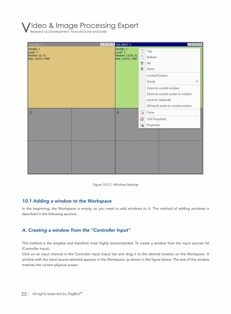
Research & Development, Manufacturer and SalesVideo & Image Processing Expert
All rights reserved by DigiBird ®25 All rights reserved by DigiBird ® 26
Figure 10.0 C: Windows Settings
10.1 Adding a window to the Workspace
In the beginning, the Workspace is empty, so you need to add windows to it. The method of adding windows is
described in the following sections.
A. Creating a window from the “Controller Input”
This method is the simplest and therefore most highly recommended. To create a window from the input sources list
(Controller Input):
Click on an input channel in the Controller Input (input list) and drag it to the desired location on the Workspace. A
window with the input source selected appears in the Workspace, as shown in the figure below. The size of the window
matches the current physical screen.

All rights reserved by DigiBird ®25 All rights reserved by DigiBird ® 26
Figure 10.1 A: Create a Window
Limitation: you can open four windows including four different input sources on a physical screen.
Forcing open a window: if you would like to open a new window on a screen that already occupies a window, you can
click on an input source and simultaneously press the “CRTL” key, and then drag and drop it to the screen. While a new
window will be opened, the original window will still be there, but will be located below in a lower layer (you cannot
see it because the new window overlaps the original window).
B. Creating a window from the “New” button on the Main menu
Click “New” on the “Main” menu. A popup window will appear on the workspace, as shown below. You can then set
the parameters for the new window.
Figure 10.1 B: Window Position

Research & Development, Manufacturer and SalesVideo & Image Processing Expert
All rights reserved by DigiBird ®27 All rights reserved by DigiBird ® 28
10.2 Closing windows
You can close all the windows on the Workspace by clicking the “Clear” button on the “Main Menu”.
The methods of closing a window are described in the following sections.
• Click the “X” button in the top right corner of the screen.
• Click the “Close” button on the “Main Menu”.
• Right-click a window and select the “Close” option.
10.3 Changing Z-order (layers)
Windows may be positioned anywhere on the wall and can be placed to overlap other windows. When windows
overlap they are layered in an order of a user defined priority. The layer of a window determines whether it appears in
front of or behind other windows. A layer is also known as a Z order. Layers are identified by a number and the higher
the number, the further forward the window. For example, a window on layer 3 appears in front of a window on layer 2,
but behind a window on layer 4, as shown in the figure below. The farthest back is layer 0.
Figure 10.3 A: Layering settings
Top optionBy setting a window’s layer to the Top, it will appear on top of all other windows and have the highest priority (Z-order).
Bottom optionSetting a window’s layer to the Bottom means that it will be placed below all other windows and have the lowest
priority (Z-order).

All rights reserved by DigiBird ®27 All rights reserved by DigiBird ® 28
Up option
Clicking “Up” will bring the window up one layer at a time (one Z-order number).
Down option
Clicking “Down” will send the window down one layer at a time (one Z-order number).
Locked position
The MultiView Controller Software has the ability to freeze the location of the window on the video wall.
Locking a specific window is accomplished by the following procedure:
• Right-click on the desired window on the virtual screen.
• Click the left mouse button to select the “Locked Position” operation.
Follow the same procedure above to unlock a window.
Moving a window
To move a window, position the cursor over the window on the virtual screen and then click and drag the window to
the new position.
Grouping windows
The windows can be merged into a group by right-clicking any window and locking it in place. The group (all of the
windows) will be locked. As mentioned, you can use this function to create a high resolution or dynamic background
image.
Windows 1, 2, 3, and 4 belong to group 1; windows 5 and 6 belong to group 2, as shown in the figure below:
Figure 10.3 B: Grouping Windows

Research & Development, Manufacturer and SalesVideo & Image Processing Expert
All rights reserved by DigiBird ®29 All rights reserved by DigiBird ® 30
10.4 Zooming in on the windows
Any window can be set to automatically fill the complete video wall, any single screen on the video wall, or any virtual
screen. Right-click the desired window. The following popup will open:
Figure 10.4: Zooming
Zoom to current window: the selected window will be set to fill a virtual screen.
Zoom to current screen or window: the selected window will be set to fill the current screen or virtual screen.
Zoom to videowall: the selected window will be set to fill the whole video wall.
All inputs zoom to current window: all windows will fill the virtual screens.

All rights reserved by DigiBird ®29 All rights reserved by DigiBird ® 30
10.5 Cropping an input sourceIf you use a source with black bands on top/bottom or left/right, you can crop it. Right click a window and select the
“Set Source Cutting “option. A popup window will then open. Use the Top, Bottom, Left, and Right values to crop your
input.
Figure 10.5: Source Cutting
XI. Scene design and control
A scene means a collection, including the size, position, and contents of one or more windows. You can store and recall
them as needed. Each scene can have a different arrangement of windows and sources. Several scenes can be made
into a project.
11.1 Creating a scene
To create a new scene, you can click the “Save” button on the “Main Menu”:
Figure 11.1: Save Scene

Research & Development, Manufacturer and SalesVideo & Image Processing Expert
All rights reserved by DigiBird ®31 All rights reserved by DigiBird ® 32
11.2 Recalling a scene
The methods of recalling a scene are described in the following sections.
The first method:
Click “Load” on the “Main Menu” and then select the desired scene:
Figure 11.2 A: Read a Scene
The second method:
On the system project menu, select the desired scene and click “Call Project”:
Figure 11.2 B: Call Project

All rights reserved by DigiBird ®31 All rights reserved by DigiBird ® 32
Technical Support
Notices: for additional technical support, please contact DigiBird:
DigiBird LLC.
819 North 49th St. STE 101,
Seattle, WA 98103
www.digibirdtech.com
Tel: 206-639-8941