Wakefield Council Street Design Guide · Street Design Guide Wakefield Council A guide for...
119
A new vision for developing Wakefield District www.wakefield.gov.uk Street Design Guide Wakefield Council A guide for residential, commercial and mixed use development in Wakefield district.
Transcript of Wakefield Council Street Design Guide · Street Design Guide Wakefield Council A guide for...

A new vision for developing Wakefield District
www.wakefield.gov.uk
Street Design Guide Wakefield Council
A guide for residential, commercial and mixed use development in Wakefield district.

Street Design Guide - Supplementary Planning Document
Wakefield Council Local Development Framework - Adopted 18 January 2012

Street Design Guide - Supplementary Planning Document
InformationThe Street Design Guide Document is available to view and download on the Council’s website at:
Copies are also available to view at main libraries and Council offices. If you would like to talk to a highway officer about any aspect of this document please contact Highway Development Control on (01924) 306080, 306023 or 306089.
If you would like an extract or summary of this document on cassette, in large type, in Braille or any other format, please call Highway Development Control on (01924) 306080.
Yorkshire Planning Aid provides a free, independent and professional planning advice service to individuals and groups from within the Yorkshire and Humber region who cannot afford professional fees. The organisation may be able to assist groups and individuals who would like support and advice in order to get involved in this consultation process. Please contact our Planning Advice Helpline on 0330 123 9244 or Email
www.wakefield.gov.uk/ldf
(01924) 306080
Wakefield Council Local Development Framework - Adopted 18 January 2012

1
ContentsPage 2. Status of the Street Design Guide
3. 1. Introduction
5. 2. Preparing Development Proposals
7. 3. Design Guidance
7. 4. Street Types
23. 5. Speed Restraint
26. 6. Vertical Alignment
27. 7. Junction Spacing and Visibility
35. 8. Pedestrian Movement
38. 9. Cycling
42. 10. Designing for Disabled People
44. 11. Car Parking
53. 12. Vehicle Tracking, Servicing and Turning Spaces
55. 13. Emergency Access
55. 14. Landscape Considerations within the Highway
58. 15. Public Utilities
61. 16. Drainage
62. 17. Highway Structures
63. 18. Public Transport
64. 19. Other Requirements
67. 20. Materials and Construction
74. INDEX
APPENDICES
78. A. Supplementary Planning Guidance (SPG7)District Wide Parking Standards
92. B. Adoption Procedures
98. C. Section 278 Procedures
102. D. Structural Procedures
108. E. Street Lighting Procedures
112. F. Drainage Procedures
Street Design Guide - Supplementary Planning Document
Wakefield Council Local Development Framework - Adopted 18 January 2012

Status of the Street Design GuideThis Guide has been produced during 2010/2011, drawing extensively on material contained in a similar Guide published by Leeds City Council, and drawing on local current and intended practice in Wakefield. The October 2011 edition (final version) of the Wakefield document has been approved as a Supplementary Planning Document in the Wakefield Local Development Framework, following extensive public consultation.
The document has now been adopted as an SPD and has formal status in planning matters. It represents the current approach of the Council, as Highway Authority, particularly in interpreting the Government's document, 'Manual for Streets' and 'Manual for Streets 2'.
This document will form part of the Wakefield Local Development Framework which is made up of a number of separate documents produced at different times. The LDF should be read as a whole and decisions about future development must have due regard to all its relevant parts. More information on the LDF is available to view on the Council's website at: www.wakefield.gov.uk/ldf.
2Wakefield Council Local Development Framework - Adopted 18 January 2012

QUALITY OF LIFEIN RESIDENTIAL AREAS
Sense of community
Walkableneighbourhoods
Safe and attractivefor cycling
Bin lorry, deliveryand fire appliance access
Trees, grassy spacesand landscape
Attractive buildings
Place for car
Sun into house/garden
Access for allPlace to play Lifetime homes
Close to goodpublic transport
Opportunities forwork nearby
Natural surveillanceagainst Crime
Local shopsnearby
Public spacesusable/enjoyable
Communal space
Private open space
1.3 "Manual for Streets"(MfS) emphasises the overall importance given to placemaking, and encourages the design of streets based on their function rather than purely the level of traffic carried. These principles are endorsed by the Council, and therefore where appropriate, this Street Design Guide refers to the relevant section of MfS. This guide also provides advice regarding where the Council does not see MfS applying.
1.4 On publication of MfS the previous "Design Bulletin 32" and "Places Streets and Movement" were withdrawn. However, some items from those documents have been included within this Street Design Guide where it was felt appropriate, as otherwise they would be lost as sources of design advice.
1.5 The Guide is intended for use by developers, design teams and others and seeks to stimulate innovative designs that are appropriate for the context, character and location of a site and can be used safely by the travelling public. Designs will be encouraged to incorporate quality approved sustainable materials that are visually attractive, require minimum maintenance, and are in keeping with the specific local character of the area.
3
Street Design Guide - Supplementary Planning Document
Wakefield Council Local Development Framework - Adopted 18 January 2012
1. Introduction1.0 This Street Design Guide for Wakefield is a key
element to delivering high quality residential and mixed development environments in the District and should be used in the context of other national and local planning or design guidance. In particular, it should be read in conjunction with:
Wakefield's current "Residential Design ?Guide";
Advice issued by the Government's ?Communities and Local Government department in relation to 'Delivering well designed homes and high quality spaces' in the context of the Planning Act 2008;
Advice issued by CABE (Commission for ?Architecture and the Built Environment);
City Centre Streetstyle Design Guide - Whilst ?this Street Design Guide is unlikely to have wide application within Wakefield City Centre, the Streetstyle Guide demonstrates the Council's ambitions for the public realm.
1.2 The Street Design Guide aims to add some flexibility in the approach to design as set out in "Manual for Streets" (2007) and "Manual for Streets 2" (2010), and provides specific local guidance to supplement existing national guidance. The Guide supersedes the former West Yorkshire Metropolitan County Council's "Highway Design Guide" (1985).

1.6 The Guide covers the design of the 'highway' in its broadest sense, namely the public space between private dwellings or plots that facilitates all public activity, including but not exclusively the circulation and storage of motorised traffic. To this end the Guide encourages designers to consider 'streets', not just 'roads', and also all the other components that make up the public realm (e.g. signs, cabinets, lighting, landscape, etc). In locations within or adjacent to Wakefield City Centre, appropriate reference should also be made to the City Centre Streetstyle Design Guide.
1.7 Achieving sustainable developments is crucial if the Council is to meet its social, economic and environment objectives. These relate to sustainability in its widest sense, not only transport accessibility, so that sustainable materials, drainage and other elements are equally important.
1.8 A street caters for the movement of pedestrians and cyclists, vehicular traffic, servicing and access arrangements as well as less dynamic functions such as car parking and landscape features. Well designed streets should accommodate all functions and purposes (including provision for utility services, street lighting and drainage), and their inter-relationship should be considered from the outset. However, the emphasis should be on "people movement" based on the following hierarchy of consideration, with the needs of the disabled, the elderly, and children to be taken into account for all modes:
User Hierarchy
Consider First Pedestrians CyclistsPublic Transport UsersService Vehicles (including emergency services, waste, etc)
Consider Last Other motor traffic
1.9 Walking and cycling are important modes of transport, offering a more sustainable alternative to the car, making a positive contribution to the overall character of a place, public health and to tackling climate change through reductions in carbon emissions.
1.10 The Guide should be used for any residential development; whether creating new highway or for development on existing streets. It also gives guidance for mixed-use developments, and for industrial/commercial schemes.
1.11 Designers will be expected to demonstrate within their submission documents (Transport Statement/ Transport Assessment and Travel Plan, Design & Access Statement) how their scheme complies with the principles set out in both this Guide, together with the Council's wider aspirations for quality environments.
1.12 Section 2 of this Guide sets out the Council's requirements for any development proposals, and the documentation required to support a Planning Application.
1.13 Section 3 contains various design guidance.
1.14 Section 4 describes the four residential Street Types used within this guide, and Sections 5 to 19 contain detailed technical guidance on various aspects of highway and street design.
1.15 Section 20 covers guidance on materials and construction details.
4Wakefield Council Local Development Framework - Adopted 18 January 2012
Street Design Guide - Supplementary Planning Document

2. Preparing Development Proposals
2.1 Designers and developers are advised to have pre-application discussions with Local Authority Officers at an early stage in the design process. Initial contact should be through Planning and Highway Development Control Officers, who will then consult with other Officers as required (e.g. Transportation, the Section 38 Team, Bridges Section, Drainage, PRoW etc). Adequate preparatory work by prospective applicants will assist in ensuring that officers' input is effectively used.
Analysis
Concept
Scheme
Detail
Recognise the needs of those with physical ?difficulties, including visual, hearing and other impairments;
Help create quality environments in which to ?live, work and play;
Include features in special areas where extra ?care is required - such as at schools.
2.3 The Council is prepared to consider alternative proposals in some areas. However, where a design or feature is proposed that does not strictly accord with design guidance, advice, or other parameters in this Guide, the proposer of the amendment is required to give adequate justification, for consideration by the Council.
2.4 The amendment will only be allowed if it fulfils all of the following requirements:
Does not result in a lower standard of road ?safety;
Does not result in adverse or differential ?effects on selected groups of people, primarily the disabled (mobility impaired, blind/partially sighted, hearing impaired) children, and the elderly;
Does not diminish the convenience and ?suitability of facilities for pedestrians, cyclists and public transport users;
Does not diminish the sustainability of the ?design under any of the sustainability aspects highlighted in the document;
Does not contravene Policies in the Local ?Plan Development Framework unless there are material considerations to suggest otherwise. In particular Core Strategy Policy CS4, CS9, CS10, and CS14. Development Policies D9, D11, D14, D15, D18 and Central Wakefield Area Action Plan Policies CW2, CW9, CW10, CW11;
Does not lead to a reduction in quality of ?public realm, or the durability of infrastructure;
Does not lead to a deterioration in any other ?sustainability consideration;
Does not increase the opportunity to commit ?crime and reduce community safety.
2.2 The guidance set out in this document is intended to assist in the design of development layouts that provide safe movement for all street users, including pedestrians of all ages, cyclists, users of public transport, cars, service vehicles, and others. Therefore, designers should select and assemble appropriate design elements to:
Provide street layouts that meet the needs of ?all users and do not allow vehicles; particularly service vehicles, to dominate;
Create an environment that is safe for all street ?users and in which people are encouraged to walk, cycle, use public transport, and feel safe doing so;
5
Street Design Guide - Supplementary Planning Document
Wakefield Council Local Development Framework - Adopted 18 January 2012
2.5 There is a principle of 'no trade-offs' in assessing amendments. That is, a positive contribution on one factor can not be traded-off against a negative effect elsewhere. Amendments which increase sustainability or the design's user-friendliness for selected groups of people, without detriment to others, will be viewed positively. Amendments that are proposed primarily for reasons of minimising costs will only be considered if all of the above requirements are satisfied. All circumstances will be considered on their own merits.
2.6 Development proposals should be accompanied by various supporting documentation as required by the Council's Planning Department. In addition, certain highway and transport reports may be required as follows:-
i) Design and Access Statement - This will set out the main placemaking, design and sustainability elements of the scheme, and should demonstrate how it complies with the objectives and requirements of this guide. Areas to be offered for adoption should be clearly identified. Such a Design Statement will be required for all developments, although clearly a smaller scheme will require a briefer statement than a large development. Advice on the preparation of these statements has been produced by CABE.
ii) Transport Assessment - Developments over 80 dwellings (or others within Appendix B of the DfT's "Guidance on Transport Assessment" (GTA)) will normally require the preparation of a full Transport Assessment (TA). The scope of the TA should be agreed in advance with the Local Authority and should be in accordance with current national guidelines. It should assess both traffic impact and transport sustainability, including an assessment of how well a scheme addresses the needs of pedestrians of all ages, cyclists and non-motorised users.
iii) Transport Statement - Developments of between 50 and 80 dwellings (or others in the DfT's guidance) will normally require an abbreviated form of a TA, addressing certain limited issues that are relevant to the particular scheme. These will usually be access to pedestrian, cycle and public transport facilities. The scope of the Transport Statement should be agreed in advance with the Local Authority, and should cover accessibility as well as impact.
Iv) Travel Plan - Certain developments, as identified by the GTA, will also require the provision of a Travel Plan, to specify the measures that will be taken to encourage the use of non-car modes of transport. The Plan content should include how it will be promoted and managed, what targets will be applied, the measures that are promoted to achieve the targets, and what action will be taken if targets are not being achieved. Any Travel Plan ideally will need to be approved prior to Planning Permission being granted. Guidance on the preparation of Travel Plans will be contained in the draft SPD on Travel Plans, being prepared in 2012.
v) Safety Audit - Any scheme/ development which requires a S278 Agreement shall undertake an independent Stage One Safety Audit in accordance with HD 19/03. These look at highway works from the perspective of the end user, and specifically aim to identify any safety issues that may need to be addressed. A Stage 1 Safety Audit should be submitted with the planning application. Where relevant, Safety Audits should include an assessment of the likely level of risk. Subsequent Stage 2, 3 and 4 Audits will also be necessary.
6Wakefield Council Local Development Framework - Adopted 18 January 2012
Street Design Guide - Supplementary Planning Document

3. Design Guidance
SPG2 Residential Design Guide
Safer Places
3.1 The Supplementary Planning Guidance (SPG2) sets out, for intending developers in Wakefield District, the standards and guidelines against which planning applications for residential development will be considered by the Local Planning Authority. It is the Council's intention to use SPG2 to encourage an innovative yet flexible approach to new development. The objective has been to increase the level of amenity of individual householders by creating more sensitive, interesting and exciting living environments. SPG2 will be revised within the context of the Local Development Framework and the document will contain new advice on place making. It will continue to be the main reference point for overall guidance on residential development.
3.2 The layout of a residential area can have a significant impact on crime against property (homes and cars) and pedestrians. The Crime and Disorder Act requires local authorities to exercise their function with due regard to the likely effect on crime and disorder. To ensure that crime prevention considerations are taken into account in the design of layouts, it is important to consult Police Architectural Liaison Officers as advised in "Safer Places".
3.3 To ensure that crime prevention is properly taken into account, it is important that the way in which permeability is provided should be given careful consideration. High permeability is conducive to walking and cycling, but can lead to problems of anti social behaviour if it is only achieved by providing routes that are poorly overlooked, such as rear alleyways.
4. Street Types
General Approach
4.1 To achieve high quality and varied residential spaces, it is necessary to consider options in highway design, with due regard to current statutory regulations, whilst still maintaining levels of road safety, and the other requirements set out in paragraph 2.4 of Manual for Streets.
4.2 Guidance that contains too many unnecessary rules and restrictions can inhibit innovation, preventing schemes from reflecting local character and distinctiveness.
4.3 However, this approach also places greater responsibility on the Design Team to demonstrate that the proposals will operate safely and satisfactorily, are maintainable and sustainable, and to justify the design choices that have been made.
4.4 This Street Design Guide covers the following situations:
a) Residential streets
b) Private drives
c) Industrial or commercial developments
d) Mixed-use schemes
4.5 The Council welcomes discussions with Developers who are interested in including Home Zones within their development. Proposals for home zones will need to take account of the latest national guidance, which is currently the DfT's "The Quiet Lanes and Home Zones (England) Regulations" published in August 2006, and should be in accordance with "Home Zones, Design Guidelines" published by the Institute of Highway Incorporated Engineers.
7
Street Design Guide - Supplementary Planning Document
Wakefield Council Local Development Framework - Adopted 18 January 2012

Residential Streets
Street Hierarchy
4.6 Within new residential areas, streets need to accommodate various types of movement in a convenient and safe manner. The needs of motorised traffic must be balanced with those of pedestrians of all ages and abilities, cyclists and users of public transport. The design of the street needs to be appropriate for the function of that part of the street, as the function may vary along its length. Streets should also be designed so that they form an attractive environment, responding to their context. To achieve this it is essential that new residential streets form a natural hierarchy that is clear and legible to all users who share the same space.
4.7 This hierarchy should provide an understandable transition from the external distributor roads where motor vehicular space requirements may be more dominant, to residential streets (covered by this Design Guide) where the needs of pedestrians and other non-car users are of greater importance.
4.8 Linked streets are encouraged to allow greater connectivity and accessibility by foot, wheelchair and cycle, and to avoid layouts purely based on culs-de-sac. However care is needed to avoid through traffic using a street as a short cut, and appropriate measures will be required to minimise the domination of the street by inappropriate through traffic and not to facilitate crime.
8
4.9 The four adoptable residential street types set out below have been devised to maximise the overall range of design choices, which are possible within each category, to enable the overall adopted "corridor" (including carriageways, footways, verges and other areas) to reflect and enhance the overall design, rather than control it:
Street Type 1 Connector Street
Street Type 2 Local Residential Street
Street Type 3 Shared Surface Street
Street Type 4 Home Zone
Note:This street type numbering system is not intended to match the current "Roads and Street Works Act" (RASWA) category numbers.
Wakefield Council Local Development Framework - Adopted 18 January 2012
Street Design Guide - Supplementary Planning Document

9
4.10 If there is the possibility that a street will serve further properties in the future, for instance if there is an adjacent allocated site which is likely to be developed (and accessed through the first site) then the streets should be designed to the appropriate standard, or be capable of being altered in the future. No "ransom strip" or other gap should be left between the adopted highway and the site boundary in order to provide a durable and 'future proof' street layout.
4.11 Whilst some form of street hierarchy is required in order to construct a network, which is understandable for users, "Manual for Streets" (MfS) warns against the rigid application of a hierarchy based exclusively on vehicular movement. An alternative approach is proposed (MfS paragraph 2.4) based on a wider consideration of the relative status of Place and Movement. Hence, a street within any particular street type may need to be designed differently in the vicinity of shops, bus nodes, adjacent to play areas, etc.
4.12 Therefore, whilst the table below takes the number of dwellings served from a street as a starting point, the subsequent choice of design elements should reflect the wider function of the street using a similar assessment of both the Place and Movement requirements.
Summary of Residential Street Types
Type
1
2
3
4
Title
Connector Streets
Local Residential Streets
Shared Surface Streets
Home Zones
Pedestrian provision
Segregated
Segregated
Shared
Shared
Potential max no. of dwellings
700
200
Any development generating up to 100 vph (2 way flow) in the peak hour
Any development generating up to 100 vph in the peak hour
Design speed
20-25mph
20mph
15mph
10mph
Speed limit
30mph
20mph *
20mph *
20mph *
* 20mph speed limit discretionary - may not be required for suitable designs
4.13 In relation to design speed, MfS paragraph 7.4.2 recommends a maximum of 20mph. Within the local context set out in this Street Design Guide, it is considered that a design speed of 25mph would be appropriate for many Type 1 Connector Streets, although there are also situations where 20mph would be more relevant. Therefore, once again the function of the street needs to be taken into account when deciding on the optimum design speed. Designers will be required to demonstrate how proposed street layouts will achieve the selected design speed in practice.
4.14 Whilst streets must be able to accommodate service vehicles - essential for deliveries of goods, refuse collection and maintenance, they should not over dominate the layout. Whilst there are specific requirements given later in this Guide, the use of computer-aided tracking will be essential in demonstrating practical and safe servicing operations. Preference is given to layouts which avoid the need for reversing.
4.15 The lowest point of any adoptable carriageway should be 600mm above the 1 in 100 year flood level. If there are justifiable reasons why this level may not be achievable in any particular circumstance, this matter must be discussed with the Council.
Street Design Guide - Supplementary Planning Document
Wakefield Council Local Development Framework - Adopted 18 January 2012

10
Street Type 1 (Connector Streets)
4.16 These are the main streets that provide structure for new residential development and connect it to the surrounding urban fabric and highway network.
4.17 Connector Streets can provide a transition between the surrounding major roads and the more pedestrian dominated Local Residential Streets (Type 2). They provide the primary vehicular access to the area, and link with other street types within the new development to form the back-bone of a permeable network of streets for pedestrians and cyclists. It is likely that this street type would also carry the majority of bus traffic through any new development.
4.18 Using a residential street as a bus route need not require restrictions on direct vehicular access to housing. Detailed requirement for streets designed as bus routes can be determined in consultation with local transport operators.
Examples of Type 1 connector streets from new developments.
Wakefield Council Local Development Framework - Adopted 18 January 2012
Street Design Guide - Supplementary Planning Document

11
4.19 To be acceptable for adoption by the Highway Authority, they should be designed to comply with the following ranges of requirements:
Type 1: Connector Streets
I) Potential max number of dwellings
ii) Number of vehicular entry/exit points for the site as a whole
iii) Design speed
iv) Carriageway width
v) Footway width
vi) Verge width
vii) Length between speed restraint features
viii) Minimum forward visibilities
ix) Minimum centreline radius
x) Direct vehicular access
700
See Para 4.20.
20 - 25mph (except at particular locations, such as outside schools, when a design speed of 20mph is required).
5.5m min - 6.75m if a bus route. Width is dependent on type of traffic, percentage of large vehicles, whether a bus route, plus other design considerations, tracking of vehicle movement, with widening on bends or elsewhere where necessary (see section 12).
2m absolute minimum, to increase to 3m or more in areas of identifiably higher levels of pedestrian activity (adjacent to schools, shops, bus stops, railway stations, etc) or if shared with cyclists.
Minimum 1m width on streets over 300 dwellings.
60 or 100m (see Section 5) dependent on design speed.
25 or 33m dependent design speed (see section 7). Visibilities significantly above these levels should be avoided to deter excessive speeds.
35m (see also section 12).
Acceptable if it can be demonstrated that it would not cause a highway problem.
- For vertical design requirements see section 6- For junction requirements see section 7- For drainage requirements see section 16- For materials/construction requirements see section 20- For other requirements refer to the "Contents" or "Index" Pages
Street Design Guide - Supplementary Planning Document
Wakefield Council Local Development Framework - Adopted 18 January 2012

12
4.20 For developments of over 300 dwellings, at least two points of vehicular entry/exit are preferred to maximise accessibility, connectivity, and efficient operation in emergencies, and so culs-de-sac will not normally be permitted, unless in exceptional circumstances. Although the provision of more than one access is encouraged, where this is not possible a single vehicular access may be accepted providing the internal network forms a loop, with the shortest possible connection of suitable width between this loop and the point of access.
4.21 For Connector Streets serving over 300 dwellings, a verge or hard margin between the footway and carriageway should be provided to increase separation between vehicles and pedestrians. Tree planting in this zone will increase perception of this separation, and will "green" the street environment, but should not be located in areas which could affect safety, such as visibility splays, or be subject to damage by larger service vehicles.
Examples of typical local residential streets from new developments.
Street Type 2 (Local Residential Streets)
4.22 These are the general streets within residential areas, which carry a wide range of movement types and provide the main setting for new homes, allowing direct access to individual dwellings. They will be used by service vehicles, and the requirements of these vehicles will need to be accommodated, although should not over dominate. Layout and on-street parking will need to be appropriately designed and controlled.
4.23 Local Residential Streets may provide access (depending on the scale of development) directly onto the existing external network, or may first access onto a Connector Street (Type 1) before reaching the main road network. These streets are unlikely to carry large volumes of traffic or bus routes and the geometry requirements shift as a result, allowing tighter urban streets and the potential for increased on-street parking, when designed into the street layout.
Wakefield Council Local Development Framework - Adopted 18 January 2012
Street Design Guide - Supplementary Planning Document

13
Street Design Guide - Supplementary Planning Document
Wakefield Council Local Development Framework - Adopted 18 January 2012
4.24 To be acceptable for adoption by the Highway Authority, Local Residential Streets should be designed to comply with the following ranges of requirements:
Type 2: Local Residential Streets
I) Pdwellings
otential max number of
ii) Number of vehicular entry/exit points for the site as a whole
iii) Design speed
iv) Carriageway width
v) Footway width
vi) Maximum length between speed restraint features
vii) Mvisibilities
inimum forward
viii) Mradius
inimum centreline
ix) Direct vehicular access
200
Up to 50 and 200 dwellings:Culs-de-sac being avoided if possible. If absolutely necessary, they should have a maximum length of 200m. Turning facilities should be provided if the cul-de-sac is longer than 45 metres, and if the length is greater than 100m then additional turning facilities will be required.
20mph
Min width 5.5m although width can vary to respond to built form, vehicle tracking movements and public spaces and if on-street car parking, turning from accesses, plus widening on bends or elsewhere where necessary (see section 12).
2m minimum (subject to level and type of pedestrian usage or if shared with cyclists).
60m (see section 5)
25m (see section 7). Visibilities significantly above this level should be avoided to deter excess speeds.
20m or based on vehicle tracking requirements (see also section 12).
Allowed
- For vertical design requirements see section 6- For junction requirements see section 7- For drainage requirements see section 16- For materials/construction requirements see section 20- For other requirements refer to the "Contents" or "Index" pages

14Wakefield Council Local Development Framework - Adopted 18 January 2012
Street Design Guide - Supplementary Planning Document
Street Type 3 (Shared Surface Streets)
4.25 This street type can be used on streets where the volume of motor traffic can be up to 100vph (2 way peak hour flow). They have shared surfaces with very low vehicle speeds, which should be self-enforcing through good design. Pedestrians can safely share the whole street with vehicles, however the designated pedestrian routes are available for more vulnerable pedestrians, e.g. elderly people, disabled people and children. Visitor parking (1 space per 4 dwellings) should be provided in designated areas.
4.26 To be acceptable for adoption by the Highway Authority, Shared Surface Streets should be designed to comply with the following ranges of requirements:
Type 3: Shared Surface Streets
I) Pdwellings
otential max number of
ii) Number of vehicular entry/exit points for the site as a whole
iii) Design speed
iv) Highway width
v) Carriageway width
vi) Maximum length between speed restraint features
vii)visibilitiesMinimum forward
viii)radiusMinimum centreline
ix) Direct vehicular access
Up to 100 vehicles (2 way) in peak hour (approx 125 dwellings)
Up to 50 dwellings:Single access point acceptableBetween 50 and 125 dwellings:Cul-de-sacs should be avoided where possible. Turning facilities should be provided if the cul-de-sac is longer than 45 metres, and if the length is greater than 100m then additional turning facilities will be required.
15mph
Variable
4.1m although width can be designed to respond to built form, vehicle tracking movements and public spaces and if on-street car parking, visitor parking, turning from accesses, plus widening on bends or elsewhere where necessary for service vehicles (see section 12).
40m (see section 5)
23m (see section 7). Visibilities significantly above this level should be avoided to deter excess speed.
Based on vehicle tracking requirements of service vehicles in current use (see also section 12).
Allowed
- For vertical design requirements see section 6- For junction requirements see section 7- For drainage requirements see section 16- For materials/construction requirements see section 20- For other requirements refer to the "Contents" or "Index pages
4.27 Careful consideration needs to be given to how and where car parking is provided (also see section 11). Visitor parking should form part of the prospective adoptable layout.
4.28 It is required that these streets are block paved and surface materials are chosen to delineate the functions of the different parts of the highway.

15
Street Design Guide - Supplementary Planning Document
Wakefield Council Local Development Framework - Adopted 18 January 2012
Examples of typical Type 3 shared surface streets from new developments
Street Type 4 (Home Zones)
4.29 Home Zones are residential streets in which the road space is shared between drivers of motor vehicles and other road users, with the wider needs of residents (including people who walk and cycle, the elderly and children) in mind. The aim is to change the way that streets are used and to improve the quality of life in residential streets by making them places for people not just for traffic. Changes to the layout of street should emphasise this change of use, so that motorists understand and accept that they should give informal priority to other road users.
4.30 Motorists should feel that they have left the normal highway and have entered an area where they can expect to find people who are using the whole of the street. In essence, the Home Zone should make motorists feel they are guests in a pedestrian environment, and should drive accordingly.
4.31 Home Zones may consist of shared surfaces, indirect traffic routes, areas of planting, and features to encourage the use of the street. "Gateways" and regulatory signing will be needed to mark the limits of the area. In designing home zones full consideration of the needs of disabled people should be taken into account.
The recommendations included in "Designing for Disabled People in Home Zones", (JMU Access Partnership 2007) should be followed to ensure that the needs of disabled people are properly considered. Designated pedestrian routes through the home zone of 2m minimum width should be provided which could be provided using a 30mm kerb upstand with flush crossing points and tactile paving where required. Some colour / shading difference is required to identify the pedestrian route. Consideration should be given to way finding at the front and rear of the pedestrian route.
4.32 Design guidance and other information on Home Zones, including links to related websites, is available through the Institution of Highway Incorporated Engineers at www.ihie.org.uk and www.homezones.org.uk.
4.33 Procedural guidance is set out within the Department for Transport's Circular 02/2006 "The Quiet Lanes and Home Zones (England) Regulations 2006". Home Zones shall be used only where traffic flows are no more than about 100 peak hour vehicle movements, so the number of dwellings will vary with the location and nature of the development. Typically, this traffic flow equates to around 150 dwellings.

16Wakefield Council Local Development Framework - Adopted 18 January 2012
Street Design Guide - Supplementary Planning Document
4.34 The statutory process for the designation of a Home Zone and the making of the associated use and speed orders requires that there is consultation with local groups, and in particular the residents of the area. While this does not present a problem with Home Zones in existing streets, there is an apparent difficulty with new build developments in that streets are normally well on the way to being built when residents begin to move in. In this case, new purchasers will require information with sale details.
4.35 Therefore, it is recommended that an information pack be given to all purchasers, setting out general information on Home Zones, together with the key proposals for the site
(including a draft wording of the use and speed orders) explaining the way in which the streets will be managed and maintained.
4.36 Purchasers will then be asked to sign this document, stating that they have understood and agree in principle with the Home Zone proposals. Once the streets are open to the public, the Council will carry out the formal consultation process to enable the Home Zone to be designated and the Orders made at the Developer's expense.
Type 4: Home Zones
I) Pdwellings
otential max number of
ii) Design Speed
iii)speed restraint features Maximum length between
iv) Design Speed
v) Carriageway width
vi) Minimum forward visibilities
vii)have a buffer zone between the properties and areas shared with vehicles. This will allow the provision of street equipment.
Residential units should
viii)be designed into the scheme
On-street parking should
ix) Cnormally be acceptable
ul de sacs will not
Home Zone streets should have traffic flows of up to 100 two-way vehicular movements in the weekday evening peak hour.For further information see DfT Guidance " Home Zone Guidelines.”
10mph
30m
10mph
Width can be designed to respond to built form, vehicle tracking movements and public spaces and if on street parking, turning from accesses is to be accommodated plus widening on bends or elsewhere where necessary for service vehicles (see Section 12).
23m (see section 7). Visibilities significantly above this level should be avoided to deter excess speeds.
Based on vehicle tracking requirements of service vehicles in current use (see also section 12).
Allowed
For all other design requirements refer to the DfT / IHIE Design Guidelines, and discuss specific circumstances with the Council.

17
Street Design Guide - Supplementary Planning Document
Wakefield Council Local Development Framework - Adopted 18 January 2012
Example of completed Home Zones
4.42 Swept path analysis is used to determine the space required for various vehicles and is a key tool for designing carriageways for vehicular movement within the overall layout of the street. The potential layouts of buildings and spaces do not have to be dictated by carriageway alignment.
4.43 Layouts using swept path analysis (vehicle tracking) often proves beneficial in determining the street and how vehicles will move within it. Layouts designed using this approach enable buildings to be laid out to suit the character of the street, with footways and kerbs helping to define and emphasise spaces. Designers have the freedom to vary the space between kerbs or buildings. The kerb line does not need to follow the line of vehicle tracking if careful attention is given to the combination of sightlines, parking and pedestrian movements.
4.37 Streets designed to Home Zone standards will only be accepted if Home Zone designation is proposed and is realistically achievable.
4.38 To be acceptable for adoption by the Highway Authority, Home Zones should be designed to comply with the following requirements.
4.39 The design of new streets or the improvement of existing ones should take into account the functions of the street and the type, density and character of the development. The ease, and hence the speed, with which vehicles may move along carriageways depends in part upon the tolerances available both between vehicles and between vehicles and kerbs. On the external highway network where ease of traffic flow is of high priority and where drivers will normally expect to be able to proceed at speeds of over 37mph, carriageway widths need to be in accordance with the recommendations given in the Design Manual for Roads and Bridges.
4.40 On residential streets however, where traffic flows are light and where journeys are starting or ending, drivers may be expected to accept smaller tolerances consistent with the aim of restraining vehicle speeds and encouraging careful driving.
4.41 Whether or not smaller tolerances will cause unacceptable delay, reduce safety, or result in damage to footways and verges, will depend upon the types and volumes of traffic, the design of the carriageway surrounds and the distances over which drivers have to proceed. Such factors may vary considerably within a layout. The tolerances provided by various carriageway widths are set out below. They are not necessarily recommendations and developers are expected to discuss their requirements with the Local Planning Authority.
Carriageway Widths

18Wakefield Council Local Development Framework - Adopted 18 January 2012
Street Design Guide - Supplementary Planning Document
4.44 A 5.5m width is the typical minimum width of adopted highways and allows all vehicles to pass each with ease. Given the infrequency of large vehicles on residential streets, this width is sufficient to cope with residential traffic. Where large vehicles such as pantechnicons are allowed access, passing places may be required. The carriageway width required between passing places will then depend upon the combinations of vehicle types expected; the frequency with which vehicles may meet each other and the delay that may be caused to traffic movement. These factors may be expected to vary with traffic volumes and carriageway width should allow for pedestrians, cyclists, on street parking and servicing.
4.45 At 4.8m wide, the carriageway will allow a wide car to pass a large service vehicle such as a pantechnicon.
4.46 At 4.1m wide the carriageway will be too narrow for large service vehicles such as pantechnicons to pass vehicles other than cyclists. It does however allow wide cars to pass each other with a tolerance of 0.5m on a straight section. Hence, while being restrictive on the movement of large vehicles, a width of 4.1m will still provide two-way flow for the majority of residential traffic. Below 4.1m, the carriageway will be too narrow for private cars comfortably to pass each other except at very low speed and may be uncomfortable for cyclists in conjunction with large vehicles. Widths of less than 4.1m therefore should be regarding as catering only for single-file traffic. Bends require a greater width to accommodate the swept path of larger vehicles.
4.47 The choice of width below 4.1m will depend largely upon the frequency and ease with which cyclists and cars may need to pass each other.
2750
4100
4800
5500
Example of what various carriageway widths can accommodate. They are not necessarily recommendations.

19
Street Design Guide - Supplementary Planning Document
Wakefield Council Local Development Framework - Adopted 18 January 2012
Private (Non-Adopted) Streetsor Drives
4.48 Any development serving more than 5 houses (or an existing Private Street which will serve more than 5 dwellings after completion of the development) should be laid out to an adoptable standard and be able to be offered for adoption. The Local Authority will not normally adopt developments of 5 dwellings or less of any type.
4.49 Schemes with appropriate layouts may be considered acceptable to be served by private driveways under certain specific conditions, which are summarised below:
I) The developer must agree with the Local Authority at an early date the acceptability of the principle of the roads remaining private.
ii) The developer must provide details of the long-term maintenance programme for the highway infrastructure.
iii) The developer must provide details of how the entrance to the private development is to be defined on site.
iv) The highway infrastructure must be designed and constructed to adoptable standards in all respects with the exception of the specific agreed reasons as to why the roads are to remain private.
4.50 Whilst Private Streets or Drives can allow the introduction of a higher standard of materials, lighting, etc than may be achievable with an adopted street, the following potential implications should be taken into account:
Future maintenance liabilities;?
Public liabilities;?
Street cleansing;?
Drainage;?
Public lighting would not be installed;?
The Local Authority would have no powers ?under the Highways Act;
The Police would have no powers to remove ?obstructions.
4.51 A Private Drive serving 5 houses or less should be 5 metres wide for a minimum length of 5 metres, if access is to be taken from a Type 1 Street or a more major route to allow two way passing (subject to tracking). Carriageway widths thereafter should be designed to respond to built form and operational requirements (see para 4.39 - 4.47 and Section 13). No footway or service margin is required, with services being located within the driveway. The horizontal alignment and any need for passing places are based on practical requirements and vehicle tracking where necessary. The requirements for a refuse vehicle to be able to get within 25 metres of all drive-ends or communal storage locations (section 12.6) and for a fire tender to get within 45 metres of all dwelling entrances (section 13.3) need to be considered, and on-site turning facilities provided where carry / pumping distances are exceeded.
4.52 Private Drives must incorporate adequate visitor car parking provision in addition to private curtilage parking.
4.53 Any gates should be set 5 metres back from the adopted highway boundary.
4.54 Such areas will by their nature be more intensively focused towards vehicular movements than residential areas, given the volume and type of traffic expected to use these streets. It will still be required to assess likely needs of other street users and every situation will still be assessed on its own merits. Particular consideration will be required regarding HGV/cyclist interaction. Direct, safe and convenient pedestrian routes should be provided to public transport stops.
4.55 Industrial roads are categorised as Major or Minor, with the same layout standards being applicable in each case. The only real difference is the likely number of Heavy Goods Vehicles (HGV's) and therefore the construction details vary.
Industrial Developments

20Wakefield Council Local Development Framework - Adopted 18 January 2012
Street Design Guide - Supplementary Planning Document
Where a Minor Industrial Road is intended to serve a mainly B1 office development (with a very low number of HGV's) there may be flexibility to vary certain requirements (e.g. radii and turning facilities).
4.56 Major Industrial Roads may serve industrial or commercial developments of up to 20 Hectares. Above this level, roads should be designed in accordance with the Design Manual for Roads and Bridges. Commercial vehicles in residential areas are obviously undesirable, and for this reason, the design of a large scale industrial estate should try to produce a layout which is self-contained and which segregates industrial from local/residential traffic. It should, however be acknowledged that pedestrian and cycle movements are likely to be just as numerous on industrial estate roads as people travel to their place of work.
4.57 In principle mixed use schemes will be encouraged, and where a mixed use scheme has been accepted by the Local Authority as being appropriate, then paras 4.71 - 4.74 should be referred to for design guidance.
4.58 Small scale direct individual access is not to be encouraged on Major Industrial Roads, and a proper hierarchy should be used within an estate so that this form of access is taken from a Minor Industrial Road.
4.59 Minor Industrial Roads may serve industrial or commercial developments of up to 8 hectares (or an industrial building with a gross floor area of 40,000 square metres), and direct frontage access to individual premises is allowed.
4.60 To be acceptable for adoption by the Highway Authority, an Industrial Road should be designed to comply with the following requirements:
Industrial Roads
I) Design speed
ii) Carriageway width
iii) Footway width
iv) Mspeed restraint features
aximum length between
v) Mvisibilities
inimum forward
vi) Minimum centreline radius
25mph
Minimum of 7.3m with widening on bends or elsewhere (see section 12) or to accommodate right turning at junctions.
2m minimum (on each side of road) unless shared by cyclists.
120m (see section 5)
33m absolute minimum (see section 7)
35m (see also section 12)
- For vertical design requirements see section 6- For junction requirements see section 7- For drainage requirements see section 16- For materials/construction requirements see section 20- For other requirements refer to the "Contents" or "Index" pages

21
Street Design Guide - Supplementary Planning Document
Wakefield Council Local Development Framework - Adopted 18 January 2012
4.61 Some developments propose the formation of small groups of industrial units designed for occupation by either one or two man operations.
4.62 The function of these units is to provide a purpose-made "industrial nursery" for businesses, from which a small company can grow and become established. Once this purpose is fulfilled, it is expected that larger premises will be needed by the company, and on relocation of the business, the nursery unit may then be relet.
4.63 It is usual for the industrial units to be up to approximately 150m² in floor area, and generally of a system built construction, sited around a central turning area. Each unit has its own forecourt which acts as both an unloading/loading area and as a casual car parking space. Where additional staff car parking is required, this is normally provided in a communal area, conveniently located adjacent to the turning head. In order for this Industrial "Courtyard" to function properly, a minimum of two staff car parking spaces must be provided to each unit.
4.64 The shared turning head shall be a minimum of 25m radius to enable either a 10m rigid or 16.5m articulated vehicle to turn clear of the unit forecourts. Turning facilities can be designed based on vehicle tracking movements.
4.65 Each unit shall have a forecourt of minimum depth 10m, and a 600mm overhang strip shall be provided around the extent of the adoptable or private industrial road. Where units of a greater floor area are proposed, forecourt depths must be increased to accommodate the associated larger vehicles, expected to visit the development. The table below indicates the Unit Floor Area to Forecourt Depth requirement.
4.66 Where a definite pedestrian movement is created either from the existing highway into the site, or within the courtyard (from say communal car park toilet block to units) a separate footway system shall be provided.
Floor Area Industrial Unit (m²)
Up to 50 7
51 to 150 10
150 and above 16.5
Forecourt Depth (m)
4.67 Private areas such as car parking bays and forecourts shall be properly laid out, drained surfaced and sealed in all cases. Various materials are considered acceptable as a running surface (see section 20) however, unsealed and loose materials such as hardcore, crushed stone or gravel have practical disadvantages and therefore will not be accepted.
4.68 The provision of security gates to an industrial courtyard is not permitted in the case where an adoptable public highway is proposed, but may be permissible in the case of a private courtyard. Where gates are proposed they must be set back a minimum of 15m from the highway boundary to allow commercial vehicles to draw off the highway.
4.69 Wherever possible the industrial courtyard should be constructed to an adoptable standard to minimise the future maintenance liabilities of the occupiers. It is to be noted that in both private or adoptable industrial courtyards that the geometric and dimensional standards of the highway are identical. Adoptable street lighting facilities are not provided to private streets and forecourts, and security lighting from buildings would be the responsibility of the developer or management company.
4.70 Large numbers of industrial units sited around private courts do, however, give rise to practical working difficulties and possible bad neighbour problems over which there is no statutory control. Except, therefore, in the case of small numbers of industrial units or managed developments, an adoptable highway system should be used in preference to a private court.

22Wakefield Council Local Development Framework - Adopted 18 January 2012
Street Design Guide - Supplementary Planning Document
Mixed Use Schemes
4.71 As various local and national planning policies are encouraging the greater introduction of mixed use schemes (i.e. residential and commercial served from the same access) highway and street design standards need to be sufficiently flexible to accept such access streets for adoption.
4.72 Connector Streets (Type 1 as described in paragraph 4.16 - 4.21) can be designed to accommodate a mix of residential and commercial traffic where necessary.
4.73 The carriageway widths and other standards will be partly dependent on the percentage of larger vehicles that are expected.
4.74 The point at which a mixed use scheme should be designed as an Industrial Road should be discussed with the Council.
Incorporating other uses should not mean a loss in the quality or character of a street - here commercial uses are accommodated simply, without denigrating the overall street environment or requiring significant changes to highways requirements.

23
Street Design Guide - Supplementary Planning Document
Wakefield Council Local Development Framework - Adopted 18 January 2012
5. Speed Restraint5.1 To ensure that the design speeds identified for
each type of street are not exceeded, it is necessary to design speed restraint measures into the development, which are self-enforcing. If they are required, they should be designed from the beginning of the process, and not introduced as an after thought. They must be justified within the Design and Access Statement (see paragraph 2.6(i)).
5.2 The speed of vehicles is the key factor in improving road safety and minimising future potential accidents. There is a significant lowering of the severity of accidents involving pedestrians and other vulnerable road users when the speed of the vehicle involved is less than 20mph. For this reason all Connector streets (Type 1) should be designed to control speeds to 25mph or 20 mph, depending on the circumstances. Local Residential Streets (Type 2) should be designed to be self enforcing to keep speeds below 20mph, Shared Surface Streets (Type 3) below 15 mph, and Home Zones (Type 4) below 10 mph.
5.3 Speed restraint is not just a matter of using the engineering features described in this section but is an inherent feature of the overall design. A driver's perception of a safe speed is also materially affected by the spacing, form and proximity of the buildings served by the street, plus the surface materials used and the effective use of hard and soft landscape elements. Wherever possible 'natural' speed reducing features, which respond to the built form and layout of a development, should be used to prevent the traffic infrastructure dominating the visual appearance of the street. Closing speeds need to be taken into account in locations where the carriageway is not wide enough to accommodate two-way passing of vehicles.
Here coloured surfacing and parking arrangements have been used to provide natural 'reasons' to shift the carriageway creating a logically calmed space.
5.4 Although not exhaustive, typical examples of speed restraint measures that may be considered appropriate are set out below. Forward visibilities should not be so excessive as to encourage high vehicle speeds. Speed restraint features should also fit in with the street design concept.
i) Gateways - These indicate visually to drivers that they are entering an area where reduced speeds are expected (i.e. on the entry to Street Types 2, 3 and 4), and there is a greater likelihood of encountering vulnerable street users. Physical features can be enhanced by landscape elements such as tree planting to visually narrow the gap, and the use of different materials. A minimum vertical clearance of 4.2m should be provided on Type 3 streets, where access is via an archway.

24Wakefield Council Local Development Framework - Adopted 18 January 2012
Street Design Guide - Supplementary Planning Document
ii) Speed Control Bends - These are applicable on all Street Types. These should be a specific and obvious speed restraint feature, with the bend being tighter than the normal recommended minimum centreline radius for the street type, down to an absolute minimum centreline radius of 7.5 metres. The full forward visibility for the appropriate design speed should still be provided. The deflection angle should be greater than 60° and some carriageway widening maybe desirable. It must be demonstrated through vehicle tracking that a designated vehicle (e.g. Fire Appliance or refuse vehicle currently in use) can utilise the street with the tracking speed to be 5 mph below the normal design speed for the street, and due account must be taken of reverse curves.
iii) Carriageway Narrowing - Carriageways can be narrowed for a Type 2 Local Residential Street, a Type 3 Shared Surface Street, or a Type 4 Home Zone to a minimum of 3.7 metres between kerbs.
Here an archway over the street marks the entrance to a courtyard area, slowing vehicles on entry to a shared surface environment.
iv) Ramps/tables - These form the standard feature at the entrance to Type 3 shared surface streets and can be combined with a change in material to emphasise the shift in priority towards pedestrians/ cyclists. Current practice favours a 13mm raised platform some 6m long, finished in cobbles.
5.5 A mini-roundabout is not the preferred option to be used as a speed restraint measure. In some circumstances a mini-roundabout may help overcome a lack of visibility at a priority junction. The effect on speed however would need to be assessed, as well as other road safety aspects.
Where a carriageway width below 3.7m is proposed, the local Fire Safety Officer should be consulted. They should take account of servicing and parking requirements, and potentially could include a cycle by-pass. Road narrowings are most effective when they relate to a shift in the building line or a change in tree planting along the street. A design must show how vehicles are to be prevented from overriding landscaped areas or impacting on trees.
Example of carriageway narrowing.

25
Street Design Guide - Supplementary Planning Document
Wakefield Council Local Development Framework - Adopted 18 January 2012
5.6 Other complementary measures which would not qualify exclusively as formal speed restraint measures, but which can be combined with formal measurements to assist in encouraging reduced vehicle speeds as part of a comprehensive series of measures, include:-
Vertical elements such as trees, bollards and ?street furniture where appropriate to the landscape scheme and local context;
Contrasting textured surfacing. The materials ?used should be carefully considered to respond to the built context of the scheme and to be effectively maintained in the future (see section 20 for permitted alternative materials);
No lining in certain circumstances (see ?Section 19.1).
5.7 The design of speed restraint features requires consultation with emergency and public transport services. The Designer proposing the features should carry out this consultation and provide consultation responses with the application.
Here planting reinforces the shift in carriageway alignment whilst also contributing to a wider landscape strategy.

26Wakefield Council Local Development Framework - Adopted 18 January 2012
Street Design Guide - Supplementary Planning Document
6. Vertical Alignment6.1 Wherever possible streets should follow the
topography of the site to avoid an unnatural appearance, however there will be occasions when this is not possible for safety or design reasons. The introduction of cuttings or embankments in such circumstances must be well integrated into the local topography, and any retaining structures must be equally considered and must relate to the overall development scheme palette of materials. Cuttings and embankments battered back to a stable angle and landscaped are normally preferable to the introduction of retaining structures.
6.2 The desirable maximum carriageway longitudinal section gradient on all adoptable Street Types is 1 in 20 (5%). If this is not achievable then the specific circumstances should be discussed with the Council. A gradient no steeper than 1 in 12 (8.5%) is preferred.
6.3 The gradient of the non-priority route on the approach to a junction should be a preferred gradient of 1 in 40 (2.5%) for the initial 10 metre length with an absolute maximum of 1 in 25 (4%).
6.4 The minimum general gradient for adequate drainage is normally 1 in 80. Between 1 in 80 and 1 in 200 channel blocks are required, but these are not appropriate for Type 3 Shared Surface Streets. The minimum gradient on a blockpaved carriageway is 1 in 80.
6.5 The preferred carriageway crossfall is 1 in 40 (2.5%) although where there is sufficient design justification (e.g. to minimise impact on adjacent trees) this can be increased to an absolute maximum of 1 in 25 (4%). On crossfalled carriageways crossfalls of 1 in 40 from the high side to the centreline, and 1 in 25 from the centreline to the low side, should be provided to reduce the visual impact of the crossfalls, unless an alternative acceptable solution is proposed.
6.6 Vertical clearance of 5.3 metres will normally be required over the full carriageway width, plus 450mm to either side. A minimal vertical clearance of 4.2 metres will be allowed for Type 3 streets where access is via an archway. Further advice on vertical clearance is included in Chapter 6 of the DfT document TD/27/05 "Cross Sections and Headrooms". Clearances to access car parking areas should be discussed with WMDC.
6.7 Where a change a gradient occurs, vertical curves will be required at sags (Valleys) and crests (Summits) for driving comfort, and at crests to provide adequate forward visibility.
6.8 The maximum gradient of drives to individual garages is 1 in 12.5 (8%).
6.9 The required length of the curve is calculated using the formula L=KA (see diagram above), where L is the length of the curve (in metres), A is the algebraic difference in gradients (expressed as a percentage), and K is taken from the following table:
Street Type
Type 1
Type 2
Type 3
Type 4
Design Speed(mph)
25
20
15
10
Minimum KValue
6.5
3
2
1
Minimum CurveLength
30m
20m
20m
15m
6.10 The lowest point of any adoptable carriageway should be 600mm above the 1 in 100 year flood level. If there are justifiable reasons why this level may not be achievable in any particular circumstance, this matter must be discussed with the Council.
27
Street Design Guide - Supplementary Planning Document
Wakefield Council Local Development Framework - Adopted 18 January 2012
7. Junction Spacing and Visibility
Principles
Junction Spacing
7.1 The geometry of new junctions (either onto the existing external highway network or within the development itself) must take into account both the type of traffic on the minor route, and also the existing (or likely future) traffic flows and speeds on the major route.
7.2 The number of new accesses, junctions, and private means of access will be restricted in the vicinity of sites that generate high pedestrian flows (e.g. schools) and those that are considered acceptable should not involve reversing manoeuvres onto or off the street.
7.3 As a general principle junctions should be avoided near the crest of a street, or on a bend, unless adequate visibility, sight-lines and other safety features can be achieved.
7.4 In the past, guidance on minimum junction spacing has often been based on recommended stopping sight distances (SSD) for 85th percentile speeds. The reductions in SSD compared to previous practice means that junction spacing criteria determined on this basis should be reduced. However, in any event there appears to be little evidence that spacing criteria based on SSD are justified on safety or other grounds.
7.5 The need for and provision of junctions on new highways, and additional junctions on existing routes, should be assessed in the round, considering a wide range of factors such as the need for access at particular locations, the impact on the size of development blocks, the potential for interaction between adjacent junctions and the consequent effect on user delay and road safety.
7.6 The minor route should ideally meet the major route perpendicular for the first 10m.
7.7 "Manual for Streets" (MfS) introduced amended visibility guidelines, on routes within built-up areas having vehicle speeds of 37 mph or less. For the purposes of this Design Guide, the MfS recommended visibilities are considered appropriate in the following circumstances:
i) Within new residential developments themselves
ii) The proposed or existing access junction onto the external highway network, where the major route meets all of the following in the vicinity of the junction:-
a) It is within a built-up area;
b) The place function of the street is more important than the movement function;
c) Does not exhibit existing design deficiencies that adversely affect safety.
7.8 The question of whether a particularly location is "built up" will need to be considered. In general terms it relates to an area where there is development at least on one side of the road or street, with accesses, junctions, activity and other features which will clearly influence driver behaviour and speed.

2000
max
600
min
Typically 2400
2000
max
1050
min
Vertical visibility envelope
28Wakefield Council Local Development Framework - Adopted 18 January 2012
Street Design Guide - Supplementary Planning Document
Measurements of Forward Visibility (all street types)
7.9 Forward visibility should be measured in accordance with the following diagram:
To construct a forward visibility envelope:
i) a line should be drawn parallel to the inside kerb, in the centre of the nearside lane, to represent the path of the vehicle.
ii) the required forward visibility distance for the appropriate Street Type should be identified and measured back along the vehicle path from tangent point A.
iii) the forward visibility distance should then be divided into equal increments of approximately 3 metres, and the increment points numbered in sequence.
iv) the same forward visibility distance should then be repeated around the curve, finishing at a full forward visibility distance beyond tangent point B.
v) the area to be kept clear of obstructions to visibility should then be constructed by joining points of the same number together (i.e. 1 to 1, 2 to 2, etc).
7.10 Checking visibility in the vertical plane is then carried out to ensure that views in the horizontal plane are not compromised by obstructions such as the crest of a hill, or a bridge at a dip in the road ahead. It also takes into account the variation in driver eye height and the height range of obstructions. Eye height is assumed to range from 1.05m (for car drivers) to 2m (for lorry drivers). Drivers need to be able to see obstructions 1.05m high down to a point 600mm above the carriageway. The latter dimension is used to ensure small children can be seen.
7.11 The distance between the driver and the front of the vehicle is typically up to 2.4m which is a significant proportion of shorter stopping distances. Therefore, the recommended forward visibility distances include a 2.4 metre allowance for this factor.

29
Street Design Guide - Supplementary Planning Document
Wakefield Council Local Development Framework - Adopted 18 January 2012
7.12 The distance back along the minor arm from which visibility is measured is known as the X distance. It is generally measured back from the 'give way' line (or the main road channel line if no such markings are provided). This distance is normally measured along the centreline of the minor arm for simplicity, but in some circumstances (for example where there is a wide splitter island on the minor arm) it will be more appropriate to measure it from the actual position of the driver.
7.13 The Y distance represents the distance that a driver who is about to exit from the minor arm can see to the left and right along the main alignment. For simplicity it has previously been measured along the nearside kerb line of the main arm, whilst acknowledging vehicles will normally be travelling a distance from the kerb line. Therefore, a more accurate assessment of
Measurement of Splays visibility splays is made by measuring to the nearside edge of the vehicle track. The measurement is taken from the point where this line intersects the centreline of the minor arm (unless, as above, there is a splitter island in the minor arm).
7.14 When the main alignment is curved and the minor arm joins on the outside of a bend, another check is necessary to make sure that an approaching vehicle on the main arm is visible over the whole of the Y distance. This is done by drawing an additional sight line, which meets the kerb line at a tangent.
7.15 Some circumstances make it unlikely that vehicles approaching from the left on the main arm will cross the centreline of the main arm If so, consideration will be given to the visibility splay to the left to be measured to the centreline of the main arm.
7.16 The measurement of X and Y distances is shown on the diagrams below;

30Wakefield Council Local Development Framework - Adopted 18 January 2012
Street Design Guide - Supplementary Planning Document
7.17 An X distance of 2.4m should normally be used in most built-up situations, as this represents a reasonable maximum distance between the front of the car and the driver's eye, and avoids encroachment into the main carriageway.
7.18 A minimum figure of 2m may be considered in some very lightly-trafficked and slow-speed situations, but using this value will mean that the front of some vehicles will protrude slightly into the running carriageway of the major arm. The ability of drivers and cyclists to see this overhang from a reasonable distance, and to manoeuvre around it without undue difficulty, should be considered. This also applies in lightly trafficked rural lanes.
7.19 Using an X distance in excess of 2.4m is not generally required at junctions of residential streets.
7.20 Longer X distances enable drivers to look for gaps as they approach the junction. This increases junction capacity for the minor arm, and so may be justified in some circumstances, but it also increases the possibility that drivers on the minor approach will fail to take account of other road users, particularly pedestrians and cyclists. Longer X distances may also result in more shunt accidents on the minor arm. TRL Report No. 184 found that accident risk
X- Distance increased with greater minor-road sight distances. Therefore an x-distance of 4.5 metres will only be considered where there is likely to be a capacity issue.
7.21 The Y distance should be based on the recommended SSD values. Stopping sight distance (SSD) is the distance drivers need to be able to see ahead and they can stop within from a given speed. SSD is calculated from the speed of the vehicle, the time required for a driver to identify a hazard and then begin to brake (known as the perception - reaction time) and the vehicle's rate of deceleration. For new streets, the design speed is set by the designer. For existing streets the 85th percentile wet weather speed is used.
7.22 The basic formula for calculating SSD (in metres) is:
2SSD = vt + v /2(d+0.1a)
Wherev = speed (m/s)t = driver perception - reaction time (seconds)
2d = deceleration (m/s )a = longitudinal gradient (%)(+ for upgrades and - for downgrades)
Y - Distance

31
Street Design Guide - Supplementary Planning Document
Wakefield Council Local Development Framework - Adopted 18 January 2012
7.23 In summary, recommended values for reaction times and deceleration rates for SSD calculations are given in the table below:
Design Speed Vehicle Type Reaction Time Deceleration Rate
60kph and below Light Vehicles 1.5s 0.45g
HGVs 1.5s 0.375g
Buses 1.5s 0.375g
Above 60kph(As TD 9/93)
All vehicles 2s 0.375g (Absolute Min SSD)
All vehicles 2s 0.25g (Desirable Min SSD)
7.24 For accesses onto the external highway network which do not meet the criteria set out in paragraph 7.7, the following Y-distances should be utilised:
Table A: If Speeds Known
Major route speed (mph)
"y" distance (m)
Speed limit (mph)
Table B: If Speeds Unknown
"y" distance (m)
120Major route speed (kph) 100 85 70 60 50 40 30
74.6 62.1 52.8 43.5 37.3 31.1 24.9 18.6
295 215 160 120 90 70 45 33
70 60 50 40 30 20
295 215 160 120 90 45
Notes:
I) Table A should be used where the actual eighty-fifth percentile wet weather speed of vehicles is known.
ii) If speeds are unknown, then the speed limit in Table B should be used.
iii) Minor relaxations may be considered if the full recommended standards are not achievable, subject to other design parameters being fully achieved.
iv) Traffic calming measures or a reduction in the speed limit would not normally be considered appropriate, if proposed solely to achieve the necessary visibility splays.
7.25 For visibility splay guidance relating to cycle track entry/exit points, see section 9.0.
32Wakefield Council Local Development Framework - Adopted 18 January 2012
Street Design Guide - Supplementary Planning Document
7.26 Where vehicles exit at the back edge of the footway, emerging drivers are expected to take into account the possibility of people on the footway and drive more carefully. Consideration should be given to the absence of wide visibsility splays at minor accesses/ driveways and whether this would be appropriate taking into account the following:
The frequency of vehicle movements;?
The amount of pedestrian activity;?
The width of the footway.?
7.27 Where it is judged that footway visibility splays are to be provided, the best means of achieving this should be taken into consideration. This could include:
The use of boundary railings rather than ?walls;
The omission of boundary walls or fences at ?the exit location.
Visibility along the Street Edge
7.28 Parking in visibility splays in built up areas is quite common, yet it does not appear to create significant problems in practice. Ideally, defined parking bays should be provided outside the visibility splays. However, in some circumstances, where speeds are low, some encroachment may be acceptable.
7.29 The impact of obstacles, such as trees and street lighting columns, should be assessed in terms of their impact on the overall envelope of visibility. In general, occasional obstacles to visibility that are not large enough to fully obscure a whole vehicle or a pedestrian, including a child or wheelchair user, will not have a significant impact on road safety. However, defined parking bays should be provided outside the visibility splay.
Obstacles to Visibility

33
Street Design Guide - Supplementary Planning Document
Wakefield Council Local Development Framework - Adopted 18 January 2012
See note (c)2.4m or 4.5m6m
See paragraph 7.30
Type 2
Type 3
Y-Distance(see note (C))
See note (c)
X-Distance(see note (b))
2.4m or 4.5m
Radius(see note (a))
6m
Non-Priority Route
Type 1
Priority Route
External RoadNetwork
25 or 33m
25m
2.4m
2.4m
4m or splays
6m
Type 3
Type 2
25 or 33m
25 or 33m
2.4m
2.4m
6m
6m
Type 1
Type 2
Type 1
17m
11m
2.4m
2.4m
4m or splays
Dependent on tracking
Type 4
Type 4Type 4
25m
17m
2.4m
2.4m
4m or splays
4m or splays
Type 3
Type 3Type 3
33m2.4m10mMinor Industrial RdMinor Industrial Rd
See note (c)
See note (c)
4.5m or 2.4m
4.5m or 2.4m
15m
15m
Major Industrial Rd
Minor Industrial Rd
External RoadNetwork
Notes
a) Radii are typical values, but are subject to variation depending on route types and widths. The 15m Industrial radii can be reduced if the development comprises mainly B1 offices. As a principle, radii should be minimised to assist pedestrians, and should be checked using vehicle tracking.
b) The x-distance will depend on the level of development proposed. An x-distance of 4.5m will only be considered where capacity is an issue. Consideration should also be given to the impact of the x-distance on the built form.
c) The y-distance is dependent on measured eighty-fifth percentile wet weather speeds if they are available. If not, then the existing speed limit or the design speed of the road should be used. Any reductions in the normal y-distance will only be considered if appropriate speed restraint measures are proposed, they form part of a wider scheme, and are considered appropriate. Reference should be made to the tables in paragraph 7.17 and 7.18 for appropriate visibilities at different speeds.
7.29 Recommended radii and visibility requirements are as follows:-
Junction Layouts
Type 2
33m
33m
2.4m
2.4m
15m
10m
Major Industrial Rd
Minor Industrial Rd
Major Industrial Rd
See Notes

OPTION A OPTION B
OPTION C OPTION D
Junctions into a Type 3 Shared Surface Street
34Wakefield Council Local Development Framework - Adopted 18 January 2012
Street Design Guide - Supplementary Planning Document
7.30 The junction into a Type 3 Shared Surface Street can be any of the arrangements shown below. Option A should be used where there is a need to get vehicles off the priority route as quickly as possible. If option C is used for a junction on to a Type 1 street, then the ramp will need to be set back 5 metres from the junction. Option D should only be used onto a Type 2 street.
7.31 The junction of a Private Drive onto a Type 1, 2, 3 or 4 Street can be formed using a dropped crossing. On higher standard routes, ideally a 4.0 metre radii should be provided. Where access is taken from a Type 1 Street or a higher standard route, the initial 5 metre section of Private Drive should be 5.0 metres wide.

35
Street Design Guide - Supplementary Planning Document
Wakefield Council Local Development Framework - Adopted 18 January 2012
8. Pedestrian Movement
Principles
8.1 Pedestrian routes are classified as either footways (which are adjacent to the carriageway or verge) or footpaths (which are not related to the carriageway). Footways and footpaths serving new residential development should be adopted and lit (see section 19 for further details on Street Lighting). Pedestrian movements are also catered for on Shared Surface Streets
8.2 Within new residential areas, pedestrian movement should be convenient, lit, safe and pleasant. Direct routes should be provided wherever possible to bus stops, local facilities, schools and adjacent neighbourhoods, in such a way that it is more convenient and attractive to walk than to drive to such destinations.
8.3 Where pedestrian links are provided to create preferential routes, they should be as short as possible with good intervisibility and surveillance between the ends, be well lit, and be overlooked or open to view. Bollards, chicanes or similar vehicle mitigation measures should be used to prevent the abuse of pedestrian links by motorists, whilst still maintaining access for pedestrians, including those in wheelchairs.
8.4 As connectivity is a major consideration, the Police Architectural Liaison Officer should be consulted on connections and layouts to reduce the probability of anti-social behaviour & crime occurring. This will assist in ensuring that pressure is not put on the Highway Authority to close through routes once the development is occupied.
8.5 Care and attention should be given to the location of street furniture to avoid hazards and to enhance the overall design. Street furniture must be fixed firmly in the ground.

36Wakefield Council Local Development Framework - Adopted 18 January 2012
Street Design Guide - Supplementary Planning Document
Widths
Gradients and Crossfalls
Vertical Clearance - signs
8.6 Minimum footway widths should be 2 metres to either side of the carriageway although in certain situations one footway may be acceptable if there is no likelihood of pedestrians utilising a second footway. In such a case, sufficient land may need to be dedicated as adopted verge if there is a reasonable likelihood of a footway being needed at any time in the future. Alternatively a minimum grass verge of 1m width or minimum hard margin of 0.6m is required The minimum width should increase to 3 metres in areas of identifiably higher levels of pedestrian activity, such as adjacent to schools, shops, bus stops, etc. Greater widths may be required at specific points (e.g. around bus shelters). A separate footpath should have a total corridor width of 4m containing at least a 1m margin to each side of a 2m surface.
8.7 For shared Footways/Cycleways see section 9.
8.8 The desirable maximum longitudinal section gradient of adoptable footways or footpaths is 1 in 20 (5%). If this is not achievable then the specific circumstances should be discussed with the Council. A gradient steeper than 1 in 12 (8.5%) will not be acceptable.
8.9 All footways and footpaths should have a crossfall of 1 in 40 (2.5%) towards the channel.
8.10 A general vertical clearance of 2.6 metres should be provided, with an absolute minimum of 2.1 metres beneath signs. Within 450 mm of the carriageway edge the full 5.3 metre clearance requirement will apply, subject to the provisions of paragraph 6.7.
Steps
8.11 Where flights of steps are included in a footway or footpath, provision should be made for a complementary ramped route (see section 10 for the design of ramps). Inclusive Mobility gives guidance on design measures for use where there are steep slopes or drops.
8.12 Ramps and steps can prove attractive to skateboarders and other street games. Innovative design features which dissuade such practices will be encouraged.
8.13 Steps shall have a constant rise of between 100mm minimum and 150mm maximum with a preferred height of 130mm. Open risers are not allowed. Treads should be 300mm wide (minimum 280mm), non-slip and marked with a non-slip edging at the head of each flight. The dimensions must be such that the product of Tread plus twice the riser is between 550 and 600mm. Nosings should be splayed or rounded to a 6mm radius. There should be a minimum of 3 steps in a flight and a maximum of 12, with resting places between successive flights. Resting places should be at least 1200mm long, preferably 1800mm.
8.14 Handrails must be provided, should be smooth and continuous where there is more than one flight of steps and should be terminated no less than 300mm past the end of the flight and 'closed' to the stair wall. Where the steps open on to a pedestrian way crossing the line of the flight, the handrail should not protrude. Handrails should be set at a height of 850mm above the tread of each step and should be round in section, between 45-50mm in diameter and with a 45mm gap to the wall. Handrails should be provided on both sides, a minimum of 1200mm apart and a maximum of 1800mm apart.
8.15 Non-slip corduroy paving should be provided at the top and bottom of steps.

Pedestrian Crossing Points
Major Route Major Route
Dropped pedestrian crossings Dropped pedestrian crossings
2m Footway Verge
2m Footway
Minor Route Minor Route
R10m R10mR6m R6m
37
Street Design Guide - Supplementary Planning Document
Wakefield Council Local Development Framework - Adopted 18 January 2012
Crossing Points
8.16 Dropped kerbs should be provided at all junctions and particular pedestrian desire lines, including connections to external footpaths.
8.17 Guidance on the use of tactile paving or other suitable and approved materials is given in section 20 and at all times the use of simple, appropriate, well-detailed, high quality materials should be a key objective.
8.18 In some locations pedestrian guard rails are required for safety reasons to protect pedestrians and guide them to the appropriate crossing point, although wherever possible unnecessary "street clutter" should be avoided.
8.19 Where a pedestrian refuge is provided, the dropped kerbs should be aligned with the refuge. A minimum refuge width of 1.8 metres should be provided, 2.0m if intended for pedestrian use.
8.20 Where dropped kerbs are provided across the minor route within a major/minor junction they can lie within the corner radius for junctions with radii of 4 or 6 metres. However, for junctions with radii of 10 or 15 metres, they should be positioned further from the major route to reduce crossing distances and correspond to natural desire lines. For low levels of development, dropped crossings are preferable to the provision of kerb radii to give priority to pedestrians.
8.21 Junctions must be pedestrian friendly with crossing points conveniently located on pedestrian desire lines to encourage proper use, and situated where visibility in all directions is optimised; excessive walking distance must be avoided. For low levels of development, dropped crossings are preferable to kerb radii to give priority to pedestrians.
8.22 Pedestrian crossing points can be delineated by raised plateaux, but they should not be designed to give pedestrians a false sense of security.

38Wakefield Council Local Development Framework - Adopted 18 January 2012
Street Design Guide - Supplementary Planning Document
9. Cycling
Principles
9.1 Cycle routes in developments should meet the same basic criteria as pedestrian routes; namely convenience, connectivity, safety, attractiveness, and directness, (see 8.4).
9.2 Cycle linkages between key areas within the development and around it should be designed into a scheme from the start, with particular attention to routes to schools, local facilities and adjacent neighbourhoods.
9.3 Connectivity for cyclists should be maintained within estates. However the potential for creating routes and areas which might encourage anti-social behaviour, burglary and vehicle crime must be examined, with advice being sought from WMDC Police Architectural Liaison Officer.
9.4 New infrastructure for cyclists should link to existing and intended routes, as shown in the Council's Cycling Strategy (to be updated).
9.5 Evaluating how cyclists are best provided for in a scheme should be addressed within the Design Statement, and is considered in detail in Local Transport Note (LTN) 2/08.
9.6 Whilst cycle lanes on residential streets are not normally appropriate, where they are considered beneficial on Type 1 streets, they should be 1.2 to 1.5 metres wide.
9.7 While good quality off carriageway routes may be favoured, shared unsegregated use of a path alongside the carriageway by cyclists and pedestrians is a last choice option. Where this is proposed, the minimum width is 3.0 metres. Ideally, a width of over 3.5m will allow delineation of pedestrian and cycle use. Reduced widths can be provided in exceptional circumstances - please seek advice of the Council. If the pedestrian and cycle routes are parallel but segregated by level difference or by a tactile dividing line, different widths apply. Principles and appropriate widths for shared and adjacent facilities for pedestrians and cyclists are considered in detail in LTN 2/08. "Cycling Infrastructure Design".
Widths

39
Street Design Guide - Supplementary Planning Document
Wakefield Council Local Development Framework - Adopted 18 January 2012
Access Controls
9.8 Where off-road cycle tracks are installed away from the carriageway, access measures should be used to prevent unauthorised access by cars or motorbikes. All access barriers must comply with Disability Discrimination Act (DDA) regulations. These measures should be installed if abuse is considered likely, and consultation with potential user groups should be carried out.
9.9 If the pedestrian and cycle routes are parallel but segregated by level difference, the preferred widths are 2 metres for the pedestrian route and 2.5m for the cyclist. See LTN 2/08
Visibility
Further Guidance
9.10 Where a cycle track joins a carriageway, an appropriate x-distance must be provided with a normal minimum of 2.4 metres. Where a crossing or a junction with a carriageway is approached by means of a physical barrier arrangement the x-distance can be reduced to 1.0m. Further details are in DMRB 6/3 Part 5.
9.11 For further guidance on the design of cycle routes, please read:
Cycle Friendly Infrastructure?(IHT, CTC, DoT 1996);
The National Cycle Network Guidelines and ?Practical Details Issue 2 Sustrans 1997;
WMDC Cycle Strategy (2011);?
Local Transport Note 2/08 Cycle ?Infrastructure Design;
www.cyclingengland.org.uk?

40Wakefield Council Local Development Framework - Adopted 18 January 2012
Street Design Guide - Supplementary Planning Document
9.15 Commercial and industrial developments should be provided with secure, conveniently located, and covered long stay cycle parking facilities. This can take the form of lockers or lockable compounds. They should be located where they enjoy good natural surveillance from the commercial / industrial development they serve, be lit, and should not obstruct pedestrian or cycle routes, or pedestrian desire lines. Adequate shower and locker facilities must be provided to encourage cycling as a means of transport. Short stay provision should also be provided for visitors of the site in the form of Sheffield Stands or similar, situated in full view as close as practical to the main entrance of the building.
Cycle Parking
9.12 The Council's guidelines for cycle parking within development should be followed. These are currently contained in the Council's documents - "Cycle Parking Guidance" and within Appendix A of this document.
9.13 For standard dwellings, garages should be designed to accommodate cycle storage in addition to parked cars. For preference, such garages should therefore be at least 6m long and 3m wide (internal dimensions).
9.14 For apartments, communal cycle facilities should be provided which are secure, conveniently located, and covered. They should enjoy good natural surveillance from the apartments they serve, be lit, and should not obstruct pedestrian or cycle routes.

41
Street Design Guide - Supplementary Planning Document
Wakefield Council Local Development Framework - Adopted 18 January 2012
9.16 'Butterfly' type cycle stands, or other types that do not easily allow users to directly secure wheels and frame, should not be used in any circumstances.
550 min800 min550 min700+50
“Sheffield” type stand
700+
50
250 min
200max
radius
On-street / visitor cycle parking hoops
Sheffield Stand90 cm
Optional horizontal bar
4.8 cm
OD tubing
30 cm
125 cm 95 cm

42Wakefield Council Local Development Framework - Adopted 18 January 2012
Street Design Guide - Supplementary Planning Document
10.6 The maximum length of a ramp shall not exceed 6m unless provision is made for a level landing of preferred length 2m (with or without an adjacent resting platform). Slopes of between 1 in 12 and 1 in 20 need at least a handrail down one side. Stepped ramps should be avoided.
10.7 Ramps should be 1800mm wide to permit wheelchairs to pass. The minimum width over short lengths can be 1200mm. Handrails should be set 1000mm above the ramps.
10. Designing for Disabled People
Principles
Ramps
10.1 Developers should design streets and spaces to provide good access and clarity for the elderly, disabled people, including those with visual, hearing and other impediments. They should also seek to ensure that routes are accessible to all, and are not obstructed.
10.2 This Street Design Guide considers the needs of disabled people within all elements of the design guidance, so that their requirements are incorporated from the start of the process, rather than added as an afterthought. However this does not obviate the need for care when assembling design elements and building form.
10.3 Potential obstacles to be aware of include steps, steep gradients, narrow passages or footways, badly located street furniture, excessively smooth surfaces and poor attention to construction details. Changes of gradients at bends (especially at side street crossings) need to be carefully designed to prevent tipping over of wheelchairs.
10.4 Our policy is not to allow private ramps on the public highway, if any other option is available. See the Council's Guidance Leaflet - Access Ramps on the Public Highway for more information.
10.5 Pedestrian ramps should have a desirable gradient of less than 1:20 (5%) which should be regarded as the norm. Gradients must not exceed 1 in 12 (8.3%) and if this gradient is utilised then it should not be for a greater length than 2 metres. Should this not be achievable, the specific circumstances should be discussed with the Council.
Tactile Paving
10.8 Tactile paving to assist blind or partially sighted people should be utilised in accordance with national guidance. See the Department for Transport Guidance on the use of Tactile Paving Surfaces:
(http://www.dft.gov.uk/transportforyou/access/peti/guidanceontheuseoftactilepav6167?page=1#a1000)

43
Street Design Guide - Supplementary Planning Document
Wakefield Council Local Development Framework - Adopted 18 January 2012
Disabled Car Parking
10.9 The number of disabled car parking spaces for a particular development should be in accordance with the Council's guidelines (see Appendix A). If overall parking levels are below the maximum provision recommended within the guidelines, then the number of disabled spaces should be 5% of the maximum provision, not 5% of the actual number of spaces provided.
10.10 The size of disabled car parking spaces in private parking areas should be in accordance with Building Regulation requirements.
10.11 Where disabled car parking spaces are proposed, consideration must be given to their convenient location, and the provision of either dropped kerbs or a ramp to gain access to the adjacent footway.
10.12 With the appropriate tactile paving, dropped kerbs should be provided at all side road junctions where the carriageway and footway are at different levels.
10.13 Street furniture is typically sited on footways and can be a hazard for blind or partially sighted people. Obstructions in the footway should therefore be minimised, lighting columns for example should always be located at the back of footway.
Dropped Kerbs
Street Furniture
24001200
4800
1200

44Wakefield Council Local Development Framework - Adopted 18 January 2012
Street Design Guide - Supplementary Planning Document
11. Car Parking
Principles
11.1 Car parking is one of the most difficult issues to deal with effectively within a development. Car parking needs to be considered as an integral part of the overall design of a scheme, and not considered as an "add-on" or a detailed issue to be left to the end of the design process.
Here the scale of the parking court has meant that any sense of an attractive, overlooked space is lost - that area has become a wind-swept car par.
Here softer materials, planting and a more varied spatial arrangement has created a more intimate space which probably serves just as many vehicles but is more attractive and makes the sense of overlooking more effective.
11.2 Government policy on car parking is to manage unnecessary car usage by locating new housing in locations that are accessible by public transport, and to have access to local facilities on foot and by bicycle. These measures can encourage a greater number of trips to be made sustainably, however, car parking still needs to be accommodated whilst not dominating the streetscene or dictating the overall layout.
11.3 Generally, the Council will seek to ensure car parking provision is at an appropriate level, taking into account the potential impact on the
surrounding area, the availability of facilities and public transport in the vicinity, and effects of on-street parking on the operation of the highway network.
11.4 Designated parking locations must be convenient for residents, within easy reach and must be visible from their homes. This should ensure that residents do not find it more convenient to park on-street adjacent to their dwelling rather than use their dedicated space. Ideally in-curtilage parking should be sought, behind lockable gates where possible to reduce the potential of vehicle crime.

45
Street Design Guide - Supplementary Planning Document
Wakefield Council Local Development Framework - Adopted 18 January 2012
11.5 On street parking is generally appropriate for visitors and for servicing/deliveries so long as there are no highway safety reasons why this should not occur. Residential streets need to be wide enough to accommodate the likely levels and positions of on-street parking and widening may be required to accommodate this. The design should be self-enforcing so that bad neighbour problems are not created. In some locations it may be appropriate to provide on-street parking in sheltered communal bays, with pavement buildouts and tree planting visually separating the parking area from the main carriageway. For shared surfaces, visitor spaces should be available at the rate of 1 space per 4 dwellings.
11.7 Parking on footways is not acceptable, as any obstruction causes problems for people with visual and mobility impairments, pushchairs and wheelchair users to negotiate.
Here generous front gardens and planting prevent parking being visually intimidating to the adjacent properties.
The use of tree planting and low shrubs can help to break up areas of parking, avoiding the monotony of a 'line of steel' and adding to the overall environmental quality of a street.
11.6 On-street parking needs to be accommodated in such a way as not to obstruct or make access to private drives too difficult. Similarly, on-street parking should not be allowed so close to a residential window or main door so as to be oppressive, block access or light or intimidate the occupier.

46Wakefield Council Local Development Framework - Adopted 18 January 2012
Street Design Guide - Supplementary Planning Document
11.8 The appearance of parking areas (both in the street and in parking courts) should be enhanced by the provision of shrub and tree planting, with consideration given to the angle of viewing, to reduce the usual impact of the vehicles. The detailed design and specification should avoid compromising personal safety or facilitating car crime especially by reducing surveillance. These areas must not compromise the ability of householders to exert ownership over private or communal 'defensible space'. Access to the rear of dwellings from public or semi-public spaces, including alleys should be avoided.
11.9 The maximum number of parking spaces to be provided for various types of land use is contained in Supplementary Planning Guidance 7 "District Wide Parking Standards". This is included as Appendix A to this document.
11.10 The SPG7 standards are regarded as a starting point for off-street car parking provision for a variety of development types.
11.11 Developers may be permitted either a reduced or an increased parking provision where it is demonstrated that car ownership is likely to be lower or higher than the Wakefield average, or where the operation of the highway network could be affected.
11.12 Residential Car Parking Research published by the Department of Communities and Local Government (DCLG) in May 2007 suggest that major factors influencing car ownership are dwelling size, type and tenure. The location, availability and quality of public transport, availability of on-street parking and specific measures promoted to reduce car ownership e.g. car clubs, may also influence car ownership. The allocation of spaces to individual dwellings can influence the efficiency of car parking provision. Highway Officers may require changes to a Developer's parking provision based upon these factors. Where either the Developer or Highway Officer requires a different parking provision to that stated
Number of Car Parking Spaces
above, the justification should be based upon likely car ownership and allocation of parking spaces, not car usage. The following factors need to be considered:
1. Type of Housing - i.e. houses, flats, rented, affordable.
2. Location - The above benchmarks are regarded as a start point for off-street car parking provision in a typical urban area. The convenience of a location to facilities and employment also needs to be considered, i.e. employment centres, shopping, banking, schools, and health and leisure facilities.
3. Availability and Quality of Public Transport - consideration needs to be given to the proximity of bus/train stops, variety of services and frequency, capacity and journey times when compared to an equivalent car journey time for all journey types.
4. Type of Potential Occupier - i.e. age, income, families, employment.
5. Availability of On-Street Parking - Are there restrictions that prevent convenient opportunities to park on street, i.e. parking restrictions (TROs) and existing competing demand for on-street parking.
Further factors to be considered in parking provision are:
1. At least two open or surface car parking spaces are required per unit in all the cases stated above.
2. Where a proposal includes communal parking areas, a suitable condition will be used to ensure that parking spaces are not sold on to individual plots/units. A further condition is required to ensure that visitor and disabled spaces remain so in perpetuity and cannot fall into individual ownership. Where visitor parking is provided off-street, it should be freely accessible i.e. not be enclosed behind private gates, etc. A Section 106 Agreement may be required to control this issue.

47
Street Design Guide - Supplementary Planning Document
Wakefield Council Local Development Framework - Adopted 18 January 2012
3. Where housing layouts are designed on Type 2 streets the visitor parking requirement can be provided on street if the carriageway is a minimum of 5.5m wide and suitable on street parking spaces can be identified that do not impede access to drives / parking areas or otherwise prejudice highway safety. However, care is needed to ensure that emergency vehicles and refuse vehicles are not impeded.
4. Visitor parking should preferably be provided in laybys within the adopted highway. It should not be provided where on-street parking causes safety concerns, i.e. close to bends or junctions, or where limited plot frontages could lead to blocking of driveways, i.e. terraces and townhouse designs. In these instances additional carriageway width is required to accommodate on-street parking or off- street spaces should be provided.
5. Where parking is likely to take place around turning heads, the housing design should preferably be modified, or alternatively the turning head enlarged so that parked vehicles do not prevent other vehicles turning.
6. When monitoring car parking provision in new developments, unnecessarily and unavoidably large driveways could distort the likely parking provision. Conditions will be imposed to limit the amount of parking space on property frontages (ref: SPG7).
11.13 It is clear that only a proportion of properties with garages use their garages for storing their car on a regular basis. Domestic garages have a number of different uses and cannot be seen as adding to the car parking provision for a development unless they meet the following criteria:-
Garages and Driveways
Garages should be wide enough and driveways should be long enough to accommodate a large car.
i) They are accessible by a private car - this usually requires a forecourt of 5.6m (or 7.1m if gates are to be provided) where they are in courtyard situations / garage courts and where drive access alignments are straight enough to accommodate access by a medium sized car.
ii) They have a minimum internal dimension of 6.0 x 3.0 metres, to accommodate the storage of bicycles and other items; or
iii) If they have below standard dimensions additional parking spaces and separate cycle parking provision must be provided.
iv) Garage doors should have a minimum width of 2.4m.
11.14 Drive lengths should be a minimum of 5m long, or 5.6m long in front of a garage door to accommodate one car parking space (the additional 0.6m will allow a garage door to be opened).

48Wakefield Council Local Development Framework - Adopted 18 January 2012
Street Design Guide - Supplementary Planning Document
11.15 Where these requirements are not met then a garage will not count as a parking space. This is because below these sizes garages are not considered large enough for practical use and takes into account survey data that reveals only a minority of people use their garages for car parking whilst the remainder use them for other things including storage, conversion to room, workshop, etc. Garages will not normally be accepted as the sole parking provision for a property as they are used for long-term storage in the majority of cases.
11.16 Driveways should be at least 3m wide, or 3.2m if the drive provides the main pedestrian access to the dwelling. For a standard 'up and over' door, the face of the garage should be 5.6 metres from the back of the footway (Street Types 1 or 2) or from the back of the hard margin (Street Type 3). In exceptional circumstances this can be reduced to 5.0 metres where the garage door type is controlled by a planning condition eg a roller shutter. Driveways shall be sufficiently long for either 1 or 2 cars, but not an intermediate length that would lead to overhanging of the footway or shared surface.
Here recessed garaged behind the building line and screen planting help to limit the visual impact of parking.
Here integral gated parking areas and no driveways ensure no off street parking is visible from the street.
Drive lengths should be designed to avoid this type of parking on footway.

49
Street Design Guide - Supplementary Planning Document
Wakefield Council Local Development Framework - Adopted 18 January 2012
11.17 Where a drive meets the back of footway on Shared Surface Streets and within Home Zones, emerging drivers will be aware of the likelihood of people in the carriageway. The absence of wide visibility splays will encourage drivers to emerge more cautiously and as such, there should be no physical obstructions or planting within these areas, that are above 600m metre high. The areas should also be easy to maintain to avoid future obstructions.
11.18 Footway visibility will be considered necessary where the frequency of vehicle and pedestrian flow is high.
11.19 A garage door must not project over the public highway when opened.
11.20 If communal parking areas are to provide a convenient alternative to on street parking they must be safe and attractive. Parking areas, particularly rear courtyards, must include sufficient levels of surveillance to ensure they do not become oppressive, unsafe & crime opportunistic environments susceptible to burglary, vehicle crime & anti-social behaviour. Rear parking courts should be avoided where possible. They are not a suitable space for visitor parking and should be for residents only. They must also be small enough to retain a courtyard feel (maximum 8 spaces) and not become large, unattractive 'car parks'. They must also incorporate a convenient pedestrian link to the properties served without compromising privacy & security. Materials, lighting, boundary treatments and landscape features within communal parking areas are also important within the overall design, as is ease of manoevering. Parking areas must be located close to the properties they serve so that the spaces are more attractive to use than on-street parking.
Communal Parking Areas and On Street Parking
These two images show the importance of detailed design in courtyard settings. On the left a barren, intimidating feel results from blank fencing, limited overlooking and the materials used. On the right more of an inviting courtyard feel is generated through the use of softer materials, and houses which overlook, and are accessed from, the space creating a true courtyard feel.

50Wakefield Council Local Development Framework - Adopted 18 January 2012
Street Design Guide - Supplementary Planning Document
11.21 The treatment of communal parking areas will need to respond to local context and should be treated at the outset. A rear parking court within a relaxed village setting may be publicly accessible and provide a safe and attractive courtyard space, whereas the same arrangement within a central urban location may create safety issues and a gated communal area may be more appropriate. It is unlikely that a large number of spaces in one area would provide an appropriate solution. The Police Architectural Liaison Officer should be consulted to reduce the probability of anti-social behaviour and crime occurring. Access for emergency vehicles such as fire tenders should also be considered.
Here houses front onto a small and attractive communal area which caters for a limited amount of parking. The informal nature of the space and the materials used are typical to its location.
11.22 On street parking for residents should be designed out, however if this is not feasible, it should be incorporated into the layout of the development as attractive squares and communal spaces, fronted by development. Again the size and treatment of these spaces will be important and must respond to the type and context of a development. On-street parking will affect available carriageway width, and will need to be considered in tracking service vehicle paths.
11.23 For parallel parking which is contiguous with the carriageway, parking bays should be 6 metres long and 2.4 metres wide. Where there is no footway, a minimum 0.6m wide paved margin should be provided to allow pedestrian access.
Visitor car parking at right angles to the carriageway.

51
Street Design Guide - Supplementary Planning Document
Wakefield Council Local Development Framework - Adopted 18 January 2012
11.24 For parking which is at the right angles to and contiguous with the carriageway, parking bays should be 5.0 metres long and 2.5 metres wide. There should be a clear 6 metres width in front of the bays to allow vehicles to manoeuvre. Parked vehicles should not overhang an adjacent footway on encroach into the carriageway.
11.25 Communal car parking spaces within parking courts should as a minimum measure 4.8 metre by 2.4 metres spaces and have an aisle width of at least 6 metres. A 3 metre reversing area is desirable at the end of the aisle, with an absolute minimum of 1.5 metre. The use of tandem parking spaces should be ruled out due to the inconvenience in manoeuvring cars leading to users seeking on-street parking, or parking on footways.
11.26 Angled parking arrangements and other layouts will be considered but it will need to be demonstrated (by vehicle tracking) that they are operationally practical. One-way operation will usually be required to ensure appropriate use.
11.27 It is possible to be able to denote car parking spaces with contrasting materials for the edges or the whole of the space. This is particularly useful where it is preferable to avoid the use of white lining.
11.28 Residential developments that restrict the ownership of cars in locations within Central Areas and Controlled Parking Zones (CPZ's) are encouraged. Developments that are not specifically car free, but where no parking is proposed will depend on the acceptability of using off-site parking.
11.29 Residential developments that do not adequately provide for their parking requirements will not be accepted. Whilst a level of on-street parking may be acceptable it depends on the nature of the street and the ability of that street to accommodate on-street parking without causing issues of road safety i.e. restrict visibility, cause unacceptable delay or introduce reversing manoeuvres or bad neighbour / amenity issues. It is likely that even in car free developments that some provision for visitor car parking will be required.
11.30 Such developments should consider the possibility of promoting Car Clubs and providing Car Club spaces within the development. Further advice is contained within the car plus document "A Good Practice Guide for Planners and Developers - Achieving Low Car Housing: The Role of Car Share Clubs", or at www.carplus.org.uk/carclubs.
11.31 Car Free Developments will only be considered if they are genuinely "car free" and can be legally controlled.
Car Free Developments
6m
4.8m3m
2.4m
Car Parking Aisle Dimensions

52Wakefield Council Local Development Framework - Adopted 18 January 2012
Street Design Guide - Supplementary Planning Document
Commercial or Industrial Developments
Other Car Parking Issues
11.32 In addition to staff and visitor car parking in accordance with Council guidelines, it may be necessary to consider parking provision (short or long stay) for different vehicle sizes and types. This issue also relates to the servicing and turning requirements set out in section 12.
11.33 The car parking provision and layout within commercial or industrial developments needs to be carefully considered to ensure that overspill car parking does not occur on access roads or off-site streets and roads.
11.34 WMDC encourages developers to gain the Association of Chief Police Officers "Park Mark" Safer Parking award for car parks on retail parks, mixed developments and large employment developments. Further information can be provided by the Police Architectural Liaison Officer.
11.35 Some developments may require the introduction of Traffic Regulation Orders (TRO's) or Resident Parking Schemes. The legal and financial procedures for these should be discussed with the Council, as these will require public consultation and no guarantee can be given as to a successful outcome.
11.36 The use of Travel Plans and contributions to the improvement of public transport facilities will also be encouraged to minimise the demand for car parking, and increase the likelihood of sustainable travel modes being utilised.

53
Street Design Guide - Supplementary Planning Document
Wakefield Council Local Development Framework - Adopted 18 January 2012
Servicing Requirements
12.6more than 30m (excluding any vertical distance) to the storage point. A waste collection vehicle should be able to get to within 25m of the storage point. Street designs need therefore to enable refuse vehicles to get well within 25 metres of all drive-ends or communal bin storage locations. However where significant gradients exist, heavy bins can be difficult to control, an even shorter distance is more appropriate.
12.7 Bin storage locations shall be clearly identified for all dwellings, with easy, level access from their storage location to the collection location. Residents should not be expected to wheel bins more than 30m to the storage point. The increasing need for additional bin storage areas (to accommodate larger bins or additional recycling bins) shall be taken into account. Where multi storey residential developments are proposed, the developer must provide a purpose built area for the storage of large "Eurobins". Street space to accommodate bins on collection day needs to be available.
12.8 Bin stores should be stored securely. Communal bin stores should incorporate access control measures to prevent mis-use, antisocial behaviour and crime.
12.9 The dimensions of the current refuse vehicle (year 2011) used by the Council are as follows, although this may alter from time to time. Refuse vehicle tracking shall be undertaken at a design speed of 15mph on Street Types 1 and 2, or 10mph on Street Types 3 and 4:
Residents should not be required to carry waste
12. Vehicle Tracking, Servicing, and Turning Spaces
Principles
12.1 The vehicle path is the width required for vehicle movement within the overall street width, given the nature of vehicles likely to utilise the street, the requirements for non-car users, and any on street parking or servicing.
12.2 The position of buildings and other features needs to be considered alongside the requirements for pedestrian and vehicle movements, so that the design is not dictated by standard road layouts. Vehicle tracking demands need to be accommodated but should not dominate. It should be used to lessen the dominance of the carriageway, so that kerblines do not rigidly follow vehicle paths but take note of the building lines, etc.
12.3 Computer-aided vehicle tracking will be necessary to ensure that refuse vehicles (and other service vehicles) can manoeuvre along the street, and past any likely locations for on-street parking - either formal or informal. The requirements for street cleansing and gully cleaning should also be considered. Street furniture will need to be carefully placed to allow service vehicles to effectively use the manoeuvring width they require - including overhangs, and loading/unloading operations. Account needs to be taken of landscaping and planting (including trees with an assessment of their mature size), and pedestrian areas that may be subject to the sweep of vehicle overhangs or present blinds spots to a driver manoeuvring. Vehicle tracking thus needs to be carried on a fully detailed drawing of the intended development layout.
12.4 Nevertheless there is still the need to accommodate the safe manoeuvring and turning requirements of larger vehicles, including for refuse collection, deliveries and in emergencies. It is therefore important at the start of the design process to determine which vehicles need regular access, and which can be assumed to use the street only occasionally.
12.5 Linked street layouts reduce the need for culs-de-sac and turning heads and increases accessibility.
Width = 2.5m (excluding mirrorsand open doors)
Length = 10.6m
Wheelbase = 5.6m
Rear overhang = 2.5m
GVW = 26 tonnes
Turning Circle = 21.5m(wall to wall)

54Wakefield Council Local Development Framework - Adopted 18 January 2012
Street Design Guide - Supplementary Planning Document
The indication is that future vehicles may be larger, so 'tight' layouts based on the above dimensions will not be acceptable. Design Standards must not rely on the ultimate performance of vehicles and drivers, as this is rarely achieved in practice, particularly in poor weather conditions and therefore the scheme must incorporate reasonable tolerances and safety margins. A good starting point is to allow 0.5m clearance to kerbing or vertical obstructions on each side of the swept path.
12.10 The need for widening may vary according to the amount of traffic on the road and may also be influenced by the amount of forward visibility provided between passing places on each side of the bend. On very lightly trafficked roads, the chances of two large service vehicles needing to pass on the bend must be sufficiently remote to make widening unnecessary. Similarly, where adequate forward visibility is provided between oncoming vehicles it will be possible for large vehicles to wait until the bend is clear and to use part of the opposite lane when turning. Even with a 15m outer curve radius a pantechicon (i.e. a 10 metre long rigid vehicle) can turn on a 5.5m carriageway without any widening and without using the whole of the carriageway width. Carriageways should normally be designed to allow a service vehicle and car to pass each other.
12.11 Turning space is also required to avoid the need for long reversing manoeuvres by refuse vehicles. A layout which minimises the need to turn or reverse is preferred. Where turning is accepted, a range of typical turning space dimensions is shown below, although alternative solutions may be acceptable if demonstrated to be workable using vehicle tracking. The potential implications of vehicle overhang shall be considered within any non-standard layout.
12.12 For a Type 3 Shared Surface Street which is less than 20 metres long, it may be possible for the refuse vehicle to reverse under supervision from the Type 1 or 2 street into the shared area. Where such arrangements are considered acceptable, the turning space at the end of the Type 3 street may be reduced to that required by a private car only.
12.13 There will also be the occasional need for larger service vehicles to be accommodated, including delivery vehicles and furniture vans. These have different turning requirements, and whilst the design does not need to allow for regular use, the potential for these vehicles needs to be considered, and accommodated where necessary.
12.14 Turning areas can be enlarged to allow for the introduction of visitor spaces (in accordance with the Council's guidelines), although it should be ensured that visitor spaces are clear of the turning area.
12.15 WMDC supports advice in that an area for turning should form part of the street scene. The layout should not simply be a turning area, but an attractive space where vehicles can physically be turned.
Here turning requirements have been accommodated in an area that also provides for parking and driveway access as well as a small amenity space for residents - the result is an attractive, multi-functional space that enhances rather than dominates the overall environment.

55
Street Design Guide - Supplementary Planning Document
Wakefield Council Local Development Framework - Adopted 18 January 2012
13. Emergency Access13.1 Adequate access for emergency vehicles must
be provided, and consultation with the emergency services is recommended for all schemes.
13.2 Wherever possible developments should be designed so that there is no requirement for "emergency vehicle only" links. These are difficult to enforce if there is no physical barrier, and if there is a physical barrier, it can cause delays for emergency vehicles.
13.3 Fire tenders must be able to reach a point no further than 45 metres of dwelling entrances.
13.4 A 3.7m carriageway width (kerb to kerb) is required for operating space at the scene of a fire. Simply to reach a fire, the access could be reduced to 2.75m over short distances, provided the pump appliance can get to within 45m of dwelling entrances.
13.5 The minimum headroom clearance for Fire appliances is 4.0 metres, and the minimum carrying capacity of the route 12.5 tonnes.
14. Landscape Considerations within the Highway
14.1 The design of landscaped areas should be considered at the early analysis and concept stages of the design process. Greenspace is often located to preserve existing trees, and highway designs should similarly respect natural features.
14.2 Landscape provision within the highway boundary should be integral to its conceptual and detailed design, and be consistent with the wider development and the surrounding landscape context. The form and character of streets within a development will shape its character, as much as the architecture and open spaces, and are an integral part of the place-making process. The quality and variance of hard landscape materials (such as surfacing, kerbing, paving, walls, bollards, railings, etc) combined with carefully selected soft landscape elements (including trees, shrubs and grass) will help to add character to a development, and turn the street types outlined in this guide into recognizable places and liveable spaces.
14.3 In residential areas the Highway Authority will normally only adopt the paved surfaces (i.e. carriageways, footways, footpaths, cycleways and hard landscaped areas) plus grass verges required for the functioning of the highway (e.g. visibility splays) and any trees retained in them, subject to a condition survey. Additional planting may be adopted where it forms part of the streetscene, and in particular if it is part of a speed reduction feature. (Note that commuted sums for on-going maintenance will apply).
14.4 Other appropriate soft landscape features will be considered for adoption, although a commuted sum for on going maintenance costs will apply.

56Wakefield Council Local Development Framework - Adopted 18 January 2012
Street Design Guide - Supplementary Planning Document
14.5 Within the street corridor, trees can aid recognition of spatial geometry of carriageway edges and reduce its overall apparent width. Limited planting of new trees may take place within visibility splays, but only where this would not significantly compromise visibility. Some limited retention of existing trees may also be possible, providing the trees are of slender girth when mature, have no foliage lower than 2.1 metres over the footway, or 4.6m over the carriageway, and their numbers do not have a significant cumulative impact on visibility from a stationary vehicle position.
14.6 The species of new trees must be selected which have a root growth pattern which will not cause future damage to paved highway surfaces. Root barriers may also be needed to prevent root ingress into services. Where trees abut nearby buildings consideration should be given to ensuring the trees do not incorporate climbing aids into properties.
Here planting helps to visually break up the extent of a blank wall, adding to the visual amenity.
14.7 Existing trees to be retained for adoption must be subject to a condition survey, carried out in accordance with B.S. 5837 (2005) "Recommendations for trees in relation to construction" and have any recommended tree work carried out to the satisfaction of the Council's arboricultural advisers.
14.8 Within visibility splays and forward visibility envelopes, walls and ground cover shrub planting up to a maximum potential growth height of 1.0m (above the nearside carriageway channel or 800mm above the footway) is acceptable as an alternative to grass subject to the relative height difference between the landscape area and the adjacent carriageway. The height must be controllable as should be the spread. New tree and shrub areas must be planted in prepared trees pits and topsoiled areas, to dimensions and specifications set by the Council and suitable for the location. Careful consideration should be given to the location of any "spikey" varieties of shrubs.
Here a mature tree has been retained and used within the scheme to accentuate a shift in the carriageway - aiding legibility and helping to reduce traffic speeds, whist also providing a strong anchor to the overall landscape scheme.

57
Street Design Guide - Supplementary Planning Document
Wakefield Council Local Development Framework - Adopted 18 January 2012
14.9 For ease of maintenance, grass verges should be at least 1 metre wide and planted areas at least 2 metres wide. Any tapering verge ends narrower than this should be squared off and hard paved. Any grassed area less than 10 square metres should be avoided, as it would be difficult to maintain. Areas requiring extensive maintenance, or where vehicle access is restricted (such as roundabouts), should be provided with a suitable vehicle hard standing.
14.10 Grass should not be used where vehicles or pedestrians are likely to go over it. In such areas, the design should be amended, or hard surfacing introduced for the relevant section.
14.11 Grass areas adjacent to vertical structures should be provided with a flush hard paved mowing strip at least 200mm wide.
14.12 A "licence to cultivate" under Section 142 of the Highways Act (1980) can be arranged, which entitles an adjoining owner to maintain the highway verge, although this does not remove the "Statutory Undertakers" rights, or the Highway Authority's liability.
Tree lined streets and the use of grass verges in key locations can help to reduce the impact of traffic or parking on the pedestrian and can form a key part of an overall landscape strategy within a development.

58Wakefield Council Local Development Framework - Adopted 18 January 2012
Street Design Guide - Supplementary Planning Document
15.3 Any utility equipment that is above ground, for example, cabinets, boxes, pillars and pedestals should be sited so that it:
does not obstruct a driver's view, by siting it ?in visibility splays;
does not indiscriminately create wide sterile ?easements within verges or Public Greenspace (i.e. grassed areas maintained by the Council);
is not located within 5m of any other street ?furniture that would create a double obstruction to pedestrians. Any item within 5m must be in line;
does not spoil the view of a listed building; or?
does not result in 'visual clutter' by being in ?an inappropriate place;
does not obstruct pedestrians, wheelchairs, ?prams, pushchairs, etc. At least 2m clearance, increased to 3.5m in areas of high pedestrian flows (500 pedestrians an hour) or in locations such as schools, bus and rail stations, shall be provided;
does not constitute a danger to the public or ?to staff working on it;
does not facilitate crime or anti social ?behaviour;
does not enable illegal access to adjacent ?premises or property (e.g. locating cabinets adjacent to high boundary walls, where the apparatus could be used to climb over the wall);
does not restrict the outlook or surveillance ?from the window of a house, intrude into areas of open-plan front gardens or disrupt the line of low boundary walls.
15.4 Where access covers are located within block paved or flagged footway surfaces recessed covers should be used and the paving pattern continued through the cover. However where vehicles can overrun covers (ie shared surfaces or overrunning of footway) they shall be cast iron instead.
15. Public Utilities15.1 Early in the planning process consideration
should be given to the location and installation of utility apparatus in the highway both above and below ground, particularly where surface areas are shared. Where the proposal is for a shared-surface layout without a separate service margin, or where a development layout is not explicitly covered by this guidance, early discussions should be held with utility providers and details of proposed locations for utility equipment submitted to the Council for approval. Due to the increase of metal theft, consideration should be given to the position, surveillance and design of utilities equipment. The Council will also consider the suitability of the layout, in terms of safety and accessibility.
15.2 With Shared Surface Streets, a service strip of 2.0 metres should be provided within the shared surface carriageway width, 1 metre clear of the nearest public sewer and 0.3 metres from the kerb race. The location of the service strip should remain identifiable at the carriageway surface.

59
Street Design Guide - Supplementary Planning Document
Wakefield Council Local Development Framework - Adopted 18 January 2012
15.5 All Utility excavations should be backfilled with Type 1 class material to the underside of the road construction.
15.6 All apparatus above the ground should:
not affect traffic movements;?
be positioned so there is enough access for ?the equipment and the surrounding highway to be maintained and cleaned;
not be located within any tactile paving (in ?the case of surface covers);
allow space for associated jointing ?chambers;
not facilitate crime or anti social behaviour;?
allow for future surfacing work, for example ?by allowing for spare cable if the boxes are raised in future; and
meet the licence requirements for listed ?buildings and conservation areas. Special consideration to cabinet design in conservation areas is required;
incorporate anti-graffiti coating measures.?
15.7 Where equipment is to be located in a proposed adoptable highway, cabinets and other apparatus shall be located in the verge where possible, with a hard margin to assist grass cutting without the need for strimming. Cabinets shall be located with at least 1m clearance between the cabinet and the edge of the carriageway in rural areas and 1.5m in urban areas. Access doors should not open over the footway. If there is no verge, cabinets and other apparatus shall be located at the back of footway and keep:
minimum distance of 1m between the edge ?of an open access door and the edge of the carriageway where pedestrian flows are low; or
a minimum distance of 2m between the edge ?of an open access door and the edge of the carriageway where pedestrian flows are heavy (500 pedestrians an hour at any time).
15.8 Consideration may be given to adopting any additional small areas outside the natural highway footprint so that above-ground apparatus can be located in accordance with the above requirements. If, however, the above requirements cannot be met within clearly defined adoptable areas, the apparatus should be located outside the adoptable highway, which may necessitate an easement to allow utility providers access for future maintenance.
15.9 Utility apparatus below ground shall, be positioned in accordance with the requirements of NJUG7. This should avoid impact on tree root zones by their judicious location and by special methods of working where this is unavoidable, in accordance with NJUG10 and B.S.5837 (2005) "Trees in Relation to Construction - Recommendations".

60Wakefield Council Local Development Framework - Adopted 18 January 2012
Street Design Guide - Supplementary Planning Document
All utility excavations should be backfilled with Type 1 class material. Recommended apparatus locations are as follows:
15.10 Surface mounted access chambers shall be located to:
minimise disruption to pedestrians and ?provide adequate access for installing and maintaining equipment, and recovery operations;
avoid areas of expensive paving as far as ?possible (e.g. tactile paving);
avoid locations where 2-wheeled vehicles ?may be turning or braking;
avoid other utility providers' equipment;?
avoid locations which compromise paving ?surface treatment design;
allow mechanical equipment to be used ?during construction and installation, maintenance and recovery operations at the site;
make sure the type and construction of ?underground boxes allows for raising the level of covers and frames as part of maintenance operations; and
avoid potential archaeological features, ?including foundations to listed buildings;
minimise the risk of theft by using ductile ?iron products; captive hinged and lockable gully grates etc.
61
Street Design Guide - Supplementary Planning Document
Wakefield Council Local Development Framework - Adopted 18 January 2012
16. Drainage16.1 All developments shall make adequate provision
for draining surface water from the adoptable highway. Overall land drainage for the site is not covered in this Design Guide, and will require separate consideration.
16.2 The use of alternative drainage systems including Sustainable Urban Drainage Systems flow attenuation and storage systems where appropriate will be considered on a site-by-site basis. Further information is set out in Appendix F of this Design Guide. Commuted sums for on-going maintenance will be required.
16.3 The term Sustainable Urban Drainage Systems (SUDS) covers the whole range of sustainable approaches to surface water drainage management. SUDS aim to mimic natural drainage processes and remove pollutants from urban run-off at source. SUDS comprise a wide range of techniques, including green roofs, permeable paving, rainwater harvesting, swales, detention basins, ponds, and wetlands. To realise the greatest improvement in water quality and flood risk management, these components should be used in combination, sometimes referred to as the SUDS Management Train.
16.4 SUDS are more sustainable than conventional drainage methods because they:
manage runoff flow rates, using infiltration ?and the retention of storm water;
protect or enhance the water quality; ?
are sympathetic to the environment setting ?and the needs of the local community;
provide a habitat for wildlife in urban ?watercourses; and
encourage nature groundwater recharge ?(where appropriate).
They do this by
dealing with runoff close to where the rain ?falls;
managing potential pollution at its source;?
protecting water resources from pollution ?created by accidental spills or other sources.
16.5 The use of SUDS is seen as a primary objective by the Government and should be applied wherever practical and appropriate.
16.6 Detailed guidance on SUDS is contained in the "Interim Code of Practice for Sustainable Urban Drainage Systems", Part H of the Buildings Regulations and Sewers for Adoption.
16.7 If SUDS are not feasible, all highway run-off shall be intercepted and discharged directly to a public sewer adopted by the Water Authority. If this is not possible, run-off shall be discharged to a separate piped highway drainage system, which shall, with the approval of the appropriate drainage Authority, outfall either to a public sewer or to a designated watercourse. Such a highway drainage system shall be adopted as part of the public highway under a Section 38 Agreement. Consent to outfall to a public sewer or watercourse should normally be obtained from Yorkshire Water or the Environment Agency respectively. Separate agreements will be required in respect of future liabilities and maintenance.
16.8 All highway drains shall be located within land to be adopted as highway. In exceptional circumstances, it may be permitted for a highway drain to cross private land outside the adopted highway in accordance with Section 100 of the Highways Act (1980) in which case an easement agreement shall be required. The easement agreement shall be in place prior to or shall be a condition of the Highway Adoption Agreement (i.e. Section 38 or 278). Drainage easements should be located to avoid impact on retained trees and their root zones, and should not be located in Greenspace areas where they would limit the planting of new trees.

62Wakefield Council Local Development Framework - Adopted 18 January 2012
Street Design Guide - Supplementary Planning Document
16.9 No surface water run-off from areas outside the adoptable highway shall be permitted to discharge on to the highway or into a highway drain.
16.10 Appendix F sets out detailed drainage requirements, including construction details.
16.11 The Developer will be required to pay commuted sums for the future maintenance of SUDS and other drainage items.
Use of drainage channel blocks on private driveways to capture surface water run-off.
17. Highway Structures17.1 The Council's procedures are set out in
Appendix D.

63
Street Design Guide - Supplementary Planning Document
Wakefield Council Local Development Framework - Adopted 18 January 2012
18. Public Transport18.1 Local, Regional and National Policies all seek to
encourage greater use of public transport. Wakefield MDC aims to ensure that all new residential and other developments provide a choice of modes of transport for residents and other users.
18.2 Early discussions, based on developers' preparatory work, with the Council and Metro on these matters are therefore essential.
18.3 Through the Design and Access Statements, Transport Assessments, Transport Statements and Travel Plans (described in section 2.9) Developers are required to demonstrate how the Council's accessibility and sustainability objectives are being achieved.
18.4 The IHT's document "Planning for Public Transport in New Developments" contains further advice on these matters, including the following key principles:
?the route for buses through a development should be as direct as possible with entry and exit points compatible with the surrounding network of bus routes;
?the route for buses through a development should not require back-tracking or excessive extra running time or bus route length;
?the footpath system to bus stops and stations must be regarded as part of the public transport system and designed to be direct, safe and easy to use as possible;
?the public transport entry point needs to be as close as possible to the buildings which are the final destination of the passengers. Ideally, the walking distance from the bus stop should be less than from the car park that serves the development;
?a new development served by an existing route is likely to be one side of the road carrying the bus route. In these circumstances, a safe and convenient means of crossing of that road must be provided;
?developers set back from the bus route must be linked to it by footpaths that are direct, well surfaced, well lit and with if possible, appropriate protection from the weather;
the maximum walking distance to a bus stop ?should not exceed 400m and preferably no more than 300m (800m for rail stop if available);
bus stops should ideally be located to minimise ?walking distances yet to maximise catchment areas.
18.5 In addition, the internal site layout shall ensure that efficient routes are provided to bus stops locations, and where relevant to Railway Stations. New bus stop locations shall be integrated with pedestrian desire lines.
18.6 Residential developments should be designed wherever possible to ensure that the maximum walking distance from any dwelling to the nearest bus stop is 400 metres, although it is recognised that this is not possible in every case.
18.7 Consideration shall be given within larger developments to the introduction of bus routes within the development, integrated into routes within the wider network. The diversion of existing bus routes into new developments requires careful consideration to ensure that the needs of existing passengers are taken into account.
18.8 Minibus feeder services or "Hail and Ride" buses are useful for achieving penetration into smaller sites, or developments that cannot accommodate full sized buses.
18.9 Bus stop design and other guidance is contained within Metro's "Bus Stop Infrastructure Standards" (and can be downloaded from the Highway Development Control web page which set out various requirements, including for the following:
a. raised kerbsb. clearway boxesc. Lay-bysd. bus boarderse. bus sheltersf. "Real Time" passenger information
18.10 Where a development will generate significant additional demand for public transport, or where improvements are required to ensure that the development is accessible by public transport, then a financial contribution to such measures will be required through a Town and Country Planning Act 1990 Section 106 Legal Agreement.
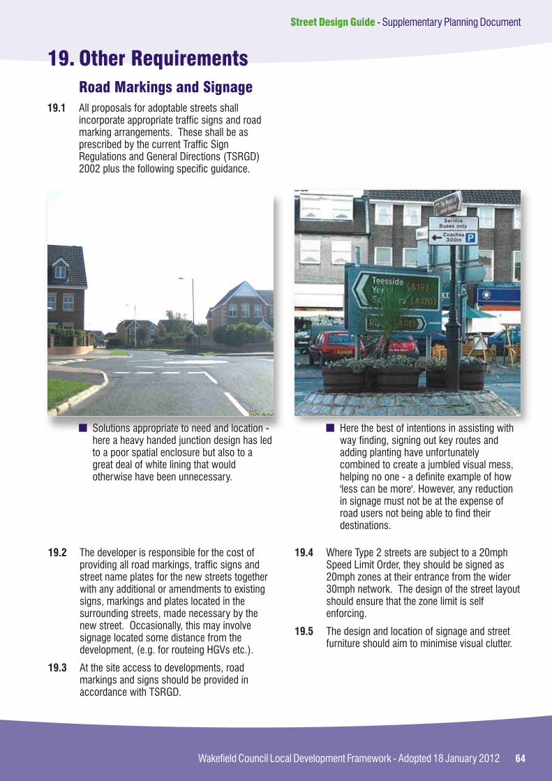
64Wakefield Council Local Development Framework - Adopted 18 January 2012
Street Design Guide - Supplementary Planning Document
19. Other Requirements
Road Markings and Signage
19.1 All proposals for adoptable streets shall incorporate appropriate traffic signs and road marking arrangements. These shall be as prescribed by the current Traffic Sign Regulations and General Directions (TSRGD) 2002 plus the following specific guidance.
Solutions appropriate to need and location - here a heavy handed junction design has led to a poor spatial enclosure but also to a great deal of white lining that would otherwise have been unnecessary.
Here the best of intentions in assisting with way finding, signing out key routes and adding planting have unfortunately combined to create a jumbled visual mess, helping no one - a definite example of how 'less can be more'. However, any reduction in signage must not be at the expense of road users not being able to find their destinations.
19.2 The developer is responsible for the cost of providing all road markings, traffic signs and street name plates for the new streets together with any additional or amendments to existing signs, markings and plates located in the surrounding streets, made necessary by the new street. Occasionally, this may involve signage located some distance from the development, (e.g. for routeing HGVs etc.).
19.3 At the site access to developments, road markings and signs should be provided in accordance with TSRGD.
19.4 Where Type 2 streets are subject to a 20mph Speed Limit Order, they should be signed as 20mph zones at their entrance from the wider 30mph network. The design of the street layout should ensure that the zone limit is self enforcing.
19.5 The design and location of signage and street furniture should aim to minimise visual clutter.

65
Street Design Guide - Supplementary Planning Document
Wakefield Council Local Development Framework - Adopted 18 January 2012
19.6 Developers wishing to erect signs directing construction traffic or potential purchasers to a site must contact the Council for permission to erect approved signs. Signs that have not been approved will be removed.
19.7 Where a development requires changes to an existing Traffic Regulation Order (TRO) or a new order is required, the Developer shall pay all associated costs, including all consultation and legal costs. TROs are subject to statutory procedures and consultations. This can be a very lengthy process and a successful outcome is not guaranteed. The Developer must therefore obtain advice on the likely success of a TRO, the timescale involved, and take this into consideration when establishing a programme for development.
19.8 Planning conditions are normally expressed as the Grampian type requiring certain works (e.g. parking restrictions or traffic management measures) to be implemented. This does give developers the opportunity to design street layouts that avoid the necessity of imposing a TRO.
19.9 Where TRO's are critical to the Development, they should be completed and sealed prior to any commencement of development.
Traffic Regulation Orders (TRO's)
Alterations to the Existing Highway Procedures(Section 278)
Adoption Procedures(Section 38)
19.10 Where a development requires any changes to the existing highway network, the works must be undertaken by either the Highway Authority or its appointed agents. An agreement under Section 278 of the Highways Act will then be required. The Developer shall pay all associated costs, including bonds and supervision costs.
19.11 The Council's policies, requirements and procedures are set out in Pre-Application Leaflet "Alterations to the Existing Highway".
19.12 Where the alterations only involved construction within the existing footway or verge to connect a new access road a simpler 'Commercial Crossings' inspection and approval procedure may apply.
19.13 Wakefield MDC's adoption policies, requirements and procedures are set out in Appendix B and in the Council's document "Adopting new roads and the Advance Payment Code - Guidance for Developers".
19.14 A commuted sum is required for any elements where abnormal maintenance costs are likely to occur.
19.15 Likely elements for commuted sums include:
Bridges;?
Soakaways;?
Planting;?
Grassed areas;?
"non standard" products;?
Structures within the highway.?

66Wakefield Council Local Development Framework - Adopted 18 January 2012
Street Design Guide - Supplementary Planning Document
Street Lighting
Crime and Disorder
19.16 Wakefield MDC's procedures for the adoption (accrual) of Street Lighting and Illuminative Apparatus are set out in Appendix E.
19.17 In certain rural or other situations it may be necessary to provide alternative Street Lighting details (e.g. sensitive column designs in Conservation Areas, lights on buildings rather than columns in unlit villages, etc). These situations should be discussed further with the WMDC and Amey (the Council's PFI street lighting partners).
19.18 Local Authorities are obliged under Crime and Disorder Act 1998 to consider the crime and disorder implications of all planning applications. Crime prevention through environmental design (CPTED) is a concept that focuses on designing out crime by developing an understanding of the factors that are likely to contribute to a higher incidence of crime within a community. The built environment can have both a positive and negative impact upon criminal activities, and is a crucial factor to how safe and secure people feel within their community. However, planning out crime can only work if it is part of a wider strategy incorporating other measures such as regeneration, community involvement and town centre management.
19.19 Early discussions on crime prevention measures with the Police Architectural Liaison Officer and highway representatives should be undertaken to ensure the effects of such measures do not compromise highway and accessibility requirements.
Conservation Areas
19.20 Traditional paving materials, where they still exist, contribute to the character of a conservation area. Therefore, in carrying out maintenance, or the provision of new streets, within these areas it is necessary that traditional materials are used. These materials are likely to be made of stone, although alternative new materials such as tegula blocks, conservation kerbs and tarmac dressed with a suitable local aggregate may also be acceptable.
19.21 Street furniture should also be of appropriate materials in keeping with the surrounding area. Advice from the Council should be sought prior to designing or implementing any works.

67
Street Design Guide - Supplementary Planning Document
Wakefield Council Local Development Framework - Adopted 18 January 2012
20. Materials and Construction
General Approach
20.1 One of the key objectives set out in section 3.1 is the use of simple, appropriate, sustainable, well-detailed, high quality materials that form a cohesive family of components. The selected materials should assist in the making of high quality places, and need to reflect the existing character of an area. Specific instances (e.g. Conservation Areas, in the vicinity of Listed Buildings, or other areas of the historic environment) will sometimes need specific materials not acceptable elsewhere.
20.2 In general terms the key thing is to 'keep it simple'. A good street scene acts as an attractive backdrop to the built form of a development. Often when things do stand out it is because colours jar or styles clash, creating a discordant streetscene.
In these two locations a simple range of colours and materials all complement one another and the surrounding buildings or landscape creating a coherent streetscene.
20.3 All materials should combine to form a cohesive palette, with tones and textures that reflect or complement those used in the built development and the local area. There should be no need for a wide range of materials as areas tend to have just one or two different functions within them, while the built form and planting should add the visual interest to a space.
20.4 The future maintenance of materials should be considered, with the number of different materials used being minimised. On larger sites, where several developers may be present, this will require a co-ordinated approach, especially at the interface between different elements of the site.

68Wakefield Council Local Development Framework - Adopted 18 January 2012
Street Design Guide - Supplementary Planning Document
20.7 Where a Council Specification advised for any works varies from that contained in SHW, the requirements of the Council will apply.
20.8 All Works shall comply with the requirements of the Council's Standard Detail Drawings. Copies of the Standard Details can be found on the Highway Development Control web page.
20.9 Where proposals contain details not covered by the Standard Detail Drawings, scheme specific drawings shall be developed and submitted to the Council's Section 38 Team.
20.5 There should be no loose material adjacent to the highway.
Use of materials to delineate different street functions - here different coloured block paving highlight the visitor parking spaces. It should be noted that only subtle differences in tone or texture are required to create a clear visual distinction.
Here the unnecessary use of overly contrasting materials can tend to spoil an otherwise simple and attractive street environment. The use of tactile paving is to be encouraged however these can sit within a palette of tones that respond to other materials in the built form and street.
20.6 Unless stated otherwise, all highway works shall be in accordance with:
i) Any Specification for Highway Works advised by the Council;
ii) The current edition of "The "Specification for Highway Works" (SHW), published by Her Majesty's Stationery Office Ltd as Volume 1 of the Highways Agency' Manual of Contract Documents for Highway Works;
iii) The current edition of "The "Notes for Guidance on the Specification for Highway Works" (SHW), published by Her Majesty's Stationery Office Ltd as Volume 2 of the Highways Agency' Manual of Contract Documents for Highway Works.
Specification
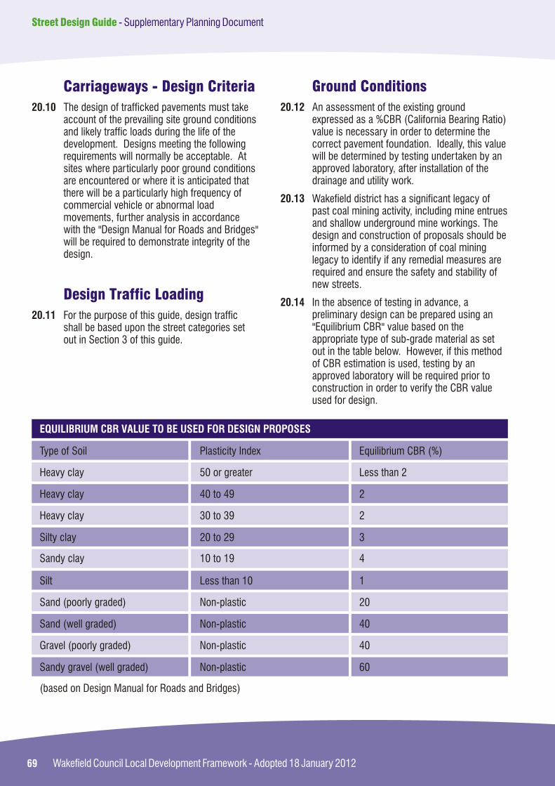
69
Street Design Guide - Supplementary Planning Document
Wakefield Council Local Development Framework - Adopted 18 January 2012
20.10 The design of trafficked pavements must take account of the prevailing site ground conditions and likely traffic loads during the life of the development. Designs meeting the following requirements will normally be acceptable. At sites where particularly poor ground conditions are encountered or where it is anticipated that there will be a particularly high frequency of commercial vehicle or abnormal load movements, further analysis in accordance with the "Design Manual for Roads and Bridges" will be required to demonstrate integrity of the design.
20.11 For the purpose of this guide, design traffic shall be based upon the street categories set out in Section 3 of this guide.
Carriageways - Design Criteria
Design Traffic Loading
20.12 An assessment of the existing ground expressed as a %CBR (California Bearing Ratio) value is necessary in order to determine the correct pavement foundation. Ideally, this value will be determined by testing undertaken by an approved laboratory, after installation of the drainage and utility work.
20.13 Wakefield district has a significant legacy of past coal mining activity, including mine entrues and shallow underground mine workings. The design and construction of proposals should be informed by a consideration of coal mining legacy to identify if any remedial measures are required and ensure the safety and stability of new streets.
20.14 In the absence of testing in advance, a preliminary design can be prepared using an "Equilibrium CBR" value based on the appropriate type of sub-grade material as set out in the table below. However, if this method of CBR estimation is used, testing by an approved laboratory will be required prior to construction in order to verify the CBR value used for design.
Ground Conditions
Heavy clay 50 or greater Less than 2
Type of Soil Plasticity Index Equilibrium CBR (%)
Heavy clay 40 to 49 2
Heavy clay 30 to 39 2
Silty clay 20 to 29 3
Sandy clay 10 to 19 4
Sand (poorly graded) Non-plastic 20
Silt Less than 10 1
Sand (well graded) Non-plastic 40
Gravel (poorly graded) Non-plastic 40
Sandy gravel (well graded) Non-plastic 60
(based on Design Manual for Roads and Bridges)
EQUILIBRIUM CBR VALUE TO BE USED FOR DESIGN PROPOSES

70Wakefield Council Local Development Framework - Adopted 18 January 2012
Street Design Guide - Supplementary Planning Document
Foundation
20.15 A granular foundation comprising sub-base or a combination of sub-base and a capping layer shall be provided in accordance with the table below:
Less than 2
CBR %
2
3
4
5-15
> than 15
PAVEMENT FOUNDATION DESIGN
600
Capping (mm)
450
350
300
250
-
150
Sub-base (mm)
150
150
150
150
-
-
Sub-base (mm)
-
300
275
225
150
OR+
+
+
+
+
+
+
20.16 It may be necessary to vary the foundation design to accommodate significant changes in sub-grade properties across the site. However, the foundation design should not vary frequently along the road. On sites where numerous changes in sub-grade properties are encountered, a design based upon the lowest CBR value will often provide the most satisfactory solution.
20.17 Where a CBR value between those in the above table is obtained (either through testing or with reference to the table in section 4.4.3.2) the lower value in the above table shall be used for the purpose of design.
20.18 Sub-grades that have CBR values significantly less than 2% and deform under construction traffic may be unsuitable to support the pavement. In this case, special measures will be required. Further advice is given in DMRB.
20.19 No material within 450mm of the finished road surface shall be frost susceptible.
20.20 Materials used in capping layers shall comply with the Specification for Highway Works Table 6/1 (and any additional requirements of the Council). The materials shall be sampled in the frequency stated in the Specification and tested to demonstrate that it has an in-situ CBR value of 15% (or equivalent test result). The Developer should provide confirmation that the tested materials comply with the required Specification.
20.21 Sub-base shall be Type 1 in accordance with the "Specification for Highways Works".

71
Street Design Guide - Supplementary Planning Document
Wakefield Council Local Development Framework - Adopted 18 January 2012
Pavement Design
20.22 A range of acceptable surfacing materials for use in pavement construction is set out below, although the list is not exhaustive. Other alternatives will be considered on an individual basis, especially in Conservation Areas or near to Listed Buildings. Where alternative surfacing materials are proposed, the developer must obtain written consent from the Council for the use of the material and must provide the Council with technical justification that the material meets the relevant design criteria.
Hot or cold applied coloured surfacing (resin system)
Hot Rolled Asphalt
Standard surface course materials using a coloured binder and coloured aggregate or chippings
Standard 80mm concrete-block paving surface course
'Tegula' or similar approved concrete-block paving surface course
Dense Bitumen Macadam (DBM)
Stone Mastic Asphalt, or similar alternative materials, by prior agreement with WMDC
ACCEPTABLE MATERIALS FOR SURFACE TO CARRIAGEWAYS AND SHARED SURFACES
20.23 Where alternative materials are proposed and accepted in writing by the Director, the Developer may be required to pay an enhanced commuted sum for the additional future maintenance costs incurred by the Council.
20.24 The Council's acceptance of any alternative material will be subject to the material meeting appropriate requirements of quality, durability, maintainability, and sustainability and, in the interests of safety, being compliant with the specification, particularly in respect of polished stone value (PSV) and aggregate abrasion (AAV).
20.25 Example designs for the bound pavement layers are detailed in the table below, which shows the minimum design thickness for a variety of alternative materials for the various street types within the scope of this guide. The pavement construction for any street types or roads not included in the table shall be subject to site-specific designs in accordance with DMRB Volume 7.

72Wakefield Council Local Development Framework - Adopted 18 January 2012
Street Design Guide - Supplementary Planning Document
STREET TYPE
PAVEMENT CONSTRUCTION
BASE COURSE (mm) BINDER COURSE (mm) SURFACE COURSE (mm)
1 DBM 85 DBM 55 HRA (45mm thick)
2 DBM 75 DBM 60 DBM 30 (6mm nominal size)
3 DBM 50 Sand 30 Concrete Block pavers (80mm thick)
4 DBM 50 Sand 30 Concrete Block pavers (80mm thick)
Industrial Road DBM 150 DBM 55 HRA (45mm thick)
20.26 Where alternative surfacing materials are proposed, appropriate construction depths will need to be provided, and agreed by the Council.
20.27 The value of commuted sums will be determined by the Council on a site specific basis. The sum will be calculated and details provided to the Developer in advance of entering into the appropriate agreement (e.g. Section 38 or 62) with the Council.
Standard surface course materials using a coloured binder and coloured aggregate or chippings
Hot or cold applied coloured surfacing (resin system)
Standard 80mm concrete-block paving surface course
'Tegula' or similar approved concrete-block paving surface course
Flags or small unit paving
Pre-cast concrete kerbing, channelling and edging products meeting the appropriate British and European Standards having a textured or exposed aggregate finish
Dense Bitumen Macadam (DBM)
MATERIALS FOR FOOTWAYS, KERBS, AND CROSSINGS ACCEPTABLE
Footways, Kerbs and Crossings
20.28 Footways and crossings shall be provided and laid out in accordance with the requirements of Section 3 of this Design Guide.
20.29 A range of acceptable materials that the Council might consider acceptable in the appropriate circumstances is included in the table below. Other alternatives will be considered on an individual basis, especially in Conservation Areas or near to listed buildings.

73
Street Design Guide - Supplementary Planning Document
Wakefield Council Local Development Framework - Adopted 18 January 2012
20.30 Example footway construction depths are shown below:
TYPE
FOOTWAY CONSTRUCTION
BASE/SUB BASE BINDER COURSE SURFACE COURSE
Pedestrian Footway or Footpath
150mm Type 1 50mm (20mm nominal size) DBM
20mm (6mm nominalsize) DBM
Vehicular Footway Crossing
150mm Type 1 (or300mm for more than one property)
60mm (20mm nominal size) DBM
20mm (6mm size) DBM
Industrial Footways 300mm 50mm 20mm
20.31 Where vehicular footway crossings are to be provided or in locations where vehicles are able to overrun the footway, the footway construction shall be strengthened to accommodate the additional load imposed by vehicular traffic.
20.32 Footway crossings shall not be used for service accesses to commercial properties, industrial accesses, or where particularly heavy vehicles are anticipated. In these circumstances, more formal access junctions shall be considered and the pavement construction shall meet the same requirements as the adjacent carriageway.
20.33 In certain circumstances the use of alternative materials to those set out in the above table may be permitted. Where alternative materials are proposed and accepted in writing by the Council, the Developer may be required to pay an enhanced commuted sum for the additional future maintenance costs incurred by the Council.
20.34 The Council's acceptance of any alternative material will be subject to the material meeting the appropriate requirements for quality, durability, maintainability, and sustainability.
20.35 Kerbs shall normally be provided alongside all running carriageways (Types 1 and 2) to provide an edge restrict to the carriageway construction, prevent vehicles overriding the footway, and facilitate the management of drainage flows.
20.36 Where kerbs are laid alongside the running carriageway they shall be laid with an up-stand of 100mm. At bus stops, this should be increased to 180mm, and Metro should be consulted for any additional requirements.
20.37 Drop Kerbs shall be used at pedestrian and vehicular crossing points. They should be constructed flush with the carriageway, and shall be constructed in accordance with the Standard Detail Drawings.
20.38 Pre-cast concrete channel blocks shall be installed in the road channel adjacent to the kerb wherever the longitudinal gradient along the road channel is between 1 in 150 and 1 in 120. The channels shall be laid in accordance with the Standard Detail Drawings.
20.39 Tactile paving is required on all classified roads and bus routes (and other roads if required, in consultation with WMDC) to assist blind or partially sighted people. It should be utilised in accordance with national guidance. Suitable alternatives may be considered in particular circumstances, but will be subject to Council approval.
20.40 The value of commuted sums will be determined by the Council on a site specific basis. The sum will be calculated and details provided to the Developer in advance of entering into the appropriate agreement (e.g. Section 38 or 62) with the Council.

INDEX
Street Design Guide - Supplementary Planning Document
74Wakefield Council Local Development Framework - Adopted 18 January 2012
Street Design Guide - Supplementary Planning Document

75
Street Design Guide - Supplementary Planning Document
Wakefield Council Local Development Framework - Adopted 18 January 2012
Adoption Appendix B, 14.3, 16.7, 19.9-10Alternative Materials Appendix B, 20Audits 2.6
Bus Routes and Stops 4.18, 18.0, 20.36
Carriageway Narrowing 5.4 Car Clubs 11.30Car Parking 4.27, 10.11, 11.0, Appendix A Centreline Radii 4.19, 4.24, 4.26, 4.60Commuted Sums 19.14, 20.23, 20.40Connectivity 4.8, 4.20, 8.4, 9.1Connector Streets (Type 1) 4.12, 4.16- 4.21, 4.72, 5.2Conservation Areas 19.13, 19.17,19.20-21, 20.1, 20.22, 20.29Crossing Points 4.31, 8.16-22, 20.37Culs-de-sac 4.8, 4.20, 4.24, 4.26, 12.5Cycling 1.9, 3.3, 9.0
Design and Access Statements 2.6Design Manual for Roads & Bridges 4.40, 4.57, 9.10, 20.18, 20.10 Design Speeds 4.12, 4.13, 4.19, 4.24, 4.26, 4.60, 5.0Direct Vehicular Access 4.18, 4.23Disabled People 1.8, 2.2, 4.25, 4.31, 8.11, 9.8, 10.0 11,7Drainage 16.0, Appendix FDrives 6.9, 11.6, 11.13-15Dropped Kerbs 8.16, 8.19, 10.11, 20.31
Emergency Vehicles 1.8, 5.7, 11.12, 13.0
Flexibility 1.2, 3.1Flood Levels 1.4, 4.6, 4.14, 6.2, 6.11, 16.0Footways 8.0, 9.0, 10.3, 11.7, 14.3, 20Forward Visibility 4.19, 4.24, 4.26, 4.38, 5.4, 6.8, 7.0, 12.10
Garages 6.9, 9.13, 11.13-19Gates 4.53, 4.68, 11.4, 11.13Gateways 4.31, 5.4Gradients 6.0, 8.8, 10.3, 10.5, 12.6Ground Conditions 20.10, 20.12Guardrails 8.18
Hard Margins 4.21, 8.6, 11.16, 15.7Headroom 6.7, 13.5Home Zones 4.5, 4.9, 4.29-38, 5.2, 11.17
Industrial Developments 4.4, 4.54-4.70, 9.15, 11.32
Junction Layouts and Visibility 7.0

76Wakefield Council Local Development Framework - Adopted 18 January 2012
Street Design Guide - Supplementary Planning Document
Kerbing 4.40, 8.16, 8.19-20, 10.11,12.10,13.4, 14.2, 18.9, 20.28-20.40Key Objectives 20.1
Landscape 14.0Local Residential Streets (Type 2) 4.12, 4.17, 4.22-24, 5.2
Maintenance Appendix B, Appendix D Manual for Streets 1.2, 1.3, 4.1, 4.11, 7.7, Materials 1.5, 1.7, 1.15, 4.19, 4.24, 4.26, 4.28, 4.49, 4.67, 5.4, 6.1, 8.17,11.20,
11.27, 14.2, 20.0
Mini Roundabouts 5.5Mixed Use Schemes 4.57, 4.70
Neighbourhoods 8.2, 9.2
Pavement Design 20.0Pedestrians 1.8, 2.2-2.6, 3.2, 4.0, 5.2, 7.2, 7.20, 7.26, 8.0, 9.1, 9.7, 10.5, 11.16, 12.2,
13.4, 14.10 15.3
Pedestrian Refuges 8.19Police ALO 3.2, 8.4, 9.3, 11.20, 11.34, 19.14 Private Drives and Streets 4.4, 4.48-4.53, 4.59, 11.6, 13.4Public Transport 2.1, 2.4, 4.6, 4.54, 5.7, 11.2, 11.12, 18.0Public Utilities 15.0
Radii at Junctions 4.54, 7.0, 8.20Ramps 5.4, 8.11,10.0Refuse Vehicles 4.51, 11.12, 12.0Road Markings 19.1 - 7Road Safety Audits 2.6, Appendix B
Safer Places 3.1Servicing 1.8 4.14, 4.44, 5.4, 11.5, 11.32, 12.0Shared Surface Streets 4.9, 4.12, 4.25, 4.31, 5.3-5, 6.5, 7.30, 8.1, 10.3, 11.5,11.16, 12.12, 15.2,
Appendix B
Signage 1.6, 8.10, 19.1, 19.3, 19.6Specification 11.8, 14.8, 20.0, AppendicesSpeed Restraint 4.20 -26, 5.0, 7.29Steps 8.10-15, 10.3Street Hierarchy 1.8, 4.6-15Street Furniture 5.6, 8.5, 10.3, 10.13, 12.3, 15.3, 19.5, 19.21Street Lighting 1.8, 7.28, 8.1, 19.16, Appendix EStreet Types 1.14, 4.0, 6.2, 11.16, 12.9, 14.2Structures 6.1, 14.11, 17.0, Appendix DSUDS 16.0, Appendix FSustainability 1.7, 2.4 -2.6, 18.3, 20.34

77
Street Design Guide - Supplementary Planning Document
Wakefield Council Local Development Framework - Adopted 18 January 2012
Tactile Paving 4.31, 8.17, 9.7, 10.8, 10.12, 15.6, 20.39Traffic Regulation Orders (TRO's) 11.35, 19.7-9Transport Assessments 1.11, 2.6, 18.3Transport Statements 1.11, 2.6, 18.3Travel Plans 1.11, 2.6, 11.36, 18.3 Turning Heads 12.0
Verges 4.0, 4.9, 4.49, 14.3, 14.9-10Visibility 4.22, 5.4, 6.8, 7.0, 8.3, 8.21, 9.10, 11.18, 12.10, 14.3, 14.5, 14.8, 15.3
Vertical Alignment 6.0Visitor Parking 11.0, Appendix A
Widths 4.39 - 47, 7.22, 8.5-7, 9.5-7

APPENDIX A
Supplementary Planning Guidance (SPG7)District Wide Parking Standards
78Wakefield Council Local Development Framework - Adopted 18 January 2012
Street Design Guide - Supplementary Planning Document
AppendicesAppendix A Supplementary Planning Guidance (SPG7)
District Wide Parking Standards
Appendix B Adoption Procedures
Appendix C Section 278 Procedures
Appendix D Structural Procedures
Appendix E Street Lighting Procedures
Appendix F Drainage Procedures
78
92
98
102
108
112

79
Street Design Guide - Supplementary Planning Document
Wakefield Council Local Development Framework - Adopted 18 January 2012
1 Introduction
1.1 Recent developments in planning policy have seen a move away from specifying maximum levels of parking in residential areas, towards defining minimum parking levels. This is in recognition of the on-street parking congestion, which puts the safety of drivers, cyclists and pedestrians at risk.
1.2 Whilst minimum parking levels are now required in residential areas, maximum parking levels will remain in industrial and commercial areas. This is in recognition of the fact that continued expansion of highway growth is neither desirable or feasible.

80Wakefield Council Local Development Framework - Adopted 18 January 2012
Street Design Guide - Supplementary Planning Document
1. Customer Parking
Town centre and neighbourhood shops (up to 150 sq.m approx) hairdressers, undertakers, travel agents, post office, dry cleaners,pet shops, hire shop
Supermarkets: < 5000 sq.m >5000 sq.m
Large comparison shops (non food retail stores)
DIY stores
Garden centres
Membership clubs & retail warehousing
2. Staff Parking
3. Service Vehicle parking
< 5000 sq m 5000 - 10000 sq m> 10000 sq m
4. Cycle Parking
5. Disabled motorists
1 space per:
30 sq m
14 sq m15 sq m
20 sq m
20 sq m
25 sq m
25 sq m
1 space per:
100 sq m
1 space per:
500 sq m 750 sq m 1000 sq m
1 space per:
500 sq m
5% of the total capacity
In town centres this standard will be replaced by the operational minimum requirement
Adequate space for delivery vehicle parking and loading bays
Secure cycle storage plus "Sheffield" type stands
In addition
USE CLASS A1: SHOPS

81
Street Design Guide - Supplementary Planning Document
Wakefield Council Local Development Framework - Adopted 18 January 2012
1. Customer Parking
All financial and professional service developments. To include:
Banks, Building Societies, estate agents, post offices, accountancy, employment agencies, betting shops
Town centre
2. Staff Parking
3. Cycle Parking
4. Disabled motorists
1 space per:
30 sq m
Presumption against car parking
1 space per:
30 sq m
1 space per:
3 staff
5% of the total capacity
In town centres this standard will be replaced by the operational minimum requirement
Secure cycle storage plus "Sheffield" type stands
In addition
USE CLASS A2: FINANCIAL AND PROFESSIONAL SERVICES
1. Customer Parking
But in areas with poor accessibility to public transport
In the town centre
2. Staff Parking
3. Cycle Parking
4. Disabled motorists
1 space per:
10 sq m
5 sq m
Presumption against any parking
1 space per:
3 staff
1 space per:
50 sq m of public floor area
5% of the total capacity
Includes drive through restaurants
In town centres this standard will be replaced by the operational minimum requirement
Secure cycle storage plus "Sheffield" type stands
In addition
USE CLASS A3: RESTAURANTS, SNACK BARS AND CAFES
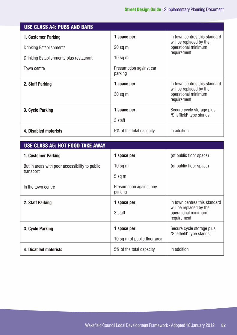
82Wakefield Council Local Development Framework - Adopted 18 January 2012
Street Design Guide - Supplementary Planning Document
1. Customer Parking
Drinking Establishments
Drinking Establishments plus restaurant
Town centre
2. Staff Parking
3. Cycle Parking
4. Disabled motorists
1 space per:
20 sq m
10 sq m
Presumption against car parking
1 space per:
30 sq m
1 space per:
3 staff
5% of the total capacity
In town centres this standard will be replaced by the operational minimum requirement
In town centres this standard will be replaced by the operational minimum requirement
Secure cycle storage plus "Sheffield" type stands
In addition
USE CLASS A4: PUBS AND BARS
1. Customer Parking
But in areas with poor accessibility to public transport
In the town centre
2. Staff Parking
3. Cycle Parking
4. Disabled motorists
1 space per:
10 sq m
5 sq m
Presumption against any parking
1 space per:
3 staff
1 space per:
10 sq m of public floor area
5% of the total capacity
(of public floor space)
(of public floor space)
In town centres this standard will be replaced by the operational minimum requirement
Secure cycle storage plus "Sheffield" type stands
In addition
USE CLASS A5: HOT FOOD TAKE AWAY

83
Street Design Guide - Supplementary Planning Document
Wakefield Council Local Development Framework - Adopted 18 January 2012
1. Car Parking
a. Officesi) In town centres and locations with good public transport accessibility ii) In locations with medium public transport accessibilityiii) In locations with poor public transport accessibility
b Light Industry(where buildings are designed for industrial purposes)
2. Cycle Parking
3. Disabled motorists
1 space per:
Minimum operational requirement
25 sq m
20 sq m
See Class B2
1 space per:
150 sq m
5% of the total capacity
Offices not within A2Research & development, studios, laboratories, high tech, light industry
Secure cycle storage plus "Sheffield" type stands
In addition
USE CLASS B1: BUSINESS
1. Car Parking
i) In town centres and locations with good public transport accessibility
ii) In locations with medium public transport accessibility
iii) In locations with poor public transport accessibility
2. Service Vehicle Parking
3. Cycle Parking
4. Disabled motorists
1 space per:
Minimum operational requirement
50 sq m
40 sq m
1 space per:
300 sq m
1 space per:
150 sq m
5% of the total capacity
Adequate space for delivery vehicle parking and loading bays
Secure cycle storage plus "Sheffield" type stands
In addition
USE CLASS B2: INDUSTRY

84Wakefield Council Local Development Framework - Adopted 18 January 2012
Street Design Guide - Supplementary Planning Document
1. Car Parking
Wholesale warehouses, distribution centres
2. Service Vehicle parking
3. Cycle Parking
4. Disabled motorists
1 space per:
150 sq m
1 space per:
300 sq m
1 space per:
500 sq m
5% of the total capacity
Plus provision in accordance with Class B1 for any office
Secure cycle storage plus "Sheffield" type stands
In addition
USE CLASS B8: STORAGE AND DISTRIBUTION
1. Car Parking
Hotels, motels, boarding houses, B& Bs
2. Staff Parking
4. Cycle Parking
5. Disabled motorists
1 space per:
bedroom
1 space per:
3 staff
1 space per:
10 bedrooms
5% of the total capacity
Other facilities will be subject to relevant standards eg for restaurant see class A3
Secure cycle storage plus "Sheffield" type stands
Operational minimum 2 spaces
In addition
USE CLASS C1: HOTELS, MOTELS AND GUEST HOUSES
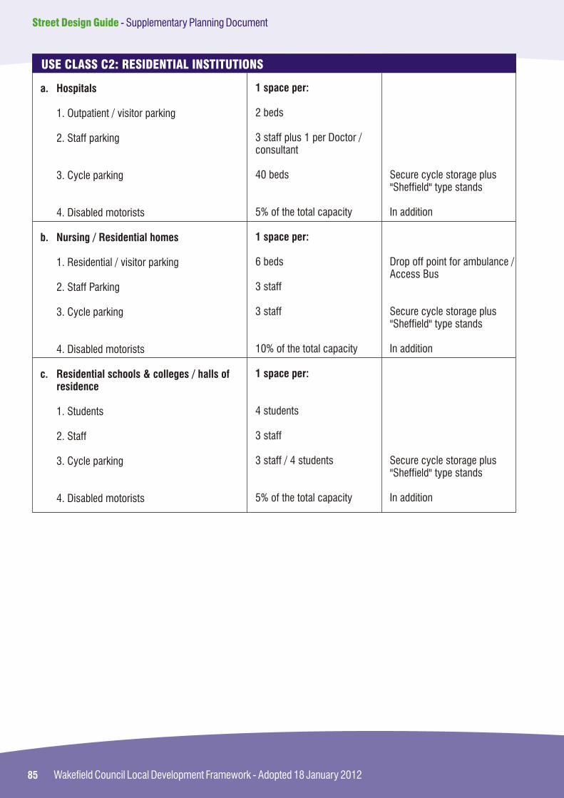
85
Street Design Guide - Supplementary Planning Document
Wakefield Council Local Development Framework - Adopted 18 January 2012
a. Hospitals
1. Outpatient / visitor parking
2. Staff parking
3. Cycle parking
4. Disabled motorists
b. Nursing / Residential homes
1. Residential / visitor parking
2. Staff Parking
3. Cycle parking
4. Disabled motorists
c. Residential schools & colleges / halls of residence
1. Students
2. Staff
3. Cycle parking
4. Disabled motorists
1 space per:
2 beds
3 staff plus 1 per Doctor / consultant
40 beds
5% of the total capacity
1 space per:
6 beds
3 staff
3 staff
10% of the total capacity
1 space per:
4 students
3 staff
3 staff / 4 students
5% of the total capacity
Secure cycle storage plus "Sheffield" type stands
In addition
Drop off point for ambulance / Access Bus
Secure cycle storage plus "Sheffield" type stands
In addition
Secure cycle storage plus "Sheffield" type stands
In addition
USE CLASS C2: RESIDENTIAL INSTITUTIONS

86Wakefield Council Local Development Framework - Adopted 18 January 2012
Street Design Guide - Supplementary Planning Document
1. Dwelling Houses
Dwellings with 1 bedroom
Dwellings with 2 or 3 bedrooms
Dwellings with 4 or more bedrooms
2. Flats
1 bedroom
2 + bedroom
Bedsits
3. Sheltered Housing
Residential / visitor parking
Staff
Disabled motorists
4. Houses in Multiple Occupancy
5. Hostels
Cycle Parking
1 space
2 spaces
3 spaces
1 space
2 spaces
1 space per 2 units
1 space per 6 units
1 space per 3 staff 10% of the total capacity
0.5 per unit
4 residents
1 space per:
Unit
Conversions in town centres should provide parking at an operational minimum
Developments served by an informal road layout should include 1 space for visitor parking per 4 units
Drop off point for ambulance / Access Bus
Space to be made for cycles within dwelling or garage or separate cycle store
USE CLASS C3: RESIDENTIAL

87
Street Design Guide - Supplementary Planning Document
Wakefield Council Local Development Framework - Adopted 18 January 2012
A. Public Halls, community Centres, places of worship, Libraries, museums, art Galleries
1. Visitor parking
2. Staff Parking
3. Cycle parking
4. Disabled motorists
5. Service vehicle parking
B. Clinics, Health Centres, Vets Consulting rooms
1. Visitor parking
2. Staff parking
3. Cycle parking
4. Disabled motorists
5. Service vehicle parking
C. Education
Visitor parking
Day Nurseries / playgroupsAfter school clubs
Primary Schools
Secondary Schools
Sixth form colleges / further education
Non residential and training centres
2. Staff Parking
1 space per:
5 seats or per 50 sq m
3 staff
50 sq m
5% of the total capacity
Space for deliveries
1 space per:
4 spaces per consulting room
Doctor or equivalent plus 1 space per 3 other staff
5 staff
5% of the total capacity
Space for deliveries
1 space per:
6 children
Classroom or 30 pupils
10 students
10 students
10 students
1 space per:
3 staff
In town centres this standard will be replaced by the operational minimum requirements
Secure cycle storage plus "Sheffield" type stands
In addition
In town centres this standard will be replaced by the operational minimum requirements
Secure cycle storage plus "Sheffield" type stands
In addition
USE CLASS D1: NON RESIDENTIAL INSTITUTIONS

88Wakefield Council Local Development Framework - Adopted 18 January 2012
Street Design Guide - Supplementary Planning Document
3. Cycle Parking
4. Disabled motorists
1 space per:
10 students
5% of the total capacity
Secure cycle storage plus "Sheffield" type stands
Operational minimum 2 spaces
In addition
USE CLASS D1: NON RESIDENTIAL INSTITUTIONS (continued)
A. Cinemas and concert venues
1. Visitor parking
2. Staff Parking
3. Cycle parking
4. Disabled motorists
5. Service vehicle parking
B. Community centres and Church halls, public halls, Dance halls, bingo halls, Working men's clubs
1. Visitor parking
2. Staff parking
3. Cycle parking
4. Disabled motorists
5. Service vehicle parking
C. Leisure centres, swimming Pools, bowling alleys, sports Halls, gymnasium
1. Visitor parking
2. Staff parking
3. Cycle parking
1 space per:
5 seats
3 staff
50 seats
5% of the total capacity
Space for deliveries
1 space per:
50 sq m
3 staff
50 sq m
5% of the total capacity
Space for deliveries
1 space per:
4 patrons
3 staff
50 sq m
In town centres this standard will be replaced by the operational minimum requirements
Secure cycle storage plus "Sheffield" type stands
In addition
In town centres this standard will be replaced by the operational minimum requirements
Secure cycle storage plus "Sheffield" type stands
In addition
In town centres this standard will be replaced by the operational minimum requirements
Secure cycle storage plus "Sheffield" type stands
USE CLASS D2: ASSEMBLY AND LEISURE

89
Street Design Guide - Supplementary Planning Document
Wakefield Council Local Development Framework - Adopted 18 January 2012
4. Disabled motorists
5. Service vehicle parking
6. Coach parking
D. Outdoor sports complexes football / rugby pitches, tennis courts
1. Visitor parking
2. Staff Parking
3. Cycle parking
4. Disabled motorists
5. Coach Parking
E. Stadia
1. Visitor parking
2. Staff parking
3. Cycle parking
4. Disabled motorists
5. Service vehicle parking
F. Riding Stables / Equestrian Centres
1. Visitors
2. Horse boxes
5% of the total capacity
Space for deliveries
Space for coaches
1 space per:
3 players
3 staff
10 players
5% of the total capacity
2 pitches
1 space per:
5 seats
3 staff
50 sq m
5% of the total capacity
Space for deliveries
1 space per:
2 horses on the yard
150 sq m of arena
In addition
In town centres this standard will be replaced by the operational minimum requirements
Secure cycle storage plus "Sheffield" type stands
In addition
Secure cycle storage plus "Sheffield" type stands
In addition
USE CLASS D2: ASSEMBLY AND LEISURE (continued)

90Wakefield Council Local Development Framework - Adopted 18 January 2012
Street Design Guide - Supplementary Planning Document
A. Car Sales showrooms
1. Customer parking
2. Staff Parking
3. Cycle parking
4. Disabled motorists
5. Transporter
B Garages, petrol filling Station, car repair workshop, MOT station
1. Customer parking
2. Staff Parking
3. Cycle parking
4. Disabled motorists
5. Transporter
C. Private Hire Office / Taxi Office
1. Taxis
2. Staff
3. Disabled motorists
D. Theatres and Nightclubs
1. Visitor parking
2. Staff Parking
3. Cycle parking
4. Disabled motorists
5. Service Vehicle / Deliveries
1 space per:
10 cars displayed
3 staff
150 sq m
5% of total capacity
Space for deliveries
1 space per:
3 spaces per repair bay50 sq m (sales area)
3 staff
150 sq m
5% of total capacity
Breakdown / towing vehicleSpace for tanker deliveries
1 space per:
Car operating from the unit
3 staff
5% of the total capacity
1 space per:
5 seats
3 staff
50 seats
5% of total capacity
Space for deliveries
To be clearly designated
To be clearly designated
Secure cycle storage plus "Sheffield" type stands
In addition
Secure cycle storage plus "Sheffield" type stands
In addition
In addition
In town centres this standard will be replaced by the operational minimum requirements
Secure cycle storage plus "Sheffield" type stands
In addition
MISCELLANEOUS (Sui Generis)

91
Street Design Guide - Supplementary Planning Document
Wakefield Council Local Development Framework - Adopted 18 January 2012
92Wakefield Council Local Development Framework - Adopted 18 January 2012
Street Design Guide - Supplementary Planning Document
APPENDIX B
Adoption Procedures
Appendices
Appendix B Adoption Procedures
Appendix A Supplementary Planning Guidance (SPG7)District Wide Parking Standards
Appendix C Section 278 Procedures
Appendix D Structural Procedures
Appendix E Street Lighting Procedures
Appendix F Drainage Procedures
78
98
102
108
112
92

93
Street Design Guide - Supplementary Planning Document
Wakefield Council Local Development Framework - Adopted 18 January 2012
Provide evidence of the right or consent to ?discharge surface water from the proposed highway to an existing public sewer, proposed public sewer (see below) or watercourse;
Provide a bond;?
Pay an administration and inspection fee;?
Pay a legal fee;?
Pay a commuted sum (if applicable).?
2.3 Any drains constructed for the sole purpose of discharging surface water run-off from the adopted highway areas will be adopted as highway and become maintainable at public expense by WMDC.
2.4 Any sewer located within the adopted highway but which, in addition to the discharge of run-off from the highway, accepts storm water discharges from areas outside the adopted highway (e.g. roof drainage or surface run-off from private plots) shall not be adopted under the highway adoption Agreement. Such sewers must be approved and adopted by the Water Authority (Yorkshire Water) by means of an Agreement under Section 104 of the Water Industry Act 1991. Consent to discharge highway run-off into sewers adopted under a Section 104 Agreement must be obtained from the Water Authority.
2.5 In certain circumstances it may be permissible for highway run-off to discharge to Soakaways, provided consent has been obtained from the Land Drainage Authority or the Environment Agency. Adoptable soakaways must be located in highway land immediately adjacent to the adopted street. Percolation tests will be required in order to demonstrate that the soakaway proposals can accommodate the appropriate level of run-off.
2.6 In exceptional circumstances, soakaways may be permitted within the adoptable highway provided that the strength of the adjoining carriageway is increased in agreement with WMDC.
1. Adoption policy
2. Requirements for adoption
1.1 It is the policy of WMDC to adopt (as Highway maintainable at public expense) streets and associated areas of new developments that serve;
Residential developments comprising more ?than 5 dwellings; and
Multiple building, multiple occupation, ?industrial and commercial developments (i.e. developments occupied by more that one company).
1.2 The layout of the street or other area to be offered for adoption must comply with the adoptable layouts and standards referred to in this guide and the requirements stated below.
1.3 In exceptional cases, areas not meeting the above criteria may be considered for adoption on a site by site basis.
1.4 Developers wishing to promote private streets should refer to section 3.2.3 of the main Street Design Guide.
2.1 Works in accordance with this guide will normally be adopted by Agreement under Section 38 of the Highways Act. This requires the Developer to enter into a Legal Agreement with the Highway Authority (i.e. WMDC). In certain circumstances adoption arrangements may be made under alternative agreements but these circumstances tend to be exceptional. Such alternative agreements are outside the scope of this guide.
2.2 In order to enter into a Section 38 Agreement the Developer shall:-
Obtain Full Planning Permission for the ?development, including approval of any reserved matters relating to the works to be offered for adoption;
Prove title to the land that will, within the ?Agreement, be dedicated as Public Highway;
Provide approved details of all easements ?that may be necessary for the development within the areas to be adopted as highway;

94Wakefield Council Local Development Framework - Adopted 18 January 2012
Street Design Guide - Supplementary Planning Document
3. Detail to be provided by the developer
3.1 The Developer shall, prior to entering into the adoption agreement, submit to WMDC for their approval, design details of the proposed works to be adopted. The details shall be in accordance with the requirements of this guide and shall include (but not be limited to) the following:-
Geometry and Layout
?A coloured plan or plans at a scale of not less that 1:500 indicating the limit of the proposed area of highway to be offered for adoption, showing a north point, plus existing street names and postal numbers;
?Plans at a scale of no less than 1:500 indicating the position and layout of all carriageways, footways, footpaths, cyclepaths, verges, service strips, visibility splays, traffic calming features, surface water drainage (including gully positions), parking bays or lay-bys, vehicular crossings, traffic signs, road markings, and highway retaining walls or structures;
?A plan or plans showing the position relative to the proposed highway of proposed dwellings and other buildings, private accesses, car parking areas and service yards;
?A plan or plans showing the layout of alternative specification materials that will be subject to special approval and may necessitate the payment of a commuted sum;
?Longitudinal sections along the line of the proposed carriageways (normally drawn to 1 to 10 vertical exaggeration). The sections shall show the existing ground levels, the proposed centreline and channel levels, horizontal alignment detail and vertical alignment details including gradients and vertical curves. Where appropriate the longitudinal sections shall also show the profile of foul and surface water drains, including the positions of manholes, pipe sizes and gradients.
Construction Details
Typical cross section drawings showing the ?relative position and construction of carriageways, footways and verges including details of kerbing and edging. Reference shall be made to the Specification and Standard Detail Drawings as appropriate;
Typical detail drawings showing the ?construction of any kerbing, channelling, edging, drainage components and chambers not covered by the details contained in the Standard Detail Drawings.
Ground Conditions
A geotechnical report, including details of ?CBR test results at the proposed formation level. The report should also confirm if the highest ground water table (taking into account time of year) is likely to be located within 600mm of the proposed formation level.
Drainage
Details of existing and proposed surface and ?foul water drainage, including the layout of proposed highway gullies or other mean of intercepting run-off;
Calculations of surface water run-off ?together with hydraulic calculations or simulation modelling to demonstrate the satisfactory operation of any carrier drains to be adopted by the highway authority;
Chamber schedules for all manholes and/or ?catchpits forming part of the highway drainage system;
Details of all easements and discharge ?consents.
Landscape
Details of all landscape proposals within the ?adoptable highway including planting layouts, specifications and maintenance proposals.

95
Street Design Guide - Supplementary Planning Document
Wakefield Council Local Development Framework - Adopted 18 January 2012
Other Features (Structures)
Specialist information relating to the ?requirements of any bridges, culverts, headwalls, retaining walls or other highway structures. The details shall be provided on separate drawings together with the appropriate applications "Approval in Principle" applications and associated calculations. See Appendix C for further details.
Safety Audit
Safety Audits are not required for all works ?designed in accordance with this guide. The Developer will be advised at the planning stage if an Audit is required although guidance is given in para 2.6 of the Design Guide. When required, the audit shall comprise a Stage 1 and/or a Stage 2 Road Safety Audit carried out in accordance with standard requirements. The safety audit report shall be submitted for approval together with a formal Exception Report prepared the designers. The Exception Report shall set out the proposals for dealing with any matters raised by the Audit Report.
Where a layout contains features not explicitly covered by this design guide, the details above shall be included within the Design and Access Statement (see paragraph 2.6 of the Design Guide on "Preparing Development Proposals") to assist WMDC in making a technical assessment of the proposals. The Design and Access Statement shall include the following:-
Detail of the design speed (or speeds) used ?in the design;
Justification of the visibility standards that ?have been applied to the design;
Special maintenance requirements;?
The layout of service corridors and the ?practicalities of maintenance;
On-street parking arrangements;?
Access arrangements;?
Addressing special needs (implications for ?people with disabilities).
4. Technical approval of design and specification
4.1 On receipt of the following initial drawings WMDC will assess the proposals:
1. one copy of a layout drawing showing coloured the areas to be included in the Agreement (see paragraph 5.4 of this Appendix for the relevant colours to use). The drawing must include a location plan.
2. one copy of a drawing showing longitudinal sections, cross sections, typical cross sections, and drainage details (including soakaways and SUDS where applicable).
3. Two copies of drawings showing safety fences, retaining wall details, and any other structures where appropriate including supporting calculations for approval.
4. A copy of a site investigation report and a mining report.
4.2 WMDC will issue to the Developer (or his agents) written technical approval of the design and specification of the proposed works to be adopted when:-
All design checks have been successfully ?completed;
Any further or amended details, as agreed ?during the checking process, have been provided and agreed by WMDC;
Any necessary safety audits have been ?approved and any actions necessitated by the matters raised by the safety audits agreed and, where appropriate, implemented.
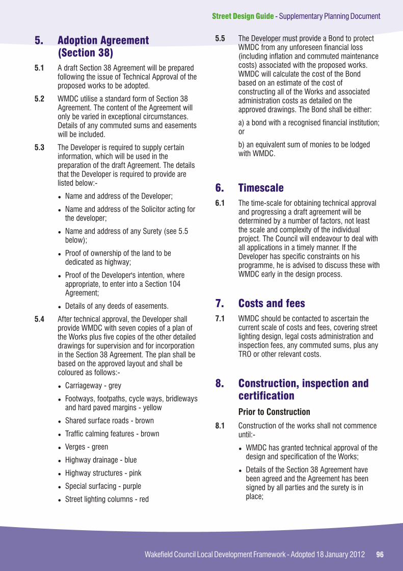
96Wakefield Council Local Development Framework - Adopted 18 January 2012
Street Design Guide - Supplementary Planning Document
5. Adoption Agreement(Section 38)
5.1 A draft Section 38 Agreement will be prepared following the issue of Technical Approval of the proposed works to be adopted.
5.2 WMDC utilise a standard form of Section 38 Agreement. The content of the Agreement will only be varied in exceptional circumstances. Details of any commuted sums and easements will be included.
5.3 The Developer is required to supply certain information, which will be used in the preparation of the draft Agreement. The details that the Developer is required to provide are listed below:-
Name and address of the Developer;?
Name and address of the Solicitor acting for ?the developer;
Name and address of any Surety (see 5.5 ?below);
Proof of ownership of the land to be ?dedicated as highway;
Proof of the Developer's intention, where ?appropriate, to enter into a Section 104 Agreement;
Details of any deeds of easements.?
5.4 After technical approval, the Developer shall provide WMDC with seven copies of a plan of the Works plus five copies of the other detailed drawings for supervision and for incorporation in the Section 38 Agreement. The plan shall be based on the approved layout and shall be coloured as follows:-
Carriageway - grey?
Footways, footpaths, cycle ways, bridleways ?and hard paved margins - yellow
Shared surface roads - brown?
Traffic calming features - brown?
Verges - green?
Highway drainage - blue?
Highway structures - pink?
Special surfacing - purple?
Street lighting columns - red?
5.5 The Developer must provide a Bond to protect WMDC from any unforeseen financial loss (including inflation and commuted maintenance costs) associated with the proposed works. WMDC will calculate the cost of the Bond based on an estimate of the cost of constructing all of the Works and associated administration costs as detailed on the approved drawings. The Bond shall be either:
a) a bond with a recognised financial institution; or
b) an equivalent sum of monies to be lodged with WMDC.
6.1 The time-scale for obtaining technical approval and progressing a draft agreement will be determined by a number of factors, not least the scale and complexity of the individual project. The Council will endeavour to deal with all applications in a timely manner. If the Developer has specific constraints on his programme, he is advised to discuss these with WMDC early in the design process.
7.1 WMDC should be contacted to ascertain the current scale of costs and fees, covering street lighting design, legal costs administration and inspection fees, any commuted sums, plus any TRO or other relevant costs.
Prior to Construction
8.1 Construction of the works shall not commence until:-
WMDC has granted technical approval of the ?design and specification of the Works;
Details of the Section 38 Agreement have ?been agreed and the Agreement has been signed by all parties and the surety is in place;
6. Timescale
7. Costs and fees
8. Construction, inspection and certification

97
Street Design Guide - Supplementary Planning Document
Wakefield Council Local Development Framework - Adopted 18 January 2012
All of the necessary fees associated with the ?Agreement, technical checks and Works inspections have been paid.
8.2 The Developer shall provide WMDC with written notice five weeks in advance of his intention to commence construction of the work. Should construction commence before an Agreement is in place, then such work is at the developer's own risk.
8.3 The Contractor and any Sub-Contractors shall have the relevant experience and capabilities to undertake the works. Where WMDC have no previous knowledge of a particular Contractor, the Contractor, prior to approval by WMDC, will be required to provide satisfactory references and also examples of similar work that they have successfully completed to the satisfaction of another Highway Authority.
Construction of the Works
8.4 The Developer shall remain responsible for the works on site and the day to day supervision.
8.5 Representatives of WMDC will inspect the works at regular intervals to ensure that they are being constructed in accordance with the approved drawings. For this purpose WMDC representatives must be given free access to the works in progress. The Developer must inform WMDC's Supervisor of the various stages of construction, giving reasonable notice, so that the Supervisor has the opportunity to inspect the Works.
8.6 It is the Developers responsibility to complete the works in a timely manner. Where appropriate a specific timescale for completing the works will be stated in the Section 38 Agreement.
Completion of the Works
8.7 A Provisional Certificate of Completion of the Works shall be issued when WMDC is satisfied:-
that the works are complete;?
that all highway structures work is complete, ?and a Construction Compliance Certificate has been submitted in accordance with BD02 Clause 4.2 (see Appendix C);
all lighting works are complete;?
and new planted landscape areas, grassed ?areas, trees or shrubs that are to be adopted are satisfactorily established;
the works have been jointly inspected (by ?WMDC and the Developer's Contractor) and no significant defects have been identified.
8.8 On the issue of the Provisional Certificate of Completion, WMDC shall reduce the amount of the Bond to 25% of the original amount, unless the Bond has been reduced to take account of any work already carried out.
8.9 Maintenance of the works shall remain the responsibility of the Developer for a period of 12 months commencing from the date of the Provisional Certificate of Completion (unless an alternative period is agreed).
8.10 A Final Certificate of Completion and Adoption shall be issued when:
The maintenance period expires, subject to the ?Works having been properly maintained during this period;
A further inspection of the Works shall be ?undertaken at the end of the maintenance period. If during this inspection, further defects in the Works are identified, WMDC will issue a list of remedial works. These works must be completed to the satisfaction of the WMDC prior to issue of the Final Certificate of Completion and Adoption;
Where appropriate, a copy of the Vesting ?Certificate issued by the Yorkshire Water for the adoption of any public sewers, has been submitted to the Council;
Any outstanding charges have been paid.?
8.11 The Final Certificate will be issued to the developer or his solicitor. It is the responsibility then for the developer to contact the Surety to have the Bond cancelled.
8.12 In the case of a cash Bond this will be returned by WMDC as soon as possible after the issue of the Final Certificate.
98Wakefield Council Local Development Framework - Adopted 18 January 2012
Street Design Guide - Supplementary Planning Document
APPENDIX C
Section 278 Procedures
Appendices
Appendix C Section 278 Procedures
Appendix A Supplementary Planning Guidance (SPG7)District Wide Parking Standards
Appendix B Adoption Procedures
Appendix D Structural Procedures
Appendix E Street Lighting Procedures
Appendix F Drainage Procedures
78
92
102
108
112
98

99
Street Design Guide - Supplementary Planning Document
Wakefield Council Local Development Framework - Adopted 18 January 2012
1. S278 Policy
2. Requirements
1.1 If your development requires any alteration to the existing highway network (eg for the creation or modification of access to your site) then these works must be undertaken by the Highways Authority or its appointed agents. An Agreement under S278 of the Highways Act 1980 will be required.
1.2 A S278 Agreement is an agreement between the Council and the developer which describes proposed modifications to the existing highway network to facilitate or service your development. It is not a contract to carry out work. A S278 Agreement only applies to works on existing highways. For details of adoption of new highways refer to Appendix B of this Design Guide.
2.1 The Agreement defines who will design the new works (either the Council or your consultant) and it will state that the Council, or its appointed contractor, will build the highway works on your behalf, at your expense, together with setting out a schedule of charges you will need to pay. Key elements which are likely to feature in a typical S278 Agreement may include:
The relevant Planning Permission for the ?development, including approval of any reserved matters relating to the works to be included in the S278 Agreement;
Prove title to the land;?
Convey land needed for any works for which ?the developer will fund and subsequently dedicate such land as public highway;
A schedule detailing the works to be done ?and showing on appropriate plans the extent of the improvement;
Provide a bond or surety;?
Pay the whole of the cost of the works and ?also to meet the Council's administrative, legal, design and supervision costs;
Pay a commuted sum (if applicable);?
Fund any Land Compensation Act Part I or II ?payments.
3. Detail to be provided by the developer
3.1 If you, or your consultant are preparing the detailed drawings these will need to be agreed with the Council prior to completion of the agreement. The agreed drawings are bound within the Agreement and shall include (but not be limited to) the following:-
A layout drawing which must be in ?accordance with the planning permission, or its conditions, and must include highway surface water drainage and street lighting proposals;
Longitudinal sections along the line of the ?proposed carriageways (normally drawn to 1 to 10 vertical exaggeration). The sections shall show the existing ground levels, the proposed centreline and channel levels, horizontal alignment detail and vertical alignment details including gradients and vertical curves. Where appropriate the longitudinal sections shall also show the profile of foul and surface water drains, including the positions of manholes, pipe sizes and gradient;
Typical cross section drawings showing the ?relative position and construction of carriageways, footways and verges including details of kerbing and edging. Reference shall be made to the Specification and Standard Detail Drawings as appropriate;
Typical detail drawings showing the ?construction of any kerbing, channelling, edging, drainage components and chambers not covered by the details contained in the Standard Detail Drawings;
A plan or plans showing the layout of ?alternative specification materials that will be subject to special approval and may necessitate the payment of a commuted sum;
A geotechnical report, including details of ?CBR test results at the proposed formation level. The report should also confirm if the highest ground water table (taking into account time of year) is likely to be located within 600mm of the proposed formation level;

100Wakefield Council Local Development Framework - Adopted 18 January 2012
Street Design Guide - Supplementary Planning Document
Details of all easements and discharge ?consents;
Specialist information relating to the ?requirements of any bridges, culverts, headwalls, retaining walls or other highway structures. The details shall be provided on separate drawings together with the appropriate applications "Approval in Principle" applications and associated calculations. See Appendix D for further details;
Detailed Safety Audits should be included at ?all relevant stages of the design and construction of the design.
4.1 It is normal for S278 Agreements to be taken out after planning permission has been granted. However WMDC strongly recommend that developers thinking about a S278 Agreement make an early approach to open preliminary discussions. It would be helpful to supply the following information:
An assessment of the proposed works ?including outline plans. The drawing must include a location plan;
Costs based on suitable professional advice;?
The proposed programme;?
The name of any proposed highway design ?consultant.
5.1 The time-scale for obtaining technical approval and progressing a draft agreement will be determined by a number of factors, not least the scale and complexity of the individual project. The Council will endeavour to deal with all applications in a timely manner. If the Developer has specific constraints on his programme, he is advised to discuss these with WMDC early in the design process.
4. Technical approval of design and specification
5. Timescale
6. Costs and fees
7. Construction, inspection and certification
6.1 WMDC should be contacted to ascertain the current scale of costs and fees, covering street lighting design, legal costs administration and inspection fees, any commuted sums, plus any TRO or other relevant costs.
Prior to Construction
7.1 Construction of the works shall not commence until:-
WMDC has granted technical approval of the ?design and specification of the Works;
Details of the Section 278 Agreement have ?been agreed and the Agreement has been signed by all parties and the surety is in place;
All of the necessary fees associated with the ?Agreement, technical checks and Works inspections have been paid.
7.2 The Developer shall provide WMDC with written notice five weeks in advance of his intention to commence construction of the work.
7.3 The Contractor and any Sub-Contractors shall have the relevant experience and capabilities to undertake the works. Where WMDC have no previous knowledge of a particular Contractor, the Contractor, prior to approval by WMDC, will be required to provide satisfactory references and also examples of similar work that they have successfully completed to the satisfaction of another Highway Authority.
Construction of the Works
7.4 The Developer shall remain responsible for the works on site and the day to day supervision.
7.5 Representatives of WMDC will inspect the works at regular intervals to ensure that they are being constructed in accordance with the approved drawings. For this purpose WMDC representatives must be given free access to the works in progress. The Developer must inform WMDC's Supervisor of the various stages of construction, giving reasonable notice, so that the Supervisor has the opportunity to inspect the Works.

101
Street Design Guide - Supplementary Planning Document
Wakefield Council Local Development Framework - Adopted 18 January 2012
7.6 It is the Developers responsibility to complete the works in a timely manner. Where appropriate a specific timescale for completing the works will be stated in the Section 278 Agreement.
Completion of the Works
7.7 A Provisional Certificate of Completion of the Works shall be issued when WMDC is satisfied:-
that the works are complete;?
that all highway structures work is complete, ?and a Construction Compliance Certificate has been submitted in accordance with BD02 Clause 4.2 (see Appendix D);
all lighting works are complete;?
and new planted landscape areas, grassed ?areas, trees or shrubs that are to be adopted are satisfactorily established;
the works have been jointly inspected (by ?WMDC and the Developer's Contractor) and no significant defects have been identified.
7.8 Maintenance of the works shall remain the responsibility of the Developer for a period of 12 months commencing from the date of the Provisional Certificate of Completion (unless an alternative period is agreed).
7.9 A Final Certificate of Completion and Adoption shall be issued when:
The maintenance period expires, subject to ?the Works having been properly maintained during this period;
A further inspection of the Works shall be ?undertaken at the end of the maintenance period. If during this inspection, further defects in the Works are identified, WMDC will issue a list of remedial works. These works must be completed to the satisfaction of the WMDC prior to issue of the Final Certificate of Completion and Adoption;
Where appropriate, a copy of the Vesting ?Certificate issued by the Yorkshire Water for the adoption of any public sewers, has been submitted to the Council;
Any outstanding charges have been paid.?
7.10 The Final Certificate will be issued to the developer or his solicitor. It is the responsibility then for the developer to contact the Surety to have the Bond cancelled.
7.11 In the case of a cash Bond this will be returned by WMDC as soon as possible after the issue of the Final Certificate.

102Wakefield Council Local Development Framework - Adopted 18 January 2012
Street Design Guide - Supplementary Planning Document
APPENDIX D
Structural Procedures
Appendices
Appendix D Structural Procedures
Appendix A Supplementary Planning Guidance (SPG7)District Wide Parking Standards
Appendix B Adoption Procedures
Appendix C Section 278 Procedures
Appendix E Street Lighting Procedures
Appendix F Drainage Procedures
78
92
98
108
112
102

103
Street Design Guide - Supplementary Planning Document
Wakefield Council Local Development Framework - Adopted 18 January 2012
1. Introduction
2. Definition of a highway structure
1.1 Because of the important design, safety, inspection and maintenance considerations involved, it is a requirement that Technical Approval procedures be followed for the design and construction of all new highway structures.
1.2 The Guidance Note is for the use of Developers and their Consultants intending to design and construct highway structures. It can also be used by any other persons seeking to construct private works for which the approval of the highway authority is required by statute.
1.3 The procedures defined in this document apply to:-
(a) Highway structures which are proposed for adoption by the Highway Authority under Section 38 of the Highways Act;
(b) Highway structures requiring consent of the Highway Authority under Section 167 of the Highways Act.
2.1 Highway structures are defined as follows:
(a) Any structure which carries vehicular or pedestrian traffic where the clear span dimension at any point exceeds 0.9 metres. This includes bridges, culverts, footbridges, cycleway bridges, etc.
(b) Any structure built within 3.66 metres of the highway which supports the highway or ground above the highway. This includes retaining walls, burr walls, headwalls, basements, cellars etc.
3. Adoption policy
4. Design approval procedure
3.1 In general, subject to compliance with the procedure defined in this document, the Highway Authority will adopt highway structures defined in 1.3(a) and 1.3(b) which either carry an adopted highway or support an adopted highway.
3.2 The Highway Authority will only adopt walls constructed to retain the highway if an embankment is not practicable.
3.3 Walls supporting private land adjacent to the highway will not be adopted and such walls must be constructed entirely outside the highway boundary.
3.4 When a highway structure is to be adopted, a commuted sum for future maintenance and renewal of the structure will be required by the Highway Authority.
3.5 Structures will not be adopted if the correct procedures have not been followed.
4.1 Technical approval of all highway structures will be required in accordance with Department of Transport Standard BD2 and the following:
The Technical Approval Authority shall be ?Wakefield Council Regeneration and Economic Growth;
All structures except walls below 1.5 metres ?retained height shall be classified as at least Category I (see BD2). The classification of walls less than 1.5 metres retained height shall be subject to agreement but will normally be Category 0. Approval in Principle (AIP) may still be required by the authority for category 0 structures.
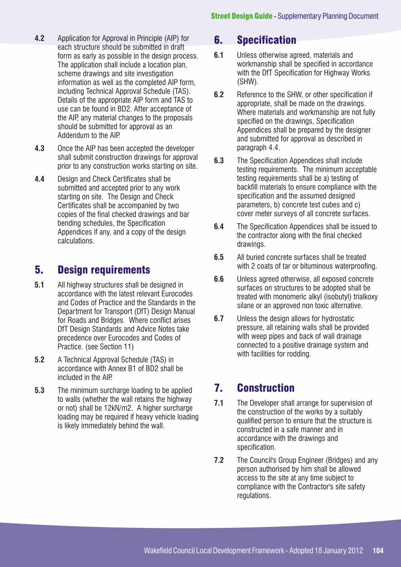
104Wakefield Council Local Development Framework - Adopted 18 January 2012
Street Design Guide - Supplementary Planning Document
4.2 Application for Approval in Principle (AIP) for each structure should be submitted in draft form as early as possible in the design process. The application shall include a location plan, scheme drawings and site investigation information as well as the completed AIP form, including Technical Approval Schedule (TAS). Details of the appropriate AIP form and TAS to use can be found in BD2. After acceptance of the AIP, any material changes to the proposals should be submitted for approval as an Addendum to the AIP.
4.3 Once the AIP has been accepted the developer shall submit construction drawings for approval prior to any construction works starting on site.
4.4 Design and Check Certificates shall be submitted and accepted prior to any work starting on site. The Design and Check Certificates shall be accompanied by two copies of the final checked drawings and bar bending schedules, the Specification Appendices if any, and a copy of the design calculations.
5.1 All highway structures shall be designed in accordance with the latest relevant Eurocodes and Codes of Practice and the Standards in the Department for Transport (DfT) Design Manual for Roads and Bridges. Where conflict arises DfT Design Standards and Advice Notes take precedence over Eurocodes and Codes of Practice. (see Section 11)
5.2 A Technical Approval Schedule (TAS) in accordance with Annex B1 of BD2 shall be included in the AIP.
5.3 The minimum surcharge loading to be applied to walls (whether the wall retains the highway or not) shall be 12kN/m2. A higher surcharge loading may be required if heavy vehicle loading is likely immediately behind the wall.
5. Design requirements
6. Specification
7. Construction
6.1 Unless otherwise agreed, materials and workmanship shall be specified in accordance with the DfT Specification for Highway Works (SHW).
6.2 Reference to the SHW, or other specification if appropriate, shall be made on the drawings. Where materials and workmanship are not fully specified on the drawings, Specification Appendices shall be prepared by the designer and submitted for approval as described in paragraph 4.4.
6.3 The Specification Appendices shall include testing requirements. The minimum acceptable testing requirements shall be a) testing of backfill materials to ensure compliance with the specification and the assumed designed parameters, b) concrete test cubes and c) cover meter surveys of all concrete surfaces.
6.4 The Specification Appendices shall be issued to the contractor along with the final checked drawings.
6.5 All buried concrete surfaces shall be treated with 2 coats of tar or bituminous waterproofing.
6.6 Unless agreed otherwise, all exposed concrete surfaces on structures to be adopted shall be treated with monomeric alkyl (isobutyl) trialkoxy silane or an approved non toxic alternative.
6.7 Unless the design allows for hydrostatic pressure, all retaining walls shall be provided with weep pipes and back of wall drainage connected to a positive drainage system and with facilities for rodding.
7.1 The Developer shall arrange for supervision of the construction of the works by a suitably qualified person to ensure that the structure is constructed in a safe manner and in accordance with the drawings and specification.
7.2 The Council's Group Engineer (Bridges) and any person authorised by him shall be allowed access to the site at any time subject to compliance with the Contractor's site safety regulations.

105
Street Design Guide - Supplementary Planning Document
Wakefield Council Local Development Framework - Adopted 18 January 2012
7.3 The Developer shall afford the Council's Group Engineer (Bridges) or his representative the opportunity to examine foundations and any work which is to be covered. A minimum notice period of 24 hours shall be provided and the examination will be carried out without unreasonable delay unless it is considered unnecessary when the Developer will be advised accordingly. Notice of concrete pours in reinforced concrete structures shall be not less than 48 hours.
7.4 Delivery tickets for all materials incorporated within the structure shall be retained for inspection and copies provided to the Council's Group Engineer (Bridges) if requested.
7.5 The Developer shall arrange for testing to be carried out in accordance with the specification.
7.6 Upon completion of the structure, the Developer shall request a final structural inspection which will be carried out by the Council's Group Engineer (Bridges) or his representative. Access equipment shall be provided by the Developer, where necessary, to allow all areas of the structure to be inspected. The Developer will be provided with a list of outstanding works or remedial works identified during the inspection.
7.7 A Provisional Certificate in accordance with the Section 38 Agreement will not be issued for the structure and the associated highway until the outstanding and remedial works to the structure are completed.
8.1 On completion of a structure which is to be adopted, the Developer shall provide the Highway Authority with a Maintenance Manual in accordance with BD62, "As Built, Operational and Maintenance Records for Highway Structures".
The Maintenance Manual shall include as a minimum:-
Location plan showing the structure and road ?name;
As built drawings and bar bending schedules;?
Names and addresses of contractors, sub-?contractors, materials and component suppliers etc;
8. As-built records
Test certificates;?
Cover meter survey results;?
Health and Safety File;?
9.1 Approximately 11 months after issue of the Provisional Certificate, the Council's Group Engineer (Bridges) or his representative will carry out a hand over inspection of the structure. Access equipment shall be provided by the Developer, where necessary, to allow all areas of the structure to be inspected. The Developer will be provided with a list of remedial works identified during the inspection.
9.2 A Completion Certificate in accordance with the Section 38 Agreement will not be issued for the structure and associated highway until the remedial works to the structure have been satisfactorily completed and the Maintenance Manual has been received by the Highway Authority.
10.1 At the time of writing, (September 2011) the applicability of design codes is changing. BD2 is version BD2/05, which refers to BS5400, which has been withdrawn by British Standards Institute. Other British Standards previously referred to are also now withdrawn and replaced with Eurocodes.
10.2 BD2/11 is expected soon, however the DfT has released Interim Advice Note IAN 124/11 which gives clear advice on use of Eurocodes.
10.3 In the interim period before BD2/11 is released, developers are required to include reference to the relevant Eurocodes and IAN 124/11 in the TAS attached to the AIP.
10.4 The latest information on Standards for Highway design can be found at the following web address:
http://www.dft.gov.uk/ha/standards/index.htm
9. Completion Certificate
10. Design documents

106Wakefield Council Local Development Framework - Adopted 18 January 2012
Street Design Guide - Supplementary Planning Document
11. Further information
11.1 If any further information or guidance is required it can be obtained from the Council at the address given below. If in any doubt, Developers are advised to contact the Council at an early stage to confirm that a proposal is acceptable.
Wakefield Metropolitan District CouncilRegeneration and Economic GrowthTransportation and HighwaysNewton BarPO Box 92WakefieldWF1 2TX
Contact:
Mr A J Dore Section Engineer (Bridges)
Telephone number: 01924 306035
Email: [email protected]

107
Street Design Guide - Supplementary Planning Document
Wakefield Council Local Development Framework - Adopted 18 January 2012
108Wakefield Council Local Development Framework - Adopted 18 January 2012
Street Design Guide - Supplementary Planning Document
APPENDIX E
Street Lighting Procedures
Appendices
Appendix E Street Lighting Procedures
Appendix A Supplementary Planning Guidance (SPG7)District Wide Parking Standards
Appendix B Adoption Procedures
Appendix C Section 278 Procedures
Appendix D Structural Procedures
Appendix F Drainage Procedures
78
92
98
102
112
108
109
Street Design Guide - Supplementary Planning Document
Wakefield Council Local Development Framework - Adopted 18 January 2012
1. Background
2. Street lighting design
3. Design by AMEY LG Ltd
1.1 Street Lighting services for Wakefield are provided through a private finance initiative (PFI) by Amey LG Ltd on behalf of WMDC. It is a condition of this continuing agreement that street lighting equipment which is intended to be maintained through the PFI must have been designed and installed to the appropriate standards.
1.2 Wakefield Council is pro-active in managing its energy consumption for the provision of street lighting. To this end, the total energy consumption for street lighting is capped at 2010/11 levels with new installations carbon off setting in line with the Climate Change Act targets of 80% reduction by 2050.
1.3 Laid out below are the options and mechanisms to meet items 1.1 and 1.2 above. With regard to 1.1, developers are requested to indicate their preference. Selecting one option for design and one option for installation.
2.1 In all cases the design will be within the current EU/ BS street lighting standards. Developers may either produce their own street lighting design or utilise Amey LG Ltd design service. If the Developer elects to undertake their own lighting design, these designs will be subject to a design check by Amey LG Ltd. A fee will be charged for this design check. If the Developer elects to use non-standard or decorative style streetlights, a commuted sum will be payable to meet costs over and above what is deemed to be a standard installation.
3.1 If a Developer requires Amey LG Ltd to undertake the design works, then the developer shall notify Amey LG Ltd in writing providing details of the proposed development. Upon receipt of the development details a design will be produced by Amey LG Ltd within 25 working days or period as may be agreed.
3.2 Amey LG Ltd will notify Wakefield Council of all ongoing design work at the monthly PFI progress meetings.
3.3 The costs of the design service payable by the Developer will be in accordance with the appropriate costs as provided by Amey LG Ltd.
3.4 If Amey LG Ltd prepares the design on behalf of the Developer the design is assumed to be fully compliant with appropriate specifications. Therefore a design check fee is not applicable.
3.5 In the event that a Developer makes subsequent changes to the layout of the development following the initial submission, Amey LG Ltd will undertake to make one amendment to the design. Any further changes to the layout will incur additional costs.
3.6 It is the Developers responsibility to make prospective property owners aware of the intention to install street lighting on the development, particularly those in close proximity to the column location. Requests for column re-sites after installation either from Developers or property owners will be deemed to be requests for additional design/installation work by the Developer, and will incur additional costs for the Developer.
4.1 If a Developer undertakes the design of its proposed street lighting Amey LG Ltd will undertake a design check in order to confirm whether or not the design complies with the appropriate street lighting standards. Such review shall be completed by Amey LG Ltd within 15 working days or other period as may be agreed.
4.2 The cost of the design check payable by the Developer will be in accordance with the appropriate costs supplied by Amey LG Ltd.
4.3 When in the reasonable opinion of Amey LG Ltd the design fails to meet the appropriate street lighting the Developer must undertake further work so as to make the design compliant. One further Design Check will be undertaken to allow rectification of errors, after which an additional fee for design check time will be charged. Failure to achieve the required standard of design will result in Wakefield MDC not accruing the apparatus.
4. Design by others

110Wakefield Council Local Development Framework - Adopted 18 January 2012
Street Design Guide - Supplementary Planning Document
5. Street lighting installation
5.1 Developers may choose to undertake to install the apparatus or alternatively elect to use the Amey LG Ltd installation service. In the event that the installation works are not carried out by Amey LG Ltd, then all works must be subjected to an installation check for which a fee will be charged. Connection to the mains electricity service must be direct to CE Electric (YEDL) underground mains cable. No part of the service cable is to be installed as a private maintained electric service supply. Connections to the underground electric main will require authorisation by the Unmetered Service Operator at CE Electric, for which a separate MPAN Number is required to recover the streetlight energy cost until the street light is adopted and formally handed over.
Installation by Amey LG Ltd
5.2 If a Developer requires street lighting equipment to be supplied, installed and connected by Amey LG Ltd then the Developer shall notify Amey LG Ltd in writing providing details of the proposed development. Amey LG shall undertake the supply, installation and connection of the equipment within 8 weeks from the date of notification or other period as may be agreed. Non standard equipment will generally require longer lead in periods.
5.3 Amey LG will notify Wakefield Council of all ongoing installation work at the monthly PFI progress meeting.
5.4 The costs of the supply, installation and connection of the equipment payable by the Developer will be as detailed in the Amey LG Ltd quotation provided prior to the commencement of the works. Having installed the apparatus on behalf of the Developer, the works are assumed to be fully compliant and will immediately be accrued into the scope of the PFI. No installation check fee is payable.
Installation by others
5.5 If a Developer undertakes the supply, installation and connection of equipment in respect of its proposed development, Amey LG Ltd will be entitled to undertake an installation check in order to confirm whether or not the installation complies with the appropriate street lighting standards. Such review shall be completed by Amey LG Ltd within 25 working days or other period as may be agreed.
5.6 The cost of the design check payable by the Developer will be in accordance with the appropriate costs supplied by Amey LG Ltd.
5.7 When in the reasonable opinion of Amey LG Ltd the supply, installation or connection fails to meet the appropriate standards the Developer must undertake all necessary further work so as to make the installation compliant.
5.8 Further installation checks will be undertaken, up to a maximum of 2, until such time as Amey LG Ltd believes the supply, installation or connection to meet the appropriate standard. In the event that following the 2nd installation check remedial works remain outstanding, Wakefield MDC may elect to instruct Amey LG Ltd to undertake all necessary remedial works after which time the apparatus will be immediately accrued into the scope of the PFI and the Developer will be recharged in full the actual cost of the remedial works undertaken or the Council may confirm that the proposed Apparatus will not be accrued.
6.1 Developers in discussion with the Council and Amey LG Ltd will strive to install an appropriately energy efficiency lighting scheme.
6.2 To meet the requirements of para 1.2, developers are required to make a contribution to offset the actual energy used over the lighting schemes' lifespan.
6.3 In addition to para 5.2, additional consideration is given to the fact that the Climate Change Act requires ongoing energy reduction over that period of time.
6. Energy efficiency

111
Street Design Guide - Supplementary Planning Document
Wakefield Council Local Development Framework - Adopted 18 January 2012
6.4 The developers' payments will be used to implement energy reduction initiatives such as lamp conversions, trimming, dimming and / or remote management of existing street lighting stock to make an energy reduction equal to the forecast energy from paras 6.1 and 6.2.
7.1 With effect from the date of confirmation received by WMDC from Amey LG Ltd that the Apparatus meets the required standards, the apparatus becomes accrued in to the scope of the PFI project and all commuted sums will become payable.
7.2 From the date of adoption, Wakefield Council becomes responsible for the payment of both energy and maintenance.
7. Adoption (accrual) of street lighting equipment

112Wakefield Council Local Development Framework - Adopted 18 January 2012
Street Design Guide - Supplementary Planning Document
APPENDIX F
Drainage Procedures
Appendices
Appendix F Drainage Procedures
Appendix A Supplementary Planning Guidance (SPG7)District Wide Parking Standards
Appendix B Adoption Procedures
Appendix C Section 278 Procedures
Appendix D Structural Procedures
Appendix E Street Lighting Procedures
78
92
98
102
108
112
113
Street Design Guide - Supplementary Planning Document
Wakefield Council Local Development Framework - Adopted 18 January 2012
1. General
1.1 Normally the highway drainage on new developments shall be connected to new drainage system that will be adopted by the water authority (Yorkshire Water) and shall be subject to a Section 104 agreement under the Water Industry Act 1991. Confirmation of this agreement must be provided to WMDC before entering into a Section 38 agreement for adoption of the highway. The roads shall not be adopted until Yorkshire Water has issued a Vesting Certificate for the drainage system or, where discharge to the drain is limited to highway run-off only, if it is to be adopted as a highway drain.
1.2 There may be occasions when the highway drainage will be connected to an existing public sewerage system. In that case the Developer will be required to provide evidence of consent from the appropriate authority to discharge drainage flow to the sewer. Similarly, written evidence must be provided of the right to discharge water from a highway drain into any receiving ditch or watercourse with no liability on the Council. Consent to discharge into a ditch or watercourse would normally be granted by the Environment Agency or the Lead Local Flood Authority.
1.3 All highway drains (including soakways) are to be located within land that is to be adopted as Highway. Only in exceptional circumstances will it be permissible for them to be located in private land and then it will require an easement agreement. This should be in place before, or be a condition of, the Section 38 Agreement.
1.4 Where a piped system discharges into an existing ditch or watercourse, the pipe invert (bottom of the inside of the pipe) must not be lower than the level of the average flow in the ditch or watercourse and it should always be at least 225mm above the ditch or watercourse invert. The end of the pipe shall be orientated so that it discharges at an angle less than 60 degrees to the direction of flow in the ditch or watercourse. The end of the pipe must have a headwall and apron which supports the bank above and adjacent to the pipe and prevents any scouring underneath the pipe. In addition, appropriate measures shall be incorporated to protect the banks of the ditch or watercourse
from scouring. It will also be necessary to comply with the requirements of the Environment Agency, Lead Local Flood Authority or local Internal Drainage Board. A flap must be provided at the outfall to prevent the intrusion of vermin or flood water.
1.5 Oil interceptors shall be installed as required by Environmental Health or the Environment Agency, and prior to a highway drain discharging into a soakaway.
1.6 If the proposed drain is to outfall to an existing highway drain, the Developer shall provide details to prove the capacity and condition of the existing drain prior to any approval being granted for the connection. A CCTV survey of the existing drain may be required and any improvement works found necessary shall be undertaken at the Developer's expense.
1.7 Drainage of other non-adopted areas into an existing or adoptable highway drain shall not be accepted.
1.8 Where private non-adoptable drives and other surfaces fall towards the adoptable highway, measures must be put in place to prevent surface water run-off from reaching the highway boundary and entering the highway drainage system.
2.1 Where there is or is likely to be run-off from landscaped areas, open spaces and adjoining land, appropriate arrangements shall be made for land drainage. This can include providing intercepting drains and ditches with satisfactory outfalls.
3.1 Appropriate measures shall be put in place to deal with any existing drainage systems within the development site, including any land drains, ditches, watercourses, outfalls from adjacent land or drainage systems, to the satisfaction of the Council, the Environment Agency and the owner of the systems. Consent of the Environment Agency or Lead Local Flood
2. Land drainage
3. Existing drainage systems

114Wakefield Council Local Development Framework - Adopted 18 January 2012
Street Design Guide - Supplementary Planning Document
Authority for piping an existing ditch or watercourse, in accordance with Section 23 of the Land Drainage Act 1991 must also be obtained on engineering and ecological grounds.
4.1 Sustainable Urban Drainage Techniques (SUDS) should be considered for all new development.
4.2 Where SUDS are proposed for highway drainage, discussions with all relevant parties must be entered into at an early stage (in advance of any planning application) to agree ownership and responsibility for the facility. The design of the SUDS facility must include adequate provision for future maintenance of the system.
4.3 Where a system of SUDS incorporates the use of soakaways for disposal of highway run-off, the soakaways shall be designed in accordance with the requirements of BRE Digest 365, amended for the minimum 30 year critical storm event. The design, together with details of the associated soakaway tests shall be submitted to the Council for their approval. The S.38 Inspector is to be informed of tests prior to commencing.
4.4 The Developer will be required to pay commuted sums for the future maintenance of SUDS and other non-standard drain elements, including above and below ground flow attenuation systems and pollution control devices that are adopted as highway. Details of the sums payable will be calculated on a site-specific basis.
5.1 The hydraulic design of adoptable piped highway drains must meet the requirements of the current edition of 'Sewers for Adoption' published by WRc plc.
4. Sustainable urban drainage systems (SUDS)
5. The hydraulic design of adoptable highway drains
5.2 Hydraulic calculations using the specified method of calculation and format shall be submitted for approval of the Council together with design drawings showing the layout of the proposed drains. The layout drawing shall be annotated to enable easy cross reference with the calculations. Output from an approved computer programme using the specified method and parameters shall be acceptable.
6.1 The system must be designed to meet the requirements of the current edition of 'Sewers for Adoption' published by WRc plc.
6.2 The system should be designed not to flood any part of the highway or site in a 1 in 100 year return period design storm or any other return period that is set out in any latest version of 'Sewers for Adoption'.
6.3 The design should also show the line and extent of flow paths and the potential effects of flooding if storms are greater than those allowed for by the design.
7.1 The minimum pipe diameter for adoptable highway drains and gully connections is 150mm.
8.1 The use of combined kerb/drainage systems will not normally be accepted for new development.
8.2 Consideration may be given to the use of a system of combined kerb/drainage in order to overcome a site-specific difficulty. Where a system of combined kerb/drainage is proposed, full details of the system, including hydraulic calculations specifications and outfall details must be submitted to the Council for approval in advance.
6. Hydraulic design - protection against flooding
7. Minimum pipe size
8. Use of combined kerb and drainage systems
115
Street Design Guide - Supplementary Planning Document
Wakefield Council Local Development Framework - Adopted 18 January 2012
8.3 If a combined kerb/drainage system is approved by the Council for a particular site, the Developer shall pay a commuted sum to cover the additional cost of future maintenance of the system. The sum will be calculated by the Council on a site-specific basis.
9.1 Any drainage item meeting the following criteria will be classified as a highway structure and shall be subject to the specific requirements that apply to highway structures (see Appendix C):-
drain, piped or box culvert, sewer or drainage ?structure that has a clear span or internal diameter of greater than 900mm; and
headwall greater than 1.5m retained height.?
10.1 A catchpit (an access chamber, with sump, on a drainage system) shall be provided where there is any discharge into an existing ditch or watercourse.
10.2 On all drainage runs with a pipe diameter of 900mm or less, a manhole shall be provided at:
every change of alignment or gradient;?
the head of all main pipelines;?
every junction of pipelines except for single-?gulley connections;
every change in pipe diameters; and?
a maximum spacing of 90 metres.?
11.1 Catchpits or manholes shall normally be located within the verge, and not the carriageway, on all classified roads and other roads with a higher status than a residential access street or industrial access road. The outside of catchpits and manholes should be at least 500mm from the face of the kerb or the edge of the carriageway. Any catchpits or manholes within
9. Approving drainage structures
10. Manholes
11. Catchpit and manhole positions
a carriageway must be located so that they can be accessed for maintenance operations while providing the necessary safety zones and without preventing traffic from passing. This will generally mean that they should not be sited at or near the centre of the carriageway or within a width restriction. Access requirements should also be considered where it is necessary to locate catchpits or manholes within junctions or roundabouts. Where manhole covers are located within the carriageway, they should be positioned such that they do not cause problems to 2 wheeled vehicles and must have an anti-slip finish.
12.1 Highway drains must be laid:-
in straight lengths;?
to straight grades between manholes; and?
within the carriageway or verge.?
12.2 Under normal circumstances drains and associated chambers will not be permitted in footways as this space is required for other utility apparatus.
13.1 All gullies should be trapped, captive hinged, lockable, street gullies in accordance with the requirements of the Council's Standard Details
13.2 The spacing of gullies shall be in accordance with the table below:
12. Positioning and alignment of highway drains and storm and foul sewers
13. Gullies

116Wakefield Council Local Development Framework - Adopted 18 January 2012
Street Design Guide - Supplementary Planning Document
Gully Spacing
Road Surface Material Bituminous Surfacing Concrete Block Paving
Maximum Permitted Drained Area 200 90Per Gully (m²)
When calculating the areas drained, allowances must be made for all footways, footpaths, paved areas and verges that fall towards the carriageway.
13.3 In addition the layout of gullies shall take into consideration the following requirements:-
Gullies must not be spaced more than 40m ?apart, irrespective of the areas drained, except at summits where the first gully should not be more than 12m from the high point;
Double gullies shall be provided at sag points ?and each must have its individual connection to the main sewer or highway drain;
Gullies shall be sited immediately upstream ?of the tangent point at road junctions so that surface water in the channel does not flow across the junction. Care should be taken to avoid ponding near the mid-point of radius kerbs;
Where a road is super-elevated, a gully sited ?just before the point where the adverse camber is, should be removed to prevent water in the upstream channel flowing across the carriageway;
Care should be taken to avoid ponding in the ?transition length, when the longitudinal gradient is flat or where there are traffic islands, central reserves or traffic-calming measures;
In footpaths, footways and cycleways ?separated from carriageways, gullies or channels connected to the highway drainage system shall be provided where surface water would otherwise discharge onto adjacent property or cause flooding of footpaths, footways or carriageways;
Gullies shall not be sited within pedestrian ?crossing points or within the area of a vehicular crossing. Where possible, they shall be located directly upstream of the crossing point;
Gullies shall not be located where traffic would ?be prevented from passing while they are being emptied, for example within a carriageway width restriction;
The layout of gullies shall be shown on the ?design drawings submitted in support of an application for Works under a Section 38 Agreement.
14.1 A system of sub-soil drainage to a suitable agreed outfall shall be provided where: -
the winter height of the water table is within ?600mm of formation level; or
the sub-soil is unstable because of being ?waterlogged; or
there is a likelihood of water running from or ?out of adjacent ground; or
springs, land drains or watercourses are ?present; or the finished road is below existing ground level, regardless of the water table; or
the sub-grade is likely to be altered due to ?groundwater.
15.1 Unless otherwise agreed, backfill up to formation level to all drainage, utility and other trenches in the carriageway and the vehicular accesses to industrial and commercial premises shall be type1 granular sub-base material.
14. Providing sub-soil drainage
15. Backfilling trenches