waite/OUP-CADByDevendorf.doc · Web viewThis course expands mechanical drafting knowledge and...
50
1 Oswego Update Project A Graduate Research Project Updating Course Outlines in Technology Education June 2004 “Computer Aided Drafting” (CAD) In collaboration with: Developer: Mr. Steven Devendorf, Graduate Research, SUNY – Oswego, [email protected] Project Directors: Dr. William Waite, Professor, SUNY-Oswego, [email protected] Mr. Eric Suhr, Laisson, New York State Education Department, [email protected] Content Consultants: Mr. Chris Mangano, Oswego High Schools, [email protected] Ms. Tiffany Roberts, Rome Free High School, [email protected] Mr. Clifford Chandler, Fayette-Manlius High School, [email protected] Original Writing Team (1985): Dr. Kolan K. Bisbee, Leader, Team Member
Transcript of waite/OUP-CADByDevendorf.doc · Web viewThis course expands mechanical drafting knowledge and...
1
Oswego Update Project
A Graduate Research ProjectUpdating Course Outlines in Technology Education
June 2004
“Computer Aided Drafting” (CAD)
In collaboration with:
Developer:
Mr. Steven Devendorf, Graduate Research, SUNY – Oswego, [email protected]
Project Directors:
Dr. William Waite, Professor, SUNY-Oswego, [email protected] Mr. Eric Suhr, Laisson, New York State Education Department, [email protected]
Content Consultants:
Mr. Chris Mangano, Oswego High Schools, [email protected]. Tiffany Roberts, Rome Free High School, [email protected]. Clifford Chandler, Fayette-Manlius High School, [email protected]
Original Writing Team (1985):
Dr. Kolan K. Bisbee, Leader, Team MemberSUNY Oswego, Oswego, NY
Mr. Thomas P. Davies, Team MemberSeneca Falls Central School, Seneca Falls, NY
Mrs. Betty Lou K. Herter, Team Member, Word ProcessorHaverling Central School, Bath, NY
Mr. Richard W. Luce, Team Member, Lyons Central School, Lyons, NY
Mr. James A. Williams, Team MemberFairport Central School, Fairport, NY Digitally available at:
www.oswego.edu/~waite

2
Forward
The “Oswego Update Project” is collaboration between SUNY Oswego and the NYS Education Department to refresh and modernize existing Technology Education course outlines. New York State Learning Standards will be identified and organized.
The original work was a NYSED initiative during the transformation from Industrial Arts to Technology Education in the 1980s. These courses have proven to be very popular and most durable for the profession. In fact, many have been used as course models in other states.
Hundreds of sections are offered in New York State each year, according to the Basic Educational Data System (BEDS). However, the objectives need to be revisited with a current eye, successful teaching strategies need to be surveyed in the field, bibliographies should be updated, and Internet resources added, as they were unavailable during the original project.
It is hoped that this graduate-level research endeavor will accomplish the following:
provide a solid graduate research project for the developers involved (learning by doing)
involve known, successful teachers as consultants to the process through a common interview template
honor the work and dedication of the original writing teams
refresh course objectives and teaching strategies
forge a more uniform format between and among course outlines
update the bibliography of each course to reflect the last ten years of literature review
include Internet resources both useful as general professional tools, and as specific content enhancement
develop an index showing how NYS M/S/T standards are accomplished for each course objective
The result will be an enhancement for graduate students at SUNY-Oswego, NYSED implementation goals, and Technology Education teachers in New York State. Course outlines will be digitally reproduced and made available through appropriate Internet and electronic media.
Dr. William Waite, ProfessorSUNY Oswego, Dept. of TechnologySchool of Education
3
Overview of the Course
Computer Aided Design is a one-half unit (18 weeks) elective course. The CAD course is hands-on in nature using current CAD software on pc platforms. Students will utilize a variety of drafting and design software tools using CAD to execute two-dimensional drawings and various illustrations. Students will produce drawings of their own design as well as assigned exercises. Drawings will be printed/plotted and evaluated.
Course Goals
A skilled CAD draftsperson is responsible for designing much of what you see around you—your computer, the desk, and lighting—and much of what you don’t see, including your building's HVAC and electrical systems, the surrounding landscaping and roads, and your telecommunication networks. These drawings must be understood by hundreds of other people in our society. Computer Aided Drafting (CAD) is the modern "Renaissance" in creating and developing industrial, manufacturing, and construction drawings. CAD, like many other forms of digitized mediums; provide convenient avenues of communicating instantaneous information around the world by virtue of the Internet, e-mail attachments, and specialized CAD reader software.
Even though AutoCAD is a popular and powerful design and development tool, it is a little more complicated than learning how to use Microsoft Word or Excel. Furthermore, those interested in becoming a proficient and skilled Computer Aided Design (CAD) professional benefit from the detailed training in AutoCAD providing the skills that architects, engineers, drafters, and design-related professionals use to create 2D designs and drafting.
Course Description
This course expands mechanical drafting knowledge and skills by providing the necessary training in the use of modern CAD software. The student will gain an understanding of the creative and technical processes in CAD drawings by exploring the framework of modern technologies through personal perceptions, vision and responses. In giving form to these ideas, the student should develop the intuitive, critical, and logical thinking processes afforded by the experiences. The knowledge and skills learned in this class will afford students the opportunity to explore career and college paths in fields such as, but not limited to, engineering, manufacturing, and industrial or architectural design.
Course Objectives
Through successful completion of the course, each student will be able to:
Explain the historical development of CADD, current use in industry and education and basic terminology regarding microcomputers and operating systems.
Identify the basic parts of a computer system and interface with the computer’s operating system
Manage and manipulate the CAD system’s file management commands Comprehend the units-of-measure used by the CAD system Demonstrate a working knowledge of the Cartesian coordinate system Use standard predefined prototype or template files Create, edit, and modify basic 2-D geometry Use and manipulate AutoCAD’s layering system Perform geometric constructions with CAD Utilize the CAD system’s drawing-scale, plotting-scale scheme Plot and print CAD drawings
Content Outline

4
1. An Introduction to CAD 1.1 Historical background1.2 Current industrial use
1.2.1 Careers1.2.2 Ethical issues (software)1.2.3 Associated costs of operation
1.3 Educational use1.4 Future outlook
2. Computer Systems 2.1 Hardware components (CPU, Software, Hardware, etc.)2.2 File management (Opening, formatting, saving)2.3 Operating system
2.3.1 Cold and warm “booting” 2.3.2 Designating and switching drives
2.3.3 Windows operation and navigation
3. CAD Functionality 3.1 Loading and starting a CAD program
3.1.1 Main menu options3.1.2 Scratch drawings3.1.3 Accessing file drawings
3.2 Creating and working with shared CAD files3.3 Saving CAD files3.4 Setting Drawing Parameters
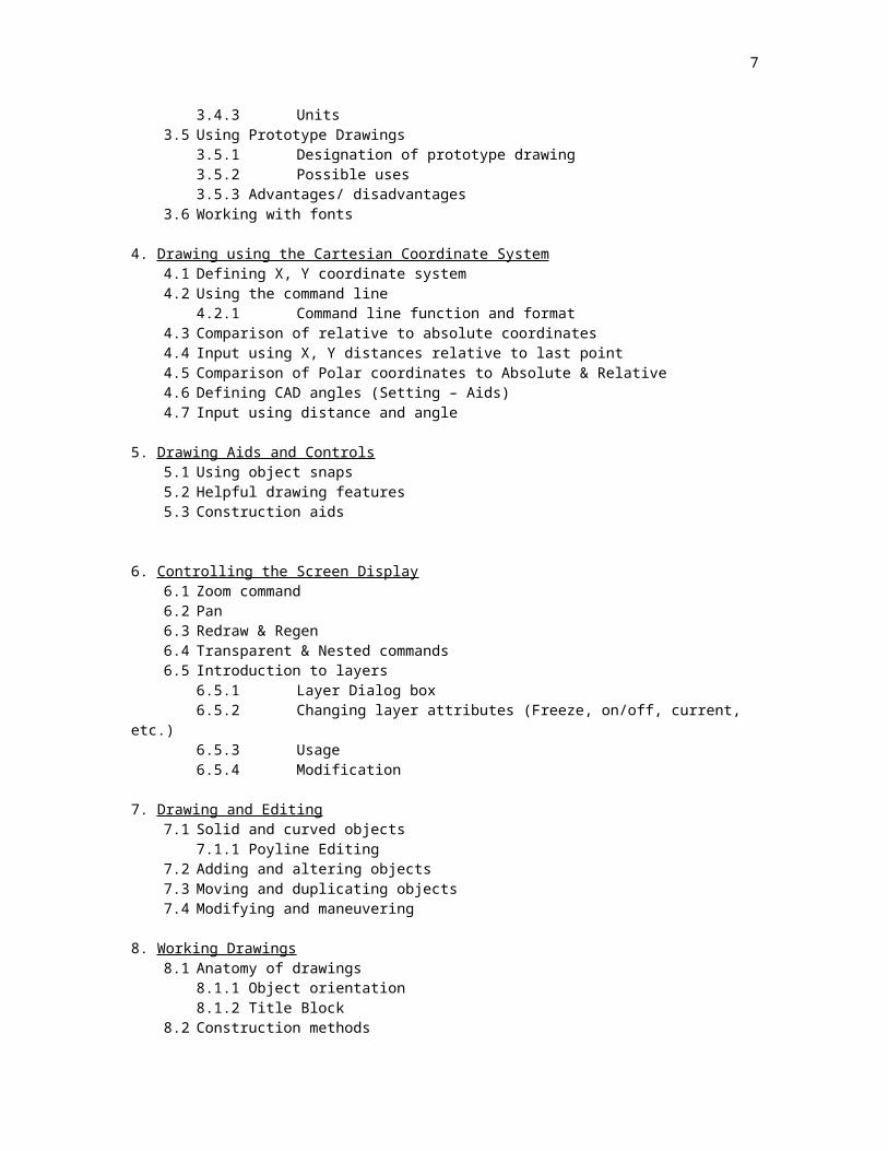
3.4.1 Standard settings3.4.2 Limits/Drawing Size3.4.3 Units
3.5 Using Prototype Drawings3.5.1 Designation of prototype drawing3.5.2 Possible uses3.5.3 Advantages/ disadvantages
3.6 Working with fonts
4. Drawing using the Cartesian Coordinate System4.1 Defining X, Y coordinate system4.2 Using the command line
4.2.1 Command line function and format4.3 Comparison of relative to absolute coordinates4.4 Input using X, Y distances relative to last point4.5 Comparison of Polar coordinates to Absolute & Relative4.6 Defining CAD angles (Setting – Aids)4.7 Input using distance and angle
5. Drawing Aids and Controls5.1 Using object snaps5.2 Helpful drawing features5.3 Construction aids
6. Controlling the Screen Display6.1 Zoom command6.2 Pan6.3 Redraw & Regen6.4 Transparent & Nested commands6.5 Introduction to layers
5
6.5.1 Layer Dialog box6.5.2 Changing layer attributes (Freeze, on/off, current, etc.)6.5.3 Usage6.5.4 Modification
7. Drawing and Editing7.1 Solid and curved objects
7.1.1 Poyline Editing7.2 Adding and altering objects7.3 Moving and duplicating objects7.4 Modifying and maneuvering
8. Working Drawings8.1 Anatomy of drawings
8.1.1 Object orientation8.1.2 Title Block
8.2 Construction methods
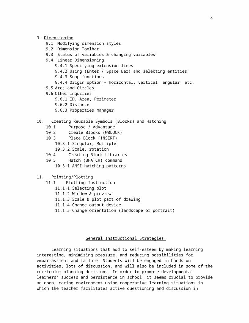
9. Dimensioning9.1 Modifying dimension styles9.2 Dimension Toolbar9.3 Status of variables & changing variables9.4 Linear Dimensioning
9.4.1 Specifying extension lines9.4.2 Using (Enter / Space Bar) and selecting entities9.4.3 Snap functions9.4.4 Origin option – horizontal, vertical, angular, etc.
9.5 Arcs and Circles9.6 Other Inquiries
9.6.1 ID, Area, Perimeter9.6.2 Distance9.6.3 Properties manager
10. Creating Reusable Symbols (Blocks) and Hatching10.1 Purpose / Advantage10.2 Create Blocks (WBLOCK)10.3 Place Block (INSERT)
10.3.1 Singular, Multiple10.3.2 Scale, rotation
10.4 Creating Block Libraries10.5 Hatch (BHATCH) command
10.5.1 ANSI hatching patterns
11. Printing/Plotting11.1 Plotting Instruction
11.1.1 Selecting plot11.1.2 Window & preview11.1.3 Scale & plot part of drawing11.1.4 Change output device11.1.5 Change orientation (landscape or portrait)
General Instructional Strategies
6
Learning situations that add to self-esteem by making learning interesting, minimizing pressure, and reducing possibilities for embarrassment and failure. Students will be engaged in hands-on activities, lots of discussion, and will also be included in some of the curriculum planning decisions. In order to promote developmental learners’ success and persistence in school, it seems crucial to provide an open, caring environment using cooperative learning situations in which the teacher facilitates active questioning and discussion in pursuit of identified goals. Tasks that are meaningful and stimulating to the students need to be structured to assure success with reasonable effort. It also seems to be particularly important that the teacher should serve as a model of an active, enthusiastic member of the learning community who values continuous, lifelong learning.
The CAD lab setting should not exceed 16 workstations due to inadequate coverage for effective learning to take place. If possible, the workstations should be oriented toward the instructor for monitoring student progress from a teaching vantage point. It is imperative that there be a means for the instructor to demonstrate CAD program fundamentals. This can be accomplished by means of an LCD projector or a software program that allows the teacher workstation to be displayed on student terminals. There should never be an enrollment situation where students must share workstations in a team setting. This would dramatically decrease the effectiveness of learning skills.
It is important that the latest software upgrades and licensing agreement are in place and checked annually. It would also be beneficial to inventory and check frequently supplies such as printer cartridges, printer paper, and any plotting pens if used. The annual department budget should include ample supplies for a maximum number of students in the CAD classes.
The activities that support the CAD curriculum should most definitely be hands on in nature. The activities should include commence with a basic drafting skills foundation for those students that have never been exposed to a drafting class (although in many cases, this is a requirement for CAD classes). The projects should as closely as possible, represent drawings that would need to be drafted in an industrial setting. These should be inclusive of both mechanical and architectural drawings. There may be situations where field trips to local businesses that utilize CAD would be helpful in making connections to the curriculum. Seeing CAD used in real life is a wonderful way to correlate classroom instruction to real life experiences.
7
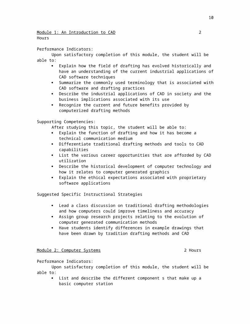
Module 1: An Introduction to CAD 2 Hours
Performance Indicators:Upon satisfactory completion of this module, the student will be able to: Explain how the field of drafting has evolved historically and have an understanding
of the current industrial applications of CAD software techniques Summarize the commonly used terminology that is associated with CAD software
and drafting practices Describe the industrial applications of CAD in society and the business implications
associated with its use Recognize the current and future benefits provided by computerized drafting methods
Supporting Competencies:After studying this topic, the student will be able to: Explain the function of drafting and how it has become a technical communication
medium Differentiate traditional drafting methods and tools to CAD capabilities List the various career opportunities that are afforded by CAD utilization Describe the historical development of computer technology and how it relates to
computer generated graphics Explain the ethical expectations associated with proprietary software applications
Suggested Specific Instructional Strategies
Lead a class discussion on traditional drafting methodologies and how computers could improve timeliness and accuracy
Assign group research projects relating to the evolution of computer generated communication methods
Have students identify differences in example drawings that have been drawn by tradition drafting methods and CAD
Module 2: Computer Systems 2 Hours
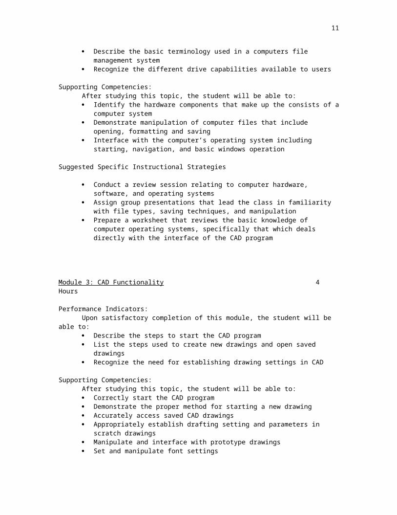
Performance Indicators:Upon satisfactory completion of this module, the student will be able to: List and describe the different component s that make up a basic computer station Describe the basic terminology used in a computers file management system Recognize the different drive capabilities available to users
Supporting Competencies:After studying this topic, the student will be able to: Identify the hardware components that make up the consists of a computer system Demonstrate manipulation of computer files that include opening, formatting and
saving Interface with the computer’s operating system including starting, navigation, and
basic windows operation
Suggested Specific Instructional Strategies
Conduct a review session relating to computer hardware, software, and operating systems
Assign group presentations that lead the class in familiarity with file types, saving techniques, and manipulation
Prepare a worksheet that reviews the basic knowledge of computer operating systems, specifically that which deals directly with the interface of the CAD program
8
Module 3: CAD Functionality 4 Hours
Performance Indicators:Upon satisfactory completion of this module, the student will be able to: Describe the steps to start the CAD program List the steps used to create new drawings and open saved drawings Recognize the need for establishing drawing settings in CAD
Supporting Competencies:After studying this topic, the student will be able to: Correctly start the CAD program Demonstrate the proper method for starting a new drawing Accurately access saved CAD drawings Appropriately establish drafting setting and parameters in scratch drawings Manipulate and interface with prototype drawings Set and manipulate font settings
Suggested Specific Instructional Strategies
Class demonstrations, discussions, and questioning Assign basic CAD program activities that involve opening a new drawing, setting
parameters and drafting settings, and saving to file Discussion on the industrial applications of CAD where drawing settings would need
to be tailored to fit the application (e.g. architectural vs. manufacturing) Provide students with a list of drawing parameters that must be set in a new drawing
and have them set up the drawing accordingly
Module 4: Drawing Using the Cartesian Coordinate System 4 Hours
Performance Indicators:Upon satisfactory completion of this module, the student will be able to: Describe the application of the coordinate system as it relates to the CAD
environment List the component that make up the Cartesian System Describe the function of the command line Recognize the need for using coordinates in CAD
Supporting Competencies:After studying this topic, the student will be able to: Correctly identify the X,Y,and Z coordinate axis Demonstrate proper utilization of the command line functions Compare and contrast absolute, relative, and polar coordinates Accurately define command line functions for setting angular line construction Manipulate and interface with prototype drawings Correctly input distance and angle data

9
Suggested Specific Instructional Strategies Class demonstrations, discussions, and questioning Assign drawing exercises that reinforce skills established Establish a wall chart with examples of the coordinate system and applications Provide students with sample command line data that reinforces the different
applications used
Module 5: Drawing Aids and Controls 2 Hours
Performance Indicators:Upon satisfactory completion of this module, the student will be able to: Explain the need for drawing aids in the CAD environment List the different object snaps that are available in CAD Describe the features of CAD specifically designed to aid the draftsperson Recognize the need for construction aids in CAD
Supporting Competencies:After studying this topic, the student will be able to: Correctly identify the different drawing aids available in CAD Load and place the object snap toolbar Demonstrate proper utilization of the object snap toolbar and functions Appropriately define and use construction lines and techniques
Suggested Specific Instructional Strategies Class demonstrations, discussions, and questioning Assign drawing exercises that Require the use of drawing aids Using CAD, have the students draw the object snap toolbar
Module 6: Controlling the Screen Display 4 Hours
Performance Indicators:Upon satisfactory completion of this module, the student will be able to: Explain the necessity for screen variation while using the CAD program List the tool functions that control the screen display Describe the need for redrawing and regenerating drawings Recognize the need for using layers in CAD
Supporting Competencies:After studying this topic, the student will be able to: Correctly identify the zoom command function on the CAD toolbar Demonstrate proper utilization of the pan function Compare and contrast redraw and regen functions in CAD drawings Accurately define the applications of layers Correctly access, set parameters for, and utilize layer functions
Suggested Specific Instructional Strategies Class demonstrations, discussions, and questioning Provide students with a drawing that requires screen modification to view different
portions of the drawing Assign sample drawing that require regeneration modifications Assign drawing exercises that require a variety of different layers
Module 7: Drawing and Editing 20 Hours
10
Performance Indicators:Upon satisfactory completion of this module, the student will be able to: State situations where changes in object position and shape are required Utilize CAD to produce solid and curved objects Use modify tool functions to move and manipulate objects Add and alter the geometry of objects Describe polyline editing
Supporting Competencies:After studying this topic, the student will be able to: Correctly construct solid and curved objects Demonstrate proper methods for adding and altering the geometry of objects Utilize the modify toolbar as required to perform their intended function Modify and maneuver object as dictated by the scope of the drawing Accurately create and edit polylines
Suggested Specific Instructional Strategies Class demonstrations, discussions, and questioning Assign drawing exercises that requires p-line creation and editing Assign drawings with fillets, chamfers, and other commonly used geometric
characteristics found in the modify toolbar Provide students with sample objects that require mirroring, moving, and offsetting
Module 8: The Working Drawing 20 Hours
Performance Indicators:Upon satisfactory completion of this module, the student will be able to: Use acquired skill and knowledge to complete a drawing from scratch Orient drawn objects in a suitable manner for application Explain the role of a title block Apply appropriate construction methods to CAD designs and drawings
Supporting Competencies:After studying this topic, the student will be able to: Accurately construct a working drawing from scratch using CAD tools Demonstrate proper drawing orientation to meet the needs of the application Properly format and implement a title block that contains all pertinent information Apply drawing construction methods that are appropriate to any given application
Suggested Specific Instructional Strategies Assign drawing problems that engage the students in practical applications of the
knowledge and skills acquired though instruction, demonstrations, and assignments Have students format and save a master title block template in ANSI A, B, and C
sizes
11
Module 9: Dimensioning 2 Hours
Performance Indicators:Upon satisfactory completion of this module, the student will be able to: Describe the communication that dimensioning provides Explain the dimension modifications that different drawing types require Dimension drawings based on standard drawing convention Perform geometric inquires as provided by program functions
Supporting Competencies:After studying this topic, the student will be able to: Correctly access and load dimension functions to the CAD environment Appropriately modify the dimension properties based on drawing requirements Utilize the dimension toolbar to accurately notate drawings Notate dimensions as dictated by ANSI standards Utilize inquire functions to correctly identify geometric properties
Suggested Specific Instructional Strategies Class demonstrations, discussions, and questioning Assign drawing exercises that requires dimension modification and application
Module 7: Drawing and Editing 20 Hours
Performance Indicators:Upon satisfactory completion of this module, the student will be able to: State situations where changes in object position and shape are required Utilize CAD to produce solid and curved objects Use modify tool functions to move and manipulate objects Add and alter the geometry of objects Describe polyline editing
Supporting Competencies:After studying this topic, the student will be able to: Correctly construct solid and curved objects Demonstrate proper methods for adding and altering the geometry of objects Utilize the modify toolbar as required to perform their intended function Modify and maneuver object as dictated by the scope of the drawing Accurately create and edit polylines
Suggested Specific Instructional Strategies Class demonstrations, discussions, and questioning Assign drawing exercises that requires p-line creation and editing Assign drawings with fillets, chamfers, and other commonly used geometric
characteristics found in the modify toolbar Provide students with sample objects that require mirroring, moving, and offsetting
Bibliography
Grabowski, R. (2001). Using AutoCAD 2002. Clifton Park, NY: Delmar Learning
12
Grabowski, R. (2003). Using AutoCAD 2004: basics. Clifton Park, NY: Delmar Learning
Finkelstein, E. (2001). AutoCAD 2002 bible. Hoboken, NJ: John Wiley & Sons
Finkelstein, E. (2003). AutoCAD 2004 bible. Hoboken, NJ: John Wiley & Sons
French, T., Svenson, C., Helsel, J., & Urbanick, B. (1997). Mechanical drawing: CAD- communications. New York, NY: Glencoe McGraw-Hill
French, T., Helsel, J. (2003). Mechanical drawing: board & CAD techniques. New York, NY: Glencoe McGraw-Hill
Shumaker, T. M., & Madsen, M. A. (2001). AutoCAD and its applications. Tinley Park, Ill.: The Goodheart-Wilcox Company, Inc.
Sykes, T. (2001). AutoCAD 2002: one step at a time. Upper Saddle River, NJ: Prentice Hall
Sykes, T. (2003). AutoCAD 2004: one step at a time, Part 1. Address unknown: The Forager (this is an e-book published by The Forager using Adobe Reader)
Tickoo, S. (2001). AutoCAD 2002: a problem-solving approach. Clifton Park, NY: Delmar Learning
Tickoo, S. (2003). AutoCAD 2004: a problem-solving approach. Clifton Park, NY: Delmar Learning
Walker, J., & Mathis, B. (2003). Exploring drafting: fundamentals of drafting technology. Tinley Park, Ill.: The Goodheart-Wilcox Company, Inc.
Wohlers, T. (2000). Applying AutoCAD 2000: a step by step approach. New York, NY: Glencoe McGraw-Hill
13
DVD, VHS, and Other Instructional Technology Resources
DVD Format
Netwind Learning Center - http://www.netwind.com/html/autocad-training.html
AutoCAD 2002 2D CD-ROM - Basics 4.5 Hours $99.95AutoCAD 2002 2D CD-ROM – Advanced 5.5 hours $99.95
Edulearn - http://www.youlearn.com/products/lk-products/A/autocad2004/autocad2004.html
AutoCAD 2004 Computer Based Training 16+ Hours $99.00AutoCAD 2002 Computer Based Training 16+ Hours $147.00AutoCAD 2000 CBT + 1 Video 16+ Hours $385.00
SofTutor® for AutoCAD 2004 2D - http://www.nvsi.com/acad.html - AutoCADInteractive Video 7 Hours $238.00SofTutor® for AutoCAD 2004 2D Interactive Video 5 Hours $104.00
VHS Video
On With Learning, Inc. - http://videoed.com/c2104.htmlAutoCAD 2000 Video Series 13.5 Hours $440.00
14
Appendices
General Web Resources
Academy of Applied Science (AAS)American Association for the Advancement of ScienceAmerican Chemical Society (ACS)American Society of Mechanical Engineers (ASME) ASEE EngineeringK12 CenterAssociation for Career and Technical Education (ACTE)Council on Technology Teacher Education (CTTE)Dr. Waite's SUNY Oswego Academic Web SiteEinstein ProjectElectronic Industries FoundationEpsilon Pi Tau Honorary Fraternity in TechnologyFlorida Technology Education AssociationFor Inspiration and Recognition of Science and Technology (FIRST)Four County Technology Association (Rochester Area)Future Scientists and Engineers of America (FSEA)History of Education - Selected Moments of 20th CenturyHistory of Science SocietyInner AutoInnovation Curriculum Online NetworkInstitute for Electrical and Electronic Engineers (IEEE)International Society for Technology in EducationInternational Technology Education AssociationJETSJournal of Technology EducationJournal of Technology EducationKISS Institute for Practical Robotics (KIPR)Microsoft Educator ResourcesMohawk Valley Technology Education AssociationMontgomery Public SchoolsNASA - Education ProgramNassau Technology Educators AssociationNational Academy of EngineeringNational Academy of Engineering: TECHNICALLY SPEAKINGNational Aeronautics and Space Administration (NASA)National Renewable Energy Laboratory (NREL)National Research CouncilNational Science FoundationNational Society of Professional EngineersNew York State Technology Education AssociationNiagara County & Western New York TEAOhio State UniversityOswego Technology Education AssociationProject Lead The WaySills USA Society for Philosophy and TechnologySociety for the History of TechnologySuffolk Technology Education Association

15
SUNY Oswego Dept of TechnologyTeacher Certification Office NYSTECH CORPSTech LearningTechne JournalTechnology for All Americans Project (standards)Technology Student AssociationTechnology Student Association (TSA)The Learning Institute of Technology Education (LITE)TIES MagazineU.S. Department of Education
Specific Web Resources
American Design Drafting Assn.: http://www.adda.org/
AutoDesk, Inc.: http://www.autodesk.com/autocad
CADALYST: http://www.cadonline.com
CADENCE Journal: http://www.cadenceweb.com
Computer-Aided Engineering: http://www.penton.com
Computer Graphics World: http://www.cgw.com
SkillsUSA (VICA): http://www.skillsusa.org/
16
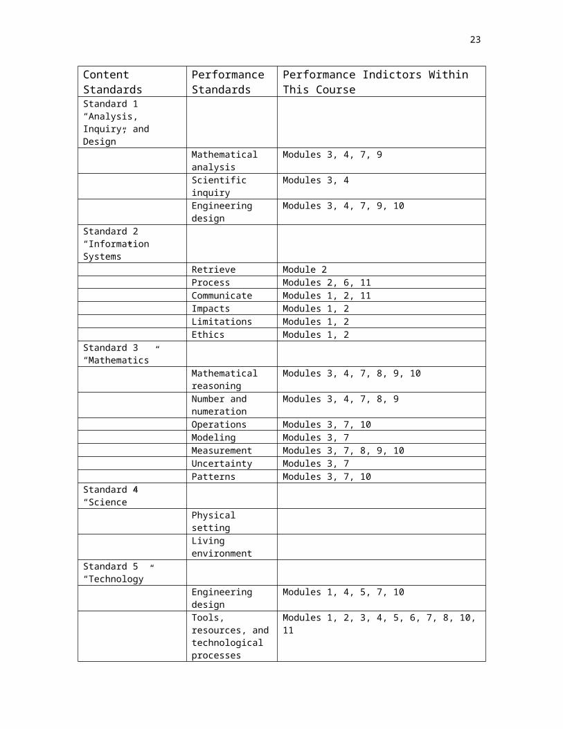
Appendix A - Correlation Matrix with NYS Learning Standards for Math, Science, and Technology (Complete text of standards available on line at: www.emsc.nysed.gov Go to MST icon)
Content Standards Performance Standards
Performance Indictors Within This Course
Standard 1“Analysis, Inquiry, and Design”
Mathematical analysis
Modules 3, 4, 7, 9
Scientific inquiry Modules 3, 4Engineering design Modules 3, 4, 7, 9, 10
Standard 2“Information Systems”
Retrieve Module 2Process Modules 2, 6, 11Communicate Modules 1, 2, 11Impacts Modules 1, 2Limitations Modules 1, 2Ethics Modules 1, 2
Standard 3“Mathematics”
Mathematical reasoning
Modules 3, 4, 7, 8, 9, 10
Number and numeration
Modules 3, 4, 7, 8, 9
Operations Modules 3, 7, 10Modeling Modules 3, 7 Measurement Modules 3, 7, 8, 9, 10Uncertainty Modules 3, 7Patterns Modules 3, 7, 10
Standard 4“Science”
Physical settingLiving environment
Standard 5“Technology”
Engineering design Modules 1, 4, 5, 7, 10Tools, resources, and technological processes
Modules 1, 2, 3, 4, 5, 6, 7, 8, 10, 11
Computer technology
Modules 1, 2, 3, 4, 5, 6, 7, 8, 10, 11
Technological systems
Module 2
History of technology
Module 1
Impacts Module 1Management Module 2

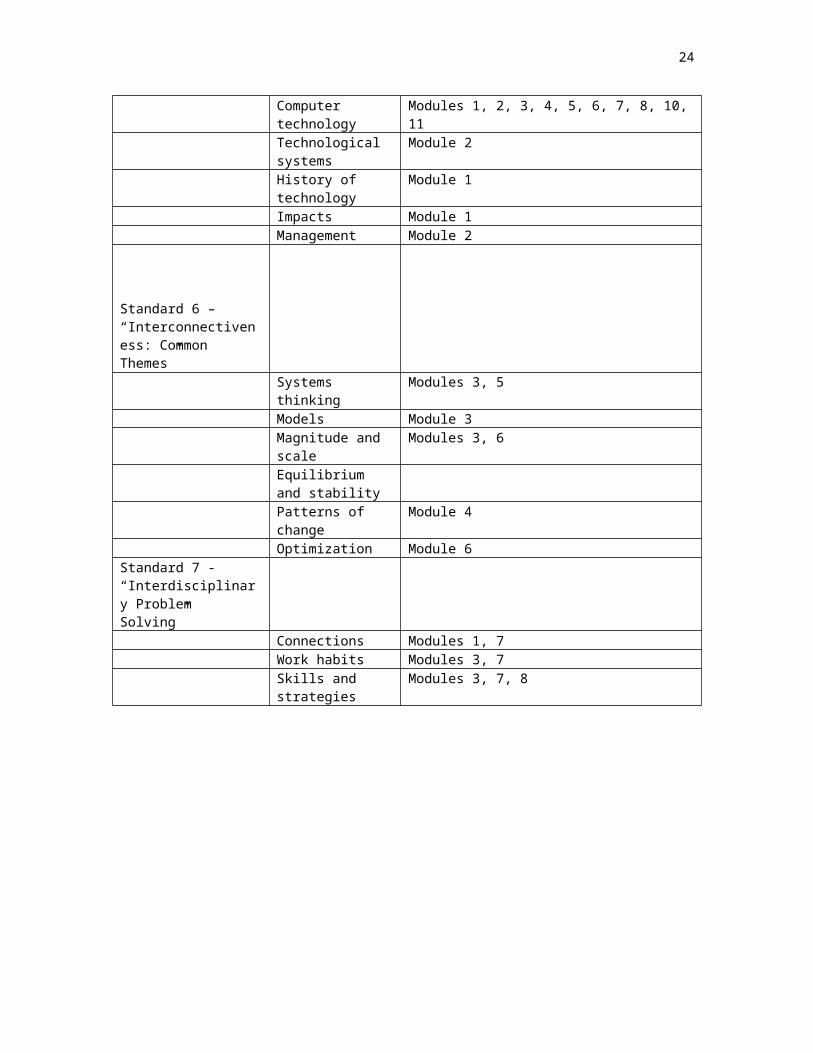
17
Standard 6 – “Interconnectiveness: Common Themes”
Systems thinking Modules 3, 5Models Module 3Magnitude and scale
Modules 3, 6
Equilibrium and stabilityPatterns of change Module 4Optimization Module 6
Standard 7 - “Interdisciplinary Problem Solving”
Connections Modules 1, 7Work habits Modules 3, 7Skills and strategies
Modules 3, 7, 8

18
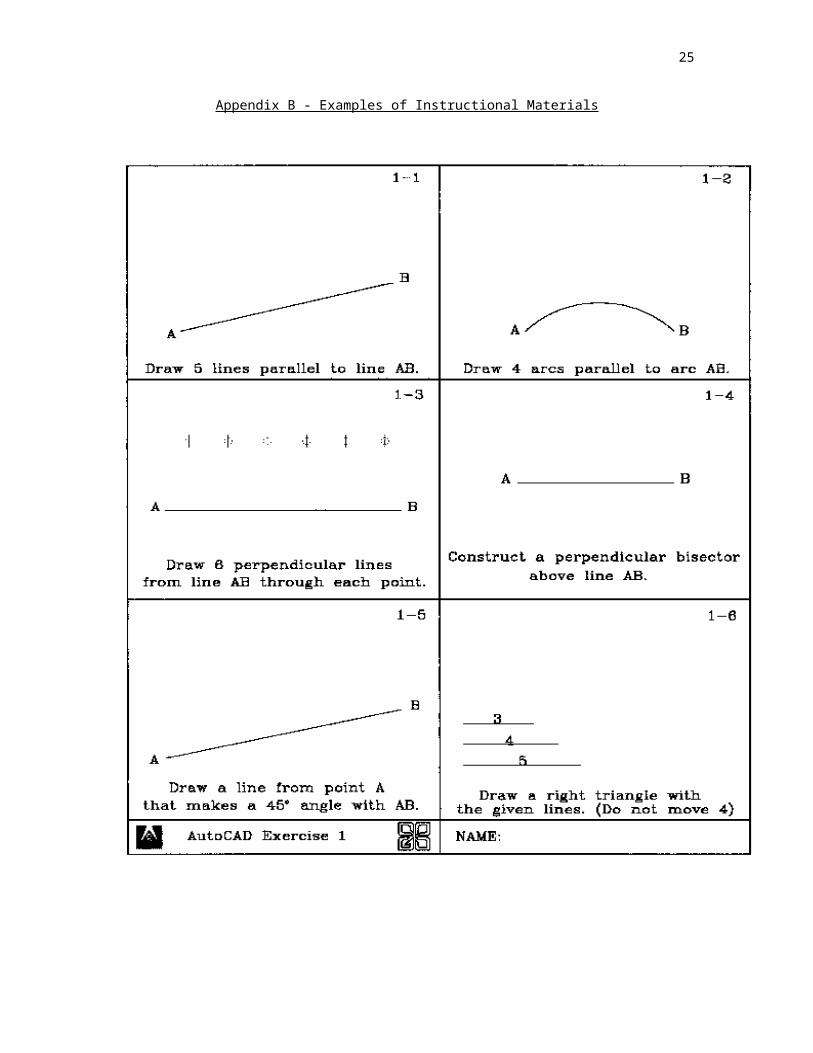
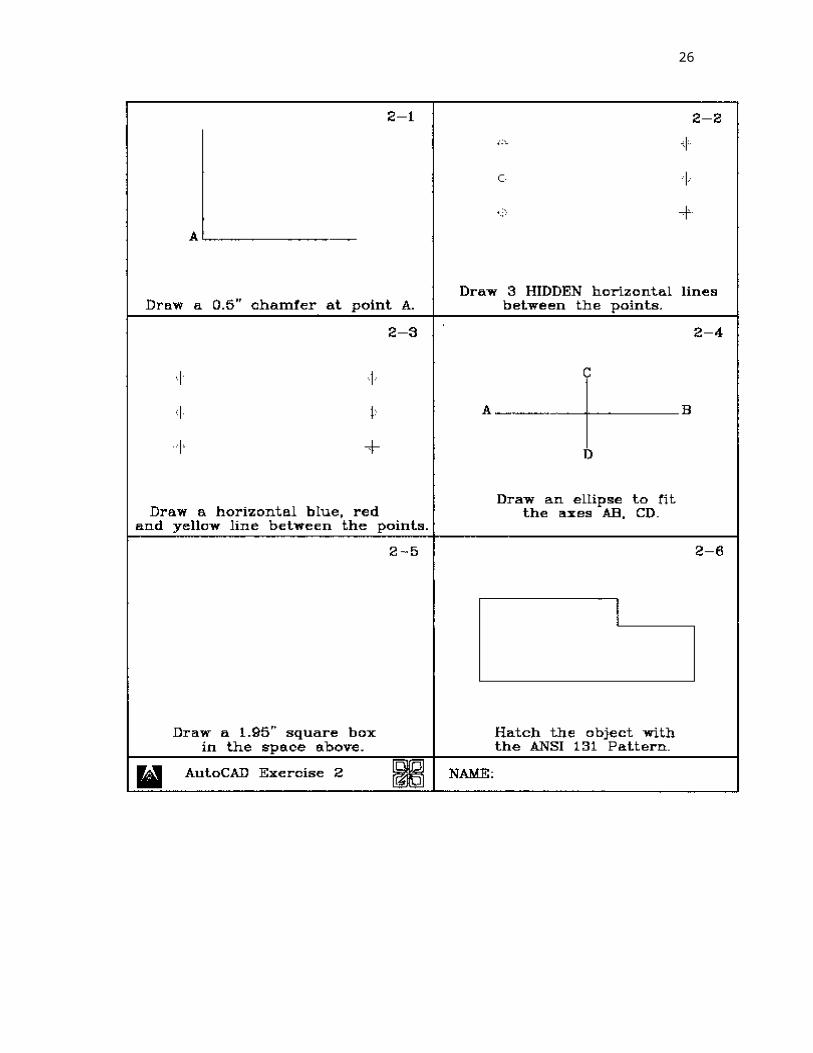
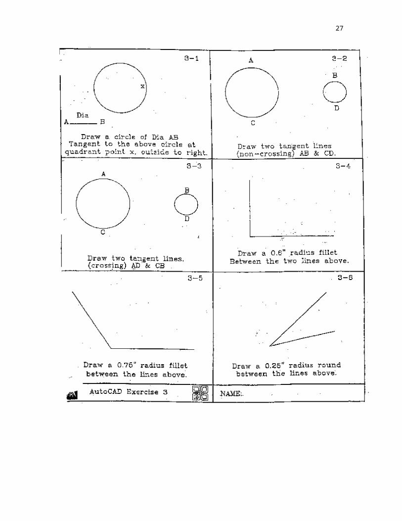
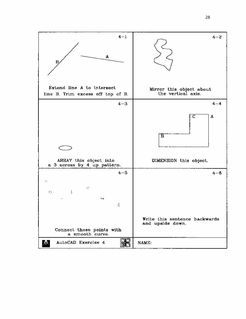
Appendix B - Examples of Instructional Materials

19

20

21

22
Appendix C - Examples of Assessment Materials
Computer Assisted Drawing - Sample Final Examination
DIRECTIONS: Choose the BEST answer for each of the following multiple-choice questions or statements.
1. To move a floating toolbar, you should:A. Click the X in the upper right corner of the toolbar.B. Pick the top of the toolbar and drag it to a new locationC. Move the pointer to the edge of the toolbar until a double arrow appears
and then drag it to a new locationD. Position the cursor over the toolbar, right-click, and select MOVE from the
list of options.
2. From which pull-down menu can you open a drawing file?A. FileB. EditC. DrawD. View
3. To re-enter the most recently used command:A. Type the letter R and press ENTER.B. Press CTRL E.C. Type EN and press ENTER.D. Press the space bar.
4. The POLYGON command:A. Is used to create any type of polygon.B. Allow you to create regular polygons only.C. Contains Octagon and Pentagon options.D. Is limited to creating polygons of 12 or fewer sides.
5. The ERASE command:A. Erases selected parts of an object.B. Clears the entire screen using the ERASE CLEAR option.C. Erases selected objects.D. Automatically erases all objects from the drawing file.
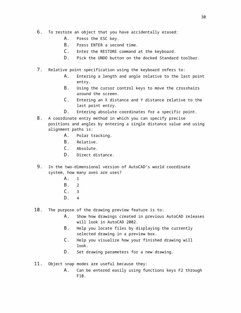
6. To restore an object that you have accidentally erased:A. Press the ESC key.B. Press ENTER a second time.C. Enter the RESTORE command at the keyboard.D. Pick the UNDO button on the docked Standard toolbar.
7. Relative point specification using the keyboard refers to:A. Entering a length and angle relative to the last point entry.B. Using the cursor control keys to move the crosshairs around the screen.C. Entering an X distance and Y distance relative to the last point entry.
23
D. Entering absolute coordinates for a specific point.8. A coordinate entry method in which you can specify precise positions and angles by
entering a single distance value and using alignment paths is:A. Polar tracking.B. Relative.C. Absolute.D. Direct distance.
9. In the two-dimensional version of AutoCAD’s world coordinate system, how many axes are uses?
A. 1B. 2C. 3D. 4
10. The purpose of the drawing preview feature is to:A. Show how drawings created in previous AutoCAD releases will look in
AutoCAD 2002.B. Help you locate files by displaying the currently selected drawing in a
preview box.C. Help you visualize how your finished drawing will look.D. Set drawing parameters for a new drawing.
11. Object snap modes are useful because they:A. Can be entered easily using functions keys F2 through F10.B. Dimension the drawing as you specify the modes.C. Allow you to snap to points that you otherwise could not reach easily and
accurately.D. None of the above.
12. To use the CENTER-OBJECT-SNAP, you choose the center of the circle by picking:A. A point as close to the center of the circle as possible.B. Two points on the circle to establish toe diameter, from which the center
can be calculated using the midpoint object snap.C. Anywhere inside the boundary of the circle.D. A point on the circle itself.
13. ZOOM PREVIOUS:A. Restores the original view of the drawing.B. Restores the previous zoom magnification of the drawing.C. Displays the drawing boundaries defined by the LIMITS command.D. Both B and C.
14. AutoCAD’s aerial view:A. Provides a quick and easy method of zooming and panning.B. Shows the size and position of the current zoom window relative to the
entire drawing area.C. Allow you to zoom quickly to a portion of the drawing that you define
using the Aerial View’s view box.
24
D. All of the above.
15. Which of the following objects is not affected by the FILL command?A. SolidB. MultilineC. TextD. Wide polyline
16. The STYLE command:A. Is used to develop new text styles.B. Is used in conjunction with the TEXTQLTY command.C. Both A and B.D. Neither A nor B.
17. The THROUGH option of the OFFSET command allows you to create a line:A. Perpendicular to the original line through a point you specify.B. From the current endpoint of the line through a point, you specify.C. Parallel to the original line through a point you specifyD. Parallel to the original line through the origin (0,0).
18. With the STRETCH command, you can:A. Lengthen objects both horizontally and vertically.B. Stretch a circle to form an egg-shaped object.C. Maintain the current proportions of an object while lengthening one end of
it.D. Both A and B.
19. Which of the following commands would you most likely use to remove line segments drawn too far past an intersecting line?
A. TRIMB. EXTENDC. STRETCHD. ERASE
20. To create a paragraph of text that can be edited as a single object, use the:A. MTEXT command.B. TEXT command.C. DTEXT command.D. EDITTEXT command.
21. You can recognize TrueType fonts in AutoCAD’s list of fonts by:A. Their TTX extension.B. The AutoCAD symbol to the left of the font name.C. The overlapping T’s to the left of the font nameD. The asterisk (*) that follows the font name.
22. You can correct text using the:A. DDEDIT command.B. MTPROP command.
25
C. DTEXT command.D. Both A and B.
23. The easiest way to insert the degree symbol (°) into an MTEXT object is to:A. Minimize AutoCAD, pick the Windows Start button, select Accessories
and Character Map, choose the degree symbol and copy it to the clipboard.
B. Pick the Symbol drop-down box and choose Degrees %%d.C. Pick the Layers icon and create a layer that has a text style called
Symbols: use that layer for all symbols, including the degree symbol.D. Use the CTRL + SHIFT + D combination.
24. The AutoCAD hatch feature:A. Provides a selection of four hatch patterns.B. Is issued with the PATTERN command.C. Always hatches over the top of text when text is located inside the object
to be hatched.D. None of the above.
25. The Hatch Pattern Palette presents:A. Graphic examples of hatches that conform to ANSI and ISO standards.B. A master list of colors available for hatch patterns in AutoCAD.C. A workspace in which you can create new hatch patterns.D. All of the above.
26. An AutoCAD drawing template file usually consists of:A. A completed drawing, except for dimensions.B. Numerous mode settings and drawing parameters stored in an audit
report file.C. Pre-established settings for units, grid, snap, and drawing area.D. Both B and C.
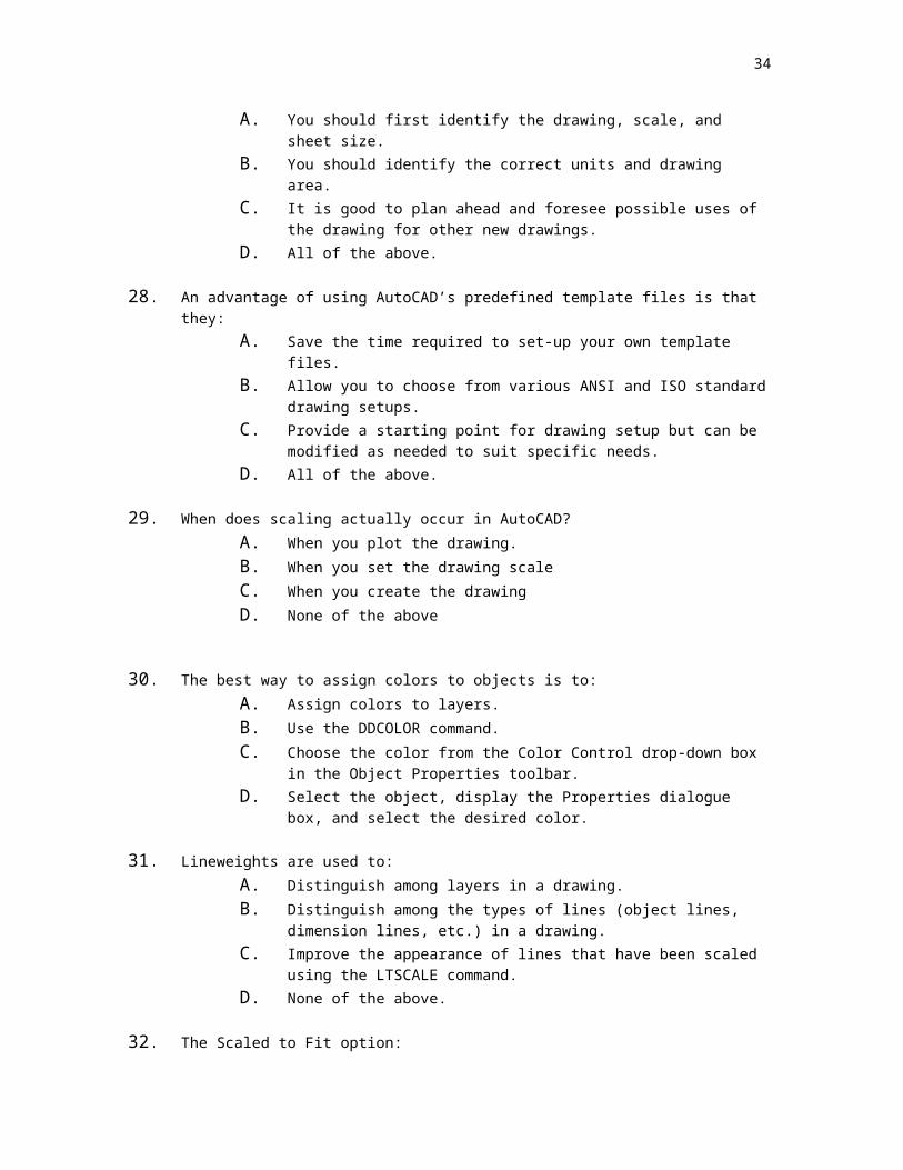
27. When beginning a new drawing template:A. You should first identify the drawing, scale, and sheet size.B. You should identify the correct units and drawing area.C. It is good to plan ahead and foresee possible uses of the drawing for
other new drawings.D. All of the above.
28. An advantage of using AutoCAD’s predefined template files is that they:A. Save the time required to set-up your own template files.B. Allow you to choose from various ANSI and ISO standard drawing setups.C. Provide a starting point for drawing setup but can be modified as needed
to suit specific needs.D. All of the above.
29. When does scaling actually occur in AutoCAD?A. When you plot the drawing.B. When you set the drawing scale
26
C. When you create the drawingD. None of the above
30. The best way to assign colors to objects is to:A. Assign colors to layers.B. Use the DDCOLOR command.C. Choose the color from the Color Control drop-down box in the Object
Properties toolbar.D. Select the object, display the Properties dialogue box, and select the
desired color.
31. Lineweights are used to:A. Distinguish among layers in a drawing.B. Distinguish among the types of lines (object lines, dimension lines, etc.) in
a drawing.C. Improve the appearance of lines that have been scaled using the
LTSCALE command.D. None of the above.
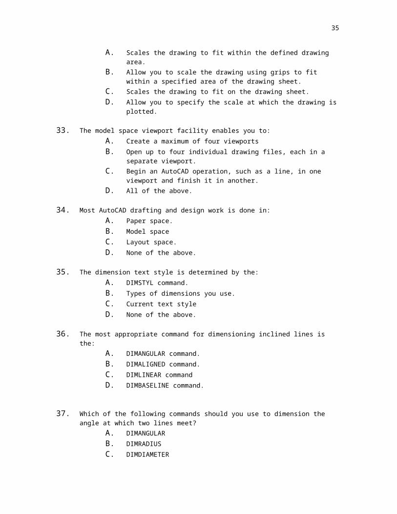
32. The Scaled to Fit option:A. Scales the drawing to fit within the defined drawing area.B. Allow you to scale the drawing using grips to fit within a specified area of
the drawing sheet.C. Scales the drawing to fit on the drawing sheet.D. Allow you to specify the scale at which the drawing is plotted.
33. The model space viewport facility enables you to:A. Create a maximum of four viewportsB. Open up to four individual drawing files, each in a separate viewport.C. Begin an AutoCAD operation, such as a line, in one viewport and finish it
in another.D. All of the above.
34. Most AutoCAD drafting and design work is done in:A. Paper space.B. Model spaceC. Layout space.D. None of the above.
35. The dimension text style is determined by the:A. DIMSTYL command.B. Types of dimensions you use.C. Current text styleD. None of the above.
36. The most appropriate command for dimensioning inclined lines is the:A. DIMANGULAR command.B. DIMALIGNED command.
27
C. DIMLINEAR commandD. DIMBASELINE command.
37. Which of the following commands should you use to dimension the angle at which two lines meet?
A. DIMANGULARB. DIMRADIUSC. DIMDIAMETERD. None of the above.
38. The Fit tab contains options that:A. Alter the dimension scale to fit the current drawing.B. Control the placement of dimension text and arrows when there is not
enough space to place them inside the extension lines.C. Alter the size of the dimension text so that it fits between the extension
lines.D. Changes the size of the object to fit the specified dimension.
39. The array function used to place objects into columns and rows is called:A. Polar arrayB. Horizontal arrayC. Vertical arrayD. Rectangular array
40. Using the ______ tool will help you to remove overextended ends of a line.A. ChamferB. ExplodeC. TrimD. Hatch
41. A new line type can be loaded from:A. Properties dialogue boxB. Object snap dialogue boxC. Array dialogue boxD. Layers dialogue box
42. Properties of the dimensions can be set in the:A. Layers dialogue boxB. Dimension style dialogue boxC. Text style dialogue boxD. Hatch dialogue box
43. The sort cut that is used to UNDO the last command entered is:A. Ctrl UB. Ctrl LC. Ctrl ZD. Ctrl D
28
44. The zoom tool used when plotting a drawing is:A. Zoom allB. Zoom real timeC. Zoom extentsD. Zoom window
45. A scale factor of .25 will:A. Scale a drawing down to one-quarter of its original size.B. Increase the size of the drawing 25%C. Divide the screen into quartersD. Scale the drawing limits to 25%
46. Click the _____ button to change from model to paper space.A. PolarB. OrthoC. ModelD. Osnap
47. The size of a view port is manipulated in:A. Layout 1B. Model spaceC. Drawing limits dialogue boxD. Zoom scale dialogue box
48. To change the level of a line already drawn, you must:A. Select the new level then select the lineB. Select the line then select the new level.C. Delete the line and redraw it on the new levelD. Regenerate the viewport.
49. A quick way to develop new lines parallel to existing lines is to choose:A. Parallel commandB. Offset commandC. Construction line commandD. Array command
50. To change the scale of a line symbol you must select:A. Modify – PropertiesB. Modify – ScaleC. Modify – SymbolD. Modify – Object

29
Computer Aided Drawing Final Exam Answer Key
1. B2. A3. D4. B5. C6. D7. C8. A9. B10. B11. C12. D13. B14. D15. C16. A17. C18. A19. A20. A21. C22. A23. B24. D25. A
30
26. C27. D28. D29. A30. A31. B32. C33. C34. B35. D36. B37. A38. B39. D40. C41. A42. B43. A44. C45. A46. C47. B48. B49. B50. A

31
COMPUTER ASSISTED DRAWING EVALUATION
DRAWING MECHANICSSelection of views correct for part being drawn 5 4
3 2 1 0
View positions on drawing correct 5 4
3 2 1 0
Correct drawing scale used 5
0
Correct sheet size selected 5
0
Drawing centered in drawing space available on paper 5 4
3 2 1 0
All surfaces, edges, and features represented by the correct line symbols 5 4
3 2 1 0
Line widths correctly assigned 5 4
3 2 1 0
Line colors correctly assigned 5 4
3 2 1 0
Title block information correctly filled-in 5 4
3 2 1 0
DRAWING SOLUTIONCorrect drawing style used 5 4
3 2 1 0
Problem solved correctly (X3) 15
12 9 6 3
0
All edges, surfaces, and features shown on drawing (X2) 10 8
6 4 2 0
DIMENSIONS AND NOTATIONSDimensioning method used correct for drawing problem 5
0
Dimension style correct 5 4
3 2 1 0

32
All features dimensioned correctly 5 4
3 2 1 0
Total size for all 3 planes dimensioned and position correctly 5
3 1 0
All detail dimensions correctly positioned and stated 5 4
3 2 1 0
Dimension scale correct 5
0
Notes correctly positioned and stated 5 4
3 2 1 0
TOTAL SCORE
______ / 110
GRADE
__________5 = Excellent4 = Good (1 minor error)3 = Average (2 minor errors or 1 major error)2 = Poor (3 or more minor errors or 2 major errors)1 = Very poor (more than 2 major errors)0 = Missing from drawing or completely wrong
COMPUTER ASSISTED DRAWINGFINAL PROJECT EVALUATION – Part Drawings
DRAWING MECHANICSSelection of views correct for each part being drawn 5 4 3
2 1 0
View positions on drawing correct 5 4 3
2 1 0
Correct drawing scale used 5
0

33
Correct sheet size selected 5
0
Drawing centered in drawing space available on paper; logically laid out 5 4 3
2 1 0
All surfaces, edges, and features represented by the correct line symbols 5 4 3
2 1 0
Line widths correctly assigned 5 4 3
2 1 0
Line colors correctly assigned 5 4 3
2 1 0
Title block information correctly filled-in 5 4 3
2 1 0
DRAWING SOLUTIONCorrect drawing style used (Orthographic or pictorial) 5 4 3
2 1 0
Problem solved correctly (X3) 15 12 9
6 3 0
All edges, surfaces, and features shown on each drawing (X2) 10 8 6
4 2 0
DIMENSIONS AND NOTATIONSDimensioning method used correct for drawing problem (chain, baseline) 5
0
Dimension style correct (fractional, decimal) 5 4 3
2 1 0
All features for each part dimensioned correctly 5 4 3
2 1 0
Total size for all 3 planes dimensioned and position correctly for each part 5 3
1 0 All
detail dimensions correctly positioned and stated 5 4 3
2 1 0 NA
Dimension scale correct 5
0
Notes correctly positioned and stated 5 4 3
2 1 0
Each part dwg. titled with ¼ inch high Ariel font title centered under dwg. 5 3
0
34
Each part dwg. scale stated under title in 1/8 inch high Ariel font 5 3
0
DRAWING
_____/_____
ASSEMBLY
_____/_____
FINAL PROJECT SCORE
_____/_____
FINAL PROJECT GRADE
___________5 = Excellent4 = Good (1 minor error)3 = Average (2 minor errors or 1 major error)2 = Poor (3 or more minor errors or 2 major errors)1 = Very poor (more than 2 major errors)0 = Missing from drawing or completely wrong
35
COMPUTER ASSISTED DRAWINGFINAL PROJECT EVALUATION – Assembly Drawing
DRAWING MECHANICS
Correct views chosen for assembly drawing 5 3
0 NA
Views centered on sheet 5
0 NA
All parts visible on assembly 5 4 3 2 1
0 NA
Moving parts shown halfway through total movement 5 3
0 NA
Assembly correctly scaled 5
0 NA
Line widths correctly assigned 5 3
0 NA
Line colors correctly assigned 5 3
0 NA
All features represented by the correct line symbols 5 3
0 NA
ASSEMBLY DRAWING FEATURESParts numbered with balloons in correct order of assembly 5 3
0 NA
Balloons placed correctly 5 3
0 NA
Parts list shown on drawing 5
0 NA
All parts listed on parts list 5 3
0 NA
Part quantities listed correctly 5 3
0 NA
SCORE
_____ / 65

36
Appendix D - Students with Disabilities
The Board of Regents, through part 100 Regulations of the Commissioner, the Action Plan, and The Compact for Learning, has made a strong commitment to integrating the education of students with disabilities into the total school program. According to Section 100.2(s) of the Regulations of the “Commissioner of Education, “Each student with a handicapping condition as such term is defined in Section 200.1(ii) of this Chapter, shall have access to the full range of programs and services set forth in this Part to the extent that such programs and services are appropriate to such student’s special educational needs”. Districts must have policies and procedures in place to make sure that students with disabilities have equal opportunities to access diploma credits, courses, and requirements.
The majority of students with disabilities have the intellectual potential to master the curricula content requirements of a high school diploma. Most students who require special education attend regular education classes in conjunction with specialized instruction and/or related services. The students must attain the same academic standards as their non-disabled peers to meet graduation requirements, and, therefore, must receive instruction in the same content area, at all grade levels. This will ensure that they have the same informational base necessary to pass statewide testing programs and meet diploma requirements.
Teachers certified in the subject area should become aware of the needs of students with disabilities who are participating in their classes. Instructional techniques and materials must be modified to the extent appropriate to provide students with disabilities the opportunity to meet diploma requirements. Information or assistance is available through special education teachers, administrators, the Committee on Special Education (CSE) or student’s Individualized Education Program (IEP).
Strategies for Modifying Instructional Techniques and Materials.
1. Students with disabilities may use alternative testing techniques. The needed testing modification must be identified in the student’s Individualized Education Program (IEP). Both special and regular education teachers need to work in close cooperation so that the testing modifications can be used consistently throughout the student’s program.
2. Identify, define, and pre-teach key vocabulary. Many terms in this syllabus are specific, and some students with disabilities will need continuous reinforcement to learn them. It would be helpful to provide a list of these key words in the special education teacher in order to provide additional reinforcement in the special education setting.
3. Assign a partner for the duration of a unit to a student as an additional resource to facilitate clarification of daily assignments, timelines for assignments, and access to daily notes.
4. When assigning long-term projects or reports, provide a timeline with benchmarks as indicators for completion of major sections. Students who have difficulty with organizational skills and time sequence ma need to see completion of sections to maintain the organization of a lengthy project or report.
Infusing Awareness of Persons with Disabilities Through Curriculum.
In keeping with the concept of integration, the following subgoal of the Action Plan was established.

37
In all subject areas, revisions in the syllabi will include materials and activities related to generic subgoals, such as problem solving, reasoning skills, speaking, capacity to search for information, the use of libraries, and increasing student awareness of and information about the disabled.
The purpose of this subgoal is to ensure that appropriate activities and materials are available to increase student awareness of disabilities.
The curriculum, by design, includes information, activities, and materials regarding persons with disabilities. Teachers are encouraged to include other examples as may be appropriate to their classroom or the situation at hand.

38
Appendix E - Student Leadership Skills
Development of leadership skills is an integral part of occupational education in New York State. The New York State Education Department states “each education agency should provide to every student the opportunity to participate in student leadership development activities. All occupational education students should be provided the opportunity to participate in the educational activities of the student organization(s) which most directly relate(s) to their chosen educational program”.
Leadership skills should be incorporated in the New York state occupational education curricula to assist students to become better citizens with positive qualities and attitudes. Each individual should develop skills in communications, decision making/problem solving, human relations, management, and motivational techniques.
Leadership skill may be incorporated into the curricula as competencies (performance indicators) to be developed by every student or included within the suggested instructional strategies. Teachers providing instruction through occupational educational curricula should familiarize themselves with the competencies. Assistance may be requested from the State adviser of the occupational student organization related to the program area.
Students who elect to become active members in student leadership organizations chartered by NYSED have the advantage of the practical forum to practice leadership skills in an action-oriented format. They have the potential for recognition at the local, state, and national level.
More information in Technology Education can be found at the Technology Education Student Association web site at:
http://www.tsawww.org