VWHP &RGH˛)/67’0)& $ 9HUVLRQ9 0DQXDO - …€¢ programming of the configuration parameters and a...
56
S&2 6WDQGDUG$SSOLFDWLRQ 5HIULJHUDWLRQ6\VWHP &RGH)/67’0)&$ 9HUVLRQ90DQXDO
Transcript of VWHP &RGH˛)/67’0)& $ 9HUVLRQ9 0DQXDO - …€¢ programming of the configuration parameters and a...

S&26WDQGDUG$SSOLFDWLRQ
5HIULJHUDWLRQ6\VWHP&RGH)/67'0)&$9HUVLRQ90DQXDO


:HZLVKWRVDYH\RXWLPHDQGPRQH\:HFDQDVVXUH\RXWKDWWKHWKRURXJKUHDGLQJRIWKLVPDQXDOZLOOJXDUDQWHHFRUUHFWLQVWDOODWLRQDQGVDIHXVHRIWKHSURGXFWGHVFULEHG
,03257$17:$51,1*6
%()25( ,167$//,1*25+$1'/,1*7+($33/,$1&(3/($6(&$5()8//<5($'$1')2//2:7+(,16758&7,216'(6&5,%(',17+,60$18$/
7KHDSSOLDQFHWKDWWKLVVRIWZDUH LVGHGLFDWHGWRKDVEHHQGHYHORSHGWRRSHUDWHULVNIUHHDQGIRUDVSHFLILFSXUSRVHDVORQJDV• the software is installed, programmed, run and maintained according to the instructions in this manual and by qualified
personnel; • all the conditions prescribed in the installation and user manual of the appliance in question are respected. $OO RWKHU XVHV DQG PRGLILFDWLRQV PDGH WR WKH GHYLFH WKDW DUH QRW DXWKRULVHG E\ WKH PDQXIDFWXUHU DUH FRQVLGHUHGLQFRUUHFW/LDELOLW\IRULQMXU\RUGDPDJHFDXVHGE\WKHLQFRUUHFWXVHRIWKHGHYLFHOLHVH[FOXVLYHO\ZLWKWKHXVHU


&217(176
7+(352*5$0 1.1. Introduction.......................................................................................................................................................................1 1.2. General description ...........................................................................................................................................................1 1.3. Starting the machine .........................................................................................................................................................1
1.3.1. Initialising the parameters in the permanent memory ...............................................................................................1 1.3.2. Basic configuration ...................................................................................................................................................2
1.4. The supervisor network.....................................................................................................................................................3 1.4.1. Serial boards..............................................................................................................................................................3 1.4.2. Communication protocols. ........................................................................................................................................3
1.5. Meaning of the pCO² inputs / outputs. ..............................................................................................................................4
0$,16(77,1*6 2.1. Dead zone .........................................................................................................................................................................6
2.1.1. Proportional band......................................................................................................................................................6 2.2. Compressor management..................................................................................................................................................6
2.2.1. ON OFF compressor management, without inverter ................................................................................................7 2.2.2. Compressor management with inverter.....................................................................................................................7 2.2.3. Compressor parameters.............................................................................................................................................8 2.2.4. Compressor time settings ..........................................................................................................................................9
2.3. Fan management ...............................................................................................................................................................9 2.3.1. ON OFF fan management without inverter.............................................................................................................10 2.3.2. Fan management with inverter................................................................................................................................10 2.3.3. Fan parameters ........................................................................................................................................................10 2.3.4. Fan time settings .....................................................................................................................................................10
2.4. Special functions.............................................................................................................................................................11 2.4.1. Compressor time bands...........................................................................................................................................11 2.4.2. Force devices ..........................................................................................................................................................11 2.4.3. Auxiliary probe management..................................................................................................................................11
2.5. Alarm management.........................................................................................................................................................11
86(5,17(5)$&( 3.1. Display............................................................................................................................................................................14 3.2. LEDs under the buttons ..................................................................................................................................................14 3.3. External keypad ..............................................................................................................................................................14
3.3.1. Use of the buttons on the external terminal.............................................................................................................15 3.4. Built-in terminal..............................................................................................................................................................15
3.4.1. Use of the buttons on the Built-in terminal .............................................................................................................16 3.5. Tree layout of the screens. ..............................................................................................................................................16
3.5.1. MENU button branch..............................................................................................................................................16 3.5.2. MAINT button, maintenance branch ......................................................................................................................17 3.5.3. PRINTER button branch.........................................................................................................................................19 3.5.4. I/O button, input/output status branch.....................................................................................................................19 3.5.5. Clock branch ...........................................................................................................................................................21 3.5.6. SET button, set point branch...................................................................................................................................21 3.5.7. PROG button branch...............................................................................................................................................22 3.5.8. INFO button branch ................................................................................................................................................24 3.5.9. MENU+PROG buttons, unit configuration branch.................................................................................................24 3.5.10. ALARM button branch ...........................................................................................................................................30 3.5.11. ON/OFF button branch ...........................................................................................................................................32 3.5.12. Log branch ..............................................................................................................................................................32
S&2,167580(17$1'$&&(6625<&2'(6
3$5$0(7(5'(),1,7,217$%/(

3$5$0(7(57$%/(6 6.1. Default value...................................................................................................................................................................36 6.2. Variables for communication with the supervisor ..........................................................................................................37
6.2.1. Analogue variables..................................................................................................................................................37 6.2.2. Digital variables ......................................................................................................................................................37 6.2.3. Integer variables......................................................................................................................................................39
6.3. Examples.........................................................................................................................................................................41 6.3.1. Example of SMALL configuration .........................................................................................................................41 6.3.2. Example of MEDIUM configuration ......................................................................................................................42 6.3.3. Example of LARGE configuration .........................................................................................................................43
6.4. Possible configurations ...................................................................................................................................................45
FLSTDMFC0A pCO² refrigeration system
cod. Carel +030221991 rel. 1.0 dated 27/07/01 1
7+(352*5$0 ,QWURGXFWLRQ
This program allows the management of a refrigeration system, with the following characteristics: • display and control of the values measured; • management of between one and six compressors, depending on the number of outputs, with between zero and three
capacity-control steps each, and between one and five condensation stages; • configuration of the devices being controlled; • display of alarms by LCD display, and audible signal; • programming of the configuration parameters and a number of operating parameters with password-protected access; • availability of three levels of access to the parameter setting screens, controlled by three different passwords; • modification of the fundamental operating parameters (set point, differentials, alarm thresholds, time settings); • programming of the time bands, and control of the compressors with a second set point to allow energy savings in the set
time bands; • multi-language management • connection to a supervisor/telemaintenance serial line.
*HQHUDOGHVFULSWLRQThe purpose of this application is to control a refrigeration system in which the maximum configuration features the management of 6 compressors with 3 capacity-control steps, 5 fans and 2 controllers. The control is based on the readings from the two pressure probes connected to analogue inputs B1 and B2. The digital inputs on the pCO² board are connected to the alarm signals from the devices. The activation of the alarms is signalled on the display in the specific screens, and by a buzzer (only with the external terminal). The program features a number of screens for setting the operating values, and others for setting the machine configuration, all protected by password. There are three levels of access to the protected screens, each referring to different passwords:
level 1 User password (“user branch”): refers to a modifiable password, which allows access only to the setting of the control operating parameters.
Default value = 0
level 2 Service password (“service branch”): refers to a modifiable password, which allows access to the maintenance parameters.
Default value = 0
level 3 Manufacturer password (“manufacturer branch”): refers to a modifiable password which allows access to all the machine configuration screens, including the setting of a new user, service and manufacturer password and the entering of the default values
Default value = 1234
7DEOH There is a fixed password that accesses any branch and is set during programming: FIXED PASSWORD = 1234. ,03257$17:$51,1*to avoid tampering during the operation of the machine, only qualified personnel must know the manufacturer password. In particular, the manufacturer and fixed password are used in the preliminary phases of installation and when the setting screens protected by the other passwords cannot be accessed.
6WDUWLQJWKHPDFKLQH
,QLWLDOLVLQJWKHSDUDPHWHUVLQWKHSHUPDQHQWPHPRU\The first time that the pCO² is used the data in the permanent memory should be initialised to prevent the use of incorrect for the required control functions. For this reason, the first time the pCO² is used, and any time the software release is upgraded, the default values should be entered. This is performed automatically the fist time the program is run. To perform the same procedure at any other time, follow these steps: 1. Turn the pCO² on; after a certain time in which the check routine is run, the pCO² will display the main screen,
M_MAIN_MENU. During the first installation IGNORE the alarms, as these may be the result of incorrect data in the permanent memory.
2. Press the MENU + PROG buttons to display the password setting screen. This screen prevents access to the configuration branch by unauthorised persons.
3. Enter the password (default 1234), and press ENTER to confirm. 4. Move to the last row: “INITIALISATION ->”, and press ENTER. 5. Press the UP button. The “M_DEFAULT” screen will be displayed. 6. Select the configuration model required; 7. Press ENTER and UP, the text “PLEASE WAIT” will be displayed for a few seconds; this mode deletes the permanent
memory and enters the manufacturer values defined by Carel so as to speed up the work of the installer.

FLSTDMFC0A pCO² refrigeration system
cod. Carel +030221991 rel. 1.0 dated 27/07/01 2
NOTE: The default values differ depending on the type of board used. To see the parameters installed, please refer to “Default value”; “Configuration examples” to see on which inputs-outputs the devices are configured and which models are covered by the various configurations. If some standard values are not correct for the required application, the user can always change them by accessing the screen from the supervisor, making the machine customisable according to the specific application. The fundamental parameters to be checked are: • the number of devices and their configuration; • the language used; • the control parameters (Set Point, time settings, alarm thresholds, etc.). All the data set is stored in permanent memory, to prevent it being lost when the machine is not powered. Using the program WINLOAD, the permanent memory can be read and saved to file for subsequent programming. In this way, different configurations can be modified, read and saved for different models of machine using one board.
%DVLFFRQILJXUDWLRQAccording to the board used (SMALL, MEDIUM, or LARGE) and the number of inputs per compressor (M_CONF_DEV01 manufacturer branch), the number of compressors set can vary from 1 to 6, with between 1 and 3 capacity-control steps, and between 1 and 5 fans. In addition, the compressors and the fans can be configured for phase-cutting speed controllers or inverters. The program checks the type of board (SMALL, MEDIUM or LARGE) that it is working with, and makes the inputs and outputs that can actually be used available.
1XPEHURIFRPSUHVVRUVDQGIDQV
The number of compressors controlled, managed by the inlet probe, can be set by the user (screen M_CONF_DEV02 manufacturer branch). Depending on the board, the pCO² system can manage a minimum of 1 compressor up to a maximum of 6, all with the same capacity, and with the possibility to rotate activation. The number of condenser fans controlled varies from 1 to 5, and can be set by the user (screen M_CONF_DEV01 manufacturer branch), with the possibility to rotate activation.
,QSXWORJLF
The user can decide if the inputs are normally closed (when an alarm is present the contact is open) or normally open (when an alarm is present the contact is closed) (screen M_CONF_LOGIC_IN, manufacturer branch). In addition the type of compressor safety devices connected to the inputs can be defined; the possible choices are as follows:
A. general: one safety device only per compressor, not delayed with manual reset B. thermal overload + oil differential: one input dedicated to the thermal overload, not delayed with manual reset, and one
input dedicated to the oil differential, delayed with manual reset C. thermal overload + high/low pressure switch: one thermal overload input, immediate with manual reset, while the
pressure switch is immediate with reset set on the screen (M_TYPE_RES_HL_P, general parameter configuration branch)
D. thermal overload + oil differential + high/low pressure switch: includes all three types of alarm The user can decide which inputs to use for the various safety devices. Example: If input 6 is used for the compressor 1 thermal overload switch, simply go to the screen M_CONF_INOUT_1 (configuration branch, unit configuration sub-branch), move to the row “Thermal comp.1 ID:00”and choose number 6 from the possible free inputs). NOTE: the software does not allow two devices to be connected to the same input. To reverse two devices, a special input needs to be used (also see manufacturer branch, unit configuration, screens M_CONF_INOUT_1).
2XWSXWORJLFThe application can manage a maximum of six compressors with three capacity-control steps each and a maximum of five fans. The user can decide which inputs to use for the various devices (e.g. first a compressor then a capacity-control step then a fan and so on), also see manufacturer branch, unit configuration (screen M_CONF_OUT1), without needing to modify the electrical system and in any case freely deciding upon the use of the outputs.
/DQJXDJHVHOHFWLRQ
The user can easily set the language used on the screens. To do this, go to the main screen (M_MAIN_MENU) and press the PROG button (for Built-in terminals press the PROG button, then move to the row “PROG BRANCH: Å” and press ENTER), then enter the password (default 0) and press the ENTER button until the desired language appears. Note 1: the software currently manages three languages (Italian, English, French) Note 2: the user may at any moment change language, without needing to place the unit in Standby.

FLSTDMFC0A pCO² refrigeration system
cod. Carel +030221991 rel. 1.0 dated 27/07/01 3
0DFKLQH2Q2II
There are various ways to activate or deactivate the control and the management of the various devices with related alarms: (in order of priority):
1. from the alarms: the screen (M_PROG12) can be used to select if a faulty probe alarm is to turn the unit off or not 2. from the supervisor: the screen (M_PROG12, PROG branch) is used to enable shut-down from the supervisor 3. from digital input (if configured, M_CONF_DEV06 configuration branch), in addition to the screen
(M_LOGIC_ONOFF configuration branch), the logic can be selected 4. from the keypad : if enabled on the screen (M_ON_OFF_UNITA, maintenance branch) pressing the ON-OFF button
turns the unit on or off. For Built-in terminals, to switch the unit on-off simply go to the main screen (M_MAIN_MENU) and press the UP button, then select whether to switch the machine on or off
5. from the screen: the unit can be turned off or on from the screen (M_MAINT20)
7KHVXSHUYLVRUQHWZRUNThe pCO system allows connection to the main supervisory systems, using interface boards and suitable protocols. In this application program, the following data is exchanged with the supervisor: • display of the status of the inputs / outputs, • the status of the enabled devices, • any alarms present, and in the memory • the enabling of the devices, various management, etc. Furthermore, a number of parameters can be modified, such as: set point, differential, time settings, unit status, alarm reset, etc. Also see paragraph 5.2 Variables used in communication with the supervisor, which lists in detail all the variables currently available to the supervisor.
6HULDOERDUGVFor connection to the supervisory systems, the pCO² is designed to support the main and most common communication standards. As a result, connection boards are available for the following standards:
• optically-isolated RS485 serial connection board for pCO² PCO2004850 • RS232 serial connection board per modem, not optically-isolated, for pCO² PCO200MDM0 • LON RS485 serial connection board for pCO² PCO20L4850 • LON FTT10 serial connection board for pCO² PCO20LFTT0
The user may, depending on requirements, decide whether to install the board or not. The board allows connection to a supervisory system for the transmission of all the parameters set in the pCO² In addition, an external GATEWAY is available for communication with the BACNET protocol.
&RPPXQLFDWLRQSURWRFROVThe pCO² line supports and integrates two communication protocols, MASTERPLANT CAREL and MODBUS, into the machine's operating system. As well as installing the board, for the correct operation the identification number of the pCO² needs to be set and the board needs to be enabled (M_CONF_SUPERV configuration branch, initialisation), and the communication protocol used needs to be selected. Each pCO² must have its address defined so that: on the same serial line WKHUHDUHQR other devices with thesame address the addresses of pCO²s on the same serial line must be set in progressive order, starting from no. 1 As well as the two protocols, boards are also available for LON networks. All the variables defined in the tables for communication with the supervisor can be used in communication with the LON network, but with a maximum limit of 59. When programming the boards, these variables must be defined. For further information, refer to the corresponding manual or contact CAREL.

FLSTDMFC0A pCO² refrigeration system
cod. Carel +030221991 rel. 1.0 dated 27/07/01 4
0HDQLQJRIWKHS&2ðLQSXWVRXWSXWVThis table summarises the inputs - outputs and provides a short description of each.
As the inputs and outputs of the software are completely configurable, the physical connection of the inputs and outputs changes according to which devices are configured; also see the tables on the different configurations that can be set. In addition, the input/output branch displays what devices are configured and how they are connected.
$QDORJXHLQSXWV
Connector Code Description Type of analogue input J2-1 B1 Inlet pressure probe Universal analogue input 1* J2-2 B2 Outlet pressure probe Universal analogue input 2* J2-3 B3 Ambient temperature probe (opt.) Analogue input 3 NTC J2-4 GND Common for analogue inputs J2-5 +VDC 21Vdc power supply for active probes (Imax= 200mA) J3-1 B4 Input can be configured by software passive analogue input 4 ON/OFF J3-2 BC4 common for analogue input 4 J3-3 B5 Input can be configured by software passive analogue input 5 ON/OFF J3-4 BC5 common for analogue input 5 J6-1 B6 Outside temperature probe (opt.) analogue input 6 NTC J6-2 B7 General temperature probe (opt.) analogue input 7 NTC J6-3 B8 universal analogue input 8 * J6-4 GND common for analogue inputs J20-3 B9 Input can be configured by software Passive analogue input 9 ON/OFF J20-4 BC9 Common for analogue input 9 J20-5 B10 Input can be configured by software Passive analogue input 10 ON/OFF J20-6 BC10 Common for analogue input 10 17&·9·9·P$·P$ 7DEOH
$QDORJXHRXWSXWVConnector Code Description Type of analogue output J4-1 VG power to optically-isolated analogue output, 24Vac/Vdc J4-2 VG0 power to optically-isolated analogue output,
0Vac/Vdc J4-3 Y1 Fan controller analogue output no. 1 0÷10V J4-4 Y2 Compressor controller analogue output no. 2 0÷10V J4-5 Y3 analogue output no. 3 0÷10V J4-6 Y4 analogue output no. 4 0÷10V 7DEOH
'LJLWDOLQSXWVConnector Code Description Type of digital input J5-1 ID1 digital input no. 1, 24Vac/Vdc J5-2 ID2 digital input no. 2, 24Vac/Vdc J5-3 ID3 digital input no. 3, 24Vac/Vdc J5-4 ID4 digital input no. 4, 24Vac/Vdc J5-5 ID5 digital input no. 5, 24Vac/Vdc J5-6 ID6 digital input no. 6, 24Vac/Vdc J5-7 ID7 digital input no. 7, 24Vac/Vdc J5-8 ID8
Inputs can be configured by software, see corresponding paragraph
digital input no. 8, 24Vac/Vdc J5-9 IDC1 common for digital inputs from 1 to 8 J7-1 ID9 digital input no. 9, 24Vac/Vdc J7-2 ID10 digital input no. 10, 24Vac/Vdc J7-3 ID11 digital input no. 11, 24Vac/Vdc J7-4 ID12 digital input no. 12, 24Vac/Vdc J7-5 IDC9
Inputs can be configured by software, see corresponding paragraph
common for digital inputs from 9 to 12 J8-1 ID13H digital input 13, 230Vac J8-2 ID13 Inputs can be configured by software, see corresponding paragraph digital input 13, 24Vac/Vdc J8-3 IDC13 common for digital inputs 13 and 14 J8-4 ID14 Inputs can be configured by software, see corresponding paragraph digital input 14, 24Vac/Vdc J8-5 ID14H digital input 14, 230Vac J19-1 ID15H Digital input 15, 230Vac J19-2 ID15 Inputs can be configured by software, see corresponding paragraph Digital input 15, 24Vac/Vdc J19-3 IDC15 Common for digital inputs 15 and 16
(negative pole if the group is supplied in DC) J19-4 ID16 Inputs can be configured by software, see corresponding paragraph Digital input 16, 24Vac/Vdc

FLSTDMFC0A pCO² refrigeration system
cod. Carel +030221991 rel. 1.0 dated 27/07/01 5
Connector Code Description Type of digital input J19-5 ID16H Digital input 16, 230Vac J20-7 ID17 Digital input no.17, 24Vac/Vdc J20-8 ID18
Inputs can be configured by software, see corresponding paragraph Digital input no.18, 24Vac/Vdc
J20-9 IDC17 Common for digital inputs 17 and 18 (negative pole if the group is supplied in DC)
7DEOH
'LJLWDORXWSXWVConnector Signal Description Type of digital output J12-1 C1 common relay: 1, 2, 3 J12-2 NO1 normally-open contact, relay no. 1 J12-3 NO2 normally-open contact, relay no. 2 J12-4 NO3
Outputs can be configured by software, see corresponding paragraph normally-open contact, relay no. 3
J12-5 C1 common relay: 1, 2, 3
J13-1 C4 common relay: 4, 5, 6
J13-2 NO4 normally-open contact, relay no. 4 J13-3 NO5 normally-open contact, relay no. 5 J13-4 NO6
Outputs can be configured by software, see corresponding paragraph normally-open contact, relay no. 6
J13-5 C4 common relay: 4, 5, 6 J14-1 C7 common relay no. 7 J14-2 NO7 Outputs can be configured by software, see corresponding paragraph normally-open contact, relay no. 7 J14-3 C7 common relay no. 7 J15-1 NO8 normally-open contact, relay no. 8 J15-2 C8 Outputs can be configured by software, see corresponding paragraph common relay no. 8 J15-3 NC8 normally-closed contact, relay no. 8 J16 NO9 normally-open contact, relay no. 9 J16 NO10 normally-open contact, relay no. 10 J16 NO11
Outputs can be configured by software, see corresponding paragraph normally-open contact, relay no. 11
J16 C9 common relay no. 9 J17 NO12 Outputs can be configured by software, see corresponding paragraph normally-open contact, relay no. 12 J17 C12 common relay no. 12 J17 NC12 Outputs can be configured by software, see corresponding paragraph normally-closed contact, relay no. 12 J18 NO13 Outputs can be configured by software, see corresponding paragraph normally-open contact, relay no. 13 J18 C13 common relay no. 13 J18 NC13 Outputs can be configured by software, see corresponding paragraph normally-closed contact, relay no. 13 J21-1 NO14 Outputs can be configured by software, see corresponding paragraph Normally-open contact, relay no.14 J21-2 C14 Common relay no.14 J21-3 NC14 Normally-closed contact, relay no.14 J21-4 NO15 Outputs can be configured by software, see corresponding paragraph Normally-open contact, relay no.15 J21-5 C15 Common relay no.15 J21-6 NC15 Outputs can be configured by software, see corresponding paragraph Normally-closed contact, relay no.15 J22-1 C16 Common relay: 16, 17, 18 J22-2 NO16 Normally-open contact no.16 J22-3 NO17 Normally-open contact no.17 J22-4 NO18
Outputs can be configured by software, see corresponding paragraph Normally-open contact no.18
J22-5 C16 Common relay: 16, 17, 18 7DEOH
FLSTDMFC0A pCO² refrigeration system
cod. Carel +030221991 rel. 1.0 dated 27/07/01 6
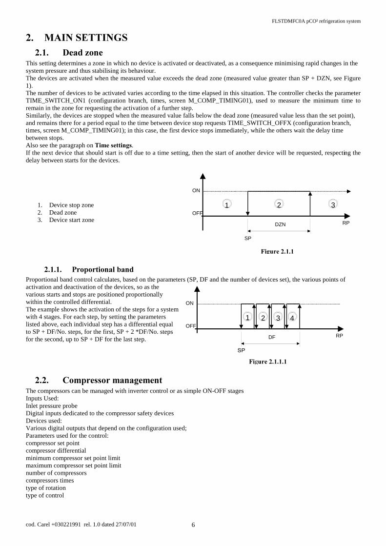
0$,16(77,1*6 'HDG]RQH
This setting determines a zone in which no device is activated or deactivated, as a consequence minimising rapid changes in the system pressure and thus stabilising its behaviour. The devices are activated when the measured value exceeds the dead zone (measured value greater than SP + DZN, see Figure 1). The number of devices to be activated varies according to the time elapsed in this situation. The controller checks the parameter TIME_SWITCH_ON1 (configuration branch, times, screen M_COMP_TIMING01), used to measure the minimum time to remain in the zone for requesting the activation of a further step. Similarly, the devices are stopped when the measured value falls below the dead zone (measured value less than the set point), and remains there for a period equal to the time between device stop requests TIME_SWITCH_OFFX (configuration branch, times, screen M_COMP_TIMING01); in this case, the first device stops immediately, while the others wait the delay time between stops. Also see the paragraph on 7LPHVHWWLQJV. If the next device that should start is off due to a time setting, then the start of another device will be requested, respecting the delay between starts for the devices.
1. Device stop zone 2. Dead zone 3. Device start zone
3URSRUWLRQDOEDQGProportional band control calculates, based on the parameters (SP, DF and the number of devices set), the various points of activation and deactivation of the devices, so as the various starts and stops are positioned proportionally within the controlled differential. The example shows the activation of the steps for a system with 4 stages. For each step, by setting the parameters listed above, each individual step has a differential equal to SP + DF/No. steps, for the first, SP + 2 *DF/No. steps for the second, up to SP + DF for the last step.
&RPSUHVVRUPDQDJHPHQWThe compressors can be managed with inverter control or as simple ON-OFF stages Inputs Used: Inlet pressure probe Digital inputs dedicated to the compressor safety devices Devices used: Various digital outputs that depend on the configuration used; Parameters used for the control: compressor set point compressor differential minimum compressor set point limit maximum compressor set point limit number of compressors compressors times type of rotation type of control
SP
RP DZN
ON
OFF 1 2 3
)LJXUH
RP DF
ON
OFF 4 3 2 1
)LgXUH

FLSTDMFC0A pCO² refrigeration system
cod. Carel +030221991 rel. 1.0 dated 27/07/01 7
212))FRPSUHVVRUPDQDJHPHQWZLWKRXWLQYHUWHUCan be configured with or without capacity-control 3DUDPHWHUVXVHGIRU212))FRQWUROnumber of capacity-control steps capacity-control step times compressor times 'HVFULSWLRQRIGHDG]RQHRUSURSRUWLRQDOEDQGRSHUDWLRQThe compressors are managed by the unit based on Set Point and a differential, which can be set on the screen (M_SETPOINT10, SET branch) and on the value read by the inlet probe. In the default configuration, dead zone control is activated - which can be set on the screen (M_MANUF220, manufacturer branch) - with FIFO rotation (M_MANUF220, manufacturer branch), respecting the various time settings (see the corresponding paragraph). For a description of dead zone or proportional band operation, please see the following paragraph.
&RPSUHVVRUPDQDJHPHQWZLWKLQYHUWHUIf the control is configured with an inverter, no capacity-control can be used 3DUDPHWHUVXVHGIRULQYHUWHUFRQWUROenable inverter inverter set point inverter step minimum compressor inverter opening 2SHUDWLQJGHVFULSWLRQThe compressor inverter can be activated on the screen (M_MANUF115 manufacturer branch), if no capacity-control steps are configured. A lower limit can be set for the inverter (M_MANUF240 manufacturer branch), The inverter is managed as follows: FDVHGHDG]RQHFRQWUROThe inverter is set on the first compressor, which will always be the first on and the last off. The control requires the setting of a differential (DZNI) for the control of the inverter (M_SETPOINT35 branch SET) from the inverter Set Point (SP) and the amount to increase the value by each second. The output of the inverter of compressor no. 1 starts increasing when the reading of probe a1 exceeds the inverter Set Point + the differential. A decrease occurs when the reading of probe a1 is below the value of the Set Point. In the zones between the SP and SP + DZNI, the output of the inverter is not changed. The output of the inverter is increased/decreased every second, by the value defined as the inverter step (M_SETPOINT35, SET branch) Caution:when the compressor inverter is enabled and is controlled outside of the dead zone, the compressors are started in the following way: - compressor 1, which is managed by the inverter, is
activated as soon as there is a start request; - if the request remains, the output of compressor 1 inverter
is increased; - if the request is still present, and the output of the inverter
reaches 10 Volts, the other compressors are requested, one at a time, with rotation (if selected) and respecting the time settings.
For deactivation , the following occurs: - the output of the inverter is decreased; - when the output of the inverter reaches 0 Volt, the other
compressors stop, one at a time, respecting the time settings and rotation;
- the last compressor to stop is no. 1. FDVHSURSRUWLRQDOEDQGFRQWUROThe control requires the setting of a set point and a differential (M_SETPOINT20-50, SET branch). When the value measured by the inlet probe is less than or equal to the value of the inverter set point, the output of the inverter is 0 Volt. As the value measured by probe B1 moves away from the set point, the analogue output is increased in proportion to the deviation, until reaching 10 Volts, when the value measured is greater than or equal to the inverter set point + differential.
SP
RPDZNI
0 V
10 V
2
)LJXUH
SP
0 V
10 V
RP
V
BLI
21 3
)LJXUH
FLSTDMFC0A pCO² refrigeration system
cod. Carel +030221991 rel. 1.0 dated 27/07/01 8
&RPSUHVVRUSDUDPHWHUV1XPEHURIFDSDFLW\FRQWUROVWHSV
Manufacturer branch, configuration, screen M_CONF_DEV02 One, two or three capacity control steps can be selected. This parameter is displayed only if there is at least one free output per configured compressor, and if the “Compressor Inverter” functions have not been enabled at the same time.
&DSDFLW\FRQWUROVWHSORJLFManufacturer branch, general parameters, screen M_CONF_UNLOADER If capacity-control steps are used, this parameter selects the operating logic for the outputs dedicated to the capacity-control steps (normally energised or normally de-energised).
&RPSUHVVRUVWDUWPRGHZLWKFDSDFLW\FRQWUROVWHSV
Manufacturer branch, general parameters, screen M_CONF_UNIT04 If the parameter is set to &SS&SS&SS the software gives the precedence to the complete start of each compressor; while if set to &&&SSSSSSthe software will first switch on all the compressors and then act on the capacity-control steps
&RPSUHVVRUVWRSPRGHZLWKFDSDFLW\FRQWUROVWHSV
Manufacturer branch, general parameters, screen M_CONF_UNIT04 If set to SSSSSS&&&, when the compressors are being stopped, first all the capacity-control steps are deactivated and then the corresponding compressors are stopped. This procedure is useful when wanting to limit the number of compressor stops and starts, and consequently extend the compressor working life. If SS&SS&SS& is set, when the compressors are being stopped, priority goes to the complete stop of the individual compressor. so as to more frequently alternate which compressors are on (obviously only with FIFO rotation).
&RPSUHVVRUDQGIDQURWDWLRQ
Manufacturer branch, general parameters, screen M_CONF_UNIT02 - M_CONF_UNIT06 Rotation can be DISABLED (number 1 is always turned on first, then 2 etc., while the highest number compressor always stops first), or FIFO rotation can be selected (the first on is the first off.)
&RPSUHVVRUDQGIDQFRQWURO
Manufacturer branch, general parameters, screen M_CONF_UNIT02 - M_CONF_UNIT06 Dead zone (see 'HDG]RQH) or proportional band control (see 3URSRUWLRQDOEDQG) can be selected.
7\SHRIFRPSUHVVRUFRQWUROManufacturer branch, general parameters, screen M_CONF_UNIT03 Can be proportional or proportional plus integral (only in proportional band):
• Proportional control Based on the set point entered (SET branch, screen M_SET_COMP), a proportional band is calculated, the width of which is equal to the differential set (SET branch, screen M_DIFF_DEVICE). The positions of the control stages of the devices are calculated within this band, according to the number of compressors configured and any capacity-control steps.
• Proportional and integral control Proportional plus integral control uses the same parameters as for just proportional, calculating the device activation steps according to the set point, differential, and the integration time set (Manufacturer branch, general parameters, screen M_CONF_UNIT03) The integral action is doubled if the conditions do not vary after the set time.
1XPEHURIFRPSUHVVRUVIRUFHGRQZLWKSUREHIDXOW
Manufacturer branch, general parameters, screen M_CONF_UNIT5 If the probe 1 failure or not connected alarm is activated (BROKEN_PROBE1), this parameter indicates the minimum number of compressors forced on.

FLSTDMFC0A pCO² refrigeration system
cod. Carel +030221991 rel. 1.0 dated 27/07/01 9
&RPSUHVVRUWLPHVHWWLQJVThe following is a list of all the time parameters used for compressor management.
7LPHEHWZHHQVWDUWUHTXHVWVGHDG]RQH
Manufacturer branch, general parameters, screen M_COMP_TIMING01 These parameters set the time between the successive start requests for the devices managed by the probes. Present only for dead zone control.
7LPHEHWZHHQVWRSUHTXHVWVGHDG]RQHManufacturer branch, general parameters, screen M_COMP_TIMING01 These parameters set the time between the successive stop requests for the devices managed by probes 1 and 2. Present only for dead zone control.
0LQLPXPFRPSUHVVRU21WLPH
Manufacturer branch, general parameters, screen M_COMP_TIMING02 Sets the minimum time (in seconds) the compressors stay on, that is, once activated, must remain on for the time set by this parameter.
0LQLPXPFRPSUHVVRU2))WLPH
Manufacturer branch, general parameters, screen M_COMP_TIMING02 Sets the minimum time the compressors stay off. The devices are not started again if the minimum time selected has not elapsed since the last stop.
0LQLPXPWLPHEHWZHHQVWDUWVRIGLIIHUHQWFRPSUHVVRUVManufacturer branch, general parameters, screen M_COMP_TIMING03 Represents the minimum time that must elapse between the start of one device and the next. This parameter allows simultaneous starts to be avoided
0LQLPXPWLPHEHWZHHQVWDUWVRIWKHVDPHFRPSUHVVRU
Manufacturer branch, general parameters, screen M_COMP_TIMING04 Sets the minimum time that must elapse between two starts of the same device, irrespective of the measured value and the set point. This parameter limits the number of starts per hour. If, for example, the maximum allowable number of starts per hour is 10, to guarantee this limit simply set a value of 360 seconds.
0LQLPXPWLPHEHWZHHQFDSDFLW\FRQWUROVWHSDFWLYDWLRQIRUWKHVDPHFRPSUHVVRU
Manufacturer branch, general parameters, screen M_TIME_UNLOAD Sets the minimum time that must elapse between the activation of two capacity-control steps or between the start of the compressor and its capacity control steps. The parameter is present only if capacity-control steps have been selected (M_MANUF325 manufacturer branch). This is a safety parameter if rotation with dead zone operation has been selected, as in fact the minimum time between requests also includes the time between the activation of two capacity-control steps or alternatively between the start of the compressor and its capacity-control steps.
)DQPDQDJHPHQWThe fans can be managed with inverter control or as simple ON-OFF stages
,QSXWV8VHGOutlet pressure probe Digital inputs dedicated to the fan safety devices
'HYLFHVXVHGVarious digital outputs that depend on the configuration used
3DUDPHWHUVXVHGIRUWKHFRQWUROFan set point Fan differential Minimum fan set point limit Maximum fan set point number of fans fan times type of rotation type of control
0
1
t
OFF
T_OFF_CPT_ON_CP
ONCP
t
)LJXUH
FLSTDMFC0A pCO² refrigeration system
cod. Carel +030221991 rel. 1.0 dated 27/07/01 10
212))IDQPDQDJHPHQWZLWKRXWLQYHUWHUThe fans are managed by the unit based on Set Point and a differential, which can be set on the screen (M_SETPOINT15, SET branch) and on the value read by the outlet probe. In the default configuration, SURSRUWLRQDOEDQG control is activated, which can be set on the screen (M_MANUF250, manufacturer branch) with FIFO rotation (M_MANUF250, manufacturer branch), respecting the various time settings. If a fan remains off due to an alarm, the pressure tends to increase, requesting the start of another fan; once the alarm has passed, the fan will restart normal operation.
)DQPDQDJHPHQWZLWKLQYHUWHU3DUDPHWHUVXVHG
Fan inverter set point Fan inverter differential
The fan inverter can be set on the screen (M_MANUF115, manufacturer branch). A minimum value can be set for the inverter (M_MANUF240, manufacturer branch, general parameters) The management of the inverter depends on the type of control performed: FDVHGHDG]RQHFRQWUROThe control requires a deviation to be set (M_SETPOINT40 branch SET) from the Set Point and the amount to increase the value by each second. Operation in this case is similar to the compressor inverter. FDVHSURSRUWLRQDOEDQGFRQWURO When the value measured by probe 2 is lower than the value of the inverter Set Point (M_SETPOINT25, SET branch), the output of the inverter is 0 Volt. As the value measured by probe 2 moves away from the inverter set point, the analogue output is increased in proportion to the deviation, until reaching 10 Volts, when the value measured is greater than or equal to the inverter set point + inverter differential.
)DQSDUDPHWHUV)DQURWDWLRQ
Manufacturer branch, general parameters, screen M_CONF_UNIT06 Rotation can be DISABLED (number 1 is always turned on first, then 2 etc., while the highest number fan always stops first), or FIFO rotation can be selected (the first on is the first off.)
)DQFRQWUROManufacturer branch, general parameters, screen M_CONF_UNIT06 Dead zone (see 'HDG]RQH) or proportional band control (see 3URSRUWLRQDOEDQG) can be selected.
1XPEHURIIDQVIRUFHGRQZLWKSUREHIDXOW
Manufacturer branch, general parameters, screen M_CONF_UNIT7 If the probe 2 failure or not connected alarm is activated (BROKEN_PROBE2), this parameter indicates the minimum number of fans forced on.
)DQWLPHVHWWLQJV7LPHEHWZHHQVWDUWUHTXHVWVGHDG]RQH
Manufacturer branch, general parameters, screen M_TIME_FAN_1 These parameters set the time between the successive start requests for the devices managed by the probes. Present only for dead zone control.
7LPHEHWZHHQVWRSUHTXHVWVGHDG]RQH
Manufacturer branch, general parameters, screen M_TIME_FAN_1 These parameters set the time between the successive stop requests for the devices managed by the probes. Present only for dead zone control.
0LQLPXPWLPHEHWZHHQVWDUWVRIGLIIHUHQWIDQV
Manufacturer branch, general parameters, screen M_TIME_FAN_2 Represents the minimum time that must elapse between the start of one device and the next. This parameter allows simultaneous starts to be avoided.
FLSTDMFC0A pCO² refrigeration system
cod. Carel +030221991 rel. 1.0 dated 27/07/01 11
6SHFLDOIXQFWLRQV
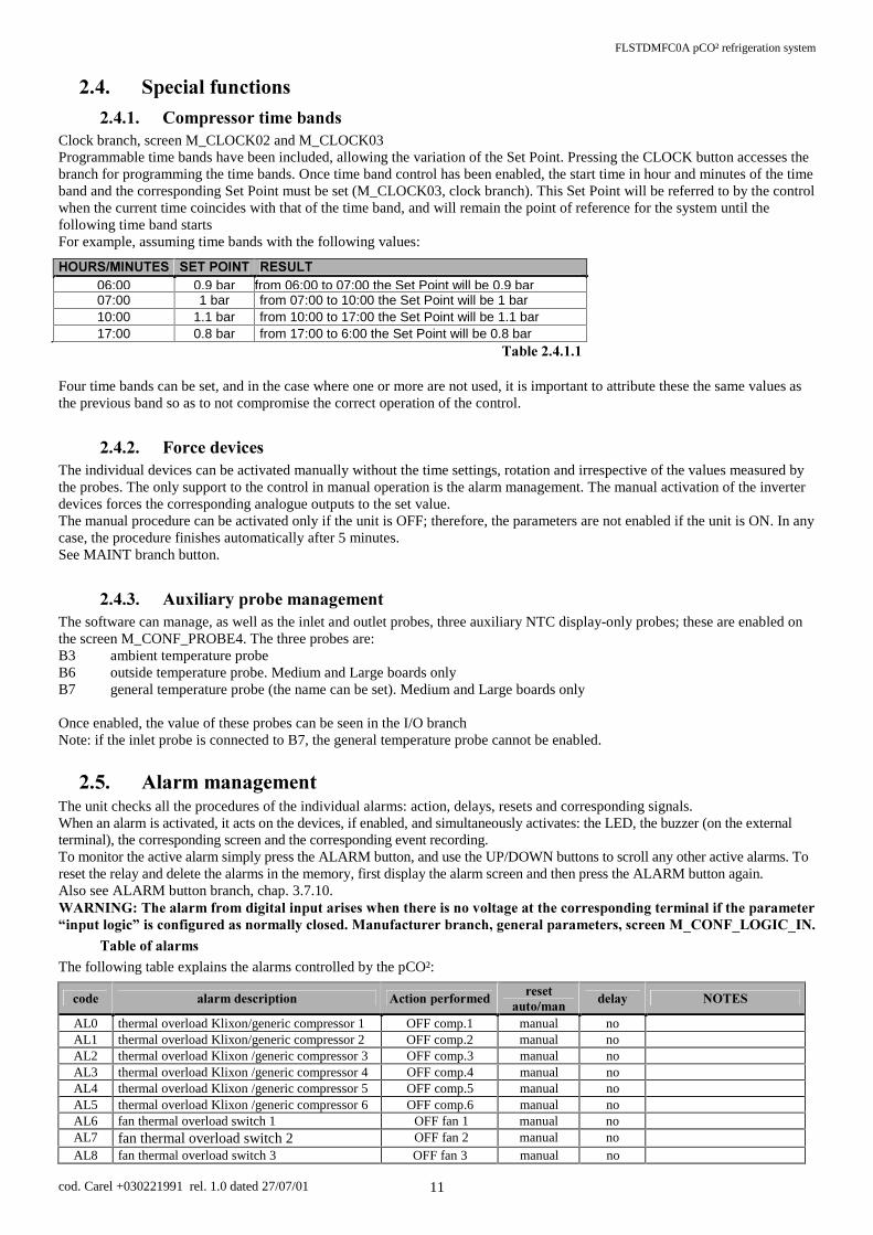
&RPSUHVVRUWLPHEDQGVClock branch, screen M_CLOCK02 and M_CLOCK03 Programmable time bands have been included, allowing the variation of the Set Point. Pressing the CLOCK button accesses the branch for programming the time bands. Once time band control has been enabled, the start time in hour and minutes of the time band and the corresponding Set Point must be set (M_CLOCK03, clock branch). This Set Point will be referred to by the control when the current time coincides with that of the time band, and will remain the point of reference for the system until the following time band starts For example, assuming time bands with the following values:
+28560,187(6 6(732,17 5(68/7 06:00 0.9 bar from 06:00 to 07:00 the Set Point will be 0.9 bar07:00 1 bar from 07:00 to 10:00 the Set Point will be 1 bar 10:00 1.1 bar from 10:00 to 17:00 the Set Point will be 1.1 bar 17:00 0.8 bar from 17:00 to 6:00 the Set Point will be 0.8 bar
7DEOH Four time bands can be set, and in the case where one or more are not used, it is important to attribute these the same values as the previous band so as to not compromise the correct operation of the control.
)RUFHGHYLFHVThe individual devices can be activated manually without the time settings, rotation and irrespective of the values measured by the probes. The only support to the control in manual operation is the alarm management. The manual activation of the inverter devices forces the corresponding analogue outputs to the set value. The manual procedure can be activated only if the unit is OFF; therefore, the parameters are not enabled if the unit is ON. In any case, the procedure finishes automatically after 5 minutes. See MAINT branch button.
$X[LOLDU\SUREHPDQDJHPHQWThe software can manage, as well as the inlet and outlet probes, three auxiliary NTC display-only probes; these are enabled on the screen M_CONF_PROBE4. The three probes are: B3 ambient temperature probe B6 outside temperature probe. Medium and Large boards only B7 general temperature probe (the name can be set). Medium and Large boards only Once enabled, the value of these probes can be seen in the I/O branch Note: if the inlet probe is connected to B7, the general temperature probe cannot be enabled.
$ODUPPDQDJHPHQWThe unit checks all the procedures of the individual alarms: action, delays, resets and corresponding signals. When an alarm is activated, it acts on the devices, if enabled, and simultaneously activates: the LED, the buzzer (on the external terminal), the corresponding screen and the corresponding event recording. To monitor the active alarm simply press the ALARM button, and use the UP/DOWN buttons to scroll any other active alarms. To reset the relay and delete the alarms in the memory, first display the alarm screen and then press the ALARM button again. Also see ALARM button branch, chap. 3.7.10. :$51,1*7KHDODUPIURPGLJLWDOLQSXWDULVHVZKHQWKHUHLVQRYROWDJHDWWKHFRUUHVSRQGLQJWHUPLQDOLIWKHSDUDPHWHU³LQSXWORJLF´LVFRQILJXUHGDVQRUPDOO\FORVHG0DQXIDFWXUHUEUDQFKJHQHUDOSDUDPHWHUVVFUHHQ0B&21)B/2*,&B,1
7DEOHRIDODUPV
The following table explains the alarms controlled by the pCO²:
FRGH DODUPGHVFULSWLRQ $FWLRQSHUIRUPHGUHVHW
DXWRPDQGHOD\ 127(6
AL0 thermal overload Klixon/generic compressor 1 OFF comp.1 manual no AL1 thermal overload Klixon/generic compressor 2 OFF comp.2 manual no AL2 thermal overload Klixon /generic compressor 3 OFF comp.3 manual no AL3 thermal overload Klixon /generic compressor 4 OFF comp.4 manual no AL4 thermal overload Klixon /generic compressor 5 OFF comp.5 manual no AL5 thermal overload Klixon /generic compressor 6 OFF comp.6 manual no AL6 fan thermal overload switch 1 OFF fan 1 manual no AL7 fan thermal overload switch 2 OFF fan 2 manual no AL8 fan thermal overload switch 3 OFF fan 3 manual no

FLSTDMFC0A pCO² refrigeration system
cod. Carel +030221991 rel. 1.0 dated 27/07/01 12
AL9 fan thermal overload switch 4 OFF fan 4 manual no AL9 fan thermal overload switch 5 OFF fan 5 manual no
AL10 pressure switch comp.1 OFF comp.1 manual no AL11 high/low pressure switch comp.2 OFF comp.2 manual no AL12 high/low pressure switch comp.3 OFF comp.3 manual no AL13 high/low pressure switch comp.4 OFF comp.4 manual no AL14 high/low pressure switch comp.5 OFF comp.5 manual no AL15 high/low pressure switch comp.6 OFF comp.6 manual no AL16 oil differential comp.1 OFF comp.1 manual can be set AL17 oil differential comp.2 OFF comp.2 manual can be set AL18 oil differential comp.3 OFF comp.3 manual can be set AL19 oil differential comp.4 OFF comp.4 manual can be set AL20 oil differential comp.5 OFF comp.5 manual can be set AL21 oil differential comp.6 OFF comp.6 manual can be set AL22 low liquid level alarm / manual can be set display only AL23 gen. low pressure switch compressors OFF automatic no AL24 gen. high pressure switch compressors OFF manual no AL25 maintenance comp. 1 / manual no display only AL26 maintenance comp. 2 / manual no display only AL27 maintenance comp. 3 / manual no display only AL28 maintenance comp. 4 / manual no display only AL29 maintenance comp. 5 / manual no display only AL30 maintenance comp. 6 / manual no display only AL31 pre-alarm low outlet pressure all fans OFF automatic no AL32 pre-alarm high outlet pressure all fans ON automatic can be set AL33 pre-alarm low inlet pressure all comps. OFF automatic can be set AL34 pre-alarm high inlet pressure all comps. ON automatic can be set AL35 Exceeded max no. inputs avail. / automatic no display only AL36 Exceeded max no. devices / automatic no display only AL37 Clock fault or battery discharged Disable time bands manual no AL38 probe 1 fault or disconnected no. of comps. ON
can be set manual no
AL39 probe 2 fault or disconnected no. of fans ON can be set
manual no
7DEOH
$ODUPVZLWKDXWRPDWLFUHVHWWhen one or more automatic reset alarms are detected, these are signalled by:
• red LED below the ALARM button on; • buzzer active (with external terminal) ; • the alarm relay changes status (the logic can be set in the manufacturer branch, general parameters, screen
M_CONF_LOGIC_AL), if enabled (manufacturer branch, unit configuration screen M_CONF_DEV04). Pressing the ALARM button silences the buzzer and displays the alarm codes. If the cause of the alarms is resolved, the devices that have shut-down will restart normal operation, and the status of the signal devices changes as follows:
• the alarm relay changes status; • the buzzer, if not silenced by pressing the ALARM button, stops; • the red LED below the ALARM button flashes.
If, in this situation, new alarms are activated, the initial situation will return. The UHG/('IODVKLQJ informs the user that there have been active alarms during the day and that the causes have now passed. To display the codes of the alarms that were activated, simply go to the alarm log (press the MENU or PROG button for the Built-In terminal, alarm log branch).
$ODUPVZLWKPDQXDOUHVHW
When one or more manual reset alarms are detected, these are signalled by: • red LED below the ALARM button on; • buzzer active (with external terminal) ; • the alarm relay changes status.
Pressing the ALARM button silences the buzzer and displays the screens of the activated alarms. If the cause of the alarms is resolved, the red LED stays on to inform the user that alarms have been activated during the day, and to press the ALARM button to reset this situation. In this situation, the alarm relay remains in an alarm condition. If, in this situation, new alarms are activated, the initial situation will return.
FLSTDMFC0A pCO² refrigeration system
cod. Carel +030221991 rel. 1.0 dated 27/07/01 13
7KHGHYLFHVUHPDLQRIIXQWLOWKHXVHUGHOHWHVWKHDODUPPHVVDJHV. The messages are deleted by pressing the ALARM button when the alarm messages are displayed. If the causes no longer exist, the status of the signal devices changes as follows:
• the alarm relay changes status (switches according to the set logic); • the buzzer, if not silenced by pressing the ALARM button, stops; • the red LED below the ALARM button goes off.
If, on the other hand, the cause of the alarms is still present, the initial situation will return.
$ODUPUHOD\
The user may decide whether to configure the alarm relay simply by enabling it (manufacturer branch, unit configuration, screen M_CONF_DEV04) and entering the relay to assign to the alarm (manufacturer branch, unit configuration, screen M_CONF_OUT_9). If enabled, a delay time can be set (screen M_PROG05, PROG branch) between the activation of an alarm and the change in the status of the signal relay. If the time is set to 0, the activation of the alarm relay is immediate.
$ODUPORJ
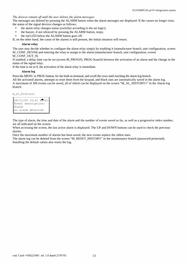
Press the MENU or PROG button, for the built-in terminal, and scroll the rows until reaching the alarm log branch. All the activated alarms, attempts to reset them from the keypad, and black outs are automatically saved in the alarm log. A maximum of 300 events can be saved, all of which can be displayed on the screen “M_AL_HISTORY1” in the Alarm log branch. m_al_history1
1 (YHQWGHVFULSWLRQ $ODUP QRDODUPGHWHFWHG
The type of alarm, the time and date of the alarm and the number of events saved so far, as well as a progressive index number, are all indicated on the screen. When accessing the screen, the last active alarm is displayed. The UP and DOWN buttons can be used to check the previous alarms. Once the maximum number of alarms has been saved, the new events replace the oldest ones. The alarm log can be deleted from the screen “M_RESET_HISTORY” in the maintenance branch (password-protected). Installing the default values also resets the log.

FLSTDMFC0A pCO² refrigeration system
cod. Carel +030221991 rel. 1.0 dated 27/07/01 14
86(5,17(5)$&(The user interface for this application is divided into four fundamental parts:
• D86(5VHFWLRQ, not password-protected, for monitoring the controlled values, setting the main control Set point, control differential, and displaying the active alarms and saved alarms;
• D 86(5 VHFWLRQ, password-protected, which sets all the control parameters for the various functions and processes managed by the program: Set point limits, alarm thresholds etc.; only the parameters regarding the manufacturer password-enabled functions are displayed and can be set;
• D6(59,&( VHFWLRQ, password-protected, reserved for service operations, that is, the management of the device hour counters, the calibration of the connected probes, and the forcing of the relay outputs;
• D0$18)$&785(5VHFWLRQ, password-protected, for configuring the system, selecting and activating the functions of the controlled devices. Thepassword-protectedManufacturer section contains a menu with four choices:
- Unit configuration - General parameters - Time settings - Unit initialisation
'LVSOD\The display used is an LCD, with 4 rows x 20 columns. The values and operating information are presented in the form of successive screens. The user can move around the screens using the buttons on the terminal, described as follows:
[5RZ +RPH5RZ 5RZ 5RZ
If the cursor is positioned in the top left corner (Home) pressing the UP/DOWN buttons accesses the successive screens in the selected branch. If the screen includes fields to be set, then pressing the ENTER button moves the cursor to these fields. Inside the setting fields, the values can be modified, within the limits envisaged, by pressing the UP/DOWN buttons. Once the value required has been set, press the ENTER button to save it
/('VXQGHUWKHEXWWRQVThree LEDs are located under the rubber buttons, and indicate respectively: ON/OFF button green LED - indicates that the instrument is on and in operation. On the built-in terminal, the ENTER
button lights up. ALARM button red LED - indicates the presence of an alarm situation; when flashing, the alarm condition is no longer
present. ENTER button yellow LED - on the external terminal indicates that the instrument is correctly powered
green LED - on the built-in terminal, indicates that the instrument is on and in operation.
([WHUQDONH\SDGLayout of the buttons on the pCO external terminal:
0(18 0$,17 35,17 ,2 &/2&. 6(7 352*
9(56,21 +($7 &22/ 212)) $/$50 83 '2:1 (17(5
FLSTDMFC0A pCO² refrigeration system
cod. Carel +030221991 rel. 1.0 dated 27/07/01 15
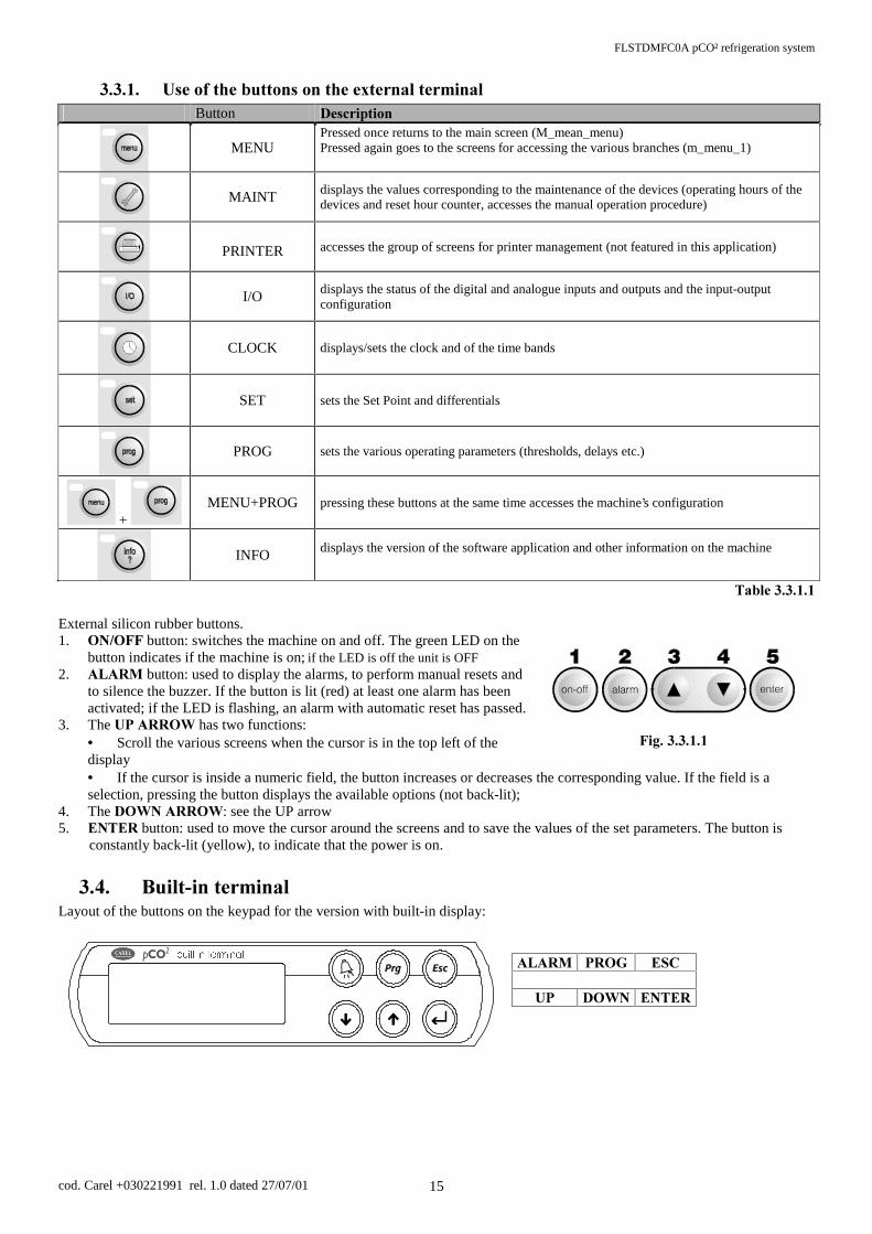
8VHRIWKHEXWWRQVRQWKHH[WHUQDOWHUPLQDO Button 'HVFULSWLRQ
MENU
Pressed once returns to the main screen (M_mean_menu) Pressed again goes to the screens for accessing the various branches (m_menu_1)
MAINT displays the values corresponding to the maintenance of the devices (operating hours of the
devices and reset hour counter, accesses the manual operation procedure)
PRINTER accesses the group of screens for printer management (not featured in this application)
I/O displays the status of the digital and analogue inputs and outputs and the input-output
configuration
CLOCK displays/sets the clock and of the time bands
SET sets the Set Point and differentials
PROG sets the various operating parameters (thresholds, delays etc.)
+ MENU+PROG pressing these buttons at the same time accesses the machine’s configuration
INFO displays the version of the software application and other information on the machine
7DEOH External silicon rubber buttons. 1. 212)) button: switches the machine on and off. The green LED on the
button indicates if the machine is on; if the LED is off the unit is OFF 2. $/$50 button: used to display the alarms, to perform manual resets and
to silence the buzzer. If the button is lit (red) at least one alarm has been activated; if the LED is flashing, an alarm with automatic reset has passed.
3. The 83$552:has two functions: • Scroll the various screens when the cursor is in the top left of the display • If the cursor is inside a numeric field, the button increases or decreases the corresponding value. If the field is a selection, pressing the button displays the available options (not back-lit);
4. The '2:1$552::see the UP arrow 5. (17(5 button: used to move the cursor around the screens and to save the values of the set parameters. The button is
constantly back-lit (yellow), to indicate that the power is on.
%XLOWLQWHUPLQDOLayout of the buttons on the keypad for the version with built-in display:
$/$50 352* (6&
83 '2:1 (17(5
)LJ
EXLOWLQWHUPLQDO
FLSTDMFC0A pCO² refrigeration system
cod. Carel +030221991 rel. 1.0 dated 27/07/01 16
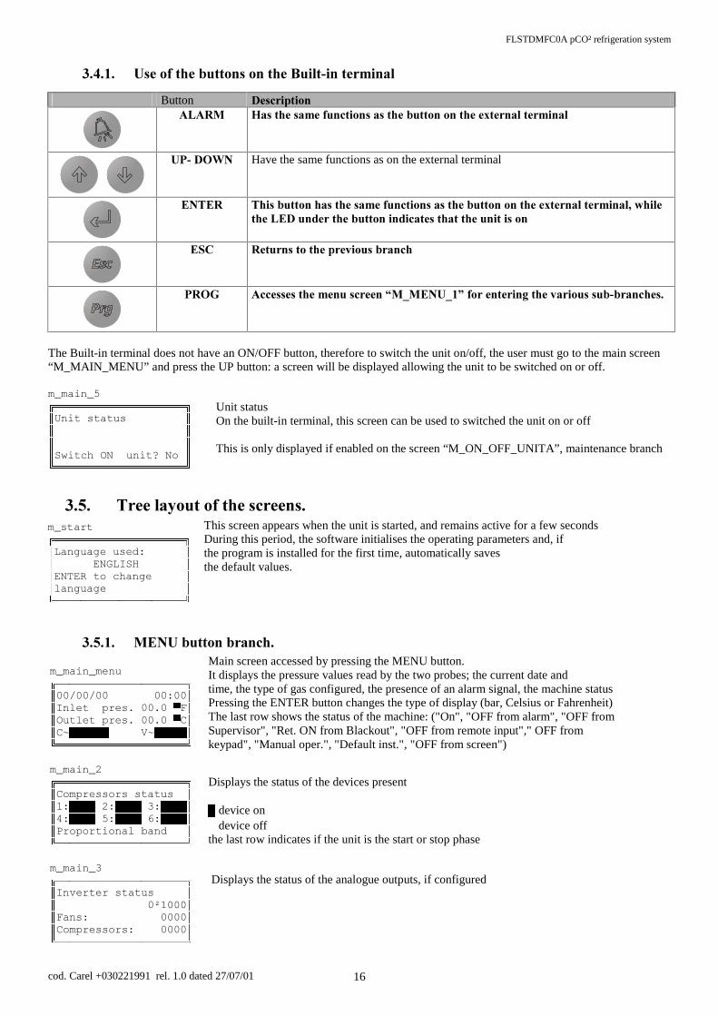
8VHRIWKHEXWWRQVRQWKH%XLOWLQWHUPLQDO
Button 'HVFULSWLRQ
$/$50 +DVWKHVDPHIXQFWLRQVDVWKHEXWWRQRQWKHH[WHUQDOWHUPLQDO
83'2:1 Have the same functions as on the external terminal
(17(5 7KLVEXWWRQKDVWKHVDPHIXQFWLRQVDVWKHEXWWRQRQWKHH[WHUQDOWHUPLQDOZKLOHWKH/('XQGHUWKHEXWWRQLQGLFDWHVWKDWWKHXQLWLVRQ
(6& 5HWXUQVWRWKHSUHYLRXVEUDQFK
352* $FFHVVHVWKHPHQXVFUHHQ³0B0(18B´ IRUHQWHULQJWKHYDULRXVVXEEUDQFKHV
The Built-in terminal does not have an ON/OFF button, therefore to switch the unit on/off, the user must go to the main screen “M_MAIN_MENU” and press the UP button: a screen will be displayed allowing the unit to be switched on or off.
Unit status On the built-in terminal, this screen can be used to switched the unit on or off This is only displayed if enabled on the screen “M_ON_OFF_UNITA”, maintenance branch
7UHHOD\RXWRIWKHVFUHHQVThis screen appears when the unit is started, and remains active for a few seconds During this period, the software initialises the operating parameters and, if the program is installed for the first time, automatically saves the default values.
0(18EXWWRQEUDQFKMain screen accessed by pressing the MENU button. It displays the pressure values read by the two probes; the current date and time, the type of gas configured, the presence of an alarm signal, the machine status Pressing the ENTER button changes the type of display (bar, Celsius or Fahrenheit) The last row shows the status of the machine: ("On", "OFF from alarm", "OFF from Supervisor", "Ret. ON from Blackout", "OFF from remote input"," OFF from keypad", "Manual oper.", "Default inst.", "OFF from screen") Displays the status of the devices present
device on device off
the last row indicates if the unit is the start or stop phase Displays the status of the analogue outputs, if configured
m_start
/DQJXDJHXVHG (1*/,6+ (17(5WRFKDQJH ODQJXDJH
m_main_menu
,QOHWSUHV ) 2XWOHWSUHV & &a 9a
m_main_2
&RPSUHVVRUVVWDWXV 3URSRUWLRQDOEDQG
m_main_3
,QYHUWHUVWDWXV ²1000 )DQV &RPSUHVVRUV
m_main_5
8QLWVWDWXV 6ZLWFK21XQLW"1R

FLSTDMFC0A pCO² refrigeration system
cod. Carel +030221991 rel. 1.0 dated 27/07/01 17
displays the status of the auxiliary probes, if enabled (only medium or large boards) ambient probe b3 outside temperature probe B6 general probe B7 (can be enabled only if the inlet probe is not connected to B7) Unit status. On the built-in terminal, this screen can be used to switch the unit on or off.
Pressing the MENU button (or PROG on the built-in terminal) from the main screen M_MAIN_MENU accesses the two screens M_MENU_1 and M_MENU_1; move around these screens with the UP and DOWN buttons, until reaching the branch that needs to be accessed, and then press the ENTER button to access the branch highlighted by the cursor.
Point branch input-output branch programming branch maintenance branch and manual procedures configuration branch time modification and print branch branch with information on the version of the software, the bios and the boot
0$,17EXWWRQPDLQWHQDQFHEUDQFKPressing the MAINT button accesses the following screens, which display the number of operating hours for each compressor and fan configured. The pCO² counts the operating time of each device, and every three hours saves this value in the flash memory on the board. If the number of operating hours of a device reaches or exceeds the set maintenance threshold, the corresponding alarm signal is activated.
Displays the operating hours of the various devices Displays the operating hours of the various devices Entering the password accesses the following screens The ON/OFF button can be enabled from the keypad If YES is selected the unit will remain off
m_main_4
$X[LOLDU\SUREH $PEWHPS& ([WWHPS & 00.0 &
m_main_5
8QLWVWDWXV 6ZLWFK21XQLW"1R
m_menu_1
6(732,17a ,1387287387a 6(RVICE LOOP: ~ 0$,17(1$1&(a
m_menu_2
&21),*85$7,21a &/2&.a ,1)250$7,216a $/$50+,6725<a
m_maint01
:RUNLQJ+RXUV &RPSUHVVRUK &RPSUHVVRUh &RPSUHVVRUK
m_maint03
:RUNLQJ+RXUV )DQK )DQK )DQ 000000h
m_maint05
0DLQWHQDQFHORRS ,QVHUWDVVLVWHQFH SDVVZRUG
m_on_off_unita
.H\ERUDG2Q2II HQDEOHG12 6ZLWFK-Off unit: NO

FLSTDMFC0A pCO² refrigeration system
cod. Carel +030221991 rel. 1.0 dated 27/07/01 18
Deletes all the alarms saved in the log Modifies the value of the maintenance threshold alarm for the compressors and fans, over which an alarm is activated as above Sets the operating hours of the compressors to zero Sets the operating hours of the fans to zero This screen is reserved for the parameters corresponding to the last maintenance operations performed on the system. This includes the date, the type of gas used, and the type of system. All this data can be displayed by pressing the INFO button Setting these parameters sets all the hour counters for the compressors and fans to zero Sets the calibration values for the probes, to be added or subtracted
0DQXDOGHYLFHRSHUDWLRQ
The following screens include the parameters that allow the manual activation of the individual devices, without the time settings, rotation and irrespective of the values measured by the probes. The only support to the control in manual operation is the alarm management. The manual activation of the inverter devices forces the corresponding analogue outputs to the set value. The manual procedure can only be activated if the unit is OFF; therefore the parameters are not enabled if the unit is ON. The manual procedure is in any case automatically ended after 5 minutes. The status of the corresponding device is displayed to the right. manual_protocol12
'HYLFHVIRUFLQJ HQGVZLWKLQ PLQXWHV
m_reset_history
(UDVHDODUP KLVWRU\1
m_maint06
0DLQWHQDQFH$ODUP &RPSUHVVRUV ZRUNRI WKUHVKROG
m_maint07
0DLQWHQDQFH$ODUP &RPSUHVVRUV ZRUNRI WKUHVKROG
m_maint08
&RPSUHVVRUVWLPH FRXQWHUVUHVHW 111111
m_maint09
)Dns time counters UHVHW 11111
m_maint10
/DVWPDLQWHQDQFH GDWH )UHRQW\SH --- 8QLWW\SH07
m_maint11
3UREHVFDOLEUDWLRQ ,QOHWEDU 2XWOHWEDU
FLSTDMFC0A pCO² refrigeration system
cod. Carel +030221991 rel. 1.0 dated 27/07/01 19
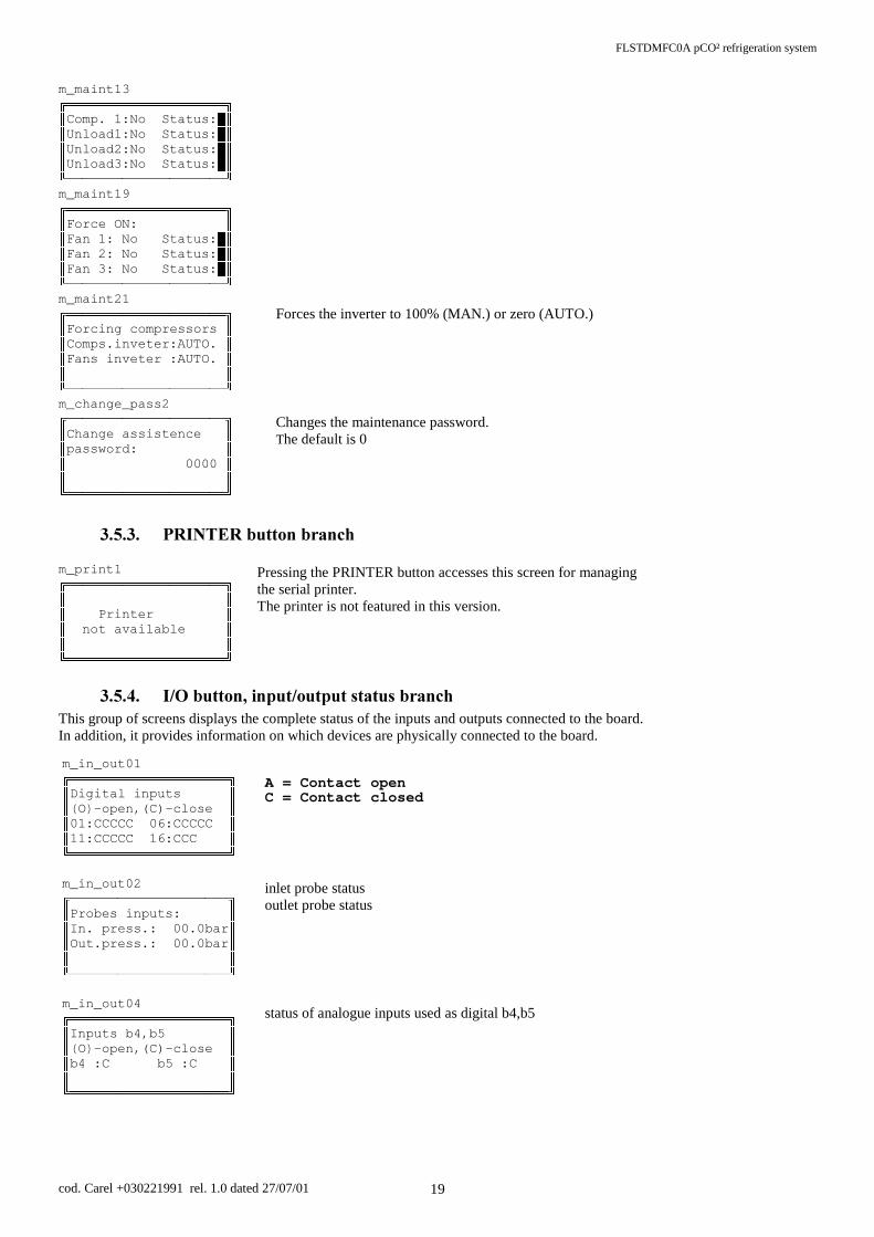
Forces the inverter to 100% (MAN.) or zero (AUTO.) Changes the maintenance password. The default is 0
35,17(5EXWWRQEUDQFK Pressing the PRINTER button accesses this screen for managing the serial printer. The printer is not featured in this version.
,2EXWWRQLQSXWRXWSXWVWDWXVEUDQFKThis group of screens displays the complete status of the inputs and outputs connected to the board. In addition, it provides information on which devices are physically connected to the board.
A = Contact open C = Contact closed inlet probe status outlet probe status status of analogue inputs used as digital b4,b5
m_in_out01
'LJLWDOLQSXWV 2-open,(C)-close &&&&&&&&&& &&&&&&&&
m_in_out02
3UREHVLQSXWV ,QSUHVVEDU 2XWSUHVVEDU
m_in_out04
,QSXWs b4,b5 2-open,(C)-close E&E&
m_maint13
&RPS1R6WDWXV 8QORDG1R6WDWXV 8QORDG2:No Status: 8QORDG1R6WDWXV
m_maint19
)RUFH21 )DQ1R6WDWXV )DQ1R6WDWXV )DQ1R6WDWXV
m_maint21
)RUFLQJFRPSUHVVRUV &RPSVLQYHWHU$872 )DQVLQYHWHU$872
m_change_pass2
&KDQJHDVVLVWHQFH SDVVZRUG 00
m_print1
3ULQWHU QRWDYDLODEOH

FLSTDMFC0A pCO² refrigeration system
cod. Carel +030221991 rel. 1.0 dated 27/07/01 20
status of analogue inputs used as digital b4,b5 (Large board only) Digital outputs status of analogue outputs (vary from 0÷1000)
The following screens show where the various devices configured are connected: Key: Inputs Outputs --- no device connected --- no device connected Therm.fan. fan thermal overload switch Comp.1 compressor Press.sw.A/B.C1 individual compressor high-low pressure switch Step1 C1 capacity-control Oil diff.C1 oil differential compressor Fan1 Fan Therm.comp.1 compressor thermal overload switch alarm Alarm relay Liquid level On/Off from input enable ON from digital input LP pressure switch general low pressure switch HP pressure switch general high pressure switch Table 3.5.4.1
type of board used
m_in_out05
,QSXWVEE 2-open,(C)-close E&E&
m_in_out20
'LJLWDORXWSXWV 2-Open,(C)-Close 2222222222 22222222
M_in_out25
,QYHUWHU²1000 <)DQV <--- 0000
m_see_in_out1
,QSXWRXWSXW FRQILJXUDWLRQ %RDUG --------------------
m_see_out1
2XWSXWVFRQILJ UHOay k1: UHOD\N UHOD\N
m_see_in_1
2XWSXWVFRQILJ UHOD\NIDQ UHOD\NIDQ UHOD\NIDQ
m_see_in_7
,QSXWVFRQILJ E E

FLSTDMFC0A pCO² refrigeration system
cod. Carel +030221991 rel. 1.0 dated 27/07/01 21
&ORFNEUDQFK Sets the date Enables the daily time bands 4 bands are available with the corresponding 4 set points that can be set within the limits configured in the PROG branch
6(7EXWWRQVHWSRLQWEUDQFKPressing the SET button accesses the following screen for displaying and setting the Set Point and differential values for the compressors and the fans.
Compressors Displays if the compressors are working with dead zone or proportional band control Displays the Set Point and the differential Compressors Changes the Set Point within the limits set on the screen M_LIMIT_SET PROG branch Changes the Set Point within the limits set on the screen M_LIMIT_SET_FAN, PROG branch This screen is only displayed if the compressor inverter is enabled indicates if the inverter is working with proportional band control Sets an inverter Set Point in proportional band Screen only displayed if the fan inverter is enabled and is working in proportional band. Indicates if the inverter is working in dead zone or proportional band Sets an inverter Set Point in proportional band
m_see_set_comp
&RPSUHVVRUV 3URSRUWLRQDO%DQG 6HWEDU & 'LIIEDU
m_set_comp
&RPSUHVVRUV 3URSRUWLRQDO%DQG &KDQJH 6HWSRLQWEDU
m_set_fan
)DQV 3URSRUWLRQDO%DQG &KDQJH 6HWEDU &
m_inv_comp_step
&RPSUHVVRUV,QYHWHU 3URSRUWLRQDOEDQG &KDQJH 6HWSRLQWEDU
m_set_inv_fan
)DQVLQYHUWHU 3URSRUWLRQDOEDQG &KDQJH 6HWSRLQWEDU
m_clock01
&KDQJHKRXUGDWH +RXU 'DWH 'G0P<HDU
m_clock02
'DLO\WLPH]RQHV ZLWKVHWSRLQW YDULDWLRQ HQDEOHG1
m_clock03
K6HW K6HW K6HW K6HW
FLSTDMFC0A pCO² refrigeration system
cod. Carel +030221991 rel. 1.0 dated 27/07/01 22
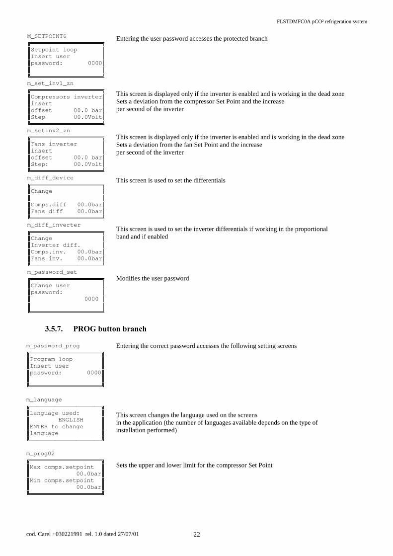
Entering the user password accesses the protected branch This screen is displayed only if the inverter is enabled and is working in the dead zone Sets a deviation from the compressor Set Point and the increase per second of the inverter This screen is displayed only if the inverter is enabled and is working in the dead zone Sets a deviation from the fan Set Point and the increase per second of the inverter This screen is used to set the differentials This screen is used to set the inverter differentials if working in the proportional band and if enabled Modifies the user password
352*EXWWRQEUDQFK
Entering the correct password accesses the following setting screens This screen changes the language used on the screens in the application (the number of languages available depends on the type of installation performed) Sets the upper and lower limit for the compressor Set Point
M_SETPOINT6
6HWSRLQWORRS ,QVHUWXVHU SDVVZRUG
m_set_inv1_zn
&RPSUHVVRUVLQYHUWHU LQVHUW RIIVHt 00.0 bar 6WHS9ROW
m_setinv2_zn
)DQVLQYHUWHU LQVHUW RIIVHWEDU 6WHS9ROW
m_diff_device
&KDQJH &RPSVGLIIEDU )DQVGLIIEDU
m_diff_inverter
&KDQJH ,QYHUWHUGLII &RPSVLQY0bar )DQVLQYEDU
m_password_set
&KDQJHXVHU SDVVZRUG
m_password_prog
3URJUDPORRS ,QVHUWXVHU SDVVZRUG
m_language
/DQJXDJHXVHG (1*/,6+ (17(5WRFKDQJH ODQJXDJH
m_prog02
0D[FRPSVVHWSRLQW EDU 0LQFRPSVVHWSRLQW EDU
FLSTDMFC0A pCO² refrigeration system
cod. Carel +030221991 rel. 1.0 dated 27/07/01 23
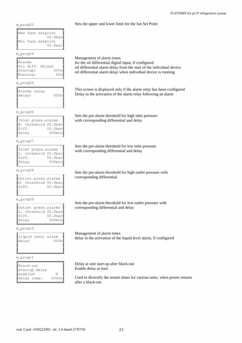
Sets the upper and lower limit for the fan Set Point Management of alarm times for the oil differential digital input, if configured oil differential alarm delay from the start of the individual device oil differential alarm delay when individual device is running This screen is displayed only if the alarm relay has been configured Delay in the activation of the alarm relay following an alarm Sets the pre-alarm threshold for high inlet pressure with corresponding differential and delay Sets the pre-alarm threshold for low inlet pressure with corresponding differential and delay Sets the pre-alarm threshold for high outlet pressure with corresponding differential Sets the pre-alarm threshold for low outlet pressure with corresponding differential and delay Management of alarm times delay in the activation of the liquid level alarm, if configured Delay at unit start-up after black-out Enable delay at start Used to diversify the restart times for various units, when power returns after a black-out
m_prog03
0D[IDQVVHWSRLQW EDU 0LQIDQVVHWSRLQW EDU
m_prog04
$ODUPV 2LOGLIIGHOD\V 6WDUWXSV 5XQQLQJV
m_prog05
$ODUPVUHOD\ GHOD\V
m_prog06
,QOHWSUHVVDODUPV +WKUHVKold 00.0bar 'LIIEDU 'HOD\PLQ
m_prog07
,QOHWSUHVVDODUPV /WKUHVKROGEDU 'iff. 00.0bar 'HOD\PLQ
m_prog08
2XWOHWSUHVVDODUPV +WKUHVKROGEDU 'LIIEDU
m_prog09
2XWOHWSUHVVDODUPV /WKUHVKROGEDU 'LIIEDU 'HOD\PLQ
m_prog10
/LTXLGOHYHODODUP GHOD\V
m_prog11
%ODFN-out VWDUWXSGHOD\ HQDEOHG1 'HODy time: 0000s

FLSTDMFC0A pCO² refrigeration system
cod. Carel +030221991 rel. 1.0 dated 27/07/01 24
Enable to unit shut-down due to: - supervisor - inlet or outlet probe broken Changes the user password
,1)2EXWWRQEUDQFKThis group of screens is accessed by pressing the INFO button. The screens provide information on the characteristics of the system, the software installed and the date of the most recent maintenance performed.
Code, date, version of the application Supply voltage to the pCO² board, the type of board used the version and the date of the Bios and Boot Screen displaying the last maintenance performed the type of refrigerant used and the type of system configured
0(18352*EXWWRQVXQLWFRQILJXUDWLRQEUDQFKThe screens in this branch can be accessed only by personnel who know the manufacturer password
Entering the correct password accesses the following setting screens (default 1234) This is a sub-menu that allows access to the various manufacturer branches
Unit configuration → enable devices and define their position on the board General parameters → general parameter settings Times → main time settings for the management of the compressors and fans Unit initial. → default installation, password management, supervisor management N.B. All the parameters in the manufacturer branch can only be modified with the machine off
m_info01
67$1'$5'&$5(/ &2'FLSTDMFC0A 9HUVLRQ -MAR-2000
m_info02
6XSSO\YROWDJH9 %RDUGW\SH60$// %LRV %RRW
m_info03
/DVWPDLQWHQDQFH GDWH )UHRQW\SH5 8QLWW\SH71
m_manuf01
0DQXIDFWXUHUORRS ,QVHUW SDVVZRUG
m_manuf_menu
81,7&21),*85$7,21a *(1(5$/3$5$0(7(5a 7,0INGS ~ ,1,7,$/,=$7,21a
m_prog12
6ZLFK2))XQLW PRGH 2))E\VXSHUYLVRU1 3UREHVIDXOW\1
m_change_pass3
&KDQJHXVHU SDVVZRUG

FLSTDMFC0A pCO² refrigeration system
cod. Carel +030221991 rel. 1.0 dated 27/07/01 25
8QLWFRQILJXUDWLRQ
Configures the number of inputs per compressor and the type: A: One generic input only (instant manual reset) B: 2 inputs: 1 for the thermal overload (instant manual reset) plus 1 for the oil differential (delayed with manual reset) C: 2 inputs: 1 for the thermal overload plus 1 for the high/low pressure switch (instant with settable reset) D: 3 inputs: 1 for overload, 1 for high/low pressure switch, and 1 for the oil differential Configures the number of fans, compressors and capacity-control steps per compressor: - number of fans - number of compressors - number of capacity-control steps (cannot be configured with the compressor inverter) The software automatically limits the number of devices that can be configured according to the inputs and outputs available for that type of board enables or disables the inverter on the first compressor (cannot be configured if capacity-control steps are present) enables or disables the fan inverter Enables the alarm relay. If not configured, an extra output is available Enable inputs: general low pressure switch (automatic reset) general high pressure switch (manual reset) Enable inputs enable unit on/off from digital input, priority over keypad command enable liquid level alarm from digital input (display only) Enable auxiliary probes, display only enable NTC ambient temperature probe enable NTC outside temperature probe (medium or large board only) enable general NTC temperature probe (medium or large board only)
In the following two screens, the type of inlet and outlet probe connected can be configured Type of analogue probes:
Õ Carel NTC temperature probes, (50 ÷ 100°C; R/T 10KΩ at 25°C), Õ Voltage: 0 ÷ 1Vdc or 0 ÷ 10Vdc Õ Current: 0 ÷ 20mA or 4 ÷ 20mA
defines the type of inlet probe connected defines the position of the inlet probe (B1 or B7); for Medium or Large boards only note: if positioned at b7, the NTC general temperature probe cannot be configured
m_conf_probe1
,QOHWSUREH W\SH 17& %RDUG,QZLULQJ%
m_conf_dev01
&RPSUHVVRULQSXWV W\SHVHOHFWLRQ& 2YHUORDGSUHVVRVWDW KLJKORZSUHVVXUH
m_conf_dev02
&RQILJXUDWLRQ )DQVQXPEHU &RPSVQXPEHU 8QORDGVQXPEHU
m_conf_dev03
&RPSUHVVRULQYHUWHU ',6$%/(' )DQVLQYHUWHU ',6$%/('
m_conf_dev04
$ODUPUHOD\ HQDEOHG1R
m_conf_dev05
(QDEOHLQSXWV *HQ/3SUHVVRVWDW1 *HQ+3SUHVVRVWDW1
m_conf_dev06
(QDEOHLQSXWV 2Q2))E\GLJLQ1 /LTXLGOLYHODO1
m_conf_probe4
3UREHVHQDEOH %$PELHQWWHPS1 %([WHUQDOWHPS1 %1

FLSTDMFC0A pCO² refrigeration system
cod. Carel +030221991 rel. 1.0 dated 27/07/01 26
defines the type of outlet probe connected defines the position of the outlet probe (B2 or B8); for Medium or Large boards only Sets the limits for the inlet probes Sets the limits for the outlet probes sets the type of freon used (used to convert from pressure to temperature) can be configured: none, R22, R134a, NH3, R404a
The position the various digital inputs for the compressors on the board can be configured. The software automatically limits the inputs that are already occupied The following inputs can be used: all the digital inputs analogue inputs B4,B5, used as digital analogue inputs B9,B10 (Large board only) used as digital To reverse the position of two inputs, proceed as follows:
1. Position the first device on input -- 2. Position the second device on the previous input of the first device 3. Position the first device on the previous input of the second device
Note: if a device remains configured at position --, it is not considered Position of the digital inputs used as safety devices for the compressors Position of the digital inputs used as safety devices for the fans Position on the board of the digital input used as an external ON-OFF this parameter is only displayed if enabled this parameter is only displayed if enabled Position on the board of the digital input used as general low pressure switch general high pressure switch these parameters are only displayed if enabled
m_conf_probe2
2XWOHWSUREH W\SH 17C %RDUG,QZLULQJ%
m_conf_probe3
,QSUHVVHQGVFDOH 0LQ0D[ 2XWpress. end scale 0LQ0D[
m_conf_freon
7\SHRIIUHRQ ---
m_conf_inout_1
%RDUGGLJLQZLULQJ FRPS2YHUO &RPSRLOGLII +3/3SUHVV&
m_conf_inout_2
%RDUGGLJLQZLULQJ FRPS2YHUO Comp2 oil diff.00 +3/3SUHVV&
m_dig_on_off1
%RDUGGLJLQZLULQJ 2Q2IIE\GLJLWDO Lnput 00
m_dig_on_off2
%RDUGGLJLQZLULQJ /LTXLGOLYHO DOarm 00
m_conf_main_pss
%RDUGGLJLQZLULQJ *HQ/3SUHVV *HQ.HP press.: 00

FLSTDMFC0A pCO² refrigeration system
cod. Carel +030221991 rel. 1.0 dated 27/07/01 27
In the following screens, the outputs on the board can be configured for the various devices To reverse the position of two outputs, proceed as follows:
1. Position the first device on output 00 2. Position the second device on the previous output of the first device 3. Position the first device on the previous output of the second device
Note: During normal operation, DO NOT leave any device configured in position 00 Position on the board of the digital outputs for the first compressor Position on the board of the digital outputs for the fans If outputs are available and if the alarm relay has been enabled, its position can be configured
*HQHUDOSDUDPHWHUV Logic of the digital inputs Normally open: when there is no alarm the contact is open Logic of the remote On/Off from digital input Normally open: unit Off from digital input The type of reset for the high/low pressure switch for each compressor can be set Automatic: when the alarm stops, the compressor starts this screen is only displayed if the high/low pressure switches are enabled for each compressor Logic of the alarm relay This screen is not visible unless the alarm relay is enabled Enable FIFO rotation (first on - first off) for the compressors Type of control used for compressor management: Proportional band or Dead zone
m_conf_out_1
FRPSUHOD\Q 8QORDGUHOD\Q 8QORDGUHOD\Q 8QORDGUHOD\Q
m_conf_out_7
%RDUGGRXWZLULQJ )DQUHOD\Q )DQUHOD\Q )DQUHOD\Q
m_conf_out_8
%RDUGGRXWZLULQg: $ODUPUHOD\Q
m_conf_logic_in
'LJLWDOLQSXWV /RJLF12 1RDODUP
m_logic_onoff
2Q2))E\GLJLQSXW /RJLF12 2))XQLW
m_type_res_hl_p
$ODUPSUHVVRVWDW +LJK/RZFRPS UHVHWW\SH $8720$7,&
m_manuf210
$ODUPUHOD\ ORJLF 1250$//<&/26(
m_conf_unit2
&RPSVURWDWLRQ ',6$%/(' &RPSVUHJXODWLRQ 3523257,21$/%$1'
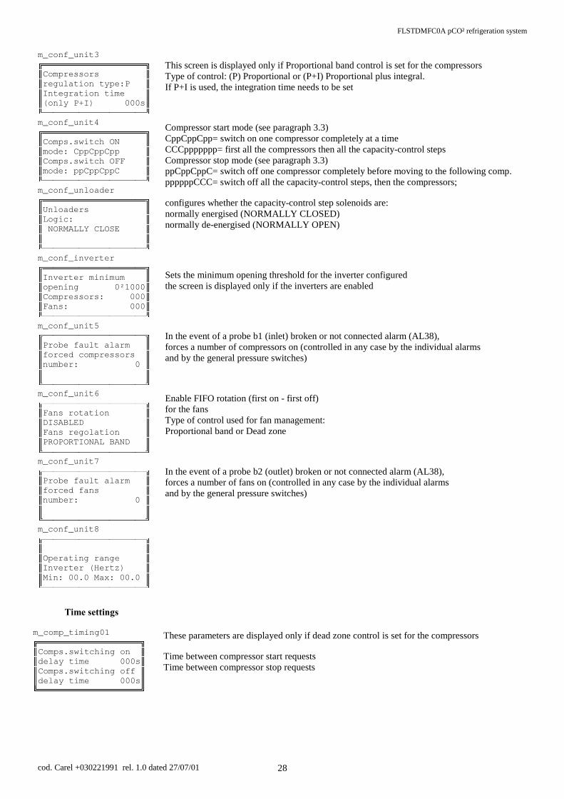
FLSTDMFC0A pCO² refrigeration system
cod. Carel +030221991 rel. 1.0 dated 27/07/01 28
This screen is displayed only if Proportional band control is set for the compressors Type of control: (P) Proportional or (P+I) Proportional plus integral. If P+I is used, the integration time needs to be set Compressor start mode (see paragraph 3.3) CppCppCpp= switch on one compressor completely at a time CCCppppppp= first all the compressors then all the capacity-control steps Compressor stop mode (see paragraph 3.3) ppCppCppC= switch off one compressor completely before moving to the following comp. ppppppCCC= switch off all the capacity-control steps, then the compressors; configures whether the capacity-control step solenoids are: normally energised (NORMALLY CLOSED) normally de-energised (NORMALLY OPEN) Sets the minimum opening threshold for the inverter configured the screen is displayed only if the inverters are enabled In the event of a probe b1 (inlet) broken or not connected alarm (AL38), forces a number of compressors on (controlled in any case by the individual alarms and by the general pressure switches) Enable FIFO rotation (first on - first off) for the fans Type of control used for fan management: Proportional band or Dead zone In the event of a probe b2 (outlet) broken or not connected alarm (AL38), forces a number of fans on (controlled in any case by the individual alarms and by the general pressure switches)
7LPHVHWWLQJV These parameters are displayed only if dead zone control is set for the compressors Time between compressor start requests Time between compressor stop requests
m_conf_unit3
&RPSUHVVRUV UHJXODWLRQW\SH3 ,QWHJUDWLRQWLPH RQO\3,V
m_conf_unit4
&RPSVVZLWFK21 PRGH&SS&SS&SS &RPSVVZLWFK2)) PRGHSS&SS&SS&
m_conf_unloader
Unloaders /RJLF 1250$//<&/26(
m_conf_inverter
,nverter minimum RSHQLQJ²1000 &RPSUHVVRUV )DQV
m_conf_unit5
3Uobe fault alarm IRUFHGFRPSUHVVRUV QXPEHU
m_conf_unit6
)DQs rotation ',6$%/(' )DQVUHJRODWLRQ 3523257,21$/%$1'
m_conf_unit7
3UREe fault alarm IRUFHGIDQV QXPEHU
m_conf_unit8
2SHUDWLQJUDQJH ,QYHUWHU+HUW] 0LQ0D[
m_comp_timing01
&RPSVVZLWFKLQJRQ GHOD\WLPHV &RPSVVZLWFKLQJRII GHOD\WLPHV

FLSTDMFC0A pCO² refrigeration system
cod. Carel +030221991 rel. 1.0 dated 27/07/01 29
Minimum ON time for same compressor Minimum OFF time for same compressor Also see paragraph 3.3.1 Minimum time between two start requests for different compressors avoids simultaneous starts Minimum time between two effective starts of same compressor This parameter is displayed only if the capacity-control steps are configured Delay between the request and the effective activation of the capacity-control steps Minimum time between two starts of the same fan Minimum time between two stops of the same fans Minimum time between two start requests for different fans Avoids simultaneous starti
,QLWLDOLVDWLRQ
Supervisor configuration Enters the identification number of the pCO² board for the supervisor serial network communication speed with the supervisor system type of conversion protocol changes the password for access to the various branches Deletes the entire permanent memory and resets the default values (N.B. This operation should be performed when the machine is off)
m_comp_timing02
0LQLPXPFompressors SRZHU-on time 0000s 0LQLPXPFRPSUHVVRUV SRZHU-off time 0000s
m_comp_timing03
&RPSUHVVRUs 0LQWLPHEHWZHHQ GLIIHUHQWVWDUW V
m_comp_timing04
&RPSUHVVRU 0LQWLPHEHWZHHQ VDPHVWDUWV
m_comp_timing05
8QORDGHUV 6ZLWFKLQJ2Q GHOD\WLPH V
m_time_fan_1
)DQVVZLWFKLQJ21 GHOD\WLPHV )DQVVZLWFKLQJ2)) GHOD\WLPHV
m_time_fan_2
)DQV 0LQWLPHEHWZHHQ GLIIHUHQWVWDUW V
m_conf_superv1
6XSHUYLVRUV\VWHP ,GHQWLILFDWLRQ1 &RP6SHHGEDXG 3URWRFROW\Se:CAREL
m_manuf420
&KDQJHSDVVZRUGV 0DQXIDFWXUHU $VVLVWHQFH 8VHU0
m_manuf425
'HIDXOWYDOXHV LQLWLDOL]DWLRQ1 - PLEASE WAIT -

FLSTDMFC0A pCO² refrigeration system
cod. Carel +030221991 rel. 1.0 dated 27/07/01 30
$/$50EXWWRQEUDQFKIf there are no active alarms or alarms in the memory
• the buzzer is off • alarm relay is in rest status • the red LED is off
pressing the ALARM button will display the following screen:
If there is at least one active alarm • the buzzer is on • the alarm relay has changed status • the red LED is on
pressing the ALARM button and the using the UP and DOWN buttons will display all of the alarms present in the memory. To reset or delete an alarm from the memory, press the ALARM button again (also see paragraph 3.3.2)
displays if the generic safety device from the digital input corresponding to that compressor has been activated stops the corresponding compressor manual reset displays if the thermal overload corresponding to that compressor has been activated stops the corresponding compressor manual reset displays if the thermal overload corresponding to that fan has been activated switches off the corresponding fan manual reset displays if the high/low pressure switch corresponding to that compressor has been activated stops the corresponding compressor automatic reset Displayed if the input configured as the oil differential changes status for a set time (screen M_ALARM1, PROG branch) stops the corresponding compressor manual reset Displayed if the input configured as the liquid level changes status for a set time (screen M_ALARM1. PROG branch) Display only manual reset
no_alarm
1RDODUP GHWHFWHG
al0
DO 2YHUORDG.OL[RQ &RPSUHVVRU
al0
DO 2YHUORDG.OL[RQ &RPSUHVVRU
al6
DO )DQ 2YHUORDG
al10
DO &RPSUHVVRU +LJKORZ3UHVVXUH SUHVVRVWDW
al16
DO 2LOGLIIHUHQWLDO SUHVVRVWDW RU'HPDQG&RROLQJ
al22
DO /LTXLGOHYHO $ODUP

FLSTDMFC0A pCO² refrigeration system
cod. Carel +030221991 rel. 1.0 dated 27/07/01 31
Displayed only if the general low pressure switch is activated. All compressors will be stopped. Alarm with automatic reset Displayed only if the general high pressure switch is activated. All compressors will be stopped. Alarm with manual reset Displayed only if the operating hours of compressor no. 1 exceed the limit Call service Display only Low outlet pressure pre-alarm Displayed if the low outlet pressure limit is exceeded Goes off after a pre-set time (see screen M_ALARM6, PROG branch) Stops all the fans Automatic reset High outlet pressure pre-alarm Displayed if the high outlet pressure limit is exceeded (screen M_ALARM5, PROG branch) Starts all the fans Automatic reset Low inlet pressure pre-alarm Displayed if the low inlet pressure limit is exceeded Goes off after a pre-set time (see screen M_ALARM4, PROG branch) Stops all the compressors Automatic reset High inlet pressure pre-alarm Displayed if the high inlet pressure limit is exceeded Goes off after a pre-set time (see screen M_ALARM3, PROG branch) Starts all the compressors Automatic reset indicates that there is an error in the configuration of the inputs on the board display only automatic reset call service indicates that there is an error in the configuration of the outputs on the board display only automatic reset call service
al23
DO *HQHUDOORZSUHVVXUH SUHVVRVWDW
al24
DO +LJKSUHVVXUH JHQHUDOSUHVVRWDW
al25
DO &RPSUHVVRU PDLQWHQDQFH
al31
DO 2XWOHW ORZSUHVVXUH
al32
DO 2XWOHW KLJK3UHVVXUH
al33
DO ,QOHW ORZ3UHVVXUH
al34
DO ,QOHW KLJKSUHVVXUH
al35
DO &RQILJXUDEOH GLJLWDOLQSXWVQXP H[FHHGHG
al36
&RQILJXUDEOH GHYLFHVQXPEHU H[FHHGHG

FLSTDMFC0A pCO² refrigeration system
cod. Carel +030221991 rel. 1.0 dated 27/07/01 32
Clock board fault or flat battery this alarm inhibits the time bands Warns that the values measured by the inlet probe are not possible Check the connection and the probe itself Inhibits compressor control Some compressors can be forced on when this alarm is activated Warns that the values measured by the outlet probe are not possible Check the connection and the probe itself Inhibits fan control Some fans can be forced on when this alarm is activated
212))EXWWRQEUDQFKThere are various ways to control the switching on/off of the unit (see paragraph Machine On/Off). One of the ways is using the On-Off button on the external keypad: • Unit off (OFF from keypad) pressing the ON/OFF button starts the machine (LED under ON-OFF button lights up). • Unit on, pressing the ON/OFF button turns the machine off, forcing the outputs to zero; the LED under the button goes off. When using the built-in terminal, go to the main screen and press the UP button. The following screen will appear:
This screen can be used to switch the unit on or off (also see the paragraph Machine On/Off)
/RJEUDQFKTo access this branch, go to the main screen, press the Menu button and then scroll the rows until the “ALARM LOG →” row is selected, then press the ENTER button; the following screen will appear:
The first screen displayed is the most recent alarm activated. Pressing the UP button scrolls
the log in reverse order of time. All the alarms are saved together with the date. The data from when the unit was restarted and when the user attempted to reset the alarms by pressing the ALARM button can also be saved.
clock
DO &ORFNERDUGEURNHQ RUGLVFKDUJHG EDWWery
broke_probe1
DO $ODUP 3UREHLQOHWIDXOW RUQRWFRQQHFWHG
broke_probe2
DO $ODUP 3UREHRXWOHWIDXOW RUQRWFRQQHFWHG
m_main_5
8QLWVWDWXV 2))NH\ERDUG 6ZLWFK21XQLW"1R
m_al_history1
1 (YHQWGHVFULSWLRQ $ODUP QRDODUPGHWHFWHG

FLSTDMFC0A pCO² refrigeration system
cod. Carel +030221991 rel. 1.0 dated 27/07/01 33
3&2,167580(17$1'$&&(6625<&2'(6 7HUPLQDOIRUIOXVKSODVWLFER[IRUEXLOWLQPRXQWLQJCode Description PCOI00PGL0 Large backlit graphic display PCOI000CBB LCD backlit display, 4x20 PCOI000CB0 LCD display, 4x20 7HUPLQDOIRUSODVWLFER[IRUEXLOWLQZDOOPRXQWLQJCode Description PCOT00PGH0 Small backlit graphic display, 64x128 pixels PCOT000CB0 LCD display 4x20 PCOT00SCB0 LCD display 4x20, for connection to serial printer PCOT000CBB LCD backlit display, 4x20 PCOT000L60 LED display, 6 digits 7HUPLQDOIRU,5SODVWLFER[[IRUEXLOWLQPRXQWLQJCode Description PCOT32RN00 LED display, 3 digits &RQWUROLQWHUIDFHFDUGCode Description PCO2000AL0 LARGE with plug-in connectors PCO2000AM0 MEDIUM with plug-in connectors PCO2000AS0 SMALL with plug-in connectors PCO2000BL0 LARGE with plug-in connectors, built-in terminal PCO2000BM0 MEDIUM with plug-in connectors, built-in terminal PCO2000BS0 SMALL with plug-in connectors, built-in terminal PCO2003AL0 LARGE with plug-in connectors, 3 SSR PCO2002AM0 MEDIUM with plug-in connectors, 2 SSR PCO2001AS0 SMALL with plug-in connectors, 1 SSR 3OXJLQFRQQHFWRUNLWVCode Description PCO2CON0S0 Screw version for pCO2 SMALL PCO2CON0M0 Screw version for pCO2 MEDIUM PCO2CON0L0 Screw version for pCO2 LARGE PCO2CON1S0 Spring version for pCO2 SMALL PCO2CON1M0 Spring version for pCO2 MEDIUM PCO2CON1L0 Spring version for pCO2 LARGE PCO2CON3S0 Pitch header version for pCO2 SMALL PCO2CON3M0 Pitch header version for pCO2 MEDIUM PCO2CON3L0 Pitch header version for pCO2 LARGE &RQWUROWHUPLQDOFRQQHFWLRQFDEOHVCode Description S90CONN002 0.8m cable, telephone connector S90CONN000 1.5m cable, telephone connector S90CONN001 3m cable, telephone connector S90CONN003 6m cable, telephone connector TCONN6J000 T-device for pCO and terminal connections

FLSTDMFC0A pCO² refrigeration system
cod. Carel +030221991 rel. 1.0 dated 27/07/01 34
2SWLRQVCode Description PCOUMID000 Control card for CAREL OEM humidifiers PC200MEM0 Flash memory expansion board for pCO2 PCO200KEY0 Programming key board for pCO2 PCO2004850 Optically-isolated RS485 serial connection board for pCO2 PCO200MDM0 Non optically-isolated RS232 serial connection board for modem pCO2 PCO20LFTT0 Serial interface LON FTT10 (*) PCO20L4850 Serial interface LON RS485 (*) PC485KIT00 Serial Converter RS485 - RS232 including serial cable for connection to PC PCO20DCDC0 Converter DC/DC 48Vdc / 24Vdc o 48Vdc / 30Vdc 0907858AXX Ferrites toroid (*) To let the board be operative, it must be programmed by the End-user depending on the software that has been installed. 'ULYHUIRUHOHFWURQLFH[SDQVLRQYDOYHCode Description EVD0000000 Driver for electronic expansion valve EVBAT00000 Rechargeable battery module, for EVD 0907930AXX Net filter for EVD driver 0907858AXX Ferrites toroid &DUHOQHWZRUN56ZLUHVCode Description IR32SER00E Serial card RS485 2 wires for IR32 refrigeration (old version) and universal IRDRSER00E Serial card RS485 for IRDR, IR96, MasterCella. PJOPZ48500 Additional module for RS485 optoinsulated for PJ32 PCO2004850 Optically-isolated RS485 serial connection board for pCO2 PCOSER4850 Serial card RS485 2 wires for pCO MCHSMLSER0 RS 485 serial card / remote terminal interface for µchiller Compact PC485KIT00 Serial Converter RS485 - RS232 including serial cable for connection to PC PC485KITN0 Serial Converter RS232/RS485 without transformer 09C425A017 Transformer for PC485KITN0 $FFHVVRULHVCode Description S90CONN002 0.8m cable, telephone connector S90CONN000 1.5m cable, telephone connector S90CONN001 3m cable, telephone connector S90CONN003 6m cable, telephone connector TCONN60000 T-device connection (**) (**)T-connectors with the possibility of an earth connection and screw connectors for shielded cable.

FLSTDMFC0A pCO² refrigeration system
cod. Carel +030221991 rel. 1.0 dated 27/07/01 35
3$5$0(7(5'(),1,7,217$%/( Below is a list of the codes used in the figures in this manual.
NO. Code Meaning 1 SP Set Point 2 RP Read parameter 3 DF Differential 4 DZN Dead zone differential 5 DFNI_CP Dead zone differential, Compressor inverter 6 DFNI_F Dead zone differential, Fan inverter 7 BL Proportional band 8 BLI_CP Proportional band, Compressor inverter 9 BLI_F Proportional band, Fan inverter
10 T_ON_CP Minimum compressor ON time 11 T_ON_CP Minimum compressor OFF time

FLSTDMFC0A pCO² refrigeration system
cod. Carel +030221991 rel. 1.0 dated 27/07/01 36
3$5$0(7(57$%/(6 'HIDXOWYDOXH
The following table provides a complete list of the values set as default (parameters set by automatic installation), In addition, a column is available for the users to write their own settings.
9DULDEOH 'HVFULSWLRQ GHIDXOW OLPLWV XQLWSET_COMP compressor set point 1.0 can be set bar DIFF_COMP compressor differential 5 0 / 2.0 bar MIN_SET_COMP minimum compressor set point limit 2.5 -9.9/99.9 bar MAX_SET_COMP maximum compressor set point limit 0.1 -9.9/99.9 bar SET_FAN fan set point 15.5 can be set bar DIFF_FAN fan differential 2.0 0/ 20.0 bar MIN_SET_FAN minimum fan set point limit 1.0 -9.9/99.9 bar MAX_SET_FAN maximum fan set point limit 25.0 -9.9/99.9 bar SET_VENT_INV fan inverter set point 15.5 10 / 25 bar DIFF_VENT_INV fan inverter differential 1.5 0.2 / 2 bar SG_ORE_COMP Compressor operating hour threshold 1000 0 / 99999 hours THRESH_HIGH1 High inlet threshold 5 0.1 / 6 bar DIFF_HIGH1 High inlet differential 0.5 0.1 / 2 bar THRESH_HIGH2 High outlet threshold 18.5 15 / 30 bar DIFF_HIGH2 High outlet differential 1 0.2 / 4 bar THRESH_LOW1 Low inlet threshold 1 -0.5 / 5 bar DIFF_LOW1 Low inlet differential 0.5 0.1 / 1 bar THRESH_LOW2 Low outlet threshold 10.0 5 / 30 bar DIFF_LOW2 Oil differential alarm delay 120 0 / 360 s RIT_ALLARMI Alarm relay delay 0 0 / 999 s RIT_DIF_OLIO Liquid level alarm delay at start 90 0 / 360 s RUN_DELAY_OILD Liquid level alarm delay when running 10 0 / 360 s TIME_SWITH_ON1 Compressor start request delay 20 10 / 360 s TIME_SWITH_OFF1 Compressor stop request delay 10 10 / 360 s TIME_MIN_ON Minimum compressor ON time 60 10 / 360 s TIME_MIN_OFF Minimum compressor OFF time 120 10 / 360 s TIME_BETW_COMP Time between two starts of different compressors 20 0/9999 s TIME_SAME_COMP Time between two starts of the same comp 360 240 / 600 s UNLOAD_DELAY Capacity-control step delay time 20 0 / 999 s TIME_SWITH_ON2 Time between fan starts (ZN) 2 0 / 999 s TIME_SWITH_OFF2 Time between fan stops (ZN) 2 0 / 999 s TIME_BETW_FAN Time between two starts of different fans 5 0 / 999 s
N_COMP Number of compressors 4 SMALL board
4 MEDIUM board 5 LARGE board
1 / 6
TYPE_INPUT_X_COMP Type of inputs per compressor 1 SMALL board
2 MEDIUM board 3 LARGE board
1 / 3
ABIL_ROTAZ_COMP FIFO rotation compressors Yes Yes / No EN_ROT_FAN FIFO rotation fans Yes Yes / No N_VENT Number of fans 4 fan. EN_INV_COMP Compressor inverter No Yes / No EN_INV_FAN Fan inverter Yes Yes / No EN_KEYB_ON_OFF Enable off from keypad No Yes / No STOP_SONDE Off from probe fault No Yes / No EN_OFF_SUPERVISOR Enable on/off from supervisor No Yes / No input_logic INPUT_LOGIC Input logic N.C. N.O. N.C. UNLOAD_LOGIC Capacity-control step logic N.C. N.C. / N.O. TYPE UNIT Type of system TN LT / NT TYPE_FREON Type of freon R22 ---, R22, R134a,
R404a, NH3, R12
BAUD_RATE Communication baud rate 19200 19200 bps IDENT Identification number for supervisor 1 0 / 200 NEW_PASS_UTENTE User password 0000 0 / 9999 NEW_PASS_MANU Service password 0000 0 / 9999 NEW_PASS_COST Manufacturer password 1234 0 / 9999 FSC_MIN_MAND Minimum outlet -1 bar
FSC_MAX_MAND Maximum outlet 19 bar
FSC_MIN_ASP Minimum inlet -1 bar
FSC_MAX_ASP Maximum inlet 19 -2 bar 7DEOH

FLSTDMFC0A pCO² refrigeration system
cod. Carel +030221991 rel. 1.0 dated 27/07/01 37
9DULDEOHVIRUFRPPXQLFDWLRQZLWKWKHVXSHUYLVRUThe pCO² can be connected to a local or remote supervisory/telemaintenance system for controlling the unit. The accessories for the pCO² board include an optional serial communication board using an RS485 interface. In this version of the software, the baud rate can be set to: 1200, 2400, 4800, 9600 or 19200 bps. The variables sent and received by the supervisor are shown in the tables 7DE – 7DE – 7DE , with reference to the following key: IN Supervisor --> pCO² ' digital287 Supervisor <-- pCO² , integer,1287 Supervisor <-> pCO² $ analogue
$QDORJXHYDULDEOHV
IORZ W\SH ,QGH[ YDULDEOHQDPH 'HVFULSWLRQOUT A 1 SUCT_PRESS Value of analogue input B1 OUT A 2 DISCH_PRESS Value of analogue input B2 OUT A 3 OUT_INV_FAN Value of analogue output 1 OUT A 4 INVERTER_COMP1 Value of analogue output 2 OUT A 5 SET_COMP compressor Set Point OUT A 6 DIFF_COMP compressor differential OUT A 7 SET_FAN fan Set Point OUT A 8 DIFF_FAN fan differential OUT A 9 VOLTAGE_IN power supply voltage to the pCO² board
IN/OUT A 10 MAX_SET_COMP maximum compressor Set Point IN/OUT A 11 MIN_SET_COMP minimum compressor Set Point IN/OUT A 12 MAX_SET_FAN maximum fan Set Point IN/OUT A 13 MIN_SET_FAN minimum fan Set Point IN/OUT A 14 THRESH_HIGH1 High inlet alarm Set Point IN/OUT A 15 DIFF_HIGH1 High inlet alarm differential IN/OUT A 16 THRESH_LOW1 Low inlet alarm Set Point IN/OUT A 17 DIFF_LOW1 Low inlet alarm differential IN/OUT A 18 THRESH_HIGH2 High outlet alarm Set Point IN/OUT A 19 DIFF_HIGH2 High outlet alarm differential IN/OUT A 20 THRESH_LOW2 Low outlet alarm Set Point IN/OUT A 21 DIFF_LOW2 Low outlet alarm differential IN/OUT A 22 INS_COMP compressor on point IN/OUT A 23 DIS_COMP compressor off point IN/OUT A 24 STEP_INVDAV1 compressor inverter step IN/OUT A 25 MIN_FREQUENZA minimum frequency IN/OUT A 26 MAX_FREQUENZA maximum frequency IN/OUT A 27 SET_VENT_INV fan inverter Set Point IN/OUT A 28 DIFF_VENT_INV fan inverter differential IN/OUT A 29 FREQUENZA Frequency IN/OUT A 30 TAR_ASP Calibration, probe 1 IN/OUT A 31 TAR_MAND Calibration, probe 2 IN/OUT A 32 SET_INV_COMP Compressor inverter Set Point (proportional band) IN/OUT A 33 DIFF_INV_COMP Inverter differential (proportional band)
Table 6.2.1.1
'LJLWDOYDULDEOHV
IORZ W\SH ,QGH[ YDULDEOHQDPH 'HVFULSWLRQOUT D 1 SCHEDA_MODEM Presence of modem board OUT D 2 PRESENT_EXPANSION Presence of expansion board OUT D 3 FAN1 Status of fan 1 OUT D 4 FAN2 Status of fan 2 OUT D 5 FAN3 Status of fan 3 OUT D 6 FAN4 Status of fan 4 OUT D 7 COMP1 Status of compressor 1 OUT D 8 RICH_PARZ11 Status of capacity-control 1 compressor 1 OUT D 9 RICH_PARZ21 Status of capacity-control 2 compressor 1 OUT D 10 COMP2 Status of compressor 2 OUT D 11 RICH_PARZ12 Status of capacity-control 1 compressor 2 OUT D 12 RICH_PARZ22 Status of capacity-control 2 compressor 2 OUT D 13 COMP3 Status of compressor 3
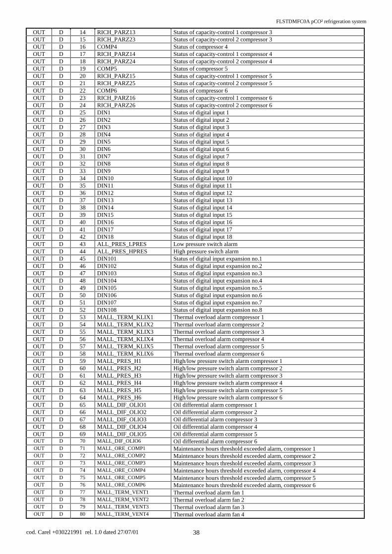
FLSTDMFC0A pCO² refrigeration system
cod. Carel +030221991 rel. 1.0 dated 27/07/01 38
OUT D 14 RICH_PARZ13 Status of capacity-control 1 compressor 3 OUT D 15 RICH_PARZ23 Status of capacity-control 2 compressor 3 OUT D 16 COMP4 Status of compressor 4 OUT D 17 RICH_PARZ14 Status of capacity-control 1 compressor 4 OUT D 18 RICH_PARZ24 Status of capacity-control 2 compressor 4 OUT D 19 COMP5 Status of compressor 5 OUT D 20 RICH_PARZ15 Status of capacity-control 1 compressor 5 OUT D 21 RICH_PARZ25 Status of capacity-control 2 compressor 5 OUT D 22 COMP6 Status of compressor 6 OUT D 23 RICH_PARZ16 Status of capacity-control 1 compressor 6 OUT D 24 RICH_PARZ26 Status of capacity-control 2 compressor 6 OUT D 25 DIN1 Status of digital input 1 OUT D 26 DIN2 Status of digital input 2 OUT D 27 DIN3 Status of digital input 3 OUT D 28 DIN4 Status of digital input 4 OUT D 29 DIN5 Status of digital input 5 OUT D 30 DIN6 Status of digital input 6 OUT D 31 DIN7 Status of digital input 7 OUT D 32 DIN8 Status of digital input 8 OUT D 33 DIN9 Status of digital input 9 OUT D 34 DIN10 Status of digital input 10 OUT D 35 DIN11 Status of digital input 11 OUT D 36 DIN12 Status of digital input 12 OUT D 37 DIN13 Status of digital input 13 OUT D 38 DIN14 Status of digital input 14 OUT D 39 DIN15 Status of digital input 15 OUT D 40 DIN16 Status of digital input 16 OUT D 41 DIN17 Status of digital input 17 OUT D 42 DIN18 Status of digital input 18 OUT D 43 ALL_PRES_LPRES Low pressure switch alarm OUT D 44 ALL_PRES_HPRES High pressure switch alarm OUT D 45 DIN101 Status of digital input expansion no.1 OUT D 46 DIN102 Status of digital input expansion no.2 OUT D 47 DIN103 Status of digital input expansion no.3 OUT D 48 DIN104 Status of digital input expansion no.4 OUT D 49 DIN105 Status of digital input expansion no.5 OUT D 50 DIN106 Status of digital input expansion no.6 OUT D 51 DIN107 Status of digital input expansion no.7 OUT D 52 DIN108 Status of digital input expansion no.8 OUT D 53 MALL_TERM_KLIX1 Thermal overload alarm compressor 1 OUT D 54 MALL_TERM_KLIX2 Thermal overload alarm compressor 2 OUT D 55 MALL_TERM_KLIX3 Thermal overload alarm compressor 3 OUT D 56 MALL_TERM_KLIX4 Thermal overload alarm compressor 4 OUT D 57 MALL_TERM_KLIX5 Thermal overload alarm compressor 5 OUT D 58 MALL_TERM_KLIX6 Thermal overload alarm compressor 6 OUT D 59 MALL_PRES_H1 High/low pressure switch alarm compressor 1 OUT D 60 MALL_PRES_H2 High/low pressure switch alarm compressor 2 OUT D 61 MALL_PRES_H3 High/low pressure switch alarm compressor 3 OUT D 62 MALL_PRES_H4 High/low pressure switch alarm compressor 4 OUT D 63 MALL_PRES_H5 High/low pressure switch alarm compressor 5 OUT D 64 MALL_PRES_H6 High/low pressure switch alarm compressor 6 OUT D 65 MALL_DIF_OLIO1 Oil differential alarm compressor 1 OUT D 66 MALL_DIF_OLIO2 Oil differential alarm compressor 2 OUT D 67 MALL_DIF_OLIO3 Oil differential alarm compressor 3 OUT D 68 MALL_DIF_OLIO4 Oil differential alarm compressor 4 OUT D 69 MALL_DIF_OLIO5 Oil differential alarm compressor 5 OUT D 70 MALL_DIF_OLIO6 Oil differential alarm compressor 6 OUT D 71 MALL_ORE_COMP1 Maintenance hours threshold exceeded alarm, compressor 1 OUT D 72 MALL_ORE_COMP2 Maintenance hours threshold exceeded alarm, compressor 2 OUT D 73 MALL_ORE_COMP3 Maintenance hours threshold exceeded alarm, compressor 3 OUT D 74 MALL_ORE_COMP4 Maintenance hours threshold exceeded alarm, compressor 4 OUT D 75 MALL_ORE_COMP5 Maintenance hours threshold exceeded alarm, compressor 5 OUT D 76 MALL_ORE_COMP6 Maintenance hours threshold exceeded alarm, compressor 6 OUT D 77 MALL_TERM_VENT1 Thermal overload alarm fan 1 OUT D 78 MALL_TERM_VENT2 Thermal overload alarm fan 2 OUT D 79 MALL_TERM_VENT3 Thermal overload alarm fan 3 OUT D 80 MALL_TERM_VENT4 Thermal overload alarm fan 4

FLSTDMFC0A pCO² refrigeration system
cod. Carel +030221991 rel. 1.0 dated 27/07/01 39
OUT D 81 mAL_LIQUID_LEVEL Liquid level alarm OUT D 82 MALL_PRES_LPRES General low pressure switch alarm OUT D 83 MALL_PRES_HPRES General high pressure switch alarm OUT D 84 mAL_LOW2 Low pressure outlet probe alarm OUT D 85 MALL_ALTA_MAND High pressure outlet probe alarm OUT D 86 mAL_LOW_PRESS Low pressure inlet probe alarm OUT D 87 mAL_HIGH_PRESS High pressure inlet probe alarm OUT D 88 mAL_N_INPUT Exceeded number of inputs available alarm OUT D 89 mAL_N_DEVICES Exceeded number of devices available alarm OUT D 90 MALL_ORA Clock fault or flat battery alarm OUT D 91 mAL_BROKEN_PR1 Inlet probe faulty or disconnected alarm OUT D 92 mAL_BROKEN_PR2 Outlet probe faulty or disconnected alarm OUT D 93 GLB_AL General alarm signal
IN/OUT D 94 RES_SIR silence buzzer IN/OUT D 95 RES_AL reset alarm relay IN/OUT D 96 CH_HOUR Hour setting IN/OUT D 97 CH_MINUTE Minute setting IN/OUT D 98 CH_DAY Day setting IN/OUT D 99 CH_MONTH Month setting IN/OUT D 100 CH_YEAR Year setting
OUT D 101 SYSON Unit status IN/OUT D 102 INPUT_LOGIC Input logic IN/OUT D 103 ALARM_LOGIC Alarm relay logic IN/OUT D 104 EN_INV_COMP Enable compressor inverter IN/OUT D 105 EN_INV_FAN Enable fan inverter IN/OUT D 106 EN_DIG_ON_OFF Enable ON/OFF from digital input IN/OUT D 108 RICH_DEFAULT Set default value IN/OUT D 110 UNLOAD_LOGIC Capacity-control logic IN/OUT D 111 SUPERV_ONOFF Select ON/OFF from supervisor IN/OUT D 112 EN_SUPERV_ONOFF Enable ON/OFF from supervisor IN/OUT D 113 EN_AL_LIQUID_LEVEL Enable liquid level alarm
OUT D 114 FAN5 Status of fan 5 OUT D 115 MALL_TERM_VENT5 Thermal overload alarm fan 5
IN/OUT D 116 EN_KEYB_ON_OFF Enable On-Off from the keypad IN/OUT D 117 EN_ALARM_RELE Enable alarm relay IN/OUT D 118 EN_ON_BALCK_OUT Enable delay at restart after Black-Out
OUT D 119 DOUT1 Status of digital output 1 OUT D 120 DOUT2 Status of digital output 2 OUT D 121 DOUT3 Status of digital output 3 OUT D 122 DOUT4 Status of digital output 4 OUT D 123 DOUT5 Status of digital output 5 OUT D 124 DOUT6 Status of digital output 6 OUT D 125 DOUT7 Status of digital output 7 OUT D 126 DOUT8 Status of digital output 8 OUT D 127 DOUT9 Status of digital output 9 OUT D 128 DOUT10 Status of digital output 10 OUT D 129 DOUT11 Status of digital output 11 OUT D 130 DOUT12 Status of digital output 12 OUT D 131 DOUT13 Status of digital output 13 OUT D 132 DOUT14 Status of digital output 14 OUT D 133 DOUT15 Status of digital output 15 OUT D 134 DOUT16 Status of digital output 16 OUT D 135 DOUT17 Status of digital output 17 OUT D 136 DOUT18 Status of digital output 18
7DEOH
,QWHJHUYDULDEOHV)ORZ 7\SH ,QGH[ 9DULDEOHQDPH 'HVFULSWLRQ
OUT I 10 IDENT identification number IN/OUT I 11 LDAY Day setting value IN/OUT I 12 LHOUR Hour setting value IN/OUT I 13 LMINUTE Minute setting value IN/OUT I 14 LMONTH Month setting value IN/OUT I 15 LYEAR Year setting value
OUT I 16 HOUR current hour OUT I 17 MINUTE current minute OUT I 18 MONTH current month

FLSTDMFC0A pCO² refrigeration system
cod. Carel +030221991 rel. 1.0 dated 27/07/01 40
OUT I 19 PYEAR current year OUT I 20 DAY current day
IN/OUT I 21 RUN_DELAY_OILD Oil differential alarm delay when running IN/OUT I 22 N_INPUT_FOR_COMP number of inputs per compressor IN/OUT I 23 N_COMP Number of compressors IN/OUT I 24 N_FAN Number of fans IN/OUT I 25 N_UNLOAD Number of capacity-control steps
OUT I 26 OUT_INV_FAN Status of analogue output 1 OUT I 27 OUT_INV_COMP Status of analogue output 2 OUT I 28 BOARD_TYPE type of board connected OUT I 29 UNIT_STATUS Unit status ("On", "OFF from alarm", "OFF from supervisor", "Restart after
Blackout", "OFF from remote input", "OFF from keypad", "Manual op.", "Default installation", "OFF from screen")
OUT I 30 TYPE_B1 type of probe b1 connected OUT I 31 TYPE_B2 type of probe b2 connected OUT I 32 BIOS_RELEASE version of bios used OUT I 33 BIOS_DATE date of bios used OUT I 34 BOOT_RELEASE version of boot used OUT I 35 BOOT_DATE date of boot used
IN/OUT I 36 INTEGR_TIME1 integration time IN/OUT I 37 TIME_SWITCH_ON1 Delay in calling compressor starts (dead zone) IN/OUT I 38 TIME_SWITCH_OFF1 Delay in calling compressor stops (dead zone) IN/OUT I 39 TIME_MIN_ON Minimum compressor ON time IN/OUT I 40 TIME_MIN_OFF Minimum compressor OFF time IN/OUT I 41 TIME_BETW_COMP Delay time between starts of different compressors IN/OUT I 42 TIME_SAME_COMP Delay time between starts of same compressor IN/OUT I 43 UNLOAD_DELAY Delay in capacity-control steps IN/OUT I 44 TIME_SWITCH_ON2 Delay in calling fan starts (dead zone) IN/OUT I 45 TIME_SWITCH_OFF2 Delay in calling fan stops (dead zone) IN/OUT I 46 TIME_BETW_FAN Delay time between starts of different fans IN/OUT I 47 RIT_DIF_OLIO Delay in oil differential alarm at start IN/OUT I 48 RIT_ALL_LIQ Delay in liquid level alarm IN/OUT I 49 MIN_OPEN_INV Minimum compressor inverter opening IN/OUT I 50 MIN_OPEN_INV2 Minimum fan inverter opening IN/OUT I 51 MIN_N_COMP_AL number of compressors forced with probe B1 faulty or disconnected IN/OUT I 52 MIN_N_FAN_AL number of fans forced with probe B2 faulty or disconnected IN/OUT I 53 SG_ORE_COMP Compressor operating hour threshold (by 1000)
OUT I 54 HOUR_COMP1 High part, operating hours compressor 1 OUT I 55 HOUR_L_COMP1 Low part, operating hours compressor 1 OUT I 56 HOUR_COMP2 High part, operating hours compressor 2 OUT I 57 HOUR_L_COMP2 Low part, operating hours compressor 2 OUT I 58 HOUR_COMP3 High part, operating hours compressor 3 OUT I 59 HOUR_L_COMP3 Low part, operating hours compressor 3 OUT I 60 HOUR_COMP4 High part, operating hours compressor 4 OUT I 61 HOUR_L_COMP4 Low part, operating hours compressor 4 OUT I 62 HOUR_COMP5 High part, operating hours compressor 5 OUT I 63 HOUR_L_COMP5 Low part, operating hours compressor 5 OUT I 64 HOUR_COMP6 High part, operating hours compressor 6 OUT I 65 HOUR_L_COMP6 Low part, operating hours compressor 6 OUT I 66 H_HOUR_FAN1 High part, operating hours fan 1 OUT I 67 L_HOUR_FAN1 Low part, operating hours fan 1 OUT I 68 H_HOUR_FAN2 High part, operating hours fan 2 OUT I 69 L_HOUR_FAN2 Low part, operating hours fan 2 OUT I 70 H_HOUR_FAN3 High part, operating hours fan 3 OUT I 71 L_HOUR_FAN3 Low part, operating hours fan 3 OUT I 72 H_HOUR_FAN4 High part, operating hours fan 4 OUT I 73 L_HOUR_FAN4 Low part, operating hours fan 4
IN/OUT I 74 SG_ORE_FAN Fan maintenance threshold alarm (by 1000) OUT I 75 VERSION version application OUT I 76 H_HOUR_FAN5 High part, operating hours fan 5 OUT I 77 L_HOUR_FAN5 Low part, operating hours fan 5 OUT I 78 TIME_ON_BLACK_OUT Minimum off time after restart from black-out OUT I 79 CONFIG_IN1 Type of device connected to input 1 OUT I 80 CONFIG_IN2 Type of device connected to input 2 OUT I 80 CONFIG_IN2 Type of device connected to input 2 OUT I 81 CONFIG_IN3 Type of device connected to input 3 OUT I 82 CONFIG_IN4 Type of device connected to input 4

FLSTDMFC0A pCO² refrigeration system
cod. Carel +030221991 rel. 1.0 dated 27/07/01 41
([DPSOHVThe versatility of the instrument means that it can be programmed in a number of ways, depending on the characteristics of the system being controlled and the type of board used. For this reason, the following tables show the input-output configurations of a number of applications. Each configuration has the following in common:
• alarm relay; • Inlet probe • Outlet probe • general high pressure switch • general low pressure switch.
Note: these three configurations are set as default for the three types of board
([DPSOHRI60$//FRQILJXUDWLRQRefrigeration system made up of:
4 fans 3 compressors (1 generic input per compressor) (0 capacity-control steps) compressor inverter fan inverter Liquid level alarm
analogue inputs
FRQQHFWRU FRGH W\SHRIDQDORJXHLQSXW GHVFULSWLRQJ2 B1 universal analogue input 1* inlet pressure probe J2 B2 universal analogue input 2* outlet pressure probe J2 GND common for analogue inputs J2 +VDC 21Vdc power supply for active probes (Imax= 200mA) J3 B4 passive analogue input 4 (NTC, PT1000, ON/OFF) general low pressure switch J3 BC4 common for analogue input 4 J3 B5 passive analogue input 5 (NTC, PT1000, ON/OFF) general high pressure switch J3 BC5 common for analogue input 5 * NTC, 0÷1V, 0÷10V, 0÷20mA, 4÷20mA 7DEOH
OUT I 83 CONFIG_IN5 Type of device connected to input 5 OUT I 84 CONFIG_IN6 Type of device connected to input 6 OUT I 85 CONFIG_IN7 Type of device connected to input 7 OUT I 86 CONFIG_IN8 Type of device connected to input 8 OUT I 87 CONFIG_IN9 Type of device connected to input 9 OUT I 88 CONFIG_IN10 Type of device connected to input 10 OUT I 89 CONFIG_IN11 Type of device connected to input 11 OUT I 90 CONFIG_IN12 Type of device connected to input 12 OUT I 91 CONFIG_IN13 Type of device connected to input 13 OUT I 92 CONFIG_IN14 Type of device connected to input 14 OUT I 93 CONFIG_IN15 Type of device connected to input 15 OUT I 94 CONFIG_IN16 Type of device connected to input 16 OUT I 95 CONFIG_IN17 Type of device connected to input 17 OUT I 96 CONFIG_IN18 Type of device connected to input 18 OUT I 97 CONFIG_OUT1 Type of device connected to output 1 OUT I 98 CONFIG_OUT2 Type of device connected to output 2 OUT I 99 CONFIG_OUT3 Type of device connected to output 3 OUT I 100 CONFIG_OUT4 Type of device connected to output 4 OUT I 101 CONFIG_OUT5 Type of device connected to output 5 OUT I 102 CONFIG_OUT6 Type of device connected to output 6 OUT I 103 CONFIG_OUT7 Type of device connected to output 7 OUT I 104 CONFIG_OUT8 Type of device connected to output 8 OUT I 105 CONFIG_OUT9 Type of device connected to output 9 OUT I 106 CONFIG_OUT10 Type of device connected to output 10 OUT I 107 CONFIG_OUT11 Type of device connected to output 11 OUT I 108 CONFIG_OUT12 Type of device connected to output 12 OUT I 109 CONFIG_OUT13 Type of device connected to output 13 OUT I 110 CONFIG_OUT14 Type of device connected to output 14 OUT I 111 CONFIG_OUT15 Type of device connected to output 15 OUT I 112 CONFIG_OUT16 Type of device connected to output 16 OUT I 113 CONFIG_OUT17 Type of device connected to output 17 OUT I 114 CONFIG_OUT18 Type of device connected to output 18
7DEOH

FLSTDMFC0A pCO² refrigeration system
cod. Carel +030221991 rel. 1.0 dated 27/07/01 42
Analogue outputs FRQQHFWRU FRGH W\SHRIDQDORJXHRXWSXW GHVFULSWLRQ
J4 VG power to optically-isolated analogue output, 24Vac/Vdc J4 VG0 power to optically-isolated analogue output,
0Vac/Vdc
J4 Y1 analogue output no. 1 0÷10V fan inverter J4 Y2 analogue output no. 2 0÷10V compressor inverter
7DEOH
Digital inputs FRQQHFWRU FRGH W\SHRIGLJLWDOLQSXW 'HVFULSWLRQ
J5 ID1 digital input no. 1, 24Vac/Vdc thermal overload comp. 1 J5 ID2 digital input no. 2, 24Vac/Vdc thermal overload comp. 2 J5 ID3 digital input no. 3, 24Vac/Vdc thermal overload comp. 3 J5 ID4 digital input no. 4, 24Vac/Vdc Liquid level J5 ID5 digital input no. 5, 24Vac/Vdc Thermal overload Klixon fan 4 J5 ID6 digital input no. 6, 24Vac/Vdc Thermal overload Klixon fan 3 J5 ID7 digital input no. 7, 24Vac/Vdc Thermal overload Klixon fan 2 J5 ID8 digital input no. 8, 24Vac/Vdc Thermal overload Klixon fan 1 7DEOH
Digital outputs FRQQHFWRU FRGH W\SHRIGLJLWDORXWSXW 'HVFULSWLRQ
J12 C1 common relay: 1, 2, 3 J12 NO1 normally-open contact, relay no. 1 Compressor 1 J12 NO2 normally-open contact, relay no. 2 Compressor 2 J12 NO3 normally-open contact, relay no. 3 Compressor 3 J12 C1 common relay: 1, 2, 3 J13 C4 common relay: 4, 5, 6 J13 NO4 normally-open contact, relay no. 4 General alarm J13 NO5 normally-open contact, relay no. 5 fan 4 J13 NO6 normally-open contact, relay no. 6 fan 3 J13 C4 common relay: 4, 5, 6 J14 C7 common relay no. 7 J14 NO7 normally-open contact, relay no. 7 fan 2 J14 C7 common relay no. 7 J15 NO8 normally-open contact, relay no. 8 fan 1 J15 C8 common relay no. 8
7DEOH
([DPSOHRI0(',80FRQILJXUDWLRQRefrigeration system made up of: 4 fans 4 compressors (2 inputs per compressor) (1 capacity-control step per compressor) fan inverter Liquid level alarm and On-Off from digital input
Analogue inputs
FRQQHFWRU FRGH W\SHRIDQDORJXHLQSXW 'HVFULSWLRQJ2 B1 universal analogue input 1* inlet pressure probe J2 B2 universal analogue input 2* outlet pressure probe J2 GND common for analogue inputs J2 +VDC 21Vdc power supply for active probes (Imax= 200mA) J3 B4 passive analogue input 4 (NTC, PT1000, ON/OFF) general low pressure switch J3 BC4 common for analogue input 4 J3 B5 passive analogue input 5 (NTC, PT1000, ON/OFF) general high pressure switch J3 BC5 common for analogue input 5 * NTC, 0÷1V, 0÷10V, 0÷20mA, 4÷20mA 7DEOH
Analogue outputs FRQQHFWRU FRGH W\SHRIDQDORJXHRXWSXW 'HVFULSWLRQ
J4 VG power to optically-isolated analogue output, 24Vac/Vdc J4 VG0 power to optically-isolated analogue output, 0Vac/Vdc J4 Y1 analogue output no. 1 0÷10V fan inverter J4 Y2 analogue output no. 2 0÷10V compressor inverter
7DEOH

FLSTDMFC0A pCO² refrigeration system
cod. Carel +030221991 rel. 1.0 dated 27/07/01 43
Digital inputs FRQQHFWRU FRGH W\SHRIGLJLWDOLQSXW 'HVFULSWLRQ
J5 ID1 digital input no. 1, 24Vac/Vdc thermal overload comp. 1 J5 ID2 digital input no. 2, 24Vac/Vdc thermal overload comp. 2 J5 ID3 digital input no. 3, 24Vac/Vdc thermal overload comp. 3 J5 ID4 digital input no. 4, 24Vac/Vdc thermal overload comp. 4 J5 ID5 digital input no. 5, 24Vac/Vdc oil differential 1 J5 ID6 digital input no. 6, 24Vac/Vdc oil differential 2 J5 ID7 digital input no. 7, 24Vac/Vdc oil differential 3 J5 ID8 digital input no. 8, 24Vac/Vdc oil differential 4 J5 IDC1 common for digital inputs 1 to 8 J7 ID9 digital input no. 9, 24Vac/Vdc Liquid level J7 ID10 digital input no. 10, 24Vac/Vdc On-Off from digital input J7 ID11 digital input no. 11, 24Vac/Vdc Thermal overload Klixon fan 4 J7 ID12 digital input no. 12, 24Vac/Vdc Thermal overload Klixon fan 3 J7 IDC9 common for digital inputs 9 to 12 J8 ID13 digital input 13, 24Vac/Vdc Thermal overload Klixon fan 2 J8 IDC13 common for digital inputs 13 and 14 J8 ID14 digital input 14, 24Vac/Vdc Thermal overload Klixon fan 1 Table 6.3.2.3
Digital outputs FRQQHFWRU FRGH type of digital output 'HVFULSWLRQ
J12 C1 common relay: 1, 2, 3 J12 NO1 normally-open contact, relay no. 1 Compressor 1 J12 NO2 normally-open contact, relay no. 2 capacity-control 1 compressor 1 J12 NO3 normally-open contact, relay no. 3 Compressor 2 J12 C1 common relay: 1, 2, 3 J13 C4 common relay: 4, 5, 6 J13 NO4 normally-open contact, relay no. 4 capacity-control 1 compressor 2 J13 NO5 normally-open contact, relay no. 5 Compressor 3 J13 NO6 normally-open contact, relay no. 6 capacity-control 1 compressor 3 J13 C4 common relay: 4, 5, 6 J14 C7 common relay no. 7 J14 NO7 normally-open contact, relay no. 7 Compressor 4 J14 C7 common relay no. 7 J15 NO8 normally-open contact, relay no. 8 capacity-control 1 compressor 4 J15 C8 common relay no. 8 J16 C9 common relay no. 9 J16 NO9 normally-open contact, relay no. 9 General alarm J16 NO10 normally-open contact, relay no. 10 fan 4 J16 NO11 normally-open contact, relay no. 11 fan 3 J16 C9 common relay no. 9 J17 NO12 normally-open contact, relay no. 12 fan 2 J17 C12 common relay no. 12 J18 NO13 normally-open contact, relay no. 13 fan 1 J18 C13 common relay no. 13
Table 6.3.2.4
([DPSOHRI/$5*(FRQILJXUDWLRQ4 fans 5 compressors (3 inputs per compressor) (1 capacity-control step per
compressor) fan inverter
Liquid level alarm analogue inputs
FRQQHFWRU FRGH W\SHRIDQDORJXHLQSXW 'HVFULSWLRQJ2 B1 universal analogue input 1* inlet pressure probe J2 B2 universal analogue input 2* outlet pressure probe J2 GND common for analogue inputs J2 +VDC 21Vdc power supply for active probes (Imax= 200mA) J3 B4 passive analogue input 4 (NTC, PT1000, ON/OFF) general low pressure switch J3 BC4 common for analogue input 4 J3 B5 passive analogue input 5 (NTC, PT1000, ON/OFF) general high pressure switch J3 BC5 common for analogue input 5

FLSTDMFC0A pCO² refrigeration system
cod. Carel +030221991 rel. 1.0 dated 27/07/01 44
J20- B9 passive analogue input 9 (NTC, PT1000, ON/OFF) Thermal overload Klixon fan 1 J20- BC9 common analogue input 9 J20- B10 passive analogue input 9 (NTC, PT1000, ON/OFF) Thermal overload Klixon fan 2 J20- BC10 common analogue input 10
* NTC, 0÷1 V, 0÷10V, 0÷20mA, 4÷20mA 7DEOH
Analogue outputs FRQQHFWRU FRGH W\SHRIDQDORJXHRXWSXW 'HVFULSWLRQ
J4 VG power to optically-isolated analogue output, 24Vac/Vdc J4 VG0 power to optically-isolated analogue output, 0Vac/Vdc J4 Y1 analogue output no. 1 0÷10V fan inverter J4 Y2 analogue output no. 2 0÷10V compressor inverter
7DEOH Digital inputs FRQQHFWRU FRGH type of digital input 'HVFULSWLRQ
J5 ID1 digital input no. 1, 24Vac/Vdc thermal overload comp. 1 J5 ID2 digital input no. 2, 24Vac/Vdc thermal overload comp. 2 J5 ID3 digital input no. 3, 24Vac/Vdc thermal overload comp. 3 J5 ID4 digital input no. 4, 24Vac/Vdc thermal overload comp. 4 J5 ID5 digital input no. 5, 24Vac/Vdc thermal overload comp. 5 J5 ID6 digital input no. 6, 24Vac/Vdc oil differential 1 J5 ID7 digital input no. 7, 24Vac/Vdc oil differential 2 J5 ID8 digital input no. 8, 24Vac/Vdc oil differential 3 J5 IDC1 common for digital inputs 1 to 8 J7 ID9 digital input no. 9, 24Vac/Vdc oil differential 4 J7 ID10 digital input no. 10, 24Vac/Vdc oil differential 5 J7 ID11 digital input no. 11, 24Vac/Vdc High-low pressure switch 1 J7 ID12 digital input no. 12, 24Vac/Vdc High-low pressure switch 2 J7 IDC9 common for digital inputs 9 to 12 J8 ID13 digital input 13, 24Vac/Vdc High-low pressure switch 3 J8 IDC13 common for digital inputs 13 and 14 J8 ID14 digital input 14, 24Vac/Vdc High-low pressure switch 4 J19 ID15 digital input 15, 24Vac/Vdc High-low pressure switch 5 J19 IDC15 common for digital inputs 15 and 16 J19 ID16 digital input 16, 24Vac/Vdc Liquid level alarm J20 ID17 digital input 17, 24Vac/Vdc Thermal overload Klixon fan 4 J20 ID18 digital input 18, 24Vac/Vdc Thermal overload Klixon fan 3 J20 IDC17 common for digital inputs 17 and 18
7DEOH Digital outputs FRQQHFWRU FRGH W\SHRIGLJLWDORXWSXW 'HVFULSWLRQ
J12 C1 common relay: 1, 2, 3 J12 NO1 normally-open contact, relay no. 1 compressor 1 J12 NO2 normally-open contact, relay no. 2 capacity-control 1 compressor 1 J12 NO3 normally-open contact, relay no. 3 compressor 2 J12 C1 common relay: 1, 2, 3 J13 C4 common relay: 4, 5, 6 J13 NO4 normally-open contact, relay no. 4 capacity-control 1 compressor 2 J13 NO5 normally-open contact, relay no. 5 compressor 3 J13 NO6 normally-open contact, relay no. 6 capacity-control 1 compressor 3 J13 C4 common relay: 4, 5, 6 J14 C7 common relay no. 7 J14 NO7 normally-open contact, relay no. 7 compressor 4 J14 C7 common relay no. 7 J15 NO8 normally-open contact, relay no. 8 capacity-control 1 compressor 4 J15 C8 common relay no. 8 J16 C9 common relay no. 9 J16 NO9 normally-open contact, relay no. 9 compressor 5 J16 NO10 normally-open contact, relay no. 10 capacity-control 1 compressor 4 J16 NO11 normally-open contact, relay no. 11 J16 C9 common relay no. 9 J17 NO12 normally-open contact, relay no. 12 / J17 C12 common relay no. 12 J18 NO13 normally-open contact, relay no. 13 / J18 C13 common relay no. 13
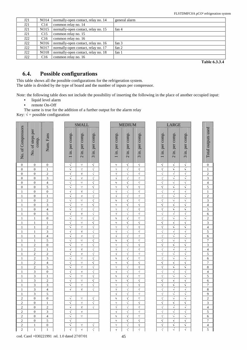
FLSTDMFC0A pCO² refrigeration system
cod. Carel +030221991 rel. 1.0 dated 27/07/01 45
J21 NO14 normally-open contact, relay no. 14 general alarm J21 C14 common relay no. 14 J21 NO15 normally-open contact, relay no. 15 fan 4 J21 C15 common relay no. 15 J22 C16 common relay no. 16 J22 NO16 normally-open contact, relay no. 16 fan 3 J22 NO17 normally-open contact, relay no. 17 fan 2 J22 NO18 normally-open contact, relay no. 18 fan 1 J22 C16 common relay no. 16
7DEOH
3RVVLEOHFRQILJXUDWLRQVThis table shows all the possible configurations for the refrigeration system. The table is divided by the type of board and the number of inputs per compressor. Note: the following table does not include the possibility of inserting the following in the place of another occupied input:
• liquid level alarm • remote On-Off The same is true for the addition of a further output for the alarm relay
Key: ¥ = possible configuration
SMALL MEDIUM LARGE
No.
of
Com
pres
sors
No.
of
step
s pe
r co
mp.
Num
. Fan
s
1 in
. per
com
p.
2 in
. per
com
p.
3 in
. per
com
p.
1 in
. per
com
p.
2 in
. per
com
p.
3 in
. per
com
p.
1
in. p
er c
omp.
2 in
. per
com
p.
3 in
. per
com
p.
Tot
al o
utpu
ts u
sed
0 0 0 ¥ ¥ ¥ ¥ ¥ ¥ ¥ ¥ ¥ 0 0 0 1 ¥ ¥ ¥ ¥ ¥ ¥ ¥ ¥ ¥ 1 0 0 2 ¥ ¥ ¥ ¥ ¥ ¥ ¥ ¥ ¥ 2 0 0 3 ¥ ¥ ¥ ¥ ¥ ¥ ¥ ¥ ¥ 3 0 0 4 ¥ ¥ ¥ ¥ ¥ ¥ ¥ ¥ ¥ 4 0 0 5 ¥ ¥ ¥ ¥ ¥ ¥ ¥ ¥ ¥ 5 1 0 0 ¥ ¥ ¥ ¥ ¥ ¥ ¥ ¥ ¥ 1 1 0 1 ¥ ¥ ¥ ¥ ¥ ¥ ¥ ¥ ¥ 2 1 0 2 ¥ ¥ ¥ ¥ ¥ ¥ ¥ ¥ ¥ 3 1 0 3 ¥ ¥ ¥ ¥ ¥ ¥ ¥ ¥ ¥ 4 1 0 4 ¥ ¥ ¥ ¥ ¥ ¥ ¥ ¥ ¥ 5 1 0 5 ¥ ¥ ¥ ¥ ¥ ¥ ¥ ¥ ¥ 6 1 1 0 ¥ ¥ ¥ ¥ ¥ ¥ ¥ ¥ ¥ 2 1 1 1 ¥ ¥ ¥ ¥ ¥ ¥ ¥ ¥ ¥ 3 1 1 2 ¥ ¥ ¥ ¥ ¥ ¥ ¥ ¥ ¥ 4 1 1 3 ¥ ¥ ¥ ¥ ¥ ¥ ¥ ¥ ¥ 5 1 1 4 ¥ ¥ ¥ ¥ ¥ ¥ ¥ ¥ ¥ 6 1 1 5 ¥ ¥ ¥ ¥ ¥ ¥ ¥ ¥ ¥ 7 1 2 0 ¥ ¥ ¥ ¥ ¥ ¥ ¥ ¥ ¥ 3 1 2 1 ¥ ¥ ¥ ¥ ¥ ¥ ¥ ¥ ¥ 4 1 2 2 ¥ ¥ ¥ ¥ ¥ ¥ ¥ ¥ ¥ 5 1 2 3 ¥ ¥ ¥ ¥ ¥ ¥ ¥ ¥ ¥ 6 1 2 4 ¥ ¥ ¥ ¥ ¥ ¥ ¥ ¥ ¥ 7 1 2 5 ¥ ¥ ¥ ¥ ¥ ¥ ¥ ¥ ¥ 8 1 3 0 ¥ ¥ ¥ ¥ ¥ ¥ ¥ ¥ ¥ 4 1 3 1 ¥ ¥ ¥ ¥ ¥ ¥ ¥ ¥ ¥ 5 1 3 2 ¥ ¥ ¥ ¥ ¥ ¥ ¥ ¥ ¥ 6 1 3 3 ¥ ¥ ¥ ¥ ¥ ¥ ¥ ¥ ¥ 7 1 3 4 ¥ ¥ ¥ ¥ ¥ ¥ ¥ ¥ ¥ 8 1 3 5 ¥ ¥ ¥ ¥ ¥ ¥ 9 2 0 0 ¥ ¥ ¥ ¥ ¥ ¥ ¥ ¥ ¥ 2 2 0 1 ¥ ¥ ¥ ¥ ¥ ¥ ¥ ¥ ¥ 3 2 0 2 ¥ ¥ ¥ ¥ ¥ ¥ ¥ ¥ ¥ 4 2 0 3 ¥ ¥ ¥ ¥ ¥ ¥ ¥ ¥ 5 2 0 4 ¥ ¥ ¥ ¥ ¥ ¥ ¥ ¥ 6 2 0 5 ¥ ¥ ¥ ¥ ¥ ¥ ¥ 7 2 1 0 ¥ ¥ ¥ ¥ ¥ ¥ ¥ ¥ ¥ 4 2 1 1 ¥ ¥ ¥ ¥ ¥ ¥ ¥ ¥ ¥ 5

FLSTDMFC0A pCO² refrigeration system
cod. Carel +030221991 rel. 1.0 dated 27/07/01 46
2 1 2 ¥ ¥ ¥ ¥ ¥ ¥ ¥ ¥ ¥ 6 2 1 3 ¥ ¥ ¥ ¥ ¥ ¥ ¥ ¥ 7 2 1 4 ¥ ¥ ¥ ¥ ¥ ¥ ¥ ¥ 8 2 1 5 ¥ ¥ ¥ ¥ ¥ ¥ 9 2 2 0 ¥ ¥ ¥ ¥ ¥ ¥ ¥ ¥ ¥ 6 2 2 1 ¥ ¥ ¥ ¥ ¥ ¥ ¥ ¥ ¥ 7 2 2 2 ¥ ¥ ¥ ¥ ¥ ¥ ¥ ¥ ¥ 8 2 2 3 ¥ ¥ ¥ ¥ ¥ ¥ 9 2 2 4 ¥ ¥ ¥ ¥ ¥ ¥ 10 2 2 5 ¥ ¥ ¥ ¥ ¥ ¥ 11 2 3 0 ¥ ¥ ¥ ¥ ¥ ¥ ¥ ¥ ¥ 8 2 3 1 ¥ ¥ ¥ ¥ ¥ ¥ 9 2 3 2 ¥ ¥ ¥ ¥ ¥ ¥ 10 2 3 3 ¥ ¥ ¥ ¥ ¥ ¥ 11 2 3 4 ¥ ¥ ¥ ¥ ¥ ¥ 12 2 3 5 ¥ ¥ ¥ ¥ ¥ ¥ 13 3 0 0 ¥ ¥ ¥ ¥ ¥ ¥ ¥ ¥ 3 3 0 1 ¥ ¥ ¥ ¥ ¥ ¥ ¥ ¥ 4 3 0 2 ¥ ¥ ¥ ¥ ¥ ¥ ¥ ¥ 5 3 0 3 ¥ ¥ ¥ ¥ ¥ ¥ ¥ 6 3 0 4 ¥ ¥ ¥ ¥ ¥ ¥ ¥ 7 3 0 5 ¥ ¥ ¥ ¥ ¥ ¥ ¥ 8 3 1 0 ¥ ¥ ¥ ¥ ¥ ¥ ¥ ¥ 6 3 1 1 ¥ ¥ ¥ ¥ ¥ ¥ ¥ ¥ 7 3 1 2 ¥ ¥ ¥ ¥ ¥ ¥ ¥ ¥ 8 3 1 3 ¥ ¥ ¥ ¥ ¥ ¥ 9 3 1 4 ¥ ¥ ¥ ¥ ¥ ¥ 10 3 1 5 ¥ ¥ ¥ ¥ ¥ ¥ 11 3 2 0 ¥ ¥ ¥ ¥ ¥ ¥ 9 3 2 1 ¥ ¥ ¥ ¥ ¥ ¥ 10 3 2 2 ¥ ¥ ¥ ¥ ¥ ¥ 11 3 2 3 ¥ ¥ ¥ ¥ ¥ ¥ 12 3 2 4 ¥ ¥ ¥ ¥ ¥ ¥ 13 3 2 5 ¥ ¥ ¥ 14 3 3 0 ¥ ¥ ¥ ¥ ¥ ¥ 12 3 3 1 ¥ ¥ ¥ ¥ ¥ ¥ 13 3 3 2 ¥ ¥ ¥ 14 3 3 3 ¥ ¥ ¥ 15 3 3 4 ¥ ¥ ¥ 16 3 3 5 ¥ ¥ ¥ 17 4 0 0 ¥ ¥ ¥ ¥ ¥ ¥ ¥ ¥ 4 4 0 1 ¥ ¥ ¥ ¥ ¥ ¥ ¥ 5 4 0 2 ¥ ¥ ¥ ¥ ¥ ¥ ¥ 6 4 0 3 ¥ ¥ ¥ ¥ ¥ ¥ 7 4 0 4 ¥ ¥ ¥ ¥ ¥ ¥ 8 4 0 5 ¥ ¥ ¥ ¥ ¥ 9 4 1 0 ¥ ¥ ¥ ¥ ¥ ¥ ¥ ¥ 8 4 1 1 ¥ ¥ ¥ ¥ ¥ ¥ 9 4 1 2 ¥ ¥ ¥ ¥ ¥ ¥ 10 4 1 3 ¥ ¥ ¥ ¥ ¥ 11 4 1 4 ¥ ¥ ¥ ¥ ¥ 12 4 1 5 ¥ ¥ ¥ ¥ ¥ 13 4 2 0 ¥ ¥ ¥ ¥ ¥ ¥ 12 4 2 1 ¥ ¥ ¥ ¥ ¥ ¥ 13 4 2 2 ¥ ¥ ¥ 14 4 2 3 ¥ ¥ ¥ 15 4 2 4 ¥ ¥ ¥ 16 4 2 5 ¥ ¥ ¥ 17 4 3 0 ¥ ¥ ¥ 16 4 3 1 ¥ ¥ ¥ 17 4 3 2 ¥ ¥ ¥ 18 4 3 3 19 4 3 4 20 5 3 5 25 5 0 0 ¥ ¥ ¥ ¥ ¥ ¥ 5 5 0 1 ¥ ¥ ¥ ¥ ¥ ¥ 6 5 0 2 ¥ ¥ ¥ ¥ ¥ ¥ 7 5 0 3 ¥ ¥ ¥ ¥ ¥ ¥ 8 5 0 4 ¥ ¥ ¥ ¥ ¥ 9 5 0 5 ¥ ¥ ¥ ¥ 10

FLSTDMFC0A pCO² refrigeration system
cod. Carel +030221991 rel. 1.0 dated 27/07/01 47
5 1 0 ¥ ¥ ¥ ¥ ¥ 10 5 1 1 ¥ ¥ ¥ ¥ ¥ 11 5 1 2 ¥ ¥ ¥ ¥ ¥ 12 5 1 3 ¥ ¥ ¥ ¥ ¥ 13 5 1 4 ¥ ¥ ¥ 14 5 1 5 ¥ ¥ ¥ 15 5 2 0 ¥ ¥ ¥ 15 5 2 1 ¥ ¥ ¥ 16 5 2 2 ¥ ¥ ¥ 17 5 2 3 ¥ ¥ ¥ 18 5 2 4 19 5 2 5 20 5 3 0 20 5 3 1 21 5 3 2 22 5 3 3 23 5 3 4 24 5 3 5 25 6 0 0 ¥ ¥ ¥ ¥ ¥ ¥ 6 6 0 1 ¥ ¥ ¥ ¥ ¥ ¥ 7 6 0 2 ¥ ¥ ¥ ¥ ¥ ¥ 8 6 0 3 ¥ ¥ ¥ 9 6 0 4 ¥ ¥ ¥ 10 6 0 5 ¥ ¥ ¥ 11 6 1 0 ¥ ¥ ¥ ¥ ¥ 12 6 1 1 ¥ ¥ ¥ ¥ ¥ 13 6 1 2 ¥ ¥ ¥ 14 6 1 3 ¥ ¥ 15 6 1 4 ¥ ¥ 16 6 1 5 ¥ ¥ 17 6 2 0 ¥ ¥ ¥ 18 6 2 1 19 6 2 2 20 6 2 3 21 6 2 4 22 6 2 5 23 6 3 0 24 6 3 1 25 6 3 2 26 6 3 3 27 6 3 4 28 6 3 5 29
Carel reserves the right to modify or change its products without prior warning.

1RWHV________________________________________________________________________________
BBBBBBBBBBBBBBBBBBBBBBBBBBBBBBBBBBBBBBBBBBBBBBBBBBBBBBBBBBBBBBBBBBBBBBBBBBBBBBBBBBBBB
BBBBBBBBBBBBBBBBBBBBBBBBBBBBBBBBBBBBBBBBBBBBBBBBBBBBBBBBBBBBBBBBBBBBBBBBBBBBBBBBBBBBB
BBBBBBBBBBBBBBBBBBBBBBBBBBBBBBBBBBBBBBBBBBBBBBBBBBBBBBBBBBBBBBBBBBBBBBBBBBBBBBBBBBBBB
BBBBBBBBBBBBBBBBBBBBBBBBBBBBBBBBBBBBBBBBBBBBBBBBBBBBBBBBBBBBBBBBBBBBBBBBBBBBBBBBBBBBB
BBBBBBBBBBBBBBBBBBBBBBBBBBBBBBBBBBBBBBBBBBBBBBBBBBBBBBBBBBBBBBBBBBBBBBBBBBBBBBBBBBBBB
BBBBBBBBBBBBBBBBBBBBBBBBBBBBBBBBBBBBBBBBBBBBBBBBBBBBBBBBBBBBBBBBBBBBBBBBBBBBBBBBBBBBB
BBBBBBBBBBBBBBBBBBBBBBBBBBBBBBBBBBBBBBBBBBBBBBBBBBBBBBBBBBBBBBBBBBBBBBBBBBBBBBBBBBBBB
BBBBBBBBBBBBBBBBBBBBBBBBBBBBBBBBBBBBBBBBBBBBBBBBBBBBBBBBBBBBBBBBBBBBBBBBBBBBBBBBBBBBB
BBBBBBBBBBBBBBBBBBBBBBBBBBBBBBBBBBBBBBBBBBBBBBBBBBBBBBBBBBBBBBBBBBBBBBBBBBBBBBBBBBBBB
BBBBBBBBBBBBBBBBBBBBBBBBBBBBBBBBBBBBBBBBBBBBBBBBBBBBBBBBBBBBBBBBBBBBBBBBBBBBBBBBBBBBB
BBBBBBBBBBBBBBBBBBBBBBBBBBBBBBBBBBBBBBBBBBBBBBBBBBBBBBBBBBBBBBBBBBBBBBBBBBBBBBBBBBBBB
BBBBBBBBBBBBBBBBBBBBBBBBBBBBBBBBBBBBBBBBBBBBBBBBBBBBBBBBBBBBBBBBBBBBBBBBBBBBBBBBBBBBB
BBBBBBBBBBBBBBBBBBBBBBBBBBBBBBBBBBBBBBBBBBBBBBBBBBBBBBBBBBBBBBBBBBBBBBBBBBBBBBBBBBBBB
BBBBBBBBBBBBBBBBBBBBBBBBBBBBBBBBBBBBBBBBBBBBBBBBBBBBBBBBBBBBBBBBBBBBBBBBBBBBBBBBBBBBB
BBBBBBBBBBBBBBBBBBBBBBBBBBBBBBBBBBBBBBBBBBBBBBBBBBBBBBBBBBBBBBBBBBBBBBBBBBBBBBBBBBBBB
BBBBBBBBBBBBBBBBBBBBBBBBBBBBBBBBBBBBBBBBBBBBBBBBBBBBBBBBBBBBBBBBBBBBBBBBBBBBBBBBBBBBB
BBBBBBBBBBBBBBBBBBBBBBBBBBBBBBBBBBBBBBBBBBBBBBBBBBBBBBBBBBBBBBBBBBBBBBBBBBBBBBBBBBBBB
BBBBBBBBBBBBBBBBBBBBBBBBBBBBBBBBBBBBBBBBBBBBBBBBBBBBBBBBBBBBBBBBBBBBBBBBBBBBBBBBBBBBB
BBBBBBBBBBBBBBBBBBBBBBBBBBBBBBBBBBBBBBBBBBBBBBBBBBBBBBBBBBBBBBBBBBBBBBBBBBBBBBBBBBBBB
BBBBBBBBBBBBBBBBBBBBBBBBBBBBBBBBBBBBBBBBBBBBBBBBBBBBBBBBBBBBBBBBBBBBBBBBBBBBBBBBBBBBB
BBBBBBBBBBBBBBBBBBBBBBBBBBBBBBBBBBBBBBBBBBBBBBBBBBBBBBBBBBBBBBBBBBBBBBBBBBBBBBBBBBBBB
BBBBBBBBBBBBBBBBBBBBBBBBBBBBBBBBBBBBBBBBBBBBBBBBBBBBBBBBBBBBBBBBBBBBBBBBBBBBBBBBBBBBB
BBBBBBBBBBBBBBBBBBBBBBBBBBBBBBBBBBBBBBBBBBBBBBBBBBBBBBBBBBBBBBBBBBBBBBBBBBBBBBBBBBBBB
BBBBBBBBBBBBBBBBBBBBBBBBBBBBBBBBBBBBBBBBBBBBBBBBBBBBBBBBBBBBBBBBBBBBBBBBBBBBBBBBBBBBB
BBBBBBBBBBBBBBBBBBBBBBBBBBBBBBBBBBBBBBBBBBBBBBBBBBBBBBBBBBBBBBBBBBBBBBBBBBBBBBBBBBBBB
BBBBBBBBBBBBBBBBBBBBBBBBBBBBBBBBBBBBBBBBBBBBBBBBBBBBBBBBBBBBBBBBBBBBBBBBBBBBBBBBBBBBB


&$5(/VUO Via dell’Industria, 11 - 35020 Brugine - Padova (Italy) Tel. (+39) 049.9716611 Fax (+39) 049.9716600 http://www.carel.com - e-mail: [email protected]
Agency:
Cod
. Car
el +
0302
2199
1 r
el. 1
.0 -
27/
07/0
1