Danuše Bauerová VŠB – Technical University Ostrava, Czech Republic

VŠB - Technical University of Ostrava
Faculty of Metallurgy and Materials Engineering
MOULDING MIXTURES (E-LEARNING)
Jaroslav Beňo
Petr Jelínek
Nikol Špirutová
Ostrava, 2015

2
Name: Moulding mixtures
Author: Ing. Jaroslav Beňo, Ph. D.
Prof. Ing. Petr Jelínek, CSc., Dr. h. c.
Ing. Nikol Špirutová
Issue: first, 2015
Number of pages: 168
Educational materials for the branch Modern Metallurgical Technologies (study
programme Metallurgical engineering) of the Master’s study at the Faculty of
Metallurgy and Materials Engineering
Proof-reading: not performed
© Jaroslav Beňo
© VŠB - Technical University of Ostrava

TABLE OF CONTENTS
3
TABLE OF CONTENTS
1 BASE SANDS ................................................................................................ 6
1.1 General classification of base sands .......................................................................... 6
1.2 Silica sands ................................................................................................................ 7
1.3 Disadvantages of silica sands .................................................................................... 9
1.3.1 Increased reactivity of silica sands ................................................................... 10
1.3.2 Discontinuous thermal dilatation ...................................................................... 10
1.3.3 Cristobalite expansion ...................................................................................... 12
1.4 Non-silica sands ....................................................................................................... 16
1.4.1 Chamotte schist ................................................................................................. 17
1.4.2 Corundum ......................................................................................................... 18
1.4.3 Chromite ........................................................................................................... 19
1.4.4 Zirconium-silicate ............................................................................................. 20
1.4.5 Olivine .............................................................................................................. 21
1.5 Granulometric composition of sands ....................................................................... 23
1.5.1 Cumulative curve of granularity ....................................................................... 23
1.5.2 Log W criterion ................................................................................................ 26
1.6 Angularity coefficient of sand ................................................................................. 27
1.7 Thermal conductivity (cooling effect) of a foundry mould ..................................... 30
1.7.1 Cooling effect of non-silica base sands ............................................................ 33
2 REGENERATION OF MOULDING SAND MIXTURES ..................... 34
3 STRENGTH OF MOULDING SAND MIXTURES ............................... 35
3.1 Strength of moulding sand mixtures as a result of adhesion – cohesion forces of a
binder ................................................................................................................................. 37
4 BINDER SYSTEMS OF THE IST GENERATION MOULDING
SAND MIXTURES ................................................................................... 38
4.1 Clay binders ............................................................................................................. 38
4.2 Water in clay minerals ............................................................................................. 39
4.3 Bentonite and bentonite mixtures ............................................................................ 40
4.3.1 Natrification of bentonite and its consequences ............................................... 42
4.4 Additives for bentonite mixtures ............................................................................. 44
4.4.1 Saccharides ....................................................................................................... 45
4.4.2 Oxidants ............................................................................................................ 45
4.4.3 Graphite ............................................................................................................ 45

TABLE OF CONTENTS
4
4.4.4 Carriers of lustrous carbon ............................................................................... 46
5 BINDER SYSTEMS OF THE IIND GENERATION SAND
MIXTURES – INORGANIC BINDERS ................................................ 49
5.1 Moulding sand mixtures with water glass ............................................................... 49
5.1.1 Hardening procedures for mixtures with water glass ....................................... 49
5.1.2 Water glass module .......................................................................................... 49
5.1.3 Coagulation threshold of water glass ................................................................ 50
5.2 CO2 process ............................................................................................................. 51
5.2.1 By-products of the hardening reaction ............................................................. 55
5.3 Self-hardening mixtures with water glass ................................................................ 56
5.3.1 Physical – chemical processes of hardening of water glass by liquid hardening
agents 56
5.3.2 Reactivity and optimal concentration of an ester-type hardening agent........... 58
5.4 Problems of collapsibility of mixtures with water glass .......................................... 60
5.4.1 Critical analysis of residual strength of a mixture with water glass and silica
sand (CO2-process) ....................................................................................................... 60
5.4.2 An increase in residual strength and the Ist maximum area ............................. 60
5.4.3 Decrease in residual strength behind the Ist maximum and area of the Ist
minimum (approximately 600°C) ................................................................................ 61
5.4.4 Sharp growth of residual strength behind the Ist minimum and the area of IInd
maximum (800900°C) ................................................................................................ 61
5.4.5 Decrease in residual strength behind the IInd maximum (the IInd minimum). 62
5.4.6 Possibilities of control of residual strength with water glass (CO2 – process) . 62
5.5 Hardening of alkaline silicates by dehydration processes ....................................... 63
5.5.1 Collapsibility of cores ....................................................................................... 63
6 BINDER SYSTEMS OF THE IIND GENERATION SAND
MIXTURES – ORGANIC BINDERS ..................................................... 63
6.1 Organic-based foundry binders ................................................................................ 63
6.1.1 Chemistry of phenolic binders .......................................................................... 64
6.1.2 Shell moulding, the Croning method, “C” method .......................................... 64
6.1.3 Hot-Box method ............................................................................................... 67
6.1.4 Cold-Box method ............................................................................................. 68
6.2 Chemistry of furan binders ...................................................................................... 71
6.2.1 Self-hardening furan mixtures .......................................................................... 71
6.2.2 Cold processes – extrinsic hardening ............................................................... 72
TABLE OF CONTENTS
5
6.2.3 SO2 – process (furan resin) ................................................................................ 72
6.2.4 Resol-CO2 ......................................................................................................... 74
6.3 Chemistry of polyurethane binders .......................................................................... 75
6.3.1 Phenolic polyurethane system .......................................................................... 75

Sands – General clasification
6
1 Sands
1.1 General classification of sands
Sand grains, a heat resistant material with a particle size above 0.02 mm, has the main
volume weight apportionment in a mixture. It forms a material skeleton of moulds and cores,
therefore angularity and granulometry of particles belong among its most important properties
aside from the activity of grain surfaces. Angularity and granulometry of particles are decisive
for volume weight, porosity and ensuing permeability and penetrability of a mixture, thermal
dilatation and generation of tension from braked dilatation, thermal conductivity of a mixture
and affect even strength of moulds and cores to a large extent.
A sand particle size of 0.02 mm is considered critical. Smaller particles belong to a
flushable fraction – clays, silica dust, non-plastic particles, spar, other minerals – clay binder
(determination of flush ability by a test, ČSN 721078).
To calculate a sedimentation setting velocity in water (v) and determine flushable
fractions in sands (silica sand can be obtained by washing sands), the Stokes law is used
(applies for particles between 0.001 – 0.1 mm):
122
9
2v
rg (1)
where: g – gravitation
r – a particle radius
2 – base sand specific weight
1 – water specific weight
– water dynamic viscosity
Elutriation of the sand – water suspension is performed in the presence of 5% solution
of NaOH (pursuant to the Czech standard). A dispersing agent prevents aggregation of fine
(colloid) particles. Aggregates have different sedimentation setting velocities and distort
results of the sedimentation analysis.
Washed sands, nowadays used for preparation of synthetic mixtures with inorganic
binders, should not contain more than 1 % of flushable particles. For synthetic resins even
lower concentration is required.
Sands are divided according to the chemical character:
- Acidic (silica sands)
- Neutral (chamotte, corundum)
Sands – General clasification
7
- Alkaline (magnesite, olivine)
Acidic sands react with alkaline oxides of alloyed steels, leading to formation of
compounds with lower heat resistance. As a result of these chemical reactions, burning-on
and burning-in (metal penetration) occur on castings. Therefore Mn steels cannot be cast into
silica sands. For thin-walled castings, the both chemically different oxides can be isolated
from a contact with each other by application of a base or neutral coating (magnesite,
corundum).
Sands are divided according to the origin:
- Natural (silica sands, olivine, disthen-sillimanite, zirconium-silicate)
- Artificial (ground chamotte, corundum, metal beads, Cerabeads)
The selection of a sand type for preparation of a mixture must meet the following criteria:
- A chemical character of the cast alloy (a type of the alloyed material)
- A type of the cast alloy (steel - cast iron); casting temperature, permissible
content of feldspars in sand
- A shape complexity and wall thickness in a casting (susceptibility to
occurrence of casting defects - burning-in, scabs)
- A type of a binder system (fins)
- Economic availability and a price of a mixture also regarding achieving
maximum strength with a minimum binder content
Therefore silica sands are most widely used. Silica is the most common mineral
occurring in nature in an appropriately grainy state and its properties, even at high
temperatures, meet the typical demands. Regarding to higher reactivity of silica sands with
FeO, MnO and other oxides under high temperatures, when manufacturing high-demanding
massive castings it is replaced by sands with a higher melting point (chamotte schist,
chromium-magnesite, corundum, zirconium-silicate, chromite).
1.2 Silica sands
Silica sands belong among the most cost-effective and thus the most widely used
sands for preparation of synthetic mixtures, but they are contained in natural sands. The main
mineral is quartz (SiO2), which crystallizes in the trigonal trapezohedral system (β-quartz). It
has hardness 7, specific weight ranges between 2620 – 2660 kg/m3, pH 6 – 7.2.

Sands - Silica Sands
8
General requirements on silica sands for preparation of synthetic mixtures are as
follows:
- Highly mineralogically pure (SiO2> 98 %) and highly regular
- Less angular (rounded sands are suitable for organic binders – small surface,
minimal binder consumption, however, they do not resist temperature changes
too much and they are susceptible to thermal stress generated defects).
- As minimal concentration of fine fractions as possible, including 0.1mm on a
sieve. For unified bentonite mixtures, 10 – 12 % proportion of the fine fraction
(0.06 – 0.15 mm) is required.
- They should not contain coarser grains above 1.2 mm (does not apply for
massive castings).
- Sands for steel must contain only minimum of feldspars (up to 1 %). Dispersivity
of feldspars is even of higher importance. Sometimes higher concentrations do
not matter, if they are fine-grained. Feldspars have a low melting point and they
strongly decrease the sand sintering temperature.
- Regarding to the demanded smoothness of the surface of castings, the worldwide
tendency is to work with fine-grained sands, about medium grain d50= 0.22 mm
(for massive castings d50> 0.3 mm).
- The grain surface highly active, clean, without coatings and stuck-on non-
flushable particles.
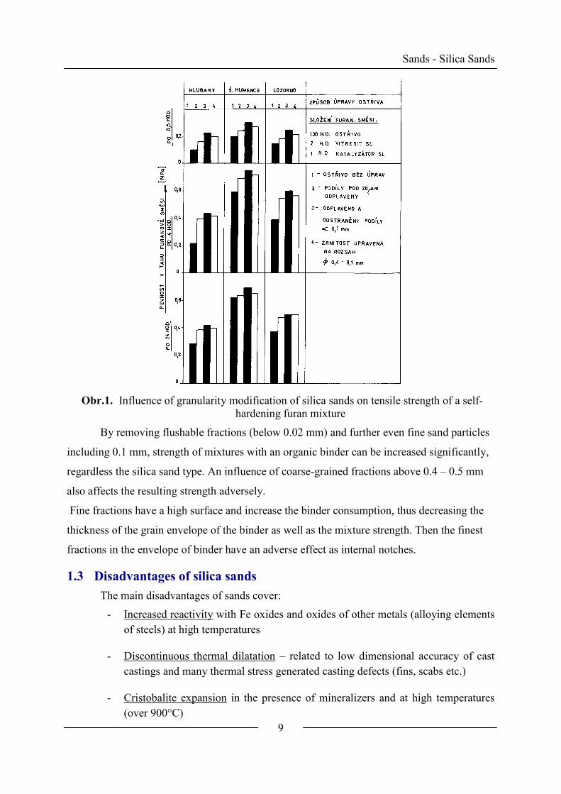
Fig. 1 documents an influence of the above described granulometric processing on
strength of a self-hardening furan mixture for three sorts of silica sands.
Sands - Silica Sands
9
Obr.1. Influence of granularity modification of silica sands on tensile strength of a self-
hardening furan mixture
By removing flushable fractions (below 0.02 mm) and further even fine sand particles
including 0.1 mm, strength of mixtures with an organic binder can be increased significantly,
regardless the silica sand type. An influence of coarse-grained fractions above 0.4 – 0.5 mm
also affects the resulting strength adversely.
Fine fractions have a high surface and increase the binder consumption, thus decreasing the
thickness of the grain envelope of the binder as well as the mixture strength. Then the finest
fractions in the envelope of binder have an adverse effect as internal notches.
1.3 Disadvantages of silica sands
The main disadvantages of sands cover:
- Increased reactivity with Fe oxides and oxides of other metals (alloying elements
of steels) at high temperatures
- Discontinuous thermal dilatation – related to low dimensional accuracy of cast
castings and many thermal stress generated casting defects (fins, scabs etc.)
- Cristobalite expansion in the presence of mineralizers and at high temperatures
(over 900°C)
Sands – Disadvantages of silica sands
10
- Silicosis – a disease caused by silica dust
Considering these main disadvantages, there has been ever increasing effort to replace
silica sands by other minerals (non-silica sands) or by artificial sands.
1.3.1 Increased reactivity of silica sands
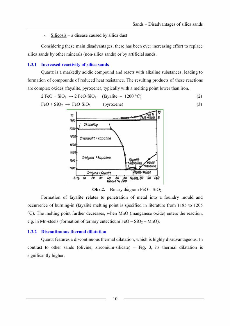
Quartz is a markedly acidic compound and reacts with alkaline substances, leading to
formation of compounds of reduced heat resistance. The resulting products of these reactions
are complex oxides (fayalite, pyroxene), typically with a melting point lower than iron.
2 FeO + SiO2 → 2 FeO·SiO2 (fayalite – 1200 °C) (2)
FeO + SiO2 → FeO·SiO2 (pyroxene) (3)
Obr.2. Binary diagram FeO – SiO2
Formation of fayalite relates to penetration of metal into a foundry mould and
occurrence of burning-in (fayalite melting point is specified in literature from 1185 to 1205
°C). The melting point further decreases, when MnO (manganese oxide) enters the reaction,
e.g. in Mn-steels (formation of ternary eutecticum FeO – SiO2 – MnO).
1.3.2 Discontinuous thermal dilatation
Quartz features a discontinuous thermal dilatation, which is highly disadvantageous. In
contrast to other sands (olivine, zirconium-silicate) – Fig. 3, its thermal dilatation is
significantly higher.
Sands – Disadvantages of silica sands
11
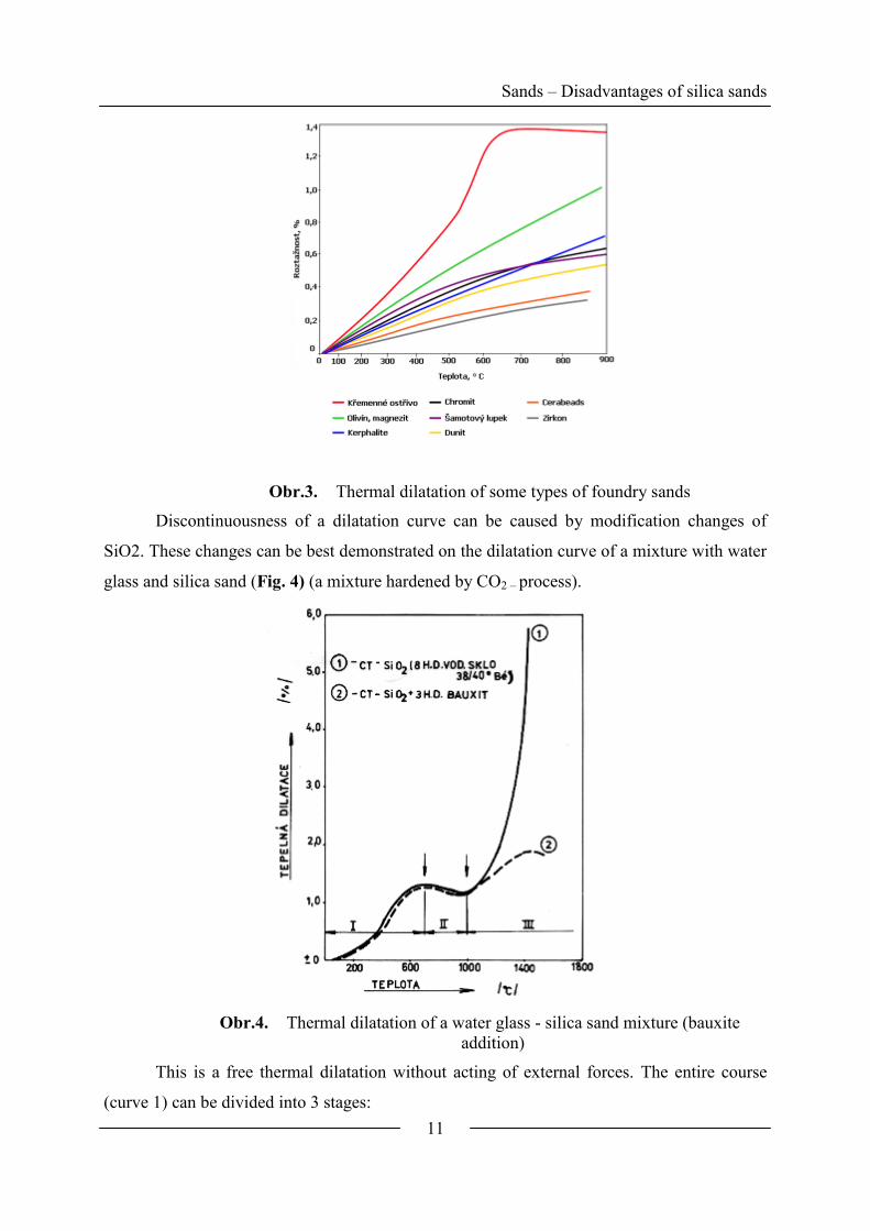
Obr.3. Thermal dilatation of some types of foundry sands
Discontinuousness of a dilatation curve can be caused by modification changes of
SiO2. These changes can be best demonstrated on the dilatation curve of a mixture with water
glass and silica sand (Fig. 4) (a mixture hardened by CO2 – process).
Obr.4. Thermal dilatation of a water glass - silica sand mixture (bauxite
addition)
This is a free thermal dilatation without acting of external forces. The entire course
(curve 1) can be divided into 3 stages:

Sands – Disadvantages of silica sands
12
Stage I: Discontinuous reversible change of the mixture dilatation to 700 °C is caused by
a reversible change of a modification β ↔ α SiO2 (β → α SiO2 573.3 °C; α → β
SiO2 573.1 – 573.2 °C). The specific weight changes only slightly (ρβ-SiO2 =
2650 kg/m3, ρα-SiO2 = 2630 kg/m
3).
The transformation belongs to “rapid
changes” occurring during several seconds. Changes in the crystal lattice are
small. According to the silica sand sort, a linear increase of the mixture reaches
0.86 up to 1.3 %, i.e. c. 2.58 up to 3.9 % of the volume enlargement.
Stage II: Above 700 °C a mild shrinkage of the mixture occurs, which can be explained
both by a slightly negative thermal dilatation coefficient of α – SiO2 and also by
formation of silicic melts, glasses of the binder system (a decrease in strength).
Stage III: At temperatures above 900 - 1000 °C the so-called “slow transformations” occur
– a permanent expansive growth of the mixture, which reaches up to 5% of a
linear dilatation at 1400°C, (c. 15% of the volume dilatation). (Fig. 4)
The discontinuous dilatation process in stage I and its high value result in an
immediate increase in tension from braked free dilatation in a mould. The highest tension
values can be measured in monofraction sands with rounded grains. A high number of casting
defects on casting surfaces result from an increased thermal stress on a foundry mould face.
They cover scabs, fins, sand inclusions and buckles. For instance, the main factors for scabs
are thermal stresses (tensions) generated by the braked mould dilatation and decreased
mechanical properties in a water condensation zone below the mould surface. The most
effective measure to prevent tension generated defects is to replace silica sand by a sand with
a continuous curve with a lower thermal dilatation value (lower tension), without
modification changes. Besides these effects, the reversible change of the dilatation in stage I
is a source of considerable dimensional inaccuracies of castings, too.
1.3.3 Cristobalite expansion
As has been found before, the primary cause of the continuous expansion growth of
mixtures with water glass above 900 – 1000 °C is formation of cristobalite. As substantial
changes in the crystal lattice (hexagonal → cubic) occur during the transition of α – SiO2
into α – cristobalite, this belongs to the so-called “gradual transformation”. Under normal
conditions they are irreversible and their speed depends on the structure, quartz quality and
the presence of catalysts (mineralizers).
However, α – cristobalite cannot be obtained only by heating pure quartz above 900 –
1000 °C, even for as long time as possible, without mineralizers.

Sands – Disadvantages of silica sands
13
Under non-equilibrium conditions in the foundry mould, the transformation of α –
SiO2 into β – cristobalite at 900 – 1000 °C is mineralized (catalyzed) by the presence of
cations (Na – from water glass, K – from resols etc.).
Single-valent cations activate cristobalitization much more intensively, because four-
valent ions Si4+
tend to avoid multivalent cations to penetrate into the lattice.
Some oxides, e.g. Al2O3 (aluminum oxide), in contrast to mineralizers, brake the
quartz transformations and also brake the effect of mineralizers present at the same time.
Then, the process runs very slowly without mineralizers and cristobalite with a highly
defective structure forms.
Fig. 5 shows that e.g. a bauxite addition in collapsed mixtures with water glass
hardened by CO2 (curve 2) prevents the expansion growth.
The cristobalitic expansion was measured experimentally on cuts of testing castings
made through cylindrical cores along their longitudinal axes. A linear expansion of cores
(ymax) in the thermal center of the casting was calculated from the relation:
%100maxmax
ja
yy (4)
where: aj stands for an original diameter of the core
Obr.5. Scheme of measuring of the cristobalitic expansion in cylindrical cores
A real expansion of cores is influenced not only by conditions of the mixture chemical
composition (a content of Na+-ion catalyst, a presence of the silicate melt liquid phase, a sort
and fineness of sand), but particularly by temperature conditions in a core and mainly on the
core-metal interface.
After casting the molten metal into a mould cavity, it solidifies on the surface of the
core, which heats up intensely. When the temperature exceeds 900°C, the cristobalitic

Sands – Disadvantages of silica sands
14
expansion in the core begins, however, this can only develop in dependence on further
process of solidification of the casting outwards from the core. By measuring the temperature
field of cores, it has been found out that the core temperature at a specific ratio of the casting
thermal content to the core thermal content can exceed the solidification temperature of the
primary solidified crust of the casting, which can re-melt and enable further progression of the
expansion until the crust re-solidifies again (periodical solidification) and has such strength
that the core cannot expand anymore, although the cristobalitic expansion in the core volume
goes on. Then, the expansion only results in the tension growth in the core. The core
temperature remains the highest of the whole casting – core system for a long time (a lower
thermal conductivity of the mixture than of the metal) and the core becomes the thermal
centre of the entire casting.
These thermal relations were expressed by a new dimensionless criterion ψ, which
determines a casting/core interaction, and thus also a degree of the core thermal stressing:
jR
R1 (5)
where 1
11S
VR – relative thickness of a casting
V1 – a casting volume representing its thermal content
S1 – a casting surface representing its heat content removal during cooling
Rj – relative thickness of a core
From the thermal point of view, the criterion ψ expresses how much the casting is
larger than the core and what the conditions for the casting solidification and the core heating-
up are.
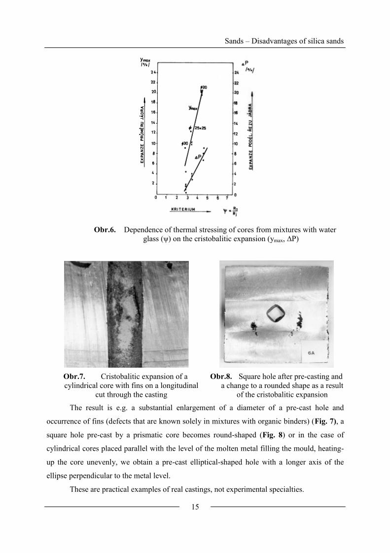
It has been validated experimentally that along with an increasing criterion ψ (thermal
stressing of a core), the cristobalitic expansion value increases, evaluated from the core
diameter change (ymax) and also from the growth of the area of the cross-cut through the core
∆P (Fig. 6).
Sands – Disadvantages of silica sands
15
Obr.6. Dependence of thermal stressing of cores from mixtures with water
glass (ψ) on the cristobalitic expansion (ymax, ∆P)
Obr.7. Cristobalitic expansion of a
cylindrical core with fins on a longitudinal
cut through the casting
Obr.8. Square hole after pre-casting and
a change to a rounded shape as a result
of the cristobalitic expansion
The result is e.g. a substantial enlargement of a diameter of a pre-cast hole and
occurrence of fins (defects that are known solely in mixtures with organic binders) (Fig. 7), a
square hole pre-cast by a prismatic core becomes round-shaped (Fig. 8) or in the case of
cylindrical cores placed parallel with the level of the molten metal filling the mould, heating-
up the core unevenly, we obtain a pre-cast elliptical-shaped hole with a longer axis of the
ellipse perpendicular to the metal level.
These are practical examples of real castings, not experimental specialties.

Sands – Disadvantages of silica sands
16
1.3.3.1 Consequences of the cristobalitic expansion of silica sands
- Dimensional as well as shape accuracy of castings cannot be ensured at higher thermal
stressing of moulds and mainly cores made of pure silica sands in the presence of
mineralizers.
- Burning-in, mainly in steel castings, contain a cristobalite fraction. The cristobalitic
expansion plays an important part in all the mechanism of burning-in formation. The
expanding core tears a layer of a surface protection (coating – surface grease). (Fig. 9)
- Where the speed of metal solidification onto the core surface is high and re-melting of the
crust does not occur (cyclic solidification), i.e. on cores with lower thermal stressing, the
cristobalitic expansion shows itself as a residual stress growth, which influences
collapsibility and cleanability of cores adversely. Therefore the residual strength, measured
on standard-rollers after annealing in a furnace to various temperatures, cannot be above
900 °C a collapsibility rate for mixtures with water glass. The cristobalitic expansion
(residual strength after the maximum II), however, the collapsibility gets further worse
due to the residual stress growth in cores. Cristobalite is a biologically very active
modification of SiO2, therefore it becomes more and more related with an initiation of
silicosis today.
Obr.9. Deformation of cores of silica sand with water glass (CO2– process)
1.4 Non-silica sands
Although non-silica sands are generally more expensive than silica sands and their
price is even integrated with higher powder density (thus a lower volume compared to SiO2),
non-silica sands have been used for the following reasons:
- They have higher heat resistance and thermal stability. This contributes to resistance of
moulds and particularly cores against occurrence of casting defects, above all burning-in.
Mixtures have also better collapsibility after casting as well as recoverability of sand.
- They have a lower and linear thermal dilatation. Castings have a higher dimensional
accuracy and tension generated defects are eliminated (fins).

Sands – Non-silica sands
17
- Moulds and cores have a higher cooling effect. This prevents formation of deep burning-in
and contributes to higher surface and also inner casting quality.
- Their application leads to lower consumption of binders and improvement of hygienic
conditions in foundry shops (silicosis, vasoneurosis).
- They serve for preparation of modern “hybride sands”, improving some drawbacks of
silica sands (dilatation, defects due to tension).
1.4.1 Chamotte
By burning of highly heat resistant schistose clays (schists) in rotary kilns at
temperatures above 1100 °C, burnt shale is obtained – called chamotte schist. In general, this
is a transformation of the kaolinitic clay to a highly heat resistant form of aluminosilicate –
mullite (3 Al2O3 2 SiO2) (melting point 1850 °C).
By milling and screening (with a maximum grain size 3 – 5 mm), sharp-edged
artificial sand can be obtained, which has a continuous dilatation curve (highly resistant
against scabs). It can be applied for binding by kaolinitic clays (chamotte mixtures), water
glass (hardened with CO2) and partly by organic binders (phenolic and alcydic resins). For
foundry purposes more fusible clays are used, where demands for heat resistance are not so
high, but rather for relative density (absorbability below 3 %).
Obr.10. Phase diagram of Al2O3 - SiO2 system (Aramaki and Roy, 1962):
L – liquid, ss – solid solution
Along with an increasing Al2O3 content, or more precisely with decreasing 32
2
OAl
SiO
ratio, chamotte heat resistance increases.
Sands – Non-silica sands
18
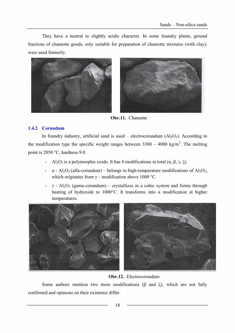
They have a neutral to slightly acidic character. In some foundry plants, ground
fractions of chamotte goods, only suitable for preparation of chamotte mixtures (with clay),
were used formerly.
Obr.11. Chamotte
1.4.2 Corundum
In foundry industry, artificial sand is used – electrocorundum (Al2O3). According to
the modification type the specific weight ranges between 3300 – 4000 kg/m3. The melting
point is 2050 °C, hardness 9.0.
- Al2O3 is a polymorphic oxide. It has 4 modifications in total (α, β, γ, ξ).
- α - Al2O3 (alfa-corundum) – belongs to high-temperature modifications of Al2O3,
which originates from γ – modification above 1000 °C.
- γ - Al2O3 (gama-corundum) – crystallizes in a cubic system and forms through
heating of hydroxide to 1000°C. It transforms into α modification at higher
temperatures.
Obr.12. Electrocorundum
Some authors mention two more modifications (β and ξ), which are not fully
confirmed and opinions on their existence differ.
Sands – Non-silica sands
19
Electrocorundum (α - Al2O3), which is highly indifferent to Fe oxides and stable, is the
most widely used sand.
The electrocorundum is used as sand for preparation of mixtures with clays, water
glass and also with organic binders for special purposes. However, its high price prevents its
more frequent use. Its application as a filler in coatings and surface greases for steel castings
is much more widespread.
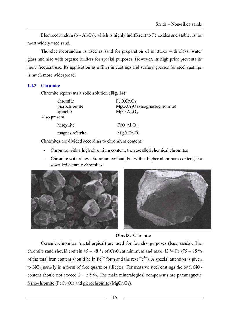
1.4.3 Chromite
Chromite represents a solid solution (Fig. 14):
chromite FeO.Cr2O3
picrochromite MgO.Cr2O3 (magnesiochromite)
spinelle MgO.Al2O3
Also present:
hercynite FeO.Al2O3
magnesioferrite MgO.Fe2O3
Chromites are divided according to chromium content:
- Chromite with a high chromium content, the so-called chemical chromites
- Chromite with a low chromium content, but with a higher aluminum content, the
so-called ceramic chromites
Obr.13. Chromite
Ceramic chromites (metallurgical) are used for foundry purposes (base sands). The
chromite sand should contain 45 – 48 % of Cr2O3 at minimum and max. 12 % Fe (75 – 85 %
of the total iron content should be in Fe2+
form and the rest Fe3+
). A special attention is given
to SiO2, namely in a form of free quartz or silicates. For massive steel castings the total SiO2
content should not exceed 2 ÷ 2.5 %. The main mineralogical components are paramagnetic
ferro-chromite (FeCr2O4) and picrochromite (MgCr2O4).

Sands – Non-silica sands
20
A pH value of chromites ranges between 7 ÷ 8 (10). Along with an increasing
alkalinity, a consumption of acidic catalysts increases (a consumption of an acid for furan
mixtures).
- Density: 4450 – 4650 kg/m3
- Hardness: 5.5
- Volume weight (in relationship to granulometry): 2700 – 2900 kg/m3
Chromite primary grains have a polyhedral shape; they are smooth, black to graphite
coloured. Grains start to melt at 1650°C, the sintering point ranges in interval between 1350 ÷
1450 °C.
Obr.14. Mineralogical components in chromites
Chromite sand is widely used especially in steel casting foundry shops (to prevent
penetration from carbon and alloyed Mn steels) in a combination with furan and phenolic
binders. Due to heat exposure (above 1000 °C) and an oxidation or reducing atmosphere of a
mould (core), crucial mineralogical changes in the chromite sand occur, which can even lead
to an increased tendency of regenerated sands to penetration.
1.4.4 Zirconium-silicate
Zirconium sands represent a mixture of ZrO2.SiO2 and ZrO2. The sand specific weight
is a result of an apportionment of both of the components and ranges from 4560 to 4720
kg/m3. The Mohs hardness is 7.5. Chemical composition of the silicate: 32.8 % SiO2 and
67.2 % ZrO2. The melting point of the silicate is 2100 °C, ZrO2 - 2687 °C, but of sands
approximately 1900 °C.

Sands – Non-silica sands
21
Obr.15. Zirconium-silicate
Compared to silica sands, there are some strong points of zirconium sands:
- Linear thermal dilatation, much lower than in other typical sands
- Twofold thermal conductivity and along with high specific weight a high value of thermal
accumulation coefficient (bf); substantially higher cooling effectivity
- High chemical indifference against Fe oxides at high temperatures resulting in a
considerable resistance to penetration and burning in Preferably used for massive castings
or for a production of highly thermally stressed cores (the zirconium sand is replaced by
chromite due to high price)
SiO2 in zirconium sands is firmly bonded; therefore there is no threat for a silicosis
initiation. Sands can be bound by any binder system. In our conditions, zirconium is only used
for special sand mixtures (high price of the sand), but it is used more often as fillers for
various types of foundry coatings and surface greases. The largest deposits of zirconium sands
are in Australia, Brazil, Senegal, Ceylon and Ukraine.
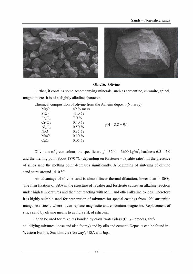
1.4.5 Olivine
Olivine sand is a material of volcanic origin with a high Mg content. In principle, this
is a solid solution of two main silicates.
forsterite Mg2SiO4 (93 %) (melting point = 1900°C)
fayalite Fe2SiO4 (6 %) (melting point = 1205°C)
Sands – Non-silica sands
22
Obr.16. Olivine
Further, it contains some accompanying minerals, such as serpentine, chromite, spinel,
magnetite etc. It is of a slightly alkaline character.
Chemical composition of olivine from the Aaheim deposit (Norway)
MgO 49 % mass
pH = 8.8 ÷ 9.1
SiO2 41.0 %
Fe2O3 7.0 %
Cr2O3 0.40 %
Al2O3 0.50 %
NiO 0.35 %
MnO 0.10 %
CaO 0.05 %
Olivine is of green colour, the specific weight 3200 – 3600 kg/m3, hardness 6.5 – 7.0
and the melting point about 1870 °C (depending on forsterite – fayalite ratio). In the presence
of silica sand the melting point decreases significantly. A beginning of sintering of olivine
sand starts around 1410 °C.
An advantage of olivine sand is almost linear thermal dilatation, lower than in SiO2.
The firm fixation of SiO2 in the structure of fayalite and forsterite causes an alkaline reaction
under high temperatures and then not reacting with MnO and other alkaline oxides. Therefore
it is highly suitable sand for preparation of mixtures for special castings from 12% austenitic
manganese steels, where it can replace magnesite and chromium-magnesite. Replacement of
silica sand by olivine means to avoid a risk of silicosis.
It can be used for mixtures bonded by clays, water glass (CO2 – process, self-
solidifying mixtures, loose and also foamy) and by oils and cement. Deposits can be found in
Western Europe, Scandinavia (Norway), USA and Japan.

Sands – Sieve analysis
23
1.5 Granulometric composition of sands
1.5.1 Cumulative curve of granularity
Properties of a sand mixture depend very much on the granulometric composition of
sand. Results of a sieving analysis are plotted into diagrams, which are a unique
representation of granularity. The most widely used are cumulative curves of granularity (Fig.
17), from which we can read the characteristic criteria of the granulometric composition:
d50 – average granularity (mean size grain), i.e. such a sieve size, through which 50 % of
sand falls down
d25 and d75 – diameters of sieve meshes, to which 25 and 75 % of the total sand weight
corresponds (after flushing away fractions smaller than 0.02 mm)
25
75
d
dS the so-called homogeneity degree (regularity of granularity).
(6)
The sieve analysis is performed using a set of sieves (ČSN ISO 565, a series of
principal sieve sizes R 20/3) with mesh size:
1.0; 0.71; 0.5; 0.355; 0.25; 0.18; 0.063 mm, while the system is vibrating.
Obr.17. Cumulative (integral) curve of the silica sand granularity (0.4 %
flushability)

Sands – Sieve analysis
24
d25= 0.4 mm; d50 = 0.31 mm; d75= 0.25 mm; %5,6210040,0
25,0;
25
75 Sd
dS
The granularity criterion S is satisfying only for natural sands (such as silica sands),
where the cumulative curve in the segment between d25 to d75 has a linear course. The closer
the regularity degree gets to value 1, the more homogeneous the sand is, and vice versa. The
most extreme shapes of the cumulative curve are shown in Fig. 18:
Obr.18. The extreme cumulative curves
In literature we can often meet a classification of sand granularity pursuant to the
American standard AFS (granularity number AFS).A relation of the AFS granularity number
to the average granularity (d50) is shown in Fig. 19.

Sands – Sieve analysis
25
Obr.19. Relationship of the AFS granularity number to the sand average
granularity (d50)
A relation of the number of a sieve (USA) and a mesh size in micrometers is given in
the table below:
Sieve number (USA) Mesh size in micrometers
The rest (20 ÷ 53)
270 Mesh 53
200 75
140 105
100 150
70 210
50 300
40 420
30 600
20 850
12 1700
6 3400
However, this criterion does not assess fractions below d25 and above d75, thus 50 % of
the total mass of the sand. And this assessment is not sufficient at all for artificial sands
(chamotte, schist, alkaline sands, corundum etc.), where the cumulative (integral) curve is
discontinuous, often broken.
Therefore another criterion for assessment of the sand granulometry is implemented –
Log W.

Sands – Sieve analysis
26
1.5.2 Log W criterion
The criterion log W is a thermodynamic function of an arrangement of a system.
According to Planck, the thermodynamic probability (W) is a function of a state and
determines a number of microstates through which the given macrostate is realized.
Boltzmann defines a relation of entropy (S) to W:
S = k·lnW (7)
where k – the Boltzmann constant
AN
Rk ; R – the gas constant; NA – the Avogadro constant
The aforementioned relation implies that the system’s entropy increases along with a
probability of a state and is a criterion of probability. After the mathematical modifications,
equation (7) has a form:
ii NNW log200log (8)
As the logarithm is not defined in zero and 0log0=0, also 1log1=0 and even if the
percentage content is lower than 1, the product NilogNi is negative, then the following rules
are applied for a calculation of log W:
1,10,15,0
5,00
toecirculalizN
calculatednotN
i
i
For the ideal sand, where all grains are of the same size (monofraction), log W is zero,
i.e. log W = 200-100log100=0.
For real sand the value log W ranges between the limits:
RW log0 (9)
Where R is a positive integer number, which is defined by a number of sieves on
which the granulometric analysis is performed. For the sieving analysis according to ČSN
721531, 7 sieves are used and one “sub-sieve“ (a dish for the rest of the fraction 0.020-0.060
mm); the threshold log W value is defined in the following way:
309,908log1008
100log
8
1008200log
%8
100
W
N i
(10)
The closer log W gets to 0, the more grains are concentrated in one fraction; the closer
to 90.31, the more evenly in 8 fractions.
Sands – Sieve analysis
27
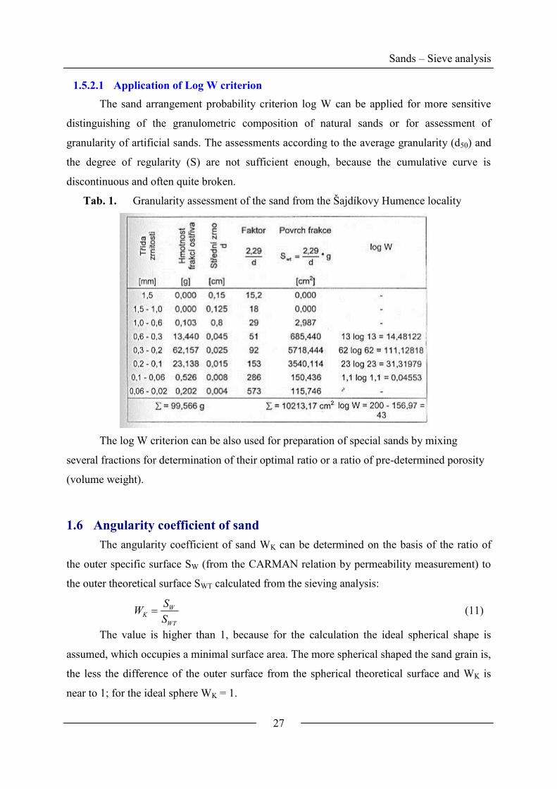
1.5.2.1 Application of Log W criterion
The sand arrangement probability criterion log W can be applied for more sensitive
distinguishing of the granulometric composition of natural sands or for assessment of
granularity of artificial sands. The assessments according to the average granularity (d50) and
the degree of regularity (S) are not sufficient enough, because the cumulative curve is
discontinuous and often quite broken.
Tab. 1. Granularity assessment of the sand from the Šajdíkovy Humence locality
The log W criterion can be also used for preparation of special sands by mixing
several fractions for determination of their optimal ratio or a ratio of pre-determined porosity
(volume weight).
1.6 Angularity coefficient of sand
The angularity coefficient of sand WK can be determined on the basis of the ratio of
the outer specific surface SW (from the CARMAN relation by permeability measurement) to
the outer theoretical surface SWT calculated from the sieving analysis:
WT
WK
S
SW (11)
The value is higher than 1, because for the calculation the ideal spherical shape is
assumed, which occupies a minimal surface area. The more spherical shaped the sand grain is,
the less the difference of the outer surface from the spherical theoretical surface and WK is
near to 1; for the ideal sphere WK = 1.

Sands – Angularity coefficient
28
Drift sands are nearest to the ideal sphere shape. The shape differs from the ideal
spherical grain only by 8 – 16 %. Their deposits (localities) are of allochthonous origin, i.e.
they did not originate in the extraction location, but they were transported by wind or water
from far away distances, transported grains knocked against each other and therefore their
shapes became rounded by abrasion. On the contrary, sands from autochthonous deposits are
more angular, e.g. those obtained from kaolin washing differ from the ideal spherical shape
by 12- 52 %. Sands prepared artificially by grinding of refractory materials, such as
chromium-magnesite, electrocorundum, chamotte etc. have a substantially higher angularity
than the above mentioned sands (WK>2.0).
Angularity is of considerable technological importance. Higher angularity of sand
leads to lower compactibility of a mixture (lower volume weight) with all the consequences
for strength, permeability, penetrability and thermal tensions during heating. Angular sands
cannot be combined with organic binders (oils, resins) effectively, because grain envelopes
become ruptured on edges and in corners (loss of compactness), further leading to
inadequately high binder consumption with all the consequences, such as high price of the
mixture etc.
Chromite sand Olivine sand Zirconium sand (zirconium-
silicate)
Obr.20. Different angularity of natural sands (25x magnification)
The different angularity of natural sands is evident in Fig. 20. Grains can be divided
according to the shape (AFS):
- angular
- semiangular
- rounded
- combined
Some authors divide angular grains to:

Sands – Angularity coefficient
29
- angular with rounded edges
- sharp-edged
- splintery
Along with grain fineness, their angularity increases (natural sands), Fig. 21:
Obr.21. Relation of grain angularity to their size
The more rounded grains, the higher compactibility of clay mixtures (Fig. 22).
Obr.22. Grain shape influence on compactibility of a mixture
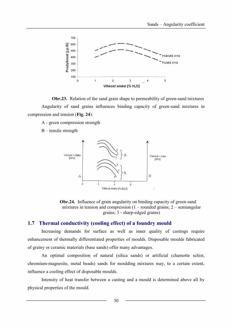
Permeability of green-sand mixtures also depends on the base sand angularity (Fig.
23):
Sands – Angularity coefficient
30
Obr.23. Relation of the sand grain shape to permeability of green-sand mixtures
Angularity of sand grains influences binding capacity of green-sand mixtures in
compression and tension (Fig. 24):
A - green compression strength
B – tensile strength
Obr.24. Influence of grain angularity on binding capacity of green-sand
mixtures in tension and compression (1 – rounded grains; 2 – semiangular
grains; 3 - sharp-edged grains)
1.7 Thermal conductivity (cooling effect) of a foundry mould
Increasing demands for surface as well as inner quality of castings require
enhancement of thermally differentiated properties of moulds. Disposable moulds fabricated
of grainy or ceramic materials (base sands) offer many advantages.
An optimal composition of natural (silica sands) or artificial (chamotte schist,
chromium-magnesite, metal beads) sands for moulding mixtures may, to a certain extent,
influence a cooling effect of disposable moulds.
Intensity of heat transfer between a casting and a mould is determined above all by
physical properties of the mould.
Sand – cooling effect
31
Coefficient of thermal conductivity 11 KmW
Specific heat 11 KkgJc
Volume weight 3mkgV
Heat transfer in a foundry mould is affected by:
a. Heat conduction (thermal conductivity)
b. Heat emission (heat radiation)
c. Heat convection (heat flow)
The thermal conductivity in the porous disperse material is realized above all through
places of contacts of individual sand grains. Theoretically, in the ideal base sand, this is a
point contact of spheres, however, in real mixtures, considering the grain angularity, the
presence of binder bridges, water and additives, there are areas of contact increasing the total
conductivity.
Pure quartz (ρ = 2650 kg/m3) has 112,7 KmW , while e.g. a bentonite mixture
(ρv = 1500 kg/m3) has 1133,0 KmW , which is a value 22-fold lower. By addition of 10
% of H2O (ρ v= 1650 kg/m3), λ increases to 1113,1 KmW , i.e. 3.46-times. A clay
addition increases 3-times at minimum.
Therefore castings have a shorter solidification time e.g. in green-sand moulds. Air
and gas in intergrain spaces also shares the heat transfer, however, they have λ approximately
an order of magnitude lower than sand, therefore they need not to be taken into account for
the conduction heat transfer. However, heat transfer does not occur only by conduction, but
simultaneously by convection, and at higher temperatures also by radiation, therefore with
much higher intensity.
From this point of view there are many possibilities to regulate λ in real moulds and
cores, especially through granulometry control, sand type selection and densification degree
(volume weight).
Along with an increased densification degree of a mould the volume weight of the
mould (v) increases, porosity (λ) decreases and thermal conductivity increases (Fig. 25):
%100
2
2
SiO
VSiOm
(11)
where: SiO2 – sand specific weight (SiO2)

Sand – cooling effect
32
Obr.25. Relation of thermal conductivity to porosity of mixtures according to
experimental measurements by various authors
An influence of the densification degree on λ = f(t) is demonstrated for a mixture with
water glass (CO2 – process) of a composition:100 weight parts. Silica sand, Provodín 036
d50 = 0.35 mm, S = 0.52, log W = 55.5, 1209,7 kgmSWT
water glass 5 weight parts, 50°Bé (m = 2.4)
A known fact has been validated that along with the increasing densification degree (ρ
v= 1500, 1650 and 1800 kg/m-3
) the thermal conductivity in the entire interval of the observed
temperatures (to 800 °C) increases (Fig. 26).
Obr.26. Relation of thermal conductivity to temperature in mixtures with water
glass (CO2) at different volume weight

Sand – cooling effect
33
1.7.1 Cooling effect of non-silica base sands
Cooling effect of moulds with non-silica sands can be evaluated above all through the
heat absorbing capacity coefficient (bf).
ffff cb [Ws0,5
m-2
K-1
] (12)
where: f - thermal conductivity coefficient
cf – specific heat
f – volume weight
bf can be defined as heat amount accumulated (absorbed) by a mould (s
JW ;
watt = amount of heat, J – joule per 1 second) on a mould – metal unit area (m2),
whereas the mould is heated by 1 °C (K).
Besides the base sand type, the sort and amount of a binder plays also an important
part (the content of free water, green-sand mixture), however, the decisive factor remains the
base sand type. The higher bf, the faster metal on the mould (core) solidifies and the lower
possibility for the molten metal to penetrate into intergrain spaces (higher resistance of the
mould against penetration - burning-in).
Tab. 2. Cooling effect of selected sands (according to Halbart)
Heat absorbing capacity coefficient
(according to G.Halbart)
Composition of a mould bf[W. s0,5
.m-2
.K-1
] [%]
1 – magnesite 3510 100
6 - chromite 2765 78.8
4 - chromite 2391 68.1
8 - chromite 2319 66.0
5 - chromite
olivine
1930 55.0
3 - olivine 1821 51.9
2 - dunite 1734 49.4
7 - kerphalite 1665 47.4
Magnesite and chromite give the highest cooling effect to mixtures (mould). Dunite
and kerphalite sands reach approximately half the value.For the comparison, there is a mixture
with silica sand (water-glass 6.4 %): bf = 1550 Ws0,5
m-2
K-1
.
Reclamation
34
2 Reclamation of moulding sand mixtures
Generally the term ‘regeneration (reclamation) of moulding sand mixtures’ means an
obtaining of a substantial part of sand from the used sand mixture back for preparation of new
pattern and core mixtures. Reclamation of sand comprises a series of procedures necessary to
bring the sand into a condition applicable for the re-use.
What are the principal reasons for reclamation?
A Economic Prices of high quality sands increase, especially after special
treatment (drying, sorting of monofractions and composing the
demanded granulometry, activation).
Total cost for 1 t of a reclaim should be more economically
profitable than for 1 t of new base sand (price for depositing
waste sands).
B Transport and
handling
Costs for transportation of sands are a considerable portion of
the total price. High cost relates to transportation of used sands
to dumps. Next to these influences, there is also a favourable
influence of higher self-sustainability of foundries in raw
materials, especially in winter season there is no need to build
such large waste spaces for sand pre-supply.
C Limitation of
localities with new
sands
It is not possible to extract wherever even rich deposits of high
quality sands are located.
D Utilization of sands
for other industrial
branches
Glass-making and building industry.
E Environment
protection
This relates to C article. Exportation of used mixtures (hazardous
waste) has been strictly limited and closely watched recently.
Mixtures contain also many pollutants from binders and
additives (phenol, Na2CO3, ammonia salts and other chemicals),
which are washed off and pollute subsoil waters, river courses
etc.
F Technological A reclaim has a lower absorbability of an organic binder while
reaching the same mechanical properties of moulds and cores. A
decrease in binder consumption closely relates to a reduction of
gas-making ability of mixtures. Mixtures with a regenerate are
even less susceptible to occurrence of defects generated by
tension in a foundry mould due to braked thermal dilatation –
scabs, fins. Grain surface gets rounded and processed. This
means that through an effective reclamation, properties of new
less quality sands can be even improved to a certain extent.

Reclamation
35
A sand grain from a used mixture is enveloped by a layer of a binder, which,
according to a degree of thermal decomposition (distance from a casting), is either in its
original condition (polycondensed resin, silicic acid gel with other products of a hardening
reaction, dried clay paste) or in a condition of destruction / complete destruction (coke
residues from organic binders, silica glass, oolitization layer of clay). According to the used
binder type in a mixture, and adhesive (adherent) forces of a layer to the sand surface, we
must use various effective devices and procedures to obtain a grain surface as clean as
possible. Some hardening reaction products, harmful for next use of the reclaim, are even
soluble in water. The reclamation through water can be used preferably.
Obr.27. Flowchart of regeneration procedures
All types of mixtures cannot be treated by conventional reclamation procedures, so
that 100 % are usable for the new demanding manufacture of moulds and cores. This fact
leads to a need to use only a specific part of a reclaim for preparation of a new mixture or to
proceed to further combined regeneration procedures and to extend the reclamation process
extremely.
Anyway, the sand reclamation requires a construction of a complex system for mixture
grinding, removing metal particles, cooling, drying, screening, exhausting fine fractions and
other special processing in accordance with an actual procedure and equipment.
Combinations of basic procedures are frequently used (Fig. 27).
3 Strength of moulding mixtures
Next to base sand, a binder is the main component of a sand mixture. The sand –
binder interaction generally shows itself in strength of moulding mixtures.
Strength of molding mixtures
36
Binding capacity – strength in a mixture in green condition after densification, which
is decisive for fluidity, compactibility, formability of the mixture and other technological
properties at forming
Strength – after drying (skin drying, burning or hardening), which is the initial
strength in a molten metal contact with a mould (core)
Strength at elevated and high temperatures – decisive for plasticity of a mould
(value of exogenous stresses in castings) and a number of casting defects (cracks, swells).
Strength in the water condensation zone at 100°C temperature belongs here, too.
Residual strength – affects collapsibility of moulds and cores, and thus also
cleanability of castings
The long-time and perspective development of binder systems, and also of sand
mixtures, can be divided into four generations:
Ist generation mixtures – binding is a result of capillary binding forces and van der
Waals forces (sand mixtures with clay binders)
IInd generation mixtures – using chemicals for the process of sand mixture binding
(mixtures with inorganic binders, e.g. water glass) and with organic binders (mixtures with
artificial resins, saccharides and oils)
IIIrd generation mixtures – using physical effects of e.g. force fields for binding
(magnetic mould), vacuum (V-method) and also frozen water – ice (EFF- SET process). This
covers also binderless systems with a gasified pattern (a full-mould process, REPLICAST,
LITGAZ, LOST FOAM).
IVth generation mixtures – where biological procedures are used for binding
(biotechnology)
The oldest Ist generation mixtures (clay binder mixtures) are still used for the
manufacture of moulds (unified bentonite mixtures) and cores for massive steel castings
(chamotte mixtures) and we can see ever increasing interest in application of physical
processes for base sand binding, above all force fields (electric, magnetic), vacuum, crystal
binding with ice etc., which is motivated by an effort for transition to wasteless foundry
technologies.
An objective evaluation of binding properties of binders should be performed for
standard sand (silica sand FRECHEN-BRD, the world standard) according to the reached
specific tensile strength (kPa/1%) and collapsibility after casting, the effectiveness in
Strength of molding mixtures
37
accordance with economic criteria, above all the cost needed to obtain tensile strength of 1
kPa (CZK/1kPa).
3.1 Strength of moulding sand mixtures as a result of adhesion –
cohesion forces of a binder
Strength of a mixture is a result of the binder - base sand interaction. From the point of
view of adhesion – cohesion forces of foundry binders, mixture destruction may be of
following three characters:
Cohesion – cohesion forces of a binder (forces of interaction between homogeneous
atoms – molecules) (designation K) are smaller than adhesion forces between the binder and
the sand (interphase forces between atoms – molecules in surface layers) (designation A); A
>> K.
Adhesion – cohesion – a combination of A÷K
Adhesion A << K
Cohesion work is defined as a total work needed to overcome cohesion forces of the
given material. It is proportional to the energy needed to put a molecule from the liquid or
solid state off to very distant position. It approximately equals evaporation heat.
Adhesion is a comprehensive expression for all factors causing adhesion of two
matters one to another. It originates by effect of chemical, physical and mechanical forces
occurring in molecular distances.
The important adhesion affecting factor is good wetting of the solid phase by a binder.
The work needed for breaking the interphase boundary is called adhesion work (Aadh) and it
can be expressed by the Dupré equation:
adhA l g s g s l (13)
.(l-g) [Pa] The equilibrium surface stress between the liquid and gaseous
matter,
.(s-g) [Pa] The equilibrium surface stress between the solid matter and their
vapours
.(s-l) [Pa] The surface stress between the solid and liquid matter
The work of adhesion can be also expressed using the contact angle (wetting angle)
(cos):
adhA l g 1 cos (14)
Binders of the 1st generation
4 Binders the Ist generation
4.1 Clay binders
Clay binders still belong to the most widespread foundry binders. About 70 % of all the
world’s production of castings are manufactured into moulds of bentonite mixtures*. They are
contained in natural sands and used in a pure condition for binding of washed sands, sometimes
of artificial base sands. They have excellent technological and hygienic properties, they are cost-
effective, have a satisfactory binding capacity, strength after drying, re-usability, they determine
a non–demanding preparation of mixtures and their depositing, e.g. without carbon additions,
and usually do not cause ecological problems.
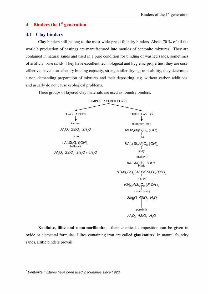
Three groups of layered clay materials are used as foundry binders:
Kaolinite, illite and montmorillonite – their chemical composition can be given in
oxide or elemental formulas. Illites containing iron are called glaukonites. In natural foundry
sands, illitic binders prevail.
* Bentonite mixtures have been used in foundries since 1920.
SIMPLE LAYERED CLAYS
TWO LAYERS THREE LAYERS
kaolinit
2 3 2 2Al O 2SiO 2H O
nebo
2 2 5 4Al Si O OH
halloysit
2 3 2 2 2Al O 2SiO 2H O 4H O
illit
4 7 20 4KAl Si Al O OH
slídy
muskovit
2 3 10 2KAl AlSi O OH
biotit
3 103 2K Mg,Fe Al,Fe Si O OH
flogopit
3 3 10 2KMg AlSi O F,OH
montmorillonit
3 8 20 4NaAl MgSi O OH
mastek (talek)
2 23MgO 4SiO H O
pyrofylit
2 3 2 2Al O 4SiO H O

Binders of the 1st generation
When a content of montmorillonite is higher than 7580 %, these clays are called
bentonites. They are the most widely used clay binders allowing “green-sand moulding” into
bentonite mixtures.
In kaolinitic clays, the main component is kaolinite. These refractory clays also serve as
binders for preparation of chamotte mixtures.
4.2 Water in clay minerals
A water molecule has a polar character (r = 0.138 nm) with properties of a dipole (with a
dipole moment = 1.84 of Debye units). The dipole character allows a mutual association.
Through hydrogen bonding, chains with a planar to spatial orientation of polymers are formed
(Fig. 28).
1,01 A
105°
0
1,32 A
0,90 A
0
.H
.
H
H H
PLOŠNÁ ASOCIACE MOLEKUL VODY
.
Obr.28. Dipoles of water molecules and their planar association
A number of hydrogen bonds per one molecule depend on state of matter of water
(temperature and pressure).
neboH
HH OH
OHHOH
HOH
There are four hydrogen bonds per one molecule in ice, and 2 to 3 in liquid at 0°C. It can
be assumed that vapour contains only monomers and at a gradual increase of pressure more and
more polymer molecules form, so normal water does not contain monomer molecules. A
structure of ice is well known, however, a structure of liquid water has not been fully cleared up.
In principle, water in clay materials is of two types:
In 1847 a name „montmorillonite“ was created for this mineral in France. In 1898 an American geologist
KNIGHT called the extracted clay with montmorillonite content „bentonite“ according to the Fort Benton in American Montana.

Binders of the 1st generation
Molecular water (represents approximately 10% of the mineral mass). It occurs in
interlayer spaces (intracrystalline swelling) or adsorbed on the surface of packets
(intercrystalline swelling) and in pores between packets of particles.
Lattice water - hydroxyl (OH-), as a part of the crystal lattice
Dehydration cannot be performed quantitatively to temperature of 110°C. Complete
evaporation of molecular water occurs no sooner that at 250300°C temperature. The process is
perfectly reversible. Therefore attention should be paid to selection of optimal temperature for
drying of bentonite mixtures for determination of moisture.
In accordance with a content of molecular (free) water in clay mixtures, clay mixtures
can be divided to several types intended for various mould making technologies:
max. content of 0.2 %: Anhydrous mixtures (clay is swelled by other organic matters –
organobentonites)
1.62.5 %: Semi-dry mixtures (for compressing by higher specific compacting pressures
and other technologies requiring high compactibility of a mixture)
max. content of 5 %: Green-sand
67 %: For skin-drying (skin-drying, short-time drying) for instance a mould face by hot
air and casting after a short time (water return transport)
above 67 %: For drying and burning. Chamotte mixtures with high-temperature drying
for removing also chemically bound water (temperature dehydroxylation)
4.3 Bentonite and bentonite mixtures
In literature, various forms of chemical, oxidic and elemental formulas of
montmorillonites are presented, such as:
2 4 10 22E Al Si O OH nH O (15)
2 3 2 2 2Al O 4SiO H O nH O (16)
2 2E Na ,K ,Ca ,Mg
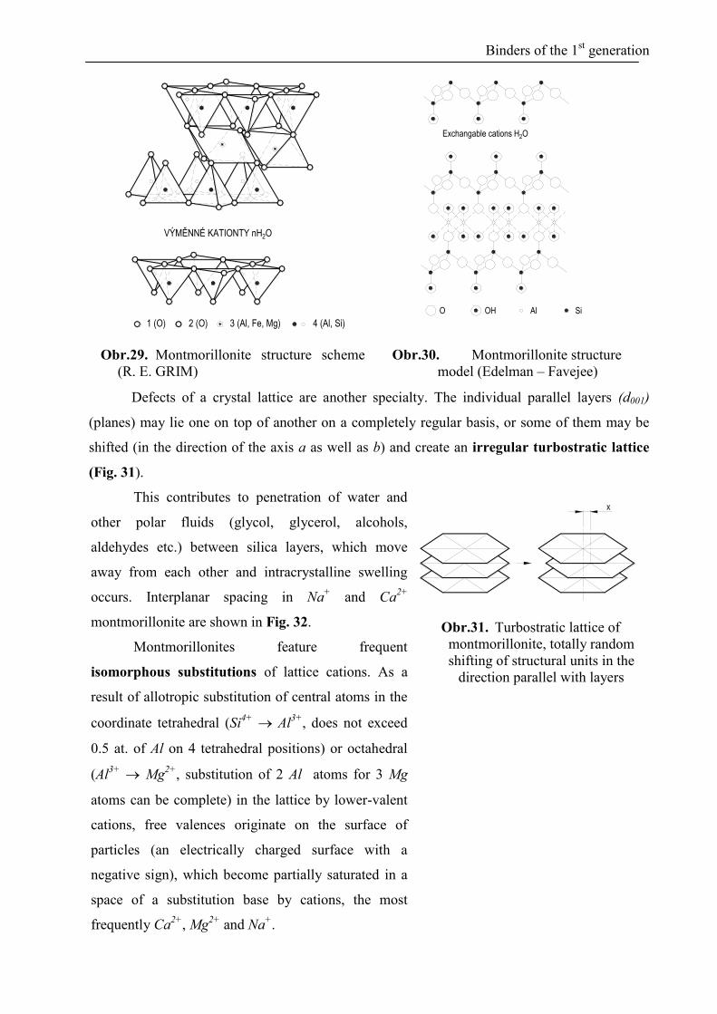
Montmorillonites have a typical three-layer structure (in contrast to e.g. 2-layer
kaolinites). A gibbsite octahedral (AlO6)-is between two silica tetrahedrals (SiO4)
4- (Fig. 29 and
30). In octahedrals and tetrahedrals, atoms are bonded by relatively fixed covalent bonds.
Individual layers are bound by weak van der Waals forces. Structural construction is based on
layers 2:1.
Binders of the 1st generation
1 (O) 2 (O) 3 (Al, Fe, Mg) 4 (Al, Si)
VÝMĚNNÉ KATIONTY nH2O
O OH Al Si
Exchangable cations H2O
Obr.29. Montmorillonite structure scheme
(R. E. GRIM)
Obr.30. Montmorillonite structure
model (Edelman – Favejee)
Defects of a crystal lattice are another specialty. The individual parallel layers (d001)
(planes) may lie one on top of another on a completely regular basis, or some of them may be
shifted (in the direction of the axis a as well as b) and create an irregular turbostratic lattice
(Fig. 31).
This contributes to penetration of water and
other polar fluids (glycol, glycerol, alcohols,
aldehydes etc.) between silica layers, which move
away from each other and intracrystalline swelling
occurs. Interplanar spacing in Na+ and Ca
2+
montmorillonite are shown in Fig. 32.
Montmorillonites feature frequent
isomorphous substitutions of lattice cations. As a
result of allotropic substitution of central atoms in the
coordinate tetrahedral (Si4+
Al3+
, does not exceed
0.5 at. of Al on 4 tetrahedral positions) or octahedral
(Al3+
Mg2+
, substitution of 2 Al atoms for 3 Mg
atoms can be complete) in the lattice by lower-valent
cations, free valences originate on the surface of
particles (an electrically charged surface with a
negative sign), which become partially saturated in a
space of a substitution base by cations, the most
frequently Ca2+
, Mg2+
and Na+.
A - PRAVIDELNÁ B - NEPRAVIDELNÁ
TURBOSTATICKÁ
Obr.31. Turbostratic lattice of
montmorillonite, totally random
shifting of structural units in the
direction parallel with layers
Binders of the 1st generation
Therefore the montmorillonite surface has a negative charge (O2-
). This structural effect
is a cause of an extraordinary sorption capacity of montmorillonite. When compensating the
negative charge, cations are bound between particles by different forces, enabling to set a
system of ion exchange capacity (16):
2 2 2 2Li Na H K Mg Ba ,Ca ,Sr Rb (16)
We can perform a substitution of Ca2+
- Mg
2+ ions by Na
+, which is technologically
considerably advantageous in bentonite mixtures. This process is called natrification.
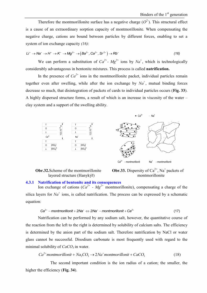
In the presence of Ca2+
ions in the montmorillonite packet, individual particles remain
together even after swelling, while after the ion exchange by Na+, mutual binding forces
decrease so much, that disintegration of packets of cards to individual particles occurs (Fig. 33).
A highly dispersed structure forms, a result of which is an increase in viscosity of the water –
clay system and a support of the swelling ability.
O
Ca2+
O
T
[AlO6]-
[SiO4]4-
15,5
.10-1
0
12,5
.10-1
0
Na+
[SiO4]4-
[AlO6]-
O
T
O
m m
T T
Ca2+ Na+
Ca2+ - montmorillonit - montmorillonitNa+
Obr.32. Scheme of the montmorillonite
layered structure (Hanykýř)
Obr.33. Dispersity of Ca2+
, Na+
packets of
montmorillonite
4.3.1 Natrification of bentonite and its consequences
Ion exchange of cations (Ca2+
- Mg2+
montmorillonite), compensating a charge of the
silica layers for Na+ ions, is called natrification. The process can be expressed by a schematic
equation:
2 2Ca montmorillonit 2Na 2Na montmorillonit Ca (17)
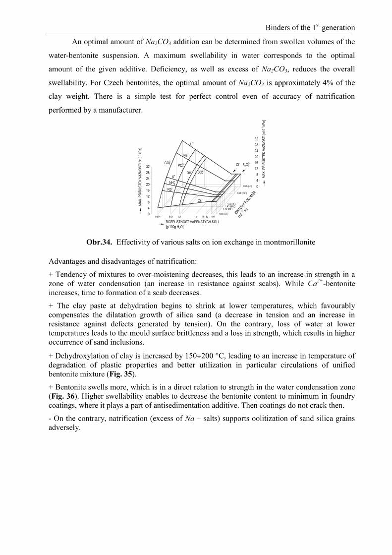
Natrification can be performed by any sodium salt, however, the quantitative course of
the reaction from the left to the right is determined by solubility of calcium salts. The efficiency
is determined by the anion part of the sodium salt. Therefore natrification by NaCl or water
glass cannot be successful. Disodium carbonate is most frequently used with regard to the
minimal solubility of CaCO3 in water.
332
2 2 CaCOonitmontmorillNaCONaonitmontmorillCa (18)
The second important condition is the ion radius of a cation; the smaller, the
higher the efficiency (Fig. 34).
Binders of the 1st generation
An optimal amount of Na2CO3 addition can be determined from swollen volumes of the
water-bentonite suspension. A maximum swellability in water corresponds to the optimal
amount of the given additive. Deficiency, as well as excess of Na2CO3, reduces the overall
swellability. For Czech bentonites, the optimal amount of Na2CO3 is approximately 4% of the
clay weight. There is a simple test for perfect control even of accuracy of natrification
performed by a manufacturer.
0,001 0,01 0,1 30 1001,0
ROZPUSTNOST VÁPENATÝCH SOLÍ
[g/100g H2O]
MA
X. P
ŘÍR
ŮS
TE
K V
AZ
NO
ST
I [x1
0-1 k
Pa]
0
4
8
12
16
20
24
28
32
101,65 (Cs+)
1,49 (Rb+)1,43 (NH+
4)1,33 (K+)
0,98 (Na+)
0,78 (Li+) 0
4
8
12
16
20
24
28
32
MA
X. P
ŘÍR
ŮS
TE
K V
AZ
NO
ST
I [x1
0-1 k
Pa]
IONTO
VÝ PO
LOM
ĚR
[10
-10 m
]
Cs+
Rb+
NH+4
K+
Na+
Li+
CO2-3 PO3-
4
OH- SO2-4
S2O2-3Cl-
Obr.34. Effectivity of various salts on ion exchange in montmorillonite
Advantages and disadvantages of natrification:
+ Tendency of mixtures to over-moistening decreases, this leads to an increase in strength in a
zone of water condensation (an increase in resistance against scabs). While Ca2+
-bentonite
increases, time to formation of a scab decreases.
+ The clay paste at dehydration begins to shrink at lower temperatures, which favourably
compensates the dilatation growth of silica sand (a decrease in tension and an increase in
resistance against defects generated by tension). On the contrary, loss of water at lower
temperatures leads to the mould surface brittleness and a loss in strength, which results in higher
occurrence of sand inclusions.
+ Dehydroxylation of clay is increased by 150200 °C, leading to an increase in temperature of
degradation of plastic properties and better utilization in particular circulations of unified
bentonite mixture (Fig. 35).
+ Bentonite swells more, which is in a direct relation to strength in the water condensation zone
(Fig. 36). Higher swellability enables to decrease the bentonite content to minimum in foundry
coatings, where it plays a part of antisedimentation additive. Then coatings do not crack then.
- On the contrary, natrification (excess of Na – salts) supports oolitization of sand silica grains
adversely.

Binders of the 1st generation
PE
VN
OS
T V
KO
ND
EN
ZA
ČN
Í ZÓ
NĚ
[kP
a]0
0,5
1,0
1,5
2,0
Na+
Ca2+
0 200 400 600 800
TEPLOTA ŽÍHÁNÍ BENTONITU [°C]
Obr.35. Influence of bentonite annealing temperature on strength in the water
condensation zone (Na+ - Ca
2+ bentonite)
0 2 4 6 8 10 12 14 16 18 20
OBJEM PO NABOBTNÁNÍ [ml]
PE
VN
OS
T V
KO
ND
EN
ZA
ČN
Í ZÓ
NĚ
[kP
a]
0,4
0,8
1,2
1,6
2,0
2,4
Obr.36. Relationship of strength in the water condensation zone to the
bentonite swellability
4.4 Additives for bentonite mixtures
Carbohydrates (saccharides, pentosans, cellulose)
Wood powder, lignin
Oxidants
Graphite
Lustrous carbon carriers (theory of lustrous carbon)
The above mentioned additives for unified bentonite mixtures (UBM) have different
functions. On the one hand, they have to decrease compactibility and increase strength in the
water condensation zone, thus increasing resistance to tension generated defects (scabs), to
increase permeability, to decrease friability and the mould face drying-off, to increase
toughness of a mixture (improvement of liftability of patterns from moulds), to improve
collapsibility (to prevent formation of lumps) and on the other hand, to enhance surface quality

Binders of the 1st generation
of castings of graphitizing iron alloys (penetration, roughness of a casting) or to reduce
dangerous exhalations during casting.
The water-bentonite binder system can be only supported by additives developing their
binding abilities in water environment during mixing, not hardening, thus supporting reversible
properties during each circulation of the UBM - unified bentonite mixture. The lower water
content in bentonite, the higher strength of bentonite, but also the higher brittleness. Along with
increasing strength of a mould (hardness), a risk of explosive penetration increases.
4.4.1 Saccharides
In foundry industry, the most frequently used saccharides are monosaccharides
(pentoses, hexoses), oligosaccharides (saccharose) and polysaccharides (starches, dextrins,
cellulose). Starches feature dissolubility under cold condition, however, they have an ability to
take in water at higher temperatures, thus reducing inclination to formation of scabs.
Therefore cold-soluble forms of starches have been developed (cold starches). These
cause a noticeable enhancement of properties in bentonite mixtures, improving lifting-out
patterns from moulds (toughness), decreasing erosion and wear. Cold solubility can be improved
by shortening saccharide chains, which are more water-soluble (starch milling). Thus their effect
in UBM is markedly improved (this is the effect of dextrins and pyrodextrins – starches with
shortened chains).
4.4.2 Oxidants
Using a new technology, through oxidation additives the properties of bentonite mixtures
improve and exhalation volume is reduced at the same time. A mixture of water with ozone (10
ppm in water) and hydrogen peroxide is subjected to ultrasound treatment. An additive prepared
this way (treated water) contains relatively stable radicals, which are able to react with bentonite
and at the same time activate carbon (lustrous carbon carriers), which reduces emissions of
aromas, above all benzene (drop by as much as 74%). The treated water increases binding
capacity of mixtures, which allows reduction of bentonite content in unified bentonite mixtures
as well.
4.4.3 Graphite
Hexagonal layered structure of graphite with glide properties, high anisotropy, water
repellence and also heat resistance, contributes to good fluidity of a mixture even at low
moisture. Through incorporating graphite into bentonite (layered montmorillonite), its faster
intracrystalline swelling occurs. Up to 5 mass % of graphite addition for bentonite is used. Its
presence reduces occurrence of burning-on. An optimal moisture in a mixture decreases (by
0.20.3%) even at an increasing content of flushable substances in UBM. A decrease in water
Binders of the 1st generation
demand leads to lower oxidation of carriers of lustrous carbon. Uniform densification of a
mould and reduction of the free water content leads to limiting the occurrence of “explosive
penetration”. Compacting (pressing) pressures on forming equipment can be decreased. The
presence of the so-called “process carbon” shows itself above all by an increase in strength of a
mixture in the water condensation zone.
4.4.4 Carriers of lustrous carbon
Graphitizing iron alloys (grey iron – LLG and ductile iron – LKG) are typical alloys with
high fluidity. They closely outline contours of the foundry mould and easily penetrate into
intergrain spaces. If the metal penetration depth is less than an average sand size (d50), grains
can be easily removed from the casting surface and only roughening of a casting shell occurs.
The surface smoothness of castings cast into bentonite mixture moulds is a result of the metal-
mould interaction and the following cleaning method (blasting). Therefore a worldwide
attention has been paid to carbonaceous additives (C-additives) to green-sand mixtures, both
from the point of view of their efficiency for formation of a surface, and also ecological impacts
on working and living environment (depositing waste sands on storage grounds).
Theory of a complex effect of a carbonaceous additive C-additive in mixture exhibits
versatile effects:
Formation of lustrous carbon - LC (surface smoothness)
At the same time, formation of coke (semi-coke), compensating thermal micro-dilatations
of quartz grains (tension generated casting defects), and clogging of intergrain spaces
(penetration prevention)
Formation of gaseous components (volatile fractions) disintegrating bentonite mixture
lumps, thus improving collapsibility of moulds
According to I. Bindernagel retort test, C-additive with complex effects should have the
following composition:
LC (1119)%
Coke residue (4358)%
Volatile substances (2738)%
Determination of lustrous carbon (I.Bindernagel’s retort test)
The International Committee of Foundry Technical Association (C.I.A.T.F.), led by I.
Bindernagel, has worked out a retort test for determination of LC in C-additives. This test has
become a subject in national standards of many states (Fig. 37).

Binders of the 1st generation
KELÍMEKKŘEMENNÁ VATA
160
40 5
25/30
16°
55
max
10
74°
Obr.37. Conditions for determination of lustrous carbon (I. Bindernagel) C. I. A.
T. F.
Filling in a retort 6 g of quartz wool (for 30x
determination)
Temperature in a muffle
furnace 900°C20°C
Heating of a quartz retort c. 10 min/900°C
Retort with a crucible (C-
matter) 5 min
Cooling in a desiccator (hydroscopic lustrous carbon)
Optimal weighed amount of
C-matter
(0.30.5) g (010)% lustrous carbon
(0.10.3) g (1040)%
(0.060.1) g (4080)%
A retort of quartz glass is filled with quartz wool and heated in a furnace to 117320K.
Then it is cooled in a desiccator and accurately weighted to 10-4
g. The retort is then re-heated in
the furnace to the specified temperature and the tested C-additive is weighed to a crucible
(0.060.5) g. Then the crucible must be put onto the retort as soon as possible and the whole set
is placed into the furnace for 300 s. After this time, the retort and the crucible are cooled in the
desiccator. LC is evolved on the quartz wool fibers, the rest is in the crucible (coke residue) and
to 100% is calculated the gas content, which went through the retort opening without
decomposition.
As you will learn later, the commonly used term lustrous carbon (LC) is in principle a
product of the two-stage pyrolysis, the so-called pyrolytic carbon (PC), which has two forms at
minimum: amorphous carbon (AC) and lustrous carbon (LC), which differs essentially by its
physical as well as chemical properties.
PC LC AC (19)
Optimal amount of LC carrier in the bentonite mixture
Through long-term observation was found out that an optimal amount of LC carrier in
the bentonite mixture ranges between 0.30.5 mass % of the released pyrolytic carbon (PC).
Binders of the 1st generation
Regulation of LC carrier is performed by mixed bentonite (bentonite and C-additive) or C-
matter (black coal with additives).
The lower concentration does not ensure a smooth surface and, on the contrary, at a
concentration higher than 0.6 mass % many casting defects form (graphite scum, carbon
membranes in the casting structure, cold shuts and misruns in castings).
Influences reducing the theoretical concentration of LC, released from the bentonite mixture
(carriers of LC):
Moisture of a mould Water burns products of pyrolysis of C-additives The higher moisture
of the mixture, the lower active content of pyrolysis products and the worse surface of a
casting
Thickness of a casting Along with a wall thickness, that means along with an increasing
time of solidification, the thermal attack on the mould face increases. The larger the
thickness of the casting, the greater importance has the content of the burnt-out coke (semi-
coke), which “blocks” intergrain spacing in the mould.
Time of casting. This partially relates to the wall thickness of the casting. A certain time is
needed for the two-stage pyrolysis and formation of LC. Therefore in thin-walled castings
with a very short casting time, a type of an additive in coal (pyrolysis velocity) is also
decisive for the surface quality, as well as the content of just released pyrolytic products in
the return mixture (compare the surface quality of castings of grey iron cast into a green-
sand mould, rammed from a synthetic mixture from new raw materials and C-additive).

Binders of the IInd
generation – inorganic binders
5 Binders of the IInd
generation – inorganic binders
5.1 Moulding sand mixtures with water glass
5.1.1 Hardening procedures for mixtures with water glass
A. Revesible process dehydration (drying by cold and hot air, by Hot-Box,
microwave hardening)
B. Irreversible process chemical hardening (CO2, esters, cement, slags with C2S).
Dehydration gives the highest strength to mixtures, however, the process reversibility
without the use of special additives does not allow long-term storage, e.g. of cores. A
combination of both the procedures is also frequently used.
A.
2
2
H O
2 2 2 2 2H O
Na O mSiO nH O energie Na O mSiO
(20)
Na2O.mSiO2.nH2O .......................... water-glass Na2O.mSiO2 .................................... disodium silicate
B. 2 322 2 2 4
2 3 3
Na COCONa O mSiO nH O Si OH
H CO NAHCO (21)
n 22n m4nSi OH Si O 2 n m H O
(22)
SinO(2n-m).2(n-m)H2O ....................... hydrated silica gel
2 3 2
OH
2 3
2 3 2
CH COOCH CH OH
I H O 2CH COO I
CH COOCH CH OH
(23)
ethylene glycol dimethyl ester ethylene glycol
3 2 2 2 3 42CH COO Na O mSiO nH O 2CH COONa Si OH (24)
CH3COONa ..................................... sodium acetate
n 22n m4nSi OH Si O 2 n m H O
(25)
2 2 2 2 n 2 2
2 2 4
2CaO SiO Na O mSiO H O 2 CaO SiO kNa O
Na O SiO Si OH
(26)
2CaO.SiO2 ...................................... dicalcium silicate 2(CaOnSiO2kNa2O) ......................... tobermorite hydrosilicates
A different strength of the same mixture hardened by different procedures confirms
that the limiting factor is the cohesion strength of the grain envelope, which depends
particularly on its morphology (gel, particle size, tension and the reaction side-products).
5.1.2 Water glass module
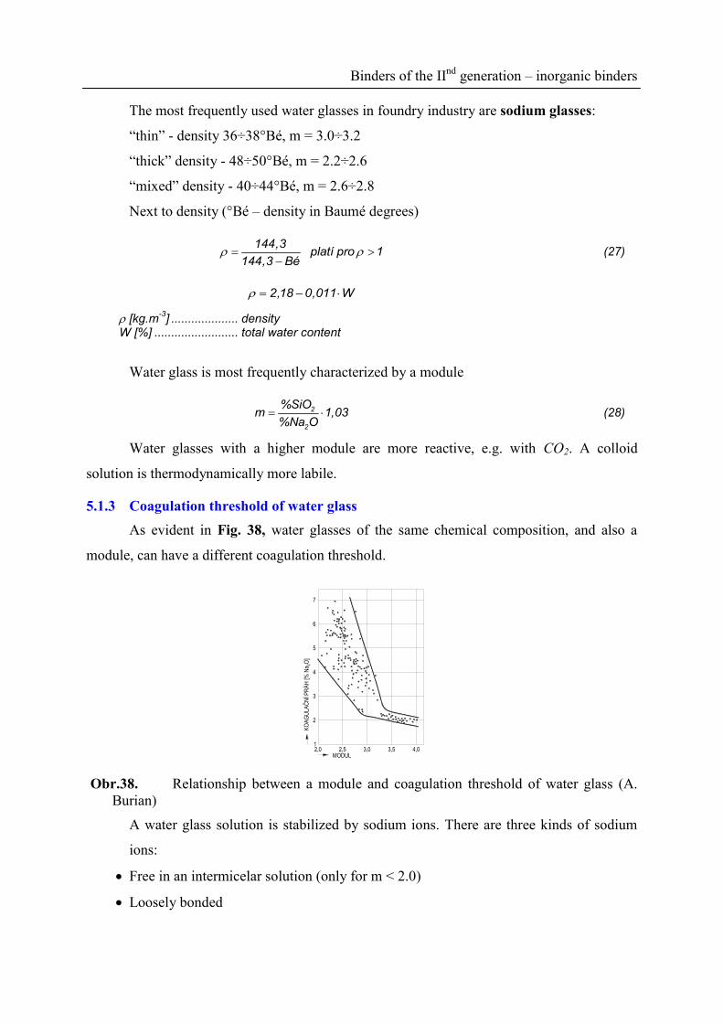
Binders of the IInd
generation – inorganic binders
The most frequently used water glasses in foundry industry are sodium glasses:
“thin” - density 36÷38°Bé, m = 3.0÷3.2
“thick” density - 48÷50°Bé, m = 2.2÷2.6
“mixed” density - 40÷44°Bé, m = 2.6÷2.8
Next to density (°Bé – density in Baumé degrees)
144,3
platí pro 1144,3 Bé
(27)
2,18 0,011 W
[kg.m-3
] .................... density W [%] ......................... total water content
Water glass is most frequently characterized by a module
2
2
%SiOm 1,03
%Na O (28)
Water glasses with a higher module are more reactive, e.g. with CO2. A colloid
solution is thermodynamically more labile.
5.1.3 Coagulation threshold of water glass
As evident in Fig. 38, water glasses of the same chemical composition, and also a
module, can have a different coagulation threshold.
MODUL2,0
KO
AG
ULA
ČN
Í PR
ÁH
[% N
a 2O
]
2,5 3,0 3,5 4,01
2
3
4
5
6
7
Obr.38. Relationship between a module and coagulation threshold of water glass (A.
Burian)
A water glass solution is stabilized by sodium ions. There are three kinds of sodium
ions:
Free in an intermicelar solution (only for m < 2.0)
Loosely bonded

Binders of the IInd
generation – inorganic binders
Tightly bonded
Not all Na+ participate in stabilization of the colloid solution. Free Na
+ ions in a
diffusion layer can be bonded by a specific amount of an acid (HCl) and thus an observable
coagulation can be initiated, leading to formation of gel. This amount of the acid is
recomputated to a corresponding amount of sodium ions and the coagulation threshold is then
expressed in % of Na2O:
A 2KP 0,31V %Na O (29)
VA [ml] HCl consumption = 1 mol.l-1
Through the coagulation threshold, processability of self-hardening mixtures and
many other properties of mixtures with water glass can be determined. Therefore assessment
of water glass should be based on density, a module and the coagulation threshold.
KOAGULAČNÍ PRÁH [% Na2O]
0 1 2 3 4 5 6 7 8 9
HO
DN
OT
A p
H
11
12
KOAGULAČNÍ PRÁH [% Na2O]
2 3 4 5 6 7
ZP
RA
C. S
MĚ
SI [
min
]
0
10
20
30
Obr.39. Dependence of the
coagulation threshold on pH of water
glass (A. Burian)
Obr.40. Dependence of
processability of a self-hardening
mixture with water glass on the
coagulation threshold (A. Burian)
5.2 CO2 process
Particularly during CO2 flowing through a disperse system of a mixture, intensive
chemisorption (higher pressure)
2 2 2 3CO H O H CO (30)
and drying of generated products (excess of CO2) occurs.
Water glass with a module 2.23.3 is considered a colloid solution with a different
degree of polycondensation of silicate anions. Dispersed phase systems belong among them.
Particles represent an individual base, separated by a dispersed environment. A phase
interface with a large surface is characterized by high surface energy and thus also
considerable thermodynamic instability. The solution pH is higher than 11. The basis of the
colloid solution comprises SiO2 particles with ion adsorption, while the so-called micelle

Binders of the IInd
generation – inorganic binders
forms. The scheme of the construction of the colloid micelle of the dihydrogen disilicic acid
in the presence of Na-ions is shown in Fig. 41.
Na+
Na+
Na+
Na+
Na+Na+
Na+
Na+
H+
H+
H+
H+
H+
H+H+
H+
H+
H+
H+H+
H+H+
H+
H+
SiO2-3
Si2O2-5
Si2O2-5
INTERMICELÁRNÍ
ROZTOK
JÁDRO(SiO2)n6
5
4
32
1
SiO2-3
SiO2-3
Obr.41. SiO2 colloid particle in alkaline silicate (1 – diffusion layer, 2 – compensation
layer, 3 –electric double-layer, 4 – micelle, 5 – particle, 6 – granule)
2
2 2 5 2 3H Si O SiO 2H SiO (31)
The main conditions for stability of these solutions include:
Very small dimension of particles (sedimentation of particles)
Electric charge of the same sign
Solvatation of particles (ions)
Both of the last conditions protect the colloid solution against self-coagulation. More
distant adsorbed H+, Na
+ ions form a diffusion layer of the micelle. Due to the motion of the
micelle in the solution, a part of adsorbed H+, (Na
+) ions remain tightly bonded and they
perform with a core the Brown motion, loosely bonded ions form a diffusion layer of a
variable thickness. Between the particles and the solution, a potential difference occurs –
electrokinetic potential (zeta) (Fig. 42).If the colloid particles form an adsorbed envelope of
ions, the relative stability of the system is conditioned by this. In the water-glass colloid
solution micelles in the alkaline environment the negative charge prevails, by which the
particular particles repel each other and the solution is relatively stable. The sole water glass
solution is formed by electrolyte. Ions enter the solvatation layer of particles and influence the
sole properties. Na+
ions dramatically reduce water movability, decreasing strongly the
solvatation sphere (growth of stability of Na-silicates, while the module decreases). The entire
solvate layer is saturated, if the concentration of Na+-ions reaches the value m = 2.0. At
higher concentration, Na+ transfer into the intermicelar solution.

Binders of the IInd
generation – inorganic binders
A
B C
PO
TE
NC
IÁL
E
E = +
Obr.42. Total electrokinetic potential of a micelle (A – particle, B – micelle, C – solution)
Adsorption (electric double-layer) is saturated, if the concentration in this layer
reached m = 4.0. These values cannot be exceeded. When increasing ion concentration,
degradation of hydration envelopes occurs by dehydration of ions. Dehydration process does
not occur on Na+, but on Na(OH2)
+ particles. Na
+ ions bind a coordinately bonded water
molecule, which defies dehydration process. When increasing the content of Na+-ions in the
adsorption layer, hydration may decrease max. to 1 mol H2O/mol Na+. Observations have
shown that at low concentrations of Na+ ions in the adsorption layer, the hydration is 1.8 mol
H2O/mol Na+. The growth of Na
+ ions in the diffusion layer leads to a decrease in their
hydration and H2O molecules transfer to the intermicelar solution. At m = 3.3, approximately
40 mol H2O/mol Na+ were measured; at the Na
+ ion growth and a decrease of the module (m
= 2.0), solvatation decreased to 9 mol H2O/mol Na+.
At CO2 hardening, the dihydrogen carbonic acid generates, causing a decrease in pH
value,
2 2 5 2 3 2 3
2
2 5
Na Si O H CO H O 2Na HCO
Si O 2H OH H
(32)
The diffusion layer compresses and in the strongly acidic atmosphere vanishes
completely. Therefore also a decrease in the electrokinetic potential – zeta occurs and a
system of a high value of a change of free enthalpy (G) forms. Its value may only decrease
at spontaneous growth of coarser particles at the expense of the smallest ones (a decrease in
the specific surface). However, very low solubility of colloid substances in the dispersive
phase prevents these processes. Then the only way is an increase of particles by coagulation –
aggregation. Coagulation of water glass is caused by coagulation ions (H+) with an opposite
sign than a colloid particle has. A binding component forms – silicic acid gel.
The coagulation runs most rapidly in a pH interval 5÷6, because particles migrate
through the so-called isoelectric point, they are not charged, therefore they aggregate quickly.

Binders of the IInd
generation – inorganic binders
In this pH region, the system has the lowest stability (Fig. 43). The higher mixture alkalinity,
the higher system stability. Water glasses with a low module and highly alkaline mixtures are
relatively more stable and much higher CO2 consumption is needed for hardening.
pH SOUSTAVY0 2 4 6 8 10 12
LOG
. DO
BY
VZ
NIK
U G
ELU
KATALYZÁTOR OH-
MIN
. ST
ÁLO
ST
MA
X. S
TÁ
LOS
T
Obr.43. Influence of pH on the time of coagulation of silicic acid until the gel forms
The main binding component – the gel of the acid – is the decisive strength
determining component after the CO2-reaction, on condition of the cohesion process of the
mixture destruction. The following is determining for strength of the silicic acid gel:
Sizes of particles and their distribution
Coordination number of particles
Stress in the gel (degree of dehydration)
Amount and a form of disengaging of by-products of reactions ( 2 3 2
3
Na CO xH O
NaHCO
,
CH3COONa.3H2O, glycerol).
A particle size growth through polymerization (monomer→dimer→cyclic polymer→
particle) and its aggregation is depicted in Fig. 44.
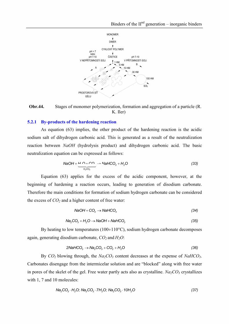
Binders of the IInd
generation – inorganic binders
MONOMER
DIMER
CYKLICKÝ POLYMER
ČÁSTICE
1 HM5 HM
10 HM
30 HM
100 HM
SOL
PROSTOROVÁ SÍŤ
GÉLU
A
B
V PŘÍTOMNOSTI SOLI
pH 7-10
V NEPŘÍTOMNOSTI SOLI
pH 7-10nebo
pH < 7
Obr.44. Stages of monomer polymerization, formation and aggregation of a particle (R.
K. Iler)
5.2.1 By-products of the hardening reaction
As equation (63) implies, the other product of the hardening reaction is the acidic
sodium salt of dihydrogen carbonic acid. This is generated as a result of the neutralization
reaction between NaOH (hydrolysis product) and dihydrogen carbonic acid. The basic
neutralization equation can be expressed as follows:
2 3
2 2 3 2
H CO
NaOH H O CO NaHCO H O (33)
Equation (63) applies for the excess of the acidic component, however, at the
beginning of hardening a reaction occurs, leading to generation of disodium carbonate.
Therefore the main conditions for formation of sodium hydrogen carbonate can be considered
the excess of CO2 and a higher content of free water:
2 3NaOH CO NaHCO (34)
2 3 2 3Na CO H O NaOH NaHCO (35)
By heating to low temperatures (100110°C), sodium hydrogen carbonate decomposes
again, generating disodium carbonate, CO2 and H2O:
3 2 3 2 22NaHCO Na CO CO H O (36)
By CO2 blowing through, the Na2CO3 content decreases at the expense of NaHCO3.
Carbonates disengage from the intermicelar solution and are “blocked” along with free water
in pores of the skelet of the gel. Free water partly acts also as crystalline. Na2CO3 crystallizes
with 1, 7 and 10 molecules:
2 3 2 2 3 2 2 3 2Na CO H O; Na CO 7H O; Na CO 10H O (37)
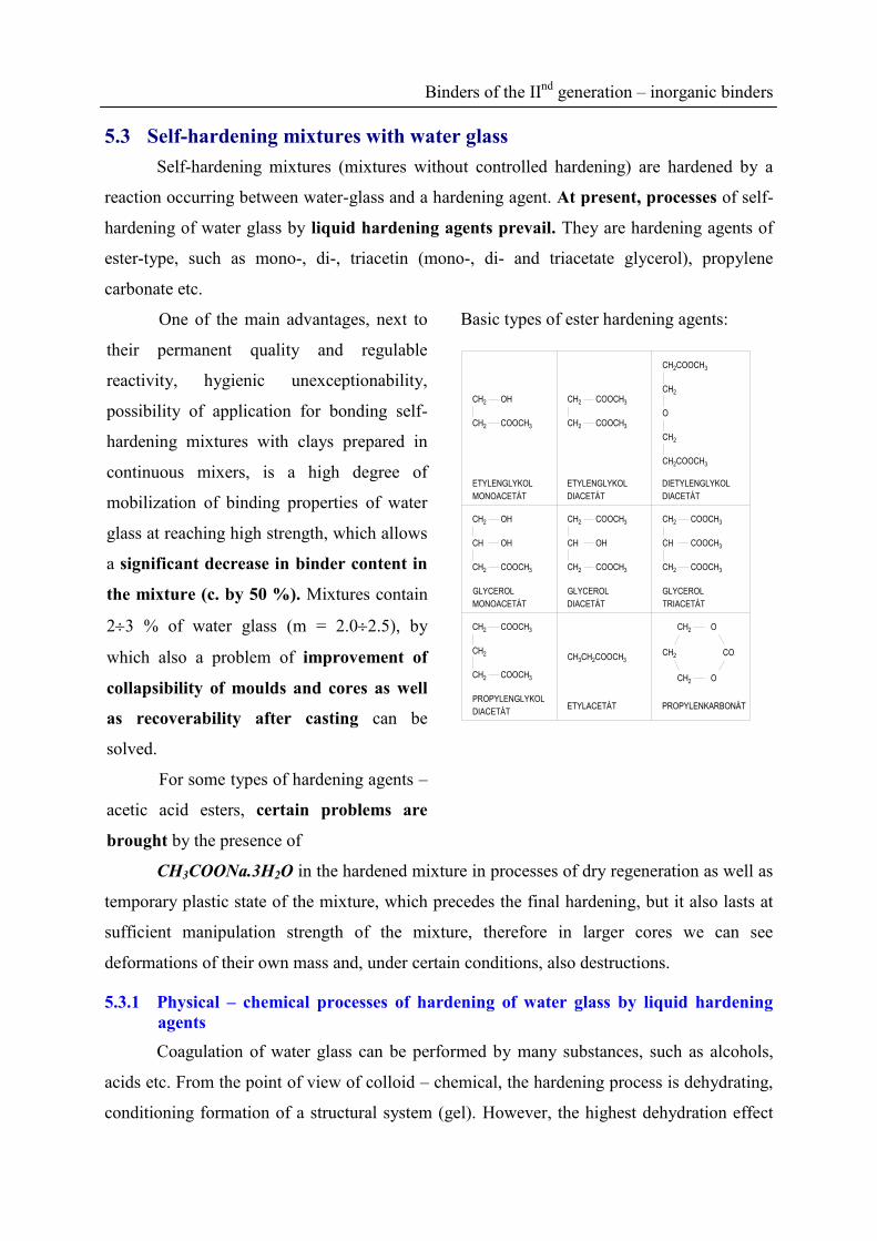
Binders of the IInd
generation – inorganic binders
5.3 Self-hardening mixtures with water glass
Self-hardening mixtures (mixtures without controlled hardening) are hardened by a
reaction occurring between water-glass and a hardening agent. At present, processes of self-
hardening of water glass by liquid hardening agents prevail. They are hardening agents of
ester-type, such as mono-, di-, triacetin (mono-, di- and triacetate glycerol), propylene
carbonate etc.
One of the main advantages, next to
their permanent quality and regulable
reactivity, hygienic unexceptionability,
possibility of application for bonding self-
hardening mixtures with clays prepared in
continuous mixers, is a high degree of
mobilization of binding properties of water
glass at reaching high strength, which allows
a significant decrease in binder content in
the mixture (c. by 50 %). Mixtures contain
23 % of water glass (m = 2.02.5), by
which also a problem of improvement of
collapsibility of moulds and cores as well
as recoverability after casting can be
solved.
For some types of hardening agents –
acetic acid esters, certain problems are
brought by the presence of
Basic types of ester hardening agents:
DIETYLENGLYKOL
DIACETÁT
ETYLENGLYKOL
DIACETÁT
ETYLENGLYKOL
MONOACETÁT
COCH2
CH2 O
CH2 O
CH3CH2COOCH3
CH2
COOCH3CH2
CH2 COOCH3
COOCH3
COOCH3CH2
CH2
CH
COOCH3COOCH3
CH
CH2
OH
CH2 COOCH3COOCH3CH2
OH
OHCH2
CH
CH2COOCH3
CH2
O
CH2
CH2COOCH3
COOCH3
COOCH3
CH2
CH2CH2
CH2 OH
COOCH3
GLYCEROL
TRIACETÁT
GLYCEROL
DIACETÁT
GLYCEROL
MONOACETÁT
PROPYLENKARBONÁTETYLACETÁTPROPYLENGLYKOL
DIACETÁT
CH3COONa.3H2O in the hardened mixture in processes of dry regeneration as well as
temporary plastic state of the mixture, which precedes the final hardening, but it also lasts at
sufficient manipulation strength of the mixture, therefore in larger cores we can see
deformations of their own mass and, under certain conditions, also destructions.
5.3.1 Physical – chemical processes of hardening of water glass by liquid hardening
agents
Coagulation of water glass can be performed by many substances, such as alcohols,
acids etc. From the point of view of colloid – chemical, the hardening process is dehydrating,
conditioning formation of a structural system (gel). However, the highest dehydration effect
Binders of the IInd
generation – inorganic binders
has a hydrogen atom (bonds high amount of water). This implies that H+-ion is the most
effective factor of formation of a structure.
The value of the electrokinetic potential decreases by H+-ions entering the
intermicelar solution, while weakening electrostatic repulsive forces between aggregates at
the same time, and after reaching a critical potential (the coagulation threshold value), before
achieving the isoelectric point, coagulation and transition of lyosol in gel occurs.
Gelation of water glass occurs at the increasing concentration of H+-ions in the
intermicelar solution with its dehydration effect at gradual bonding of Na+-ions in a form of
salts. Silicic acid particles do not aggregate only by van der Waals forces, but also by effect of
primary valences with a structure of three-dimensional polymer:
(HO)3 Si OH + HO Si (HO)3- H2O (HO)3 Si OH + HO Si O Si(OH)2 ONa
OH
OH (38)
Only OH- (ONa) groups at the end of the chain impede condensation, another type of
OH- groups forms transverse bonds. As the mixture has to have a certain processibility
(service life), it is necessary for H+-ions to enter the intermicelar solution slowly, gradually,
and be regulated.
Esters are organic matters formed from esterification reaction, by acids acting on alcohols:
wateresteracidalcoholH
OH
(39)
So that the general equation can proceed in the direction of hydrolysis (saponifying),
the alkaline environment and water must be ensured. As a result of hydrolysis of disodium
silicate,
2 2 2 2Na O nSiO mH O 2NaOH nSi m 1 H O (40)
sodium hydroxide forms, which is strongly dissociated, which results in the alkaline
character of the water glass solution. Through alkaline hydrolysis the equilibrium state moves
to the benefit of hydrolysis, as the forming acid is removed from the equilibrium state by
formation of salt.
In foundry operation esters of acetic acid and of two- to five-member polyhydric
alcohols have been most widely used. And from alcohol - glycerol (glycerin), there are
acetates.
Gradually generating acetic acid reacts with NaOH (from water glass).

Binders of the IInd
generation – inorganic binders
3 3 2CH COOH NaOH CH COONa H O (41)
while sodium acetate is forming, crystallizing as CH3COO.Na.3H2O, disturbing
compactness of the gel matter. Glycerol monoacetate undergoes hydrolysis most rapidly,
glycerol triacetate most slowly. The water glass hardening speed can be in summer (warm
sands – reaction retardation) or in winter climatic conditions (accelerating) regulated by
mutual ratio of particular acetines.
Obr.45. Structure of a binder envelope
with disengaged glycerol (syneresis,
SEM)
Obr.46. Grain envelope of a self-
hardening mixture hardened by liquid
hardening agents with disengaged
crystals CH3COONa.3H2O (SEM)
5.3.2 Reactivity and optimal concentration of an ester-type hardening agent
The course of the reaction of an ester and alkaline silicate can be divided to three
stages (Fig. 47). Stage I – called also the “incubation period”. In this stage hydrolytic
cleavage of esters (in the alkaline environment) to alcohol (glycerol) and an acid (acetic acid)
occurs. The length of the stage I depends on a free water content (in water glass) and a type of
ester. The entire system reactivity can be controlled by a combination e.g. of monoacetin (the
fastest hydrolysis) and triacetin (the slowest hydrolysis). If there was no free water in the
binder (if coacerate is used), gelation does not occur even after several days.

Binders of the IInd
generation – inorganic binders
DOBA REAKCE [min]0
PE
VN
OS
T [M
Pa] ŽIVOTNOST SMĚSI
I. II. III.
ŽÁ
DA
NÁ
PE
VN
OS
T
Obr.47. Course of the reaction of an ester and alkaline silicate
Stage II is characterized by initiation of gelation and beginning of the plastic state of
the self-hardening mixture. Although the mixture has the handling strength already, plastic
deformation of moulds and cores occurs under bending loading. In contrast to CO2-process,
when water in gel is quickly removed by an excess of CO2 (stage II is missing), in a reaction
with esters a considerable part remains blocked by gel and is the cause of the existence of the
plastic state (Fig. 48). Pursuant to some authors, the presence of glycerol in the grain
envelope also contributes to the plastic state. On the contrary, this condition is very
favourable from the point of view of lifting-out patterns and disassembling core boxes. In this
time of stage II the service life of the mixture is over, this means the time from the mixture
preparation, when after compacting the satisfactory final (demanded) strength (minimal wear)
is reached.
Stage III – the plastic state ends here and moulds (cores) obtain the required strength.
Obr.48. Testing of the plastic state of self-hardening mixtures with
water glass Gradual bending of cores to fracture
The commonly used binders (m = 2.22.5) need 812 mass % of the ester hardening
agent (diacetin + triacetin) for water-glass. Then, aside from the free water amount, binder
amount and its coagulation threshold, ester content is decisive for the reaction speed as well.
The higher ester concentration, the more reactive the binder system, the mixture service life
and also the time of the plastic state get shortened, the mixture becomes hardened rapidly,
however, final strength is lower and the mixture is more brittle. Insufficient amount of a
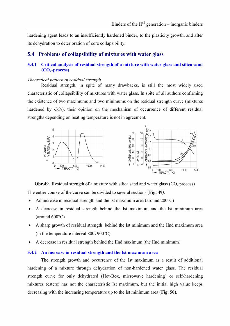
Binders of the IInd
generation – inorganic binders
hardening agent leads to an insufficiently hardened binder, to the plasticity growth, and after
its dehydration to deterioration of core collapsibility.
5.4 Problems of collapsibility of mixtures with water glass
5.4.1 Critical analysis of residual strength of a mixture with water glass and silica sand
(CO2-process)
Theoretical pattern of residual strength
Residual strength, in spite of many drawbacks, is still the most widely used
characteristic of collapsibility of mixtures with water glass. In spite of all authors confirming
the existence of two maximums and two minimums on the residual strength curve (mixtures
hardened by CO2), their opinion on the mechanism of occurrence of different residual
strengths depending on heating temperature is not in agreement.
TEPLOTA [°C]0
0
PE
VN
OS
T
V T
LAK
U
t [M
Pa]
200 600 1000 1400
1
2
3
4
0 200 600 1000 1400TEPLOTA [°C]
0,5
OB
JEM
OV
Á H
MO
TN
OS
T
[g.c
m-3
]
1,7
1,5
1,3
1,1
0,9
0,7v
[%]
-4
0
4
8
12
16
ZM
ĚN
A O
BJE
MU
V
[%]
0
10
20
30
40
50
V
v
Obr.49. Residual strength of a mixture with silica sand and water glass (CO2 process)
The entire course of the curve can be divided to several sections (Fig. 49):
An increase in residual strength and the Ist maximum area (around 200°C)
A decrease in residual strength behind the Ist maximum and the Ist minimum area
(around 600°C)
A sharp growth of residual strength behind the Ist minimum and the IInd maximum area
(in the temperature interval 800900°C)
A decrease in residual strength behind the IInd maximum (the IInd minimum)
5.4.2 An increase in residual strength and the Ist maximum area
The strength growth and occurrence of the Ist maximum as a result of additional
hardening of a mixture through dehydration of non-hardened water glass. The residual
strength curve for only dehydrated (Hot-Box, microwave hardening) or self-hardening
mixtures (esters) has not the characteristic Ist maximum, but the initial high value keeps
decreasing with the increasing temperature up to the Ist minimum area (Fig. 50).

Binders of the IInd
generation – inorganic binders
A content of Na+ ions in the diffusion layer of micelles determines the coagulation
threshold (% Na2O). For the water glass binding properties to be fully utilized, in self-
hardening mixtures a specific amount of ester (related to coagulation threshold) is needed for
hardening process and, at the same time, also a certain amount of free water (hydrolysis). A
small amount of ester results in a high content of undecomposed “residual” water glass, which
dehydrates by heat and influences particularly the Ist maximum of residual stress
(collapsibility).
600 700 800 900
4
8
12
16
20
24
28
8%
12%
0
TEPLOTA ŽÍHÁNÍ [°C]
0
ZB
YT
KO
VÁ
PE
VN
OS
T
V T
LAK
U [M
Pa]
100 200 300 400 500
Obr.50. Process of residual strength in compression (water-glass 3 %, M = 2.5) in a
mixture with 8 and 12 % of esters (diacetin – triacetin) for the water-glass content
The Ist maximum is completely missing for optimally hardened self-hardening mixtures.
5.4.3 Decrease in residual strength behind the Ist maximum and area of the Ist
minimum (approximately 600°C)
Decreasing of residual strength behind the Ist maximum was most frequently related to
the discontinuous reversible change in the quartz modification →SiO2, occurring at 573°C,
which is in accordance with the curve minimum temperature. Later was shown that other
influences also affect the crack formation in envelopes of a binder. These are above all
dehydration processes in disodium silicate (non-hardened water glass) and silicic acid gel
with regard to their high adhesion strength to the silica sand surface.
5.4.4 Sharp growth of residual strength behind the Ist minimum and the area of IInd
maximum (800900°C)
Behind the Ist minimum a rapid growth of residual strength with a maximum at
800900°C occurs. The IInd maximum value is substantially higher than that of the Ist
maximum. Most of authors explain the strength growth by the liquid phase formation,
occurring according to the binary system SiO2 - Na2O above 793°C, which at first joins-up

Binders of the IInd
generation – inorganic binders
formerly formed cracks, the binder envelope transforms into molten glass attacking even the
silica sand surface and under high temperatures the envelope – grain surface interface dies
out, while forming a compact monolith of high residual strength. Strength in the IInd
maximum area is determined not only by water glass content, but also by its module. Some
authors come into a general conclusion that the IInd maximum is a function of the total
content of Na2O in the mixture.
5.4.5 Decrease in residual strength behind the IInd maximum (the IInd minimum)
The original opinion assumes that along with the temperature growth above 800°C
(the IInd maximum), as a result of SiO2 diffusion growth in the direction from the sand grain
to the melt the mixture melting accelerates, the Na2O concentration in the melt slowly
decreases and during cooling to the normal temperature the individual SiO2 crystals begin to
crystallize from the melt. The crystals play a part of “foreign inclusions” in the solidifying
molten glass and act as inner notches generating local stress concentrations. The higher
heating temperatures, the higher concentration of foreign inclusions and the cooled-down
mixture with high internal stress has low residual strength.
The strength of molten grain envelopes is not influenced only by the presence of
“foreign inclusions” and processes on the grain – envelope boundary, but also by permanent
changes in sand volume. A mixture, especially from mineralogically pure washed sands,
begins to expand strongly above 800°C. A cause is a transition of -SiO2 into cristobalite,
which is catalyzed by the presence of Na+ ions; the quartz specific weight decreases from the
initial 2.65 to 2.33 g.cm-3
, while the mixture increases its volume by as much as 40 %. While
the residual strength of the mixture with water glass above 1000°C is relatively low, cleaning
of thermally stressed cores is highly difficult. Expansion of the mixture is very significant,
having two different effects here; it disintegrates testing elements, thus reducing the residual
strength behind the IInd maximum, however, substantial permanent changes in a volume
initiate tensions, which the mixture is not able to relax in spite of all its plasticity, they cause
the residual stress growth, thus leading to impaired collapsibility.
5.4.6 Possibilities of control of residual strength with water glass (CO2 – process)
Additives containing Al2O3 belong to very effective substances influencing the IInd
maximum area. As the cause of the IInd maximum is formation of melt, the move to high
temperatures is explained by transition of the binary system Na2O - SiO2 to the ternary Al2O3 -
SiO2 - Na2O with a high melting point (viscosity change).

Binders of the IInd
generation – inorganic binders
Another favourable effect of Al2O3 on collapsibility is stabilization - SiO2 against
transition to cristobalite related to the continuous expansion growth of the mixture with silica
sand.
5.5 Hardening of alkaline silicates by dehydration processes
Strength approximately by an order of magnitude higher than when using chemical
processes (CO2-process, ST mixtures with esters) can be reached by physical dehydration of
mixtures bonded by Na-silicates using Hot-Box or microwave hardening. While the silicate
module decreases, the strength of dehydrated mixtures increases.
This enables to reduce the binder content (Na2O content) dramatically, with favourable
effects on collapsibility and recoverability of silica sand. Dehydration is a reversible process.
However, for conventional procedures a longer storability of cores is required. This depends
on storage conditions (relative air humidity, temperature) and it is necessary to stabilize the
binder system by a modification, such as reduction products of monosaccharides (glucitols) or
organosilanes.
5.5.1 Collapsibility of cores
The binder system dehydration process can be used to de-core castings, e.g. in water,
possibly even with a subsequent wet self-regeneration of base sand. Rehydration causes
sudden drop in strength while increasing volume weight of cores.
The collapse of cores occurs to 60 minutes of immersion in water at the latest. If hot
cores were immersed in water (for instance together with a casting), their self-destruction
occurs to 2 minutes. This may be called the “wet regeneration” of base sand, however, there is
an ensuing problem of waste water salt content (re-crystallization, neutralization, etc.).
6 Binder of the IInd
generation – organic binders
6.1 Organic-based foundry binders
Organic binders have found their use in preparation of core mixtures and have enabled
manufacture of cores by new progressive procedures. The mixtures have high strength after
hardening (above all in bending), low thermal destruction temperature, thus relating rapid
decrease in strength and in resistance of a core (collapse) to metal shrinkage and mainly
excellent collapsibility. Further, cores have high stability (this means adequate storability) and
mixtures are easy to regenerate both mechanically and pneumatically, at dry condition.

Binders of the IInd
generation – organic binders
Thermal regeneration using expensive base sands can be applied, too. The mixtures feature
excellent flowability, therefore they can be blown (dry coated mixtures) or injected.
Cores have high strength, which is necessary for the manufacture of complicated thin-
walled shapes. The binder efficiency can be expressed using specific strength, this means
strength corresponding to 1% of a binder. The minimum binder content is observed in term of
economical, hygienic, but even technological point of view (minimal development of gases –
exogenous blow holes). Older types of organic binders, such as saccharides and animal and
vegetable oils, have been replaced by artificial resins nowadays. Up to now, phenolic, furan,
urea, alkyd, polyurethane, epoxy, acrylate and other resins have been applied, however, the
development is hobbled by more and more strict standards for living and working
environment, as well as unknowingness of effects of many emissions and immisions on a
living organism at minimum concentration but long-term exposure.
6.1.1 Chemistry of phenolic binders
A survey of types of phenolic binders and their applications in various technologies is
shown in Fig. 51.
FENOL : FORMALDEHYD
POLYKONDENZACE
V PROSTŘEDÍZÁSADITÉMKYSELÉM
FENOL. PRYSKYŘICE
TYP RESOL
FENOL. PRYSKYŘICE
TYP NOVOLAK
TEPLO (+KYSELINA) KYSELINA
POLYKONDENZÁT
VE STAVU REZITU
POLYKONDENZÁT
VE STAVU REZITU
HEXAMETYLTETRAAMIN
+ TEPLO
SMĚSNÝ POLYKONDENZÁT
VE STAVU REZITU
SAMOVOLNĚ TUHNOUCÍ
COLD - BOX (GISAG), NO - BAKEHOT - BOXSKOŘEPINOVÉ FORMOVÁNÍ
C - METODA
(1:1 ÷ 1:3)(1:0,4 ÷ 1:0,9)
VÝROBA
POJIVA
VYTVRZOVÁNÍ
Obr.51. Phenol-formaldehyde binders and various technologies using phenolic resins.
6.1.2 Shell moulding, the Croning method, “C” method
This is a manufacturing method for thin-walled or mainly hollow cores from dry,
perfectly loose mixture, which commonly comprises silica sand, heat meltable and hardenable
resins and possibly other additives. A shell is formed by a gradual melting of a mixture layer
by heat of a heated pattern or core box (240280°C). Further heating has a hardening effect,
and then a finished shell mould (masque) with highly precise dimensions is removed from the
(metal) pattern. A shell wall thickness is reached by removing a loose non-molten mixture
after the time needed to achieve the required wall thickness, or for shell moulds with a
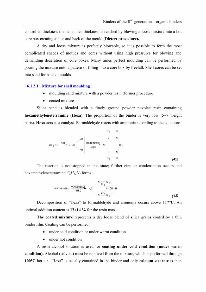
Binders of the IInd
generation – organic binders
controlled thickness the demanded thickness is reached by blowing a loose mixture into a hot
core box creating a face and back of the mould (Dietert procedure).
A dry and loose mixture is perfectly blowable, so it is possible to form the most
complicated shapes of moulds and cores without using high pressures for blowing and
demanding deaeration of core boxes. Many times perfect moulding can be performed by
pouring the mixture onto a pattern or filling into a core box by freefall. Shell cores can be set
into sand forms and moulds.
6.1.2.1 Mixture for shell moulding
moulding sand mixture with a powder resin (former procedure)
coated mixture
Silica sand is blended with a finely ground powder novolac resin containing
hexamethylenetetramine (Hexa). The proportion of the binder is very low (57 weight
parts). Hexa acts as a catalyst. Formaldehyde reacts with ammonia according to the equation:
H2 H
2CH2 = O2NH3
2 CH2
NH
NH
KONDENZACE
-2H2O
N
NH
C
H2
CH2
NC
H (42)
The reaction is not stopped in this state; further circular condensation occurs and
hexamethylenetetramine C6H12N4 forms:
6HCHO + 4NH3
KONDENZACE
-6H2ON
CH2
CH2
CH2N
N
N
CH2
CH2
H2C
(43)
Decomposition of “hexa” to formaldehyde and ammonia occurs above 117°C. An
optimal addition content is 1214 % for the resin mass.
The coated mixture represents a dry loose blend of silica grains coated by a thin
binder film. Coating can be performed:
under cold condition or under warm condition
under hot condition
A resin alcohol solution is used for coating under cold condition (under warm
condition). Alcohol (solvent) must be removed from the mixture, which is performed through
100°C hot air. “Hexa” is usually contained in the binder and only calcium stearate is then

Binders of the IInd
generation – organic binders
dosed into mixtures. Stearate acts as a separating agent – “grease”. The melting point is
148°C. Disadvantages of this former procedure are as follows:
Low output of preparation
Alcohol, representing 30 % of the resin mass, needs to be removed from the mixture,
which is difficult for pollution of air by alcohol vapours, for a danger of fire, explosion
(occupational safety). Complete removal of alcohol is mostly unperformable, its residues
cause many defects, such as “sintering of sand” in reservoirs, “shell bits peeling-off”, local
thinning of a shell.
Advantages are a possibility to make the equipment by own, lower price as well as
energy demands.
Coating under hot condition – formation of a resin film is reached by melting a
novolac resin just in a mixer by effect of heat of hot sand at temperature about 130150°C
(sand temperature must be by 5060°C higher than the resin melting point). Then no solvent
is needed, the resin can be even roughly ground (cheaper). There are no problems with
residual alcohol. When mixing, the mixture temperature is decreasing; “hexa” in an aqueous
solution and hard wax is added at 120100°C. The binder content ranges between 2.74.4
weight parts.
Disadvantages of this procedure are as follows:
Expensive equipment (e.g. Fordath 2000)
Higher energy demands, the mixtures have a higher tendency to crack
formation
Advantages – a higher quality mixture is obtained, the preparation is highly cost-
effective, less problems with air cleanliness, high output of the equipment, the mixture is
storable actually without any limits.
6.1.2.2 C-method present-day development
Binders with high collapsibility even for light metals casting have been developed.
Formerly whole cores could be only removed by heat treatment (annealing). Step by step, free
phenol proportion in resins below 1% occurs and next to just described preparation
procedures of coated mixtures, the fusion coating (under hot condition) has been applied,
which reduces the resin proportion markedly, thus leading to emissions reduction as well. C –
method has found its use also in the manufacture of the most demanding castings:
Cores of hydraulic elements

Binders of the IInd
generation – organic binders
Thin-walled cores of cooling water jackets
Shell cores and forms for ribbed cylinders and crankshafts
6.1.3 Hot-Box method
In years 19591960 a new method of the manufacture of castings started to be
widespread for large-series production through automatization of the whole process. The Hot-
Box method makes precise cores just in metal Hot-Boxes, where injected bonding mixture is
hardened by heat. In contrast to coated mixtures the HB method uses bonding mixtures, often
based on water soluble binders injected into a core box.
For the HB method the following binders are used:
Urea-formaldehyde
Melamine-formaldehyde
Furan
Phenol-formaldehyde (resoles)
Modified Na-silicates and salt solutions (see inorganic binders)
Hardening of cores begins from the hot core box surface (180300°C, according to the
binder type) and with regard to high thermoreactivity of binders the rapid surface hardening
occurs (1445 sec) and a core gains an adequate handling strength. After taking the core out,
final hardening throughout the whole cross section by accumulated heat occurs. The Hot-Box
method must be used for the manufacture of full volume cores, which is the main
difference in comparison with the C – method. On the one hand, a very expensive coated
blend, on the other hand, a cheaper material for Hot-Boxes, from which full cores can be
made. However, the core is harder and is cast in a casting device without dusting. All
common types of mixers can be used for preparation of the mixtures. However, the mixed
mixture needs to be stored for as short time as possible. It is important to realize, that mixture
hardening begins just from the moment of adding a binder into the mixture of a catalyst and
sand. Acidic catalysts ensure especially short production cycle (latent hardening agents, salts
of inorganic or organic acids, e.g. ammonium nitrate). Resoles belong to the most widely used
binders.

Binders of the IInd
generation – organic binders
6.1.3.1 Other variants of the Hot-Box technology
Hot-Box Plus – a special procedure for an extreme long service life of a mixture. A
disadvantage is a relatively long hardening time and also higher thermal stability of cores
during casting.
Warm-Box – the hardening temperature is decreased to 140200°C in this
technology. The time of core hardening is comparable to the Hot-Box procedure. Modified
furan resins and a special hardening agent based on sulfonic acid salts are used as binders.
The binder content is reduced to 0.91.2% (hardening agent content 2030 % for the binder
mass). The advantage of this procedure is a lower energy demandingness and reduction of gas
content during casting. Due to advantageous tensile strength under hot condition, the cores are
used for lightweight alloys castings (cylinder heads).
Thermal shock – hardening is performed for a short period (by a shock) at
temperatures of 280300°C and the hardening reaction is finished by effect of the
accumulated core heat. Highly condensed phenolic resins and ureas serve as a binder, acidic
salts serve as a hardening agent. This technology is used e.g. for radiator cores manufacturing.
6.1.4 Cold-Box method
Cold-Box methods were developed for small batch production with the use of special
wood core boxes - PUR Cold-Box technology in 1967 and GISAG Cold-Box in 1968. The
development trend in the present days lies in expanding of cold procedures – NO BAKE in a
mould
self-hardening mixtures (without controlled hardening); a continuous preparation process
of immixing a hardening agent or a catalyst (Alfa-set, furan mixtures)
with controlled hardening, extrinsic hardening (CO2, SO2, TEA, air, formiate etc.)
From the point of view of chemical process of hardening, the self-hardening mixtures
NO BAKE can be divided to acidic or alkaline. While furan and phenolic resins are hardened
by strong acids, alkaline Na-silicates and alkalized phenolic resins are ester-hardened. The
phenolic resol can be self-hardened in a strong acid environment under cold condition. This is
the Cold-Box Gisag principle.
6.1.4.1 Cold – Box GISAG
A resol resin is mixed with silica sand. This mixture is put into a special core-making
machine. This incorporates a quick-mixer, where during several seconds (210) the mixture is
mixed with a catalyst (GH - GISANOL H), which is actually a strong acid. Then the entire
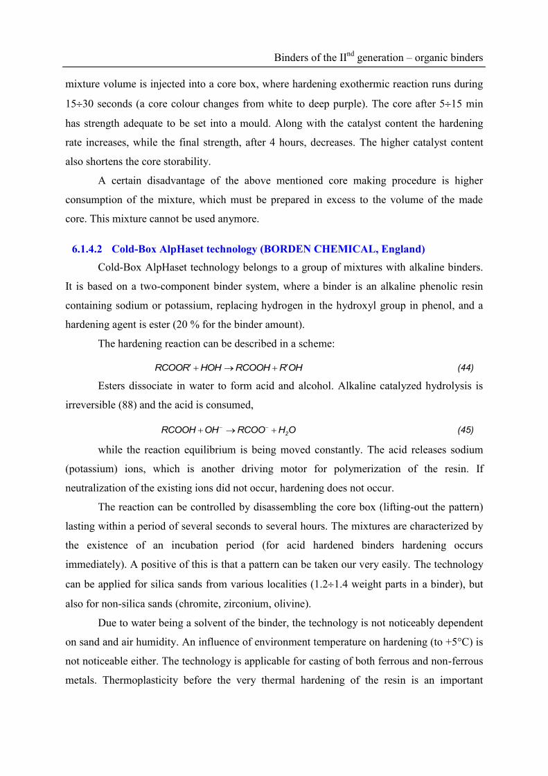
Binders of the IInd
generation – organic binders
mixture volume is injected into a core box, where hardening exothermic reaction runs during
1530 seconds (a core colour changes from white to deep purple). The core after 515 min
has strength adequate to be set into a mould. Along with the catalyst content the hardening
rate increases, while the final strength, after 4 hours, decreases. The higher catalyst content
also shortens the core storability.
A certain disadvantage of the above mentioned core making procedure is higher
consumption of the mixture, which must be prepared in excess to the volume of the made
core. This mixture cannot be used anymore.
6.1.4.2 Cold-Box AlpHaset technology (BORDEN CHEMICAL, England)
Cold-Box AlpHaset technology belongs to a group of mixtures with alkaline binders.
It is based on a two-component binder system, where a binder is an alkaline phenolic resin
containing sodium or potassium, replacing hydrogen in the hydroxyl group in phenol, and a
hardening agent is ester (20 % for the binder amount).
The hardening reaction can be described in a scheme:
RCOOR HOH RCOOH ROH (44)
Esters dissociate in water to form acid and alcohol. Alkaline catalyzed hydrolysis is
irreversible (88) and the acid is consumed,
2RCOOH OH RCOO H O (45)
while the reaction equilibrium is being moved constantly. The acid releases sodium
(potassium) ions, which is another driving motor for polymerization of the resin. If
neutralization of the existing ions did not occur, hardening does not occur.
The reaction can be controlled by disassembling the core box (lifting-out the pattern)
lasting within a period of several seconds to several hours. The mixtures are characterized by
the existence of an incubation period (for acid hardened binders hardening occurs
immediately). A positive of this is that a pattern can be taken our very easily. The technology
can be applied for silica sands from various localities (1.21.4 weight parts in a binder), but
also for non-silica sands (chromite, zirconium, olivine).
Due to water being a solvent of the binder, the technology is not noticeably dependent
on sand and air humidity. An influence of environment temperature on hardening (to +5°C) is
not noticeable either. The technology is applicable for casting of both ferrous and non-ferrous
metals. Thermoplasticity before the very thermal hardening of the resin is an important

Binders of the IInd
generation – organic binders
characteristic. So the binder compensates the braked thermal dilatation generated tension of
base sands, thus preventing formation of tension generated defects (fins, cracks). As to
hardening, this is even two-stage hardening of moulds, cores. The first stage is characterized
by low cross-linking of the binder and when heated, the plastic state occurs. Only at higher
temperatures spatial cross-linking occurs, thus achieving high strength, dimensional stability
and erosion resistance of the mould. The absence of sulfur, phosphorus and the minimum
nitrogen content gives priority to this technology for steel castings and spheroidal graphite
iron (SGI).
A big problem for the development of this technology was recoverability of base sand.
An assessment of a regenerate quality is performed according to loss on ignition (the amount
of residues of a resin and a catalyst) and granulometry changes (particulate matter proportions
below 0.125 mm). The loss on ignition indicates also an increased level of alkaline salts,
resulting in shortening of the service life of a new mixture with a regenerate. A type of the
present salts depends on ester types. Salts formed at higher temperatures are not soluble. At
low temperatures, they are soluble in resins applied when re-using the regenerate. A ratio of
soluble to dissoluble salts depends on thermal exposure of moulds. The present alkali salts
easily bind to newly added resins, the number of the present ions increases, thus accelerating
neutralization processes and shortening the service life of the mixture (the incubation period).
This negative effect of salts can be reduced by addition of water immediately before addition
of a resin. An addition of c. 0.2 % of water decelerates the neutralization process and returns
the original equilibrium to the binder system again.
The mixture can be regenerated successfully by a dry mechanical method.
Approximately 8590 % of a regenerate can be used. The mixture does not contain organic
solvents and hygienic conditions during casting are more favourable than for acid hardened
systems. Advantages of this technology:
Reduced tendency to occurrence of fins
Reduced tendency to formation of pinholes and blow holes
Reduced occurrence of cracks
Low sensitivity to temperature and humidity
Easier disassembling of core boxes
Quality surface of castings
Binders of the IInd
generation – organic binders
Absence of sulfur, nitrogen and phosphorus does not cause surface and subsurface
defects in castings of SGI (pinholes, degradation of the graphite shape, blow holes)
6.2 Chemistry of furan binders
Three types of furan resins are used as foundry binders:
Furan amine aldehyde resins based on fural, furfuryl alcohol, formaldehyde and urea.
They are intended for the manufacture of moulds and cores for castings of grey cast iron
(they contain nitrogen).
Furanresins based on fural, acetone and formaldehyde. These are nitrogen-free binders,
significantly more expensive, intended for the manufacture of moulds and cores for steel
castings.
Fural resins
Generally, furan resins are sorted according to the content of nitrogen (011 %) and
water (030 %). The higher the concentration of furfuryl alcohol in the binder, the better the
technological properties of the self-hardening mixture, however, the higher the price is. For
steel castings, resins containing to 1.5% of nitrogen are advisable.
The furan binder characteristics:
Content of furfuryl alcohol
Free and disengaging formaldehyde (in the resin 0.2 %)
Content of nitrogen and water
6.2.1 Self-hardening furan mixtures
Polycondensation is running, while acidic catalysts are acting (2060 % for the resin
mass):
Trihydrogen phosphoric acid H3PO4 (7580 %),
Arylsulphonic (benzenesulphonic) acid,
SO3H
Para-toluenesulphonic acid (PTS).
CH3 SO3H
The hardening reaction is exothermic, water is generated. This must evaporate,
therefore the hardening process runs in the direction from the surface inwards the core. For

Binders of the IInd
generation – organic binders
the manufacture of large moulds and cores, drying off by hot air is recommended. The
hardening process is accompanied by a mixture colour change – the original white colour
changes to dark-green to black. This causes troubles when checking indefectibility of
covering of the cores with black graphite coatings. An over-catalyzed mixture is usually
brittle, friable and of “pepper and salt” colour.
Rapid hardening can be reached by benzoic acid, xylene-sulfonic acid, benzene-
sulfonic acid and a mixture of inorganic acids. To increase reactivity, an addition of H2SO4 in
a catalyst (0.515 % of free H2SO4) is used, too.
Catalysts are a source of sulfur (SO2), which is also a part of a regenerate. The sulfur
content growth leads to:
Casting defects, degradation of nodular graphite (reduction of Mg modificate in cast
iron, MgS forms as a result of reactions); this can be solved also by special coatings,
allowing bonding of SO2
Deterioration of the work environment (SO2)
Exogenous blow holes
The hardening reaction speed increases along with increased temperature, therefore we
must work with cold sands. Regarding to acidic catalysts, alkaline base sands cannot be used
(chromium magnesite, magnesite). An advantage of the self-hardening furan mixture is that
coke forms at temperatures of 1100 to 1200°C without air access. The coke number ranges
from 43 to 53 (4353 % of coke from the resin mass). A large proportion of pyrolytic carbon
after thermodestruction of the resin improves the surface quality of castings cast even into
non-coated moulds. The mixture has also excellent collapsibility and easily regenerates by a
dry mechanical way.
6.2.2 Cold processes – extrinsic hardening
Advantages of CO2-process performed in the 50s are more and more often utilized
today in new cold processes in controlled hardening from outside the core box by gaseous or
aerosol media. At present these procedures belong to the most widely used processes of the
manufacture of moulds and mainly cores.
6.2.3 SO2 – process (furan resin)
When using furan resins, the principle lies in their polycondensation in the acidic
atmosphere of sulfuric acid. Supplied sulfur dioxide is oxidized to sulfur trioxide, which
forms sulfuric acid by chemisorption in water:
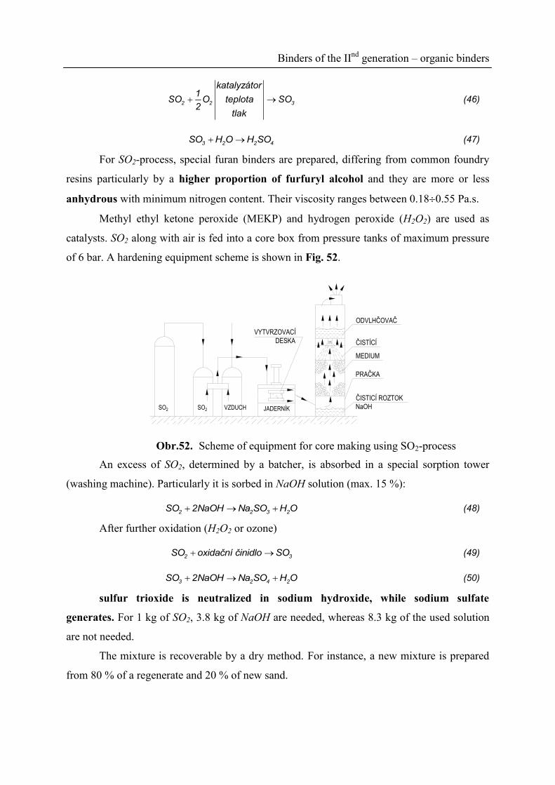
Binders of the IInd
generation – organic binders
2 2 3
katalyzátor1
SO O teplota SO2
tlak
(46)
3 2 2 4SO H O H SO (47)
For SO2-process, special furan binders are prepared, differing from common foundry
resins particularly by a higher proportion of furfuryl alcohol and they are more or less
anhydrous with minimum nitrogen content. Their viscosity ranges between 0.180.55 Pa.s.
Methyl ethyl ketone peroxide (MEKP) and hydrogen peroxide (H2O2) are used as
catalysts. SO2 along with air is fed into a core box from pressure tanks of maximum pressure
of 6 bar. A hardening equipment scheme is shown in Fig. 52.
ODVLHČOVAČ
ČISTÍCÍ
MEDIUM
ČISTICÍ ROZTOK
NaOHSO2 SO2 VZDUCH JADERNÍK
VYTVRZOVACÍ
DESKA
PRAČKA
Obr.52. Scheme of equipment for core making using SO2-process
An excess of SO2, determined by a batcher, is absorbed in a special sorption tower
(washing machine). Particularly it is sorbed in NaOH solution (max. 15 %):
2 2 3 2SO 2NaOH Na SO H O (48)
After further oxidation (H2O2 or ozone)
2 3SO oxidační činidlo SO (49)
3 2 4 2SO 2NaOH Na SO H O (50)
sulfur trioxide is neutralized in sodium hydroxide, while sodium sulfate
generates. For 1 kg of SO2, 3.8 kg of NaOH are needed, whereas 8.3 kg of the used solution
are not needed.
The mixture is recoverable by a dry method. For instance, a new mixture is prepared
from 80 % of a regenerate and 20 % of new sand.

Binders of the IInd
generation – organic binders
Assessment in term of hygiene and work safety - SO2 is poisonous. It can be detected
at as low concentration as 2 ppm. It is strongly aromatic (the worst smelling technology). In
spite of the problems mentioned above, the method is widely used in USA (more than 70
foundries), but also in Europe, China, Japan and even in South Africa.
Advantages of this technology:
Long service life of the prepared mixture
Unlimited storability of prepared cores
High specific strength (3 MPa in bending per 1% of the resin)
Low generation of vapours and gases during casting
Excellent collapsibility of cores after casting
The mixture sticks on patterns only at a minimum extent, gives smooth casting surfaces
with a decreased occurrence of surface defects
One of the shortest times of hardening (35 sec)
6.2.4 Resol-CO2
The binding process principle is in the alkaline condensation of phenol-formaldehyde
resin hardened by CO2-process. The resin is modified by a complex additive (pH = 14). A
high pH value is reached by the presence of KOH and K2CO3 in a binder. During hardening of
CO2, a decrease in pH towards the acidic side occurs. By the 1st stage CO2 hardening, an
immediate strength occurs, then final hardening follows after lifting the core out from the core
box.
In the first stage, adsorption of CO2 in water occurs, while dihydrogen carbonic acid
generates, reacting with alkaline resin in the presence of boritane ions, followed by gelation
and cross-linking of the binder. The reaction is exothermic. The reaction rate is influenced by
the mixture temperature and the pressure in the core box. The amount of the binder ranges
between 1.23.0 weight parts in modified phenol resin (for base sand).
The hardening rate for CO2 is approximately 56 l.min-1
at 0.030.05 MPa pressure.
Strength of cores is lower than for CO2 - water-glass, therefore this technology is applicable
for simple shaped cores. After casting of cast iron and steel castings, collapsibility is
noticeably better. A combination of the cores to bentonite moulds is not recommended.
“Excessive natrification” of bentonite occurs, therefore also strength decreases in a water
condensation zone. The use of olivine sands is not recommended, either.

Binders of the IInd
generation – organic binders
6.3 Chemistry of polyurethane binders
6.3.1 Phenolic polyurethane system
It is used as:
PEP-SET, three-component self-hardening system
COLD-BOX Ashland, with controlled hardening using tertiary amines
6.3.1.1 PEP-SET system (polybenzylic ether phenolic)
The three-component self-hardening system consists of:
Special phenol-formaldehyde resol dissolved in a mixture of organic solvents
Polymer isocyanate (4,4-difenylmethanediisocyanate)
Special amine catalyst regulating the reaction rate between the basic components
During hardening, urethane polymer binder is formed and no other by-products.
Therefore hardening runs inside the entire core volume. This also implies the ideal course of
the hardening curve Fig. 53.
DOBA OD NAMÍCHÁNÍ
A UPĚCHOVÁNÍ SMĚSI
0
PE
VN
OS
T [M
Pa]
I. II. III.
inkubační
periodavytvrzování
konečné
vytvrzení
Obr.53. PEP-SET system hardening process (I - incubation period, II – hardening, III –
final hardening)
A relatively long incubation period (mixture service life) I, an abrupt increase in
strength II and high final strength III. At various ratios and concentrations of a catalyst, the
time for the core box disassembling can be controlled from several tens of seconds up to 3
hours.
The Pep-Set binder system is suitable for all kinds of sands, strongly acidic or alkaline
sands accelerate hardening of the system. The maximum permissible sand moisture is 0.25 %.
Mixing is recommended to be performed in a continuous mixer with zero rest of a non-
processed mixture. The Pep-Set system contains 3.03.8 % of N2, which represents 0.04% for
sand.

Binders of the IInd
generation – organic binders
6.3.1.2 Ashland - Cold-Box (amine hardened phenolic urethane system)
(PUR Cold-Box)
The binder consists of two liquid components and after injecting the mixture into the
core box, the core is hardened by a "gaseous” catalyst (tertiary amine).
The first binder component is a hardenable resin, the second one is a hardening agent.
As a hardenable component, the patent protects epoxy, polyester, alcydic, phenol-
formaldehyde resins or oil polymers. In operation, a modified phenolic resin has found the
widest utilization. Difenylmethanediisocyanate is a hardening agent.
The resin and the hardening agent are not favourable matters from the hygienic and
safety point of view. Both of the matters are slightly flammable.
The phenolic resin and polyisocyanate react together only very slowly. To accelerate
the reaction, triethylamine is used as a catalyst. It acts solely as a catalyst, because it comes
out of the reaction without a change. The reaction is then immediate. A strong urethane resin
forms.
1. Polyisocyanate complex
CH2OCN N C O
N
CH3
CH3
CH3
(51)
2. Intermediate complex
CH2OCN N C O
N
CH
CH3 CH3
(52)
3. Polyol components

Binders of the IInd
generation – organic binders
OHCH2
OH
CH2 O CH2
OH
n
C O H
H
H
CH2OCN N C O
N
CH
CH3 CH3
(53)
4. Polyurethane binder
CH2OCN N
H
C O
O
CH2
OH CH2 O CH2 OH
m
CH2OH
n
N
CH3
CH3 CH3
(54)
A general formula of these resins assumes a sum m + n = min. 2 and m : n ratio = 1 : 1
at minimum.
OH + O
R
R'
C N R"(C2H5)3N
O
R
R'
C N
O H
R"
pevná uretanová
pryskyřice (55)
TEA (C2H5)3N, triethylamine, is an organic liquid of an alkaline reaction, pH = 10 (h
= 730 kg.m-3
). It volatilizes easily, smells as ammonia, is flammable and explosive.
Flammability ranges between that of petrol and ethyl alcohol. The lower limit of
explosiveness is 1.2 volume parts, corresponding to 50 g.m-3
. In foundry plants, up to 0.2
volume parts are permitted. TEA is 3.5-times heavier than air – accumulates near the ground.
The strictest hygienic and safety regulations apply here. The reaction rate depends on velocity
of the amine complex formation. The amine molecule size plays a great part here. Amines
condense in cold parts of cores. Other tertiary amines can be used for hardening, too.
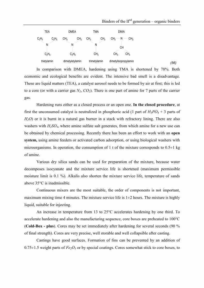
Binders of the IInd
generation – organic binders
N
NC2H5 C2H5
C2H5
TEA
N
DMEA
CH3 CH3
N
TMA
CH3 CH3
CH3C2H5
CH3 CH3
CH
CH3 CH3
DMIA
trietylamin dimetyletylamin trimetylamin dimetylisopropylamin (56)
In comparison with DMEA, hardening using TMA is shortened by 78%. Both
economic and ecological benefits are evident. The intensive bad smell is a disadvantage.
These are liquid matters (TEA), a catalyst aerosol needs to be formed by air at first; this is led
to a core (or with a carrier gas N2, CO2). There is one part of amine for 7 parts of the carrier
gas.
Hardening runs either as a closed process or an open one. In the closed procedure, at
first the unconsumed catalyst is neutralized in phosphoric acid (1 part of H3PO4 + 3 parts of
H2O) or it is burnt in a natural gas burner in a stack with refractory lining. There are also
washers with H2SO4, where amine sulfate salt generates, from which amine for a new use can
be obtained by chemical processing. Recently there has been an effort to work with an open
system, using amine feeders or activated carbon adsorption, or using biological washers with
microorganisms. In operation, the consumption of 1 t of the mixture corresponds to 0.51 kg
of amine.
Various dry silica sands can be used for preparation of the mixture, because water
decomposes isocyanate and the mixture service life is shortened (maximum permissible
moisture limit is 0.1 %). Alkalis also shorten the mixture service life, temperature of sands
above 35°C is inadmissible.
Continuous mixers are the most suitable, the order of components is not important,
maximum mixing time 4 minutes. The mixture service life is 12 hours. The mixture is highly
liquid, suitable for injecting.
An increase in temperature from 13 to 25°C accelerates hardening by one third. To
accelerate hardening and also the manufacturing sequence, core boxes are preheated to 100°C
(Cold-Box - plus). Cores may be set immediately after hardening for several seconds (90 %
of final strength). Cores are very precise, well storable and well collapsible after casting.
Castings have good surfaces. Formation of fins can be prevented by an addition of
0.751.5 weight parts of Fe2O3 or by special coatings. Cores somewhat stick to core boxes, to

Binders of the IInd
generation – organic binders
use a polyurethane insert is the easiest way to withdraw them from the core box. The
production cycle for cores of a weight from several grams up to 130 kg is about 30 sec.
The core hardening is two-fold faster than when using the Croning technology. The
technology has the following disadvantages:
Sorption needs to be used for the excess of amine.
Completely dry silica sand or regenerate needs to be used. Just the presence of 0.1 % of
water in sand means a strong decrease in strength (isocyanate decomposition).
Only alcoholic (more expensive) coatings may be applied (hygiene).
When using water coatings, additional drying is needed (microwave drying).
A limited possibility of a regenerate (mechanical regenerate max. 70 %). Therefore a high
proportion goes away for depositing. Regenerates from other binder systems are not
recommended to use.
Recommended literature for further study
[1.] BROWN, J. Foseco Ferrous Foundryman's Handbook, 11. Vydání, Butterworth-
Heinemann, 2000, 384, ISBN 9780080506791
[2.] BEŇO, J. et.al. Archives of Metallurgy and Materials, 59 (2014), 2, 745-748
[3.] TILCH, W, et al. Giesserei. 2006, 8, s. 12-24. ISSN 0175-1034.
[4.] SPADA, A. Modern Casting, 1998. č. 4, s.45-48.
[5.] GIELISSEN, H. Foundry Trade Journal, February 2002, s.7-11.
[6.] HWANG, J.Y. AFS Transactions, vol. 99, s. 807-815.
[7.] ROSCHIER, M.: Fonderie, tom 33, Nr. 382, 1978, s. 286-288
[8.] TROY, E.C. a kol.: AFS - Transactions, vol. 79, 1971, s. 213-224
[9.] BOENISCH, D.: International Conference 1988, BCIRA, England
[10.] HOFMANN, F.: Technologie der Giessereiformstoffe. Georg Fischer Actiongesellschaft,
Schaffhausen Schweiz, 1965
[11.] LEVELINK, H. G. a kol.: Giesserei 62, 1975, Nr. 5, s. 93-99
[12.] HEINE, R. W.,SCHUMACHER, J. S. ,GREEN, R. A.: AFS Transaction 84, 1976, s. 97-
100
[13.] ANDREWS, J. a kol.: Modern Casting, 90, September 2000, s. 40, 43
[14.] HEADINGTON, F. a kol.. AFS – Transactions 98-01, s. 271-291
[15.] BRÜMMER, G.: Gisserei 87, 2000, Nr. 3, s. 62-68
[16.] KLEIMANN, W.:. Giesserei 85, 1998, Nr. 1, s. 87-90
[17.] BEŇO, J.; et. al.. Archives of foundry engineering. Vol. 11., No. 1., 2011. s. 5-8. ISSN
1897-3310.
[18.] KOLORZ, A., LÖHBERG, K.: Giesserei techn. Wiss. Beihefte, 15, 1963, H. 4, s. 191
[19.] BINDERNAGEL, I., KOLORZ, A.: Giesserei, 51, 1964, s. 729-730
[20.] WÖRMANN, H. ad.: Giessereiforschung, 34, 1982, H. 4, s. 153-159
[21.] BINDERNAGEL, I. a kol.: Giesserei, 61, 1974, č. 8, s. 190-197
[22.] BAIER, J.: Giesserei, No. 12, 1979, s. 480-482
[23.] JELÍNEK, P., BEŇO, J. Archives of Foundry Engineering, April - June 2008. Vol. 8, No.
2, pp. 67 – 70, ISSN 1897-3310
[24.] SACHARUK, L. a kol.: Giessereiforschung 53, 2001, Nr. 3, s. 104/109
[25.] BALINSKI, A.:. Institut Odlewnictwa Kraków, 2000, ISBN 83-911283-5-0

[26.] JELÍNEK, P. – ŠKUTA, R. Acta Metallurgica Slovaca, 4/2002, roč. 8, s. 431/439, ISSN –
1335 – 1532
[27.] HÄNSEL, H.Giesserei, 89, 2002, Nr. 2, s. 74/76
[28.] ILER, R. K.: The Chemistry of Silica, New York, 1968
[29.] FLEMMING, E. a kol.. Giesserei Praxis, 1996, Nr. 9/10, s. 177
[30.] SCHNEIDER, H. a kol.Giessereiforschung, 1991, Nr. 1-2, s. 10
[31.] SVENSON, I. L. a kol. J. Chem. Soc. 1986, t 82, s. 3636
[32.] WARREN, D.The British Foundryman, 1971, Nr. 12, s. 449
[33.] JELÍNEK, P., POLZIN, H. Giesserei Praxis, č. 2, 2003, s. 51/60
[34.] LE SERVE, F. L. - LEMON, P. H.: Modern Casting, 1969, Vol. 56, November 2, s. 146-
150.
[35.] SCHAARSCHMIDT, E. Giessereitechnik, 1971, 17, No.2, s. 43-50
[36.] GARDZIELLA, A. - KWASNIOK, A.. Sonderdruck aus Giesserei, 1988, H. 13
[37.] WOLF, K.: Giesserei – Erfahrungsaustausch, 41, 1997, Nr. 9, s. 391/394
[38.] STÖLZEL, R. a d.: Giesserei 86, 1999, Nr. 6, s. 154/157
[39.] STÖLZEL, R. – GENZLER, Ch.Giesserei – Praxis, 1999, Nr. 12, s. 568
[40.] LEDEGOURDIE, G. a kol.: Foundry Trade Journal 1997, october, s. 434
[41.] ADAMS, P.Litějnoje proizvodstvo, 1999, No. 2, s. 20
[42.] SCHREY, A. a d.Giesserei 88, 2001, Nr. 6, s. 51/56
[43.] JELÍNEK, P.; DUDA, J.; MIKŠOVSKÝ, F.; BEŇO, J. Archives of Foundry Engineering.
Vol. 12 (2012), 1/1012. p. 47-52