VŠB - Technical University of Ostrava Faculty of Metallurgy and Materials...
63
Pokyny ke studiu 1 VŠB - Technical University of Ostrava Faculty of Metallurgy and Materials Engineering TECHNOLOGICAL DESIGN AND PREPARATION OF CASTING PRODUCTION (e-learning) Design Technologicity Lecture notes / case studies / tests Jiří Hampl Ostrava 2016 Reviewer: prof. Ing. Tomáš Elbel, CSc.
Transcript of VŠB - Technical University of Ostrava Faculty of Metallurgy and Materials...
Pokyny ke studiu
1
VŠB - Technical University of Ostrava
Faculty of Metallurgy and Materials Engineering
TECHNOLOGICAL DESIGN AND
PREPARATION OF CASTING
PRODUCTION (e-learning) Design Technologicity
Lecture notes / case studies / tests
Jiří Hampl
Ostrava 2016
Reviewer: prof. Ing. Tomáš Elbel, CSc.
Title: Technological Design and Preparation of Casting Production
Author: doc. Ing. Jiří Hampl, Ph. D.
Edition: first, 2016
Number of pages: 62
Educational materials for the field of study Modern Metallurgical Technologies (Metallurgical
Engineering study programme) of the follow-up study at the Faculty of Metallurgy and Materials
Engineering Proof-reading: not performed
Intended for the project:
The Education for Competitiveness Operational Programme (ECOP)
Faculty of Metallurgy and Materials Engineering VŠB - Technical University of Ostrava
Number: CZ.1.07/2.2.00/28.0304
Realization: VŠB - Technical University of Ostrava
The project is co-financed with ESF funds and from the state budget of the Czech Republic
© doc. Ing. Jiří Hampl, Ph. D.
© VŠB - Technical University of Ostrava
Table of contents
TECHNOLOGICAL DESIGN AND PREPARATION OF CASTING
PRODUCTION.............................................................................................. 1
STUDY REGULATIONS ................................................................................... 4
TECHNOLOGICAL DESIGN AND PREPARATION OF CASTING
PRODUCTION.............................................................................................. 4
INTRODUCTION ............................................................................................... 5
1 BASIC TERMS AND AIMS OF CASTING TECHNOLOGICAL
DESIGN .......................................................................................................... 7 1.1 Basic terms .............................................................................................................................. 7
Technological design of castings (TDC) ......................................................................................... 7 Technological procedure of production (TPP) of castings .............................................................. 8
2 PRINCIPLES OF CASTING DESIGN IN TERMS OF MOLD
MAKING ...................................................................................................... 16 Principles of the technological design of castings cast into sand moulds ......................................... 16
3 PRINCIPLES OF CASTING CONSTRUCTION WITH REGARD TO
PRE-CASTING OF CAVITIES USING CORES .................................... 25 Core making methods ........................................................................................................................ 26
4 PRINCIPLES OF CASTING DESIGN IN TERMS OF DIRECTIONAL
SOLIDIFICATION ..................................................................................... 36 4.1 Elimination of a size of thermal nodes .................................................................................. 42
5 PRINCIPLES OF CASTING DESIGN WITH REGARD TO STRESS
IN CASTINGS ............................................................................................. 47
6 PRINCIPLES OF A CASTING DESIGN IN TERMS OF FETTLING
AND FINISHING ........................................................................................ 58
STUDY REGULATIONS
Technological Design and Preparation of Casting Production
You have obtained an educational packet including integrated lecture notes for the combined study
comprising also study regulations.
The subject “Technological Design and Preparation of Casting Production” is intended for the 3rd
semester of the follow-up study of the branch Modern Metallurgical Technologies.
Prerequisites
Graduation from the following subjects is a prerequisite for the study of this subject: Technology and
Theory of Metalcasting and Metallurgy of Foundry Alloys
The objectives of the subject and outputs from the education
The aim of the subject is to introduce students to theoretical and practical knowledge on
technological design and technical preparation of casting production. Emphasis is placed on
application of the acquired knowledge in design and technology of castings, ensuring all of their
functions as well as maximum cost-effectiveness of the manufacture.
After studying the subject, a student should
- know the principles of technological design of castings (TDC)
- know basic procedures of the preparation of casting production (PCP)
- be able to apply the principles of TDC and PCP in the casting manufacturing process
For whom the subject is intended
The subject falls within the follow-up study of the field of study Modern Metallurgical Technologies
of the study programme Metallurgical Engineering, but it can also be studied by applicants from any
other branch, on condition of having met the demanded prerequisites.
Recommended procedure for studying each chapter
The lecture notes divided to chapters need to be read-through as a whole at first. Only after that it is
advisable to begin to study the particular chapters.
A way to communicate with lecturers
You can contact the lecturer through e-mail: [email protected] or by telephone:
+420 597 324 206.

INTRODUCTION
The subject “Technological Design and Preparation of Casting Production” covers principles of
the casting design in term of their manufacturability by foundry technologies. A degree of
technological design of a casting: A high degree means a condition, when a casting can be
manufactured at meeting all technical and economic parameters. On the contrary, a low degree
means that a casting can be manufactured under the given conditions only with difficulties - e.g.
an unsuitable design (material) of a casting or improper manufacturing conditions in the foundry
shop for the given casting. This usually results in increased costs caused for example by high
nonconformance (wastage) of the production.
A properly designed “foundry construction“ gives a presupposition for high usable properties as
well as cost-effective manufacture of castings. On the contrary, a design not respecting the applied
foundry technology (non-technological design) typically leads to costly production and only
difficult-to-meet requirements on casting properties.
As a matter of fact, castings can be manufactured from a broad range of foundry alloys without
any limitation in shape. An optimal design is usually a compromise between technical
requirements for a function, shape, strength, quality, service life, reliability on one side and a
technological potential of a foundry shop and economy of production on the other side.
Obr. 1 Flowchart of a good and bad (below) cooperation of a designer and technologist on
preparation of a casting manufacture
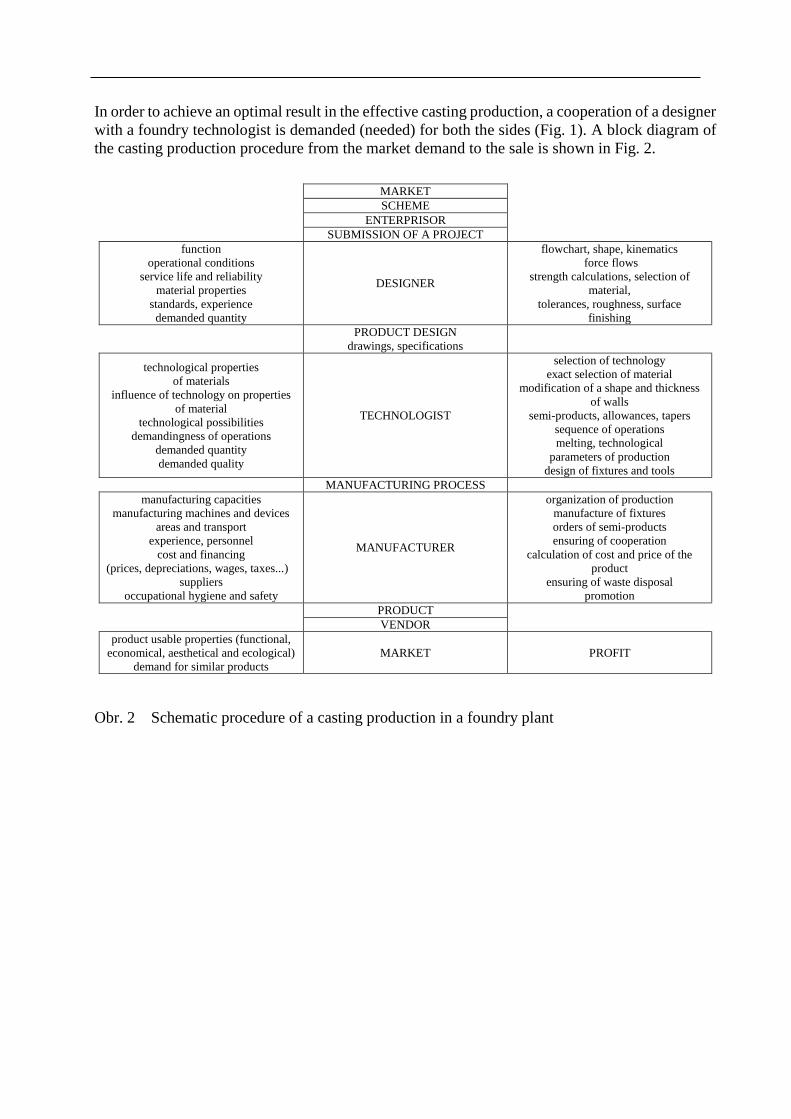
In order to achieve an optimal result in the effective casting production, a cooperation of a designer
with a foundry technologist is demanded (needed) for both the sides (Fig. 1). A block diagram of
the casting production procedure from the market demand to the sale is shown in Fig. 2.
MARKET
SCHEME
ENTERPRISOR
SUBMISSION OF A PROJECT
function
operational conditions
service life and reliability
material properties
standards, experience
demanded quantity
DESIGNER
flowchart, shape, kinematics
force flows
strength calculations, selection of
material,
tolerances, roughness, surface
finishing
PRODUCT DESIGN
drawings, specifications
technological properties
of materials
influence of technology on properties
of material
technological possibilities
demandingness of operations
demanded quantity
demanded quality
TECHNOLOGIST
selection of technology
exact selection of material
modification of a shape and thickness
of walls
semi-products, allowances, tapers
sequence of operations
melting, technological
parameters of production
design of fixtures and tools
MANUFACTURING PROCESS
manufacturing capacities
manufacturing machines and devices
areas and transport
experience, personnel
cost and financing
(prices, depreciations, wages, taxes...)
suppliers
occupational hygiene and safety
MANUFACTURER
organization of production
manufacture of fixtures
orders of semi-products
ensuring of cooperation
calculation of cost and price of the
product
ensuring of waste disposal
promotion
PRODUCT
VENDOR
product usable properties (functional,
economical, aesthetical and ecological)
demand for similar products
MARKET PROFIT
Obr. 2 Schematic procedure of a casting production in a foundry plant
1 BASIC TERMS AND AIMS OF CASTING
TECHNOLOGICAL DESIGN
Subchapters:
Basic terms
Objectives
Time needed for the study: individual
Objective: After studying this chapter a student will be able to:
Define basic terms of casting technological design
Define a degree of technological design of a casting
Design an optimal casting construction in term of the applied foundry technology
Lecture
1.1 Basic terms
Technological designing of castings (TDC)
The technological designing of castings (or technologicity) is a broad term involving all
requirements for properties and functions of a designed casting while respecting conditions of its
manufacture. The manufacturing process from an engineering design (deaft), over the manufacture
of a gated pattern, casting, to fettling and finishing, is influenced above all by a designer of a
component – a casting.
A designer designs shapes, materials, dimensions, surface quality and the casting precision. The
designer through his/her design predetermines meeting of all the required parameters of the casting
and mostly also its good or difficult manufacturability, i.e. the technological degree.
General principles of the technological designing of castings
At the beginning of the process (technical preparation) is always a design of the designer expressed
by a drawing documentation or 3D data of a machine component. A design of an optimal
construction of a casting is a complicated process requiring cooperation of a lot of specialists,
above all a designer and a foundry technologist.
In this (preproduction) phase of the design, specific aspects of the foundry technology should be
considered:
- Possibility to create even highly complex shapes of a casting surface including pre-casting
of holes, cavities and reinforcing ribs – without a noticeable increase in production costs
- Application of a broad range of foundry alloys for castings
- Possibility to influence structures of castings in as-cast condition as well as by heat
treatment
- Combination of various materials, such as casting of steel inserts of cylinders into engine
blocks of cast iron
- Casting of metallurgically connected material layers (e.g. multilayer centrifugal castings
of rolls for rolling mill stands etc.)
In principle, it is not recommended to imitate shapes of forgings, weldments or parts manufactured
from semi-products by machining, which do not allow full utilization of foundry technology
advantages. Constructions imitated this way cause troubles during casting and solidification and
typically also impaired properties of castings in operation. For example, in the past it was an
increased failure rate of crankshaft castings (compared to forgings), which was removed by a
properly designed construction respecting the foundry technology. At present, crankshafts are
commonly cast with comparable parameters as for forgings, but at lower production cost.
For a foundry casting design, the most important is a selection of geometry of main functional
parts, which adapt to maximum rigidity and minimum consumption of the casting material, while
achieving maximum cost-effectiveness.
A shape of a future casting is subsequently modified according to the proposed foundry technology
of manufacturing, i.e. a mould type (expendable mould, permanent mould), the casting method –
gravitational casting, pressure casting, precision casting etc.
The aim is to ensure a maximal inner homogeneity of the casting through a proper design.
Principles of the directional solidification including a correct function of risers in order to reduce
a risk of inner defects (shrinkages) in the casting are applied.
Requirements for casting properties are highly diverse, many times antagonistic. Achieving high
strength (toughness) need not always to be the most important demand. Many times a shape
complexity and maximum surface area are preferred to high mechanical properties (radiators,
boiler fuel cells, heat exchangers) or pre-casting of complicated inner cavities (engine heads and
blocks, hydraulic distributions).
So, the technological design is such a structural embodiment of a casting, which ensures all its
required parameters, e.g. mechanical properties, service life and reliability, to be ensured at
maximum production cost-effectiveness.
Technological procedure of production (TPP) of castings
A technologist designs a procedure of a casting production on the basis of the technical
documentation of a component (a technical drawing, 3D data). When designing the TPP, technical
and economic conditions of the production are considered, typically adapted to conditions in a
particular foundry shop.
The technology of a casting manufacture (specified by material and weight) is bound to production
conditions in the foundry plant, i.e. a furnace size, a type of moulding line, types of moulding
materials, a level of automatization, a kind of production (single-piece production, small-lot
production, batch production, large-scale production).
Basic aims of casting technological designing and TPP
a) to ensure the highest quality, i.e. minimization of production risks (nonconformance) at
minimum work expenditure and
b) observance of required (standardized) properties
c) optimal – acceptable costs while ensuring required casting properties, i.e. the optimal quality
d) at minimum work expenditure (minimization of risks in term of nonconformance - wastage
of production)
Principles of the technological designing of castings
1. A casting shape must respect the foundry technology at a maximum extent, i.e. a uniform
wall thickness, smooth tapers, rounding
2. An alloy with an adequate structure, mechanical and physical properties
3. Good metalcasting properties of the chosen material-alloy (low tendency to shrinkage,
fluidity)
4. To prevent defects by respecting the foundry technology – mainly the principles of the
directional solidification
5. Adequate demands for precision – minimization of technological allowances
6. Precise and clearly defined demands for quality - acceptance terms of castings
7. Fast and non-costly technical preparation of production (TPP) – application of the
simulation of solidification and Rapid Prototyping
8. Application of normalization and typification of the whole casting production process
9. Selection of an applicable type of documentation (3D data)
10. Maximal utilization of manufacturing capacities of the foundry plant (existing machinery)
11. Minimization of production and overhead costs
12. Application of mechanization and automatization of production
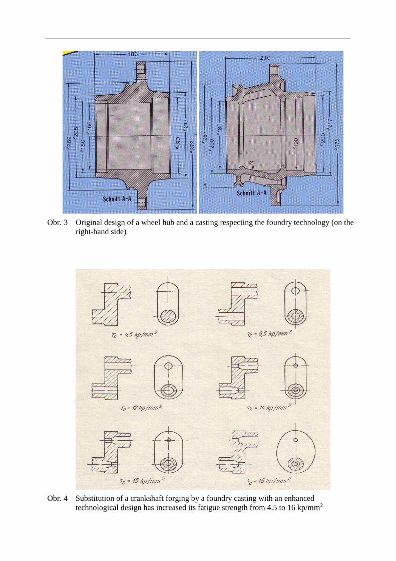
Obr. 3 Original design of a wheel hub and a casting respecting the foundry technology (on the
right-hand side)
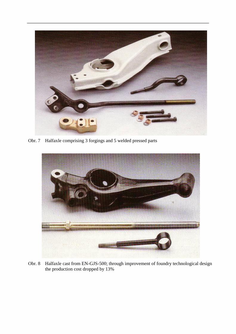
Obr. 4 Substitution of a crankshaft forging by a foundry casting with an enhanced
technological design has increased its fatigue strength from 4.5 to 16 kp/mm2

Obr. 5 Original construction of a ship motor bracket welded from 5 parts
Obr. 6 Casting of a bracket with by 50% higher fatigue limit and 30% lower weight as a
substitute for the original welded construction
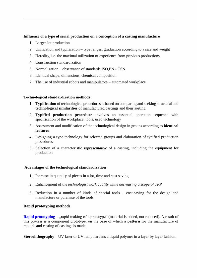
Obr. 7 Halfaxle comprising 3 forgings and 5 welded pressed parts
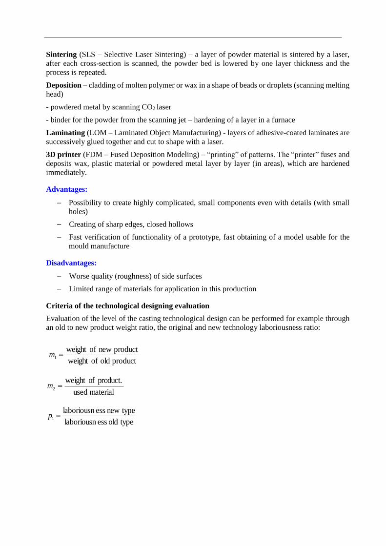
Obr. 8 Halfaxle cast from EN-GJS-500; through improvement of foundry technological design
the production cost dropped by 13%
Influence of a type of serial production on a conception of a casting manufacture
1. Larger-lot production
2. Unification and typification – type ranges, graduation according to a size and weight
3. Heredity, i.e. the maximal utilization of experience from previous productions
4. Construction standardization
5. Normalization – observance of standards ISO,EN - ČSN
6. Identical shape, dimensions, chemical composition
7. The use of industrial robots and manipulators – automated workplace
Technological standardization methods
1. Typification of technological procedures is based on comparing and seeking structural and
technological similarities of manufactured castings and their sorting
2. Typified production procedure involves an essential operation sequence with
specification of the workplace, tools, used technology
3. Assessment and modification of the technological design in groups according to identical
features
4. Designing a type technology for selected groups and elaboration of typified production
procedures
5. Selection of a characteristic representative of a casting, including the equipment for
production
Advantages of the technological standardization
1. Increase in quantity of pieces in a lot, time and cost saving
2. Enhancement of the technologist work quality while decreasing a scope of TPP
3. Reduction in a number of kinds of special tools – cost-saving for the design and
manufacture or purchase of the tools
Rapid prototyping methods
Rapid prototyping – „rapid making of a prototype” (material is added, not reduced). A result of
this process is a component prototype, on the base of which a pattern for the manufacture of
moulds and casting of castings is made.
Stereolithography – UV laser or UV lamp hardens a liquid polymer in a layer by layer fashion.
Sintering (SLS – Selective Laser Sintering) – a layer of powder material is sintered by a laser,
after each cross-section is scanned, the powder bed is lowered by one layer thickness and the
process is repeated.
Deposition – cladding of molten polymer or wax in a shape of beads or droplets (scanning melting
head)
- powdered metal by scanning CO2 laser
- binder for the powder from the scanning jet – hardening of a layer in a furnace
Laminating (LOM – Laminated Object Manufacturing) - layers of adhesive-coated laminates are
successively glued together and cut to shape with a laser.
3D printer (FDM – Fused Deposition Modeling) – “printing” of patterns. The “printer” fuses and
deposits wax, plastic material or powdered metal layer by layer (in areas), which are hardened
immediately.
Advantages:
Possibility to create highly complicated, small components even with details (with small
holes)
Creating of sharp edges, closed hollows
Fast verification of functionality of a prototype, fast obtaining of a model usable for the
mould manufacture
Disadvantages:
Worse quality (roughness) of side surfaces
Limited range of materials for application in this production
Criteria of the technological designing evaluation
Evaluation of the level of the casting technological design can be performed for example through
an old to new product weight ratio, the original and new technology laboriousness ratio:
product old ofweight
product new ofweight 1 m
material used
product. ofweight 2 m
typeold esslaboriousn
typenew esslaboriousn1 p
Methods of the technical preparation of production - TPP
Sequential engineering
The design preparation, technological preparation and production are done in stages one after
another. After one stage is tested and completed, it is left alone and everything is concentrated
on the next task.
Concurrent (simultaneous) engineering
It is used today; the design preparation, technological preparation and production operate at
the same time - simultaneously, thus saving a half of the original time. More construction
variants are tackled at the same time. The particular professions of technology, design and
economy engineers occur in the same time frame.
Summary of terms of this chapter (subchapters)
1. Technological design of castings
2. Basic aims of the technological design of castings
3. Basic aims of the technical preparation of castings
Questions to the topic
1. What are advantages of foundry technology in term of complexity of components?
2. What is a structure of castings in term of macro- and microstructure?
3. Describe principles of the technological production of castings.
4. Explain methods of technological standardization.
5. How can a degree of technological design of castings be determined?
2 PRINCIPLES OF CASTING DESIGN IN TERMS OF MOLD
MAKING
Subchapters:
Basic terms
Objectives
Time needed for the study: individual
Objective: After studying this chapter a student will be able to:
Define principles of a design of castings cast into sand moulds
Design a way of setting a casting in a mould
Design a parting plane (joint) of a mould
Lecture
Principles of the technological designing of castings cast into sand moulds
If possible, a casting should be a connection of simple geometrical bodies with prevailing
planar and cylindrical areas
Where a shape complexity is necessary, obtaining of a required shape without a need of
machining is preferred (parts of pumps, turbine blades, exhaust pipelines etc.)
A casting design is based on a presupposed method of mould making and the used casting
technology
A casting pattern should have as few parting surfaces, free parts, protrusions without sharp
edges, recesses and corners as possible
Parting surfaces of a casting and mould should be planar, if possible
A casting should have adequately large tapers allowing easy withdrawal of a pattern from
a mould
A casting should not have big differences in wall thicknesses, which could support
occurrence of shrinkages (a need to use risers, chills)
To ensure satisfactory molten metal flow rate during filling the mould
Wall thicknesses should increase towards risers
To use gradual transitions, roundings, in case of need reinforcing ribs to prevent occurrence
of hot and cold cracks in wall joints
Large thicknesses and local accumulation of metal increase a tendency for occurrence of
internal stresses and shrinkages
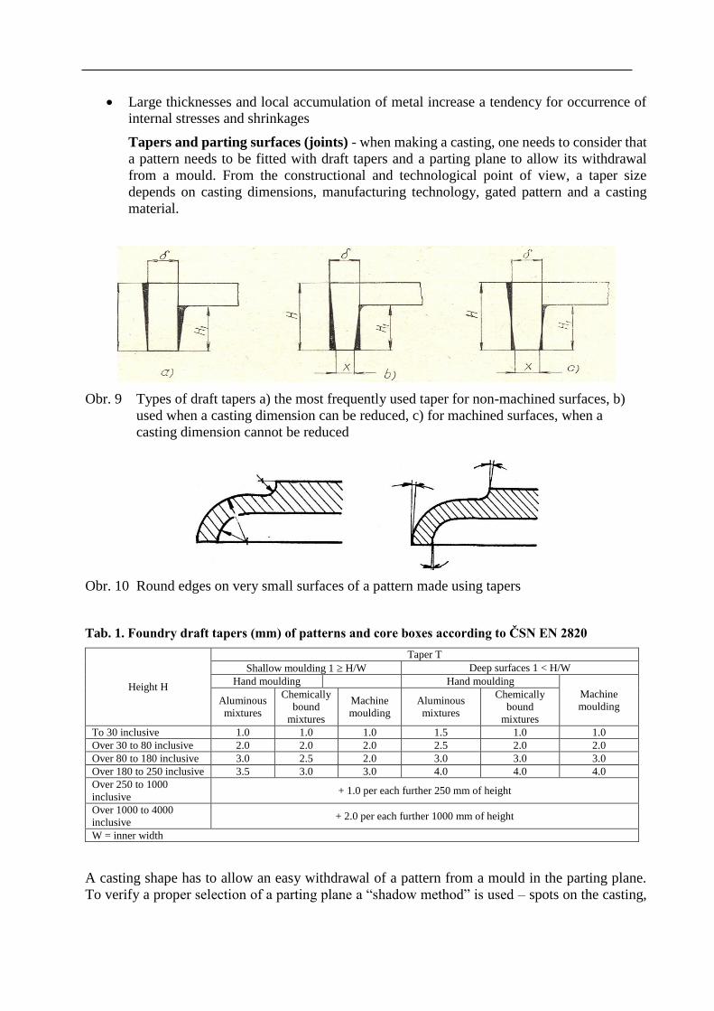
Tapers and parting surfaces (joints) - when making a casting, one needs to consider that
a pattern needs to be fitted with draft tapers and a parting plane to allow its withdrawal
from a mould. From the constructional and technological point of view, a taper size
depends on casting dimensions, manufacturing technology, gated pattern and a casting
material.
Obr. 9 Types of draft tapers a) the most frequently used taper for non-machined surfaces, b)
used when a casting dimension can be reduced, c) for machined surfaces, when a
casting dimension cannot be reduced
Obr. 10 Round edges on very small surfaces of a pattern made using tapers
Tab. 1. Foundry draft tapers (mm) of patterns and core boxes according to ČSN EN 2820
Height H
Taper T
Shallow moulding 1 H/W Deep surfaces 1 < H/W
Hand moulding Hand moulding
Machine
moulding Aluminous
mixtures
Chemically
bound
mixtures
Machine
moulding
Aluminous
mixtures
Chemically
bound
mixtures
To 30 inclusive 1.0 1.0 1.0 1.5 1.0 1.0
Over 30 to 80 inclusive 2.0 2.0 2.0 2.5 2.0 2.0
Over 80 to 180 inclusive 3.0 2.5 2.0 3.0 3.0 3.0
Over 180 to 250 inclusive 3.5 3.0 3.0 4.0 4.0 4.0
Over 250 to 1000
inclusive + 1.0 per each further 250 mm of height
Over 1000 to 4000
inclusive + 2.0 per each further 1000 mm of height
W = inner width
A casting shape has to allow an easy withdrawal of a pattern from a mould in the parting plane.
To verify a proper selection of a parting plane a “shadow method” is used – spots on the casting,
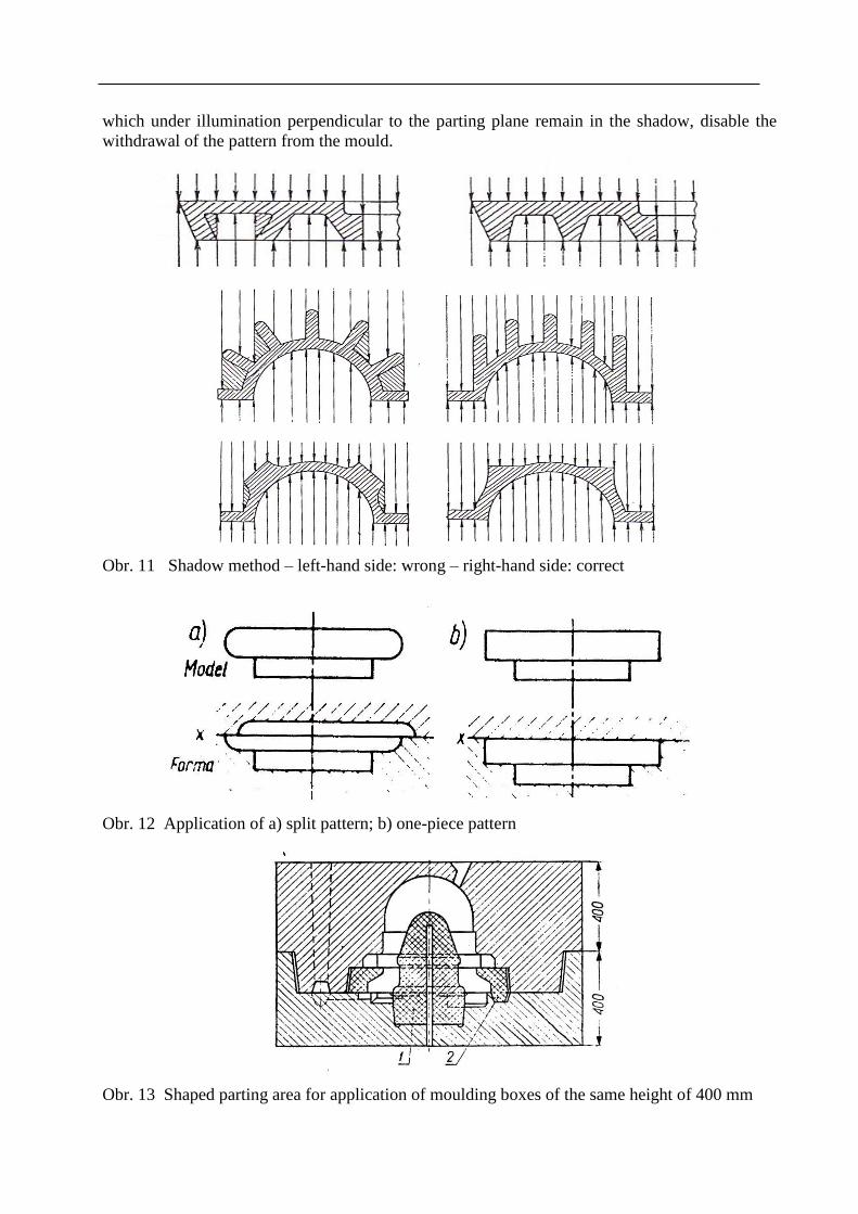
which under illumination perpendicular to the parting plane remain in the shadow, disable the
withdrawal of the pattern from the mould.
Obr. 11 Shadow method – left-hand side: wrong – right-hand side: correct
Obr. 12 Application of a) split pattern; b) one-piece pattern
Obr. 13 Shaped parting area for application of moulding boxes of the same height of 400 mm
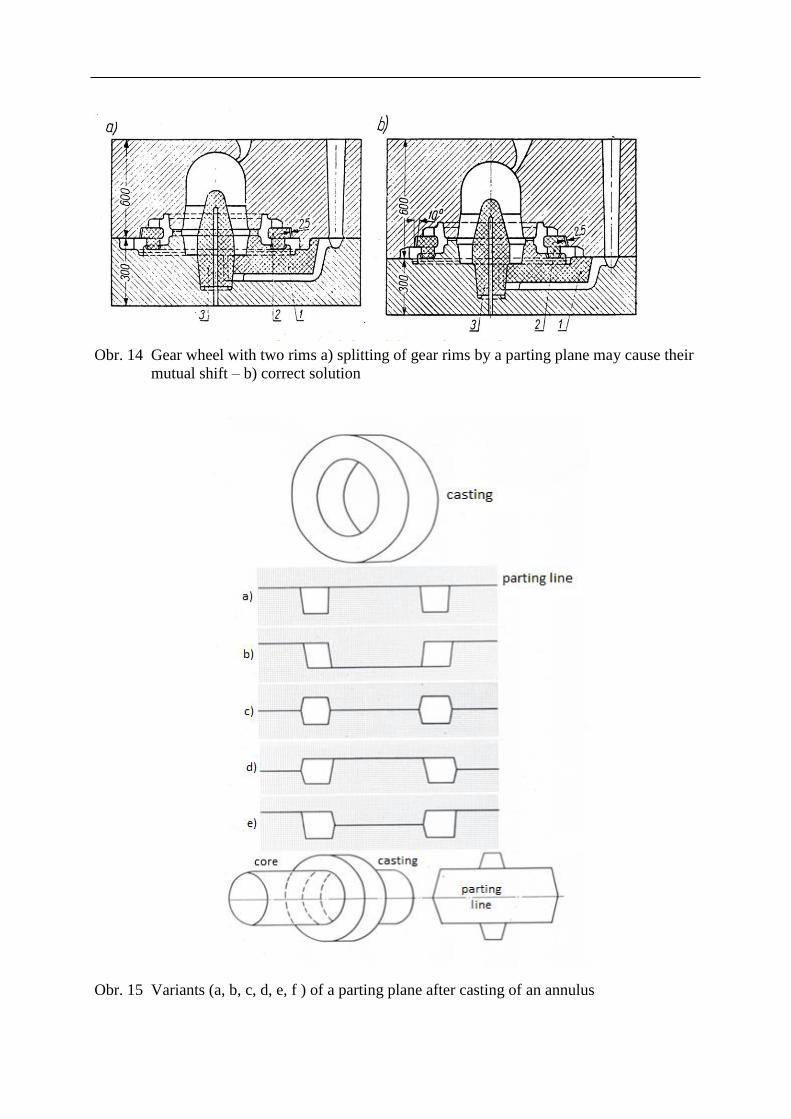
Obr. 14 Gear wheel with two rims a) splitting of gear rims by a parting plane may cause their
mutual shift – b) correct solution
Obr. 15 Variants (a, b, c, d, e, f ) of a parting plane after casting of an annulus
A selection of the parting plane typically depends on more factors being usually a case of
compromise.
a) the parting plane does not influence concentricity of casting walls
b) creates parallel walls with a standard taper on the circumference and also inside the casting
cavity
c) a need to ensure proper closing of both halves of the mould, so that a casting cross-joint does
not occur
d, e) the solution has the lowest demands for subsequent processing, which is applicable for
difficult-to-machine materials; a risk of a cross-joint of the mould is here, too
f) without tapers in a hole and along the casting circumference, core prints for seating a core
need to be used
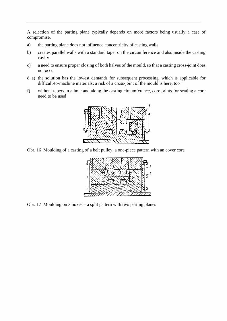
Obr. 16 Moulding of a casting of a belt pulley, a one-piece pattern with an cover core
Obr. 17 Moulding on 3 boxes – a split pattern with two parting planes
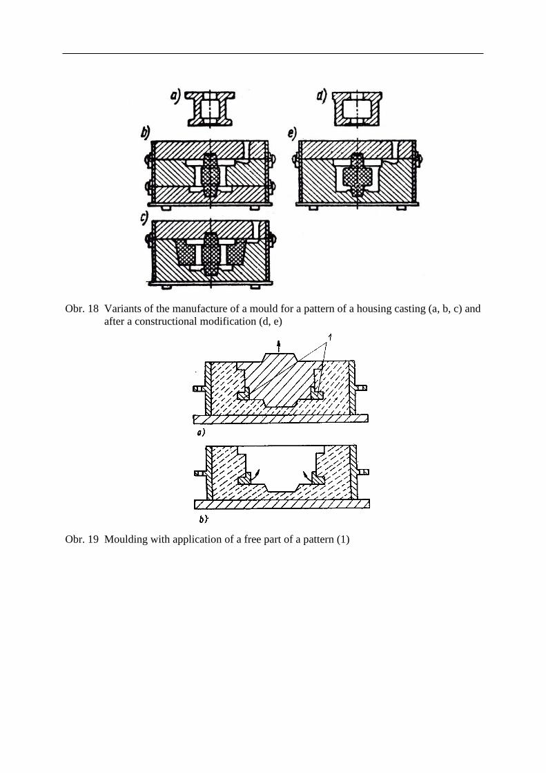
Obr. 18 Variants of the manufacture of a mould for a pattern of a housing casting (a, b, c) and
after a constructional modification (d, e)
Obr. 19 Moulding with application of a free part of a pattern (1)
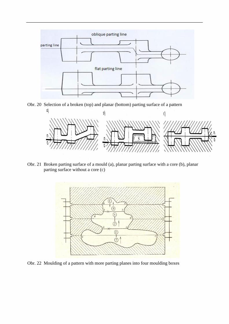
Obr. 20 Selection of a broken (top) and planar (bottom) parting surface of a pattern
Obr. 21 Broken parting surface of a mould (a), planar parting surface with a core (b), planar
parting surface without a core (c)
Obr. 22 Moulding of a pattern with more parting planes into four moulding boxes
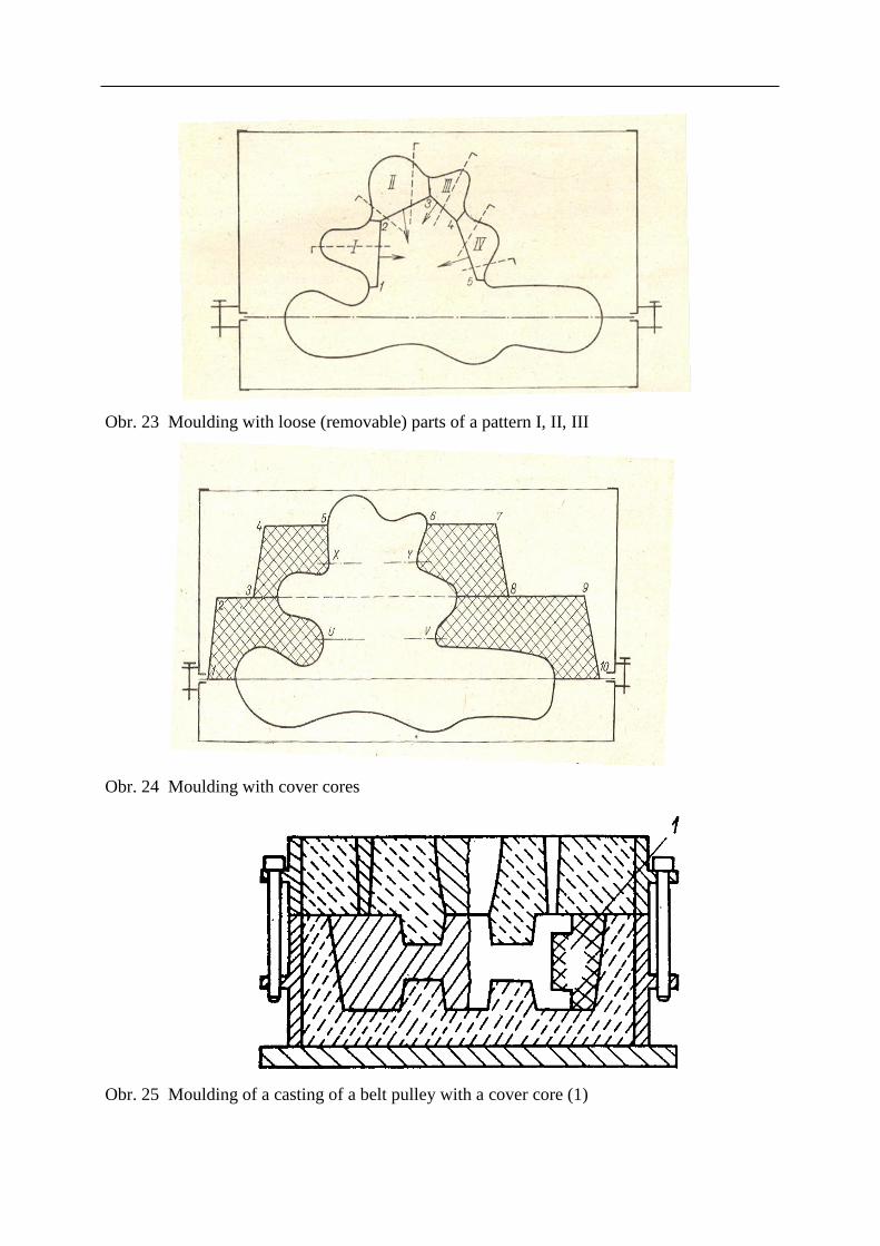
Obr. 23 Moulding with loose (removable) parts of a pattern I, II, III
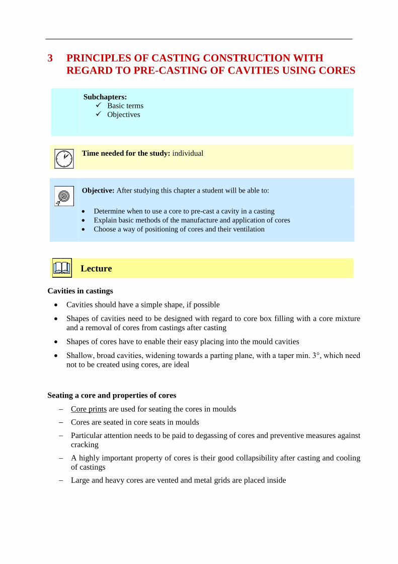
Obr. 24 Moulding with cover cores
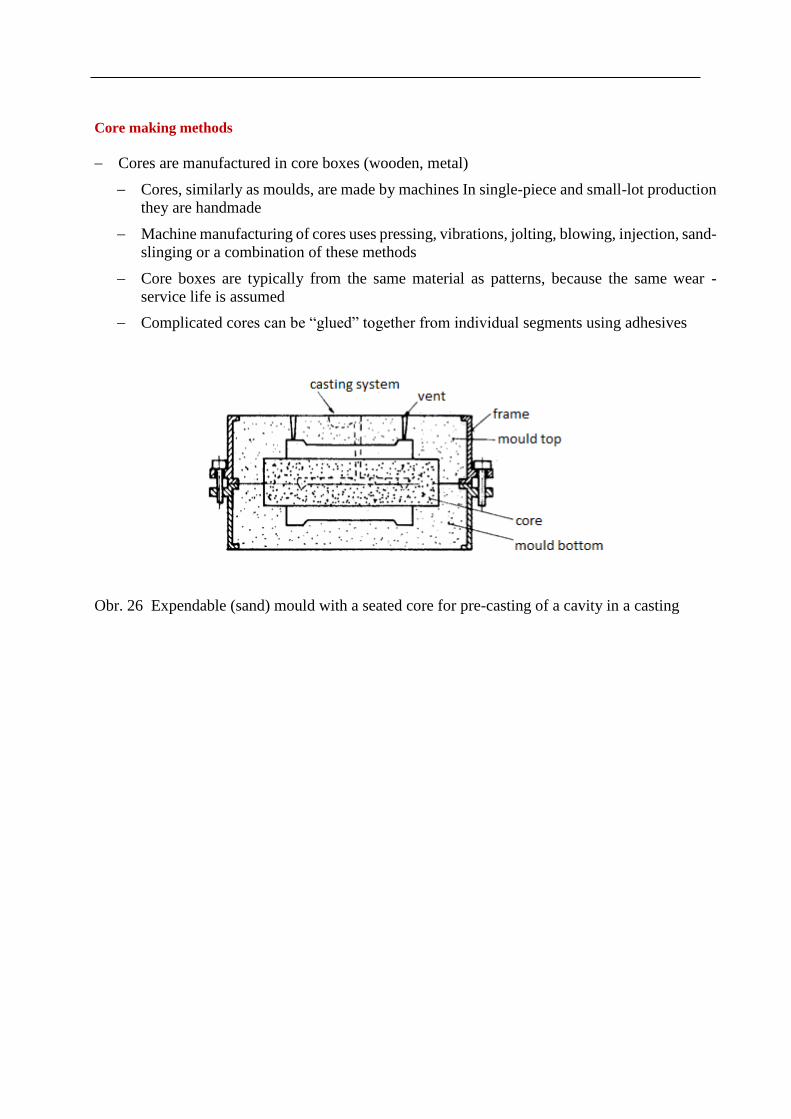
Obr. 25 Moulding of a casting of a belt pulley with a cover core (1)

Summary of terms of this chapter (subchapters)
1. Position of a casting in a mould
2. Parting plane, tapers and technological allowances
3. Core and cover core
Questions to the topic
1. What are the criteria for a selection of a position of a casting in a mould?
2. What are the criteria for a selection of a value of technological allowances?
3. What is a loose piece of a pattern and when can be used?
Recommended literature for further study
3 PRINCIPLES OF CASTING CONSTRUCTION WITH
REGARD TO PRE-CASTING OF CAVITIES USING CORES
Subchapters:
Basic terms
Objectives
Time needed for the study: individual
Objective: After studying this chapter a student will be able to:
Determine when to use a core to pre-cast a cavity in a casting
Explain basic methods of the manufacture and application of cores
Choose a way of positioning of cores and their ventilation
Lecture
Cavities in castings
Cavities should have a simple shape, if possible
Shapes of cavities need to be designed with regard to core box filling with a core mixture
and a removal of cores from castings after casting
Shapes of cores have to enable their easy placing into the mould cavities
Shallow, broad cavities, widening towards a parting plane, with a taper min. 3°, which need
not to be created using cores, are ideal
Seating a core and properties of cores
Core prints are used for seating the cores in moulds
Cores are seated in core seats in moulds
Particular attention needs to be paid to degassing of cores and preventive measures against
cracking
A highly important property of cores is their good collapsibility after casting and cooling
of castings
Large and heavy cores are vented and metal grids are placed inside
Core making methods
Cores are manufactured in core boxes (wooden, metal)
Cores, similarly as moulds, are made by machines In single-piece and small-lot production
they are handmade
Machine manufacturing of cores uses pressing, vibrations, jolting, blowing, injection, sand-
slinging or a combination of these methods
Core boxes are typically from the same material as patterns, because the same wear -
service life is assumed
Complicated cores can be “glued” together from individual segments using adhesives
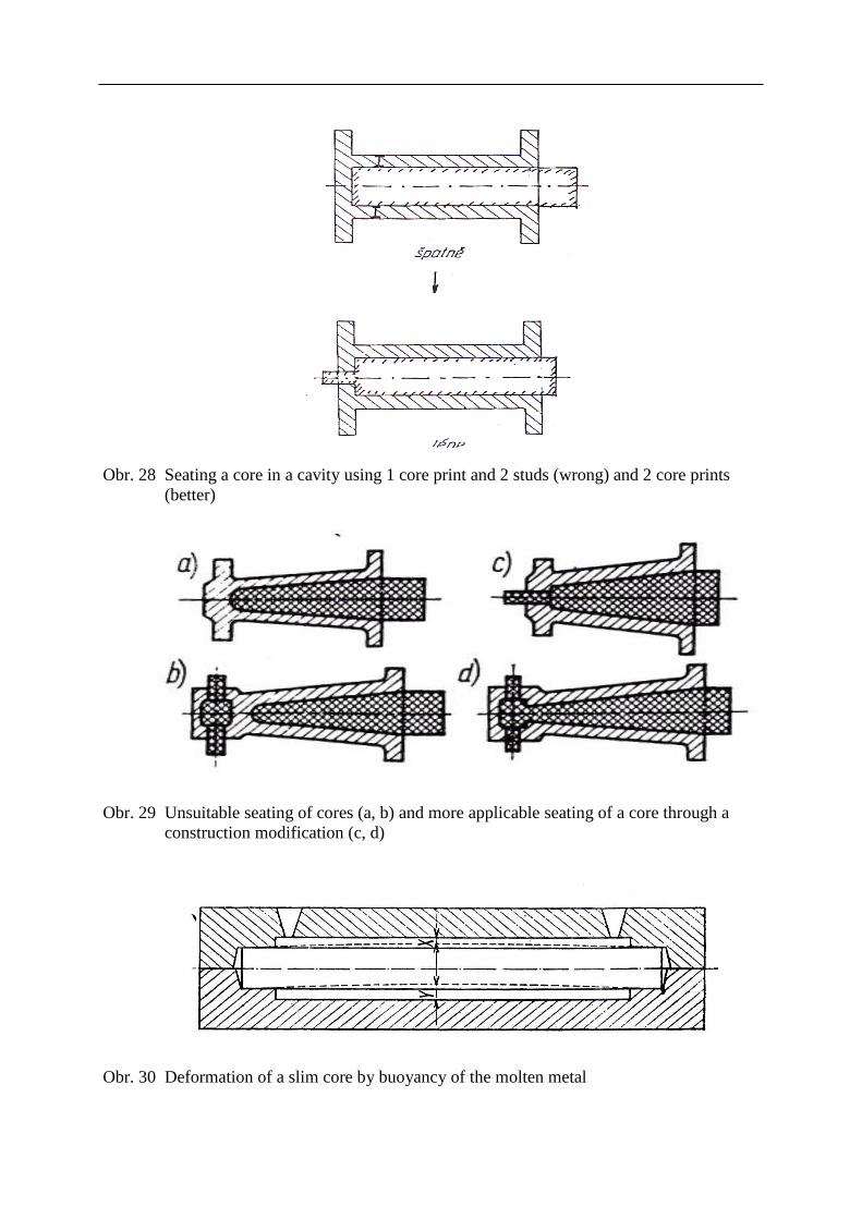
Obr. 26 Expendable (sand) mould with a seated core for pre-casting of a cavity in a casting

Obr. 27 Mould (4,5) with a seated core (3) and a casting (B,1) with a gate (A,6) and an overflow
(C,7)
Obr. 28 Seating a core in a cavity using 1 core print and 2 studs (wrong) and 2 core prints
(better)
Obr. 29 Unsuitable seating of cores (a, b) and more applicable seating of a core through a
construction modification (c, d)
Obr. 30 Deformation of a slim core by buoyancy of the molten metal

The use of cores and their processing
Cores are mostly used for creating inner cavities (shapes) in castings – ‘true’ cores
Cores can be also used for creating an outer surface of a casting, the so-called cover cores
By decomposition of binders and evaporation of moisture during casting, gases and
vapours generate inside the core, concentrating in the centre of the core and being led off
the mould. Whistlers and vents are used for this purpose, leading to the core print part of
the core
A final core manufacturing procedure is usually application of a dressing
Rules for not pre-casting holes
Holes with dimensions with precise tolerances
Holes which can be finished by drilling
Holes the pre-casting of which would endanger a casting homogeneity (misrun, cross-
section reduction)
Holes the pre-casting of which would dramatically increase costs for cleaning
Rules for sizes of pre-cast holes
Round cylindrical holes in steel castings can be pre-cast for d≥20 mm
It also depends on a wall thickness of a casting (s) in which the hole is placed. The limit
dimensions are recommended:
For straight-through holes: d < 2s ; l < d 2s < d < 3s; l<< 3d
For closed holes: d < 2s l < 0.5d 2s < d < 3s l << 2d
A length of elongated horizontal holes of small cross-sections is limited with regard to
buoyancy
For thin-walled castings from heavy alloys l < 10d; from lightweight alloys l < 12d
For thick-walled castings from heavy alloys l < 3d; from lightweight alloys l < 3d
For closed holes these values are reduced to a half or down to a third
Tab. 2. Minimal diameters of pre-cast holes for different materials and types of moulds
Casting material
Sand moulds Metal moulds Ceramic moulds
Exceptionally
Commonly
small
castings
Commonly
large castings
Gravity
casting
Pressure
casting Exceptionally
Comm
only
Steel 15 - 20 50 80 – 100 1.5 2.5
Graphite cast irons 10 – 15 20 40 15
Malleable cast iron 5 10 30
Cu alloys 12 20 30 12 2.3 – 3
Al alloys 5 20 30 6 - 12 1 – 1.5
Mg alloys 5 20 30 6 - 8 1 – 1.5
Zn alloys 5 20 30 6 10
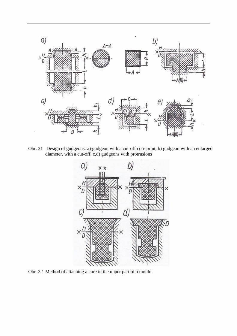
Obr. 31 Design of gudgeons: a) gudgeon with a cut-off core print, b) gudgeon with an enlarged
diameter, with a cut-off, c,d) gudgeons with protrusions
Obr. 32 Method of attaching a core in the upper part of a mould
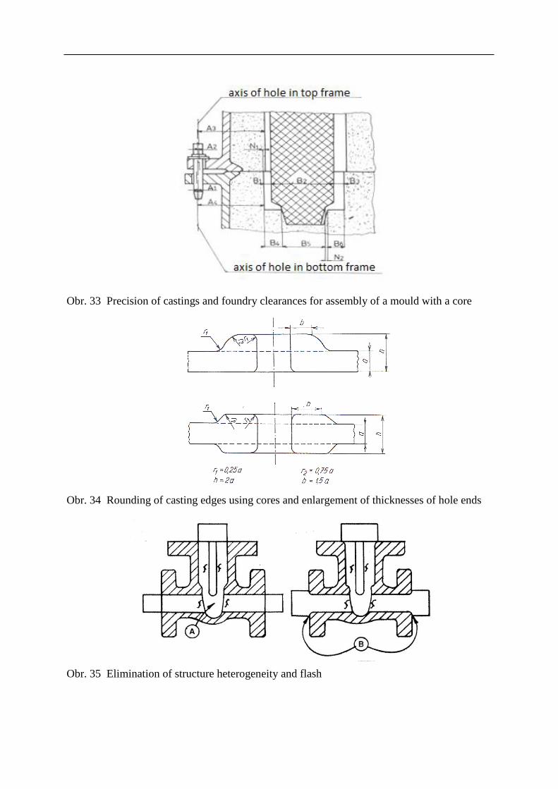
Obr. 33 Precision of castings and foundry clearances for assembly of a mould with a core
Obr. 34 Rounding of casting edges using cores and enlargement of thicknesses of hole ends
Obr. 35 Elimination of structure heterogeneity and flash
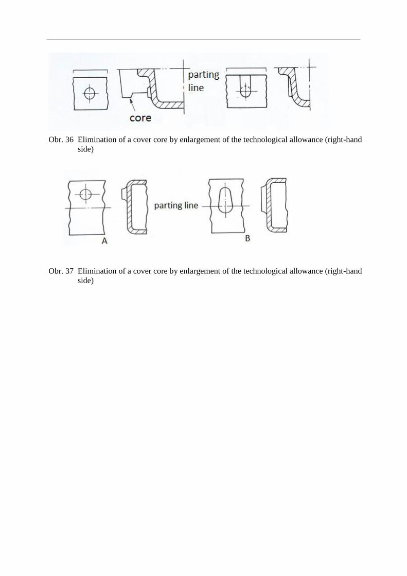
Obr. 36 Elimination of a cover core by enlargement of the technological allowance (right-hand
side)
Obr. 37 Elimination of a cover core by enlargement of the technological allowance (right-hand
side)
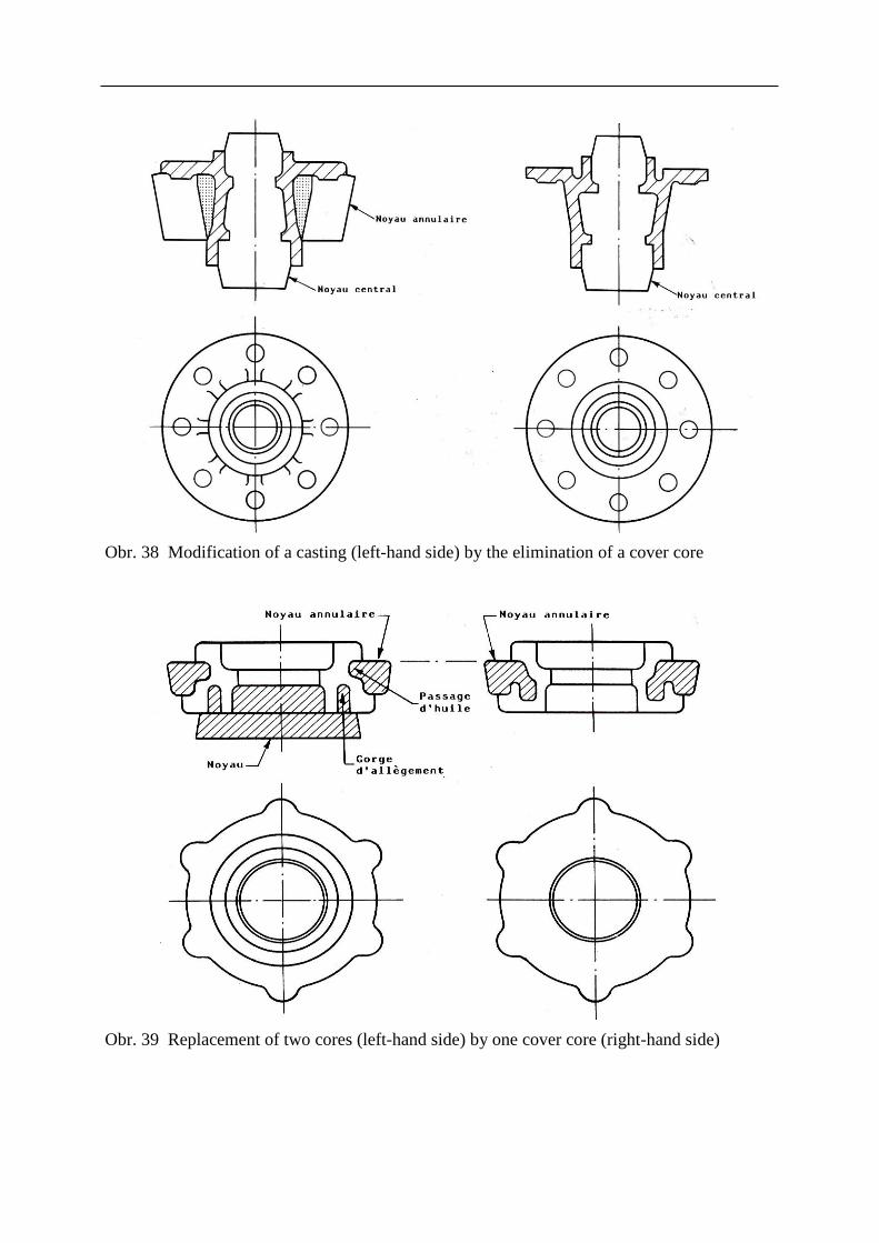
Obr. 38 Modification of a casting (left-hand side) by the elimination of a cover core
Obr. 39 Replacement of two cores (left-hand side) by one cover core (right-hand side)

Obr. 40 Variants of forming a bearing bracket
Core studs
Some cavities do not allow providing a sufficient quantity of core prints, so cores are fixed
using metal studs and spacing elements. A calculation of a size and quantity of studs is
based on a calculation of the weight of cores and metallostatic pressure acting on them.
Obr. 41 Examples of used core studs

Summary of terms of this chapter (subchapters)
1. Methods of core making and processing
2. Core and cover core
3. Methods of seating of cores
Questions to the topic
1. When to use a “true” core and cover core?
2. How is a core seated in a mould?
3. How is gas exhaust from cores solved?
4. Describe core making technologies.
Recommended literature for further study
4 PRINCIPLES OF CASTING DESIGN IN TERMS OF
DIRECTIONAL SOLIDIFICATION
Subchapters:
Basic terms
Objectives
Time needed for the study: individual
Objective: After studying this chapter a student will be able to:
Define particular types of inner and open shrinkages (shrinkage cavities and shrinkage
depressions)
Define a casting module, i.e. time of solidification of a riser and a casting
Define a thermal node and a thermal axis of a casting
Define a function of a riser
Define the directional solidification
Define causes of shrinkage occurrence in castings
Lecture
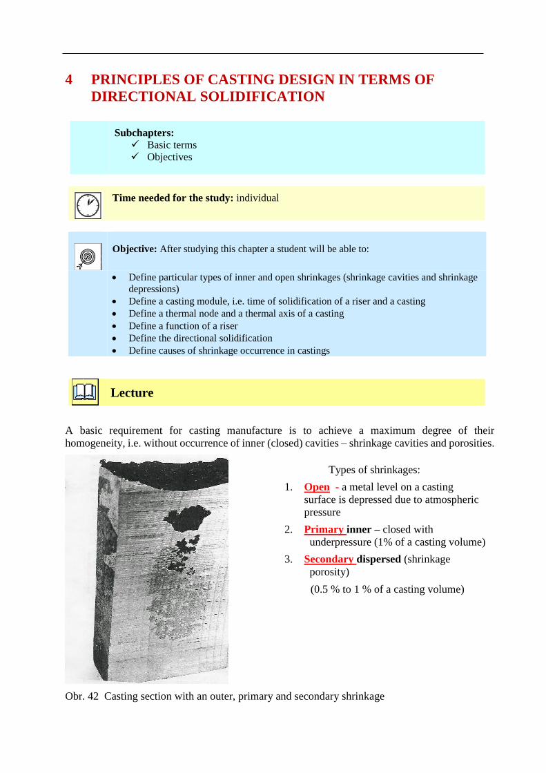
A basic requirement for casting manufacture is to achieve a maximum degree of their
homogeneity, i.e. without occurrence of inner (closed) cavities – shrinkage cavities and porosities.
Obr. 42 Casting section with an outer, primary and secondary shrinkage
Types of shrinkages:
1. Open - a metal level on a casting
surface is depressed due to atmospheric
pressure
2. Primary inner – closed with
underpressure (1% of a casting volume)
3. Secondary dispersed (shrinkage
porosity)
(0.5 % to 1 % of a casting volume)
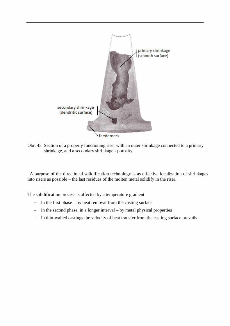
Obr. 43 Section of a properly functioning riser with an outer shrinkage connected to a primary
shrinkage, and a secondary shrinkage - porosity
A purpose of the directional solidification technology is as effective localization of shrinkages
into risers as possible – the last residues of the molten metal solidify in the riser.
The solidification process is affected by a temperature gradient
In the first phase – by heat removal from the casting surface
In the second phase, in a longer interval – by metal physical properties
In thin-walled castings the velocity of heat transfer from the casting surface prevails
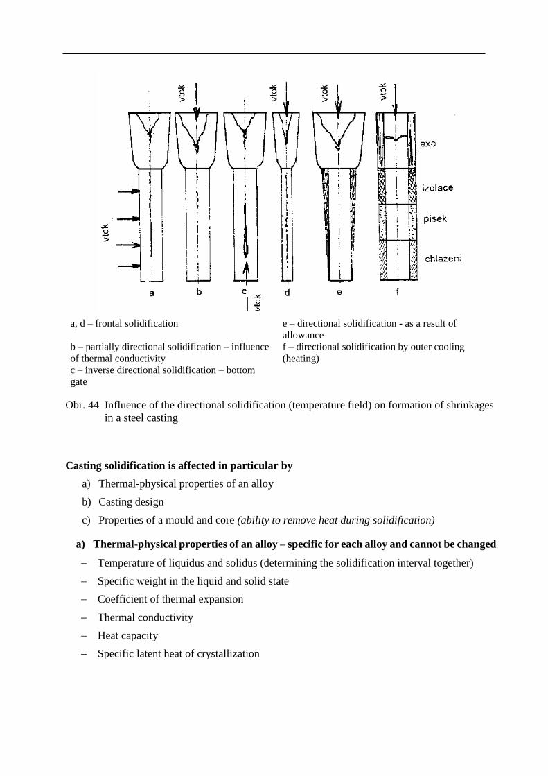
a, d – frontal solidification e – directional solidification - as a result of
allowance
b – partially directional solidification – influence
of thermal conductivity
f – directional solidification by outer cooling
(heating)
c – inverse directional solidification – bottom
gate
Obr. 44 Influence of the directional solidification (temperature field) on formation of shrinkages
in a steel casting
Casting solidification is affected in particular by
a) Thermal-physical properties of an alloy
b) Casting design
c) Properties of a mould and core (ability to remove heat during solidification)
a) Thermal-physical properties of an alloy – specific for each alloy and cannot be changed
Temperature of liquidus and solidus (determining the solidification interval together)
Specific weight in the liquid and solid state
Coefficient of thermal expansion
Thermal conductivity
Heat capacity
Specific latent heat of crystallization

b) Casting design
Objects with the same relative thickness have the same time of solidification under otherwise
identical conditions, the Chvorinov’s rule for predicting the solidification time of steel castings:
cast. = ( M /k )2
cast. – casting solidification time (s)
M – casting module V/S (m)
k – solidification coefficient (m.h- 0.5)
c) Properties of a mould and core – their ability to remove heat during the casting
solidification
The heat absorbing capacity of a mould bf – a complex technological criterion involving
material (sand) of a mould, ramming, moisture etc.
bf = ( . c . ρ)– 0.5 ( W. S0.5. K -1)
– thermal conductivity of a mould, core
c – specific heat capacity of a mould material
ρ – specific weight of a mould material
Obr. 45 Solidification times (s) of moulding sand mixtures with different heat absorbing
capacity coefficients
Open shrinkages – outer open depressions with crystalline and oxidized surface reach into varied
depths, the most frequently occur under improperly dimensioned risers. Shrinkage becomes a
defect, when reaching into a casting, not being located only in a riser.
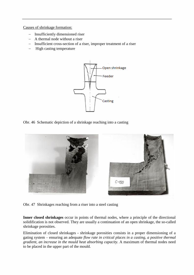
Causes of shrinkage formation:
Insufficiently dimensioned riser
A thermal node without a riser
Insufficient cross-section of a riser, improper treatment of a riser
High casting temperature
Obr. 46 Schematic depiction of a shrinkage reaching into a casting
Obr. 47 Shrinkages reaching from a riser into a steel casting
Inner closed shrinkages occur in points of thermal nodes, where a principle of the directional
solidification is not observed. They are usually a continuation of an open shrinkage, the so-called
shrinkage porosities.
Elimination of closed shrinkages - shrinkage porosities consists in a proper dimensioning of a
gating system – ensuring an adequate flow rate in critical places in a casting, a positive thermal
gradient, an increase in the mould heat absorbing capacity. A maximum of thermal nodes need
to be placed in the upper part of the mould.
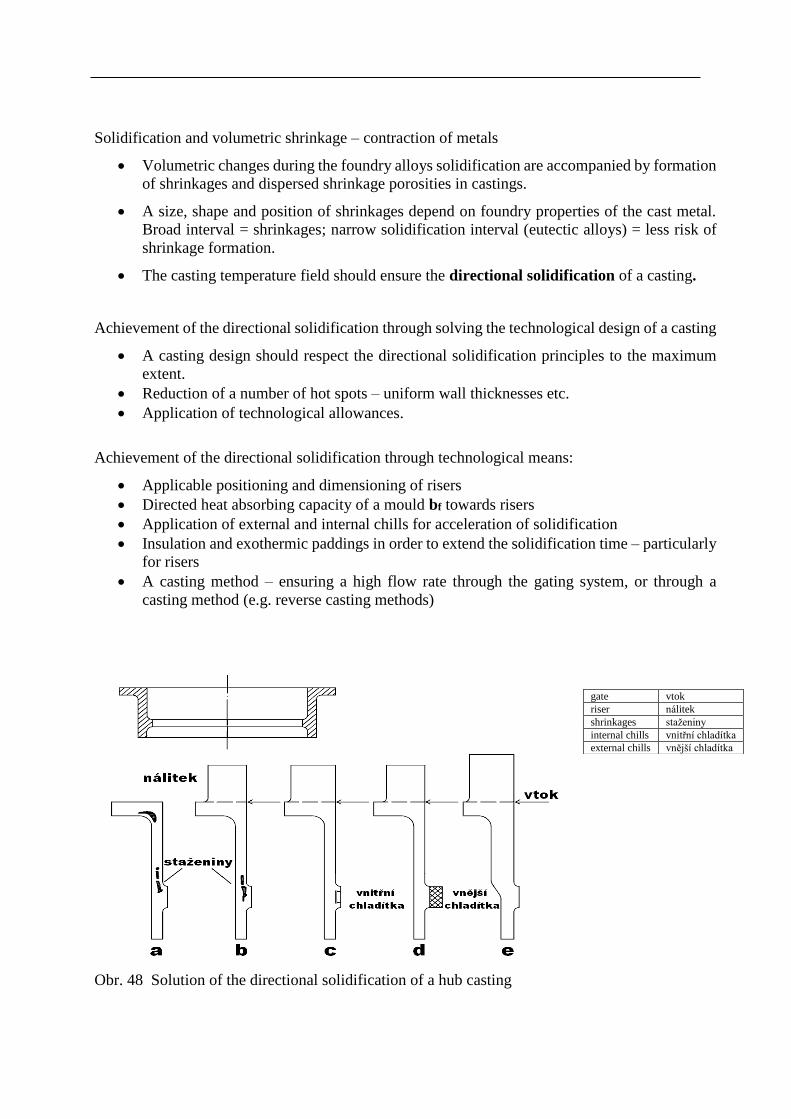
Solidification and volumetric shrinkage – contraction of metals
Volumetric changes during the foundry alloys solidification are accompanied by formation
of shrinkages and dispersed shrinkage porosities in castings.
A size, shape and position of shrinkages depend on foundry properties of the cast metal.
Broad interval = shrinkages; narrow solidification interval (eutectic alloys) = less risk of
shrinkage formation.
The casting temperature field should ensure the directional solidification of a casting.
Achievement of the directional solidification through solving the technological design of a casting
A casting design should respect the directional solidification principles to the maximum
extent.
Reduction of a number of hot spots – uniform wall thicknesses etc.
Application of technological allowances.
Achievement of the directional solidification through technological means:
Applicable positioning and dimensioning of risers
Directed heat absorbing capacity of a mould bf towards risers
Application of external and internal chills for acceleration of solidification
Insulation and exothermic paddings in order to extend the solidification time – particularly
for risers
A casting method – ensuring a high flow rate through the gating system, or through a
casting method (e.g. reverse casting methods)
Obr. 48 Solution of the directional solidification of a hub casting
gate vtok
riser nálitek
shrinkages staženiny
internal chills vnitřní chladítka
external chills vnější chladítka
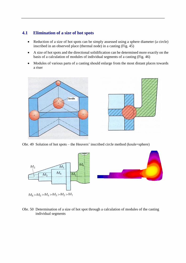
4.1 Elimination of a size of hot spots
Reduction of a size of hot spots can be simply assessed using a sphere diameter (a circle)
inscribed in an observed place (thermal node) in a casting (Fig. 45)
A size of hot spots and the directional solidification can be determined more exactly on the
basis of a calculation of modules of individual segments of a casting (Fig. 46)
Modules of various parts of a casting should enlarge from the most distant places towards
a riser
Obr. 49 Solution of hot spots – the Heuvers’ inscribed circle method (koule=sphere)
Obr. 50 Determination of a size of hot spot through a calculation of modules of the casting
individual segments
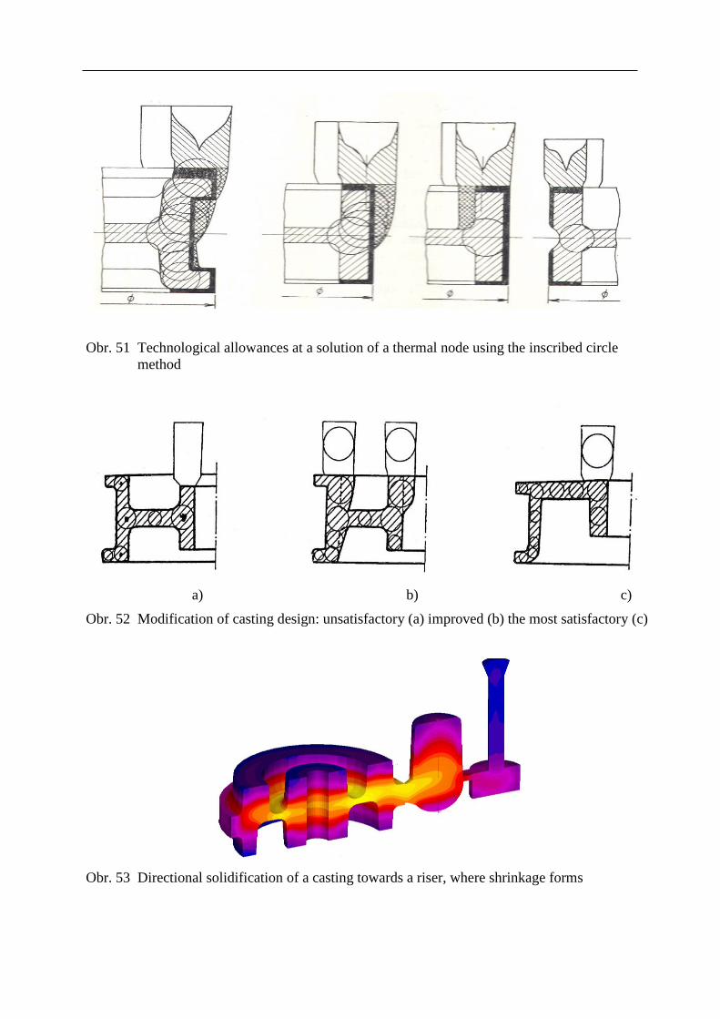
Obr. 51 Technological allowances at a solution of a thermal node using the inscribed circle
method
a) b) c)
Obr. 52 Modification of casting design: unsatisfactory (a) improved (b) the most satisfactory (c)
Obr. 53 Directional solidification of a casting towards a riser, where shrinkage forms

Modification of a casting shape for removal of risers
A design should offer suitable and easily accessible places for attaching a riser. Risers are
difficult to place and remove on oblique and curved surfaces.
Runners of the gating system should be placed into a riser or as close to a riser as possible.
In a case of face risers on the top of a mould, this requirement may collide with a
requirement for quiet bottom filling of a mould.
Reverse casting methods
The methods enable to create an advantageous longitudinal temperature field in a casting during
the casting process. Immediately upon casting, a mould is tilted to such a position, so that the
stream face gets to as low position as possible. This way, intensely through-flow places (including
risers) are as high as possible – a casting is left to solidify in this position.
Only adjacent risers are applied in this method (i.e. to join the gating system). The methods are
applied for castings with a uniform wall thickness and for castings with thermal nodes. The main
advantage of the method is a high technological utilization of metal and very high quality of
castings.
Obr. 54 Partial (acute-angle) reversal at casting into a tilted mould
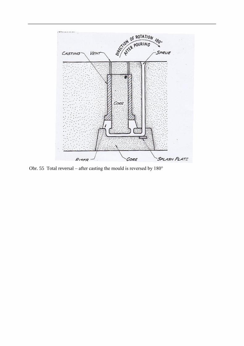
Obr. 55 Total reversal – after casting the mould is reversed by 180°
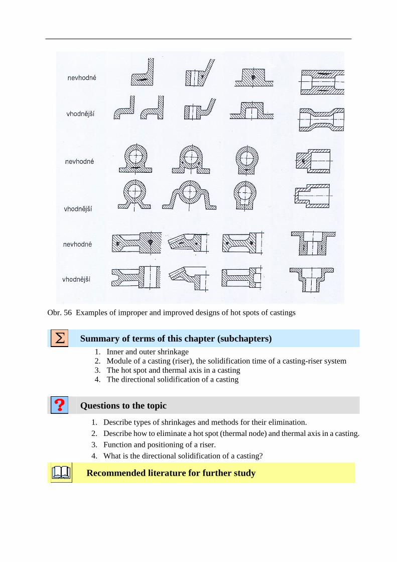
Obr. 56 Examples of improper and improved designs of hot spots of castings
Summary of terms of this chapter (subchapters)
1. Inner and outer shrinkage
2. Module of a casting (riser), the solidification time of a casting-riser system
3. The hot spot and thermal axis in a casting
4. The directional solidification of a casting
Questions to the topic
1. Describe types of shrinkages and methods for their elimination.
2. Describe how to eliminate a hot spot (thermal node) and thermal axis in a casting.
3. Function and positioning of a riser.
4. What is the directional solidification of a casting?
Recommended literature for further study

5 PRINCIPLES OF CASTING DESIGN WITH REGARD TO
STRESS IN CASTINGS
Subchapters:
Basic terms
Objectives
Time needed for the study: individual
Objective: After studying this chapter a student will be able to:
Define volumetric changes during solidification of foundry alloys
Define types of stresses and causes of their origination
Optimize a level of internal stresses through modifications of a casting design
Lecture
Shrinkage during a casting cooling
Volumetric changes in a casting cooling after solidification, a cause of which is thermal expansivity
and possible phase changes in the alloy, result in:
A change in dimensions
Origination of stresses in a casting
A change in a shape (deformation, warping)
Discontinuities (hot tears and cold cracks)
Types of stresses in a casting
• The particular parts of a casting neither cool, nor shrink simultaneously. Non-simultaneous cooling
and shrinking result in differences in dimensions between parts of a casting, causing either stress,
or deformation (warping).
• Shrinkage stress results from a resistance of a mould and cores at high temperatures. It depends
above all on a casting shape and also on strength and collapsibility of moulds and cores. The
resulting (delayed) shrinkage of a casting is usually less than the calculated according to
coefficients of the cast metal thermal expansion.
• Thermal stress originates in the area of elastic-plastic deformations. Parts solidifying faster
impose resistance to parts solidifying more slowly.
• Phase transformation stress results from a non-simultaneous formation of various structure
phases in different areas of a casting during a eutectoid transformation.

Thermal stress
The inner thermal stress, which increases during cooling of a casting down to normal
temperatures, originates as a result of cooling of a casting with different wall thicknesses
at the existence of the temperature gradient.
If it exceeds tensile strength, discontinuities in the material occur (high temperature rears
and cold cracks).
)(. 21 TTE
Internal stress (tension)
Internal stress leads to deformations – it is released especially at machining
Reduces a possibility to load a casting (internal stress adds to the external tension)
It is a cause of a premature casting failure due to occurrence of cold cracks

Obr. 57 Time behavior of length changes of cross-sections 1,2 ∆ l1 and ∆ l2 and their differences
(∆ l1 -∆ l2) during solidification of T - section
Obr. 58 Distortion (deformation) of various sections + tension / - compression [2]
Tab. 3. Characteristics of hottears and cold cracks
Hot tears Cold crack
Temperature at origination Above equicohesion temperature
(high temperature above solidus)
Below temperature tkr, in the area
of predominantly elastic
deformations
Time of origination By a gradual development in three
stages
Immediately (at once)
Causes of origination Mostly tension of exogenous
character
Thermal residual stresses and
transformation stresses
Influence of a casting design Low Decisive
Acoustic effect at the origination Often very loud
Shape Faceted, along grain boundaries Straight – across grains
Surface Oxidized Clean (of a specific colour)

Obr. 59 Geometry of a casting of a gear wheel – gear rim with 6 arms
Obr. 60 Beginning of the solidification – zero level of tensile stresses (brown) and an increased
compression stress (green area)

Obr. 61 End of the solidification – an increased level of tensile (light brown) as well as
compression stresses (green)
Obr. 62 Reduced tension in a gear wheel through reduction of originally 6 arms (bottom) to 5
(top)
Five-arm construction of a wheel and the adapted technology
pětiramenná konstrukce kola a upravená technologie
The original design of the construction and
technology
původní návrh konstrukce a technologie

Obr. 63 Reduced tension when connecting walls with different thicknesses – a wrong and good
solution
Application of reinforcing ribs is advisable for strengthening places where crack occurrence can
be expected. Ribs should have thinner thicknesses than connected walls, so that they solidify faster
and do not extend the time of solidification in the joint. Exceptionally even ribs with reduced
weight are used, however, their manufacture is much more costly.
Obr. 64 Examples of application of reinforcing ribs
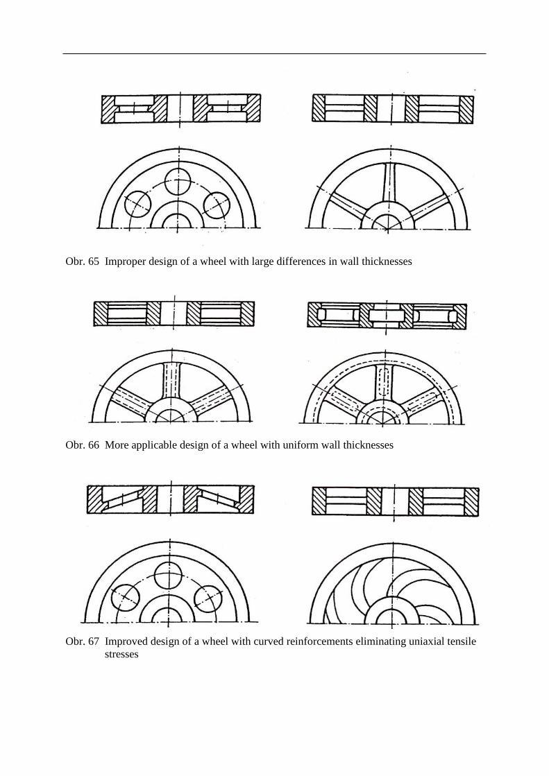
Obr. 65 Improper design of a wheel with large differences in wall thicknesses
Obr. 66 More applicable design of a wheel with uniform wall thicknesses
Obr. 67 Improved design of a wheel with curved reinforcements eliminating uniaxial tensile
stresses
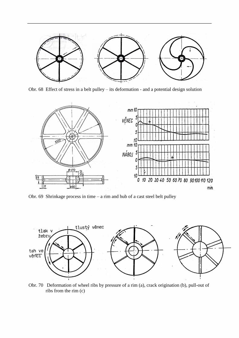
Obr. 68 Effect of stress in a belt pulley – its deformation - and a potential design solution
Obr. 69 Shrinkage process in time – a rim and hub of a cast steel belt pulley
Obr. 70 Deformation of wheel ribs by pressure of a rim (a), crack origination (b), pull-out of
ribs from the rim (c)
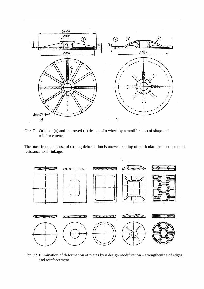
Obr. 71 Original (a) and improved (b) design of a wheel by a modification of shapes of
reinforcements
The most frequent cause of casting deformation is uneven cooling of particular parts and a mould
resistance to shrinkage.
Obr. 72 Elimination of deformation of plates by a design modification – strengthening of edges
and reinforcement
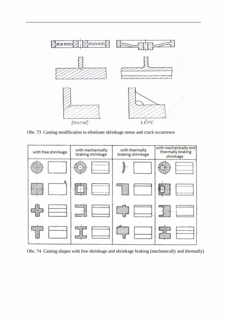
Obr. 73 Casting modification to eliminate shrinkage stress and crack occurrence
Obr. 74 Casting shapes with free shrinkage and shrinkage braking (mechanically and thermally)
Summary of terms of this chapter (subchapters)
1. Shrinkage, phase and thermal stress in castings
2. Mechanism of origination of hot tears and cold cracks
3. Construction modifications for stress elimination in castings
Questions to the topic
1. Define particular shrinkage, thermal and phase stresses in a casting.
2. Describe methods for elimination of stress in a casting.
3. Characterize causes of origination of hottears and cold cracks.
4. Describe design modifications for elimination of stress in castings.
Recommended literature for further study

6 PRINCIPLES OF A CASTING DESIGN IN TERMS OF
FETTLING AND FINISHING
Subchapters:
Basic terms
Objectives
Time needed for the study: individual
Objective: After studying this chapter a student will be able to:
Define casting design modifications to facilitate fettling
Apply principles for cost reduction of finishing procedures
Lecture
Casting fettling costs often cover 15 to 25 % of the rough casting total cost
These costs also include removal of risers and grinding
These costs can be reduced by 30 to 50 % through a design modification
These changes are often simple and non-costly
A casting design has to meet the following demands:
Avoid places where sticking of a sand mixture occurs easily
Ensure an access of a blasting mean into all cavities of a casting. Castings should not have
inaccessible cavities
If possible, a parting plane of a mould should be flat to facilitate removal of flash. If not
possible, these areas should be fitted with additional ribs onto which the flash “displaces”
Avoid thin protrusions and ribs on tiny castings from brittle materials
Ensure easy removal of risers and gating
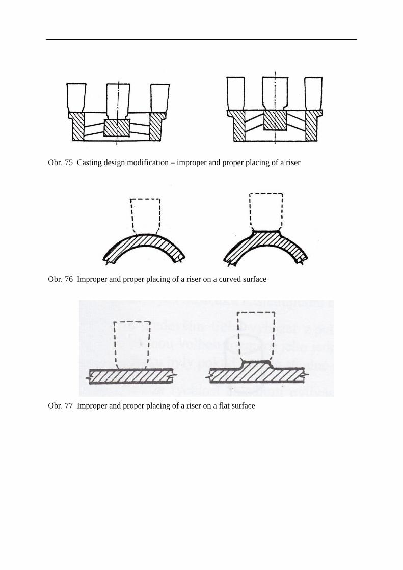
Obr. 75 Casting design modification – improper and proper placing of a riser
Obr. 76 Improper and proper placing of a riser on a curved surface
Obr. 77 Improper and proper placing of a riser on a flat surface
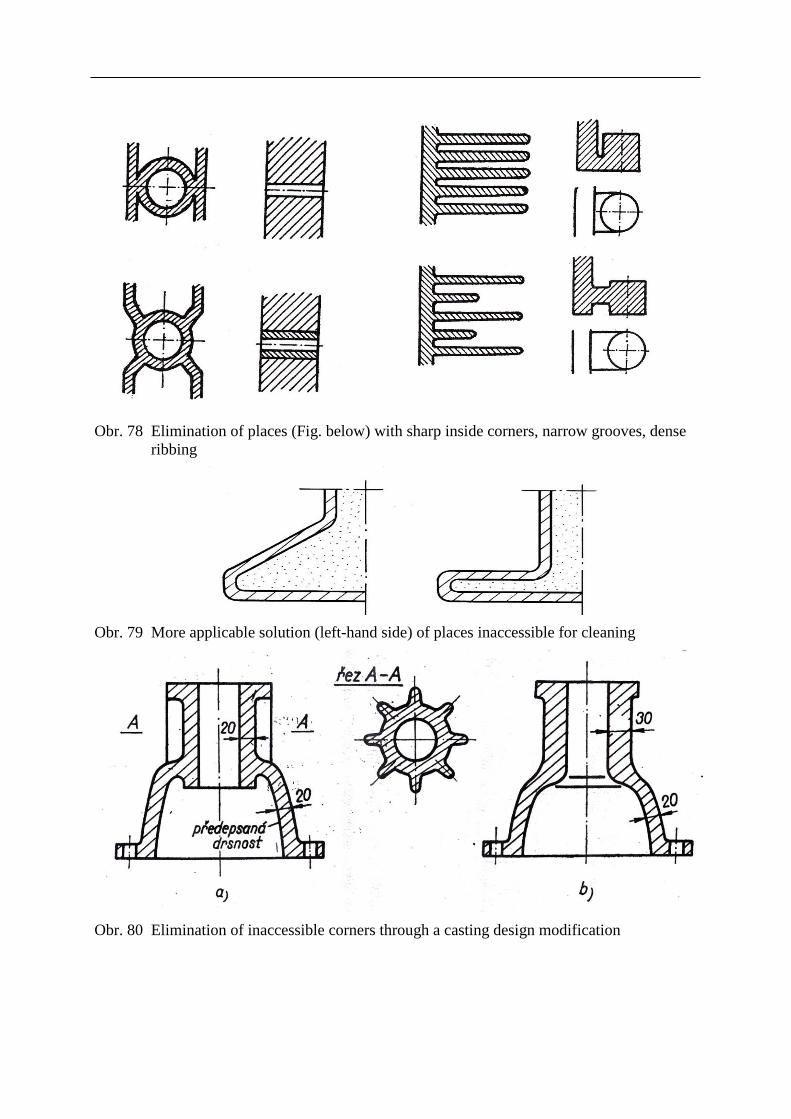
Obr. 78 Elimination of places (Fig. below) with sharp inside corners, narrow grooves, dense
ribbing
Obr. 79 More applicable solution (left-hand side) of places inaccessible for cleaning
Obr. 80 Elimination of inaccessible corners through a casting design modification
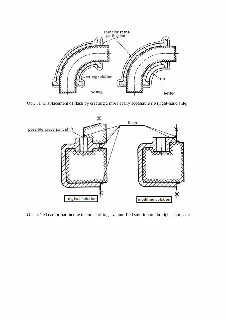
Obr. 81 Displacement of flash by creating a more easily accessible rib (right-hand side)
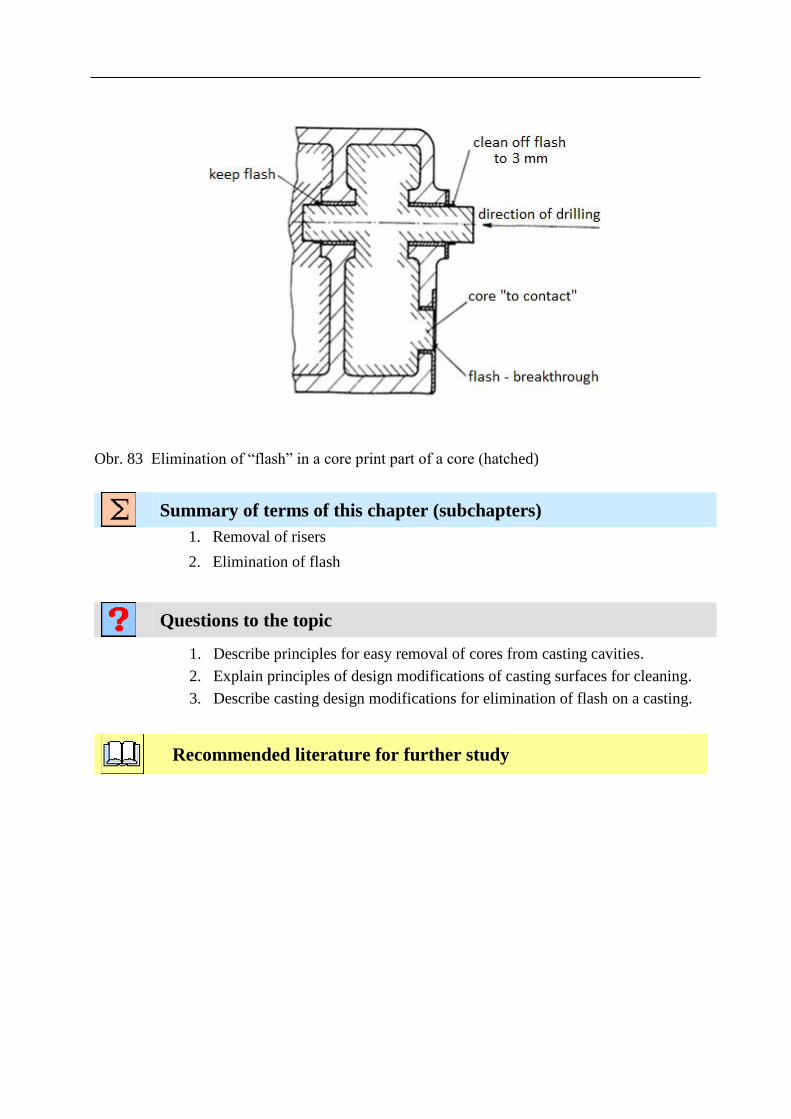
Obr. 82 Flash formation due to core shifting – a modified solution on the right-hand side
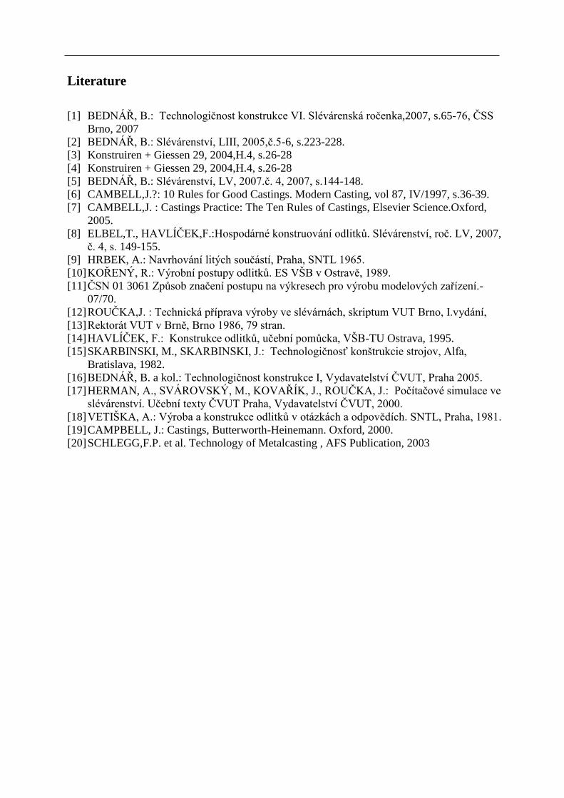
Obr. 83 Elimination of “flash” in a core print part of a core (hatched)
Summary of terms of this chapter (subchapters)
1. Removal of risers
2. Elimination of flash
Questions to the topic
1. Describe principles for easy removal of cores from casting cavities.
2. Explain principles of design modifications of casting surfaces for cleaning.
3. Describe casting design modifications for elimination of flash on a casting.
Recommended literature for further study
Literature
[1] BEDNÁŘ, B.: Technologičnost konstrukce VI. Slévárenská ročenka,2007, s.65-76, ČSS
Brno, 2007
[2] BEDNÁŘ, B.: Slévárenství, LIII, 2005,č.5-6, s.223-228.
[3] Konstruiren + Giessen 29, 2004,H.4, s.26-28
[4] Konstruiren + Giessen 29, 2004,H.4, s.26-28
[5] BEDNÁŘ, B.: Slévárenství, LV, 2007.č. 4, 2007, s.144-148.
[6] CAMBELL,J.?: 10 Rules for Good Castings. Modern Casting, vol 87, IV/1997, s.36-39.
[7] CAMBELL,J. : Castings Practice: The Ten Rules of Castings, Elsevier Science.Oxford,
2005.
[8] ELBEL,T., HAVLÍČEK,F.:Hospodárné konstruování odlitků. Slévárenství, roč. LV, 2007,
č. 4, s. 149-155.
[9] HRBEK, A.: Navrhování litých součástí, Praha, SNTL 1965.
[10] KOŘENÝ, R.: Výrobní postupy odlitků. ES VŠB v Ostravě, 1989.
[11] ČSN 01 3061 Způsob značení postupu na výkresech pro výrobu modelových zařízení.-
07/70.
[12] ROUČKA,J. : Technická příprava výroby ve slévárnách, skriptum VUT Brno, I.vydání,
[13] Rektorát VUT v Brně, Brno 1986, 79 stran.
[14] HAVLÍČEK, F.: Konstrukce odlitků, učební pomůcka, VŠB-TU Ostrava, 1995.
[15] SKARBINSKI, M., SKARBINSKI, J.: Technologičnosť konštrukcie strojov, Alfa,
Bratislava, 1982.
[16] BEDNÁŘ, B. a kol.: Technologičnost konstrukce I, Vydavatelství ČVUT, Praha 2005.
[17] HERMAN, A., SVÁROVSKÝ, M., KOVAŘÍK, J., ROUČKA, J.: Počítačové simulace ve
slévárenství. Učební texty ČVUT Praha, Vydavatelství ČVUT, 2000.
[18] VETIŠKA, A.: Výroba a konstrukce odlitků v otázkách a odpovědích. SNTL, Praha, 1981.
[19] CAMPBELL, J.: Castings, Butterworth-Heinemann. Oxford, 2000.
[20] SCHLEGG,F.P. et al. Technology of Metalcasting , AFS Publication, 2003