
vpn_failover_configuration_example_(en-US).pdf
16
Use a Branch Office VPN for Failover From a Private Network Link Example configuration files created with — WSM v11.7.2 Revised — 3/29/2013 Use Case In this conf iguration example, an organization has n etworks at two sites and uses a private network link to send traf fic between the two net works. To make their network configurat ion more fault- tolerant, they want to set up a secondary route between the network s to use as a backup if the priv ate network link fails,but they do not want to spend money on a second private network connect ion. To solve this problem, they can use a branch office VPN with dynamic rout ing. This conf iguration example provides a model of how you could set up your network to aut omatically f ail over to a branch off ice VPN if a primary private network connect ion between two sites becomes unavailable. To use the branch offic e VPN connection f or automat ic f ailover, you must enable dynamic routing on t he XTM device at each sit e. You can use any supported dynamic rout ing protocol (RIP v 1, RIP v2, OSPF, or BGP v 4). This c onfiguration example is provided as a guide. Additional configurat ion sett ings could be necessary, or more appropriate, for your net work environment. Solution Overview A rou ting protocol is the method routers u se to communicate with each other and share information abou t the status o f network rout ing tables. On t he XTM device, st atic r outes are persis tent and do not change, even if the link t o the next hop goes down. When you enable dynamic routing, the XTM device automat ically updates the rout ing table based on the status of the connection. When you c onfigure dynamic routing for traf fic sent through the private network connection, if the privat e network connect ion fails, the XTM device automatic ally removes that route from t he routing table. After you configure dynamic routing betwee n the two sites, you then configure a b ranch office VPN tunnel betwee n the two sites on another XT M device interf ace. As part of the VP N configurat ion, you enable the global VPN s ett ing Enable the use of non-defaul t (static or dynamic) r outes to determine if IPSec is used. Configuration Example
Transcript of vpn_failover_configuration_example_(en-US).pdf

8/10/2019 vpn_failover_configuration_example_(en-US).pdf
http://slidepdf.com/reader/full/vpnfailoverconfigurationexampleen-uspdf 1/16
Use a Branch Office VPN for Failover From a
Private Network Link
Example configuration files created with — WSM v11.7.2
Revised — 3/29/2013
Use Case
In this configuration example, an organization has n etworks at two sites and uses a private network link to send traffic
between the two networks. To make their network configuration more fault-tolerant, they want to set up a secondary route
between the networks to use as a backup if the private network link fails, but they do not want to spend money on a second
private network connection. To solve this problem, they can use a branch office VPN with dynamic routing.
This configuration example provides a model of how you could set up your network to automatically fail over to a branch
office VPN if a primary private network connection between two sites becomes unavailable. To use the branch office VPN
connection for automatic failover, you must enable dynamic routing on the XTM device at each site. You can use any
supported dynamic routing protocol (RIP v1, RIP v2, OSPF, or BGP v4).
This configuration example is provided as a guide. Additional configuration settings could be necessary, or
more appropriate, for your network environment.
Solution Overview
A rou ting protocol is the method routers u se to communicate with each other and share information abou t the status of
network routing tables. On the XTM device, static routes are persistent and do not change, even if the link to the next hop
goes down. When you enable dynamic routing, the XTM device automatically updates the routing table based on the status
of the connection. When you configure dynamic routing for traffic sent through the private network connection, if the private
network connection fails, the XTM device automatically removes that route from the routing table.
After you configure dynamic routing between the two sites, you then configure a b ranch office VPN tunnel between the two
sites on another XTM device interface. As part of the VPN configuration, you enable the global VPN setting Enable the use
of non-default (static or dynamic) routes to determine if IPSec is used.
Configuration
Example

8/10/2019 vpn_failover_configuration_example_(en-US).pdf
http://slidepdf.com/reader/full/vpnfailoverconfigurationexampleen-uspdf 2/16
How It Works
When the global VPN setting is enabled, the XTM device uses the status of the routing table to decide whether to send traffic
through the branch office VPN tunnel.
With this configuration:
n When the private network connection is established between the two sites, the XTM device at each site adds the
dynamic route to the routing table. Because the route is present in the routing table, each XTM device sends traffic to
the other site over the private connection.
n If the private network connection fails, the XTM device at each site removes that route from the routing table. Because
the route is not present in the routing table, each XTM device sends traffic to the other site through the encrypted IPSec
branch office VPN tunnel.
n When the private network connection is restored, the dynamic route is added to the routing table at each site, and the
two devices automatically begin to send traffic over the private network connection again.
Requirements
For VPN failover to operate correctly, the configuration must meet these requirements:
n The XTM device at each site must use Fireware XTM v11.3.1 or later.
n The two sites must have a primary connection over a private network link, such as a leased line or MPLS network.
n The primary network connection between the two sites must terminate at the XTM device at each site.
n The trusted and optional networks at each site must use the XTM device as the default gateway.
n Dynamic routing (OSPF, BGP, or RIP) must be enabled on the XTM devices for the primary private network link
between sites. Fireware XTM with a Pro upg rade is required to use OSPF or BGP v4.
n A branch office VPN must be configured between the XTM devices at each site.
n The Enable the use of non-default (static or dynamic) routes to determine if IPSec is used global VPN setting must
be enabled on the XTM devices at both sites.
Use a Branch Office VPN for Failover From a Private Network Link
2 WatchGuard Fireware XTM

8/10/2019 vpn_failover_configuration_example_(en-US).pdf
http://slidepdf.com/reader/full/vpnfailoverconfigurationexampleen-uspdf 3/16
Use a Branch Office VPN for Failover From a Private Ne twork Link
Configuration Example 3
Network Topology
To configure automatic network failover, the private network link between the two sites must terminate at the XTM devices at
each site. At a high level, this generic network diagram shows the relationship between the networks at the two sites.
In this diagram, the Private Network Cloud could represent any one of several possible methods to connect the two sites over
a private network. All of these connection types are supported for dynamic failover to a VPN connection.
Point-to-Point Link
In this type of connection, the XTM devices at the two sites connect directly to each other. Typical examples of this type of
connection are fiber optic connection, fiber-to-Ethernet converters, layer 2 VLAN connections, or a leased line with serial-
to-Ethernet converters at each end.
Multi-Hop Link
In this type of connection, the XTM device at each site is connected to a router and the routers are connected by point-to-
point links. The routers could be managed by the network administrators at each site, or by the service provider. A typical
example of this type of connection is a leased line terminated on routers at each site.
MPLS Link
In this type of connection, the XTM device at each site connects to a router on an MPLS network. In this case, the routersare usually owned and manage d by the service provider. A typical example of this type of connection is an MPLS or L2TP
private network connection.
These connection types are explained more fully in the next section.

8/10/2019 vpn_failover_configuration_example_(en-US).pdf
http://slidepdf.com/reader/full/vpnfailoverconfigurationexampleen-uspdf 4/16
Example Network Topologies
For automatic failover to a VPN to operate correctly, the private network link between the two sites must terminate on a trusted
or optional ne twork interface on the XTM device at each site. This interface must be separate from the trusted network.
In this configuration example, we present two specific network topologies to illustrate the supported network connection types:
private network connection o ver point-to-poi nt link and private network connection over multi-hop link or MPLS. The example
configuration files that accompany this document show configuration settings for each private network connection type. For
similar topologies that are not supported, see the section Appendix — Unsupported Network Topologies.
Private Network Connection Over Point-to-Point Link
In a point-to-point link, the private network connection between the two sites is a leased line, with a serial-to-Ethernet converter
at each end. This point-to-point link connects directly to an interface on each XTM device.
In this network diagram, the XTM devices at the two sites use these IP addresses:
Site A Site B
External interface IP address 192.0.2.20/24 198.51.100.30/24
Default Gateway IP address 192.0.2.1 198.51.100.1
IP address of the XTM device interface connected to the trusted network 10.0.20.1/24 10.0.30.1/24
Trusted network IP address 10.0.20.0/24 10.0.30.0/24
IP address of the XTM device interface connected to the private leased line 192.168.100.1/30 192.168.100.2/30
Example Network Topologies
4 WatchGuard Fireware XTM

8/10/2019 vpn_failover_configuration_example_(en-US).pdf
http://slidepdf.com/reader/full/vpnfailoverconfigurationexampleen-uspdf 5/16
Example Network Topologies
Configuration Example 5
With this type of connection, there are no routers to configure. Only these addresses are required to enable dynamic routing
over the private leased line b etween the two sites. The recommended dynamic routing protocol for this type of private network
topology is OSPF.
Private Network Connection Over Multi-Hop Link or MPLS
If the private network link is a multi-hop link or MPLS network, the XTM device at each site connects to a router configured at
the edge of a leased line or MPLS network. In this topology, you must add a static route on each XTM device to define the IP
address of the local router on the private network as the next hop to the other XTM device.
In this network diagram, the XTM devices at the two sites use these IP addresses:
Site A Site B
External interface IP address 192.0.2.20/24 198.51.100.30/24
Default gateway IP address 192.0.2.1 198.51.100.1
IP address of the XTM device interface connected to the trusted network 10.0.20.1/24 10.0.30.1/24
Trusted network IP address 10.0.20.0/24 10.0.30.0/24
IP address of the XTM device interface connected to the router 192.168.100.1/30 192.168.200.1/30
LAN IP address of the router connected to the private network link 192.168.100.2/30 192.168.200.2/30
WAN IP address of the router connected to the private network link 10.0.3.1/30 10.0.3.2/30
At each end of the leased line or MPLS network between the two XTM devices, are routers that can either be managed by the
network administrator at each site, or managed by the network service provider. In this configuration, you must set up static
routes on each XTM device and on each router to correctly direct the traffic between the two networks.

8/10/2019 vpn_failover_configuration_example_(en-US).pdf
http://slidepdf.com/reader/full/vpnfailoverconfigurationexampleen-uspdf 6/16
For the XTM device at Site A to be able to reach the interface of the XTM device at Site B (192.168.200.1/30), you must add
static routes to the XTM device and to the router at Site A. For the XTM device at Site B to be a ble to reach the interface of the
XTM device at site A (192.168.100.1/30), you must add static routes to the XTM device and to the router at Site B. You must
also configure static routes on the routers at each site to allow the traffic between the trusted networks at each site.
If you configure dynamic routing between each XTM device and the local MPLS router, you do not have toadd static routes to the MPLS routers. For this configuration example, we assume you u se static routing
between the XTM device and the local router.
The static routes for the XTM device and the router at each site are:
Static Routes at Site A
XTM Device at Site A Site A Router
Route to Site B XTM device Network: 192.168.200.0/30
Next Hop: 192.168.100.2
Network: 192.168.200.0/30
Next Hop: 10.0.3.2
Route to Site A trusted network
Network: 10.0.20.0/24
Next Hop: 192.168.100.1
Route to Site B trusted network Network: 10.0.30.0/24
Next Hop: 10.0.3.2
Static Routes at Site B
XTM Device at Site B Site B Router
Route to Site A XTM deviceNetwork: 192.168.100.0/30
Next Hop: 192.168.200.2
Network: 192.168.100.0/30
Next Hop: 10.0.3.1
Route to Site A trusted network
Network: 10.0.20.0/24
Next Hop: 10.0.3.1
Route to Site B trusted network Network: 10.0.30.0/24
Next Hop: 192.168.200.1
After you configure the static routes and verify that the devices can contact each other, you can configure dynamic routing
across the private network link. The recommended dynamic routing protocol for this configuration is BGP.
In this example configuration, dynamic routing occurs only between the XTM devices. The routers connected to the private
network link do not use dynamic routing.
Example Network Topologies
6 WatchGuard Fireware XTM

8/10/2019 vpn_failover_configuration_example_(en-US).pdf
http://slidepdf.com/reader/full/vpnfailoverconfigurationexampleen-uspdf 7/16
Example Configuration Files
Configuration Example 7
Example Configuration Files
For your reference, we have included six example configuration files with this document. To examine the details of the
example configuration files, you can open them with Policy Manager. Make sure to use Policy Manager v11.3.1 or later,
because the VPN failover option is not supported in earlier versions of Policy Manager.
The example configuration files show the configurations for Site A and Site B for each of the three dynamic routing
configuration protocols. Only the BGP configuration files include the static routes required for a multi-hop link or an MPLS
private network connection.
Description Configuration Filename
BGP configuration BGP-Site-A-multi-hop-with-VPN.xml
BGP-Site-B-multi-hop-with-VPN.xml
OSPF configuration OSPF-Site-A-with-VPN.xml
OSPF-Site-B-with-VPN.xml
RIP configuration RIP-Site-A-with-VPN.xml
RIP-Site B-with-VPN.xml
The settings configured in the example configuration files are described in the subsequent sections.

8/10/2019 vpn_failover_configuration_example_(en-US).pdf
http://slidepdf.com/reader/full/vpnfailoverconfigurationexampleen-uspdf 8/16

8/10/2019 vpn_failover_configuration_example_(en-US).pdf
http://slidepdf.com/reader/full/vpnfailoverconfigurationexampleen-uspdf 9/16
Dynamic Routing Configuration
Configuration Example 9
Dynamic Routing Policy
When you enable a dynamic routing protocol, a policy is required to allow the traffic. Policy Manager automatically creates the
required policy.
To see the dynamic routing policy:
1. In Policy Manager, open one of the example configuration files.
2. Double-click the DR -RIP-Allow, DR-OSPF-Allow, or DR-BGP-Allow policy to edit it.
For example, the DR-OSPF-Allow policy in the Site A OSPF example configuration looks like this:
8/10/2019 vpn_failover_configuration_example_(en-US).pdf
http://slidepdf.com/reader/full/vpnfailoverconfigurationexampleen-uspdf 10/16
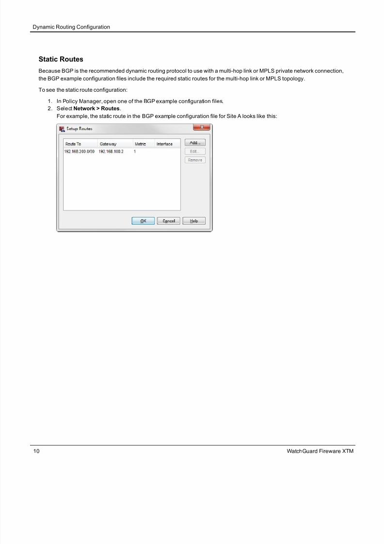
Static Routes
Because BGP is the recommended dynamic routing protocol to use with a multi-hop link or MPLS private network connection,
the BGP example configuration files include the required static routes for the multi-hop link or MPLS topology.
To see the static route configuration:
1. In Policy Manager, open one of the BGP example configuration files.
2. Select Network > Routes.
For example, the static route in the BGP example configuration file for Site A looks like this:
Dynamic Routing Configuration
10 WatchGuard Fireware XTM

8/10/2019 vpn_failover_configuration_example_(en-US).pdf
http://slidepdf.com/reader/full/vpnfailoverconfigurationexampleen-uspdf 11/16
VPN Configuration
Configuration Example 11
VPN Configuration
Each of the example configuration files contains a branch office gateway and a branch office tunnel that are configured to
match any of the network diagrams presented in this use case. The gateway and tunnel settings for each site are the same,
regardless of the dynamic routing protocol, or the type of private network connection between the two sites. You can open any
of the Site A or Site B example configuration files to see these settings.
VPN Settings at Site A
The VPN Gateway settings at Site A are available in any of the example configuration files for Site A.
To see the gateway settings:
1. Select VPN > Branch Office Gateways.
2. Select the gateway name, SiteA-SiteB-GWY. Click Edit.
To see the tunnel settings:
1. Select VPN > Branch Office Tunnels.
2. Select the tunnel name, SiteA-SiteB-Tunnel. Click Edit.
For example, the tunnel in the example configuration file for Site A looks like this:

8/10/2019 vpn_failover_configuration_example_(en-US).pdf
http://slidepdf.com/reader/full/vpnfailoverconfigurationexampleen-uspdf 12/16
To see the VPN failover setting:
1. Select VPN > Settings.
2. The Enable the use of non-default (static or dynamic) routes to determine if IPSec is used check box is selected.
This check box enables the automatic failover to the VPN based on dynamic changes to the routing table.
VPN Settings at Site B
The VPN Gateway settings at Site B are available in any of the example configuration files for Site B. To see the gateway,
tunnel, and VPN failover settings for Site B, repeat the same steps you completed for Site A.
Conclusion
This configuration example demonstrates one method you can use to configure dynamic routing over a private link between
two sites, and how to configure the XTM devices at each site for automatic failover from the private network link to a branch
office VPN. When you use this type of configuration, if the private network link route fails, a packet between the two networks
can automatically use the VPN tunnel to get to its destination.
For more information about dynamic routing and branch office VPNs, see the Fireware XTM WatchGuard System Manager
Help.
Conclusion
12 WatchGuard Fireware XTM

8/10/2019 vpn_failover_configuration_example_(en-US).pdf
http://slidepdf.com/reader/full/vpnfailoverconfigurationexampleen-uspdf 13/16
Appendix — Un supported Network Topolog ies
Configuration Example 13
Appendix — Unsupported Network Topologies
This section illustrates two network topologies that are not supported for this example.
Topology 1
The router that connects to the private network cloud is also the default gateway for the trusted network.
In this topology, the default gateway for the trusted network at each site is the router that connects each site. Because of this,
the XTM device cannot control routing between the two networks. You can, however, configure the routers that connect the two
sites for dynamic routing and to fail over to a route through the VPN tunnel on the XTM device. This network topology method
is out of the scope of this configuration example because to do this you must configure that type of failover on the router.
There is also a possible security concern with this topology: because there is no firewall o n the private network link between
the two sites, any security compromise at one site can affect both sites.

8/10/2019 vpn_failover_configuration_example_(en-US).pdf
http://slidepdf.com/reader/full/vpnfailoverconfigurationexampleen-uspdf 14/16
Topology 2
The router that connects to the private network cloud connects directly to the trusted network, but is not the default gateway for
the trusted network.
In this topology, the XTM device cannot control network failover between the two sites because there is not a single ing ress
and egress point at each site. We always recommend that you configure the XTM device as the single ingress and egress
point on each network.
The larger problem with this topology is that it can create asymmetric routes between the two sites. Connections between the
two sites can fail regardless of whether TCP SYN checking is enabled, because the firewall at each site might see only one
side of the TCP handshake.
Asymmetric routing can occur b ecause:
1. Packets sent from a computer at Site A to a computer at Site B are routed through the default gateway at Site A (the Site
A XTM device). The p ackets are then routed over the peer link to the computer at Site B. These p ackets do not go
through the Site B XTM device.
2. The returned packets from the computer at Site B are routed through the default gateway at Site B (the Site B XTM
device). The packets are then routed over the peer link to the computer at Site A. These packets do not go through the
Site A XTM device.
Even without dynamic routing or failover to a VPN, this network configuration can cause routing problems and is not
recommended.
Appendix — Un supported Network Topologies
14 WatchGuard Fireware XTM
8/10/2019 vpn_failover_configuration_example_(en-US).pdf
http://slidepdf.com/reader/full/vpnfailoverconfigurationexampleen-uspdf 15/16

8/10/2019 vpn_failover_configuration_example_(en-US).pdf
http://slidepdf.com/reader/full/vpnfailoverconfigurationexampleen-uspdf 16/16
About this Co nfiguration Example
Configuration Example 16


![[en-us] bosch-home.com/us/mybosch mybosch [en-us] Dishwasher](https://static.fdocuments.in/doc/165x107/615cc8afbe7e0d1e5a38c77e/en-us-bosch-homecomusmybosch-mybosch-en-us-dishwasher.jpg)
