Volume Control Dampers
13
VOLUME CONTROL DAMPERS WE SHAPE AIR PRODUCTS CATALOGUE PRODUCT BULLETIN
-
Upload
sreejeshkeralam -
Category
Documents
-
view
68 -
download
6
Transcript of Volume Control Dampers

VOLUME CONTROL DAMPERS
WE SHAPE
AIR
PRODUCTS CATALOGUE
PRODUCT BULLETIN

Dubai Head Office:
Tel: +971 4 706 97777Fax: +971 4 706 9787
Abu Dhabi Branch:
Tel: +971 2 645 0107Fax: +971 2 645 0167
Email: [email protected]
P.O. Box 50708, DubaiUnited Arab Emirates
w w w . b e t a g . c o m

index
RECTANGULAR VOLUME CONTROL DAMPERS
STAINLESS STEEL VCD & VDR
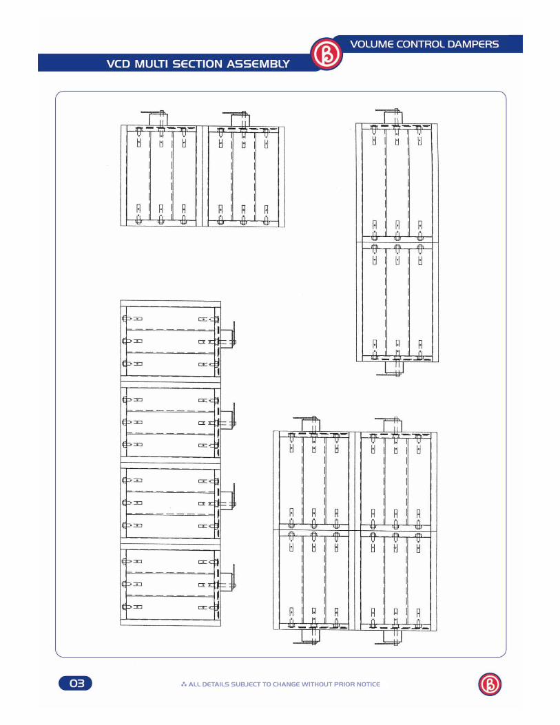
VCD MULTI SECTION ASSEMBLY
MOTORIZED VOLUME CONTROL DAMPER
MECHANICAL FLOW RATE CONTROLLER MRP - 1
MECHANICAL FLOW RATE CONTROLLER MRP - 2
1
2
3
4-6
7-8
9-10

VOLUME CONTROL DAMPERS
Frame
Blades
: 1..2 mm thick Galvanized steel with
: welding / clinching corners
: 0.9 mm (optional)
: Extuded Aluminium profile aero foil blades, 1mm thick
: 75, 100 & 150 mm blade width to suit different sizes
Bushings
Control shaft
Quadrant
: Plastic self oiling type
: 6” long plated steel , 1/2” square bar
: From stamped G1
133210
192.410
10 10
180133
25
H x
W
H x
W
H x
W
H x
WGE
AR
SIZ
E
VCD-Flange type VCD-Slip & Clip type VCD-Box type VCD withgear mechanism
PATTERN OPTIONS SIZE W x H: WIDTH x HEIGHTMIN SIZE : 100 x 100 MM
MAX SIZE : 1000 x 1000 MM
SIZES ABOVE THIS SIZE WILL BE MADE IN MULTIPLE SECTION AS PER SKETCH PAGE NO.3
FIXINGF=FLANGEDSC=SLP & CLIPB=BOX
BLADE MOVEMENT O=OPPOSED (STD)A=PARALLEL
MECHANISML=LINK (STD)G=GEAR
VCD: VOLUME CONTROLDAMPERO
rder
ing
Sy
stem
INTRODUCTION
RECTANGULAR VOLUME CONTROL DAMPERS
VOLUME CONTROL DAMPERS
ALL DETAILS SUBJECT TO CHANGE WITHOUT PRIOR NOTICE

VOLUME CONTROL DAMPERS
STAINLESS STEEL VCD
STAINLESS STEEL VCD
Frame
Blade
Bearing Shaft Handle
: S. Steel sheet 1.2mm thickness
: S. Steel sheet 0.9mm thickness
: Round Brass/S. Steel : S. Steel Round section : S.Steel
Stainless SteelBrass Bush
Handle SS plate
Ord
erin
g S
yste
m PATTERN OPTIONS SIZE W x H: WIDTH x HEIGHTMIN SIZE : 100 x 100 MM
MAX SIZE : 1000 x 1000 MM
SIZES ABOVE THIS SIZE WILL BE MADE IN MULTIPLE SECTION AS PER SKETCH PAGE NO.3
FIXINGF=FLANGEDSC=SLP & CLIPB=BOX
BLADE MOVEMENT O=OPPOSED (STD)A=PARALLEL
MECHANISML=LINK (STD)G=GEAR
SSVCD: STAINLESS STEELVOLUME CONTROL DAMPER
ROUND VOLUME CONTROL DAMPER - VDR
The frame and blade in Round Volume Control Damper are made of 0.9 mm galvanized
steel and unit is fixed with hand quadrant for manual operation.
The finishing is mill galvanized.
Axle: 1/2” square aluminium hollow tube riveted to blade
L= DIA + 60 mm
TYPE SIZE
: DIAMETER
VDR: ROUND VOLUME CONTROL
DAMPER
Diameter
30 m
m30 m
m
ALL DETAILS SUBJECT TO CHANGE WITHOUT PRIOR NOTICE
Blade 0.9m thick SS sheet
Shaft SS Round section
Frame 1.2mm thick SS sheet
ALL DETAILS SUBJECT TO CHANGE WITHOUT PRIOR NOTICE

MOTORIZED VOLUME CONTROL DAMPER
Frame : G1 1.2 mm with welded corner
Blades: Aluminium aerofoil type - 1mm thick
Mechanism of movement: plastic gear of 100mm Dia.
The control shaft: 10” long plated steel 1/2 inch square bar.
Motorized VCD can be supplied without motor with provision to fix motor.
MOTORS: As a standard: Belimo models used with our product.
Other models can be used on request.
TYPE OF MOTORS: 1) Open / Close type without spring return function.
2) Open / Close type with spring return funcion.
Motor Model according to damper size as per following pages.
ORDERING SYSTEM: MVCD - Motorized Volume Control Damper+Motor details as applicable.
SQUARE SHAFT
MOTOR
GEAR MECHANISM
VOLUME CONTROL DAMPERS
MOTORIZED VOLUME CONTROL DAMPER
ALL DETAILS SUBJECT TO CHANGE WITHOUT PRIOR NOTICE

Non spring-return actuators
TMC..A LMC..A LM..A NM..A SM..A GM..A
2 Nm 5 Nm 5 Nm 10 Nm 20 Nm 40 Nm
20.4 m 21 m 21 m 22 m 24 m 28 m
TMC24A
TMC24A-S
TMC230A
TMC230A-S
TMC24A-SR
LMC24A
LMC24A-S
LMC230A
LMC230A-S
LMC24A-SR
LM24A
LM24A-S
LM230A
LM230A-S
LM24A-SR
LM230ASR
NM24A
NM24A-S
NM230A
NM230A-S
NM24A-SR
NM230ASR
SM24A
SM24A-S
SM230A
SM230A-S
SM24A-SR
SM230ASR
GM24A
GM230A
GM24A-SR
LM24A-MF NM24A-MF SM24A-MF GM24A-MF
6 ... 20 mm 6 ... 20 mm 6 ... 20 mm 8 ... 20 mm 10 ... 20 mm 14 ... 26 mm
35 s 150 s
Disengaging the gearing latch by means of pushbutton, self-resetting
2Cable 1 m, 3 x 0,75 mm
Can be selected with switch
Omax. 95 , can be limited at both ends with mechanical adjustable end stops
IP 54 in all mounting positions
Mechanical, plug-on
max. 35 dB(A) max. 45 dB(A) max. 35 dB(A) max. 45 dB(A)
CE according to 89/336/EEC
O-30 ... +50 C
O-40 ... +80 C
95% r.H., non-condensating (to EN 60730-1)
1) Control, operating range, running time and further functions are parameterisable with PC-Tool or with the parameterising device MFT-H
Further versions ex. fast running or form-fi t types on request.
Damper shaft
Running time
Manual override
Connection
Direction of rotation
Angle of rotation
Degree of protection
Position indication
Sound power level
EMC
Ambient temperature range
Non-operating temperature
Ambient humidity range
Air damper size up to approx.
Open/
Close
Modula-
ting
Multi-
func-
tional
AC / DC 24 V
Auxiliary switch add-on 1 x SPDT, 1 mA...3 (0.5) A
AC 230 V
Auxiliary switch add-on 1 x SPDT, 1 mA...3 (0.5) A
AC / DC 24 V
AC 230 V
Positioning signal Y: DC 2 ... 10 V, 100 kOhm
Position feedback: DC 2 .. 10 V, max. 1 mA
Parameterisable 1)
Electrical installation ..M24A(-S) ..M230(-S) ..M24A-SR ..M24A-MF
Direction of rotation
Open/Close 3-point modulating multifunctional
Y = DC 0...10 VU = DC 2...10 V
Y = Control signalU = Measuring voltage
N L1
1 2 3 S1 S2 S3 1 2 3 S1 S2 S3
N L1
0...100% 0...100%
MOTORIZED VOLUME CONTROL DAMPERS
VOLUME CONTROL DAMPERS
Y U
ALL DETAILS SUBJECT TO CHANGE WITHOUT PRIOR NOTICE

Spring-return actuators
Air damper size up to approx.
Open/
Close
Modula-
ting
Multi-
func-
tional
AC / DC 24 V
Auxiliary switch add-on 1 x SPDT, (AF24-S : 2 x SPDT)
AC 230 V
Auxiliary switch add-on 1 x SPDT, (AF230-S : 2 x SPDT)
AC / DC 24 V
Positioning signal Y: DC 2 ... 10 V, 100 kOhmPosition feedback: DC 2 .. 10 V, max. 1 mA
Parameterisable 1)
Damper shaft
Running time
Manual override
Connection
Direction of rotation
Angle of rotation
Angle of rotation limiting
Position indication
Degree of protection
Sound power level
EMC
Ambient temperature range
Non-operating temperature
Ambient humidity range
- Motor
- Spring return
- Motor
- Spring return
Control, operating range, running time and further functions are parameterisable with PC-Tool or with the parameterising device MFT-H
Further versions ex. fast running or form-fi t types on request.
Electrical installation ..F24 ..F24-SR ..F230 ..F24-SR ..F24-MFT
Open/Close modulating multifunctional Mounting direction
Y = Control signalU = Measuring voltage
Y = DC 0...10 VU = DC 2...10 V
Y U
L1N
21
M
1 2 3 5R L R L
RL
Y = 0 Y = 0 Y = 0 Y = 0
TF24
TF24-S
TF230
TF230-S
TF24-SR
2 Nm 4 Nm 15 Nm
TF LF AF
20.4 m 20.8 m 23 m
LF24
LF24-S
LF230
LF230-S
LF24-SR
AF24
AF24-S
AF230
AF230-S
AF24-SR
TF24-MFT LF24-MFT AF24-MFT
6 ... 12mm 8 ... 16mm 10 ... 20mm
2<75 s<25 s
240-75 s<20 s
~150 s~16s
Crank handle
Cable 1 m
selected by mounting L/R
O max. 95
yes yes yes
mechanical
IP 42 IP 54
max. 50 db(A)= 62 db(A)
max. 45 db(A)= 62 db(A)
CE according to 89/336/EEC
O -30 ... +50 C
O -40 ... +80 C
95% r.H., non-condensating (to EN 60730-1)
2) SR-typ 150s
MOTORIZED VOLUME CONTROL DAMPERS
VOLUME CONTROL DAMPERS
ALL DETAILS SUBJECT TO CHANGE WITHOUT PRIOR NOTICE
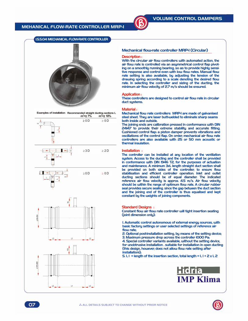
Description :With the circular air flow controllers with automated action, the air flow rate is controlled via an asymmetrical control flap pivot-ing on a smoothly running bearing, so as to provide highly sensi-tive response and control even with low flow rates. Manual flowrate setting is also available, by adjusting the tension of the drawing spring according to a scale denoting the desired flowrate. In selecting the controller and sizing of the ducting, theminimum air flow velocity of 2.7 m/s should be ensured.
Application :These controllers are designed to control air flow rate in circularduct systems.
Material :Mechanical flow rate controllers MRP-1 are made of galvanisedsteel sheet. They are laser butt-welded to eliminate sharp seamsboth inside and outside.The joining ends are calibration pressed in conformance with DIN24147 to provide their extreme stability and accurate fitting.Cushioned control flap: a piston damper prevents vibrations andoscillations of the control flap. On order, mechanical air flow ratecontrollers are also available with 25 or 50 mm acoustic or thermal insulation.
Installation :The controller can be installed at any location of the ventilationsystem. Access to the ducting and the controller shall be providedin conformance with DIN 1946 T2, for the purposes of actuation and maintenance. A minimum 3xL length straight duct section shallbe provided on both sides of the controller, to ensure flow stabilisation and efficient controller operation. Inlet and outlet ducting sections should be of equal diameter. The indicated reference air flow velocity is approx. 4.5 m/s. Air flow velocity should be within the range of optimum flow rate. A circular rubber seal provides secure sealing. since the gap between the duct section and the joining end of the controller is thus equalised and kept constant by the weights of joining components.
Standard Designs :Constant flow air flow rate controller will tight insertion seating(joint dimension only):
1. Automatic control autonomous of external energy sources, withbasic factory settings or user selected settings of reference airflow rate;2. Optional post-installation setting, by means of the setting device;3. Maximum pressure drop across the controller 1000 Pa;4. Special controller variants available, without the setting device,for unobtrusive installation . suitable for installation in open ducting(this design, however, does not allow flow rate setting afterinstallationi);5. L 1 = length of the insertion section, total length = L 1 + 2 x L 2
Mechanical flow-rate controller MRP-1 (Circular)
1.5.5.04 MECHANICAL FLOW-RATE CONTROLLER
Examples of installation Recommended straight ducting sections L2
m =+ 7%2
m =+ 10%
0 D 0 D> >
3 D 2 D> >
0 D 0 D> >
70
80-2
50
L2 L2L1
110
L2 L2L1
315-
400
MEHANICAL FLOW-RATE CONTROLLER MRP-1
VOLUME CONTROL DAMPERS
ALL DETAILS SUBJECT TO CHANGE WITHOUT PRIOR NOTICE

1.5.5.04 MECHANICAL FLOW-RATE CONTROLLER TECHNICAL SPECIFICATION
Nominal dimensionmm
Allowable air flow3range m /h;
Optimumair flow range Pa
Max. staticpressure drop
Pa
Recommendedduct air velocity
m/s
Dimension mm
Dimensions - air flow rate:
Diagram: static pressure drop resulting in the controller response:
300
250
200
150
100
50
0 2,0 3,0 4,0 5,0 6,0 7,0 8,0 9,0 10,C
p(P
a)
In sizing the air ducting, one shall observe theminimum pressure drop to result in the controllerresponse.
Air flow rate controller: type MRP-1Nominal length: ND 160Air flow velocity: 4.5 m/s
3Air flow rate: 325 m /hStatic prssure drop p in Pa, from thediagram 1:50 Pa
Calculation example:
Ordering Key:
MRP - 1 / Q / size 80, 100, 125, 140, 160, 200, 250, 315, 4003example: flow rate setting to 120 m /h
circular design1
80100125140160200250315400
4070
100140180250500600
1000
125200280400500900
150022003800
5075
120150200300480770
1240
108170265330430670
105019002850
100010001000100010001000100010001000
ca. 2,7 do 6,0ca. 2,7 do 6,0ca. 2,7 do 6,0ca. 2,7 do 6,0ca. 2,7 do 6,0ca. 2,7 do 6,0ca. 2,7 do 6,0ca. 2,7 do 6,0ca. 2,7 do 6,0
120170170170240240240220295
404040404040406060
min max min max L1 L2
VOLUME CONTROL DAMPERS
MECHANICAL FLOW-RATE CONTROLLER MRP-1
ALL DETAILS SUBJECT TO CHANGE WITHOUT PRIOR NOTICE

Description :Rectangular or square air flow controller is an autonomouscontrol component that maintains, within a defined range, aspecified constant air flow rate. The air flow rate is controlledvia a control flap pivoting on bearings on both sides, a systemof levers and a setting spring. The flap geometry ensures promptrespnse even under low pressure drops across the controller.The appropriate selection of the spring and the lever geometrylead to a defined correlation between the pressure drop and the position of the flap, thus maintaining a constant air flow rate.
Mechanical flow-rate controller MRP-2 (Rectangular)
Application :These controllers are designed to control air flow rate in rectan-gular duct systems. Their application temperature range is -20
Oto +110 C.. The controller operation starts at the minimumresponse pressure drop, which is a function of the air flow rate(Diagram2), and operates up to the maximum pressure drop of1000 Pa, in a stable control range. Across this operation rate.,the air flow rate deviations are limited to +10%. The controllercross section dimensions (width and height) should be selectedequal to the ducting dimensions in order to avoid mechanicaldeficiencies excessive pressure drops and increased operationnoises, Each flow rate controller is factory set to the flow raterequested by the customer. Within a certain range, the flow ratesetting can be changed, by means of the setting device.
The flow rate controller frame is made of galvanised steel sheet.The control flap is sated in special bearings made of PTFE forresistance against wear. To compensate any air flow oscillations,the controller is fitted by a damper fixed to the control flap,serving to damp any frequencies arising during fast openingor closing of the control flap. In this way, resonance vibrationsare avoided. The controller frame and connection parts conformto the sealing requirements for the angular components andclass C components of the prEN 1751 standard.
The controller can be easily installed in the ventilation system bymeans of its flange section. An important requirement is stablefixing of the ducting system to prevent oscillations of theducting in the flexible part during fast opening or closing of thecontrol flap. According to the general rules for the ventilationsystems, DIN 1946 Part 2(VDI rules for ventilation), access shallbe provided to the system ducting, for the purposes of adjustingand maintenance.
Material :
Installation :
1.5.5.04 MECHANICAL FLOW-RATE CONTROLLER
MEHANICAL FLOW-RATE CONTROLLER MRP-2
VOLUME CONTROL DAMPERS
A
B
H
30
ALL DETAILS SUBJECT TO CHANGE WITHOUT PRIOR NOTICE
-

7000
5000
3000
2000
1000
500
300
200
100
0,02 0,03 0,04 0,05 0,08 0,1 0,15 0,2
2A (m)
Existing system: air flow rate controllertype MRP-2Width: 400 mm, height: 200 mm
2(duct cross section: 0.08 m )Parameter to be determinded: air flow ratesetting range from diagram 1:
3V(3m/s)=865m /h
3V(10m/s)=2880m /h
Calculation example:
Existing system: air flow rate controllertype MRP-2Width: 250 mm, height: 200 mm
3Air flow rate 810 m /h(at air flow velocity 4.5 m/s)Parameter to be determined: staticPressure drop p in PaFrom the selection diagram: p = 80 Pa
Calculation example:
300
250
200
150
100
50
0
2 3 4 5 6 7 8 9 10 11
p (P
a)
Diagram 1: fast selection of air flow rate range according to the duct cross-section:
Diagram 2: Static prssure drop resulting in the controller response:
10 m/s3 m/s
Ordering Key:
MRP - 2 / Q / size B x H (example: 400 x 200)3
example: flow rate setting to 120 m /h
rectangular design2
150-330301-400200-350351-500250-400401-500501-600
150-200150-200201-250201-250251-300251-300251-300
385385420420460460460
3-103-103-103-103-103-103-10
1000100010001000100010001000
40404040404040
75957595959595
95959595959595
Width Bmm
Height Hmm
Length Lmm
Air flow velocity m/s Max. staticpressure drop Pa
Dimensions mm500 501-502 503-511
1.5.5.05 MECHANICAL FLOW-RATE CONTROLLER TECHNICAL SPECIFICATION
VOLUME CONTROL DAMPERS
MECHANICAL FLOW-RATE CONTROLLER MRP-2
v (m/s)
ALL DETAILS SUBJECT TO CHANGE WITHOUT PRIOR NOTICE
3Q
(m/h
)