בלשנות טכנולוגית באמצעות מאגרי מידע ואינטרנט נטליה גולצ'ר מאי 30, 2005.
Operating Instructions
Memory Card Camera-Recorder
Model No. AG-AF101E
M1210AT0 -FJVQT3M19A (E)
Before operating this product, please read the instructions carefully and save this manual for future use.
ENGLISH
Volume 2Note that Operation Instructions Vol.2 describes advanced operations of the Memory Card Camera-Recorder.For instructions on basic operations of the Memory Card Camera-Recorder, refer to Operating Instructions Vol.1 (printed documents) contained in the supplied CD-ROM.
Vol.2
This product is eligible for the AVCCAM 3 Year Warranty Repair Program. For details, see page E-5 of vol.1.
2
Contents
ShootingShooting in progressive mode ...................... 4Shooting techniques for different targets .... 5
Self-portrait shooting ........................................ 5Zebra pattern .................................................... 5Marker ............................................................... 6Checking and displaying shooting status .......... 6PRE REC .......................................................... 6Relay function .................................................... 6Variable frame rate (VFR).................................. 7Shooting using the FUNCTION knob .............. 10Optical Image Stabilizer .................................. 11Adding effects to images ................................. 11Using the USER buttons ................................ 11Backlight compensation .................................. 11Color bars ........................................................ 11Wave form monitor function ............................. 12Adjusting the volume while shooting ............... 12Shot mark function .......................................... 13Index recording ................................................ 13LAST CLIP function ......................................... 13CAPTURE function .......................................... 13
Adjusting the shutter speed ........................ 14Using the SHUTR/F.RATE dial ........................ 14Setting the SHUTTER ..................................... 14Setting the SYNCRO SCAN ............................ 14FRAME RATE setting ...................................... 14Synchro scan ................................................... 16
Switching Audio Input .................................. 17Using the built-in microphone .......................... 17Using an external microphone and audio
equipment .................................................... 17Adjusting the recording level ........................... 18
Using scene files .......................................... 19Changing scene file settings ........................... 19
Saving scene files and other settings on SD Memory Cards ........................................ 21
Clip metadata ................................................ 22Uploading the metadata (META DATA) ........... 23Selecting the USER CLIP NAME
recording method ........................................ 23Using the Counter ........................................ 24
Counter display ............................................... 24TC preset mode ............................................... 24
Volume 1
Read this first!Outline of operationsPlease read before useOperating precautions
Before usePrecaution for useAccessoriesOptional accessories
Description of partsDescription of parts
PreparationRecharging the batteryPower sourcesAdjusting the hand strapAttaching/detaching the handle
Attaching/detaching the gripThe remote controlTurn on/off the cameraTally lampViewfinderSetting the calendar
ShootingBasic shooting operationsBasic operations of the camera
MenuUsing the setup menusSetup menu structure
ReferenceSpecifications
Volume 2
3
Charging the built-in battery/ Setting the time code ........................... 25
Recharging the built-in battery ........................ 25Setting the time code ....................................... 25Specifying the time code (TC PRESET) .......... 25Setting user information .................................. 27
PlaybackBasic playback operations .......................... 28Thumbnail screen ......................................... 29
Basic thumbnail screen operations ................. 29Adding shot marks to clips .............................. 31Select the card slot for playback ..................... 31
Playback settings (PLAY SETUP)................ 32Set playback format (PB FORMAT)................. 32Repeat playback (REPEAT PLAY) .................. 32Resume playback (RESUME PLAY) ............... 33Set skip method (SKIP MODE) ....................... 33
Thumbnail operations .................................. 34Selecting the thumbnail display method
(THUMBNAIL) ............................................. 34Deleting and protecting clips (OPERATION) ... 35Copying clips (COPY) ..................................... 36Format card and check clip and
card information (CARD FUNCTIONS) ....... 37Useful playback functions ........................... 39
Fast forward/rewind ......................................... 39Next/previous clip ............................................ 39Frame-by-frame playback ............................... 40Adjust volume .................................................. 40Viewing images on a television ....................... 40Checking the date and time ............................. 40
EditingConnecting external units ........................... 41
Headphones .................................................... 41External microphone ....................................... 41Computer (non-linear editing/file transfer) ....... 42TV/Monitor ....................................................... 42
Nonlinear editing .......................................... 44
DisplaysScreen displays ............................................ 45
Regular displays .............................................. 45Main warning displays ..................................... 48Setting the DISPLAY items .............................. 50
MenuSetup menu list ............................................. 51
SCENE FILE screen ........................................ 51SW MODE screen ........................................... 53RECORDING SETUP screen .......................... 56TC/UB SETUP screen ..................................... 57AV IN/OUT SETUP screen .............................. 58DISPLAY SETUP screen ................................. 59CARD FUNCTIONS screen ............................ 61USER FILE screen .......................................... 61META DATA screen ......................................... 62OTHER FUNCTIONS screen .......................... 62PLAY SETUP screen ....................................... 64THUMBNAIL screen ........................................ 65OPERATION screen ........................................ 65
ReferenceBefore calling for service............................. 66Updating the firmware
incorporated into the unit .................... 70Cleaning ........................................................ 71Storage Precautions..................................... 72How to handle data recorded on
SD Memory Card ................................... 73
4
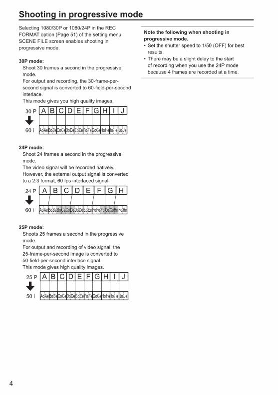
Shooting in progressive modeSelecting 1080/30P or 1080/24P in the REC FORMAT option (Page 51) of the setting menu SCENE FILE screen enables shooting in progressive mode.
30P mode: Shoot 30 frames a second in the progressive
mode. For output and recording, the 30-frame-per-
second signal is converted to 60-field-per-second interlace.
This mode gives you high quality images.
AoAeBoBeCoCeDoDeEoEe Fo FeGoGeHoHe Io Ie Jo Je
A B C D E F G H I J30 P
60 i
24P mode: Shoot 24 frames a second in the progressive
mode. The video signal will be recorded natively. However, the external output signal is converted
to a 2:3 format, 60 fps interlaced signal.
A B C D E F G H
AoAeBoBeBoCeCoDeDoDeEoEe FoFe Fo Ge GoHe Ho He
24 P
60 i
25P mode: Shoots 25 frames a second in the progressive
mode. For output and recording of video signal, the
25-frame-per-second image is converted to 50-field-per-second interlace signal.
This mode gives high quality images.
AoAeBoBeCoCeDoDeEoEe Fo FeGoGeHoHe Io Ie Jo Je
A B C D E F G H I J25 P
50 i
Note the following when shooting in progressive mode.
Set the shutter speed to 1/50 (OFF) for best •results.There may be a slight delay to the start •of recording when you use the 24P mode because 4 frames are recorded at a time.
5
Shoo
ting
Shooting techniques for different targetsSelf-portrait shooting
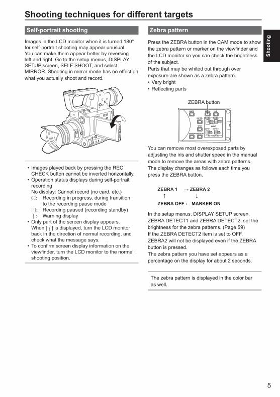
Images in the LCD monitor when it is turned 180° for self-portrait shooting may appear unusual.You can make them appear better by reversing left and right. Go to the setup menus, DISPLAY SETUP screen, SELF SHOOT, and select MIRROR. Shooting in mirror mode has no effect on what you actually shoot and record.
Images played back by pressing the REC •CHECK button cannot be inverted horizontally.Operation status displays during self-portrait •recording No display: Cannot record (no card, etc.)
: Recording in progress, during transition to the recording pause mode
: Recording paused (recording standby) : Warning display
Only part of the screen display appears. •When [ ] is displayed, turn the LCD monitor back in the direction of normal recording, and check what the message says.To confirm screen display information on the •viewfinder, turn the LCD monitor to the normal shooting position.
Zebra pattern
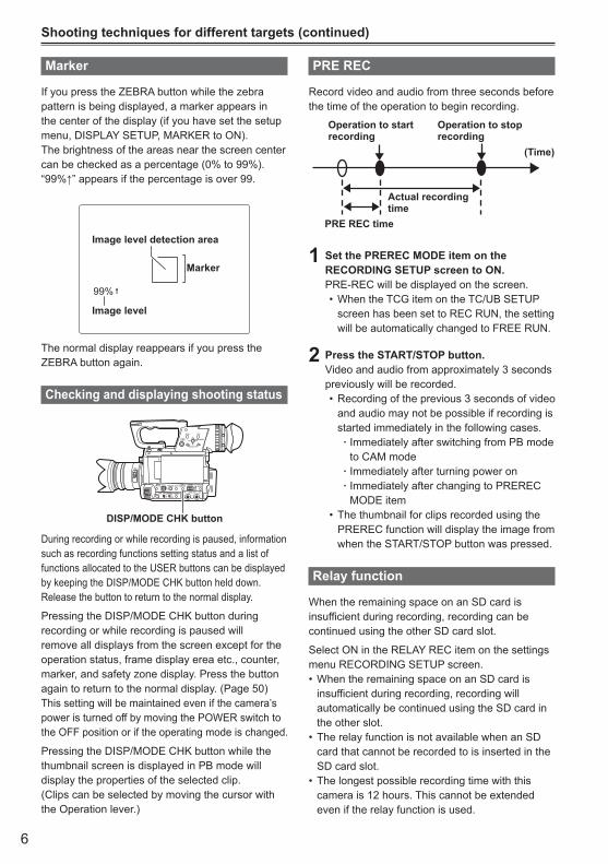
Press the ZEBRA button in the CAM mode to show the zebra pattern or marker on the viewfinder and the LCD monitor so you can check the brightness of the subject. Parts that may be whited out through over exposure are shown as a zebra pattern.
Very bright•Reflecting parts•
POWERFOCUS ..
BARS
EVF DTL CH1 SELINT(L)
ONOFF
ONOFF
INPUT1
AUDIO
MIC POWER +48V
INPUT1 INPUT2
INPUT2
INPUT1INPUT2
CH2 SEL
WFM
COUNTER-RESET/TC SET
ZEBRA OIS
ZEBRA button
You can remove most overexposed parts by adjusting the iris and shutter speed in the manual mode to remove the areas with zebra patterns.The display changes as follows each time you press the ZEBRA button.
ZEBRA 1 → ZEBRA 2 ↑ ↓ZEBRA OFF ← MARKER ON
In the setup menus, DISPLAY SETUP screen, ZEBRA DETECT1 and ZEBRA DETECT2, set the brightness for the zebra patterns. (Page 59)If the ZEBRA DETECT2 item is set to OFF, ZEBRA2 will not be displayed even if the ZEBRA button is pressed.The zebra pattern you have set appears as a percentage on the display for about 2 seconds.
The zebra pattern is displayed in the color bar as well.
6
Marker
If you press the ZEBRA button while the zebra pattern is being displayed, a marker appears in the center of the display (if you have set the setup menu, DISPLAY SETUP, MARKER to ON). The brightness of the areas near the screen center can be checked as a percentage (0% to 99%).“99%↑”appearsifthepercentageisover99.
99%
Image level detection area
Image level
Marker
The normal display reappears if you press the ZEBRA button again.
Checking and displaying shooting status
MENU
START/STOP 2 PUSH-ENTER
MODEPOWERDISP/
MODE CHKUSER 1
USER 2
FUNCTIONFOCUS
IRIS GAIN WHITE BALB
PUSH AUTO
MEGA
ON
OFF
O.I.S.
CAMON
CH1 CH2AUDIO LEVEL
..OFF
PB
+–
AUDIO MON
EXEC
APRST
LMH
AM∞
DISP/MODE CHK button
During recording or while recording is paused, information such as recording functions setting status and a list of functions allocated to the USER buttons can be displayed by keeping the DISP/MODE CHK button held down. Release the button to return to the normal display.
Pressing the DISP/MODE CHK button during recording or while recording is paused will remove all displays from the screen except for the operation status, frame display erea etc., counter, marker, and safety zone display. Press the button again to return to the normal display. (Page 50)This setting will be maintained even if the camera’s power is turned off by moving the POWER switch to the OFF position or if the operating mode is changed.
Pressing the DISP/MODE CHK button while the thumbnail screen is displayed in PB mode will display the properties of the selected clip. (Clips can be selected by moving the cursor with the Operation lever.)
Shooting techniques for different targets (continued)
PRE REC
Record video and audio from three seconds before the time of the operation to begin recording.
Operation to start recording
Operation to stop recording
Actual recording time
PRE REC time
(Time)
1 Set the PREREC MODE item on the RECORDING SETUP screen to ON.PRE-REC will be displayed on the screen.
When the TCG item on the TC/UB SETUP •screen has been set to REC RUN, the setting will be automatically changed to FREE RUN.
2 Press the START/STOP button.Video and audio from approximately 3 seconds previously will be recorded.
Recording of the previous 3 seconds of video •and audio may not be possible if recording is started immediately in the following cases.
Immediately after switching from PB mode āto CAM modeImmediately after turning power on āImmediately after changing to PREREC āMODE item
The thumbnail for clips recorded using the •PREREC function will display the image from when the START/STOP button was pressed.
Relay function
When the remaining space on an SD card is insufficient during recording, recording can be continued using the other SD card slot.
Select ON in the RELAY REC item on the settings menu RECORDING SETUP screen.
When the remaining space on an SD card is •insufficient during recording, recording will automatically be continued using the SD card in the other slot.The relay function is not available when an SD •card that cannot be recorded to is inserted in the SD card slot.The longest possible recording time with this •camera is 12 hours. This cannot be extended even if the relay function is used.
7
Shoo
ting
Variable frame rate (VFR)
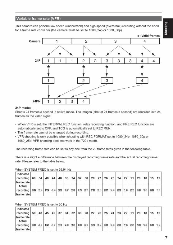
This camera can perform low speed (undercrank) and high speed (overcrank) recording without the need for a frame rate converter (the camera must be set to 1080_24p or 1080_30p).
Camera
24P
24PN
: Valid frames
24P mode:Shoots 24 frames a second in native mode. The images (shot at 24 frames a second) are recorded into 24 frames as the video signal.
When VFR is set, the INTERVAL REC function, relay recording function, and PRE REC function are •automatically set to OFF, and TCG is automatically set to REC RUN. The frame rate cannot be changed during recording.•VFR shooting is only possible when shooting with REC FORMAT set to 1080_24p, 1080_30p or •1080_25p. VFR shooting does not work in the 720p mode.
The recording frame rate can be set to any one from the 20 frame rates given in the following table.
There is a slight a difference between the displayed recording frame rate and the actual recording frame rate. Please refer to the table below.
When SYSTEM FREQ is set to 59.94 HzIndicated recording frame rate
60 54 48 44 40 36 34 32 30 28 27 26 25 24 22 21 20 18 15 12
Actual recording frame rate
59.94 53.74 47.54 43.96 39.96 35.97 33.88 31.73 29.97 27.83 27.25 25.97 24.98 23.98 21.98 20.75 19.98 17.63 14.99 11.99
When SYSTEM FREQ is set to 50 HzIndicated recording frame rate
50 48 45 42 37 34 32 30 28 27 26 25 24 23 22 21 20 18 15 12
Actual recording frame rate
50.00 48.08 45.45 41.67 36.76 34.09 31.82 30.00 27.78 26.79 26.04 25.00 24.00 23.08 22.06 20.83 20.00 17.86 15.00 12.50
8
Shooting techniques for different targets (continued)
Native recording
1 Select 1080/24P recording format from the REC FORMAT option (page 51) on the settings menu SCENE FILE screen.
2 From the OPERATION TYPE option (page 51) on the settings menu SCENE FILE screen, select FILM CAM, and set the FRAME RATE (page 51) to an arbitrary recording frame rate.
3 Press the START/STOP buttonStart native recording in VFR mode.
Although the audio is not recorded, the sound •is output from the AUDIO OUT terminal, HDMI terminal, and SDI OUT terminal during setup and during recording. During the VFR mode, the camera is set to •manual focus mode.
Standard recording
1 Select 1080/30P recording format from the REC FORMAT option (page 51) on the settings menu SCENE FILE screen.
2 From the OPERATION TYPE option (page 51) on the settings menu SCENE FILE screen, select FILM CAM, and set the FRAME RATE (page 51) to an arbitrary recording frame rate.
3 Press the START/STOP button.Start standard recording in VFR mode.
Although the audio is not recorded, the •sound is output from the AUDIO OUT terminal, HDMI terminal, and SDI OUT terminal during setup and during recording. During the VFR mode, the camera is set to •manual focus mode. 2:2 pull down recording will be applied for a •recording frame rate of 30P.
9
Shoo
ting
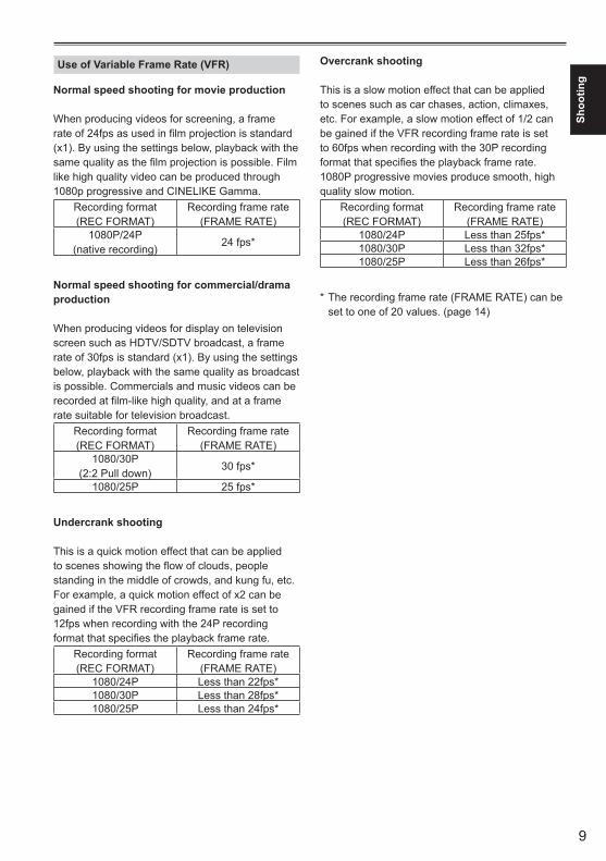
Use of Variable Frame Rate (VFR)
Normal speed shooting for movie production
When producing videos for screening, a frame rate of 24fps as used in film projection is standard (x1). By using the settings below, playback with the same quality as the film projection is possible. Film like high quality video can be produced through 1080p progressive and CINELIKE Gamma.
Recording format (REC FORMAT)
Recording frame rate (FRAME RATE)
1080P/24P (native recording)
24 fps*
Normal speed shooting for commercial/drama production
When producing videos for display on television screen such as HDTV/SDTV broadcast, a frame rate of 30fps is standard (x1). By using the settings below, playback with the same quality as broadcast is possible. Commercials and music videos can be recorded at film-like high quality, and at a frame rate suitable for television broadcast.
Recording format (REC FORMAT)
Recording frame rate (FRAME RATE)
1080/30P (2:2 Pull down)
30 fps*
1080/25P 25 fps*
Undercrank shooting
This is a quick motion effect that can be applied to scenes showing the flow of clouds, people standing in the middle of crowds, and kung fu, etc.For example, a quick motion effect of x2 can be gained if the VFR recording frame rate is set to 12fps when recording with the 24P recording format that specifies the playback frame rate.
Recording format (REC FORMAT)
Recording frame rate (FRAME RATE)
1080/24P Less than 22fps*1080/30P Less than 28fps*1080/25P Less than 24fps*
Overcrank shooting
This is a slow motion effect that can be applied to scenes such as car chases, action, climaxes, etc. For example, a slow motion effect of 1/2 can be gained if the VFR recording frame rate is set to 60fps when recording with the 30P recording format that specifies the playback frame rate. 1080P progressive movies produce smooth, high quality slow motion.
Recording format (REC FORMAT)
Recording frame rate (FRAME RATE)
1080/24P Less than 25fps*1080/30P Less than 32fps*1080/25P Less than 26fps*
* The recording frame rate (FRAME RATE) can be set to one of 20 values. (page 14)
10
Shooting techniques for different targets (continued)
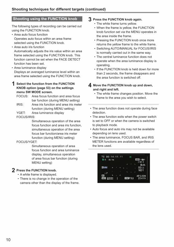
Shooting using the FUNCTION knob
The following types of recording can be carried out using the FUNCTION knob.
Area auto focus function• Operates auto focus within an area frame
selected using the FUNCTION knob.Area auto iris function•
Automatically adjusts the iris value within an area frame selected using the FUNCTION knob. This function cannot be set when the FACE DETECT function has been set. Area luminance display•
Displays an averaged luminance level within an area frame selected using the FUNCTION knob.
1 Select the function from the FUNCTION KNOB option (page 53) on the settings menu SW MODE screen.FOCUS: Area focus function and area focus
bar function (during MENU setting)IRIS: Area iris function and area iris meter
function (during MENU setting)YGET: Area luminance displayFOCUS/IRIS: Simultaneous operation of the area
focus function and area iris function, simultaneous operation of the area focus bar function/area iris meter function (during MENU setting)
FOCUS/YGET: Simultaneous operation of area
focus function and area luminance display, simultaneous operation of area focus bar function (during MENU setting)
2 Press the FUNCTION knob.A white frame is displayed.•There is no change in the operation of the •camera other than the display of the frame.
3 Press the FUNCTION knob again.The white frame turns yellow.•When the frame is yellow, the FUNCTION •knob function set via the MENU operates in the area inside the frame.Pressing the FUNCTION knob once more •returns the yellow frame to the white frame.Switching AUTO/MANUAL for FOCUS/IRIS •is normally carried out in the same way.The central luminance function does not •operate when the area luminance display is operating.If the FUNCTION knob is held down for more •than 2 seconds, the frame disappears and the area function is switched off.
4 Move the FUNCTION knob up and down, and right and left.
The white frame changes position. Move the •frame to the area you wish to select.
The area function does not operate during face •detection.The area function exits when the power switch •is set to OFF or when the camera is switched to playback mode. Auto focus and auto iris may not be available •depending on lens used.The area luminance, FOCUS BAR, and IRIS •METER functions are available regardless of the lens used.

11
Shoo
ting
Optical Image Stabilizer
Use the Optical Image Stabilizer (OIS) to reduce the effects of camera shake when shooting by hand.Press the OIS button to turn the function on and off. appears on the viewfinder and the LCD monitor when this function is on. Turn the function off when using a tripod for more natural images.
POWERFOCUS ..
BARS
EVF DTL CH1 SELINT(L)
ONOFF
ONOFF
INPUT1
AUDIO
MIC POWER +48V
INPUT1 INPUT2
INPUT2
INPUT1INPUT2
CH2 SEL
WFM
COUNTER-RESET/TC SET
ZEBRA OIS
For lenses that have an OIS button, only the lens •button is active and the button on the camera is deactivated. Also, some lenses do not have an OIS function.This function will not be as effective when the •vibration is severe or when tracking a moving subject.
Adding effects to images
Press the USER button you have allocated to the BLACKFADE or WHITEFADE feature to add fading effects to your images. The button’s function is forcibly canceled during playback or REC CHECK and also when thumbnails are displayed.
BLACKFADE: Press the button to fade out to black. Audio also
fades out. Fade-in starts after fade-out, when the button is released.
WHITEFADE: Press the button to fade out to white. Audio also
fades out. Fade-in starts after fade-out, when the button is released.
Using the USER buttons
You can allocate one of thirteen features to each of the three USER buttons. Use these buttons to change shooting settings quickly or add effects to the images you are shooting. The following features are allocated to the buttons at the time of shipping. USER1: FA USER2: ATW LOCK USER3: REC CHECKFor details, see the setup menus, SW MODE screen, USER1 SW to USER3 SW. (Page 55)If you press a USER button to which one of the functions has been assigned, and then turn OFF the power or change the mode during operation of the USER button function, the effect added to the image will not be retained.
Backlight compensation
Press the USER button you have allocated to the BACKLIGHT feature when shooting subjects lit from the back.BACK appears on the screen. Backlight compensation adjusts the iris so the subject doesn’t come out dark.Press the same USER button to turn the feature off. (In the manual iris mode, the iris status is retained at the corresponding point even when backlight compensation is canceled.)
The backlight compensation function does not •operate with lenses in which AUTO IRIS is not functioning.
Color bars
Press the BARS button in the CAM mode to output a color bar screen to a television or monitor so you can adjust them. Press the button again to turn the feature off.
While the color bar is displayed, a test tone of •1 kHz will be output from the headphone terminal or the AUDIO OUT terminal. There will be no speaker output.The color bar can be recorded by pressing the •START/STOP button.The color bar display is canceled when the power •is turned off.

12
Shooting techniques for different targets (continued)
Wave form monitor function
An image wave form can be displayed on the LCD monitor by pressing the WFM button while in CAM mode.Press the button again to return to the normal display.
Switching the wave form display, vector display, •and wave/vector display is possible from the WFM item (page 55) in the SW MODE screen of the settings menu. Wave forms will not be displayed in the •viewfinder.Wave forms cannot be recorded.•While wave forms are displayed, use the •viewfinder as well because a part of the recording screen and screen display will be hidden by wave forms.
Adjusting the volume while shooting
MENU
START/STOP 2 PUSH-ENTER
MODEPOWERDISP/
MODE CHKUSER 1
USER 2
FUNCTIONFOCUS
IRIS GAIN WHITE BALB
PUSH AUTO
MEGA
ON
OFF
O.I.S.
CAMON
CH1 CH2AUDIO LEVEL
..OFF
PB
+–
AUDIO MON
EXEC
APRST
LMH
AM∞
Adjusting the volume
AUDIO MON/ADV
If you are monitoring the sound through headphones while shooting, you can adjust the volume with the AUDIO MON/ADV buttons.
To adjust the recording level. (Page 18)•Volume adjustments will be memorized if the •power is turned off by moving the POWER switch to the OFF position.

13
Shoo
ting
Shot mark function
The marks attached to the thumbnails of clips are called shot marks. On the thumbnail screen monitor you can select only those clips with a shot mark and display them or play them back.During recording, when you press the USER button to which the SHOT MARK function has been allocated, MARK ON appears in the LCD monitor or the viewfinder, and a shot mark is set for the thumbnail of the clip being recorded. If you press the button again, the shot mark is released.You can also set or release the shot marks by performing the thumbnail operations for clips. (Page 31)However, note that you cannot set or release shot marks during playback.
INVALID appears when you cannot set or release •shot marks.
Index recording
This function allows you to add an index at a certain point of a clip during the recording or playback.Press the USER button allocated to the INDEX function during recording to record an index signal at this point of the clip. (Pages 11, 55)Indexes may also be added during playback, and it is also possible to select only clips with indexes for display or playback. (Pages 34, 35)
Up to 100 indexes can be recorded for one •clip.When the number of indexes exceeds 100, •INVALID is displayed, and no further indexes can be added even when the steps for adding indexes are taken.When repeatedly adding indexes, leave a gap •of at least one second between adding one index and the next. If indexes are added with a gap of less than one second between them, only the first operation will be valid.
LAST CLIP function
The most recently recorded clip can be deleted at the touch of a button by allocating the LAST CLIP function to any of the USER 1 - 3 buttons.Press the USER button allocated for the LAST CLIP function to display YES/NO on the screen.Select YES to delete the most recently recorded clip.
Select NO not to delete the clip.•If the camera has been switched to PB mode or •the recording format has been changed since recording was completed, clips cannot be deleted even if the button is pressed. Clips also cannot be deleted if the power has been switched off and back on again.Clips cannot be deleted even if the button is •pressed if the memory card has been removed and reinserted since recording was completed.
CAPTURE function
If the CAPTURE feature is assigned to any of the USER 1 – 3 buttons, still images can be shot.
The number of recorded pixels and quality of •the still images cannot be changed. This function does not operate when a movie •is being recorded, or when the PRE REC mode is in use. The SD memory card used for recording is the •same as that used for video recording.

14
Using the SHUTR/F.RATE dial
DIAL SELECT button
SHUTR/F.RATE dial
Press the DIAL SELECT button.The role of the SHUTR/F.RATE dial changes in •the following order. SHUTTER→SYNCROSCAN→FRAMERATE→DIALLOCK→SHUTTER→SYNCRO SCAN can be selected when the •SHUTTER is set to SYNCRO SCAN. FRAME RATE can be selected in the FILM CAM mode when the REC FORMAT is 1080/24P, 30P, and 25P.
To prevent incorrect operation, it is recommended that you selecting DIAL LOCK using the DIAL SELECT button after setting.
Setting the SHUTTER
1 Select the SHUTTER function with the DIAL SELECT button.
2 Press the SHUTR/F.RATE dial.The shutter will turn ON/OFF.•The shutter speed is changed in the order •shown on the following page by turning the SHUTR/F.RATE dial when the shutter is ON.
Remember that the faster the shutter speed, •the lower the sensitivity. Focusing on the subject would take longer if •the shutter speed is reduced. It is therefore recommended that the unit be secured to a tripod, etc. during shooting. Under the lighting of electric discharge tubes •such as fluorescent lamps, horizontal bands may appear on the screen. Adjusting the shutter speed may improve this condition. A subject that quickly crosses the camera may •appear distorted when shot. This is caused due to the signal reading system of the imaging element (MOS sensor), and is not a defect. At slow shutter speeds (1/2 to 1/15), white, •red, green, or blue dots may appear on the screen. However, this is not a defect.
Setting the SYNCRO SCAN
1 Select SYNCRO SCAN from the SHUTTER settings.
2 Select the SYNCRO SCAN function with the DIAL SELECT button.
3 Turn the SHUTR/F.RATE dial.The SYNCRO SCAN shutter speed can be •set.The speed of change increases when turning •the SHUTR/F.RATE while holding it down.SYNCRO SCAN can also be set from the •SYNCRO SCAN item in the SCENE FILE screen of MENU settings.
Setting format differs depending on the MENU-SCENE FILE-OPERATION TYPE.FILM CAM: angle display (180.0d etc.)VIDEO CAM: speed display (1/48.0 etc.)
FRAME RATE setting
1 Select the FRAME RATE function with the DIAL SELECT button.
2 Press the SHUTR/F.RATE dial.The camera is in VFR mode.
The FRAME RATE can be set by turning the •SHUTR/F.RATE dial.FRAME RATE can also be set from the •FRAME RATE item in the SCENE FILE screen of MENU settings.
Before using the FRAME_RATE function, it •is necessary for the MENU-SCENE FILE-OPERATION TYPE to be set to FILM CAM, and the MENU-SCENE FILE-REC FORMAT to be set to PH1080/24P or PH1080/30P (or PH1080/25P).The FRAME RATE function cannot be set •when SDI 24PsF is set to ON in the AV IN/OUT SETUP screen of MENU settings. When the FRAME RATE function is set to •ON, the camera is automatically set to manual focus.
Adjusting the shutter speed
15
Shoo
ting
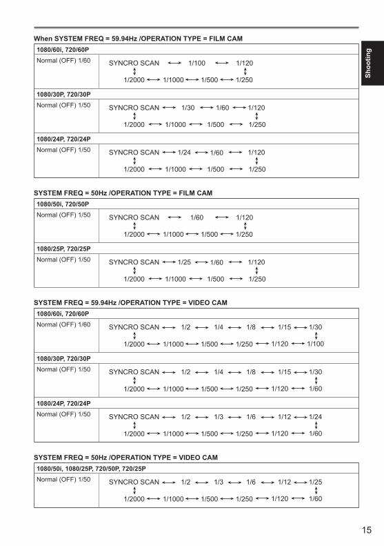
When SYSTEM FREQ = 59.94Hz /OPERATION TYPE = FILM CAM1080/60i, 720/60PNormal (OFF) 1/60 SYNCRO SCAN 1/100 1/120
1/2000 1/1000 1/500 1/250
1080/30P, 720/30PNormal (OFF) 1/50 SYNCRO SCAN 1/30 1/60 1/120
1/2000 1/1000 1/500 1/250
1080/24P, 720/24PNormal (OFF) 1/50 SYNCRO SCAN 1/24 1/120
1/2000 1/1000 1/500 1/250
1/60
SYSTEM FREQ = 50Hz /OPERATION TYPE = FILM CAM1080/50i, 720/50PNormal (OFF) 1/50 SYNCRO SCAN 1/60 1/120
1/2000 1/1000 1/500 1/250
1080/25P, 720/25PNormal (OFF) 1/50 SYNCRO SCAN 1/25 1/120
1/2000 1/1000 1/500 1/250
1/60
SYSTEM FREQ = 59.94Hz /OPERATION TYPE = VIDEO CAM1080/60i, 720/60PNormal (OFF) 1/60 SYNCRO SCAN 1/30
1/2000 1/1000 1/500 1/250 1/120 1/100
1/2 1/4 1/8 1/15
1080/30P, 720/30PNormal (OFF) 1/50 SYNCRO SCAN 1/30
1/2000 1/1000 1/500 1/250 1/120 1/60
1/2 1/4 1/8 1/15
1080/24P, 720/24PNormal (OFF) 1/50 SYNCRO SCAN 1/24
1/2000 1/1000 1/500 1/250 1/120 1/60
1/2 1/3 1/6 1/12
SYSTEM FREQ = 50Hz /OPERATION TYPE = VIDEO CAM1080/50i, 1080/25P, 720/50P, 720/25PNormal (OFF) 1/50 SYNCRO SCAN 1/25
1/2000 1/1000 1/500 1/250 1/120 1/60
1/2 1/3 1/6 1/12
16
Synchro scan
The syncro scan shutter speed used when shooting screens such as a TV screen or computer monitor is set using the SHUTR/F RATE dial (page 14) or the SYNCRO SCAN option on the settings menu SCENE FILE screen. (page 51)
Adjust the shutter speed to match the frequency •of the television or computer monitor to minimize the horizontal noise that appears when shooting such subjects.By switching to progressive mode you can also •shoot PAL system television screens.If the set value of the SYNCRO SCAN item of •settings menu is displayed in gray, it cannot be used with the current recording format. This function will only operate for preset values for each recording format, as listed below.
60i/60P mode: 1/60 30P mode: 1/30
You can change the progressive mode in the setup menu with REC FORMAT in the SCENE FILE screen. (Page 51)
Adjusting the shutter speed (continued)

17
Shoo
ting
During shooting, you can record up to two channels of sound. You can also switch the input sound to be recorded on each of the channels to the built-in microphones, external microphones or audio equipment connected to camera.
POWERFOCUS ..
BARS
EVF DTL CH1 SELINT(L)
ONOFF
ONOFF
INPUT1
AUDIO
MIC POWER +48V
INPUT1 INPUT2
INPUT2
INPUT1INPUT2
CH2 SEL
WFM
COUNTER-RESET/TC SET
ZEBRA OIS
CH1 SELECT switch
CH2 SELECT switch
INPUT 1/2 (MIC POWER +48V) switches
INPUT 1 switch INPUT 2 switch
INPUT 1 terminal INPUT 2 terminal
Switching Audio InputUsing the built-in microphone
1 Switch the CH1 SELECT switch to INT (L).Audio from the built-in microphone Lch is •recorded to audio channel 1.
2 Switch the CH2 SELECT switch to INT (R).Audio from the built-in microphone Rch is •recorded to audio channel 2.
Using an external microphone and audio equipment
1 Connect an external microphone or audio equipment to the INPUT 1/2 (XLR 3-pin) terminals. (Page 41)
2 Use the INPUT 1/2 switches to switch the audio input.LINE: (audio equipment is connected) Input level is 0 dBu.MIC: (an external microphone is connected) Input level is -50 dBu.
You can change the input level to -60 dBu in the setup menus, RECORDING SETUP screen MIC GAIN1 and MIC GAIN2. (Page 56) Be aware that sensitivity will be higher if you choose -60 dBu so you will record more noise.
3 When using the phantom microphone (which requires + 48V power supply),set the INPUT 1/2 (MIC POWER +48V) switches to ON.ON: (When using the phantom microphone) +48V power supply to INPUT 1/2 terminals.OFF: (When a phantom microphone is not
connected) No power supply for INPUT 1/2 terminals.
The battery will discharge faster if you use a •phantom microphone.Set to OFF if you connect equipment not •compatible with +48V. You can damage such equipment if you leave the setting at ON.When using the AG-MC200G (optional), set •the MIC GAIN item to -50 dBu.
18
Adjusting the recording level
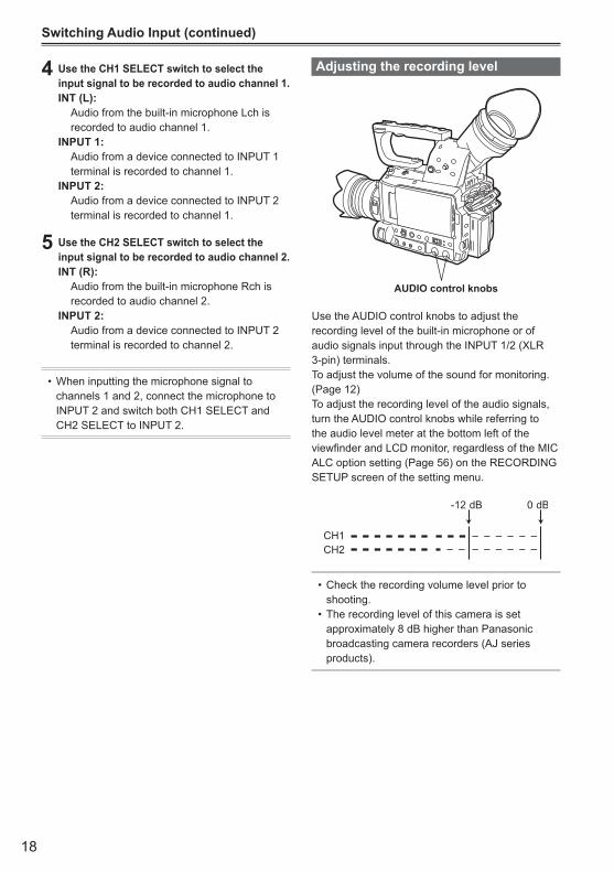
AUDIO control knobs
Use the AUDIO control knobs to adjust the recording level of the built-in microphone or of audio signals input through the INPUT 1/2 (XLR 3-pin) terminals. To adjust the volume of the sound for monitoring. (Page 12)To adjust the recording level of the audio signals, turn the AUDIO control knobs while referring to the audio level meter at the bottom left of the viewfinder and LCD monitor, regardless of the MIC ALC option setting (Page 56) on the RECORDING SETUP screen of the setting menu.
Check the recording volume level prior to •shooting.The recording level of this camera is set •approximately 8 dB higher than Panasonic broadcasting camera recorders (AJ series products).
Switching Audio Input (continued)
4 Use the CH1 SELECT switch to select the input signal to be recorded to audio channel 1.INT (L): Audio from the built-in microphone Lch is
recorded to audio channel 1.INPUT 1: Audio from a device connected to INPUT 1
terminal is recorded to channel 1.INPUT 2: Audio from a device connected to INPUT 2
terminal is recorded to channel 1.
5 Use the CH2 SELECT switch to select the input signal to be recorded to audio channel 2.INT (R): Audio from the built-in microphone Rch is
recorded to audio channel 2.INPUT 2: Audio from a device connected to INPUT 2
terminal is recorded to channel 2.
When inputting the microphone signal to •channels 1 and 2, connect the microphone to INPUT 2 and switch both CH1 SELECT and CH2 SELECT to INPUT 2.

19
Shoo
ting
Using scene filesThe settings according to the variety of shooting circumstances are stored SCENE FILE MENU.They are selected via the SCENE SELECT on the settings menu SCENE FILE screen.
When the camera-recorder is shipped from the factory, the following files are stored.
F1: File suitable for normal shooting.F2: FLUO. File suitable for shooting under fluorescent
lights, ie. indoors.F3: SPARK File suitable for shooting with fuller variations
of resolution, coloring and contrast.F4: B-STR File for broadening the contrast of dark parts,
such as when shooting sunsets.F5: CINE V File suitable for shooting movie-like scenes
where the contrast is to be emphasized. (The recording format remains unchanged even when the scene file is changed. It must be set using the REC FORMAT item on the SCENE FILE screen. (Page 51))
F6: CINE D File suitable for shooting movie-like
scenes where the dynamic range is to be emphasized. (The recording format remains unchanged even when the scene file is changed. It must be set using the REC FORMAT item on the SCENE FILE screen. (Page 51))
Changing scene file settings
The setting value of the scene file can be changed. Also you can save the changed scene file to each position of the SCENE FILE dial.
Example: Change the name of the scene file.
1 Set the POWER switch to ON.
2 Select the scene file to be changed in the SCENE FILE MENU.
3 In the setup menus, select the SCENE FILE screen.
For menu operation (Page E-44 of Vol.1)•Operations may also be performed •using buttons on the remote control that correspond to those on the camera. For details, see “Description of parts (Remote control)”.(PageE-23ofVol.1)
4 Tilt the Operation lever in the directions and select the NAME EDIT item.
5 Push the Operation lever (or tilt in the direction), tilt in the direction to select YES, and push the Operation lever again.

20
6 Set a 6-character filename with the Operation lever when the following screen is displayed.Set the same as user information. (Page 27)
Characters that can be set• Space, A to Z, 0 to 9, : ; < = > ? @ [ ] ^_-./
If the RESET/TC SET button is pressed when the filename has been set, the characters are cleared.
7 After you finish setting the filename, push the Operation lever.
8 Select YES on the confirmation screen.Selecting YES will close the NAME EDIT •screen and confirm all changes.Once confirmed, all changed names and •values will be saved even if the power is switched off or the scene dial is moved.
Using scene files (continued)
21
Shoo
ting
Saving scene files and other settings on SD Memory Cards
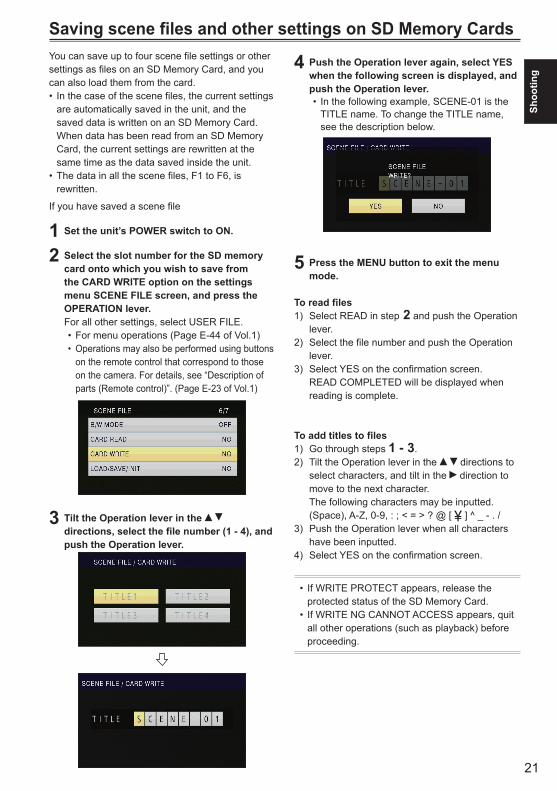
4 Push the Operation lever again, select YES when the following screen is displayed, and push the Operation lever.
In the following example, SCENE-01 is the •TITLE name. To change the TITLE name, see the description below.
5 Press the MENU button to exit the menu mode.
To read files1) Select READ in step 2 and push the Operation
lever.2) Select the file number and push the Operation
lever.3) Select YES on the confirmation screen. READ COMPLETED will be displayed when
reading is complete.
To add titles to files1) Go through steps 1 - 3.2) Tilt the Operation lever in the directions to
select characters, and tilt in the direction to move to the next character. The following characters may be inputted. (Space), A-Z, 0-9, : ; < = > ? @ [ ] ^ _ - . /
3) Push the Operation lever when all characters have been inputted.
4) Select YES on the confirmation screen.
If WRITE PROTECT appears, release the •protected status of the SD Memory Card.If WRITE NG CANNOT ACCESS appears, quit •all other operations (such as playback) before proceeding.
You can save up to four scene file settings or other settings as files on an SD Memory Card, and you can also load them from the card.
In the case of the scene files, the current settings •are automatically saved in the unit, and the saved data is written on an SD Memory Card. When data has been read from an SD Memory Card, the current settings are rewritten at the same time as the data saved inside the unit.The data in all the scene files, F1 to F6, is •rewritten.
If you have saved a scene file
1 Set the unit’s POWER switch to ON.
2 Select the slot number for the SD memory card onto which you wish to save from the CARD WRITE option on the settings menu SCENE FILE screen, and press the OPERATION lever.For all other settings, select USER FILE.
For menu operations (Page E-44 of Vol.1) •Operations may also be performed using buttons •on the remote control that correspond to those on the camera. For details, see “Description of parts(Remotecontrol)”.(PageE-23ofVol.1)
3 Tilt the Operation lever in the directions, select the file number (1 - 4), and push the Operation lever.
22
You can add the video and audio systems, name of the videographer, shooting location, text memos and other information to the video data you have recorded on the SD Memory Card. This data is called the clip metadata.(Display method: Page 38)
There are two kinds of clip metadata: the data that is recorded automatically during shooting, and the data in the metadata upload file created on the SD Memory Card which is loaded in the unit. (Loading method: Next page)
What the clip metadata consists of
You can set the items underlined below by loading the metadata upload file on the SD Memory Card. All other items are set automatically during shooting.
GLOBAL CLIP ID: This indicates the global clip ID that shows the
shooting status of the clip.USER CLIP NAME : This indicates the name of the clip that the user
has set.∗1
VIDEO & AUDIO: This indicates the recorded image’s FRAME
RATE, RESOLUTION, PULL DOWN system and AUDIO.
LENS: This indicates the MAKER, MODEL, and
SERIAL No. of your lens.ACCESS: This indicates the CREATOR (name of the
person recording), CREATION DATE (recording date), LAST UPDATE DATE (date on which the data was last updated) and LAST UPDATE PERSON (the person who last updated the data).
DEVICE: This indicates the MANUFACTURER
(manufacturer of the equipment), SERIAL NO. (serial number of the equipment) and MODEL NAME (Equipment model name: AG-AF100 for this camera-recorder).
SHOOT: This indicates the SHOOTER (name of the
videographer) and the PLACE NAME (name of location).
LOCATION: This indicates ALTITUDE, LONGITUDE,
LATITUDE, and SOURCE (altitude, longitude, latitude, information source). Not recorded in this camera-recorder.
SCENARIO:∗2
This indicates the PROGRAM NAME, SCENE NO. and TAKE NO.NEWS 1: This indicates the REPORTER (name of the
reporter) and PURPOSE (purpose of data collection).
NEWS 2: This indicates the OBJECT (target of data
collection).MEMO:∗3
This indicates the PERSON (name of the person who recorded the text memo) and TEXT (contents of memo).
∗1 If there is no information in the metadata upload file, consecutive five-digit numbers will be applied to the clips in the order that they were recorded, with the first clip to be recorded being given the number 0. The USER CLIP NAME recording method is selectable. Please refer to the page 23.
∗2 When SCENARIO is to be input, you must input the PROGRAM NAME. You cannot input the SCENE NO. and TAKE NO. only.
∗3 When MEMO is to be input, you must input TEXT. You cannot input PERSON only.
Only printable ASCII characters can be •displayed by this unit.Due to the limitations imposed by this unit •on the number of characters which can be displayed, not all the data can be displayed. (This does not mean that the data which is not displayed has been deleted.) Use an AVCCAM viewer or other program to check all the data.Metadata can be produced with AVCCAM •Viewer. (Page 73)
Clip metadata
23
Shoo
ting
Uploading the metadata (META DATA)
You can perform any of the following operations. If necessary, make preparations prior to undertaking the operations.
Loading the metadataInsert the SD Memory Card on which the •metadata is recorded into the unit. (For details on contents of the metadata, see the previous page.)
Selecting whether to record the metadata on the SD Memory CardInitializing the metadata inside the unitDisplaying the metadata inside the unit
1 Press the mode button and select CAM mode.
2 Press the MENU button.Menu operation (Page E-44 of Vol.1)
3 Tilt the lever in the directions to select META DATA, and push the Operation lever (or tilt in the direction).
4 Tilt the Operation lever in the directions to select item, and push the Operation lever.
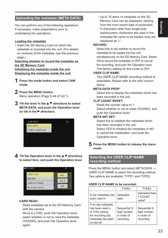
CARD READ: Read metadata set to the SD Memory Card
with the camera. Move to LOAD, push the Operation lever, select whether or not to read the metadata (YES/NO), and push the Operation lever again.
Up to 10 items of metadata on the SD āMemory Card can be displayed, starting from the most recent date of production.If characters other than single-byte āalphanumeric characters are used in the metadata file name to be loaded, they are displayed as “∗”.
RECORD: Select this to set whether to record the
metadata to be loaded into the unit simultaneously on the SD Memory Card. Select ON to record the metadata or OFF to cancel the recording, and push the Operation lever. The factory setting for this mode is OFF.
USER CLIP NAME: The USER CLIP NAME recording method is
selectable. Please refer to the next column below.
META DATA PROP: Select this to display the metadata which has
been recorded in the unit.CLIP COUNT RESET: Reset the counter value to 1. Select whether or not to reset (YES/NO), and
push the Operation lever.META INIT SET: Select this to initialize the metadata which
has been recorded in the unit. Select YES to initialize the metadata or NO to cancel the initialization, and push the Operation lever.
5 Press the MENU button to release the menu mode.
Selecting the USER CLIP NAME recording method
PresstheMENUbuttonandselectMETADATA→USER CLIP NAME to select the recording method. Two options are available: TYPE1 and TYPE2.
USER CLIP NAME to be recordedTYPE1 TYPE2
If clip metadata has been read in
Uploaded data
Uploaded data + COUNT value∗
If no clip metadata has been read in or if the setting for recording clip metadata has been turned off
Sequential 5-digit number, in order of recording
Sequential 5-digit number, in order of recording

24
Clip metadata (continued)
Using the CounterCounter display
You can display a counter that indicates how much time has elapsed during shooting or playback.
1 Press the COUNTER button.Each time you press the button, the display changes as follows. (Page 45)0 : 00. 00 (CAM mode only) Counter value Displayed when TOTAL is selected from
the REC COUNTER item in the DISPLAY SETUP screen of MENU settings.
CLIP 0 : 00 . 00 Displayed when CLIP is selected in the
REC COUNTER item on the settings menu DISPLAY SETUP screen.
Values are automatically reset when recording is started, and counter values are displayed for each individual clip.
TC 12 : 34 : 56 . 01 Time code value (Display time code frame
digits in 24 frames when 24P is set, and in 30 frames when any other format is set.)
UB 12 34 56 78 User informationNo display: Data is not displayed.
TC preset mode
When shooting using a multi-camera, you can synchronously set the initial values of time code. The camera used for synchronization is the MASTER and the camera being synchronized is the SLAVE.
1 Connect the TC PRESET IN/OUT terminals (VIDEO OUT terminals) on the two devices with a pin cable, and turn on the power.
MASTER settings ■2 Check that the MASTER camera is set to the
CAM mode, and set the EXT TC LINK item on the setting menu TC/UB SETUP screen to MASTER. OUTPUTTING LTC SIGNAL is displayed on the screen, and the time code is output from the TC PRESET IN/OUT terminal (VIDEO OUT terminal).
Select the same REC FORMAT setting for •both the MASTER and SLAVE cameras, and set the TCG item on the TC/UB SETUP screen to FREE RUN.To cancel the time code output, press the •MENU button.
SLAVE settings ■3 Set the EXT TC LINK item on the setting
menu TC/UB SETUP screen to SLAVE.
4 Press the COUNTER - RESET/TC SET button. TCG values will be reset to the TC values inputted from the MASTER.
TC LINK OK will be displayed for •approximately 2 seconds when the menu screen is closed.If the TC values cannot be set correctly, LINK •NG will be displayed.If the SLAVE device is set to 24P, please set •the TC MODE item on the MASTER device to NDF.To cancel the SLAVE mode, press the MENU •button.
∗ The COUNT value is indicated as a four-digit number. The COUNT value is incremented each time a new clip is captured if clip metadata has been read in and TYPE2 has been selected as the recording method. The COUNT value can be reset using the following procedure. PresstheMENUbutton,selectMETADATA→CLIPCOUNTRESET→YES,andpushtheOperation lever to reset the counter value to 1.
25
Shoo
ting
Recharging the built-in battery
The camera’s internal battery saves the date and time. When LOW INTERNAL BATTERY (indicating that the internal battery has no remaining charge) is displayed even when the date and time are set, it means that the charge of the internal battery is depleted. Do the following to recharge it.Reset the date and time when fully recharged.
1 Connect the AC adaptor. (Page E-25 of Vol.1)Leave the POWER switch at OFF.•
2 Leave the camera-recorder like this for about 4 hours.
The internal battery charges during this time.•Check the time code and menu operations •after recharging.
If the date and time are not memorized after recharging, the internal battery requires changing. Please consult the place of purchase.
Setting the time code
In the setup menus, TC/UB SETUP screen, set the following time code related items. (Page 57)
TC MODE•TCG•TC PRESET•
Charging the built-in battery/Setting the time codeSpecifying the time code (TC PRESET)
Set TC PRESET so you can record a value of your choice as the initial setting for the time code to be used at the start of recording.
1 Set the POWER switch to ON.
2 Select the TC PRESET item in the settings menu TC/UB SETUP screen.
For menu operation (Page E-44 of Vol.1)•Operations may also be performed •using buttons on the remote control that correspond to those on the camera. For details, see “Description of parts (Remote control)”.(PageE-23ofVol.1)
3 Tilt the Operation lever in the direction to move to YES, and push the Operation lever.
26
With this unit, the time code value is adjusted in accordance with the format and frame rate. For this reason, bear in mind that making a change in the format or frame rate may result in discontinuity from the last time code value of the previous recording.Adjustments are made in 4-frame increments when the recording format is 24P.
Recording format Time codeadjustment
1080/24P720/24P
Adjustable in4-frame increments
Charging the built-in battery/Setting the time code (continued)
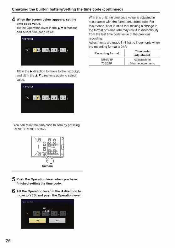
4 When the screen below appears, set the time code value.Tilt the Operation lever in the directions and select time code value.
Tilt in the direction to move to the next digit, and tilt in the directions again to select value.
You can reset the time code to zero by pressing RESET/TC SET button.
POWERFOCUS ..
BARS
EVF DTL CH1 SELINT(L)
ONOFF
ONOFF
INPUT1
AUDIO
MIC POWER +48V
INPUT1 INPUT2
INPUT2
INPUT1INPUT2
CH2 SEL
WFM
COUNTER-RESET/TC SET
ZEBRA OIS
Camera
5 Push the Operation lever when you have finished setting the time code.
6 Tilt the Operation lever in the direction to move to YES, and push the Operation lever.
27
Shoo
ting
Play
back
Setting user information
Setting user information allows you to store 8-digitinformation in the hexadecimal format.User information is automatically saved in the memory and retained after you turn off the power.
1 Set the POWER switch to ON.
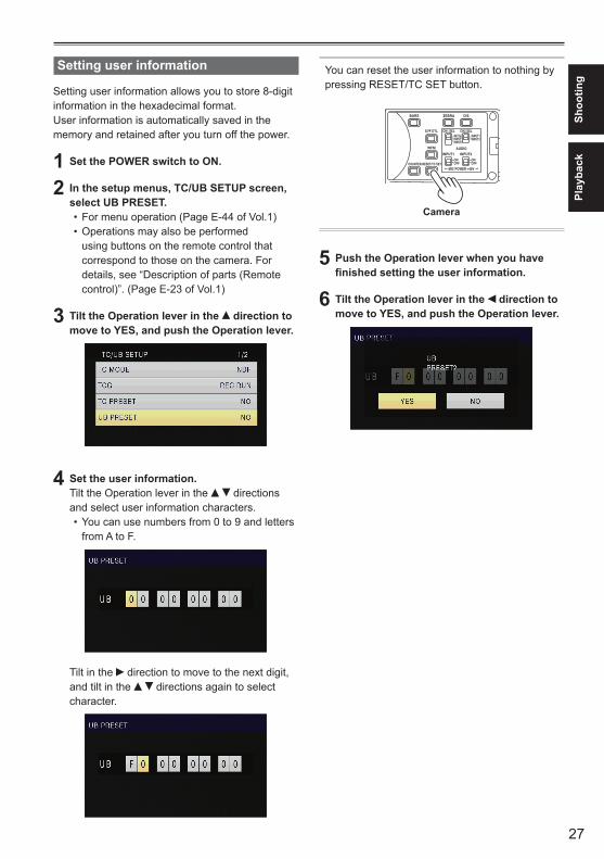
2 In the setup menus, TC/UB SETUP screen, select UB PRESET.
For menu operation (Page E-44 of Vol.1)•Operations may also be performed •using buttons on the remote control that correspond to those on the camera. For details, see “Description of parts (Remote control)”.(PageE-23ofVol.1)
3 Tilt the Operation lever in the direction to move to YES, and push the Operation lever.
4 Set the user information. Tilt the Operation lever in the directions and select user information characters.
You can use numbers from 0 to 9 and letters •from A to F.
Tilt in the direction to move to the next digit, and tilt in the directions again to select character.
You can reset the user information to nothing by pressing RESET/TC SET button.
POWERFOCUS ..
BARS
EVF DTL CH1 SELINT(L)
ONOFF
ONOFF
INPUT1
AUDIO
MIC POWER +48V
INPUT1 INPUT2
INPUT2
INPUT1INPUT2
CH2 SEL
WFM
COUNTER-RESET/TC SET
ZEBRA OIS
Camera
5 Push the Operation lever when you have finished setting the user information.
6 Tilt the Operation lever in the direction to move to YES, and push the Operation lever.
28
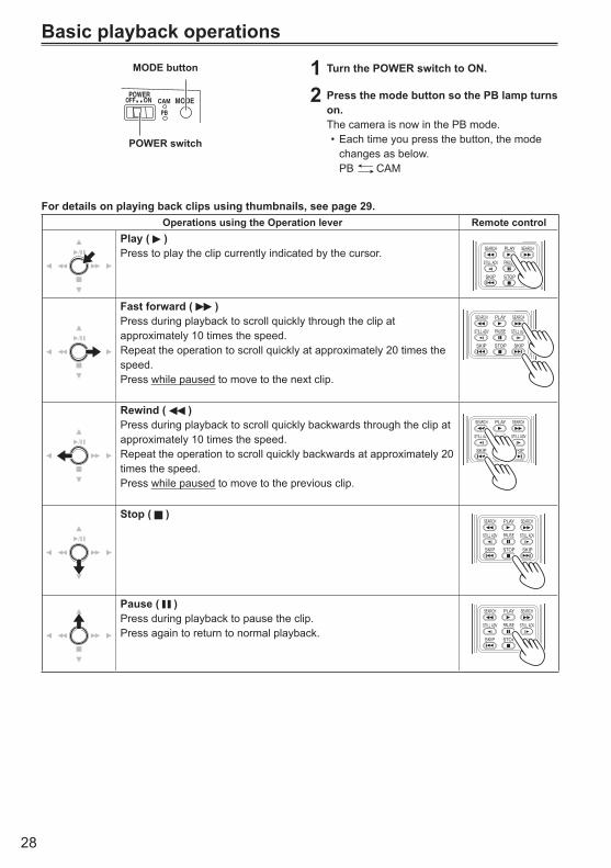
1 Turn the POWER switch to ON.
2 Press the mode button so the PB lamp turns on.The camera is now in the PB mode.
Each time you press the button, the mode •changes as below.
PB CAM
Basic playback operations
For details on playing back clips using thumbnails, see page 29.Operations using the Operation lever Remote control
Play ( )Press to play the clip currently indicated by the cursor.
ZOOM
START/STOPPHOTO
SHOTEXT
DISPLAY
DATE/TIME
VOL
PLAY
STOPSKIP SKIP
MENU
ENTER
PAUSE
SEARCH
STILL ADV STILL ADV
SEARCH
Fast forward ( )Press during playback to scroll quickly through the clip at approximately 10 times the speed. Repeat the operation to scroll quickly at approximately 20 times the speed.Press while paused to move to the next clip.
ZOOM
START/STOPPHOTO
SHOTEXT
DISPLAY
DATE/TIME
VOL
PLAY
STOPSKIP SKIP
MENU
ENTER
PAUSE
SEARCH
STILL ADV STILL ADV
SEARCH
Rewind ( )Press during playback to scroll quickly backwards through the clip at approximately 10 times the speed. Repeat the operation to scroll quickly backwards at approximately 20 times the speed.Press while paused to move to the previous clip.
ZOOM
START/STOPPHOTO
SHOTEXT
DISPLAY
DATE/TIME
VOL
PLAY
STOPSKIP SKIP
MENU
ENTER
PAUSE
SEARCH
STILL ADV STILL ADV
SEARCH
Stop ( )
ZOOM
START/STOPPHOTO
SHOTEXT
DISPLAY
DATE/TIME
VOL
PLAY
STOPSKIP SKIP
MENU
ENTER
PAUSE
SEARCH
STILL ADV STILL ADV
SEARCH
Pause ( )Press during playback to pause the clip.Press again to return to normal playback.
ZOOM
START/STOPPHOTO
SHOTEXT
DISPLAY
DATE/TIME
VOL
PLAY
STOPSKIP SKIP
MENU
ENTER
PAUSE
SEARCH
STILL ADV STILL ADV
SEARCH
MODEPOWER
CAMON..OFF
PB
MODE button
POWER switch
29
Play
back
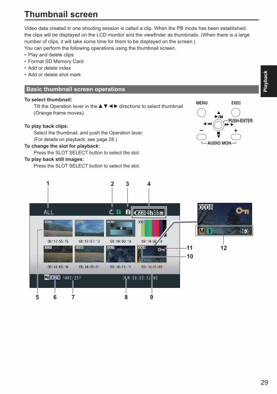
Thumbnail screenVideo data created in one shooting session is called a clip. When the PB mode has been established, the clips will be displayed on the LCD monitor and the viewfinder as thumbnails. (When there is a large number of clips, it will take some time for them to be displayed on the screen.)You can perform the following operations using the thumbnail screen.
Play and delete clips•Format SD Memory Card•Add or delete index•Add or delete shot mark•
Basic thumbnail screen operationsTo select thumbnail: Tilt the Operation lever in the directions to select thumbnail
(Orange frame moves).
To play back clips: Select the thumbnail, and push the Operation lever.
(For details on playback, see page 28.)To change the slot for playback: Press the SLOT SELECT button to select the slot.To play back still images: Press the SLOT SELECT button to select the slot.
MENU
START/STOP 2 PUSH-ENTER
+–
AUDIO MON
EXEC
1012
1 2 3 4
6 7 8 95
11
30
1 Thumbnail display status (Page 34)The types of clips displayed as thumbnails appear in this area.
2 Repeat playback indicator (Page 32)Displayed during repeat playback.
3 Card status displayDisplays status of SD Memory Card.
4 Battery remaining display (Page E-24 of Vol.1)Displays remaining battery capacity.
5 Cursor (Orange frame)Displayed on currently selected thumbnail.
6 Recording mode displayDisplays recording mode if clip currently highlighted by cursor has been recorded in PH mode.
7 Recording format displayDisplays recording format of currently selected clip.
8 Duration displayDisplays duration of currently selected clip.
9 Time display (Page 34)Displays time code at start of clip recording/user information at start of clip recording/time of recording/date of recording/date and time of recording – according to settings.
10 Clip numberDisplayed in order of recording (up to 1000 clips). Numbers of clips that cannot be played back (e.g. clips of different recording formats) are displayed in red. To play clips displayed in red, set the PB format in the settings menu PLAY SETUP screen to the appropriate recording format (Page 64).
11 : Clip protect displayDisplayed on protected clips.
12 IndicatorsM : Shot markThis indicates that a clip has a shot mark. (Next page)I : Index
Displayed when indexes have been attached (Page 35).
: Resume playback displayDisplayed on clips on which resume playback setting has been applied.
Thumbnail screen (continued)
31
Play
back
Adding shot marks to clips
Adding shot marks ( M ) will make it easier to findthe clips you are looking for.
1 Tilt the Operation lever in the directions to move the yellow frame to the clip for which a shot mark is to be added.
2 Press the USER button to which the shot mark function has been allocated. (Page 55)
To release a shot mark, repeat the above steps.It is not possible to add shot marks to clips •recorded using a consumer camcorder model.
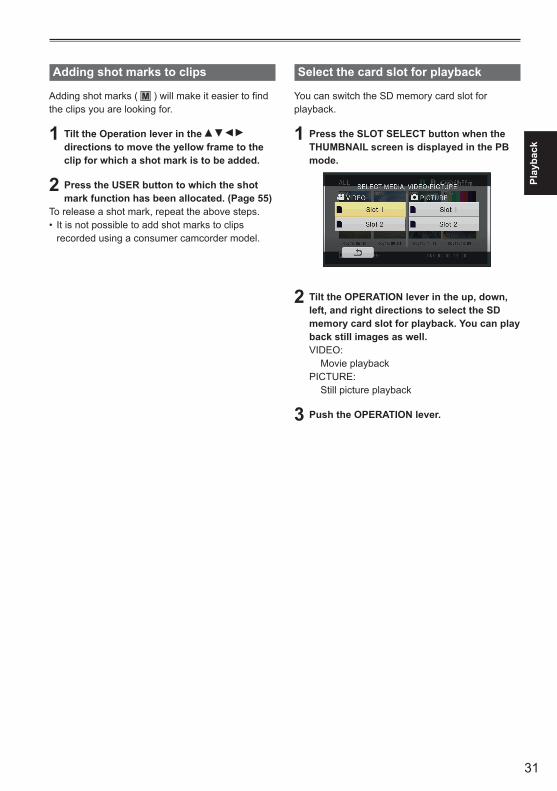
Select the card slot for playback
You can switch the SD memory card slot for playback.
1 Press the SLOT SELECT button when the THUMBNAIL screen is displayed in the PB mode.
2 Tilt the OPERATION lever in the up, down, left, and right directions to select the SD memory card slot for playback. You can play back still images as well.VIDEO: Movie playbackPICTURE: Still picture playback
3 Push the OPERATION lever.
32
Playback settings (PLAY SETUP)Make settings for playback format and method.
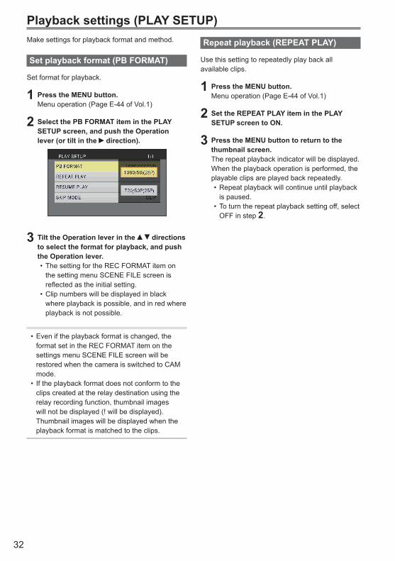
Set playback format (PB FORMAT)
Set format for playback.
1 Press the MENU button.Menu operation (Page E-44 of Vol.1)
2 Select the PB FORMAT item in the PLAY SETUP screen, and push the Operation lever (or tilt in the direction).
3 Tilt the Operation lever in the directions to select the format for playback, and push the Operation lever.
The setting for the REC FORMAT item on •the setting menu SCENE FILE screen is reflected as the initial setting.Clip numbers will be displayed in black •where playback is possible, and in red where playback is not possible.
Even if the playback format is changed, the •format set in the REC FORMAT item on the settings menu SCENE FILE screen will be restored when the camera is switched to CAM mode.If the playback format does not conform to the •clips created at the relay destination using the relay recording function, thumbnail images will not be displayed (! will be displayed). Thumbnail images will be displayed when the playback format is matched to the clips.
Repeat playback (REPEAT PLAY)
Use this setting to repeatedly play back all available clips.
1 Press the MENU button.Menu operation (Page E-44 of Vol.1)
2 Set the REPEAT PLAY item in the PLAY SETUP screen to ON.
3 Press the MENU button to return to the thumbnail screen.The repeat playback indicator will be displayed.When the playback operation is performed, the playable clips are played back repeatedly.
Repeat playback will continue until playback •is paused.To turn the repeat playback setting off, select •OFF in step 2.
33
Play
back
Resume playback (RESUME PLAY)
Use this setting to play back from where clip had previously been paused.
1 Press the MENU button.Menu operation (Page E-44 of Vol.1)
2 Set the RESUME PLAY item in the PLAY SETUP screen to ON.
3 Press the MENU button to return to the thumbnail screen.
4 Select a clip for playback.If playback has previously been paused, the resume playback indicator will be displayed on the clip thumbnail, and the remainder of the clip will be played next time the clip is selected for playback.
To turn the resume playback setting off, •select OFF in step 2.
Set skip method (SKIP MODE)
Select which skip (cue) operation is to be performed when playback is paused.
1 Press the MENU button.Menu operation (Page E-44 of Vol.1)
2 Select the SKIP MODE item in the PLAY SETUP screen.
3 Select skip method.CLIP: Move to the beginning of the previous or next
clip by tilting the Operation lever in the or direction while playback is paused.
CLIP & INDEX: Move to the beginning of the previous or
next clip, or to the previous or next INDEX position, by tilting the Operation lever in the
or direction while playback is paused.
4 Press the MENU button to return to the thumbnail screen.
34
Thumbnail operations
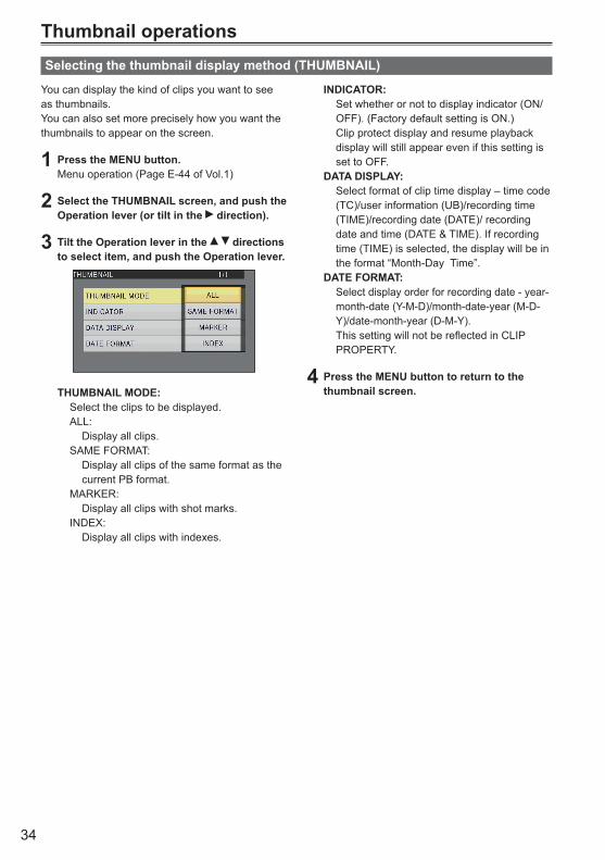
You can display the kind of clips you want to see as thumbnails.You can also set more precisely how you want the thumbnails to appear on the screen.
1 Press the MENU button.Menu operation (Page E-44 of Vol.1)
2 Select the THUMBNAIL screen, and push the Operation lever (or tilt in the direction).
3 Tilt the Operation lever in the directions to select item, and push the Operation lever.
THUMBNAIL MODE: Select the clips to be displayed. ALL: Display all clips. SAME FORMAT: Display all clips of the same format as the
current PB format. MARKER: Display all clips with shot marks. INDEX: Display all clips with indexes.
Selecting the thumbnail display method (THUMBNAIL)
INDICATOR: Set whether or not to display indicator (ON/
OFF). (Factory default setting is ON.) Clip protect display and resume playback display will still appear even if this setting is set to OFF.
DATA DISPLAY: Select format of clip time display – time code
(TC)/user information (UB)/recording time (TIME)/recording date (DATE)/ recording date and time (DATE & TIME). If recording time (TIME) is selected, the display will be in theformat“Month-DayTime”.
DATE FORMAT: Select display order for recording date - year-
month-date (Y-M-D)/month-date-year (M-D-Y)/date-month-year (D-M-Y).
This setting will not be reflected in CLIP PROPERTY.
4 Press the MENU button to return to the thumbnail screen.
35
Play
back
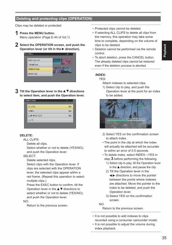
Clips may be deleted or protected.
1 Press the MENU button.Menu operation (Page E-44 of Vol.1)
2 Select the OPERATION screen, and push the Operation lever (or tilt in the direction).
3 Tilt the Operation lever in the directions to select item, and push the Operation lever.
DELETE: ALL CLIPS: Delete all clips.
Select whether or not to delete (YES/NO), and push the Operation lever.
SELECT: Delete selected clips.
Select clips with the Operation lever. If clips are selected with the OPERATION lever, the selected clips appear within a red frame. (Repeat this operation to select multiple clips.)
Press the EXEC button to confirm, tilt the Operation lever in the directions to select whether or not to delete (YES/NO), and push the Operation lever.
NO: Return to the previous screen.
Deleting and protecting clips (OPERATION)
Protected clips cannot be deleted.•If selecting ALL CLIPS to delete all clips from •the memory, this operation may take some time to complete, depending on the volume of clips to be deleted.Deletion cannot be performed via the remote •control.To abort deletion, press the CANCEL button. •The already deleted clips cannot be restored even if the deletion process is aborted.
INDEX: YES: Attach indexes to selected clips. 1) Select clip to play, and push the
Operation lever at the point for an index to be added.
2) Select YES on the confirmation screen to attach index.
•Thepointintheclipatwhichtheindexwill actually be attached will be accurate to within an error of 0.5 seconds.
•Todeleteindex,selectINDEX→YESinstep 3 before performing the following.
1) Select clip to play, tilt the Operation lever in the direction, and pause the clip.
2) Tilt the Operation lever in the directions to move the pointer
between the points where indexes are attached. Move the pointer to the index to be deleted, and push the Operation lever.
3) Select YES on the confirmation screen.
NO: Return to the previous screen.
It is not possible to add indexes to clips •recorded using a consumer camcorder model.It is not possible to adjust the volume during •index playback.
36
Thumbnail operations (continued)
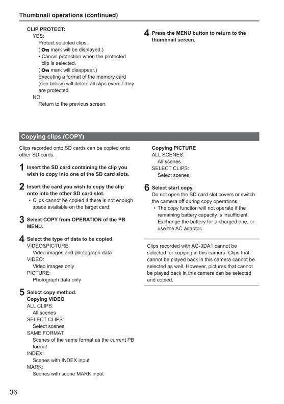
Clips recorded onto SD cards can be copied onto other SD cards.
1 Insert the SD card containing the clip you wish to copy into one of the SD card slots.
2 Insert the card you wish to copy the clip onto into the other SD card slot.
Clips cannot be copied if there is not enough •space available on the target card.
3 Select COPY from OPERATION of the PB MENU.
4 Select the type of data to be copied.VIDEO&PICTURE: Video images and photograph dataVIDEO: Video images onlyPICTURE: Photograph data only
5 Select copy method.Copying VIDEOALL CLIPS: All scenesSELECT CLIPS: Select scenes.SAME FORMAT: Scenes of the same format as the current PB
formatINDEX: Scenes with INDEX inputMARK: Scenes with scene MARK input
Copying clips (COPY)
Copying PICTUREALL SCENES: All scenesSELECT CLIPS: Select scenes.
6 Select start copy.Do not open the SD card slot covers or switch the camera off during copy operations.
The copy function will not operate if the •remaining battery capacity is insufficient. Exchange the battery for a charged one, or use the AC adaptor.
Clips recorded with AG-3DA1 cannot be selected for copying in this camera. Clips that cannot be played back in this camera cannot be selected as well. However, pictures that cannot be played back in this camera can be selected and copied.
CLIP PROTECT: YES: Protect selected clips. ( mark will be displayed.) •Cancelprotectionwhentheprotected
clip is selected. ( mark will disappear.) Executing a format of the memory card
(see below) will delete all clips even if they are protected.
NO: Return to the previous screen.
4 Press the MENU button to return to the thumbnail screen.

37
Play
back
SD Memory Cards can be formatted, and clip and SD Memory Card information can be checked.
1 Press the MENU button.Menu operation (Page E-44 of Vol.1)
2 Select CARD FUNCTIONS, and push the Operation lever (or tilt in the direction).
Format card and check clip and card information (CARD FUNCTIONS)
3 Tilt the Operation lever in the directions to select item, and push the Operation lever.
CARD FORMAT:Insert card to be formatted into the camera.•SD Memory Card will be formatted.•
Proceeding will delete the entire data, including videos and picture data, from the card.
Select whether or not to format (YES/NO), and push the Operation lever.
CARD STATUS: Display SD Memory Card information.
(Next page)CLIP PROPERTY: Display information of selected clip.
(Next page)Tilt the Operation lever in the • directions to display information from previous or subsequent clips.
4 Press the MENU button to return to the thumbnail screen.
38
Thumbnail operations (continued)
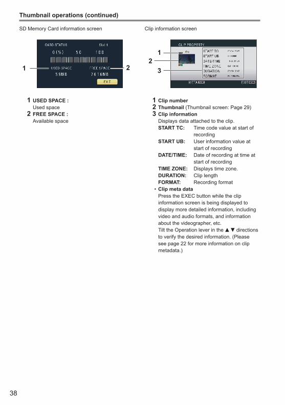
SD Memory Card information screen
1 2
1 USED SPACE : Used space2 FREE SPACE : Available space
Clip information screen
12
3
1 Clip number2 Thumbnail (Thumbnail screen: Page 29)3 Clip information Displays data attached to the clip. START TC: Time code value at start of
recording START UB: User information value at
start of recording DATE/TIME: Date of recording at time at
start of recording TIME ZONE: Displays time zone. DURATION: Clip length FORMAT: Recording format
Clip meta data• Press the EXEC button while the clip
information screen is being displayed to display more detailed information, including video and audio formats, and information about the videographer, etc. Tilt the Operation lever in the directions to verify the desired information. (Please see page 22 for more information on clip metadata.)
39
Play
back
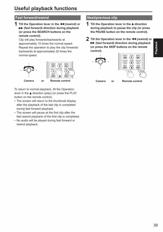
Useful playback functionsFast forward/rewind
1 Tilt the Operation lever in the (rewind) or (fast forward) direction during playback
(or press the SEARCH buttons on the remote control).Clip will play forwards/backwards at approximately 10 times the normal speed. Repeat the operation to play the clip forwards/backwards at approximately 20 times the normal speed.
ZOOM
START/STOPPHOTO
SHOTEXT
DISPLAY
DATE/TIME
VOL
PLAY
STOPSKIP SKIP
MENU
ENTER
PAUSE
SEARCH
STILL ADV STILL ADV
SEARCH
Camera or Remote control
To return to normal playback, tilt the Operation lever in the direction (play) (or press the PLAY button on the remote control).
The screen will return to the thumbnail display •after the playback of the last clip is completed during fast forward playback.The screen will pause at the first clip after the •fast rewind playback of the first clip is completed.No audio will be played during fast forward or •rewind playback.
Next/previous clip
1 Tilt the Operation lever in the direction during playback to pause the clip (or press the PAUSE button on the remote control).
2 Tilt the Operation lever in the (rewind) or (fast forward) direction during playback
(or press the SKIP buttons on the remote control).
Camera or Remote control
ZOOM
START/STOPPHOTO
SHOTEXT
DISPLAY
DATE/TIME
VOL
PLAY
STOPSKIP SKIP
MENU
ENTER
PAUSE
SEARCH
STILL ADV STILL ADV
SEARCH
40
Useful playback functions (continued)
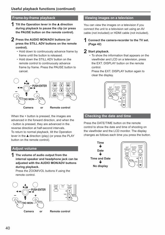
Frame-by-frame playback
1 Tilt the Operation lever in the direction during playback to pause the clip (or press the PAUSE button on the remote control).
2 Press the AUDIO MON/ADV buttons (or press the STILL ADV buttons on the remote control).
Hold down to continuously advance frame by •frame until the button is released.Hold down the STILL ADV button on the •remote control to continuously advance frame by frame. Press the PAUSE button to cancel.
Camera or Remote control
ZOOM
START/STOPPHOTO
SHOTEXT
DISPLAY
DATE/TIME
VOL
PLAY
STOPSKIP SKIP
MENU
ENTER
PAUSE
SEARCH
STILL ADV STILL ADV
SEARCH
MENU
START/STOP 2 PUSH-ENTER
+–
AUDIO MON
EXEC
When the + button is pressed, the images are advanced in the forward direction, and when the - button is pressed, they are advanced in the reverse direction at half-second intervals.To return to normal playback, tilt the Operation lever in the direction (play) (or press the PLAY button on the remote control).
Adjust volume
1 The volume of audio output from the internal speaker and headphone jack can be adjusted with the AUDIO MON/ADV buttons during playback.Press the ZOOM/VOL buttons if using the remote control.
Camera or Remote control
ZOOM
START/STOPPHOTO
SHOTEXT
DISPLAY
DATE/TIME
VOL
PLAY
STOPSKIP SKIP
MENU
ENTER
PAUSE
SEARCH
STILL ADV STILL ADV
SEARCH
MENU
START/STOP 2 PUSH-ENTER
+–
AUDIO MON
EXEC
Viewing images on a television
You can view the images on a television if you connect the unit to a television set using an AV cable (not included) or HDMI cable (not included).
1 Connect the camera-recorder to the TV set. (Page 42)
2 Start playback.To show the information that appears on the •viewfinder and LCD on a television, press the EXT. DISPLAY button on the remote control. Press the EXT. DISPLAY button again to clear the display.
ZOOM
START/STOPPHOTO
SHOTEXT
DISPLAY
DATE/TIME
VOL
PLAY
STOPSKIP SKIP
MENU
ENTER
PAUSE
SEARCH
STILL ADV STILL ADV
SEARCH
Checking the date and time
Press the DATE/TIME button on the remote control to show the date and time of shooting on the viewfinder and the LCD monitor. The display changes as follows each time you press the button.
Time
Date
Time and Date
No display
ZOOM
START/STOPPHOTO
SHOTEXT
DISPLAY
DATE/TIME
VOL
PLAY
STOPSKIP SKIP
MENU
ENTER
PAUSE
SEARCH
STILL ADV STILL ADV
SEARCH
41
Editi
ng
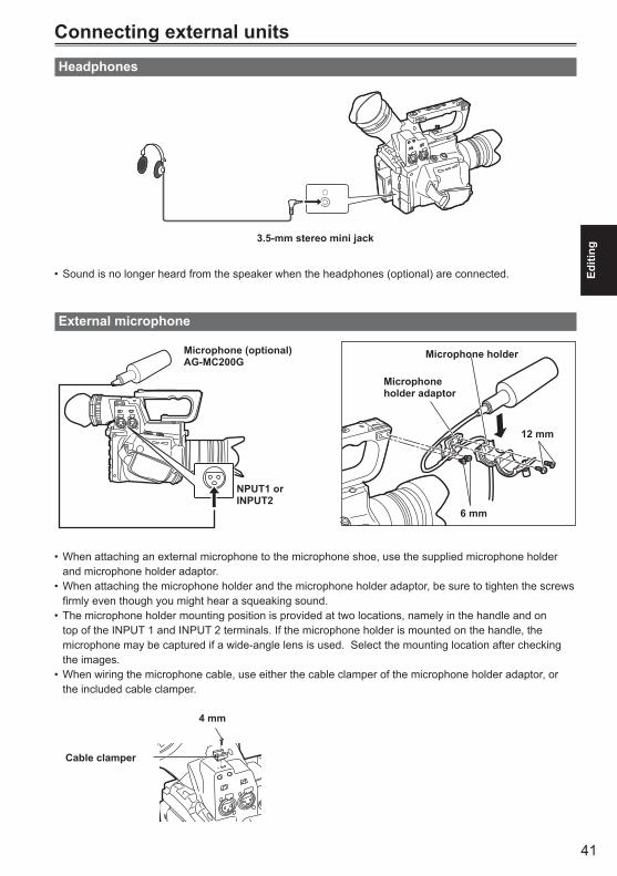
Connecting external unitsHeadphones
3.5-mm stereo mini jack
Sound is no longer heard from the speaker when the headphones (optional) are connected.•
External microphone
Microphone (optional)AG-MC200G
NPUT1 orINPUT2
Microphone holder
Microphone holder adaptor
6 mm
12 mm
When attaching an external microphone to the microphone shoe, use the supplied microphone holder •and microphone holder adaptor.When attaching the microphone holder and the microphone holder adaptor, be sure to tighten the screws •firmly even though you might hear a squeaking sound.The microphone holder mounting position is provided at two locations, namely in the handle and on •top of the INPUT 1 and INPUT 2 terminals. If the microphone holder is mounted on the handle, the microphone may be captured if a wide-angle lens is used. Select the mounting location after checking the images. When wiring the microphone cable, use either the cable clamper of the microphone holder adaptor, or •the included cable clamper.
Cable clamper
4 mm
42
Connecting external units (continued)
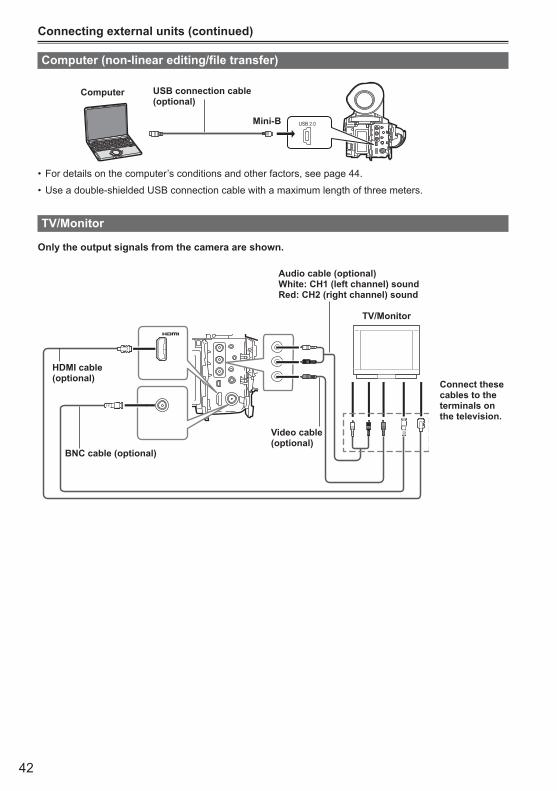
Computer (non-linear editing/file transfer)
USB 2.0
Computer USB connection cable (optional)
Mini-B
For details on the computer’s conditions and other factors, see page 44.•
Use a double-shielded USB connection cable with a maximum length of three meters. •
TV/Monitor
Only the output signals from the camera are shown.
HDMI cable(optional)
BNC cable (optional)
Video cable(optional)
Audio cable (optional)White: CH1 (left channel) soundRed: CH2 (right channel) sound
Connect these cables to the terminals on the television.
TV/Monitor
43
Editi
ng
When outputting video and audio signals from the camera to an external device, connect to the ■input terminals of the external device.
Use a double-shielded HDMI cable (not included). •It is recommended that you use Panasonic’s HDMI cable.•This product is not compatible with VIERA Link.•
Limitations of image output ■When using SDIOUT output, side LCD and EVF cannot be operated simultaneously. In order to perform •simultaneous operation, set the SDI OUT on the settings menu AV IN/OUT SETUP to OFF. When the EVF MODE on the settings menu DISPLAY SETUP is set to AUTO, EVF disappears upon opening/closing of the LCD.No HDMI output is performed when REC FORMAT is set to 1080/24p and SDI 24Ps is set to ON. •When SDI&HDMI OUT SEL is set to DOWNCONV, SIDE CROP is disabled in the DOWNCON MODE •settings, and SQUEEZE is enabled automatically.Some displays, such as time code display and audio level meter display may not be visible on the videos •output from the VIDEO OUT terminal.
44
Nonlinear editingNon-linear editing of video data on SD Memory Cards can be performed by connecting the camera via the USB connection cable to a computer for editing. (As for connection, refer to page 42)Use a sufficiently charged battery or the AC adaptor.
The following conditions are necessary for USB connection.
PC with Windows XP, Windows Vista, or •Windows 7; or Macintosh with Intel CPU (Intel Mac)USB 2.0 (High Speed, Mass Storage Class) •compatibility (not compatible with USB 1.1)Only connect to one computer at a time.•Camera cannot be operated if a hub or other •device is connected between the camera and computer.
1 Insert the SD Memory Card, and move the POWER switch to ON.
2 Connect the camera to the computer with the USB connection cable.Turn the computer’s power on before connecting.
3 Select ‘PC’Dubbing can be performed to a Blu-ray Disc Recorder, etc. by selecting ‘RECORDER’.
4 Perform non-linear editing on the computer.The contents of the SD Memory Card will appear as a removable disk icon within My Computer or the desktop on the computer screen. (Page 73)(Example) Windows
Removable disk (E:)
(Example) Macintosh
NO NAME
When copying files from the camera to a •computer, be careful to ensure that files are not accidentally overwritten.For more details, please refer to your •computer editing software’s operating instructions.When changing cards, always ensure that •the access lamp is not flashing and that the card is not currently being accessed.Camera functions cannot be used when the •camera is connected to a computer.Alwaysperform“safehardwareremoval”•when disconnecting the cable.The data on the SD Memory Card cannot be •accessed when the SD Memory Card slot cover is open.
5 Turn the camera’s power off.
If the camera cannot be correctly recognized •by the computer, this may be able to be remedied by one of the following methods.
Turn the power of the camera and the ācomputer off and back on again.Remove the SD Memory Card from the ācamera and reinsert it.Connect to a different USB terminal on the ācomputer.
If you are using an SDXC memory card, •some personal computers may not recognize the data. Make sure your personal computer supports SDXC cards.
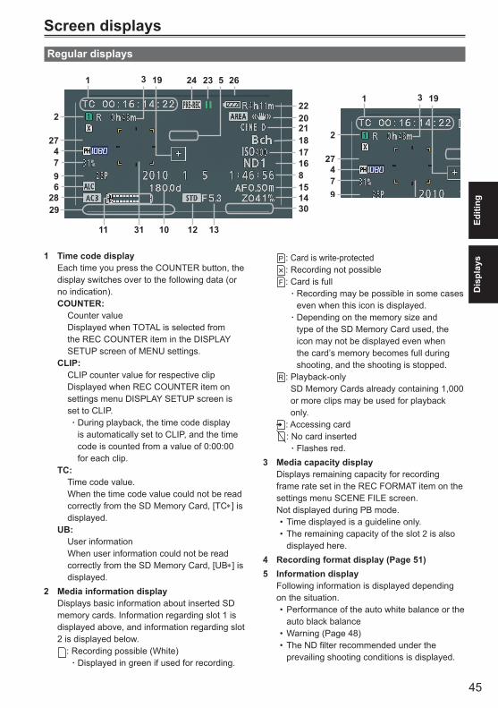
45
Dis
play
sEd
iting
Screen displaysRegular displays
1
2
274796
28
11 10 12 13
141581617
24 23193 5
18212022
29 30
31
26
1
2
274796
28
11 10 12 13
141581617
24 23193 5
18212022
29 30
31
26
1 Time code displayEach time you press the COUNTER button, the display switches over to the following data (or no indication).COUNTER: Counter value Displayed when TOTAL is selected from
the REC COUNTER item in the DISPLAY SETUP screen of MENU settings.
CLIP: CLIP counter value for respective clip Displayed when REC COUNTER item on
settings menu DISPLAY SETUP screen is set to CLIP.
During playback, the time code display āis automatically set to CLIP, and the time code is counted from a value of 0:00:00 for each clip.
TC: Time code value. When the time code value could not be read
correctly from the SD Memory Card, [TC∗] is displayed.
UB: User information When user information could not be read
correctly from the SD Memory Card, [UB∗] is displayed.
2 Media information displayDisplays basic information about inserted SD memory cards. Information regarding slot 1 is displayed above, and information regarding slot 2 is displayed below.
: Recording possible (White)Displayed in green if used for recording. ā
: Card is write-protected: Recording not possible: Card is full
Recording may be possible in some cases āeven when this icon is displayed.Depending on the memory size and ātype of the SD Memory Card used, the icon may not be displayed even when the card’s memory becomes full during shooting, and the shooting is stopped.
: Playback-only SD Memory Cards already containing 1,000 or more clips may be used for playback only.
: Accessing card: No card inserted
Flashes red. ā3 Media capacity display
Displays remaining capacity for recording frame rate set in the REC FORMAT item on the settings menu SCENE FILE screen.Not displayed during PB mode.
Time displayed is a guideline only.•The remaining capacity of the slot 2 is also •displayed here.
4 Recording format display (Page 51)5 Information display
Following information is displayed depending on the situation.
Performance of the auto white balance or the •auto black balanceWarning (Page 48)•The ND filter recommended under the •prevailing shooting conditions is displayed.

46
Screen displays (continued)
(Continued on the next page)
The AWB error message (LOW LIGHT / •LEVEL OVER) is displayed. (Page E-42 of Vol.1)The functions allocated to the USER buttons •are displayed while you hold down the DISP/ MODE CHK button.
6 Microphone level automatic control displayAppears when in the setup menus, RECORDING SETUP screen, MIC ALC, you haveselected“ON”.
7 Marker luminance displayWhen markers are displayed, the brightness level around the center of the screen is indicatedas0%to99%.“99%↑”appearsifthepercentage is over 99.
When the AREA Y-GET function is operating, •the brightness level around the center of the AREA frame is displayed.
8 Date and time displayMonth
mmm dd yyyy hh:mm:ss
Day of the month
Year:2001 - 2039Hours
Minutes
Seconds
9 Frame rate displayDisplays recording frame rate.Not displayed when set to 1080/60i.
10 Shutter speed displayThe shutter speed is displayed here.
11 Audio level meter display (Page 18)12 Auto iris control display
STD: Standard auto-iris controlSPOT: Auto iris control for spotlightBACK: Auto iris control for backlight
compensation13 Iris display
Displays F value. The STEP of the display value differs depending on the lens.
14 Zoom position displayThe zoom poison is displayed with Z00 (maximum wide-angle) - Z99 (maximum zoom).The unit can be switched to mm in the ZOOM & FOCUS item of the setting menu DISPLAY SETUP screen.The focus position display does not move linearly.
15 Focus control information displayDisplays the focus control information with 99 - 00.In the auto focus mode, AF appears. In the manual focus mode, MF appears. The units can be switched between feet and m in the ZOOM & FOCUS item of the setting menu DISPLAY SETUP screen.The STEP of the display value differs depending on the lens.
16 ND filter displayND filter selected is displayed.
17 Gain displayDisplays the gain value of the image amplifier configured. (During the auto mode, AGC is displayed.)
18 AWB information displayDisplays the information of white balance.ATW: When ATW is setP3.2K/P5.6K/VAR: In the case of presetAch/Bch: In the case of A/BLOCK: When ATW is locked
19 Marker displayDuring shooting, pressing the ZEBRA button once or twice will display the marker.
20 Optical Image Stabilizer displayDisplayed when Optical Image Stabilizer is ON.
21 Scene filename display (Page 19)22 Remaining battery capacity display
When using Panasonic-manufactured batteries compatible with this product, the remaining battery capacity is displayed in minutes.Time remaining will be displayed after a brief pause.
The battery display will change •→ → → →
as battery capacity decreases. will be displayed in red when less than 3 minutes are remaining, and will flash when the battery is empty.
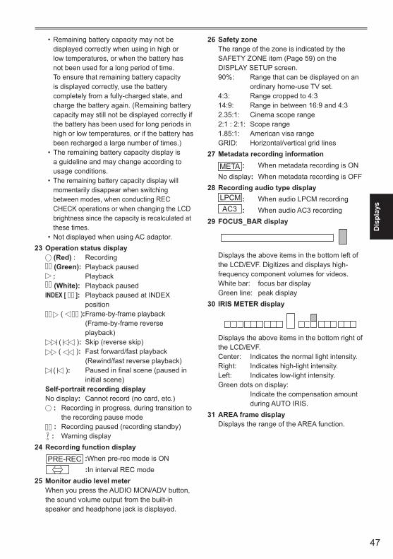
47
Dis
play
s
Remaining battery capacity may not be •displayed correctly when using in high or low temperatures, or when the battery has not been used for a long period of time. To ensure that remaining battery capacity is displayed correctly, use the battery completely from a fully-charged state, and charge the battery again. (Remaining battery capacity may still not be displayed correctly if the battery has been used for long periods in high or low temperatures, or if the battery has been recharged a large number of times.)The remaining battery capacity display is •a guideline and may change according to usage conditions.The remaining battery capacity display will •momentarily disappear when switching between modes, when conducting REC CHECK operations or when changing the LCD brightness since the capacity is recalculated at these times.Not displayed when using AC adaptor.•
23 Operation status display (Red) : Recording (Green): Playback paused : Playback (White): Playback paused
INDEX [ ]: Playback paused at INDEX position
( ): Frame-by-frame playback (Frame-by-frame reverse playback)
( ): Skip (reverse skip) ( ): Fast forward/fast playback
(Rewind/fast reverse playback) ( ): Paused in final scene (paused in
initial scene)Self-portrait recording displayNo display: Cannot record (no card, etc.)
: Recording in progress, during transition to the recording pause mode
: Recording paused (recording standby) : Warning display
24 Recording function displayPRE-REC :When pre-rec mode is ON
:In interval REC mode25 Monitor audio level meter
When you press the AUDIO MON/ADV button, the sound volume output from the built-in speaker and headphone jack is displayed.
26 Safety zoneThe range of the zone is indicated by the SAFETY ZONE item (Page 59) on the DISPLAY SETUP screen.90%: Range that can be displayed on an
ordinary home-use TV set.4:3: Range cropped to 4:314:9: Range in between 16:9 and 4:32.35:1: Cinema scope range2:1 : 2:1: Scope range1.85:1: American visa rangeGRID: Horizontal/vertical grid lines
27 Metadata recording information
META : When metadata recording is ONNo display: When metadata recording is OFF
28 Recording audio type displayLPCM : When audio LPCM recordingAC3 : When audio AC3 recording
29 FOCUS_BAR display
Displays the above items in the bottom left of the LCD/EVF. Digitizes and displays high-frequency component volumes for videos. White bar: focus bar displayGreen line: peak display
30 IRIS METER display
Displays the above items in the bottom right of the LCD/EVF. Center: Indicates the normal light intensity.Right: Indicates high-light intensity.Left: Indicates low-light intensity.Green dots on display: Indicate the compensation amount
during AUTO IRIS.31 AREA frame display
Displays the range of the AREA function.
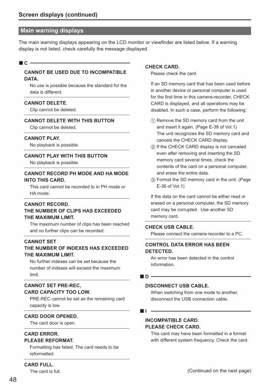
48
Screen displays (continued)
(Continued on the next page)
C ■CANNOT BE USED DUE TO INCOMPATIBLE DATA. No use is possible because the standard for the
data is different.
CANNOT DELETE. Clip cannot be deleted.
CANNOT DELETE WITH THIS BUTTON Clip cannot be deleted.
CANNOT PLAY. No playback is possible.
CANNOT PLAY WITH THIS BUTTON No playback is possible.
CANNOT RECORD PH MODE AND HA MODE INTO THIS CARD. This card cannot be recorded to in PH mode or
HA mode.
CANNOT RECORD.THE NUMBER OF CLIPS HAS EXCEEDED THE MAXIMUM LIMIT. The maximum number of clips has been reached
and no further clips can be recorded.
CANNOT SET THE NUMBER OF INDEXES HAS EXCEEDED THE MAXIMUM LIMIT. No further indexes can be set because the
number of indexes will exceed the maximum limit.
CANNOT SET PRE-REC, CARD CAPACITY TOO LOW. PRE-REC cannot be set as the remaining card
capacity is low.
CARD DOOR OPENED. The card door is open.
CARD ERROR.PLEASE REFORMAT. Formatting has failed. The card needs to be
reformatted.
CARD FULL. The card is full.
CHECK CARD. Please check the card.
If an SD memory card that has been used before in another device or personal computer is used for the first time in this camera-recorder, CHECK CARD is displayed, and all operations may be disabled. In such a case, perform the following:
1 Remove the SD memory card from the unit and insert it again. (Page E-38 of Vol.1) The unit recognizes the SD memory card and cancels the CHECK CARD display.
2 If the CHECK CARD display is not canceled even after removing and inserting the SD memory card several times, check the contents of the card on a personal computer, and erase the entire data.
3 Format the SD memory card in the unit. (Page E-36 of Vol.1)
If the data on the card cannot be either read or erased on a personal computer, the SD memory card may be corrupted. Use another SD memory card.
CHECK USB CABLE. Please connect the camera-recorder to a PC.
CONTROL DATA ERROR HAS BEEN DETECTED. An error has been detected in the control
information.
D ■DISCONNECT USB CABLE. When switching from one mode to another,
disconnect the USB connection cable.
I ■INCOMPATIBLE CARD.PLEASE CHECK CARD. This card may have been formatted in a format
with different system frequency. Check the card.
Main warning displays
The main warning displays appearing on the LCD monitor or viewfinder are listed below. If a warning display is not listed, check carefully the message displayed.
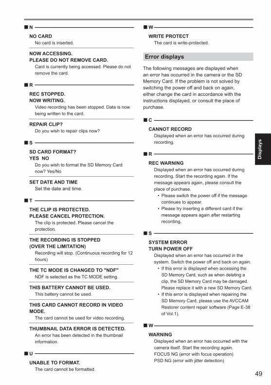
49
Dis
play
s
N ■NO CARD No card is inserted.
NOW ACCESSING.PLEASE DO NOT REMOVE CARD. Card is currently being accessed. Please do not
remove the card.
R ■REC STOPPED.NOW WRITING. Video recording has been stopped. Data is now
being written to the card.
REPAIR CLIP? Do you wish to repair clips now?
S ■SD CARD FORMAT?YES NO Do you wish to format the SD Memory Card
now? Yes/No
SET DATE AND TIME Set the date and time.
T ■THE CLIP IS PROTECTED. PLEASE CANCEL PROTECTION. The clip is protected. Please cancel the
protection.
THE RECORDING IS STOPPED(OVER THE LIMITATION) Recording will stop. (Continuous recording for 12
hours)
THE TC MODE IS CHANGED TO "NDF" NDF is selected as the TC MODE setting.
THIS BATTERY CANNOT BE USED. This battery cannot be used.
THIS CARD CANNOT RECORD IN VIDEO MODE. The card cannot be used for video recording.
THUMBNAIL DATA ERROR IS DETECTED. An error has been detected in the thumbnail
information.
U ■UNABLE TO FORMAT. The card cannot be formatted.
W ■WRITE PROTECT The card is write-protected.
Error displays
The following messages are displayed when an error has occurred in the camera or the SD Memory Card. If the problem is not solved by switching the power off and back on again, either change the card in accordance with the instructions displayed, or consult the place of purchase.
C ■CANNOT RECORD Displayed when an error has occurred during
recording.
R ■REC WARNING Displayed when an error has occurred during
recording. Start the recording again. If the message appears again, please consult the place of purchase.
Please switch the power off if the message •continues to appear.Please try inserting a different card if the •message appears again after restarting recording.
S ■SYSTEM ERROR TURN POWER OFF Displayed when an error has occurred in the
system. Switch the power off and back on again.If this error is displayed when accessing the •SD Memory Card, such as when deleting a clip, the SD Memory Card may be damaged. Please replace it with a new SD Memory Card.If this error is displayed when repairing the •SD Memory Card, please use the AVCCAM Restorer content repair software (Page E-38 of Vol.1).
W ■WARNING Displayed when an error has occurred with the
camera itself. Start the recording again. FOCUS NG (error with focus operation) PSD NG (error with jitter detection)
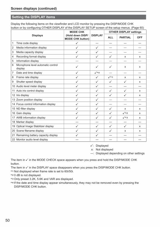
50
Screen displays (continued)
Setting the DISPLAY items
Display the following items on the viewfinder and LCD monitor by pressing the DISP/MODE CHKbutton or by configuring OTHER DISPLAY of the DISPLAY SETUP screen of the setup menus. (Page 60)
DisplaysMODE CHK
(Hold down DISP/MODE CHK button)
DISPLAYOTHER DISPLAY settings
ALL PARTIAL OFF
1 Time code display — — — —
2 Media information display — — —
3 Media capacity display — — —
4 Recording format display x x5 Information display — — — — —6 Microphone level automatic control
display x x
7 Date and time display ∗4 — — —
8 Frame rate display ∗1 x x
9 Shutter speed display x
10 Audio level meter display — — —
11 Auto iris control display x
12 Iris display x
13 Zoom position display — — —
14 Focus control information display — — —
15 ND filter display x x
16 Gain display ∗2 x
17 AWB information display ∗3 x18 Marker display — — — — —19 Optical Image Stabilizer display x
20 Scene filename display x x
21 Remaining battery capacity display — — —22 Monitor audio level display — — — — —
: Displayed x: Not displayed—: Displayed depending on other settings
The item in in the MODE CHECK space appears when you press and hold the DISP/MODE CHK button.The item in in the DISPLAY space disappears when you press the DISP/MODE CHK button.∗1 Not displayed when frame rate is set to 60i/50i.∗2 0 dB is not displayed.∗3 Only preset 3.2K, 5.6K and VAR are displayed.∗4 If the date and time display appear simultaneously, they may not be removed even by pressing the
DISP/MODE CHK button.
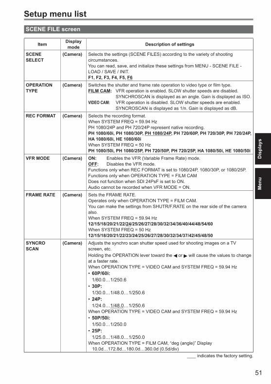
51
Dis
play
sM
enu
Setup menu listSCENE FILE screen
Item Display mode Description of settings
SCENE SELECT
(Camera) Selects the settings (SCENE FILES) according to the variety of shooting circumstances. You can read, save, and initialize these settings from MENU - SCENE FILE - LOAD / SAVE / INIT. F1, F2, F3, F4, F5, F6
OPERATION TYPE
(Camera) Switches the shutter and frame rate operation to video type or film type.FILM CAM: VFR operation is enabled. SLOW shutter speeds are disabled.
SYNCHROSCAN is displayed as an angle. Gain is displayed as ISO. VIDEO CAM: VFR operation is disabled. SLOW shutter speeds are enabled.
SYNCROSCAN is displayed as 1/n. Gain is displayed as dB.
REC FORMAT (Camera) Selects the recording format.When SYSTEM FREQ = 59.94 HzPH 1080/24P and PH 720/24P represent native recording.PH 1080/60i, PH 1080/30P, PH 1080/24P, PH 720/60P, PH 720/30P, PH 720/24P, HA 1080/60i, HE 1080/60iWhen SYSTEM FREQ = 50 HzPH 1080/50i, PH 1080/25P, PH 720/50P, PH 720/25P, HA 1080/50i, HE 1080/50i
VFR MODE (Camera) ON: Enables the VFR (Variable Frame Rate) mode.OFF: Disables the VFR mode.Functions only when REC FORMAT is set to 1080/24P, 1080/30P, or 1080/25P.Functions only when OPERATION TYPE = FILM CAMDoes not function when SDI 24PsF is set to ON.Audio cannot be recorded when VFR MODE = ON.
FRAME RATE (Camera) Sets the FRAME RATE.Operates only when OPERATION TYPE = FILM CAM.You can make the settings from SHUTR/F.RATE on the rear side of the camera also. When SYSTEM FREQ = 59.94 Hz12/15/18/20/21/22/24/25/26/27/28/30/32/34/36/40/44/48/54/60When SYSTEM FREQ = 50 Hz12/15/18/20/21/22/23/24/25/26/27/28/30/32/34/37/42/45/48/50
SYNCRO SCAN
(Camera) Adjusts the synchro scan shutter speed used for shooting images on a TV screen, etc. Holding the OPERATION lever toward the or will cause the values to change at a faster rate. When OPERATION TYPE = VIDEO CAM and SYSTEM FREQ = 59.94 Hz
60P/60i: •1/60.0…1/250.6 30P: •1/30.0…1/48.0…1/250.6 24P: •1/24.0…1/48.0…1/250.6
When OPERATION TYPE = VIDEO CAM and SYSTEM FREQ = 59.94 Hz50P/50i: •1/50.0…1/250.025P: •1/25.0…1/48.0…1/250.0
WhenOPERATIONTYPE=FILMCAM,“deg(angle)”Display 10.0d…172.8d…180.0d…360.0d (0.5d/div)
indicates the factory setting.

52
Setup menu list (continued)
SCENE FILE screen (continued)
Item Display mode Description of settings
DETAIL LEVEL (Camera) Adjusts the level of the image outline correction (in the horizontal and vertical directions). -7…0…+7
V DETAIL LEVEL
(Camera) Adjusts the level of outline correction in the vertical direction. -7…0…+7
DETAIL CORING
(Camera) Adjusts the level of noise reduction of the detail signal. Set to – for a clearer image. Noise increases slightly. Set to + to reduce noise. -7…0…+7
CHROMA LEVEL
(Camera) Adjusts the chroma level.-7…0…+7
CHROMA PHASE
(Camera) Adjusts the chroma level. -7…0…+7
COLOR TEMP Ach
(Camera) Make fine adjustments to the color temperature (after white balance Ach adjustment).-7…0…+7
COLOR TEMP Bch
(Camera) Make fine adjustments to the color temperature (after white balance Bch adjustment). -7…0…+7
MASTER PED (Camera) Adjusts the master pedestal (black level of the image) as the basis for images. -15…0…+15
A.IRIS LEVEL (Camera) Sets the desired AUTO IRIS level.-6…0…+6
DRS (Camera) Selects the DRS (Dynamic Range Stretcher) function. It enables the dynamic range to be expanded by compressing the level of the video signals in the high-brightness areas where overexposure results during normal shooting.OFF, 1, 2, 3
The higher the number of the setting, the higher the compression level of the •high-brightness areas. The higher the number of the setting, the greater the interference in darker areas.•
GAMMA (Camera) Selects the gamma curves. HD NORM: This gamma setting is suitable for HD shooting. LOW: Makes a mellow image using the gamma curve that has a gentle
incline in low-brightness curve. The contrast sharpens.SD NORM: This is the normal video setting carried over from the DVX100 series.HIGH: Expands the tone of dark parts and makes a brighter image using the
gamma curve that has a sharp incline in low-brightness curve. The contrast softens.
B.PRESS: Makes the contrast sharper than LOW. CINE-LIKE D: Uses a gamma curve designed to create cinema-like images. CINE-LIKE V: Uses a gamma curve designed to create cinema-like images with
emphasized contrast.When you select CINE-LIKE gamma, we recommend setting the lens aperture •lower than normal image level (approximately 1/2) for optimal results.
KNEE (Camera) To avoid overexposure, select the compression level (knee point) of the high intensity video signals received through the image pickup device. AUTO: Sets the level automatically according to the received signals.LOW: Low setting (Compression starts at approx. 80%)MID: Medium setting (Compression starts at approx. 90%)HIGH: High setting (Compression starts at approx. 100%)
Not available when a DRS value is set, or when GAMMA is set to CINE-LIKE. • indicates the factory setting.
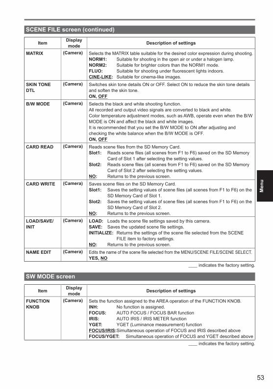
53
Men
u
Item Display mode Description of settings
MATRIX (Camera) Selects the MATRIX table suitable for the desired color expression during shooting.NORM1: Suitable for shooting in the open air or under a halogen lamp.NORM2: Suitable for brighter colors than the NORM1 mode.FLUO: Suitable for shooting under fluorescent lights indoors.CINE-LIKE: Suitable for cinema-like images.
SKIN TONE DTL
(Camera) Switches skin tone details ON or OFF. Select ON to reduce the skin tone details and soften the skin tone.ON, OFF
B/W MODE (Camera) Selects the black and white shooting function. All recorded and output video signals are converted to black and white.Color temperature adjustment modes, such as AWB, operate even when the B/W MODE is ON and affect the black and white images.It is recommended that you set the B/W MODE to ON after adjusting and checking the white balance when the B/W MODE is OFF. ON, OFF
CARD READ (Camera) Reads scene files from the SD Memory Card.Slot1: Reads scene files (all scenes from F1 to F6) saved on the SD Memory
Card of Slot 1 after selecting the setting values.Slot2: Reads scene files (all scenes from F1 to F6) saved on the SD Memory
Card of Slot 2 after selecting the setting values.NO: Returns to the previous screen.
CARD WRITE (Camera) Saves scene files on the SD Memory Card.Slot1: Saves the setting values of scene files (all scenes from F1 to F6) on the
SD Memory Card of Slot 1.Slot2: Saves the setting values of scene files (all scenes from F1 to F6) on the
SD Memory Card of Slot 2.NO: Returns to the previous screen.
LOAD/SAVE/INIT
(Camera) LOAD: Loads the scene file settings saved by this camera. SAVE: Saves the updated scene file settings.INITIALIZE: Returns the settings of the scene file selected from the SCENE
FILE item to factory settings. NO: Returns to the previous screen.
NAME EDIT (Camera) Edits the name of the scene file selected from the MENU/SCENE FILE/SCENE SELECT. YES, NO
indicates the factory setting.
SW MODE screen
Item Display mode Description of settings
FUNCTION KNOB
(Camera) Sets the function assigned to the AREA operation of the FUNCTION KNOB.INH: No function is assigned.FOCUS: AUTO FOCUS / FOCUS BAR functionIRIS: AUTO IRIS / IRIS METER functionYGET: YGET (Luminance measurement) functionFOCUS/IRIS: Simultaneous operation of FOCUS and IRIS described above FOCUS/YGET: Simultaneous operation of FOCUS and YGET described above
indicates the factory setting.
SCENE FILE screen (continued)
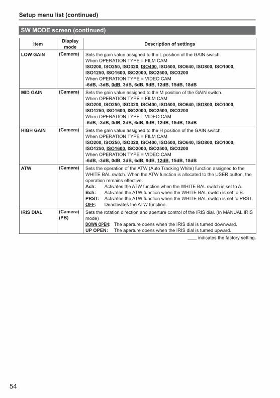
54
Setup menu list (continued)
SW MODE screen (continued)
Item Display mode Description of settings
LOW GAIN (Camera) Sets the gain value assigned to the L position of the GAIN switch. When OPERATION TYPE = FILM CAMISO200, ISO250, ISO320, ISO400, ISO500, ISO640, ISO800, ISO1000, ISO1250, ISO1600, ISO2000, ISO2500, ISO3200When OPERATION TYPE = VIDEO CAM-6dB, -3dB, 0dB, 3dB, 6dB, 9dB, 12dB, 15dB, 18dB
MID GAIN (Camera) Sets the gain value assigned to the M position of the GAIN switch.When OPERATION TYPE = FILM CAMISO200, ISO250, ISO320, ISO400, ISO500, ISO640, ISO800, ISO1000, ISO1250, ISO1600, ISO2000, ISO2500, ISO3200When OPERATION TYPE = VIDEO CAM-6dB, -3dB, 0dB, 3dB, 6dB, 9dB, 12dB, 15dB, 18dB
HIGH GAIN (Camera) Sets the gain value assigned to the H position of the GAIN switch. When OPERATION TYPE = FILM CAMISO200, ISO250, ISO320, ISO400, ISO500, ISO640, ISO800, ISO1000, ISO1250, ISO1600, ISO2000, ISO2500, ISO3200When OPERATION TYPE = VIDEO CAM-6dB, -3dB, 0dB, 3dB, 6dB, 9dB, 12dB, 15dB, 18dB
ATW (Camera) Sets the operation of the ATW (Auto Tracking White) function assigned to the WHITE BAL switch. When the ATW function is allocated to the USER button, the operation remains effective. Ach: Activates the ATW function when the WHITE BAL switch is set to A. Bch: Activates the ATW function when the WHITE BAL switch is set to B. PRST: Activates the ATW function when the WHITE BAL switch is set to PRST. OFF: Deactivates the ATW function.
IRIS DIAL (Camera)(PB)
Sets the rotation direction and aperture control of the IRIS dial. (In MANUAL IRIS mode)DOWN OPEN: The aperture opens when the IRIS dial is turned downward.UP OPEN: The aperture opens when the IRIS dial is turned upward.
indicates the factory setting.
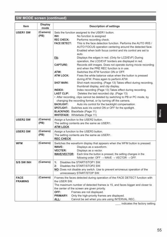
55
Men
u
Item Display mode Description of settings
USER1 SW (Camera)(PB)
Sets the function assigned to the USER1 button. INH: No function is assignedREC CHECK: Performs recording check.FACE DETECT: This is the face detection function. Performs the AUTO IRIS /
AUTO FOCUS operation centering around the detected face. Enabled when both focus control and iris control are set to auto.
FA: Displays the edges in red. (Only for LCD/EVF) During operation, the LCD/EVF borders are displayed in red.
CAPTURE: Records still images. Does not operate during movie recording and when the PRE REC function is in use.
ATW: Switches the ATW function ON or OFF.ATW LOCK: Fixes the white balance value when the button is pressed
during ATW. Press again to perform ATW.SHOT MARK: Shot mark recording. (Page 13) Takes effect during recording,
thumbnail display, and clip display. INDEX: Index recording (Page 13) Takes effect during recording.LAST CLIP: Deletes the last recorded clip. (Page 13)
After recording, clips cannot be deleted by switching to PB or PC mode, by •changing the recording format, or by turning off the camera.
BACKLIGHT: Auto iris control for the backlight compensation.SPOTLIGHT: Switches auto iris control ON or OFF for the spotlight.BLACKFADE: Blackfade (Page 11)WHITEFADE: Whitefade (Page 11)
USER2 SW (Camera)(PB)
Assign a function to the USER2 button. The setting contents are the same as USER1.ATW LOCK
USER3 SW (Camera)(PB)
Assign a function to the USER3 button. The setting contents are the same as USER1.REC CHECK
WFM (Camera) Switches the waveform display that appears when the WFM button is pressed. WAVE: Displays as a waveform.VECTER: Displays as a vector.WAVE/VECTOR: Each time the button is pressed, the setting changes in the
followingorder:OFF→WAVE→VECTOR→OFF.
S/S SW INH (Camera) 1: Disables the START/STOP1 SW. 2: Disables the START/STOP2 SW. NO: Does not disable any switch. Use to prevent erroneous operation of the
unnecessary START/STOP SW.
FACE FRAMING
(Camera) Frames the faces detected during operation of the FACE DETECT function with the USER SW. The maximum number of detected frames is 15, and faces bigger and closer to the center of the screen are given priority. OFF: Frames are not displayed.PRIMARY: Only the high-priority frames are displayed.ALL: Cannot be set when you are using INTERVAL REC.
indicates the factory setting.
SW MODE screen (continued)
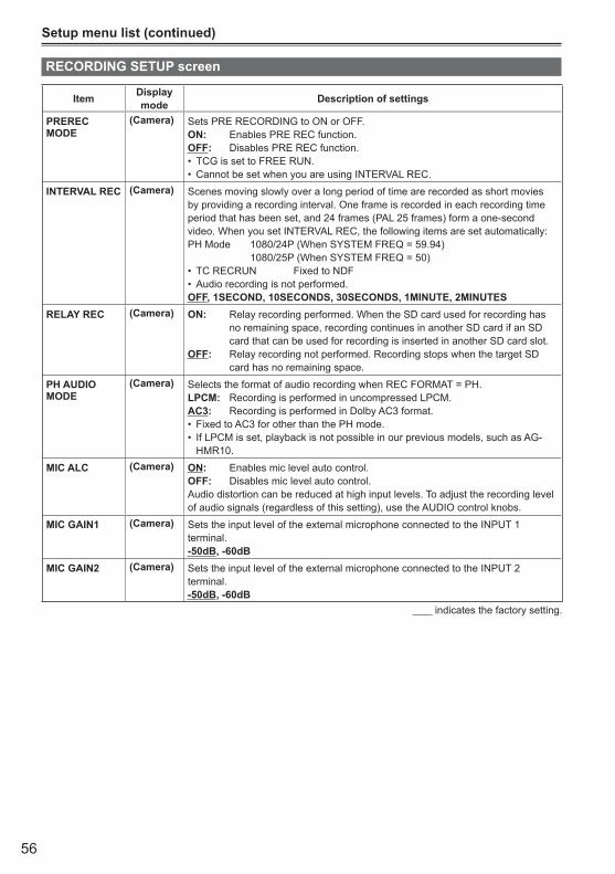
56
Setup menu list (continued)
RECORDING SETUP screen
Item Display mode Description of settings
PREREC MODE
(Camera) Sets PRE RECORDING to ON or OFF.ON: Enables PRE REC function.OFF: Disables PRE REC function.
TCG is set to FREE RUN.•Cannot be set when you are using INTERVAL REC.•
INTERVAL REC (Camera) Scenes moving slowly over a long period of time are recorded as short movies by providing a recording interval. One frame is recorded in each recording time period that has been set, and 24 frames (PAL 25 frames) form a one-second video. When you set INTERVAL REC, the following items are set automatically:PH Mode 1080/24P (When SYSTEM FREQ = 59.94)
1080/25P (When SYSTEM FREQ = 50)TC RECRUN Fixed to NDF•Audio recording is not performed. •
OFF, 1SECOND, 10SECONDS, 30SECONDS, 1MINUTE, 2MINUTESRELAY REC (Camera) ON: Relay recording performed. When the SD card used for recording has
no remaining space, recording continues in another SD card if an SD card that can be used for recording is inserted in another SD card slot.
OFF: Relay recording not performed. Recording stops when the target SD card has no remaining space.
PH AUDIO MODE
(Camera) Selects the format of audio recording when REC FORMAT = PH.LPCM: Recording is performed in uncompressed LPCM.AC3: Recording is performed in Dolby AC3 format.
Fixed to AC3 for other than the PH mode.•If LPCM is set, playback is not possible in our previous models, such as AG-•HMR10.
MIC ALC (Camera) ON: Enables mic level auto control.OFF: Disables mic level auto control.Audio distortion can be reduced at high input levels. To adjust the recording level of audio signals (regardless of this setting), use the AUDIO control knobs.
MIC GAIN1 (Camera) Sets the input level of the external microphone connected to the INPUT 1 terminal. -50dB, -60dB
MIC GAIN2 (Camera) Sets the input level of the external microphone connected to the INPUT 2 terminal. -50dB, -60dB
indicates the factory setting.
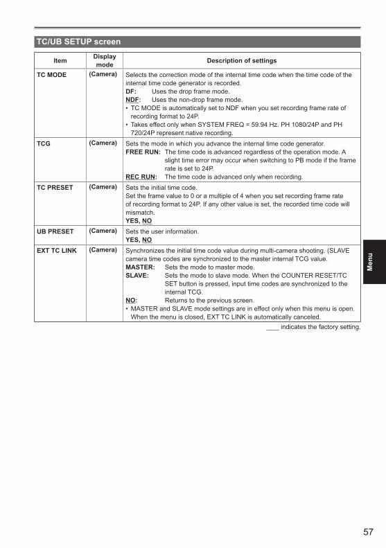
57
Men
u
TC/UB SETUP screen
Item Display mode Description of settings
TC MODE (Camera) Selects the correction mode of the internal time code when the time code of the internal time code generator is recorded. DF: Uses the drop frame mode.NDF: Uses the non-drop frame mode.
TC MODE is automatically set to NDF when you set recording frame rate of •recording format to 24P. Takes effect only when SYSTEM FREQ = 59.94 Hz. PH 1080/24P and PH •720/24P represent native recording.
TCG (Camera) Sets the mode in which you advance the internal time code generator.FREE RUN: The time code is advanced regardless of the operation mode. A
slight time error may occur when switching to PB mode if the frame rate is set to 24P.
REC RUN: The time code is advanced only when recording.
TC PRESET (Camera) Sets the initial time code.Set the frame value to 0 or a multiple of 4 when you set recording frame rate of recording format to 24P. If any other value is set, the recorded time code will mismatch. YES, NO
UB PRESET (Camera) Sets the user information. YES, NO
EXT TC LINK (Camera) Synchronizes the initial time code value during multi-camera shooting. (SLAVE camera time codes are synchronized to the master internal TCG value.MASTER: Sets the mode to master mode. SLAVE: Sets the mode to slave mode. When the COUNTER RESET/TC
SET button is pressed, input time codes are synchronized to the internal TCG.
NO: Returns to the previous screen.MASTER and SLAVE mode settings are in effect only when this menu is open. •When the menu is closed, EXT TC LINK is automatically canceled.
indicates the factory setting.
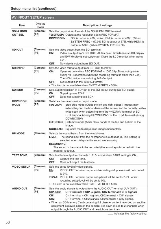
58
Setup menu list (continued)
AV IN/OUT SETUP screen
Item Display mode Description of settings
SDI & HDMI OUT SEL
(Camera)(PB)
Sets the output video format of the SDI&HDMI OUT terminal. 1080i/720P: Output at the resolution set in REC FORMAT. DOWNCONV: SDI is output at 480i, while HDMI is output at 480p. (When
SYSTEM FREQ = 59.94) SDI is output at 576i, while HDMI is output at 576p. (When SYSTEM FREQ = 50)
SDI OUT (Camera)(PB)
Sets the video output from the SDI terminal. ON: Video is output from SDI OUT. At this point, simultaneous LCD display
and EVF display is not supported. Close the LCD monitor when using EVF.
OFF: No video is output from SDI OUT.
SDI 24PsF (Camera)(PB)
Sets the video format output from SDI OUT to 24PsF.ON: Operates only when REC FORMAT = 1080 24p. Does not operate
during VFR operation (when the recording format is other than 24p). The HDMI output stops during 24Psf output.
OFF: SDI output is in the 1080 60i format.This item is not available when SYSTEM FREQ = 50Hz.•
SDI EDH (Camera)(PB)
Sets superimposition of EDH on to the SDI output during SD SDI output.ON: Superimposes EDH.OFF: Does not superimpose EDH.
DOWNCON MODE
(Camera)(PB)
Switches down-conversion output mode.SIDE CROP: Side-crop mode (Crops the left and right edges.) Images may
extend beyond the boundaries of the screen and be partially unable to be seen when outputting from the +H227A/V terminal or SDI OUT terminal (during DOWNCONV), or the HDMI terminal (during DOWNCONV).
LETTER BOX: Letterbox mode (Adds black bands at the top and bottom of the image.
SQUEEZE: Squeeze mode (Squeezes images horizontally.
HP MODE (Camera) Selects the sound heard from the headphones. LIVE: The sound input from the microphone is output as is. This setting is
selected when delays in the sound are annoying.RECORDING: The sound in the status to be recorded (the sound synchronized with the
images) is output.
TEST TONE (Camera) Sets test tone output to channels 1, 2, 3, and 4 when BARS setting is ON.ON: Outputs the test tone.OFF: Does not output the test tone.
VIDEO SETUP (Camera)(PB)
Sets the setup level of video signals.0%: VIDEO OUT terminal output and recording setup levels will both be set
to 0%. 7.5%A: VIDEO OUT terminal output setup level will be set to 7.5%, while
recording setup level will be set to 0%. This item is not available when SYSTEM FREQ = 50Hz.•
AUDIO OUT (Camera)(PB)
Sets the audio signals to output from the AUDIO OUT terminal (A/V OUT).CH1/CH2: CH1 terminal = CH1 signals, CH2 terminal = CH2 signalsCH1: CH1 terminal = CH1 signals, CH2 terminal = CH1 signalsCH2: CH1 terminal = CH2 signals, CH2 terminal = CH2 signals
When an SD Memory Card containing 5.1 channel content recorded on another •equipment is played back on the camera, it is down-mixed to 2 channels when output through the AUDIO OUT and headphone terminals.
indicates the factory setting.
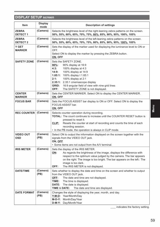
59
Men
u
DISPLAY SETUP screen
Item Display mode Description of settings
ZEBRA DETECT 1
(Camera) Selects the brightness level of the right-leaning zebra patterns on the screen. 50%, 55%, 60%, 65%, 70%, 75%, 80%, 85%, 90%, 95%, 100%, 105%
ZEBRA DETECT 2
(Camera) Selects the brightness level of the left-leaning zebra patterns on the screen. 50%, 55%, 60%, 65%, 70%, 75%, 80%, 85%, 90%, 95%, 100%, 105%
Y GET MARKER
(Camera) Sets the display of the marker used for displaying the luminance level to ON or OFF. Select ON to display the marker by pressing the ZEBRA button.ON, OFF
SAFETY ZONE (Camera) Sets the SAFETY ZONE. 90%: 90% display at 16:94:3: 100% display at 4:314:9: 100% display at 14:91.85:1: 100% display t 1.85:12:1: 100% display at 2:12.35:1: 2.35:1 cinemascope displayGRID: 16:9 angular field of view with nine grid linesOFF: The SAFETY ZONE is not displayed.
CENTER MARKER
(Camera) Sets the CENTER MARKER. Select ON to display the CENTER MARKER.ON, OFF
FOCUS BAR (Camera) Sets the FOCUS ASSIST bar display to ON or OFF. Select ON to display the FOCUS ASSIST bar.ON, OFF
REC COUNTER (Camera) Selects counter operation during recording. TOTAL: The count continues to increase until the COUNTER RESET button is
pressed to reset it.CLIP: Resets the counter at start of recording and counts the time of each
recording session.In the PB mode, the operation is always in CLIP mode. •
VIDEO OUT OSD
(Camera)(PB)
Select ON to output the information displayed on the screen together with the signals from the VIDEO OUT jack.ON, OFF
Some items are not output from the A/V terminal.•
IRIS METER (Camera) Sets the display of the IRIS METER. ON: As regards the brightness of the image, displays the difference with
respect to the optimum value judged by the camera. The bar appears on the right: The image is too bright. The bar appears on the left:: The image is too dark.
OFF: The IRIS METER is not displayed.
DATE/TIME (Camera)(PB)
Sets whether to display the date and time on the screen and whether to output from the VIDEO OUT jack.OFF: The date and time are not displayed. TIME: The time is displayed. DATE: The date is displayed.TIME & DATE: The date and time are displayed.
DATE FORMAT (Camera)(PB)
Changes the style of displaying the year, month, and day.Y-M-D: Year/Month/DayM-D-Y: Month/Day/YearD-M-Y: Day/Month/Year
indicates the factory setting.

60
Setup menu list (continued)
Item Display mode Description of settings
LEVEL METER (Camera)(PB)
Select ON to display the audio level meter.ON, OFF
ZOOM & FOCUS
(Camera) Selects the unit of zoom and focus values.OFF, NUMBER, mm/m, mm/feet
Use the mm/feet or mm/m display only as a general guideline because it is not •entirely accurate. When you are using a lens that has no communication connection between •the camera and lens through the use of a mount adaptor, the zoom and focus values are not displayed.
CARD & BATTERY
(Camera)(PB)
Select ON to display the remaining SD Memory Card recording capacity and remaining battery charge. ON, OFF
OTHER DISPLAY
(Camera) Select how much information to display on the viewfinder and LCD monitor.OFF, PARTIAL, ALL
LCD BACKLIGHT
(Camera)(PB)
Adjusts the backlight of the LCD monitor.+1, 0, - 1, - 2, - 3+1: The backlight becomes brighter.- 3: The backlight becomes the darkest.
LCD SET (Camera)(PB)
Adjusts the display level of images on the LCD monitor.BRIGHTNESSCOLORCONTRAST
EVF SET (Camera)(PB)
Adjusts the display level of images on the viewfinder. BRIGHTNESSCOLORCONTRAST
SELF SHOOT (Camera) Selects the LCD mirror mode for self-portrait shooting.Selecting MIRROR displays the left and right side of the LCD monitor image inverted during self-portrait shooting.NORMAL, MIRROR
EVF MODE (Camera)(PB)
Switches the screen display of images. AUTO: If you open the LCD monitor, images on the viewfinder disappear. ON: Images are always displayed on the viewfinder.
When SDI OUT = ON, regardless of this item, AUTO settings are operated •forcibly.
EVF COLOR (Camera) EVF COLOR (Camera) Switches viewfinder images to color or black and white. ON: ColorOFF: Black and white
indicates the factory setting.
DISPLAY SETUP screen (continued)

61
Men
u
CARD FUNCTIONS screen
Item Display mode Description of settings
CARD FORMAT
(Camera)(PB)
Formats the SD Memory Card.Slot1: Formats the SD Card inserted in Slot 1.Slot2: Formats the SD Card inserted in Slot 2.NO: Returns to the previous screen.
CARD STATUS (Camera)(PB)
Displays the SD Memory Card status. Slot1: Displays the information about the SD Card inserted in Slot 1.Slot2: Displays the information about the SD Card inserted in Slot 2.NO: Returns to the previous screen.
CLIP PROPERTY
(PB) Displays information about the selected clip. YES: Displays clip information.NO: Returns to the previous screen.
USER FILE screen
Item Display mode Description of settings
CARD READ (Camera)(PB)
Reads the user files saved on the SD Memory Card.Slot1: Reads the user files from the SD Card inserted in Slot 1.Slot2: Reads the user files from the SD Card inserted in Slot 2. NO: Returns to the previous screen.
CARD WRITE (Camera)(PB)
Saves the user files on the SD Memory Card. You can also add a title to the saved files. Slot1: Saves the user files on the SD Card inserted in Slot 1.Slot2: Saves the user files on the SD Card inserted in Slot 2.NO: Returns to the previous screen.
LOAD/SAVE/INIT
(Camera)(PB)
LOAD: Loads the settings in a previously stored user file.SAVE: Saves the updated user file settings.INIT: Returns the settings in the user file to factory settings.NO: Returns to the previous screen.
After a LOAD or INITIALIZE operation, turn OFF the POWER switch of the •camera and then turn it ON again to make the new settings available. The INITIALIZE operation does not change the TIME ZONE settings (Page 63).•
indicates the factory setting.
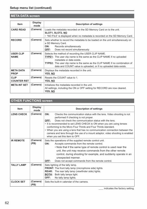
62
Setup menu list (continued)
Item Display mode Description of settings
CARD READ (Camera) Loads the metadata recorded on the SD Memory Card on to the unit.SLOT1, SLOT2, NO
“NO FILE’ is displayed when no metadata is recorded on the SD Memory Card.•
RECORD (Camera) Sets whether to record the metadata to be loaded on the unit simultaneously on a SD Memory Card.ON: Records simultaneouslyOFF: Does not record simultaneously
USER CLIP NAME
(Camera) Selects the method of recording the USER CLIP NAME.TYPE1: The user clip name is the same as the CLIP NAME if no uploaded
metadata or data exists.TYPE2: The user clip name is the same as the CLIP NAME if no combination of
data and COUNT value is uploaded, or if no uploaded data exists.
META DATA PROP
(Camera) Displays the metadata recorded in the unit.YES, NO
CLIP COUNTER RST
(Camera) Resets the COUNT value to 1. YES, NO
META INT SET (Camera) Initializes the metadata recorded in the unit.All settings, including the ON or OFF setting for RECORD are now cleared.YES, NO
OTHER FUNCTIONS screen
Item Display mode Description of settings
LENS CHECK (Camera) ON: Checks the communication status with the lens. Video shooting is not performed if checking is not proper.
OFF: Does not check the communication status with the lens.It is recommended to set LENS CHECK to ON when you are using lenses •conforming to the Micro Four Thirds and Four Thirds standard.When you are using a lens that has no communication connection between the •camera and lens through the use of a mount adaptor, video shooting is enabled when you set this item to OFF.
IR REMOTE (Camera)(PB)
Sets the operations of the supplied remote control unit.ON: Accepts commands from the remote control.
•Notethatifthesametypeofremotecontrolisusedneartheunit, the unit may receive commands from the other remote control, during shooting for example, and suddenly operate in an unexpected manner.
OFF: Does not accept commands from the remote control.
TALLY LAMP (Camera) Sets lighting of the tally lamp. FRONT: The front tally lamp (microphone side) lights.REAR: The rear tally lamp (viewfinder side) lights.BOTH: Both tally lamps light.OFF: No tally lamp lights.
CLOCK SET (Camera)(PB)
Sets the built-in calendar of the camera.
indicates the factory setting.
META DATA screen

63
Men
u
Item Display mode Description of settings
TIME ZONE (Camera)(PB)
Adds to or deducts from GMT the time value of -12:00 to +13:00 in 30-minute steps. (Refer to the table below.)+00:00
Time difference Area Time
difference Area
+ 00:00 Greenwich – 00:30– 01:00 Azores Islands – 01:30– 02:00 Mid-Atlantic – 02:30– 03:00 Buenos Aires – 03:30 Newfoundland Island– 04:00 Halifax – 04:30– 05:00 New York – 05:30– 06:00 Chicago – 06:30– 07:00 Denver – 07:30– 08:00 Los Angeles – 08:30– 09:00 Alaska – 09:30 Marquesas Islands– 10:00 Hawaii – 10:30– 11:00 Midway Island – 11:30– 12:00 Kwajalein + 12:30+ 13:00 + 11:30 Norfolk Island+ 12:00 New Zealand + 10:30 Lord Howe Island+ 11:00 Solomon Islands + 09:30 Darwin+ 10:00 Guam + 08:30+ 09:00 Tokyo + 07:30+ 08:00 Beijing + 06:30 Yangon+ 07:00 Bangkok + 05:30 Mumbai+ 06:00 Dacca + 04:30 Kabul+ 05:00 Islamabad + 03:30 Tehran+ 04:00 Abu Dhabi + 02:30+ 03:00 Moscow + 01:30+ 02:00 Eastern Europe + 00:30+ 01:00 Central Europe
POWER SAVE (Camera) Selects the power-saving mode when no operation is performed from the Operation lever, MENU button, AUDIO MON/ADV button, USER button, or START/STOP button for about five minutes when an SD Memory Card has been inserted in the CAM mode.ON: Power supply to the camera is turned OFF. OFF: Power supply to the camera is not turned OFF.
Even when POWER SAVE has been set to ON, the power supply does not •turn OFF when an SD Memory Card has not been inserted, when the camera-recorder is in the PB or PC mode, or when the AC adaptor is connected.
LANGUAGE (Camera)(PB)
Sets the Menu language. ENGLISH, Deutsch, Français, Italiano, Español
SYSTEM FREQ (Camera)(PB)
Sets the system frequency59.94Hz: NTSC region50Hz: PAL region
SYSTEM INFO (Camera) Displays the version of the system in this camera.
LENS INFO (Camera)(PB)
Displays the version of the Micro Four Thirds and Four Thirds lenses that have been installed.
MENU INIT (Camera) Returns the menu settings (scene files and user files) to factory default settings.The TIME ZONE settings do not return to factory default settings. •
indicates the factory setting.
OTHER FUNCTIONS screen (continued)

64
Setup menu list (continued)
Item Display mode Description of settings
OPERATION TIME
(Camera)(PB)
Displays the power-on time (a 5-digit figure).
UPDATE (Camera) Updates the system. For details on the update information, see our home page http://pro-av.panasonic.net/ .
LENS UPDATE (Camera) Updates the lens firmware. For details about the update information, see the home page of each lens manufacturer.
indicates the factory setting.
PLAY SETUP screen
Item Display mode Description of settings
PB FORMAT (PB) Sets the playback format. When SYSTEM FREQ = 59.94 Hz1080/60i (30P), 1080/24P, 720/60P(30P), 720/24PWhen SYSTEM FREQ = 50 Hz1080/50i(25P), 720/50P(25P)
The REC FORMAT setting in the CAM mode prior to migrating to the PB mode •becomes the default value of the PB FORMAT.
REPEAT PLAY (PB) ON, OFFWhen ON is selected, supported clips are played repeatedly.
RESUME PLAY (PB) ON, OFFWhen ON is selected, playback resumes from the video position where clip playback had stopped.
SKIP MODE (PB) Selects the starting position for cued playback after pausing. CLIP: Stops playback at the beginning of the previous clip.CLIP & INDEX: Stops at the beginning of the clip and the INDEX.
indicates the factory setting.
OTHER FUNCTIONS screen (continued)
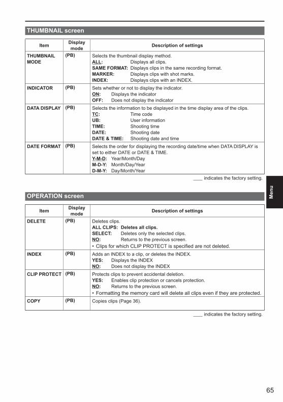
65
Men
u
THUMBNAIL screen
Item Display mode Description of settings
THUMBNAIL MODE
(PB) Selects the thumbnail display method. ALL: Displays all clips.SAME FORMAT: Displays clips in the same recording format. MARKER: Displays clips with shot marks.INDEX: Displays clips with an INDEX.
INDICATOR (PB) Sets whether or not to display the indicator. ON: Displays the indicatorOFF: Does not display the indicator
DATA DISPLAY (PB) Selects the information to be displayed in the time display area of the clips. TC: Time codeUB: User informationTIME: Shooting timeDATE: Shooting dateDATE & TIME: Shooting date and time
DATE FORMAT (PB) Selects the order for displaying the recording date/time when DATA DISPLAY is set to either DATE or DATE & TIME.Y-M-D: Year/Month/DayM-D-Y: Month/Day/YearD-M-Y: Day/Month/Year
indicates the factory setting.
OPERATION screen
Item Display mode Description of settings
DELETE (PB) Deletes clips.ALL CLIPS: Deletes all clips.SELECT: Deletes only the selected clips. NO: Returns to the previous screen.
Clips for which CLIP PROTECT is specified are not deleted. •INDEX (PB) Adds an INDEX to a clip, or deletes the INDEX.
YES: Displays the INDEXNO: Does not display the INDEX
CLIP PROTECT (PB) Protects clips to prevent accidental deletion. YES: Enables clip protection or cancels protection. NO: Returns to the previous screen.
Formatting the memory card will delete all clips even if they are protected. •COPY (PB) Copies clips (Page 36).
indicates the factory setting.
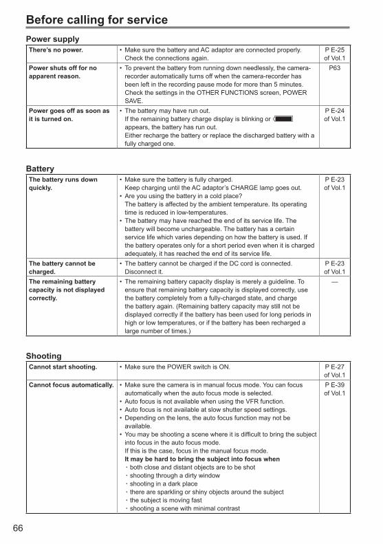
66
Before calling for servicePower supplyThere’s no power. Make sure the battery and AC adaptor are connected properly. •
Check the connections again.P E-25 of Vol.1
Power shuts off for no apparent reason.
To prevent the battery from running down needlessly, the camera-•recorder automatically turns off when the camera-recorder has been left in the recording pause mode for more than 5 minutes.Check the settings in the OTHER FUNCTIONS screen, POWER SAVE.
P63
Power goes off as soon as it is turned on.
The battery may have run out. •If the remaining battery charge display is blinking or appears, the battery has run out. Either recharge the battery or replace the discharged battery with a fully charged one.
P E-24 of Vol.1
BatteryThe battery runs down quickly.
Make sure the battery is fully charged. •Keep charging until the AC adaptor’s CHARGE lamp goes out.Are you using the battery in a cold place? •The battery is affected by the ambient temperature. Its operating time is reduced in low-temperatures.The battery may have reached the end of its service life. The •battery will become unchargeable. The battery has a certain service life which varies depending on how the battery is used. If the battery operates only for a short period even when it is charged adequately, it has reached the end of its service life.
P E-23 of Vol.1
The battery cannot be charged.
The battery cannot be charged if the DC cord is connected.•Disconnect it.
P E-23 of Vol.1
The remaining battery capacity is not displayed correctly.
The remaining battery capacity display is merely a guideline. To •ensure that remaining battery capacity is displayed correctly, use the battery completely from a fully-charged state, and charge the battery again. (Remaining battery capacity may still not be displayed correctly if the battery has been used for long periods in high or low temperatures, or if the battery has been recharged a large number of times.)
—
ShootingCannot start shooting. Make sure the POWER switch is ON.• P E-27
of Vol.1Cannot focus automatically. Make sure the camera is in manual focus mode. You can focus •
automatically when the auto focus mode is selected.Auto focus is not available when using the VFR function.•Auto focus is not available at slow shutter speed settings. •Depending on the lens, the auto focus function may not be •available.You may be shooting a scene where it is difficult to bring the subject •into focus in the auto focus mode. If this is the case, focus in the manual focus mode. It may be hard to bring the subject into focus when
both close and distant objects are to be shot āshooting through a dirty window āshooting in a dark place āthere are sparkling or shiny objects around the subject āthe subject is moving fast āshooting a scene with minimal contrast ā
P E-39 of Vol.1

67
Ref
eren
ce
RecordingCannot record even through the SD Memory Card is inserted correctly.
Isthewrite-protectswitchontheSDMemoryCardinthe“LOCK”•position? The card cannot be recorded to if the switch is in the “LOCK”position.Is the remaining memory available on the SD Memory Card •extremely low? Please save contents onto different media and delete unneeded data from the card, or use a new card instead.Has the SD Memory Card been correctly formatted? Alternatively, is •the card of a format that is incompatible with this camera? Reformat the card with the camera.8 MB to 16 MB SD Memory Cards cannot be used for shooting •movies.
P E-38 of Vol.1
P E-36 of Vol.1
P E-12 of Vol.1
Recording stops by itself. Is your SD Memory Card compatible with use for video recording? •Always use an SD Memory Card compatible with use for video recording.
P E-12 of Vol.1
EditingCannot read the data on the SD Memory Card.
Make sure the SD Memory Card is formatted correctly. •If it is not, format the card in the unit.
P E-36 of Vol.1
Cannot perform nonlinear editing.
Check the specifications of your computer and connecting cable.• P42
Cannot dub onto anexternal device.
Make sure the external device is connected correctly.• P42
DisplaysSomething is wrong withthe time code display.
The time code display may not register a regular count if a clip is •played in the reverse slow mode. This is normal.
—
PlaybackCannot play even when Ipress the play button.
Make sure the PB lamp is on (press the mode button). •No kind of playback operation can be performed unless this lamp is on.
P28
Mosaic-like noise appears when I cue or review a clip.
This noise is inherent to digital video technology. This is normal.• —
Images do not appear on the television even though I have connected the camera-recorder properly.
Make sure the input selector on your television is set to video input.•Read the television’s instructions carefully and select the correct video input connector for the camera-recorder.
—
Cannot hear any sound from the camera-recorder’s speaker.
You may have turned down the camera-recorder’s volume control •too far. Adjust the volume level using the AUDIO MON/ADV button +.
P40
(Continued on the next page)
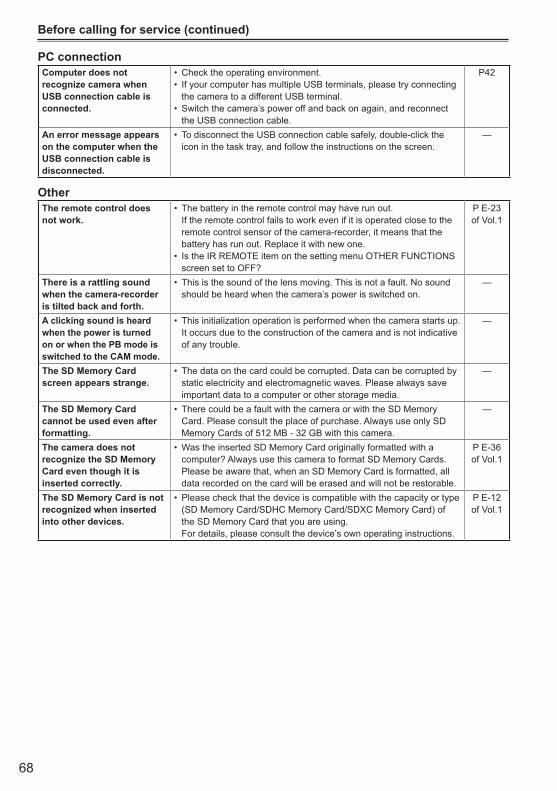
68
PC connectionComputer does not recognize camera when USB connection cable is connected.
Check the operating environment.•If your computer has multiple USB terminals, please try connecting •the camera to a different USB terminal.Switch the camera’s power off and back on again, and reconnect •the USB connection cable.
P42
An error message appears on the computer when the USB connection cable is disconnected.
To disconnect the USB connection cable safely, double-click the •icon in the task tray, and follow the instructions on the screen.
—
OtherThe remote control doesnot work.
The battery in the remote control may have run out. •If the remote control fails to work even if it is operated close to the remote control sensor of the camera-recorder, it means that the battery has run out. Replace it with new one.Is the IR REMOTE item on the setting menu OTHER FUNCTIONS •screen set to OFF?
P E-23 of Vol.1
There is a rattling sound when the camera-recorder is tilted back and forth.
This is the sound of the lens moving. This is not a fault. No sound •should be heard when the camera’s power is switched on.
—
A clicking sound is heard when the power is turned on or when the PB mode is switched to the CAM mode.
This initialization operation is performed when the camera starts up. •It occurs due to the construction of the camera and is not indicative of any trouble.
—
The SD Memory Card screen appears strange.
The data on the card could be corrupted. Data can be corrupted by •static electricity and electromagnetic waves. Please always save important data to a computer or other storage media.
—
The SD Memory Card cannot be used even after formatting.
There could be a fault with the camera or with the SD Memory •Card. Please consult the place of purchase. Always use only SD Memory Cards of 512 MB - 32 GB with this camera.
—
The camera does not recognize the SD Memory Card even though it is inserted correctly.
Was the inserted SD Memory Card originally formatted with a •computer? Always use this camera to format SD Memory Cards. Please be aware that, when an SD Memory Card is formatted, all data recorded on the card will be erased and will not be restorable.
P E-36 of Vol.1
The SD Memory Card is not recognized when inserted into other devices.
Please check that the device is compatible with the capacity or type •(SD Memory Card/SDHC Memory Card/SDXC Memory Card) of the SD Memory Card that you are using. For details, please consult the device’s own operating instructions.
P E-12 of Vol.1
Before calling for service (continued)
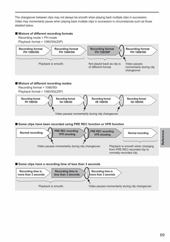
69
Ref
eren
ce
The changeover between clips may not always be smooth when playing back multiple clips in succession.Video may momentarily pause when playing back multiple clips in succession in circumstances such as those detailed below.
Mixture of different recording formats ■ Recording mode = PH mode Playback format = 1080/50i(25P)
Recording formatPH 1080/50i
Recording formatPH 1080/50i
Recording formatPH 1080/50i
Playback is smooth. Not played back as clip is of different format.
Video pauses momentarily during clip changeover.
Recording formatPH 720/50P
Mixture of different recording modes ■ Recording format = 1080/50i Playback format = 1080/50i(25P)
Video pauses momentarily during clip changeover.
Recording formatHA 1080/50i
Recording formatHE 1080/50i
Recording formatHA 1080/50i
Recording formatPH 1080/50i
Some clips have been recorded using PRE REC function or VFR function ■PRE REC recording
VFR shooting Normal recording
Video pauses momentarily during clip changeover. Playback is smooth when changing from PRE REC-recorded clip to normally-recorded clip.
PRE REC recordingVFR shootingNormal recording
Some clips have a recording time of less than 3 seconds ■Recording time is
more than 3 seconds
Playback is smooth. Video pauses momentarily during clip changeover.
Recording time is more than 3 seconds
Recording time is less than 3 seconds
70
Updating the firmware incorporated into the unitThe firmware can be updated using either of the following two methods.
1 Checking the current version of firmware and performing the update using the dedicated tool (P2_Status_Logger)PASS (P2 Asset Support System) is only available to customers who have completed customer registration with Panasonic.Log in to PASS and use the dedicated tool (P2_Status_Logger) to check the version information of the firmware on the unit and download links to pages containing the necessary firmware.For further information about downloading and using P2_Status_Logger, log in to PASS and refer to the relevant pages.Besides access to PASS, completing customer registration has a number of other benefits. For further details, refer to the PASS (P2 Asset Support System) website (http://panasonic.biz/sav/pass_e/).
2 Checking the current version of the firmware using the unit and performing the updateFrom the OTHER FUNCTIONS menu page, check the current version of firmware on the unit using the SYSTEN INFO screen. Then, access the website listed below for the latest firmware-related information and download firmware as required.
The update is completed by loading the downloaded file onto the unit via an SD memory card. For •further details about the updating methods, refer to the following website. http://pro-av.panasonic.net/Be sure to use a compatible SD memory card. The unit is compatible with SD memory cards based on •the SD, SDHC and SDXC standards. Also, be sure to format the memory card using the unit before use.
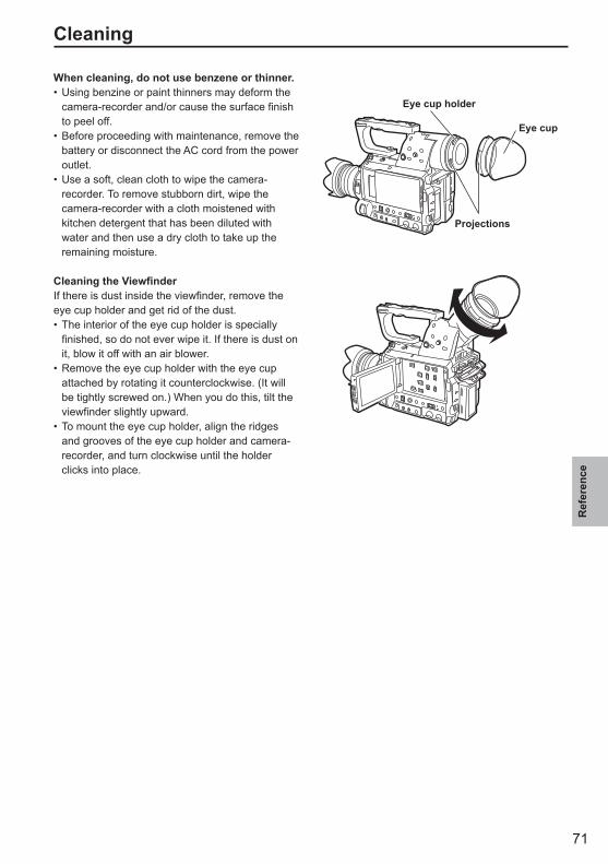
71
Ref
eren
ce
Cleaning
When cleaning, do not use benzene or thinner.Using benzine or paint thinners may deform the •camera-recorder and/or cause the surface finish to peel off.Before proceeding with maintenance, remove the •battery or disconnect the AC cord from the power outlet.Use a soft, clean cloth to wipe the camera-•recorder. To remove stubborn dirt, wipe the camera-recorder with a cloth moistened with kitchen detergent that has been diluted with water and then use a dry cloth to take up the remaining moisture.
Cleaning the ViewfinderIf there is dust inside the viewfinder, remove the eye cup holder and get rid of the dust.
The interior of the eye cup holder is specially •finished, so do not ever wipe it. If there is dust on it, blow it off with an air blower.Remove the eye cup holder with the eye cup •attached by rotating it counterclockwise. (It will be tightly screwed on.) When you do this, tilt the viewfinder slightly upward.To mount the eye cup holder, align the ridges •and grooves of the eye cup holder and camera-recorder, and turn clockwise until the holder clicks into place.
Eye cup holder
Eye cup
Projections
72
Storage PrecautionsBefore storing the camera-recorder, remove both the SD Memory Card and battery.Store all of these items in a place with low humidity and relatively constant temperature.[Recommended temperature range: 15°C to 25°C][Recommended relative humidity: 40% to 60%]
Camera-recorderWrap the camera-recorder in a soft cloth to keep •the dust off.
BatteryThe battery life is shortened in places with •extreme temperatures.Storing the battery in a location with oily vapors •or high dust concentrations may corrode the terminals or cause other damage, leading to malfunction.Keep metal objects (such as necklaces and •hairpins) away from the terminals. Short-circuiting may occur across the terminals, causing the battery to heat up, and you may seriously burn yourself if you touch the battery in this state.
SD Memory CardsAfter ejecting an SD Memory Card from the unit, •be absolutely sure to stow it in its own case.Do not leave SD Memory Cards in areas where •corrosive gases, etc. are present.Do not leave the cards inside vehicles, in places •exposed to direct sunlight or in other places where the temperature is high.Do not leave the cards where the humidity level •is high or where there are high concentrations of dust.
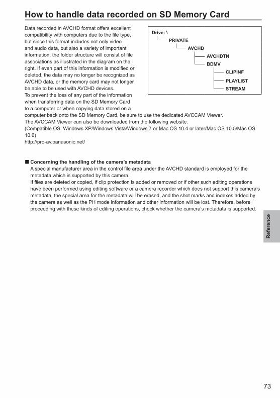
73
Ref
eren
ce
How to handle data recorded on SD Memory CardData recorded in AVCHD format offers excellent compatibility with computers due to the file type, but since this format includes not only video and audio data, but also a variety of important information, the folder structure will consist of file associations as illustrated in the diagram on the right. If even part of this information is modified or deleted, the data may no longer be recognized as AVCHD data, or the memory card may not longer be able to be used with AVCHD devices.To prevent the loss of any part of the information when transferring data on the SD Memory Card to a computer or when copying data stored on a computer back onto the SD Memory Card, be sure to use the dedicated AVCCAM Viewer. The AVCCAM Viewer can also be downloaded from the following website.(Compatible OS: Windows XP/Windows Vista/Windows 7 or Mac OS 10.4 or later/Mac OS 10.5/Mac OS 10.6)http://pro-av.panasonic.net/
Concerning the handling of the camera’s metadata ■ A special manufacturer area in the control file area under the AVCHD standard is employed for the
metadata which is supported by this camera. If files are deleted or copied, if clip protection is added or removed or if other such editing operations
have been performed using editing software or a camera recorder which does not support this camera’s metadata, the special area for the metadata will be erased, and the shot marks and indexes added by the camera as well as the PH mode information and other information will be lost. Therefore, before proceeding with these kinds of editing operations, check whether the camera’s metadata is supported.
Drive: \PRIVATE
AVCHDAVCHDTNBDMV
CLIPINF
PLAYLISTSTREAM

2010