Voltage Probe Manual and Data North Star High … Probe Manual and Data North Star High Voltage,...
8
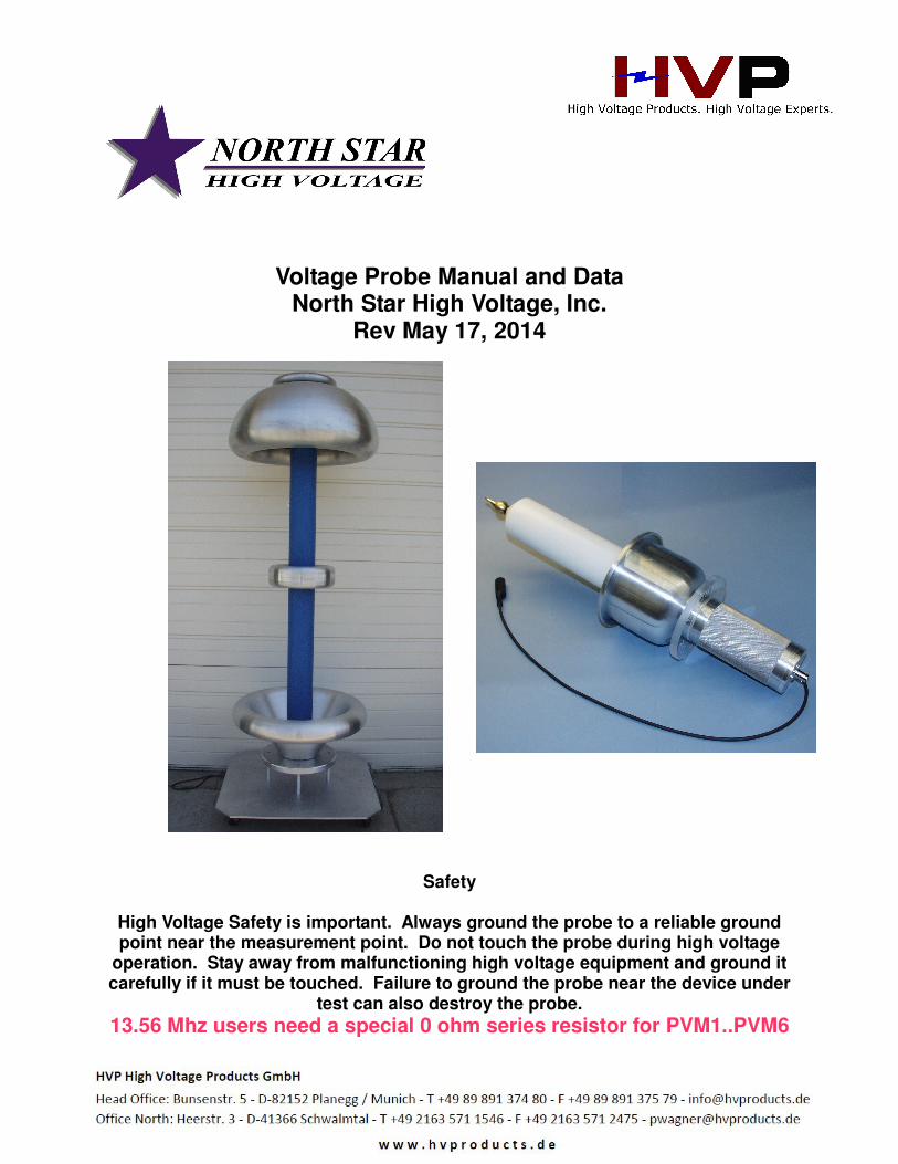
Voltage Probe Manual and Data North Star High Voltage, Inc. Rev May 17, 2014 Safety High Voltage Safety is important. Always ground the probe to a reliable ground point near the measurement point. Do not touch the probe during high voltage operation. Stay away from malfunctioning high voltage equipment and ground it carefully if it must be touched. Failure to ground the probe near the device under test can also destroy the probe. 13.56 Mhz users need a special 0 ohm series resistor for PVM1..PVM6
Transcript of Voltage Probe Manual and Data North Star High … Probe Manual and Data North Star High Voltage,...
Voltage Probe Manual and Data North Star High Voltage, Inc.
Rev May 17, 2014
Safety
High Voltage Safety is important. Always ground the probe to a reliable ground point near the measurement point. Do not touch the probe during high voltage
operation. Stay away from malfunctioning high voltage equipment and ground it carefully if it must be touched. Failure to ground the probe near the device under
test can also destroy the probe. 13.56 Mhz users need a special 0 ohm series resistor for PVM1..PVM6
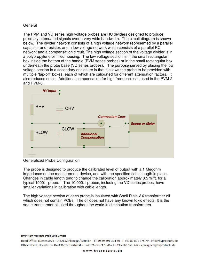
General The PVM and VD series high voltage probes are RC dividers designed to produce precisely attenuated signals over a very wide bandwidth. The circuit diagram is shown below. The divider network consists of a high voltage network represented by a parallel capacitor and resistor, and a low voltage network which consists of a parallel RC network and a compensation circuit. The high voltage section of the voltage divider is in a polypropylene oil filled housing. The low voltage section is in the small rectangular box inside the bottom of the handle (PVM series probes) or in the small rectangular box underneath the probe base (VD series probes). The purpose served by placing the low voltage section in a secondary enclosure is that it allows the probe to be provided with multiple “tap-off” boxes, each of which are calibrated for different attenuation factors. It also reduces noise. Additional compensation for high frequencies is used in the PVM-2 and PVM-6.
Generalized Probe Configuration The probe is designed to produce the calibrated level of output with a 1 Megohm impedance on the measurement device, and with the specified cable length in place. Changes in cable length tend to change the calibration approximately 0.5 %/ft. for a typical 1000:1 probe. The 10,000:1 probes, including the VD series probes, have smaller variations in calibration with cable length. The high voltage section of each probe is insulated with Shell Diala-AX transformer oil which does not contain PCBs. The oil does not have any known toxic effects. It is the same transformer oil used throughout the world in distribution transformers.
RHV CHV
RLOWCLOW
Scope or Meter
Connection Coax
AdditionalCompensation
HV Input

Input Impedance for Standard Operation Standard probes are designed to operate into a 1 megohm oscilloscope. Operation into higher impedance devices such as multi-meters requires a parallel resistance for accurate measurement. For example, a 1.111 Megohm resistance can be placed in parallel with a yellow Fluke meter (10 Megohm input) to produce a 1 Megohm input impedance. Operation into lower impedance equipment requires factory changes. Read the manual of your measuring instrument to determine its input impedance since many meter manufacturers use different input impedances on different meter scales. Erroneous readings will result with all probes (not just our probes) when the wrong measurement impedance is used. Proximity Effect and Exclusion Zone for VD and PVM11/12 Probes The “proximity effect” (change in calibration when the probe is near ground or near a high voltage node) has been reduced or eliminated in all NS probes. Good practice and high voltage safety still dictate that the probe should be spaced away from other conductors by a distance of at least 3 mm/kV (15 cm if the DC voltage is 50 kV). This is particularly true of DC voltage and repetitive AC voltage. A high frequency (f>50 Hz) calibration shift of about 0.5 - 1 % is possible if conductors are closer. Proximity Effect for PVM-1 – PVM-6 The PVM-1 – PVM-6 use a unique shielded design which both reduces proximity effects and increases the “speed” of measurement into the low nanosecond regime. Proximity effect at reasonable distances (15 cm) are too low to measure in the PVM1- PVM6 probes. High Frequency Measurements It may be necessary to improve the grounding of the probe in order to clean up noise in very high voltage, high frequency (>20 Mhz) measurements. Specifically, a wide area ground from the bottom of the probe, or additional individual grounds may be required. It may also be necessary to further shield the probe cables at the highest frequencies. The cause of noise is often the ground loop which results if the probe cable carries some of the ground current. Inductive isolators on the probe signal cable can also be helpful in “choking” ground currents. Note that the impedance presented to the load at 50 Mhz with a probe with 8 pf. Input capacitance is only 400 ohms, so currents matter at high frequencies. Connections In general, the ground clip lead should be connected to the ground of the equipment under test, and the tip of the probe should be connected to the voltage source for PVM series probes. For VD series probes, the signal is connected to the top of the probe, and the ground is connected to the base. At high frequency, the inductance of the

ground path must also be minimized. One method of improving high speed measurement is to use multiple grounds in addition to the black fly lead provided. The cylindrical ground shield can also be used for ground connections. Wide area and large diameter conductors can be helpful in reducing inductance which is important above 10 Mhz Connections should be made with the equipment to be measured turned off. The BNC output cable should be connected directly to the oscilloscope, and in general the oscilloscope should be grounded. An RG-223 cable (double shielded cable) is provided with all probes. The double shielded cable is essential at high frequencies and it is advantageous at low frequencies. Any 50 ohm (or 93 ohm if appropriate) cable can be used to connect to the measurement instrument as long as that cable has the right capacitance, but single shielded cables have more noise. It is important to avoid setups where the current of the source returns through the ground shield of the probe. The probe is not designed for this, and the IR drop over the cable appears as an erroneous signal at the oscilloscope. Changing the Cable We recommend that if a different cable than originally supplied is to be used, it should be made from RG-223 cable (except for 93 ohm cable probes) and kept to the same length as the original cable. Connectors can be placed in this cable (for example for penetrating screen room walls). Double shielded cables (RG-223) reduce spurious noise, leading to better performance. RG-223 has a capacitance of ~ 30 pf/ft. Troubleshooting The repair of most problems with the probe will lead to a requirement for re-calibration. If there is a problem, dis-assembly of the probe high voltage section is not recommended. Except in unusual situations, North Star will repair the probe without question if it is under warranty. It is much easier for us to ascertain the problem if the probe has not been modified by the user when it is returned to us. If the probe has no signal output, but is not shorted to ground, the problem may be a poor connection in the tap-off box. The tap-off box can be inspected, and if wires are loose they should be reconnected. Do not adjust the potentiometers in the tap-off box, or re-calibration will be required. The largest source of problems is systems which have an unexpected input impedance different from 1 Meg (subject to the presence of the switch option).

Black Resistor – Repetition Rate and Average Power Limitations The 82 ohm black resistor on the "nose" of the PVM-1 – PVM-6 probes damps >100 Mhz transients. However it is dissipative at fast risetimes and high rep rates and high continuous AC frequencies. Because of this problem, the resistor is removable and replaceable. The formula below describes the maximum frequency of use. T is the risetime and V is the peak voltage on the fast slope F <106*T(ns)/V(kV)2 (fast pulse measurements) So for example at 5 ns risetime, and 30 kV (6 kV/ns) the resistor will start to overheat at 5.5 kHz. For AC measurements with a duty cycle D, the derating of the black resistor is: F(Hz)*Vpk(kV)< 7*106/D1/2 So the resistor will reach its limit for a continuous wave (D=1) at 7 kV peak at 1 Mhz. If there are bursts of duty 1 % the resistor limit rises to 22 kV at 10 Mhz.

Probe Voltage in Various Frequency Ranges and Probe Derating All high voltage probes must be derated due to high frequency (i.e., high RMS currents and dissipation) and other effects. The following information is a guideline, although many high voltage systems have their own unique requirements which fall outside these guidelines. Derating applies to the CW frequency. Reduced duty cycle usually eliminates the requirement for derating. For pulses the horizontal axis is rep rate Application to AC up to 400 Hz. AC RMS operating voltage = DC voltage/1.41
10 100 1000 10000 100000
0
0.2
0.4
0.6
0.8
1
1.2
CW Derating
Derating relaxed for reduced duty
Derating(PVM1-PVM6)
Derating VD, PVM12
F(kHz)
Dera
ting F
acto
r
01
Figure 1 CW High Frequency Derating. In general the derating can be increased linearly as
the duty is decreased below 1.
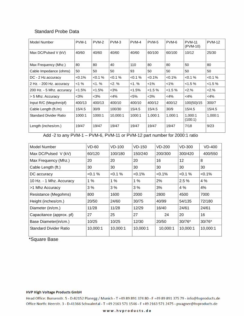
Standard Probe Data
Model Number PVM-1 PVM-2 PVM-3 PVM-4 PVM-5 PVM-6 PVM-11 (PVM-10)
PVM-12
Max DC/Pulsed V (kV)
40/60 40/60 40/60 40/60 60/100 60/100 10/12 25/30
Max Frequency (Mhz.) 80 80 40 110 80 80 50 80
Cable Impedance (ohms) 50 50 50 93 50 50 50 50
DC - 2 Hz.accuracy <0.1% <0.1 % <0.1 % <0.1 % <0.1% <0.1% <0.1 % <0.1 %
2 Hz. - 200 Hz. accuracy <1 % <1. % <2. % <1. % <1% <1% <1.5 % <1.5 %
200 Hz. - 5 Mhz. accuracy <1.5% <1.5% <3% <1.5% <1.5 % <1.5 % <2.% <2.%
> 5 Mhz. Accuracy <3% <3% <4% <5% <3% <4% <4% <4%
Input R/C (Megohm/pf) 400/13 400/13 400/10 400/10 400/12 400/12 100(50)/15 300/7
Cable Length (ft./m) 15/4.5 30/9 100/30 15/4.5 15/4.5 30/9 15/4.5 15/4.5
Standard Divider Ratio 1000:1 1000:1 10,000:1 1000:1 1,000:1 1,000:1 1,000:1 (100:1)
1,000:1
Length (inches/cm.) 19/47 19/47 19/47 19/47 19/47 19/47 7/18 9/23
Add -2 to any PVM-1 – PVM-6, PVM-11 or PVM-12 part number for 2000:1 ratio
Model Number VD-60 VD-100 VD-150 VD-200 VD-300 VD-400
Max DC/Pulsed V (kV) 60/120 100/180 150/240 200/300 300/420 400/550
Max Frequency (Mhz.) 20 20 20 16 12 8
Cable Length (ft.) 30 30 30 30 30 30
DC accuracy <0.1 % <0.1 % <0.1% <0.1% <0.1 % <0.1%
10 Hz. - 1 Mhz. Accuracy 1 % 1 % 1 % 2% 2.5 % 4 %
>1 Mhz Accuracy 3 % 3 % 3 % 3% 4 % 4%
Resistance (Megohms) 800 1600 2000 2800 4500 7000
Height (inches/cm.) 20/50 24/60 30/75 40/99 54/135 72/180
Diameter (in/cm.) 11/28 11/28 12/29 16/40 24/61 24/61
Capacitance (approx. pf) 27 25 27 24 20 16
Base Diameter(in/cm.) 10/25 10/25 12/30 20/50 30/76* 30/76*
Standard Divider Ratio 10,000:1 10,000:1 10,000:1 10,000:1 10,000:1
10,000:1
*Square Base
Examples of Applicability of Pulse Voltage Rating:
Full pulse rating at 1 Hz/10 usec pulse duration or shorter 1.5 X DC for VD series to 300 Hz/10 usec pulse duration 1.25 X DC for VD series to 4 kHz/10 usec pulse duration 1.25 X DC for PVM series to 300 Hz/10 usec pulse duration
The transition between pulse and DC is not well defined but lies somewhere between 10 usec and 1000 usec. Warranty The probe is warranted against defects in parts and workmanship for one (1) year after the ship date from North Star. We will repair the probe if an electrical failure occurs during the first six (6) months after shipping irrespective of the cause of the fault. Shipping from the customer site to North Star will be paid by the customer, and shipping from North Star to the customer will be paid by North Star. North Star will judge whether expedited means of shipping are required. Mechanical damage due to dropping the probe and extreme thermal damage (melting the probe) may not be covered and should be discussed with North Star before returning the probe. Shipping damage should be reported to North Star immediately. Please do not open the probe high voltage section if warranty repairs are going to be requested. This increases the work required to repair the probe, and is not effective. Additional Resources If you need a pulsed power formula try our pulsed power formulary. Download our well-known Pulsed Power Formulary at our web site: http://www.highvoltageprobes.com/downloads.html Very high voltage pulsed measurements with capacitive sensors and integrators - coming soon at http://www.highvoltageprobes.com/downloads.html