VLT Micro Drive FC 51 Programming Guide - radion.co.il · Before touching any potentially live...
83
Contents 1. Safety 3 Safety Instructions 3 Approvals 3 General Warning 3 Avoid unintended Start 4 Before Commencing Repair Work 5 2. Introduction 7 Type Code 7 3. Programming 9 How to Programme 9 Programming with MCT-10 9 Programming with LCP 11 or LCP 12 9 Status Menu 11 Quick Menu 11 Main Menu 12 4. Parameter Descriptions 13 Parameter group 0: Operation/Display 13 Parameter Group 1: Load/Motor 18 Parameter Group 2: Brakes 27 Parameter Group 3: Reference/Ramps 30 Parameter Group 4: Limits/Warnings 36 Parameter Group 5: Digital In/Out 39 Parameter Group 6: Analogue In/Out 44 Parameter Group 7: Controllers 50 Parameter Group 8: Communication 52 Parameter Group 13: Smart Logic 57 Parameter Group 14: Special Functions 65 Parameter Group 15: Drive Information 68 Parameter Group 16: Data Readouts 71 5. Parameter Lists 77 6. Troubleshooting 81 Index 82 VLT Micro Drive FC 51 Contents MG.02.C2.02 - VLT ® is a registered Danfoss trademark 1
Transcript of VLT Micro Drive FC 51 Programming Guide - radion.co.il · Before touching any potentially live...

Contents
1. Safety 3
Safety Instructions 3
Approvals 3
General Warning 3
Avoid unintended Start 4
Before Commencing Repair Work 5
2. Introduction 7
Type Code 7
3. Programming 9
How to Programme 9
Programming with MCT-10 9
Programming with LCP 11 or LCP 12 9
Status Menu 11
Quick Menu 11
Main Menu 12
4. Parameter Descriptions 13
Parameter group 0: Operation/Display 13
Parameter Group 1: Load/Motor 18
Parameter Group 2: Brakes 27
Parameter Group 3: Reference/Ramps 30
Parameter Group 4: Limits/Warnings 36
Parameter Group 5: Digital In/Out 39
Parameter Group 6: Analogue In/Out 44
Parameter Group 7: Controllers 50
Parameter Group 8: Communication 52
Parameter Group 13: Smart Logic 57
Parameter Group 14: Special Functions 65
Parameter Group 15: Drive Information 68
Parameter Group 16: Data Readouts 71
5. Parameter Lists 77
6. Troubleshooting 81
Index 82
VLT Micro Drive FC 51 Contents
MG.02.C2.02 - VLT® is a registered Danfoss trademark 1

1. Safety VLT Micro Drive FC 51
2 MG.02.C2.02 - VLT® is a registered Danfoss trademark
1

1. Safety
1.1.1. High Voltage Warning
The voltage of the frequency converter is dangerous whenever it is connected tomains. Incorrect installation of the motor or frequency converter may cause damageto the equipment, serious injury or death. Consequently, it is essential to complywith the instructions in this manual as well as local and national rules and safetyregulations.
1.1.2. Safety Instructions
• Make sure the frequency converter is properly connected to earth.
• Do not remove mains connections, motor connections or other power connections whilethe frequency converter is connected to power.
• Protect users against supply voltage.
• Protect the motor against overloading according to national and local regulations.
• The earth leakage current exceeds 3.5 mA.
• The [OFF] key is not a safety switch. It does not disconnect the frequency converter frommains.
1.1.3. Approvals
1.1.4. General Warning
Warning:Touching the electrical parts may be fatal - even after the equipment has been dis-connected from mains.Also make sure that other voltage inputs have been disconnected, (linkage of DCintermediate circuit).Be aware that there may be high voltage on the DC link even when the LEDs areturned off.Before touching any potentially live parts of the VLT Micro Drive, wait at least 4minutes for all sizes.Shorter time is allowed only if indicated on the nameplate for the specific unit.
VLT Micro Drive FC 51 1. Safety
MG.02.C2.02 - VLT® is a registered Danfoss trademark 3
1
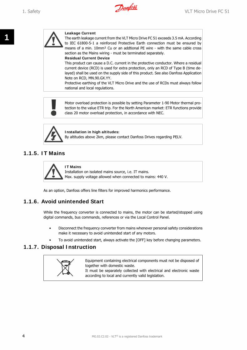
Leakage CurrentThe earth leakage current from the VLT Micro Drive FC 51 exceeds 3.5 mA. Accordingto IEC 61800-5-1 a reinforced Protective Earth connection must be ensured bymeans of a min. 10mm² Cu or an addtional PE wire - with the same cable crosssection as the Mains wiring - must be terminated separately.Residual Current DeviceThis product can cause a D.C. current in the protective conductor. Where a residualcurrent device (RCD) is used for extra protection, only an RCD of Type B (time de-layed) shall be used on the supply side of this product. See also Danfoss ApplicationNote on RCD, MN.90.GX.YY.Protective earthing of the VLT Micro Drive and the use of RCDs must always follownational and local regulations.
Motor overload protection is possible by setting Parameter 1-90 Motor thermal pro-tection to the value ETR trip. For the North American market: ETR functions provideclass 20 motor overload protection, in accordance with NEC.
Installation in high altitudes:By altitudes above 2km, please contact Danfoss Drives regarding PELV.
1.1.5. IT Mains
IT MainsInstallation on isolated mains source, i.e. IT mains.Max. supply voltage allowed when connected to mains: 440 V.
As an option, Danfoss offers line filters for improved harmonics performance.
1.1.6. Avoid unintended Start
While the frequency converter is connected to mains, the motor can be started/stopped usingdigital commands, bus commands, references or via the Local Control Panel.
• Disconnect the frequency converter from mains whenever personal safety considerationsmake it necessary to avoid unintended start of any motors.
• To avoid unintended start, always activate the [OFF] key before changing parameters.
1.1.7. Disposal Instruction
Equipment containing electrical components must not be disposed oftogether with domestic waste.It must be separately collected with electrical and electronic wasteaccording to local and currently valid legislation.
1. Safety VLT Micro Drive FC 51
4 MG.02.C2.02 - VLT® is a registered Danfoss trademark
1
1.1.8. Before Commencing Repair Work
1. Disconnect FC 51 from mains (and external DC supply, if present.)
2. Wait for 4 minutes for discharge of the DC-link.
3. Disconnect DC bus terminals and brake terminals (if present)
4. Remove motor cable
VLT Micro Drive FC 51 1. Safety
MG.02.C2.02 - VLT® is a registered Danfoss trademark 5
1
2. Introduction VLT Micro Drive FC 51
6 MG.02.C2.02 - VLT® is a registered Danfoss trademark
2
2. Introduction
2.1.1. FC Identification
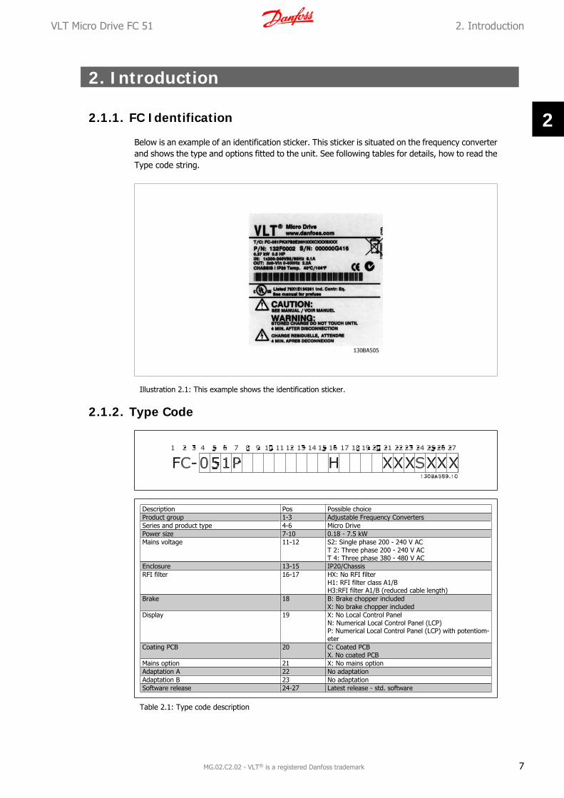
Below is an example of an identification sticker. This sticker is situated on the frequency converterand shows the type and options fitted to the unit. See following tables for details, how to read theType code string.
Illustration 2.1: This example shows the identification sticker.
2.1.2. Type Code
Description Pos Possible choiceProduct group 1-3 Adjustable Frequency ConvertersSeries and product type 4-6 Micro DrivePower size 7-10 0.18 - 7.5 kWMains voltage 11-12 S2: Single phase 200 - 240 V AC
T 2: Three phase 200 - 240 V ACT 4: Three phase 380 - 480 V AC
Enclosure 13-15 IP20/ChassisRFI filter 16-17 HX: No RFI filter
H1: RFI filter class A1/BH3:RFI filter A1/B (reduced cable length)
Brake 18 B: Brake chopper includedX: No brake chopper included
Display 19 X: No Local Control PanelN: Numerical Local Control Panel (LCP)P: Numerical Local Control Panel (LCP) with potentiom-eter
Coating PCB 20 C: Coated PCBX. No coated PCB
Mains option 21 X: No mains optionAdaptation A 22 No adaptationAdaptation B 23 No adaptationSoftware release 24-27 Latest release - std. software
Table 2.1: Type code description
VLT Micro Drive FC 51 2. Introduction
MG.02.C2.02 - VLT® is a registered Danfoss trademark 7
2
2.1.3. Symbols
Symbols used in this Programming Guide.
NB!Indicates something to be noted by the reader.
Indicates a general warning.
Indicates a high-voltage warning.
* Indicates default setting
2.1.4. Abbreviations and Standards
Terms: Abbreviations: SI-units: I-P units:Acceleration m/s² ft/s²American wire gauge AWG Automatic Motor Tuning AMT Current A AmpCurrent limit ILIM Energy J = N·m ft-lb, BtuFahrenheit ˚F Frequency Converter FC Frequency Hz HzKilohertz kHz Local Control Panel LCP Milliampere mA Millisecond ms Minute min Motion Control Tool MCT Motor Type Dependent M-TYPE Newton Metres Nm Nominal motor current IM,N Nominal motor frequency fM,N Nominal motor power PM,N Nominal motor voltage UM,N Parameter par. Protective Extra Low Voltage PELV Power W Btu/hr, hp
Pressure Pa = N/m² psi, psf, ft ofwater
Rated Inverter Output Current IINV Revolutions Per Minute RPM Size Related SR Temperature ˚C ˚FTime s s,hrTorque limit TLIM Voltage V V
Table 2.2: Abbreviation and Standards table .
2. Introduction VLT Micro Drive FC 51
8 MG.02.C2.02 - VLT® is a registered Danfoss trademark
2

3. Programming
3.1. How to Programme
3.1.1. Programming with MCT-10
The frequency converter can be programmed from a PC via RS485 com-port by installing theMCT-10 Set-up Software.
This software can either be ordered using code number 130B1000 or downloaded from the Dan-foss Web site: www.danfoss.com, Business Area: Motion Controls.
Please refer to manual MG.10.RX.YY.
3.1.2. Programming with LCP 11 or LCP 12
The LCP is divided into four functional groups:
1. Numeric display.
2. Menu key.
3. Navigation keys.
4. Operation keys and indicator lights (LEDs).
Illustration 3.1: LCP 12 with potentiometer Illustration 3.2: LCP 11 without potentiometer
The display:A number of information can be read from the display.
Set-up number shows the active set-up andthe edit set-up. If the same set-up acts asboth active and edit set-up, only that set-upnumber is shown (factory setting).When active and edit set-up differ, both num-bers are shown in the display (Setup 12). Thenumber flashing, indicates the edit set-up.
Illustration 3.3: Indicating Set-up
VLT Micro Drive FC 51 3. Programming
MG.02.C2.02 - VLT® is a registered Danfoss trademark 9
3
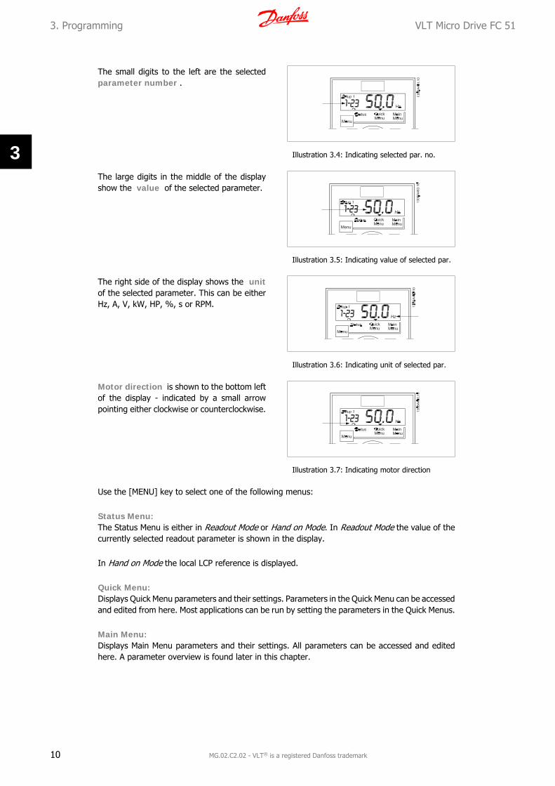
The small digits to the left are the selectedparameter number .
Illustration 3.4: Indicating selected par. no.
The large digits in the middle of the displayshow the value of the selected parameter.
Illustration 3.5: Indicating value of selected par.
The right side of the display shows the unitof the selected parameter. This can be eitherHz, A, V, kW, HP, %, s or RPM.
Illustration 3.6: Indicating unit of selected par.
Motor direction is shown to the bottom leftof the display - indicated by a small arrowpointing either clockwise or counterclockwise.
Illustration 3.7: Indicating motor direction
Use the [MENU] key to select one of the following menus:
Status Menu:The Status Menu is either in Readout Mode or Hand on Mode. In Readout Mode the value of thecurrently selected readout parameter is shown in the display.
In Hand on Mode the local LCP reference is displayed.
Quick Menu:Displays Quick Menu parameters and their settings. Parameters in the Quick Menu can be accessedand edited from here. Most applications can be run by setting the parameters in the Quick Menus.
Main Menu:Displays Main Menu parameters and their settings. All parameters can be accessed and editedhere. A parameter overview is found later in this chapter.
3. Programming VLT Micro Drive FC 51
10 MG.02.C2.02 - VLT® is a registered Danfoss trademark
3

Indicator lights:• Green LED: Power is on the frequency converter.
• Yellow LED: Indicates a warning.
• Flashing red LED: Indicates an alarm.
Navigation Keys:[Back]: For moving to the previous step or layer in the navigation structure.Arrows [] []: For manoeuvring between parameter groups, parameters and within parame-ters.[OK]: For selecting a parameter and for accepting changes to parameter settings.
Operation Keys:A yellow light above the operation keys indicates the active key.[Hand on]: Starts the motor and enables control of the frequency converter via the LCP.[Off/Reset]: The motor stops except in alarm mode. In that case the motor will be reset.[Auto on]: The frequency converter is controlled either via control terminals or serial communi-cation.[Potentiometer] (LCP12): The potentiometer works in two ways depending on the mode inwhich the frequency converter is running.In Auto Mode the potentiometer acts as an extra programmable analog input.In Hand on Mode the potentiometer controls local reference.
3.2. Status Menu
After power up the Status Menu is active. Usethe [MENU] key to toggle between Status,Quick Menu and Main Menu.
Arrows [] and [] toggles between thechoices in each menu.
The display indicates the status mode with asmall arrow above “Status”.
Illustration 3.8: Indicating Status mode
3.3. Quick Menu
The Quick Menu gives easy access to the most frequently used parameters.
1. To enter the Quick Menu, press[MENU] key until indicator in displayis placed above Quick Menu, thenpress [OK].
2. Use [] [] to browse through theparameters in the Quick Menu.
3. Press [OK] to select a parameter.
4. Use [] [] to change the value of aparameter setting.
5. Press [OK] to accept the change.
6. To exit, press either [Back] twice toenter Status, or press [Menu] onceto enter Main Menu.
Illustration 3.9: Indicating Quick Menu mode
VLT Micro Drive FC 51 3. Programming
MG.02.C2.02 - VLT® is a registered Danfoss trademark 11
3

3.4. Main Menu
The Main Menu gives access to all parameters.
1. To enter the Main Menu, press[MENU] key until indicator in displayis placed above Main Menu.
2. Use [] [] to browse through theparameter groups.
3. Press [OK] to select a parametergroup.
4. Use [] [] to browse through theparameters in the specific group.
5. Press [OK] to select the parameter.
6. Use [] [] to set/change the pa-rameter value.
7. Press [OK] to accept the value.
8. To exit, press either [Back] twice toenter Quick Menu, or press [Menu]once to enter Status.
Illustration 3.10: Indicating Main Menu mode
3. Programming VLT Micro Drive FC 51
12 MG.02.C2.02 - VLT® is a registered Danfoss trademark
3
4. Parameter Descriptions
4.1. Parameter group 0: Operation/Display
0-03 Regional Settings
Option: Function:
In order to meet the needs for different default settings in dif-ferent parts of the world, par. 0-03, Regional Settings, is imple-mented in the frequency converter. The selected settinginfluences the default setting of the motor nominal frequency.
[0 ] * International Sets default of par. 1-23, Motor Frequency, to 50 Hz.
[1] US Sets default of par. 1-23, Motor Frequency, to 60 Hz.
NB!This parameter cannot be adjusted while motorruns.
0-04 Operating State at Power-up (Hand Mode)
Option: Function:
This parameter controls whether or not the frequency convertershould start running the motor when powering up after a powerdown in Hand mode.
NB!If LCP with potmeter is mounted, reference is setaccording to actual potmeter value.
[0] Resume Frequency converter starts in same Hand or Off State as whenpowered off.
Local reference is stored and used after power-up.
[1] * Forced Stop, Ref=Old Frequency converter powers up in Off State meaning that motoris stopped after power up.
Local reference is stored and used after power-up.
[2] Forced Stop, Ref=0 Frequency converter powers up in Off State meaning that motoris stopped after power up.
Local reference is set to 0. Thus motor will not start runningbefore local reference has been increased.
4.1.1. 0-1* Set-up Handling
User defined parameters and miscellaneous external inputs (eg. bus, LCP, analog/digital inputs,feedback, etc.) controls the functionality of the frequency converter.
A complete set of all parameters controlling the frequency converter is called a set-up. The MicroDrive FC 51 contains 2 set-ups, Set-up1 and Set-up 2.
VLT Micro Drive FC 51 4. Parameter Descriptions
MG.02.C2.02 - VLT® is a registered Danfoss trademark 13
4
Furthermore, a fixed set of factory settings can be copied into one or more set-ups.
Some of the advantages of having more than one set-up in the frequency converter are
• Run motor in one set-up (Active Set-up) while updating parameters in another set-up(Edit Set-up)
• Connect various motors (one at a time) to frequency converter. Motor data for variousmotors can be placed in different set-ups.
• Rapidly change settings of frequency converter and/or motor while motor is running (eg.ramp time or preset references) via bus or digital inputs.
The Active Set-up can be set as Multi Set-up where the active set-up is selected via input on adigital input terminal and/or via the bus control word.
NB!FactorySet-up cannot be used as Active Set-up.
0-10 Active Set-up
Option: Function:
Active Set-up controls the motor.Shifts between set-ups can only happen when
• the motor is coasted
OR
• the set-ups between which the shift happens are linkedto each other (see par. 0-12, Linked Set-ups).
If changing between set-ups that are not linked, the change willnot happen before motor is coasted.
NB!The motor is only considered stopped when it iscoasted.
[1 ] * Set-up 1 Set-up 1 is active.
[2] Set-up 2 Set-up 2 is active.
[9] Multi Set-up Select the active set-up via digital input and/or bus, see par.5-1* choice [23].
0-11 Edit Set-up
Option: Function:
The Edit Set-up is for updating parameters in the frequencyconverter from either LCP or bus. It can be identical or differentfrom the Active Set-up.
All set-ups can be edited during operation, independently of theactive set-up.
[1 ] * Set-up 1 Update parameters in Set-up 1.
[2] Set-up 2 Update parameters in Set-up 2.
4. Parameter Descriptions VLT Micro Drive FC 51
14 MG.02.C2.02 - VLT® is a registered Danfoss trademark
4

[9] Active Set-up Update parameters in set-up selected as Active Set-up (see par.0-10).
0-12 Link Set-ups
Option: Function:
The link ensures synchronizing of the “not changeable duringoperation” parameter values enabling shift from one set-up toanother during operation.
If the set-ups are not linked, a change between them is notpossible while the motor is running. Thus the set-up changedoes not occur until the motor is coasted.
[0] Not linked Leaves parameters unchanged in both set-ups and cannot bechanged while motor runs.
[1 ] * Linked Copy parameters “not changeable during operation” parametervalues into presently selected Edit Set-up.
NB!This parameter cannot be changed while motorruns.
4.1.2. 0-4* LCP Keypad
The frequency converter can operate in the following three modes: Hand, Off and Auto.Hand: The frequency converter is locally operated and does not allow any remote control. Byactivating Hand a start signal is given.OFF: The frequency converter stops with a normal stop ramp. When Off is chosen the frequencyconverter can only be started by pressing either Hand or Auto on the LCP.Auto: In Auto-mode the frequency converter can be remote controlled (bus/digital).
0-40 [Hand on] Key on LCP
Option: Function:
[0] Disabled Hand-on key has no function.
[1 ] * Enabled Hand-on key is functional.
0-41 [Off/Reset] Key on LCP
Option: Function:
[0] Disable Off/Reset Off/reset key has no function.
[1 ] * Enable Off/Reset Stop signal and reset of any faults.
[2] Enable Reset Only Reset only. Stop (Off) function is disabled.
0-42 [Auto on] Key on LCP
Option: Function:
[0] Disabled Auto-on key has no function.
[1 ] * Enabled Auto-on key is functional.
VLT Micro Drive FC 51 4. Parameter Descriptions
MG.02.C2.02 - VLT® is a registered Danfoss trademark 15
4
4.1.3. 0-5* Copy/Save
0-50 LCP Copy
Option: Function:
The detachable LCP of the frequency converter can be used forstoring setups, and thus for transferring data when moving pa-rameter settings from one frequency converter to another.
NB!LCP Copy can only be activated from the LCP andONLY when the motor is coasted.
[1] All to LCP Copy all setups from the frequency converter into the LCP.
[2] All from LCP Copy all setups from LCP to frequency converter.
[3] Size indep. from LCP Copy non motor size dependent data from LCP to frequencyconverter
0-51 Set-up Copy
Option: Function:
Use this function to copy a set-up content into the Edit Set-up.In order to be able to make a set-up copy ensure that
• the motor is coasted
• par. 0-10, Active Set-up, is set to either Set-up 1 [1]or Set-up 2 [2]
NB!The keyboard/parameter database are blockedwhile Set-up Copy is running.
[0 ] * No Copy Copy function is inactive
[1] Copy from Set-up 1 Copy from Set-up 1 to edit set-up chosen in par. 0-11, Edit Set-up.
[2] Copy from Set-up 2 Copy from Set-up 2 to edit set-up chosen in par. 0-11, Edit Set-up.
[9] Copy from FactorySet-up
Copy from Factory Settings to edit set-up chosen in par. 0-11,Edit set-up.
4.1.4. 0-6* Password
0-60 (Main) Menu Password
Range: Function:
Use password for protection against unintended change of sen-sitive parameters, eg. motor parameters.
Password protected parameters can always be read, but cannotbe edited without entering the password.
4. Parameter Descriptions VLT Micro Drive FC 51
16 MG.02.C2.02 - VLT® is a registered Danfoss trademark
4

0 * [0 - 999] Enter the password for access to Main Menu via the [Main Menu]key. Select the number that should allow for changing otherparameter values. 0 means there is no password.
NB!A password only has affect on the LCP - not on the bus communication.
VLT Micro Drive FC 51 4. Parameter Descriptions
MG.02.C2.02 - VLT® is a registered Danfoss trademark 17
4

4.2. Parameter Group 1: Load/Motor
1-00 Configuration Mode
Option: Function:
Use this parameter for selecting the application control principleto be used when a Remote Reference is active.
NB!Changing this parameter will reset parameters3-00, 3-02 and 3-03 to their default values.
NB!This parameter cannot be adjusted while motorruns.
[0 ] * Speed Open Loop For normal speed control (References).
[3] Process Closed Loop Enables process closed loop control. See par. group 7-3* forfurther information on PI-controller.
When running in process closed loop, par. 4-10 Motor SpeedDirection must be set to Clockwise [0]
1-01 Motor Control Principle
Option: Function:
[0] U/f Is used for parallel connected motors and/or special motor ap-plications. The U/f settings are set in parameters 1-55 and 1-56.
NB!When running U/f control slip- and load compen-sations are not included.
[1] * VVC+ Normal running mode, including slip- and load compensations.
1-03 Torque Characteristics
Option: Function:
With more torque characteristics it is possible to run low energyconsuming, as well as high torque applications.
[0 ] * Constant Torque Motor shaft output provides constant torque under variablespeed control.
[2] Automatic Energy Op-tim.
This function automatically optimizes energy consumption incentrifugal pump and fan applications. See par. 14-41 AEO Min-imum Magnetisation.
4. Parameter Descriptions VLT Micro Drive FC 51
18 MG.02.C2.02 - VLT® is a registered Danfoss trademark
4

1-05 Hand Mode Configuration
Option: Function:
This parameter is only relevant when parameter 1-00 Configu-ration Mode is set to Process Closed Loop [3]. The parameter isused for determining the reference or setpoint handling whenchanging from Auto Mode to Hand Mode on the LCP.
[0] Speed Open Loop In Hand Mode the drive always runs in Open Loop configurationregardless of setting in par. 1-00 Configuration Mode. Local po-tentiometer (if present) or Arrow up/down determines outputfrequency limited by Motor Speed High/Low Limit (parameters4-14 and 4-12).
[2] * As configuration inpar. 1-00
If par. 1-00 Configuration Mode is set to Open Loop [1] functionis as described above.If par. 1-00 is set to Process Closed Loop [3] changing from Automode to Hand mode results in a setpoint change via local po-tentiometer or Arrow up/down. The change is limited by Refer-ence Max/Min (parameters 3-02 and 3-03).
4.2.1. 1-2* Motor Data
Enter the correct motor nameplate data (power, voltage, frequency, current and speed).Run AMT, see par. 1-29.Factory settings for advanced motor data, par. 1-3*, are automatically calculated.
NB!Parameters in parameter group 1.2* cannot be adjusted while motor runs.
1-20 Motor Power [kW]/[HP] (Pm.n)
Range: Function:
Enter motor power from nameplate data.
[0.09 kW/0.12 HP -11 kW/15 HP]
Two sizes down, one size up from nominal VLT rating.
NB!Changing this parameter affects par. 1-22 to 1-25,1-30, 1-33 and 1-35.
1-22 Motor Voltage (U m.n)
Range: Function:
230/400V
[50 - 999 V] Enter motor voltage from nameplate data.
1-23 Motor Frequency (f m.n)
Range: Function:
50 Hz* [20-400 Hz] Enter motor frequency from nameplate data.
VLT Micro Drive FC 51 4. Parameter Descriptions
MG.02.C2.02 - VLT® is a registered Danfoss trademark 19
4

1-24 Motor Current (I m.n)
Range: Function:
M-typedepend-ent*
[0.01 - 26.00 A] Enter motor current from nameplate data.
1-25 Motor Nominal Speed (n m.n)
Range: Function:
M-typeDepend-ent*
[100 - 9999 RPM] Enter motor nominal speed from nameplate data.
1-29 Automatic Motor Tuning (AMT)
Option: Function:
Use AMT to optimize motor performance.
NB!This parameter cannot be changed while motorruns.
1. Stop VLT – make sure motor is at standstill
2. Choose [2] Enable AMT
3. Apply start signal– Via LCP: Press Hand On- Or in Remote On mode: Apply start signal on terminal18
[0] * Off AMT function is disabled.
[2] Enable AMT AMT function starts running.
NB!To gain optimum tuning of frequency converter,run AMT on a cold motor.
4.2.2. 1-3* Adv. Motor Data
Adjust advanced motor data using one of these methods:
1. Run AMT on cold motor. Frequency converter measures value from motor.
2. Enter X1 value manually. Obtain value from motor supplier.
3. Use X1 default setting. Frequency converter establishes setting based on motor name-plate data.
NB!This parameter cannot be changed while motor runs.
4. Parameter Descriptions VLT Micro Drive FC 51
20 MG.02.C2.02 - VLT® is a registered Danfoss trademark
4
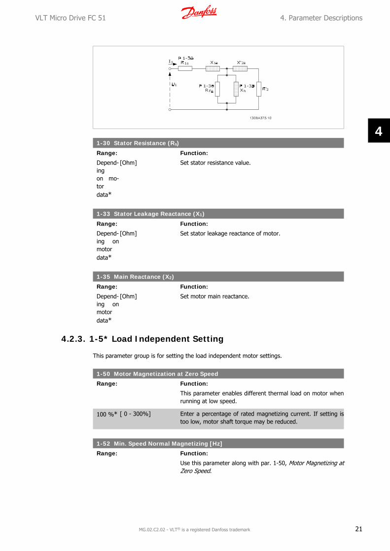
1-30 Stator Resistance (Rs)
Range: Function:
Depend-ingon mo-tordata*
[Ohm] Set stator resistance value.
1-33 Stator Leakage Reactance (X1)
Range: Function:
Depend-ing onmotordata*
[Ohm] Set stator leakage reactance of motor.
1-35 Main Reactance (X2)
Range: Function:
Depend-ing onmotordata*
[Ohm] Set motor main reactance.
4.2.3. 1-5* Load Independent Setting
This parameter group is for setting the load independent motor settings.
1-50 Motor Magnetization at Zero Speed
Range: Function:
This parameter enables different thermal load on motor whenrunning at low speed.
100 %* [ 0 - 300%] Enter a percentage of rated magnetizing current. If setting istoo low, motor shaft torque may be reduced.
1-52 Min. Speed Normal Magnetizing [Hz]
Range: Function:
Use this parameter along with par. 1-50, Motor Magnetizing atZero Speed.
VLT Micro Drive FC 51 4. Parameter Descriptions
MG.02.C2.02 - VLT® is a registered Danfoss trademark 21
4

0.0 Hz* [0.0 - 10.0 Hz] Set frequency required for normal magnetizing current. If fre-quency is set lower than motor slip frequency, par. 1-50, MotorMagnetizing at Zero Speed is inactive.
1-55 U/f Characteristic - U
Range: Function:
This parameter is an array parameter [0-5] and is only func-tional when par. 1-01, Motor Control Principle is set to U/f [0].
0.0 V* [0.0 - 999.9 V] Enter voltage at each frequency point to manually form a U/fcharacteristic matching motor. Frequency points are defined inpar. 1-56, U/f characteristics - F.
1-56 U/f Characteristic - F
Range: Function:
This parameter is an array parameter [0-5] and is only func-tional when par. 1-01, Motor Control Principle is set to U/f [0].
0.0 Hz* [0.0 - 1000.0 Hz] Enter frequency points to manually form a U/f characteristicmatching motor. Voltage at each point is defined in par. 1-55,U/f Characteristic - U.
Make a U/f characteristic based on 6 definable voltages and fre-quencies, see below figure.Simplify U/f characteristics by merging 2 or more points (vol-tages and frequencies), respectively, are set equal.
Illustration 4.1: Fig. 1 U/f characteristics
NB!For par. 1-56 the following applies[0] ≦ [1] ≦ [2] ≦ [3] ≦ [4] ≦ [5]
4. Parameter Descriptions VLT Micro Drive FC 51
22 MG.02.C2.02 - VLT® is a registered Danfoss trademark
4

4.2.4. 1-6* Load Dependent setting
Parameters for adjusting the load dependent motor settings.
1-60 Low Speed Load Compensation
Range: Function:
Use this parameter to gain optimum U/f characteristic whenrunning at low speed.
100 %* [0-199 %] Enter percentage in relation to load when motor runs at lowspeed.
Change-over point is automatically calculated based on motorsize.
1-61 High Speed Load Compensation
Range: Function:
Use this parameter to obtain optimum load compensation whenrunning at high speed.
100 %* [0 - 199 %] Enter percentage to compensate in relation to load when motorruns at high speed.
Change-over point is automatically calculated based on motorsize.
1-62 Slip Compensation
Range: Function:
100 %* [-400 - 399 %] Compensation for load dependent motor slip.Slip compensation is calculated automatically based on ratedmotor speed, nM,N.
NB!This function is only active when par. 1-00, Con-figuration Mode, is set to Speed Open Loop [0],and when par. 1-01, Motor Control Principle, is setto VVC+ [1].
VLT Micro Drive FC 51 4. Parameter Descriptions
MG.02.C2.02 - VLT® is a registered Danfoss trademark 23
4
1-63 Slip Compensation Time
Range: Function:
0.10 s [0.05 - 5.00 s] Enter slip compensation reaction speed. A high value results inslow reaction whereas a low value results in quick reaction.
If low-frequency resonance problems arise, use longer time set-ting.
4.2.5. 1-7* Start Adjustments
Considering the need for various start functions in different applications, it is possible to select anumber of functions in this parameter group.
1-71 Start Delay
Range: Function:
The start delay defines the time to pass from a start commandis given until the motor starts accelerating.Setting start delay to 0.0 sec. disables Start Function, [1-72],when start command is given.
0.0 s* [0.0 - 10.0 s] Enter the time delay required before commencing acceleration.Par. 1-72 Start Function is active during Start delay time .
1-72 Start Function
Option: Function:
[0] DC Hold/Delay Time Motor is energized with DC holding current (par. 2-00) duringstart delay time.
[1] DC Brake/Delay Time Motor is energized with DC braking current (par. 2-01) duringstart delay time.
[2] * Coast/Delay Time Inverter is coasted during start delay time (inverter off).
1-73 Flying Start
Option: Function:
Use flying start to catch a spinning motor after eg. mains drop-out.
This function is not suitable for hoisting applica-tions.
[0] * Disabled Flying start is not required.
[1] Enabled Frequency converter enabled to catch spinning motor.
NB!When flying start is enabled par. 1-71, Start De-lay, and par. 1-72, Start Function, have no func-tion.
4. Parameter Descriptions VLT Micro Drive FC 51
24 MG.02.C2.02 - VLT® is a registered Danfoss trademark
4
4.2.6. 1-8* Stop Adjustments
To meet the need for various stop functions in different application these parameters offer somespecial stop features for the motor.
1-80 Function at Stop
Option: Function:
The selected function at stop is active in following situations:
• Stop command is given and output speed is rampeddown to Min. Speed for Activating Functions at Stop.
• Start command is removed (standby), and outputspeed is ramped down to Min. Speed for ActivatingFunctions at Stop.
• DC-brake command is given, and DC-brake time haspassed
• While running and calculated output speed is belowMin. Speed for Activating Functions at Stop.
[0] * Coast The inverter is coasted.
[1] DC hold The motor is energized with a DC current. See par. 2-00 DC HoldCurrent for more information.
1-82 Min. Speed For Function at Stop [Hz]
Range: Function:
0.0 Hz* [0.0 - 20.0 Hz] Set the speed at which to activate par. 1-80 Function at Stop.
4.2.7. 1-9* Motor Temperature
With an estimated motor temperature monitor the frequency converter is able to estimate motortemperature without having a thermistor mounted. It is thus possible to receive a warning or analarm, if motor temperature exceeds upper operational limit.
1-90 Motor Thermal Protection
Option: Function:
Using ETR (Electronic Terminal Relay) the motor temperature iscalculated based on frequency, speed and time. Danfoss rec-ommends using The ETR function, if a thermistor is not present.
NB!ETR calculation is based on motor data from group1-2*.
[0] * No Protection Disables temperature monitoring.
[1] Thermistor Warning A thermistor connected to either digital or analog input gives awarning if upper limit of motor temperature range is exceeded,(see par. 1-93, Thermistor Resource).
VLT Micro Drive FC 51 4. Parameter Descriptions
MG.02.C2.02 - VLT® is a registered Danfoss trademark 25
4
[2] Thermistor Trip A thermistor connected to either digital or analog input gives analarm and makes the frequency converter trip if upper limit ofmotor temperature range is exceeded, (see par. 1-93, Thermis-tor Resource.
[3] ETR Warning If calculated upper limit of motor temperature range is excee-ded, a warning occurs.
[4] ETR Trip If calculated upper limit of motor temperature range is excee-ded, an alarm occurs and frequency converter trips.
1-93 Thermistor Resource
Option: Function:
Select the thermistor input terminal.
[0] * None No thermistor is connected.
[1] Analog Input 53 Connect thermistor to analog input terminal 53.
NB!Analog input 53 cannot be selected for other pur-poses when selected as thermistor resource.
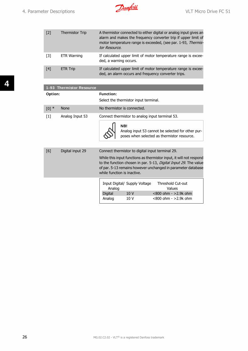
[6] Digital input 29 Connect thermistor to digital input terminal 29.
While this input functions as thermistor input, it will not respondto the function chosen in par. 5-13, Digital Input 29. The valueof par. 5-13 remains however unchanged in parameter databasewhile function is inactive.
Input Digital/Analog
Supply Voltage Threshold Cut-outValues
Digital 10 V <800 ohm - >2.9k ohmAnalog 10 V <800 ohm - >2.9k ohm
4. Parameter Descriptions VLT Micro Drive FC 51
26 MG.02.C2.02 - VLT® is a registered Danfoss trademark
4
4.3. Parameter Group 2: Brakes
4.3.1. 2-** Brakes
4.3.2. 2-0* DC-Brake
The purpose of DC-brake function is to brake a rotating motor by applying DC-current to the motor.
2-00 DC Hold Current
Range: Function:
This parameter either holds the motor (holding torque) or pre-heats the motor.The parameter is active if DC Hold has been selected in eitherpar. 1-72 Start Function or par. 1-80 Function at Stop.
50%* [0 - 100%] Enter a value for holding current as a percentage of the ratedmotor current set in par. 1-24 Motor Current. 100% DC holdingcurrent corresponds to IM,N.
NB!Avoid 100% current too long as it may overheat the motor.
2-01 DC Brake Current
Range: Function:
50 %* [0 - 150%] Set DC-current needed to brake rotating motor.
Activate DC-brake in one of the four following ways:
1. DC-brake command, see par. 5-1* choice [5]
2. DC Cut-in function, see par. 2-04
3. DC-brake selected as start function, see par. 1-72
4. DC-brake in connection with Flying Start, par. 1-73.
2-02 DC-Braking Time
Range: Function:
DC-braking time defines the period during which DC-brake cur-rent is applied to the motor.
10.0 s* [0.0 - 60 s] Set the time DC-braking current, set in par. 2-01, must be ap-plied.
NB!If DC-brake is activated as start function, DC-brake time is defined by start delaytime.
VLT Micro Drive FC 51 4. Parameter Descriptions
MG.02.C2.02 - VLT® is a registered Danfoss trademark 27
4

2-04 DC-Brake Cut-in Speed
Range: Function:
0.0 Hz* [0.0 - 400.0 Hz] Set DC-brake cut-in speed to activate DC braking current, set inpar. 2-01, when ramping down.When set to 0 the function is off.
4.3.3. 2-1* Brake Energy Function
Use the parameters in this group for selecting dynamic braking parameters.
2-10 Brake Function
Option: Function:
Resistor Brake:The resistor brake limits voltage in the intermediate circuit whenthe motor acts as generator. Without brake resistor, the fre-quency converter eventually trips.
The resistor brake consumes surplus energy resulting from mo-tor braking. A frequency converter with brake stops a motorfaster than without a brake, which is used in many applications.Requires connection of external brake resistor.
An alternative to the resistor brake is the AC brake.
NB!Resistor brake is only functional in frequency con-verters with integrated dynamic brake. An exter-nal resistor must be connected.
AC Brake:The AC brake consumes surplus energy by creating power lossin the motor.It is important to keep in mind that an increase in power losscauses motor temperature to rise.
[0] * Off No brake function.
[1] Resistor Brake Resistor brake is active.
[2] AC Brake AC brake is active.
2-11 Brake Resistor (Ohm)
Range: Function:
5 Ω* [5 - 5000 Ω] Set brake resistor value.
2-16 AC Brake, Max Current
Range: Function:
100.0 %*
[0.0 - 150.0 %] Enter max. permissible current for AC-braking to avoid over-heating of motor.
100% equals motor current set in par. 1-24.
4. Parameter Descriptions VLT Micro Drive FC 51
28 MG.02.C2.02 - VLT® is a registered Danfoss trademark
4

2-17 Over-Voltage Control
Option: Function:
Use Over-voltage Control (OVC) to reduce the risk of the fre-quency converter tripping due to an over voltage on the DC linkcaused by generative power from the load.An over-voltage occurs eg. if the ramp down time is set too shortcompared to the actual load inertia.
[0] * Disabled The OVC is not active/required.
[1] Enabled, not at stop OVC is running unless a stop signal is active.
[2] Enabled OVC is running, also when a stop signal is active.
NB!If Resistor Brake has been chosen in par. 2-10 Brake Function the OVC is not activeeven though enabled in this parameter.
4.3.4. 2-2* Mechanical Brake
For hoisting applications an electro-magnetic brake is required. The brake is controlled by a relay,which releases the brake when activated.
The brake activates if frequency converter trips or a coast command is given. Furthermore, itactivates when motor speed is ramped down below the speed set in par. 2-22, Active BrakeSpeed.
2-20 Release Brake Current
Range: Function:
0.00 A* [0.00 - 100 A] Select motor current at which mechanical brake releases.
If start delay time has passed, and motor currentis below Release brake current, frequency con-verter trips.
2-22 Activating Mechanical Brake
Range: Function:
If the motor is stopped using ramp, the mechanical brake is ac-tivated when motor speed is less than Active Brake Speed.Motor is ramped down to stop in the following situations:
• A start command is removed (stand by)
• A stop command is activated
• Quick-stop is activated (Q-stop ramp is used)
0 Hz* [0 - 400 Hz] Select motor speed at which mechanical brake activates whenramping down.
Mechanical brake automatically activates if frequency convertertrips or reports an alarm.
VLT Micro Drive FC 51 4. Parameter Descriptions
MG.02.C2.02 - VLT® is a registered Danfoss trademark 29
4

4.4. Parameter Group 3: Reference/Ramps
4.4.1. 3-** Reference/Ramps
Parameters for reference handling, definition of limitations, and configuration of the frequencyconverter's reaction to changes
4.4.2. 3-0* Reference Limits
Parameters for setting the reference unit, limits and ranges.
3-00 Reference Range
Option: Function:
Select the range of reference and feedback signals. Values canbe both positive and negative, unless par. 1-00, ConfigurationMode, is set to Process Closed Loop [3]. In that case only pos-itive values are allowed.
[0] * Min - Max Reference setpoint ranges can have positive values only.Select this if running in Process Closed Loop.
[1] -Max - +Max Ranges can have both positive and negative values.
3-02 Minimum Reference
Range: Function:
0.00* [-4999 - 4999] Enter value for minimum reference.
The sum of all internal and external references are clamped(limited) to the minimum reference value, par. 3-02.
3-03 Maximum Reference
Range: Function:
Maximum Reference is adjustable in the range Minimum Refer-ence - 4999.
50.00* [-4999 - 4999] Enter value for Maximum Reference.
The sum of all internal and external references are clamped(limited) to the maximum reference value, par. 3-03.
4.4.3. 3-1* References
Parameters for setting up the reference sources. Select the preset references for the correspond-ing digital inputs in parameter group 5.1*, Digital Inputs.
3-10* Preset Reference
Option: Function:
Each parameter set-up contains 8 preset references which areselectable via 3 digital inputs or bus.
4. Parameter Descriptions VLT Micro Drive FC 51
30 MG.02.C2.02 - VLT® is a registered Danfoss trademark
4
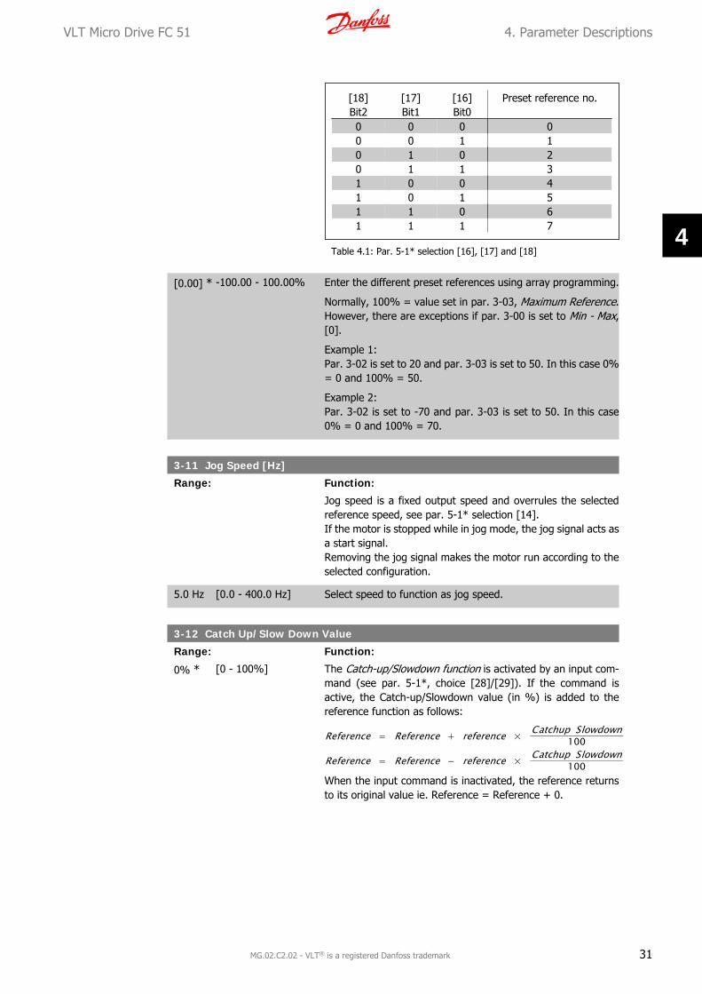
[18]Bit2
[17]Bit1
[16]Bit0
Preset reference no.
0 0 0 00 0 1 10 1 0 20 1 1 31 0 0 41 0 1 51 1 0 61 1 1 7
Table 4.1: Par. 5-1* selection [16], [17] and [18]
[0.00] * -100.00 - 100.00% Enter the different preset references using array programming.
Normally, 100% = value set in par. 3-03, Maximum Reference.However, there are exceptions if par. 3-00 is set to Min - Max,[0].
Example 1:Par. 3-02 is set to 20 and par. 3-03 is set to 50. In this case 0%= 0 and 100% = 50.
Example 2:Par. 3-02 is set to -70 and par. 3-03 is set to 50. In this case0% = 0 and 100% = 70.
3-11 Jog Speed [Hz]
Range: Function:
Jog speed is a fixed output speed and overrules the selectedreference speed, see par. 5-1* selection [14].If the motor is stopped while in jog mode, the jog signal acts asa start signal.Removing the jog signal makes the motor run according to theselected configuration.
5.0 Hz [0.0 - 400.0 Hz] Select speed to function as jog speed.
3-12 Catch Up/Slow Down Value
Range: Function:
0% * [0 - 100%] The Catch-up/Slowdown function is activated by an input com-mand (see par. 5-1*, choice [28]/[29]). If the command isactive, the Catch-up/Slowdown value (in %) is added to thereference function as follows:
Reference = Reference + reference × Catchup Slowdown100
Reference = Reference − reference × Catchup Slowdown100
When the input command is inactivated, the reference returnsto its original value ie. Reference = Reference + 0.
VLT Micro Drive FC 51 4. Parameter Descriptions
MG.02.C2.02 - VLT® is a registered Danfoss trademark 31
4

3-14 Preset Relative Reference
Range: Function:
0.00% [-100.00 - 100.00%] Define fixed value in % to be added to variable value defined inpar. 3-18, Relative Scaling Reference Source.
The sum of fixed and variable values (labelled Y in illustrationbelow) is multiplied with actual reference (labelled X in illusta-tion). This product is added to actual reference
X + X × Y100
3-15 Reference 1 Source
Option: Function:
Par. 3-15, 3-16 and 3-17 define up to three different referencesignals. The sum of these reference signals defines the actualreference.
[0] No Function No reference signal is defined.
[1] * Analog Input 53 Use signals from analog input 53 as reference, see par. 6-1*.
[2] Analog Input 60 Use signals from analog input 60 as reference, see par. 6-2*.
[11] Local Bus Ref. Use signals from local bus as reference, see par. 8-9*.
[21] LCP Potentiometer Use signals from LCP potentiometer as reference, see par. 6-8*.
[8] Pulse input Use signals from pulse input as reference, see par. 5-5*.
3-16 Reference 2 Source
Option: Function:
See Par. 3-15 for description.
[0] No Function No reference signal is defined.
[1] Analog Input 53 Use signals from analog input 53 as reference.
[2] * Analog Input 60 Use signals from analog input 60 as reference.
[11] Local Bus Ref. Use signals from local bus as reference.
[21] LCP Potentiometer Use signals from LCP potentiometer as reference.
3-17 Reference 3 Source
Option: Function:
See Par. 3-15 for description.
[0] No Function No reference signal is defined.
[1] Analog Input 53 Use signals from analog input 53 as reference.
4. Parameter Descriptions VLT Micro Drive FC 51
32 MG.02.C2.02 - VLT® is a registered Danfoss trademark
4
[2] Analog Input 60 Use signals from analog input 60 as reference.
[11] * Local Bus Ref. Use signals from local bus as reference.
[21] LCP Potentiometer Use signals from LCP potentiometer as reference.
3-18 Relative Scaling Reference Source
Option: Function:
Select the source for a variable value to be added to the fixedvalue defined in par. 3-14, Preset Relative Reference.
[0] * No Function The function is disabled
[1] Analog Input 53 Select analog input 53 as relative scaling reference source.
[2] Analog Input 54 Select analog input 54 as relative scaling reference source.
[8] Pulse Input 33 Select pulse input 33 as relative scaling reference source.
[11] Local Bus Ref. Select local bus ref. as relative scaling reference source.
[21] LCP Potentiometer Select LCP potentiometer as relative scaling reference source.
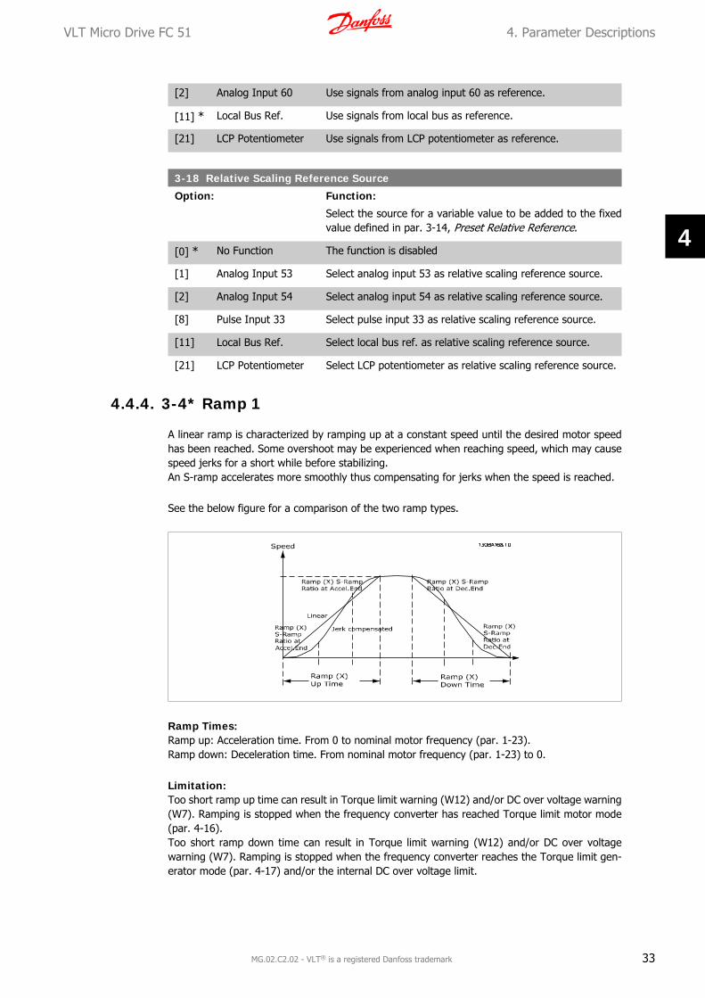
4.4.4. 3-4* Ramp 1
A linear ramp is characterized by ramping up at a constant speed until the desired motor speedhas been reached. Some overshoot may be experienced when reaching speed, which may causespeed jerks for a short while before stabilizing.An S-ramp accelerates more smoothly thus compensating for jerks when the speed is reached.
See the below figure for a comparison of the two ramp types.
Ramp Times:Ramp up: Acceleration time. From 0 to nominal motor frequency (par. 1-23).Ramp down: Deceleration time. From nominal motor frequency (par. 1-23) to 0.
Limitation:Too short ramp up time can result in Torque limit warning (W12) and/or DC over voltage warning(W7). Ramping is stopped when the frequency converter has reached Torque limit motor mode(par. 4-16).Too short ramp down time can result in Torque limit warning (W12) and/or DC over voltagewarning (W7). Ramping is stopped when the frequency converter reaches the Torque limit gen-erator mode (par. 4-17) and/or the internal DC over voltage limit.
VLT Micro Drive FC 51 4. Parameter Descriptions
MG.02.C2.02 - VLT® is a registered Danfoss trademark 33
4
3-40 Ramp1 Type
Option: Function:
[0] * Linear Constant acceleration/deceleration.
[2] S-ramp Smooth jerk compensated acceleration/deceleration.
3-41 Ramp1 Ramp-up Time
Range: Function:
3.00 s* [0.05 - 3600 s ] Enter ramp-up time from 0 Hz to rated motor frequency (fM,N)set in par. 1-23.Choose a ramp-up time ensuring that torque limit is not excee-ded, see par. 4-16.
3-42 Ramp1 Ramp-down Time
Range: Function:
3.00* [0.05 - 3600 s] Enter ramp down time from rated motor frequency (fM,N) in par.1-23 to 0 Hz.Choose a ramp down time that does not cause over-voltage ininverter due to regenerative operation of motor. Furthermore,regenerative torque must not exceed limit set in par. 4-17.
4.4.5. 3-5* Ramp2
See par. 3-4* for a description of ramp types.
NB!Ramp2 - alternative ramp times:Changing from Ramp1 to Ramp2 is done via the digital input. See par. 5-1*, selection[34].
3-50 Ramp2 Type
Option: Function:
[0] * Linear Constant acceleration/deceleration.
[2] S-ramp Smooth jerk compensated acceleration/deceleration.
3-51 Ramp2 Ramp-up Time
Range: Function:
3.000 * [0.100 - 3600 s] Enter ramp-up time from 0 Hz to rated motor frequency (fM,N)set in par. 1-23.Choose a ramp-up time ensuring that output current does notexceed current limit set in par. 4-18 during ramping.
3-52 Ramp2 Ramp-down Time
Range: Function:
3.000 s [0.100 - 3600 s] Enter ramp down time from rated motor frequency (fM,N) in par.1-23 to 0 Hz.
4. Parameter Descriptions VLT Micro Drive FC 51
34 MG.02.C2.02 - VLT® is a registered Danfoss trademark
4

Choose a ramp down time that does not cause over-voltage ininverter due to regenerative operation of motor. Furthermore,generated current must not exceed current limit set in par. 4-18.
4.4.6. 3-8* Other Ramps
This section contains parameters for Jog and Quick Stop Ramps.
With a Jog Ramp you can both ramp up and down whereas you can only ramp down with theQuick Stop Ramp.
3-80 Jog Ramp Time
Range: Function:
3.000 s* [0.100 - 3600 s] A linear ramp applicable when Jog is activated. See par. 5-1*,selection [14].Ramp up time = Ramp down time.
Jog Ramp time starts upon activation of a jog signal via a se-lected digital input or serial communication port.
3-81 Quick Stop Ramp Time
Range: Function:
3.000 s* [0.100 - 3600 s] A linear ramp applicable when Q-stop is activated. See par.5-1*, selection [4].
VLT Micro Drive FC 51 4. Parameter Descriptions
MG.02.C2.02 - VLT® is a registered Danfoss trademark 35
4
4.5. Parameter Group 4: Limits/Warnings
4.5.1. 4-** Motor Limits
Parameter group for configuring limits and warning.
4.5.2. 4-1* Motor Limits
Use these parameters for defining the speed, torque and current working range for the motor.
4-10 Motor Speed Direction
Option: Function:
If terminals 96, 97 and 98 are connected to U, V and W respec-tively, the motor runs clockwise when seen from the front.
NB!This parameter cannot be adjusted while the mo-tor is running
[0] Clockwise The motor shaft rotates in clockwise direction. This setting pre-vents the motor from running in counterclockwise direction.
If par. 1-00 Configuration mode has been set to Process ClosedLoop [3] this parameter must always be set to Clockwise.
[1] Counterclockwise The motor shaft rotates in counterclockwise direction. This set-ting prevents the motor from running in clockwise direction.
[2] * Both With this setting the motor can run in both directions. However,the output frequency is limited to the range: Motor Speed LowLimit (par. 4-12) to Motor Speed High Limit (par. 4-14).
4-12 Motor Speed Low Limit
Range: Function:
0.0 Hz* [0.0 - 400.0 Hz] Set the Minimum Motor Speed Limit corresponding to the min-imum output frequency of the motor shaft.
NB!As the minimum output frequency is an absolutevalue, it cannot be deviated from.
4-14 Motor Speed High Limit
Range: Function:
65.0Hz*
[0.0 - 400.0 Hz] Set the Maximum Motor Speed corresponding to the maximumoutput frequency of the motor shaft.
NB!As the maximum output frequency is an absolutevalue, it cannot be deviated from.
4. Parameter Descriptions VLT Micro Drive FC 51
36 MG.02.C2.02 - VLT® is a registered Danfoss trademark
4

4-16 Torque Limit in Motor Mode
Range: Function:
150.0 %*
[0.0 - 199.9%] Set the torque limit for motor operation.The setting is not automatically reset to default when changingsettings in par. 1-00 to 1-25 Load & Motor .
4-17 Torque Limit in Generator Mode
Range: Function:
150.0 %*
[0.0 - 199.9 %] Set the torque limit for generator mode operation.The setting is not automatically reset to default when changingsettings in par. 1-00 to 1-25 Load & Motor .
4.5.3. 4-5* Adjustable Warnings
Parameter group containing adjustable warning limits for current, speed, reference and feedback.
Warnings are shown in display, programmed output or serial bus.
4-50 Warning Current Low
Range: Function:
Use this parameter to set a lower limit for the current range.If current drops below the set limit, a warning occurs.
0.00 A [0.00 - 26.00 A] Set value for low current limit.
4-51 Warning Current High
Range: Function:
Use this parameter to set an upper limit for the current range.If current exceeds the set limit, a warning occurs.
26.00A*
[0.00 - 26.00 A] Set upper current limit.
4-58 Missing Motor Phase Function
Option: Function:
A missing motor phase causes the motor torque to drop. Thismonitor may be disabled for special purposes (eg. small motorsrunning pure U/f mode), but as there is a risk of overheating themotor, Danfoss strongly recommends that the function is On.
A missing motor phases causes the frequency converter to tripand report an alarm.
NB!This parameter cannot be changed while motorruns.
[0] Off Function is disabled.
[1] * On Function is enabled.
VLT Micro Drive FC 51 4. Parameter Descriptions
MG.02.C2.02 - VLT® is a registered Danfoss trademark 37
4

4.5.4. 4-6* Speed Bypass
In some applications mechanical resonance may occur. Avoid resonance points by creating a by-pass. The frequency converter ramps through the bypass area thereby passing mechanicalresonance points quickly.
4-61 Speed Bypass From [Hz]
Range: Function:
Array [2]
0.0 Hz* [0.0 - 400.0 Hz] Enter either the lower or upper limit of the speeds to be avoided.It does not matter whether Bypass From or Bypass Too is theupper or lower limit, however the Speed Bypass function is dis-abled if the two parameters are set to the same value.
4-63 Speed Bypass To [Hz]
Range: Function:
Array [2]
0.0 Hz* [0.0 - 400.0 Hz] Enter either the upper or lower limit of the speed area to beavoided.Make sure to enter the opposite limit of that in par. 4-61 SpeedBypass From [Hz].
4. Parameter Descriptions VLT Micro Drive FC 51
38 MG.02.C2.02 - VLT® is a registered Danfoss trademark
4

4.6. Parameter Group 5: Digital In/Out
4.6.1. 5-** Digital In/Out
The following describes all digital input command functions and signals.
4.6.2. 5-1* Digital Inputs
Parameters for configuring the functions for the input terminals.The digital inputs are used for selecting various functions in the frequency converter. All digitalinputs can be set to the following:
[0] No Operation The frequency converter will not react to signals transmitted tothe terminal.
[1] Reset Reset the frequency converter after a Trip/Alarm. Not all alarmscan be reset.
[2 ] Coast Inverse Coasting stop, inverted input (NC). The frequency converterleaves the motor in free mode.
[3] Coast and reset inv. Reset and coasting stop inverted input (NC). The frequencyconverter resets and leaves the motor in free mode.
[4] Quick stop inverse Inverted input (NC). Generates a stop in accordance with thequick-stop ramp time set in par. 3-81. When motor stops, shaftis in free mode.
[5] DC-brake inv. Inverted input for DC braking (NC). Stops motor by energizingit with DC current for a certain time period, see par. 2-01. Func-tion is only active when value in par. 2-02 is different from 0.
[6] Stop inv. Stop inverted function. Generates stop function when selectedterminal goes from logical level “1” to “0”. Stop is performedaccording to selected ramp time.
[8] Start Select start for a start/stop command.1 = Start, 0 = stop.
[9] Latched start Motor starts if a pulse is applied for min. 2 ms. Motor stops whenStop inverse is activated.
[10] Reversing Change direction of motor shaft rotation. Reversing signal onlychanges direction of rotation; it does not activate start function.Select Both directions [2] in par. 4.10.0 = normal, 1 = reversing.
[11] Start reversing Use for start/stop and for reversing at the same time. Signalson start [8] are not allowed at the same time.0 = stop, 1 = start reversing.
[12] Enable start forward Use if motor shaft must rotate clockwise at start.
[13] Enable start reverse Use if motor shaft must rotate counterclockwise at start.
[14] Jog Use for activating jog speed. See par. 3-11.
[16] Preset ref bit 0 Preset ref bit 0, 1 and 2 enables a choice between one of theeight preset references according to the table below.
VLT Micro Drive FC 51 4. Parameter Descriptions
MG.02.C2.02 - VLT® is a registered Danfoss trademark 39
4

[17] Preset ref bit 1 Same as preset ref bit 0 [16], see par. 3-10.
[18] Preset ref bit 2 Same as preset ref bit 0 [16].
[19] Freeze reference Freeze actual reference. The frozen reference is now the pointof enable/condition for Speed up and Speed down to be used.If Speed up/down is used, speed change always follows ramp 2(par. 3-51 and 3-52) in the range par. 3-02 Minimum Refer-ence - par. 3-03 Maximum Reference.
[20] Freeze output Freeze the actual motor frequency (Hz). The frozen motor fre-quency is now the point of enable/condition for Speed up andSpeed down to be used. If Speed up/down is used, the speedchange always follows ramp 2 in the range par. 4-12, MotorSpeed Low Limit - par. 4-14, Motor Speed High Limit.
NB!When freeze output is active, the frequency con-verter cannot be stopped via a low Start [8] signal.Stop the frequency converter via a terminal pro-grammed for Coasting Inverse [2] or Coast andreset, inverse [3].
[21] Speed up Select Speed up and Speed down if digital control of the up/down speed is desired (motor potentiometer). Activate thisfunction by selecting either Freeze reference or Freeze output.When Speed up is activated for less than 400 ms. the resultingreference will be increased by 0.1%. If Speed up is activated formore than 400 ms. the resulting reference will ramp accordingto ramp 2 in par. 3-51.
[22] Speed down Same as Speed up [21].
[23] Setup select bit 0 Set par. 0-10 Active set-up to Multi set-up.Logic 0 = set-up 1, Logic 1 = Set-up 2.
[26] Precise stop inverse Prolong the stop signal to give a precise stop independent ofscan time. The function is available for terminal 33 only.
[27] Start, precise stop As [26], but including Start.
[28] Catch up Select Catch up/Slow down to increase or reduce the resultingreference value by the percentage set in par. 3-12.
[29] Slow down Same as Catch up [28]
[32] Pulse input (only ter-minal 33)
Select Pulse input when using a pulse sequence as either ref-erence or feedback. Scaling is done in par. group 5-5*.
[34] Ramp bit 0 Logic 0 = Ramp1, see par. 3-4*.Logic 1 = Ramp2, see par. 3-5*.
[60] Counter A (up) Input for counter A.
[61] Counter A (down) Input for counter A.
[62] Reset counter A Input for reset of counter A.
[63] Counter B (up) Input for counter B.
[64] Counter B (down) Input for counter B.
4. Parameter Descriptions VLT Micro Drive FC 51
40 MG.02.C2.02 - VLT® is a registered Danfoss trademark
4

[65] Reset counter B Input for reset of counter B.
5-10 Terminal 18 Digital Input
Option: Function:
[8] * Start Select function from available digital input range.
See par. 5-1* for choices.
5-11 Terminal 19 Digital Input
Option: Function:
[10] * Reversing Select function from available digital input range.
See par. 5-1* for choices.
5-12 Terminal 27 Digital Input
Option: Function:
[0] * No Operation Select function from available digital input range.
See par. 5-1* for choices.
5-13 Terminal 29 Digital Input
Option: Function:
[14] * Jog Select function from available digital input range.
See par. 5-1* for choices.
5-15 Terminal 33 Digital Input
Option: Function:
[0] * No Operation Select function from available digital input range.
See par. 5-1* for choices.
4.6.3. 5-4* Relays
Parameter group for configuring timing and output functions for relays.
[0] No Operation Default for all digital and relay outputs.
[1] Control Ready Control board receives supply voltage.
[2] Drive Ready Frequency converter is ready for operation and applies supplysignal on control board.
[3] Drive Ready, Remote Frequency converter is ready for operation in Auto On-mode.
[4] Enable/No Warning Frequency converter is ready for operation. No start or stopcommand is given. No warnings are present.
[5] Drive Running Motor is running.
[6] Running/No Warning Motor runs, and no warning are present.
[7] Run in Range/NoWarning
Motor runs within programmed current ranges, see parameters4-50 and 4-51. No warnings are present.
VLT Micro Drive FC 51 4. Parameter Descriptions
MG.02.C2.02 - VLT® is a registered Danfoss trademark 41
4
[8] Run on ref/No Warn-ing
Motor runs at reference speed.
[9] Alarm An alarm activates output.
[10] Alarm on Warning An alarm or warning activates output.
[12] Out of Current Range Motor current is outside range set in parameters 4-50 and 4-51.
[13] Below Current, low Motor current is lower than set in par. 4-50.
[14] Above Current, high Motor current is higher than set in par. 4-51.
[21] Thermal Warning Thermal warning is present when temperature exceeds limit inmotor, frequency converter, brake resistor or thermistor.
[22] Ready, No ThermalWarning
Frequency converter is ready for operation and no over-tem-perature warning is present.
[23] Remote Ready, NoThermal Warning
Frequency converter is ready for operation in Auto mode, andno over-temperature warning is present.
[24] Ready, Voltage OK Frequency converter is ready for operation and mains voltage iswithin specified voltage range.
[25] Reverse Motor runs/is ready to run clockwise when logic = 0 and counterclockwise when logic = 1. Output changes as soon as reversingsignal is applied.
[26] Bus OK Active communication (no time-out) via serial communicationport.
[28] Brake, No Warn Brake is active, and no warnings are present.
[29] Brake Ready/No Fault Brake is ready for operation, and no faults are present.
[30] Brake Fault (IGBT) Protects frequency converter if fault on brake modules ispresent. Use relay to cut out main voltage from frequency con-verter.
[32] Mech. Brake Control Enables control of external mechanical brake, see parametergroup 2-2*.
[36] Control Word Bit 11 Bit 11 in control word controls relay.
[51] Local Ref Active
[52] Remote Ref Active
[53] No Alarm
[54] Start Cmd Active
[55] Running Reverse
[56] Drive in Hand Mode
[57] Drive in Auto Mode
[60] Comparator 0 See par. group 13-1*. If comparator 0 is evaluated as TRUE,output goes high. Otherwise, it is low.
[61] Comparator 1 See par. group 13-1*. If comparator 1 is evaluated as TRUE,output goes high. Otherwise, it is low.
[62] Comparator 2 See par. group 13-1*. If comparator 2 is evaluated as TRUE,output goes high. Otherwise, it is low.
4. Parameter Descriptions VLT Micro Drive FC 51
42 MG.02.C2.02 - VLT® is a registered Danfoss trademark
4

[63] Comparator 3 See par. group 13-1*. If comparator 3 is evaluated as TRUE,output goes high. Otherwise, it is low.
[70] Logic Rule 0 See par. 13-4*. If Logic Rule 1 is evaluated as TRUE, outputgoes high. Otherwise, it is low.
[71] Logic Rule 1 See par. 13-4*. If Logic Rule 2 is evaluated as TRUE, outputgoes high. Otherwise, it is low.
[72] Logic Rule 2 See par. 13-4*. If Logic Rule 3 is evaluated as TRUE, outputgoes high. Otherwise, it is low.
[73] Logic Rule 3 See par. 13-4*. If Logic Rule 3 is evaluated as TRUE, outputgoes high. Otherwise, it is low.
[81] SL Digital Output B See par. 13-52 SL Control Action. When Smart Logic Action Setdig. out. A high [39] is executed, input goes high. When SmartLogic Action Set dig. out. A low [33] is executed, input goes low.
5-40 Function Relay
Option: Function:
[0] * No Operation Select function from available relay output range.
4.6.4. 5-5* Pulse Input
Set par. 5-15 to choice [32] pulse input. Now terminal 33 handles a pulse input in the range fromLow frequency, par. 5-55, to High frequency, par. 5-56. Scale frequency input via par. 5-57 andpar. 5-58.
5-55 Terminal 33 Low Frequency
Range: Function:
20 Hz* [20 - 4999 Hz] Enter low frequency corresponding to low motor shaft speed(i.e. low reference value) in par. 5-57.
5-56 Terminal 33 High Frequency
Range: Function:
5000Hz*
[21 - 5000 Hz] Enter high frequency corresponding to high motor shaft speed(i.e. high reference value) in par. 5-58.
5-57 Terminal 33 Low Ref./Feedb. Value
Range: Function:
0.000* [-4999 - 4999] Set reference/feedback value corresponding to low pulse fre-quency value set in par. 5-55.
5-58 Terminal 33 High Ref./Feedb. Value
Range: Function:
50.000* [-4999 - 4999] Set reference/feedback value corresponding to high pulse fre-quency value set in par. 5-56.
VLT Micro Drive FC 51 4. Parameter Descriptions
MG.02.C2.02 - VLT® is a registered Danfoss trademark 43
4
4.7. Parameter Group 6: Analogue In/Out
4.7.1. 6-** Analog In/Out
Parameter group for configuring analog inputs and outputs.
4.7.2. 6-0* Analog I/O Mode
Parameter group for setting up the analog I/O configuration.
6-00 Live Zero Timeout Time
Range: Function:
The Live Zero function is used for monitoring the signal on ananalog input. If the signal disappears, a Live Zero warning isreported.
10 s [1 - 99 s] Set delay time before Live Zero Timeout Function is applied (par.6-01).If the signal reappears during the set delay, timer will be reset.
When live zero is detected, the frequency converter freezesoutput frequency and starts Live Zero Timeout timer.
6-01 Live Zero Timeout Function
Option: Function:
Function is activated if input signal is below 50% of value set inparameters 6-10, 6-12 or 6-22.
[0] * Off Function is disabled.
[1] Freeze output Output frequency remains at value it had when live zero wasdetected.
[2] Stop Frequency converter ramps down to 0 Hz. Remove live zero er-ror condition before restarting frequency converter.
[3] Jogging Frequency converter ramps to jog speed, see par. 3-41.
[4] Max Speed Frequency converter ramps to Motor Speed High Limit, see par.4-14.
[5] Stop and Trip Frequency converter ramps down to 0 Hz and then trips. Re-move live zero condition and activate reset before restarting thefrequency converter.
4.7.3. 6-1* Analog Input 1
Parameters for configuring scaling and limits for analog input 1 (terminal 53).
NB!Micro switch 4 in position U:Parameters 6-10 and 6-11 are active.Micro switch in position I:Parameters 6-12 and 6-13 are active.
4. Parameter Descriptions VLT Micro Drive FC 51
44 MG.02.C2.02 - VLT® is a registered Danfoss trademark
4

6-10 Terminal 53 Low Voltage
Range: Function:
This scaling value should correspond to minimum reference val-ue set in par. 6-14. See also section Reference Handling.
0.07 V* [0.00 - 9.90 V] Enter low voltage value.
6-11 Terminal 53 High Voltage
Range: Function:
This scaling value should correspond to maximum referencevalue set in par. 6-15.
10.0 V* [0.10 - 10.00 V] Enter high voltage value.
6-12 Terminal 53 Low Current
Range: Function:
This reference signal should correspond to minimum referencevalue set in par. 3-02.
0.14mA*
[0.00 - 19.90 mA] Enter low current value.
The value must be set to min. 2 mA in order to activate the Live Zero Timeoutfunction in par. 6-01.
6-13 Terminal 53 High Current
Range: Function:
This reference signal should correspond to the maximum refer-ence value set in par. 6-15.
20.00mA*
[0.10 - 20.00 mA] Enter high current value.
VLT Micro Drive FC 51 4. Parameter Descriptions
MG.02.C2.02 - VLT® is a registered Danfoss trademark 45
4
6-14 Terminal 53 Low Ref./Feedb. Value
Range: Function:
The scaling value corresponding to the low voltage/low currentset in parameters 6-10 and 6-12.
0.000* [-4999 - 4999] Enter analog input scaling value.
6-15 Terminal 53 High Ref./Feedb. Value
Range: Function:
The scaling value corresponding to the maximum referencefeedback value set in parameters 6-11 and 6-13.
50.00* [-4999 - 4999] Enter analog input scaling value.
6-16 Terminal 53 Filter Time Constant
Range: Function:
A first-order digital low pass filter time constant for suppressingelectrical noise in terminal 53. A high time constant value im-proves dampening but also increases time delay through thefilter.
0.001 s* [0.001 - 10.00 s] Enter time constant.
NB!This parameter cannot be adjust while motor is running.
6-19 Terminal 53 Mode
Option: Function:
Select the input to be present on terminal 53.
Par. 6-19 MUST be set according to Micro switch4 setting.
[0] * Voltage Mode
[1] Current Mode
4.7.4. 6-2* Analog Input 2
Parameters for configuring scaling and limits for analog input 2, terminal 60.
6-22 Terminal 60 Low Current
Range: Function:
This reference signal should correspond to minimum referencevalue set in par. 3-02.
0.14mA*
[0.00 - 19.90 mA] Enter low current value.
4. Parameter Descriptions VLT Micro Drive FC 51
46 MG.02.C2.02 - VLT® is a registered Danfoss trademark
4
The value must be set to min. 2 mA in order to activate the Live Zero Timeoutfunction in par. 6-01.
6-23 Terminal 60 High Current
Range: Function:
This reference signal should correspond to the high current val-ue set in par. 6-25.
20.00mA*
[0.10 - 20.00 mA] Enter high current value.
6-24 Terminal 60 Low Ref./Feedb. Value
Range: Function:
The scaling value should correspond to the minimum referencefeedback value set in par. 3-02.
0.000* [-4999 - 4999] Enter analog input scaling value.
6-25 Terminal 60 High Ref./Feedb. Value
Range: Function:
The scaling value should correspond to the maximum referencefeedback value set in par. 3-03.
50.00* [-4999 - 4999] Enter analog input scaling value.
6-26 Terminal 54 Filter Time Constant
Range: Function:
A first-order digital low pass filter time constant for suppressingelectrical noise in terminal 54. A high time constant value im-proves dampening, but also increases time delay through thefilter.
NB!This parameter cannot be changed while motorruns.
0.001 s* [0.001 - 10.00 s] Enter time constant.
4.7.5. 6-8* LCP Potmeter
The LCP potmeter can be selected either as Reference Resource or Relative Reference Resource.
NB!In Hand mode the LCP potmeter functions as local reference.
VLT Micro Drive FC 51 4. Parameter Descriptions
MG.02.C2.02 - VLT® is a registered Danfoss trademark 47
4

6-81 LCP Potmeter Low Ref. Value
Range: Function:
The scaling value corresponding to 0.
0.000* [-4999 - 4999] Enter low reference value.The reference value corresponding to potentiometer turned fullycounterclockwise (0 degrees).
6-82 LCP Potmeter High Ref. Value
Range: Function:
The scaling value corresponding to the maximum referencefeedback value set in par. 3-03.
50.00* [-4999 - 4999] Enter high reference value.The reference value corresponding to potentiometer turned fullyclockwise (200 degrees).
4.7.6. 6-9* Analog Output
These parameters are for configuring the analog outputs of the frequency converter.
6-90 Terminal 42 Mode
Option: Function:
[0] * 0 - 20 mA Range for analog outputs is 0-20 mA
[1] 4-20 mA Range for analog outputs is 4 - 20 mA
[2] Digital Functions as slow reacting digital output. Set value to either 0mA (off) or 20 mA (on), see par. 6-92.
6-91 Terminal 42 Analog Output
Option: Function:
Select the function for terminal 42 as an analog output.
[0] * No Operation
[10] Output Frequency
[11] Reference
[12] Feedback
[13] Motor Current
[16] Power
[17] Speed
6-92 Terminal 42 Digital Output
Option: Function:
See par. 5-4*, Relays, for choices and descriptions.
[80] SL Digital Output A See par. 13-52 SL Control Action. When Smart Logic Action Setdig. out. A high [38] is executed, input goes high. When SmartLogic Action Set dig. out. A low [32] is executed, input goes low.
4. Parameter Descriptions VLT Micro Drive FC 51
48 MG.02.C2.02 - VLT® is a registered Danfoss trademark
4
6-93 Terminal 42 Output Min. Scale
Range: Function:
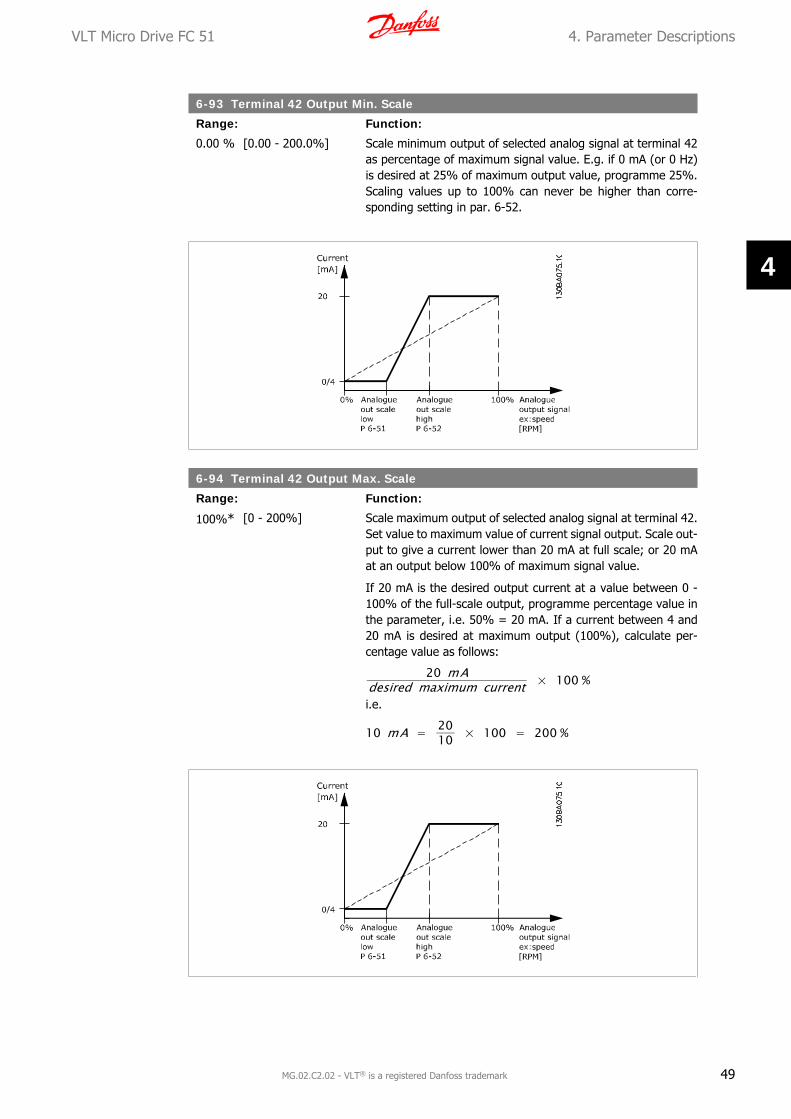
0.00 % [0.00 - 200.0%] Scale minimum output of selected analog signal at terminal 42as percentage of maximum signal value. E.g. if 0 mA (or 0 Hz)is desired at 25% of maximum output value, programme 25%.Scaling values up to 100% can never be higher than corre-sponding setting in par. 6-52.
6-94 Terminal 42 Output Max. Scale
Range: Function:
100%* [0 - 200%] Scale maximum output of selected analog signal at terminal 42.Set value to maximum value of current signal output. Scale out-put to give a current lower than 20 mA at full scale; or 20 mAat an output below 100% of maximum signal value.
If 20 mA is the desired output current at a value between 0 -100% of the full-scale output, programme percentage value inthe parameter, i.e. 50% = 20 mA. If a current between 4 and20 mA is desired at maximum output (100%), calculate per-centage value as follows:
20 mAdesired maximum current × 100 %
i.e.
10 mA = 2010 × 100 = 200 %
VLT Micro Drive FC 51 4. Parameter Descriptions
MG.02.C2.02 - VLT® is a registered Danfoss trademark 49
4
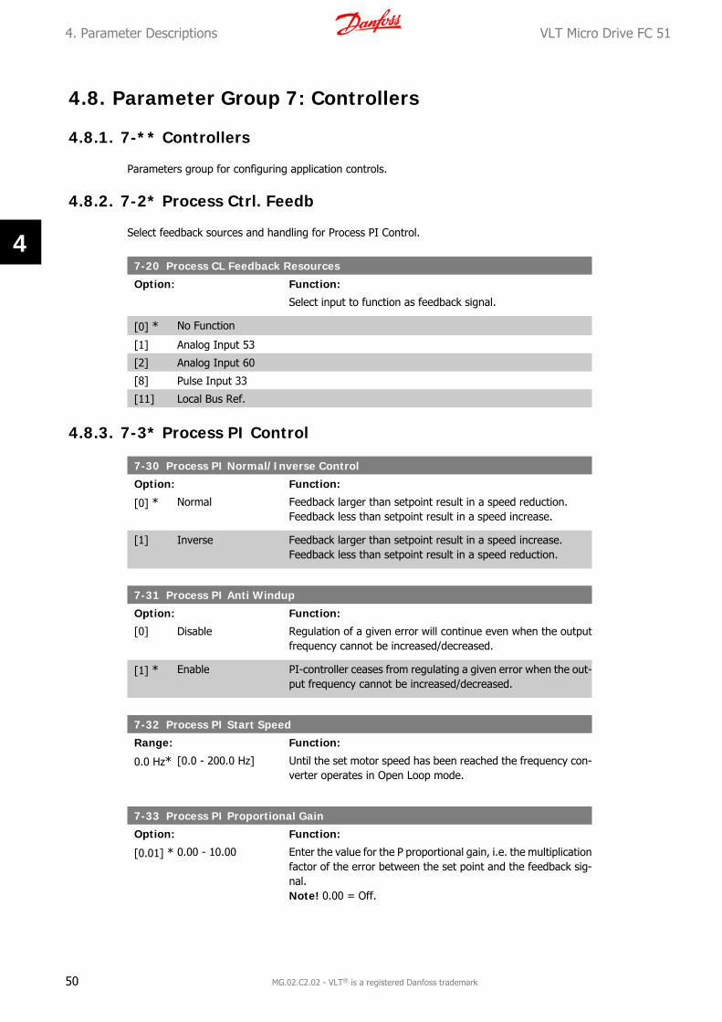
4.8. Parameter Group 7: Controllers
4.8.1. 7-** Controllers
Parameters group for configuring application controls.
4.8.2. 7-2* Process Ctrl. Feedb
Select feedback sources and handling for Process PI Control.
7-20 Process CL Feedback Resources
Option: Function:
Select input to function as feedback signal.
[0] * No Function
[1] Analog Input 53
[2] Analog Input 60
[8] Pulse Input 33
[11] Local Bus Ref.
4.8.3. 7-3* Process PI Control
7-30 Process PI Normal/Inverse Control
Option: Function:
[0] * Normal Feedback larger than setpoint result in a speed reduction.Feedback less than setpoint result in a speed increase.
[1] Inverse Feedback larger than setpoint result in a speed increase.Feedback less than setpoint result in a speed reduction.
7-31 Process PI Anti Windup
Option: Function:
[0] Disable Regulation of a given error will continue even when the outputfrequency cannot be increased/decreased.
[1] * Enable PI-controller ceases from regulating a given error when the out-put frequency cannot be increased/decreased.
7-32 Process PI Start Speed
Range: Function:
0.0 Hz* [0.0 - 200.0 Hz] Until the set motor speed has been reached the frequency con-verter operates in Open Loop mode.
7-33 Process PI Proportional Gain
Option: Function:
[0.01] * 0.00 - 10.00 Enter the value for the P proportional gain, i.e. the multiplicationfactor of the error between the set point and the feedback sig-nal.Note! 0.00 = Off.
4. Parameter Descriptions VLT Micro Drive FC 51
50 MG.02.C2.02 - VLT® is a registered Danfoss trademark
4

7-34 Process PI Integral Time
Range: Function:
9999 s* [0.01 - 999.0 s] The integrator provides an increasing gain at a constant errorbetween the set point and the feedback signal. The integral timeis the time needed by the integrator to reach the same gain asthe proportional gain.
7-38 Process Feed Forward Factor
Range: Function:
0%* [0 - 400%] The FF factor sends a part of the reference signal around the PIcontroller which then only affects part of the control signal.By activating the FF factor less overshoot and high dynamics aregained when changing the setpoint.This parameter is always active when par. 1-00 ConfigurationMode is set to Process [3].
7-39 On Reference Bandwidth
Range: Function:
5% [0 - 200% ] Enter the value for the On Reference Bandwidth.The PI control error is the difference between setpoint andfeedback and when this is less than the value set in this param-eter the On Reference is active.
VLT Micro Drive FC 51 4. Parameter Descriptions
MG.02.C2.02 - VLT® is a registered Danfoss trademark 51
4

4.9. Parameter Group 8: Communication
4.9.1. 8-** Communication
Parameter group for configuring communication.
4.9.2. 8-0* General Settings
Use this parameter group for configuring the general settings for communication.
8-01 Control Site
Option: Function:
[0] * Digital and ControlWord
Use both digital input and control word as control.
[1] Digital Only Use digital input as control.
[2] Control Word Only Use control word only as control.
NB!The setting in this parameter overrules settings inpar. 8-50 to 8-56.
8-02 Control Word Source
Option: Function:
[0] None Function is inactive
[1] * FC RS485 Monitoring control word source is done via serial communicationport RS485.
8-03 Control Word Timeout Time
Range: Function:
1.0 s* [0.1 - 6500 s] Enter time to pass before control word timeout function (par.8-04) must be carried out.
8-04 Control Word Timeout Function
Option: Function:
Select the action to be taken in case of a timeout.
[0] * Off No function.
[1] Freeze Output Freeze output until communication resumes.
[2] Stop Stop with auto restart when communication resumes.
[3] Jogging Run motor at jog frequency until communication resumes.
[4] Max. Speed Run motor at max. frequency until communication resumes.
[5] Stop and Trip Stop motor, then reset frequency converter in order to restarteither via LCP or digital input.
4. Parameter Descriptions VLT Micro Drive FC 51
52 MG.02.C2.02 - VLT® is a registered Danfoss trademark
4
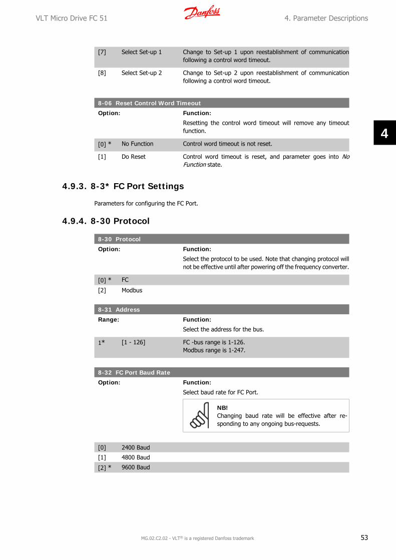
[7] Select Set-up 1 Change to Set-up 1 upon reestablishment of communicationfollowing a control word timeout.
[8] Select Set-up 2 Change to Set-up 2 upon reestablishment of communicationfollowing a control word timeout.
8-06 Reset Control Word Timeout
Option: Function:
Resetting the control word timeout will remove any timeoutfunction.
[0] * No Function Control word timeout is not reset.
[1] Do Reset Control word timeout is reset, and parameter goes into NoFunction state.
4.9.3. 8-3* FC Port Settings
Parameters for configuring the FC Port.
4.9.4. 8-30 Protocol
8-30 Protocol
Option: Function:
Select the protocol to be used. Note that changing protocol willnot be effective until after powering off the frequency converter.
[0] * FC
[2] Modbus
8-31 Address
Range: Function:
Select the address for the bus.
1* [1 - 126] FC -bus range is 1-126.Modbus range is 1-247.
8-32 FC Port Baud Rate
Option: Function:
Select baud rate for FC Port.
NB!Changing baud rate will be effective after re-sponding to any ongoing bus-requests.
[0] 2400 Baud
[1] 4800 Baud
[2] * 9600 Baud
VLT Micro Drive FC 51 4. Parameter Descriptions
MG.02.C2.02 - VLT® is a registered Danfoss trademark 53
4

8-33 FC Port Parity
Option: Function:
This parameter only affects Modbus as FC bus always has evenparity.
[0] * No Parity
[1] Odd parity
[2] No Parity (2 stopbit)
[3] No Parity (1 stopbit)
8-35 Minimum Response Delay
Range: Function:
10 ms [1 - 500 ms] Specify minimum delay time between receiving a request andtransmitting a response.
8-36 Max Response Delay
Range: Function:
5.000 s* [0.010 - 10.00 s] Specify maximum permissible delay time between transmittinga request and receiving a response. Exceeding this time delaycauses control word timeout.
4.9.5. 8-5* Digital/Bus
Parameters for configuring control word Digital/Bus merging.
NB!Parameters are only active when par. 8-01, Control SIte, is set to Digital and controlword [0].
8-50 Coasting Select
Option: Function:
Select control of coasting function via digital input and/or bus.
[0] Digital Input Activation via a digital input.
[1] Bus Activation via serial communication port.
[2] LogicAnd Activation via serial communication port and a digital input.
[3] * LogicOr Activation via serial communication port or a digital input.
8-51 Quick Stop Select
Option: Function:
Select control of quick stop function via digital input and/or bus.
[0] Digital Input Activation via a digital input.
[1] Bus Activation via serial communication port.
[2] LogicAnd Activation via serial communication port and a digital input.
4. Parameter Descriptions VLT Micro Drive FC 51
54 MG.02.C2.02 - VLT® is a registered Danfoss trademark
4
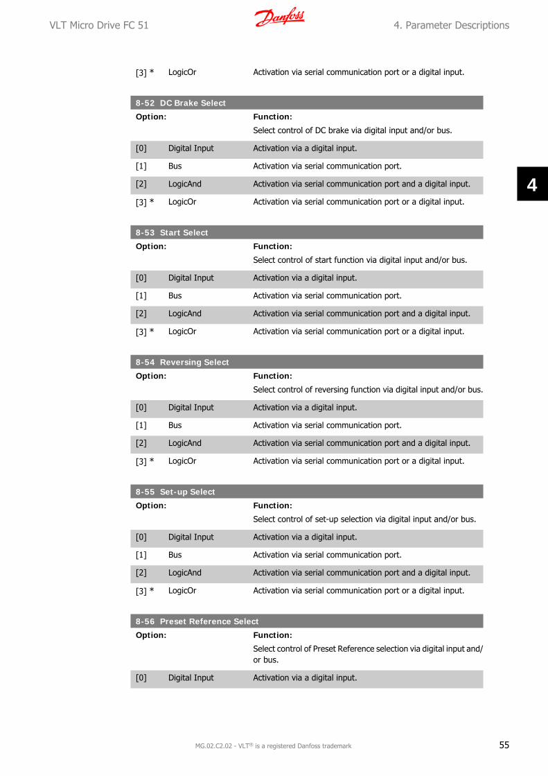
[3] * LogicOr Activation via serial communication port or a digital input.
8-52 DC Brake Select
Option: Function:
Select control of DC brake via digital input and/or bus.
[0] Digital Input Activation via a digital input.
[1] Bus Activation via serial communication port.
[2] LogicAnd Activation via serial communication port and a digital input.
[3] * LogicOr Activation via serial communication port or a digital input.
8-53 Start Select
Option: Function:
Select control of start function via digital input and/or bus.
[0] Digital Input Activation via a digital input.
[1] Bus Activation via serial communication port.
[2] LogicAnd Activation via serial communication port and a digital input.
[3] * LogicOr Activation via serial communication port or a digital input.
8-54 Reversing Select
Option: Function:
Select control of reversing function via digital input and/or bus.
[0] Digital Input Activation via a digital input.
[1] Bus Activation via serial communication port.
[2] LogicAnd Activation via serial communication port and a digital input.
[3] * LogicOr Activation via serial communication port or a digital input.
8-55 Set-up Select
Option: Function:
Select control of set-up selection via digital input and/or bus.
[0] Digital Input Activation via a digital input.
[1] Bus Activation via serial communication port.
[2] LogicAnd Activation via serial communication port and a digital input.
[3] * LogicOr Activation via serial communication port or a digital input.
8-56 Preset Reference Select
Option: Function:
Select control of Preset Reference selection via digital input and/or bus.
[0] Digital Input Activation via a digital input.
VLT Micro Drive FC 51 4. Parameter Descriptions
MG.02.C2.02 - VLT® is a registered Danfoss trademark 55
4
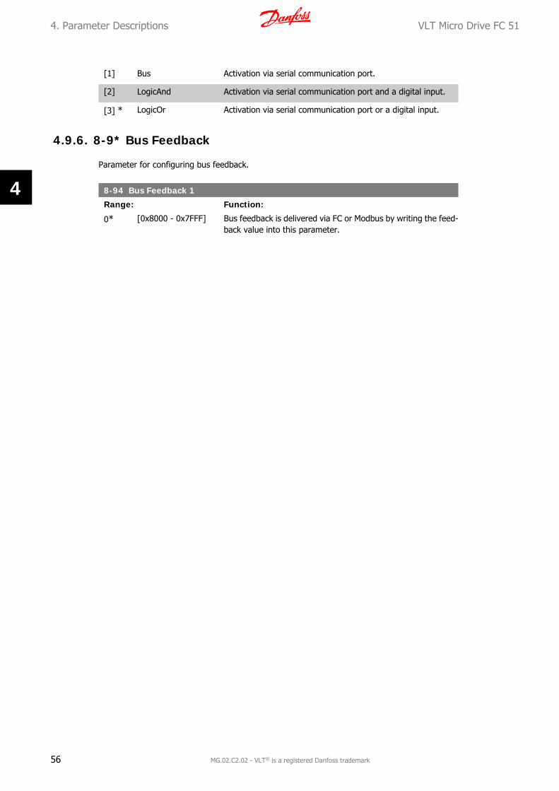
[1] Bus Activation via serial communication port.
[2] LogicAnd Activation via serial communication port and a digital input.
[3] * LogicOr Activation via serial communication port or a digital input.
4.9.6. 8-9* Bus Feedback
Parameter for configuring bus feedback.
8-94 Bus Feedback 1
Range: Function:
0* [0x8000 - 0x7FFF] Bus feedback is delivered via FC or Modbus by writing the feed-back value into this parameter.
4. Parameter Descriptions VLT Micro Drive FC 51
56 MG.02.C2.02 - VLT® is a registered Danfoss trademark
4
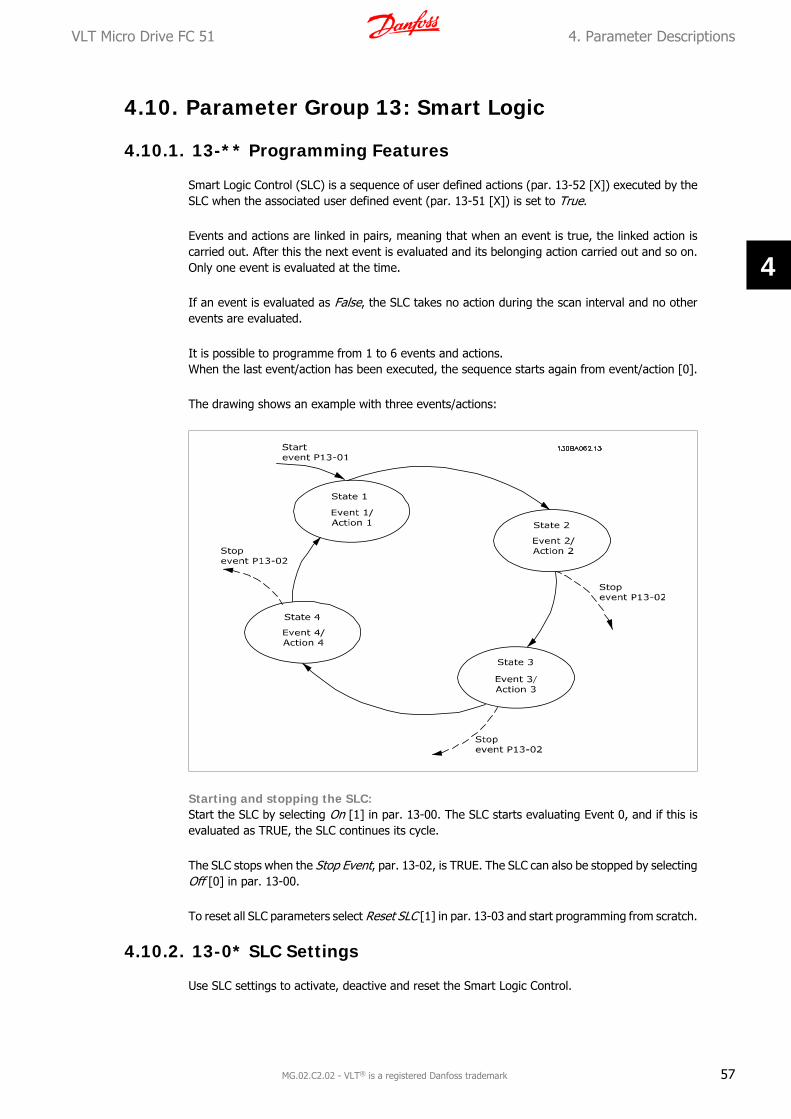
4.10. Parameter Group 13: Smart Logic
4.10.1. 13-** Programming Features
Smart Logic Control (SLC) is a sequence of user defined actions (par. 13-52 [X]) executed by theSLC when the associated user defined event (par. 13-51 [X]) is set to True.
Events and actions are linked in pairs, meaning that when an event is true, the linked action iscarried out. After this the next event is evaluated and its belonging action carried out and so on.Only one event is evaluated at the time.
If an event is evaluated as False, the SLC takes no action during the scan interval and no otherevents are evaluated.
It is possible to programme from 1 to 6 events and actions.When the last event/action has been executed, the sequence starts again from event/action [0].
The drawing shows an example with three events/actions:
Starting and stopping the SLC:Start the SLC by selecting On [1] in par. 13-00. The SLC starts evaluating Event 0, and if this isevaluated as TRUE, the SLC continues its cycle.
The SLC stops when the Stop Event, par. 13-02, is TRUE. The SLC can also be stopped by selectingOff [0] in par. 13-00.
To reset all SLC parameters select Reset SLC [1] in par. 13-03 and start programming from scratch.
4.10.2. 13-0* SLC Settings
Use SLC settings to activate, deactive and reset the Smart Logic Control.
VLT Micro Drive FC 51 4. Parameter Descriptions
MG.02.C2.02 - VLT® is a registered Danfoss trademark 57
4

13-00 SL Controller Mode
Option: Function:
[0] * Off Function is disabled.
[1] On SLC is active.
13-01 Start Event
Option: Function:
Select input to activate Smart Logic Control.
[0] False Enters False in logic rule.
[1] True Enters True in logic rule.
[2] Running See par. 5-4* [5] for description.
[3] InRange See par. 5-4* [7] for description.
[4] OnReference See par. 5-4* [8] for description.
[7] Out of Current Range See par. 5-4* [12] for description.
[8] BelowILow See par. 5-4* [13] for description.
[9] AboveIHigh See par. 5-4* [14] for description.
[16] ThermalWarning See par. 5-4* [21] for description.
[17] MainsOutOfRange Mains voltage is outside the specified voltage range.
[18] Reversing See par. 5-4* [25] for description.
[19] Warning A warning is active.
[20] Alarm_Trip A trip alarm is active.
[21] Alarm_TripLock A trip lock alarm is active.
[22] Comparator 0 Use result of comparator 0 in logic rule.
[23] Comparator 1 Use result of comparator 1 in logic rule.
[24] Comparator 2 Use result of comparator 2 in logic rule.
[25] Comparator 3 Use result of comparator 3 in logic rule.
[26] LogicRule 0 Use result of logic rule 0 in logic rule.
[27] LogicRule 1 Use result of logic rule 1 in logic rule.
[28] LogicRule 2 Use result of logic rule 2 in logic rule.
[29] LogicRule 3 Use result of logic rule 3 in logic rule.
[33] DigitalInput_18 Use value of DI 18 in logic rule.
[34] DigitalInput_19 Use value of DI 19 in logic rule.
[35] DigitalInput_27 Use value of DI 27 in logic rule.
[36] DigitalInput_29 Use value of DI 29 in logic rule.
[39] * StartCommand This event is True, if frequency converter is started by anymeans (digital input or other).
4. Parameter Descriptions VLT Micro Drive FC 51
58 MG.02.C2.02 - VLT® is a registered Danfoss trademark
4

[40] DriveStopped This event is True, if frequency converter is stopped or coastedby any means (digital input or other).
13-02 Stop Event
Option: Function:
Select input to activate Smart Logic Control.
[0] False Enters False in logic rule.
[1] True Enters True in logic rule.
[2] Running See par. 5-4* [5] for description.
[3] InRange See par. 5-4* [7] for description.
[4] OnReference See par. 5-4* [8] for description.
[7] Out of Current Range See par. 5-4* [12] for description.
[8] BelowILow See par. 5-4* [13] for description.
[9] AboveIHigh See par. 5-4* [14] for description.
[16] ThermalWarning See par. 5-4* [21] for description.
[17] MainsOutOfRange Mains voltage is outside the specified voltage range.
[18] Reversing See par. 5-4* [25] for description.
[19] Warning A warning is active.
[20] Alarm_Trip A trip alarm is active.
[21] Alarm_TripLock A trip lock alarm is active.
[22] Comparator 0 Use result of comparator 0 in logic rule.
[23] Comparator 1 Use result of comparator 1 in logic rule.
[24] Comparator 2 Use result of comparator 2 in logic rule.
[25] Comparator 3 Use result of comparator 3 in logic rule.
[26] LogicRule 0 Use result of logic rule 0 in logic rule.
[27] LogicRule 1 Use result of logic rule 1 in logic rule.
[28] LogicRule 2 Use result of logic rule 2 in logic rule.
[29] LogicRule 3 Use result of logic rule 3 in logic rule.
[30] SL Timeout0 Use result of timer 0 in logic rule.
[31] SL Timeout1 Use result of timer 1 in logic rule.
[32] SL Timeout2 Use result of timer 2 in logic rule.
[33] DigitalInput_18 Use value of DI 18 in logic rule.
[34] DigitalInput_19 Use value of DI 19 in logic rule.
[35] DigitalInput_27 Use value of DI 27 in logic rule.
[36] DigitalInput_29 Use value of DI 29 in logic rule.
VLT Micro Drive FC 51 4. Parameter Descriptions
MG.02.C2.02 - VLT® is a registered Danfoss trademark 59
4

[39] StartCommand This event is True, if frequency converter is started by anymeans (digital input or other).
[40] * DriveStopped This event is True, if frequency converter is stopped or coastedby any means (digital input or other).
13-03 Reset SLC
Option: Function:
[0] * Do Not Reset Retains all settings programmed in parameter group 13.
[1] Reset SLC Reset all group 13 parameters to default settings.
4.10.3. 13-1* Comparators
Comparators are used for comparing continuous variables (i.e. output frequency, output current,analog input etc.) to fixed preset values. In addition, there are digital values that will be comparedto fixed time values. See explanation in par. 13-10. Comparators are evaluated once in each scaninterval. Use the result (TRUE or FALSE) directly. All parameters in this parameter group are arrayparameters with index 0 to 5. Select index 0 to programme Comparator 0, select index 1 to pro-gramme Comparator 1, and so on.
13-10 Comparator Operand
Array [4]
Select variable to be monitored by comparator.
[0] * Disabled Comparator is disabled.
[1] Reference Resulting remote reference (not local) as a percentage.
[2] Feedback Feedback in either [RPM] or [Hz].
[3] MotorSpeed Motor speed in Hz.
[4] MotorCurrent Motor current in [A].
[6] MotorPower Motor power in either [kW] or [Hz].
[7] MotorVoltage Motor voltage in [V].
[8] DCLinkVoltage DC-link voltage in [V].
[9] MotorThermal Expressed as a percentage.
[10] DriveThermal Expressed as a percentage.
[11] HeatSink Tempera-ture
Expressed as a percentage.
[12] AnalogInput53 Expressed as a percentage.
[13] AnalogInput60 Expressed as a percentage.
[18] PulseInput33 Expressed as a percentage.
[20] AlarmNumber Shows number of the alarm.
[30] CounterA Number of counts.
[31] CounterB Number of counts.
4. Parameter Descriptions VLT Micro Drive FC 51
60 MG.02.C2.02 - VLT® is a registered Danfoss trademark
4

13-11 Comparator Operator
Array [4]
Select operator to be used in comparison.
[0] Less Than < Result of evaluation is True if variable selected in par. 13-10 issmaller than fixed value in par. 13-12. Result is False if variableselected in par. 13-10 is greater than fixed value in par. 13-12.
[1] * Approximately equals≈
Result of evaluation is True if variable selected in par. 13-10 isapproximately equal to fixed value in par. 13-12.
[2] Greater Than > Inverse logic of option [0].
13-12 Comparator Value
Array [4]
0.0* [-9999 - 9999] Enter “trigger level” for variable monitored by this comparator.
4.10.4. 13-2* Timers
Use the timer results to define an event (par. 13-51) or as boolean input in a logic rule (par. 13-40,13-42 or 13-44).
When timer value has elapsed timer changes state from False to True.
13-20 SL Controller Timer
Array [3]
0.0 s* [0.0 - 3600 s] Enter value to define duration of the False output from pro-grammed timer. A timer is only False if it is started by an actionand until the given timer value has elapsed.
4.10.5. 13-4* Logic Rules
Combine up to three boolean inputs (TRUE / FALSE inputs) from timers, comparators, digital in-puts, status bits and events using the logical operators AND, OR, and NOT. Select boolean inputsfor the calculation in par. 13-40, 13-42, and 13-44. Define the operators used to logically combinethe selected inputs in par. 13-41 and 13-43.
Priority of calculationThe results of par. 13-40, 13-41, and 13-42 are calculated first. The outcome (TRUE / FALSE) ofthis calculation is combined with the settings of par. 13-43 and 13-44, yielding the final result(TRUE / FALSE) of the logic rule.
13-40 Logic Rule Boolean 1
Array [4]
Select first boolean input for selected logic rule.
[0] * False Enters False in logic rule.
[1] True Enters True in logic rule.
[2] Running See par. 5-4* [5] for description.
[3] InRange See par. 5-4* [7] for description.
VLT Micro Drive FC 51 4. Parameter Descriptions
MG.02.C2.02 - VLT® is a registered Danfoss trademark 61
4
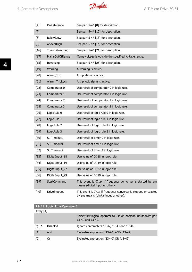
[4] OnReference See par. 5-4* [8] for description.
[7] See par. 5-4* [12] for description.
[8] BelowILow See par. 5-4* [13] for description.
[9] AboveIHigh See par. 5-4* [14] for description.
[16] ThermalWarning See par. 5-4* [21] for description.
[17] MainsOutOfRange Mains voltage is outside the specified voltage range.
[18] Reversing See par. 5-4* [25] for description.
[19] Warning A warning is active.
[20] Alarm_Trip A trip alarm is active.
[21] Alarm_TripLock A trip lock alarm is active.
[22] Comparator 0 Use result of comparator 0 in logic rule.
[23] Comparator 1 Use result of comparator 1 in logic rule.
[24] Comparator 2 Use result of comparator 2 in logic rule.
[25] Comparator 3 Use result of comparator 3 in logic rule.
[26] LogicRule 0 Use result of logic rule 0 in logic rule.
[27] LogicRule 1 Use result of logic rule 1 in logic rule.
[28] LogicRule 2 Use result of logic rule 2 in logic rule.
[29] LogicRule 3 Use result of logic rule 3 in logic rule.
[30] SL Timeout0 Use result of timer 0 in logic rule.
[31] SL Timeout1 Use result of timer 1 in logic rule.
[32] SL Timeout2 Use result of timer 2 in logic rule.
[33] DigitalInput_18 Use value of DI 18 in logic rule.
[34] DigitalInput_19 Use value of DI 19 in logic rule.
[35] DigitalInput_27 Use value of DI 27 in logic rule.
[36] DigitalInput_29 Use value of DI 29 in logic rule.
[39] StartCommand This event is True, if frequency converter is started by anymeans (digital input or other).
[40] DriveStopped This event is True, if frequency converter is stopped or coastedby any means (digital input or other).
13-41 Logic Rule Operator 1
Array [4]
Select first logical operator to use on boolean inputs from par.13-40 and 13-42.
[0] * Disabled Ignores parameters 13-42, 13-43 and 13-44.
[1] And Evaluates expression [13-40] AND [13-42].
[2] Or Evaluates expression [13-40] OR [13-42].
4. Parameter Descriptions VLT Micro Drive FC 51
62 MG.02.C2.02 - VLT® is a registered Danfoss trademark
4
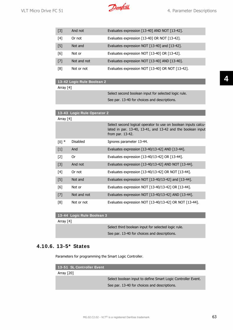
[3] And not Evaluates expression [13-40] AND NOT [13-42].
[4] Or not Evaluates expression [13-40] OR NOT [13-42].
[5] Not and Evaluates expression NOT [13-40] and [13-42].
[6] Not or Evaluates expression NOT [13-40] OR [13-42].
[7] Not and not Evaluates expression NOT [13-40] AND [13-40].
[8] Not or not Evaluates expression NOT [13-40] OR NOT [13-42].
13-42 Logic Rule Boolean 2
Array [4]
Select second boolean input for selected logic rule.
See par. 13-40 for choices and descriptions.
13-43 Logic Rule Operator 2
Array [4]
Select second logical operator to use on boolean inputs calcu-lated in par. 13-40, 13-41, and 13-42 and the boolean inputfrom par. 13-42.
[0] * Disabled Ignores parameter 13-44.
[1] And Evaluates expression [13-40/13-42] AND [13-44].
[2] Or Evaluates expression [13-40/13-42] OR [13-44].
[3] And not Evaluates expression [13-40/13-42] AND NOT [13-44].
[4] Or not Evaluates expression [13-40/13-42] OR NOT [13-44].
[5] Not and Evaluates expression NOT [13-40/13-42] and [13-44].
[6] Not or Evaluates expression NOT [13-40/13-42] OR [13-44].
[7] Not and not Evaluates expression NOT [13-40/13-42] AND [13-44].
[8] Not or not Evaluates expression NOT [13-40/13-42] OR NOT [13-44].
13-44 Logic Rule Boolean 3
Array [4]
Select third boolean input for selected logic rule.
See par. 13-40 for choices and descriptions.
4.10.6. 13-5* States
Parameters for programming the Smart Logic Controller.
13-51 SL Controller Event
Array [20]
Select boolean input to define Smart Logic Controller Event.
See par. 13-40 for choices and descriptions.
VLT Micro Drive FC 51 4. Parameter Descriptions
MG.02.C2.02 - VLT® is a registered Danfoss trademark 63
4
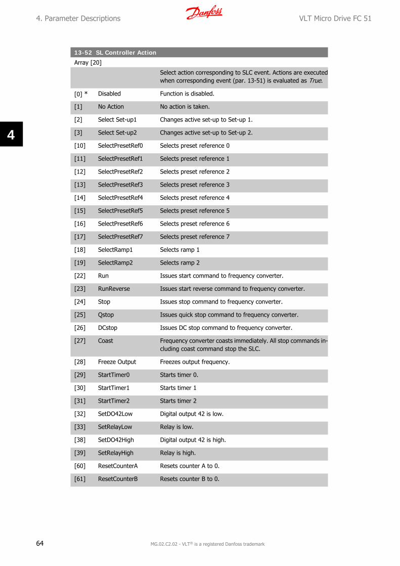
13-52 SL Controller Action
Array [20]
Select action corresponding to SLC event. Actions are executedwhen corresponding event (par. 13-51) is evaluated as True.
[0] * Disabled Function is disabled.
[1] No Action No action is taken.
[2] Select Set-up1 Changes active set-up to Set-up 1.
[3] Select Set-up2 Changes active set-up to Set-up 2.
[10] SelectPresetRef0 Selects preset reference 0
[11] SelectPresetRef1 Selects preset reference 1
[12] SelectPresetRef2 Selects preset reference 2
[13] SelectPresetRef3 Selects preset reference 3
[14] SelectPresetRef4 Selects preset reference 4
[15] SelectPresetRef5 Selects preset reference 5
[16] SelectPresetRef6 Selects preset reference 6
[17] SelectPresetRef7 Selects preset reference 7
[18] SelectRamp1 Selects ramp 1
[19] SelectRamp2 Selects ramp 2
[22] Run Issues start command to frequency converter.
[23] RunReverse Issues start reverse command to frequency converter.
[24] Stop Issues stop command to frequency converter.
[25] Qstop Issues quick stop command to frequency converter.
[26] DCstop Issues DC stop command to frequency converter.
[27] Coast Frequency converter coasts immediately. All stop commands in-cluding coast command stop the SLC.
[28] Freeze Output Freezes output frequency.
[29] StartTimer0 Starts timer 0.
[30] StartTimer1 Starts timer 1
[31] StartTimer2 Starts timer 2
[32] SetDO42Low Digital output 42 is low.
[33] SetRelayLow Relay is low.
[38] SetDO42High Digital output 42 is high.
[39] SetRelayHigh Relay is high.
[60] ResetCounterA Resets counter A to 0.
[61] ResetCounterB Resets counter B to 0.
4. Parameter Descriptions VLT Micro Drive FC 51
64 MG.02.C2.02 - VLT® is a registered Danfoss trademark
4

4.11. Parameter Group 14: Special Functions
4.11.1. 14-** Special Functions
Parameter group for configuring special frequency converter functions.
4.11.2. Inverter Switching, 14-0*
Parameters for configuring the inverter switching.
14-01 Switching Frequency
Option: Function:
Select the switching frequency in order to minimize e.g. acousticnoise and power loss or maximizing efficiency.
[0] 2 KHz
[1] * 4 KHz
[2] 8 KHz
[3] 12 KHz
[4] 16 KHz
14-03 Overmodulation
Option: Function:
This feature allows more accurate speed control near and overnominal speed (50/60 Hz). Another advantage with overmodu-lation is the ability of staying at a constant speed even thoughmains is dropping.
[0] Off Disables the overmodulation function to avoid torque ripple onthe motor shaft.
[1] * On Connects the overmodulation function to obtain an output volt-age up to 15% greater than mains voltage.
4.11.3. 14-1* Mains Monitoring
This parameter group supplies functions for handling imbalance on mains.
14-12 Functions at Mains Imbalance
Option: Function:
Operation under severe mains imbalance conditions reducesdrive lift time.
Select function to take place when severe mains imbalance isdetected.
[0] * Trip Frequency converter trips.
[1] Warning Frequency converter issues a warning.
[2] Disabled No action taken.
VLT Micro Drive FC 51 4. Parameter Descriptions
MG.02.C2.02 - VLT® is a registered Danfoss trademark 65
4

4.11.4. Trip Reset, 14-2*
Parameters for configuring auto reset handling, special trip handling and control card self test orinitialisation.
14-20 Reset Mode
Option: Function:
Select reset function after tripping. Once reset, frequency con-verter can be restarted.
[0] * Manual Reset Perform reset via [reset]-button or digital inputs.
[1] AutoReset 1 Performs one automatic reset after tripping.
[2] AutoReset 2 Performs two automatic resets after tripping.
[3] AutoReset 3 Performs three automatic resets after tripping.
[4] AutoReset 4 Performs four automatic resets after tripping.
[5] AutoReset 5 Performs five automatic resets after tripping.
[6] AutoReset 6 Performs six automatic resets after tripping.
[7] AutoReset 7 Performs seven automatic resets after tripping.
[8] AutoReset 8 Performs eight automatic resets after tripping.
[9] AutoReset 9 Performs nine automatic resets after tripping.
[10] AutoReset 10 Performs ten automatic resets after tripping.
[11] AutoReset 15 Performs fifteen automatic resets after tripping.
[12] AutoReset 20 Performs twenty automatic resets after tripping.
[13] Infinite auto reset Performs an infinite number of automatic resets after tripping.
Motor may start without warning.
14-21 Automatic Restart Time
Range: Function:
10 s* [0 - 600 s] Enter time interval from trip to start of automatic reset function.This parameter is active when par. 14-20, Reset Mode, is set toAutomatic Reset [0] - [13].
4. Parameter Descriptions VLT Micro Drive FC 51
66 MG.02.C2.02 - VLT® is a registered Danfoss trademark
4

14-22 Operation Mode
Option: Function:
Use this parameter for specifying normal operation or to initial-ize all parameters, except par. 15-03, 15-04 and 15-05.
[0] * Normal Operation Frequency converter runs normal operation.
[2] Initialization Resets all parameters to default settings, except for 15-03,15-04 and 15-05. Frequency converter resets during next pow-er-up.
Par. 14-22 also reverts to default setting Normal Operation [0].
4.11.5. 14-4* Energy Optimizing
These parameters are for adjusting the energy optimization level in both Variable Torque (VT)and Automatic Energy Optimization (AEO) modes.
14-41 AEO Minimum Magnetization
Range: Function:
66%* [40 - 75%] Enter the minimum allowable magnetization for AEO. Selectinga low value reduces energy loss in the motor, but may also re-duce resistance to sudden load changes.
VLT Micro Drive FC 51 4. Parameter Descriptions
MG.02.C2.02 - VLT® is a registered Danfoss trademark 67
4
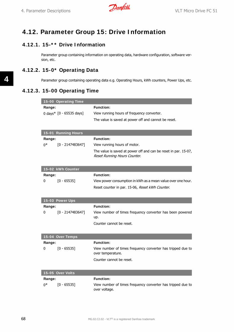
4.12. Parameter Group 15: Drive Information
4.12.1. 15-** Drive Information
Parameter group containing information on operating data, hardware configuration, software ver-sion, etc.
4.12.2. 15-0* Operating Data
Parameter group containing operating data e.g. Operating Hours, kWh counters, Power Ups, etc.
4.12.3. 15-00 Operating Time
15-00 Operating Time
Range: Function:
0 days* [0 - 65535 days] View running hours of frequency converter.
The value is saved at power off and cannot be reset.
15-01 Running Hours
Range: Function:
0* [0 - 2147483647] View running hours of motor.
The value is saved at power off and can be reset in par. 15-07,Reset Running Hours Counter.
15-02 kWh Counter
Range: Function:
0 [0 - 65535] View power consumption in kWh as a mean value over one hour.
Reset counter in par. 15-06, Reset kWh Counter.
15-03 Power Ups
Range: Function:
0 [0 - 2147483647] View number of times frequency converter has been poweredup.
Counter cannot be reset.
15-04 Over Temps
Range: Function:
0 [0 - 65535] View number of times frequency converter has tripped due toover temperature.
Counter cannot be reset.
15-05 Over Volts
Range: Function:
0* [0 - 65535] View number of times frequency converter has tripped due toover voltage.
4. Parameter Descriptions VLT Micro Drive FC 51
68 MG.02.C2.02 - VLT® is a registered Danfoss trademark
4
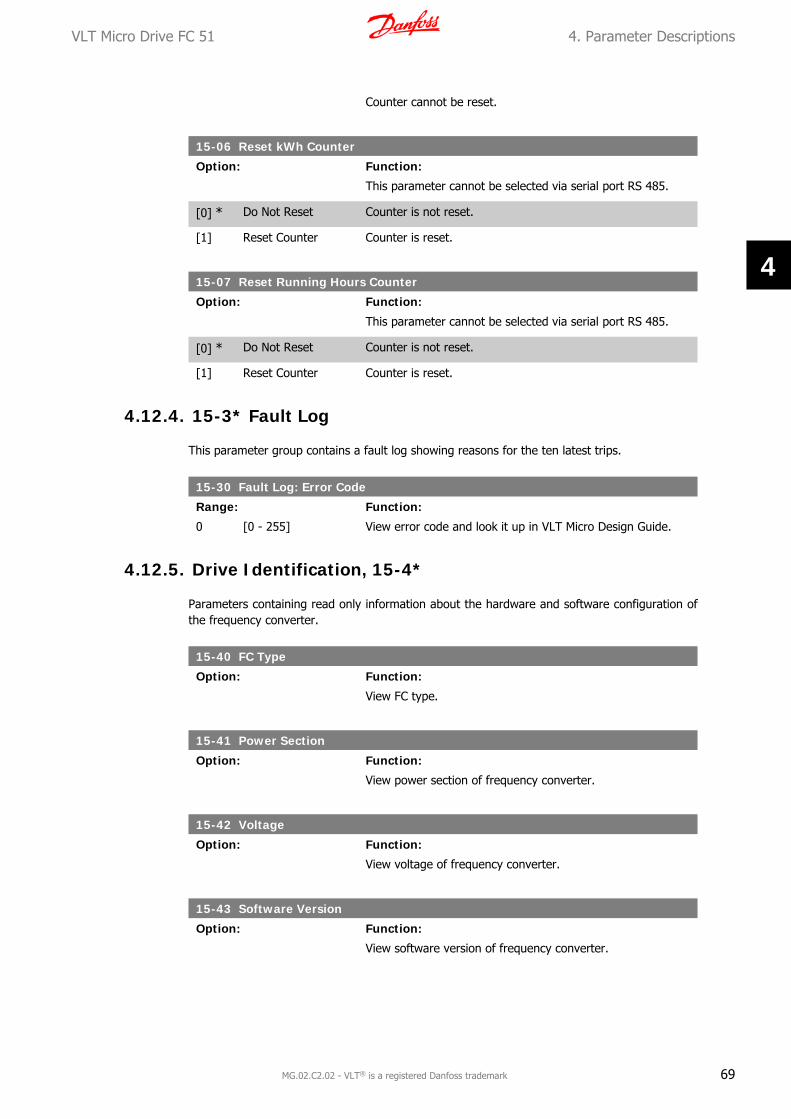
Counter cannot be reset.
15-06 Reset kWh Counter
Option: Function:
This parameter cannot be selected via serial port RS 485.
[0] * Do Not Reset Counter is not reset.
[1] Reset Counter Counter is reset.
15-07 Reset Running Hours Counter
Option: Function:
This parameter cannot be selected via serial port RS 485.
[0] * Do Not Reset Counter is not reset.
[1] Reset Counter Counter is reset.
4.12.4. 15-3* Fault Log
This parameter group contains a fault log showing reasons for the ten latest trips.
15-30 Fault Log: Error Code
Range: Function:
0 [0 - 255] View error code and look it up in VLT Micro Design Guide.
4.12.5. Drive Identification, 15-4*
Parameters containing read only information about the hardware and software configuration ofthe frequency converter.
15-40 FC Type
Option: Function:
View FC type.
15-41 Power Section
Option: Function:
View power section of frequency converter.
15-42 Voltage
Option: Function:
View voltage of frequency converter.
15-43 Software Version
Option: Function:
View software version of frequency converter.
VLT Micro Drive FC 51 4. Parameter Descriptions
MG.02.C2.02 - VLT® is a registered Danfoss trademark 69
4

15-46 Frequency Converter Ordering No
Option: Function:
View ordering number for re-ordering frequency converter in itsoriginal configuration.
15-48 LCP ID No
Option: Function:
View LCP ID number.
15-51 Frequency Converter Serial Number
Option: Function:
View frequency converter serial number.
4. Parameter Descriptions VLT Micro Drive FC 51
70 MG.02.C2.02 - VLT® is a registered Danfoss trademark
4

4.13. Parameter Group 16: Data Readouts
4.13.1. 16-** Data Readouts
Parameter group for data read-outs, e.g. actual references, voltages, control, alarm, warning andstatus words.
4.13.2. 16-0* General Status
Parameters for reading the general status, e.g. the calculated reference, the active control word,status.
16-00 Control Word
Range: Function:
0* [0 - 65535] View latest valid control word sent to frequency converter viaserial communication port.
16-01 Reference [Unit]
Range: Function:
0.000* [-4999.000 -4999.000]
View total remote reference. Total reference is sum of pulse,analog, preset, LCP potmeter, local bus and freeze reference.
16-02 Reference %
Range: Function:
0.0* [-200.0 - 200.0%] View total remote reference in percent. Total reference is sumof pulse, analog, preset, LCP potmeter, local bus and freezereference.
16-03 Status Word
Range: Function:
0* [0 - 65535] View status word sent to frequency converter via serial com-munication port.
16-05 Main Actual Value %
Range: Function:
0.00* [-100.00 - 100.00%] View two-byte word sent with status word to bus Master re-porting main actual value.
4.13.3. 16-1* Motor Status
Parameters for reading the motor status values.
16-10 Power [kW]
Range: Function:
0 kW* [0 - 99 kW] View output power in kW.
VLT Micro Drive FC 51 4. Parameter Descriptions
MG.02.C2.02 - VLT® is a registered Danfoss trademark 71
4

16-11 Power [hp]
Range: Function:
0 hp [0 - 99 hp ] View output power in hp.
16-12 Motor Voltage
Range: Function:
0.0* [0.0 - 999.9 V] View motor phase voltage.
16-13 Frequency
Range: Function:
0.0 Hz* [0.0 - 400.0 Hz] View output frequency in Hz.
16-14 Motor Current
Range: Function:
0.00 A* [0.00 - 1856.00 A] View motor phase current.
16-15 Frequency [%]
Range: Function:
0.00* [-100.00 - 100.00%] View a two-byte word reporting actual motor frequency as apercentage of par. X-XX
16-18 Motor Thermal
Range: Function:
0%* [0 - 100%] View calculated thermal motor load as percentage of estimatedthermal motor load.
4.13.4. 16-3* Drive Status
Parameters for reporting the status of the frequency converter.
16-30 DC Link Voltage
Range: Function:
0 V* [0 - 10000 V] View DC-link voltage.
16-34 Heat Sink Temp.
Range: Function:
0* [0 - 255] View heat sink temperature of frequency converter.
16-35 Inverter Thermal
Range: Function:
0%* [0 - 100%] View calculated thermal load on frequency converter in relationto estimated thermal load on frequency converter.
4. Parameter Descriptions VLT Micro Drive FC 51
72 MG.02.C2.02 - VLT® is a registered Danfoss trademark
4

16-36 Inv. Nom. Current
Range: Function:
0.00 A* [0.01 - 10000.00 A] View continuous nominal inverter current.
16-37 Inv. Max. Current
Range: Function:
0.00 A* [0.1 - 10000.00 A] View intermittent maximum inverter current (150%).
16-38 SL Controller State
Range: Function:
0* [0 - 255] View number of active SLC state.
4.13.5. 16-5* Ref. & Feedb.
Parameters for reporting the reference and feedback input.
16-50 External Reference
Range: Function:
0.0%* [-200.0 - 200.0%] View sum of all external references in percent.
16-51 Pulse Reference
Range: Function:
0.0 %* [-200.0 - 200.0%] View actual pulse input converted to a reference in percent.
16-52 Feedback
Range: Function:
0.000* [-4999.000 -4999.000]
View analog or pulse feedback in Hz.
4.13.6. 16-6* Inputs and Outputs
Parameters for reporting the digital and analog IO ports.
16-60 Digital Input 18, 19, 27, 33
Range: Function:
0* [0 - 1111] View signal states from active digital inputs.
16-61 Digital Input 29
Range: Function:
0* [0 - 1] View signal state on digital input 29.
16-62 Analog Input 53 (volt)
Range: Function:
0.00* [0.00 - 10.00 V] View input voltage on analog input terminal.
VLT Micro Drive FC 51 4. Parameter Descriptions
MG.02.C2.02 - VLT® is a registered Danfoss trademark 73
4
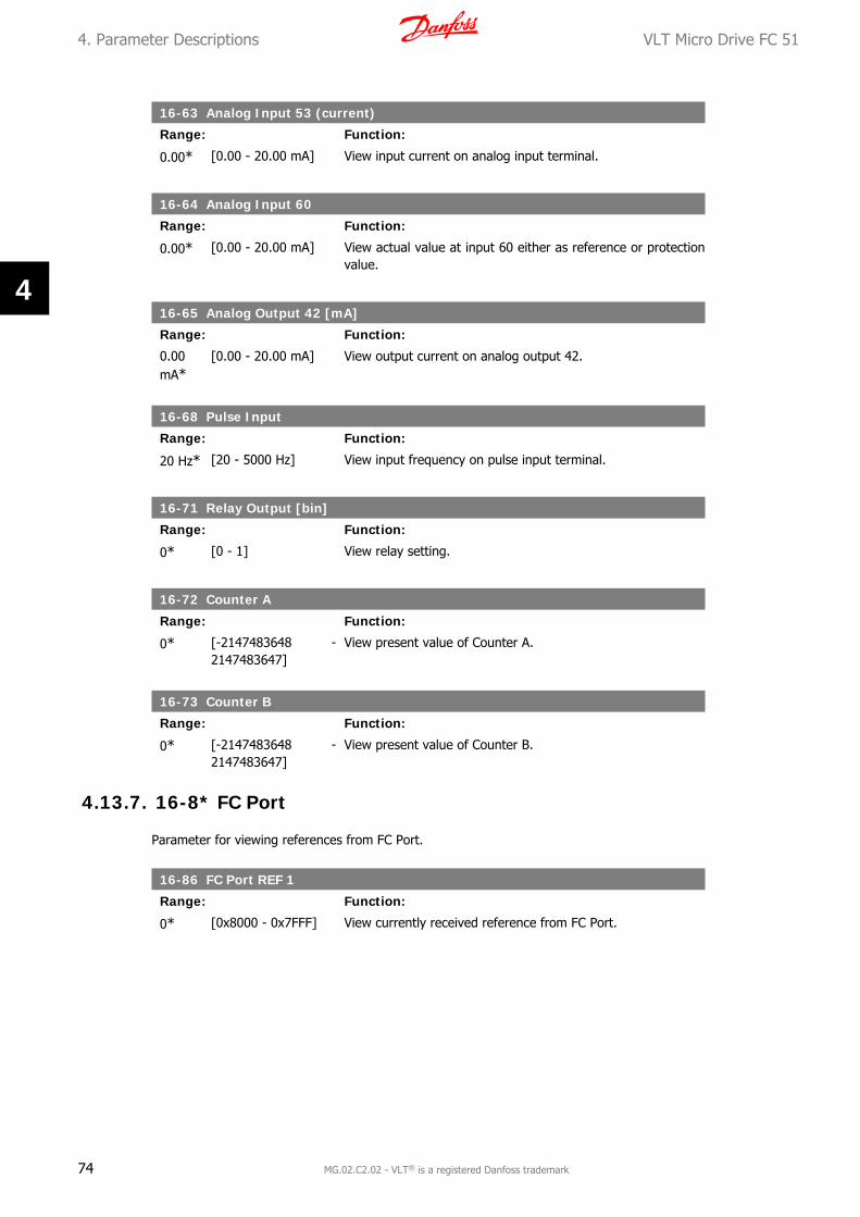
16-63 Analog Input 53 (current)
Range: Function:
0.00* [0.00 - 20.00 mA] View input current on analog input terminal.
16-64 Analog Input 60
Range: Function:
0.00* [0.00 - 20.00 mA] View actual value at input 60 either as reference or protectionvalue.
16-65 Analog Output 42 [mA]
Range: Function:
0.00mA*
[0.00 - 20.00 mA] View output current on analog output 42.
16-68 Pulse Input
Range: Function:
20 Hz* [20 - 5000 Hz] View input frequency on pulse input terminal.
16-71 Relay Output [bin]
Range: Function:
0* [0 - 1] View relay setting.
16-72 Counter A
Range: Function:
0* [-2147483648 -2147483647]
View present value of Counter A.
16-73 Counter B
Range: Function:
0* [-2147483648 -2147483647]
View present value of Counter B.
4.13.7. 16-8* FC Port
Parameter for viewing references from FC Port.
16-86 FC Port REF 1
Range: Function:
0* [0x8000 - 0x7FFF] View currently received reference from FC Port.
4. Parameter Descriptions VLT Micro Drive FC 51
74 MG.02.C2.02 - VLT® is a registered Danfoss trademark
4
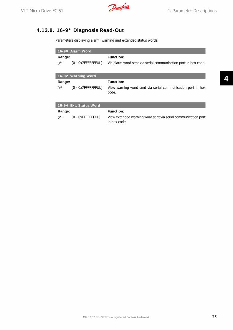
4.13.8. 16-9* Diagnosis Read-Out
Parameters displaying alarm, warning and extended status words.
16-90 Alarm Word
Range: Function:
0* [0 - 0x7FFFFFFFUL] Via alarm word sent via serial communication port in hex code.
16-92 Warning Word
Range: Function:
0* [0 - 0x7FFFFFFFUL] View warning word sent via serial communication port in hexcode.
16-94 Ext. Status Word
Range: Function:
0* [0 - 0xFFFFFFFUL] View extended warning word sent via serial communication portin hex code.
VLT Micro Drive FC 51 4. Parameter Descriptions
MG.02.C2.02 - VLT® is a registered Danfoss trademark 75
4

5. Parameter Lists VLT Micro Drive FC 51
76 MG.02.C2.02 - VLT® is a registered Danfoss trademark
5

5. Parameter Lists
Par
amet
er O
verw
iev
0-**
Ope
rati
on/D
ispl
ay0-
0* B
asic
Set
ting
s0-
03 R
egio
nal
Set
ting
s*[
0] I
nter
natio
nal
[1]
US
0-0
4 O
per.
Sta
te a
t P
ower
-up
(Han
d)[0
] Re
sum
e*[
1] F
orce
d st
op, r
ef =
old
[2]
Forc
ed s
top,
ref
= 0
0-1*
Set
-up
Han
dlin
g0-
10 A
ctiv
e Se
t-u
p*[
1] S
etup
1[2
] Se
tup
2[9
] M
ulti
Setu
p0-
11 E
dit
Set-
up
*[1]
Set
up 1
[2]
Setu
p 2
[9]
Activ
e Se
tup
0-12
Lin
k Se
tups
[0]
Not
Lin
ked
*[20
] Li
nked
0-4*
LCP
Key
pad
0-40
[H
and
on]
Key
on
LC
P[0
] D
isab
led
*[1]
Ena
bled
0-41
[O
ff /
Res
et]
Key
on
LC
P[0
] D
isab
le A
ll*[
1] E
nabl
e Al
l[2
] En
able
Res
et O
nly
0-4
2 [
Au
to o
n] K
ey o
n L
CP
[0]
Dis
able
d*[
1] E
nabl
ed0-
5* C
opy/
Save
0-50
LC
P C
opy
*[0]
No
copy
[1]
All t
o LC
P[2
] Al
l fro
m L
CP[3
] Si
ze in
dep.
fro
m L
CP0-
51 S
et-u
p C
opy
*[0]
No
copy
[1]
Copy
fro
m s
etup
1[2
] Co
py f
rom
set
up 2
[9]
Copy
fro
m F
acto
ry s
etup
0-6*
Pas
swor
d0-
60 (
Mai
n)
Men
u P
assw
ord
0 -
999
* 0
1-**
Loa
d/M
otor
1-0*
Gen
eral
Set
ting
s1-
00
Con
figu
rati
on M
ode
*[0]
Spe
ed o
pen
loop
[3]
Proc
ess
1-0
1 M
otor
Con
trol
Pri
nci
ple
[0]
U/f
*[1]
VVC
+1
-03
Tor
que
Ch
arac
teri
stic
s*[
0] C
onst
ant
torq
ue[2
] Au
tom
atic
Ene
rgy
Opt
im.
1-0
5 Lo
cal M
ode
Con
figu
rati
on[0
] Sp
eed
Ope
n Lo
op*[
2] A
s co
nfig
in p
aram
. 1-0
01-
2* M
otor
Dat
a1-
20
Mot
or P
ower
[kW
] [H
P]
0.09
kW
/ 0
.12
HP
.... 1
1 kW
/ 1
5 H
P1-
22
Mot
or V
olta
ge50
- 9
99 V
* 2
30 -
400
V1-
23
Mot
or F
requ
ency
20 -
400
Hz
* 50
Hz
1-2
4 M
otor
Cu
rren
t0.
01 -
26.
00 A
* M
otor
type
dep
.1-
25
Mot
or N
omin
al S
peed
100
- 99
99 r
pm *
Mot
orty
pe d
ep.
1-2
9 A
utom
atic
Mot
or T
unin
g (A
MT)
*[0]
Off
[2]
Enab
le A
MT
1-3*
Adv
. Mot
or D
ata
1-3
0 St
ator
Res
ista
nce
(Rs)
[Ohm
] *
Dep
. on
mot
or d
ata
1-3
3 S
tato
r Le
akag
e R
eact
ance
(X
1)
[Ohm
] *
Dep
. on
mot
or d
ata
1-3
5 M
ain
Rea
ctan
ce (
Xh
)[O
hm]
* D
ep. o
n m
otor
dat
a1-
5* L
oad
Inde
p. S
etti
ng1-
50
Mot
or M
agne
tisa
tion
at
0 Sp
eed
0 -
300
% *
100
%1-
52
Min
Spe
ed N
orm
. Mag
net
. [H
z]0.
0 -
10.0
Hz
* 0.
0 H
z1
-55
U/f
Cha
ract
eris
tic
- U
0 -
999.
9 V
1-5
6 U
/f C
hara
cter
isti
c -
F0
- 40
0 H
z1-
6* L
oad
Dep
en. S
etti
ng1
-60
Low
Spe
ed L
oad
Com
pens
atio
n0
- 19
9 %
* 1
00 %
1-6
1 H
igh
Spe
ed L
oad
Com
pen
sati
on0
- 19
9 %
* 1
00 %
1-6
2 Sl
ip C
ompe
nsa
tion
-400
- 3
99 %
* 1
00 %
1-6
3 Sl
ip C
ompe
nsa
tion
Tim
e C
onst
ant
0.05
- 5
.00
s *
0.10
s1-
7* S
tart
Adj
ustm
ents
1-7
1 St
art
Del
ay0.
0 -
10.0
s *
0.0
s1-
72
Star
t Fu
nct
ion
[0]
DC
hold
/ d
elay
tim
e[1
] D
C br
ake
/ de
lay
time
*[2]
Coa
st /
del
ay t
ime
1-7
3 Fl
yin
g St
art
*[0]
Dis
able
d[1
] En
able
d1-
8* S
top
Adj
ustm
ents
1-8
0 Fu
nct
ion
at
Stop
*[0]
Coa
st[1
] D
C ho
ld1-
82
Min
Spe
ed f
or F
un
ct. a
t St
op [
Hz]
0.0
- 20
.0 H
z *
0.0
Hz
1-9*
Mot
or T
empe
ratu
re1
-90
Mot
or T
herm
al P
rote
ctio
n*[
0] N
o pr
otec
tion
[1]
Term
isto
r w
arni
ng[2
] Th
erm
isto
r tr
ip[3
] Et
r w
arni
ng[4
] Et
r tr
ip1
-93
Ther
mis
tor
Res
ourc
e*[
0] N
one
[1]
Anal
og in
put
53[6
] D
igita
l inp
ut 2
92-
** B
rake
s2-
0* D
C-B
rake
2-0
0 D
C H
old
Cu
rren
t0
- 15
0 %
* 5
0 %
2-0
1 D
C B
rake
Cu
rren
t0
- 15
0 %
* 5
0 %
2-0
2 D
C B
raki
ng T
ime
0.0
- 60
.0 s
* 1
0.0
s2
-04
DC
Bra
ke C
ut I
n Sp
eed
0.0
- 40
0.0
Hz
* 0.
0 H
z2-
1* B
rake
Ene
rgy
Func
t.2-
10
Bra
ke F
un
ctio
n*[
0] O
ff
[1]
Res
isto
r br
ake
[2]
AC b
rake
2-11
Bra
ke R
esis
tor
(oh
m)
5 -
5000
* 5
2-16
AC
Bra
ke, M
ax c
urre
nt0
- 15
0 %
* 1
00 %
2-17
Ove
r-vo
ltag
e C
ontr
ol*[
0] D
isab
led
[1]
Enab
led
(not
at
stop
)[2
] En
able
d2-
2* M
echa
nica
l Bra
ke2-
20 R
elea
se B
rake
Cu
rren
t0.
00 -
100
.0 A
* 0
.00
A2-
22 A
ctiv
ate
Bra
ke S
peed
[H
z]0.
0 -
400.
0 H
z *
0.0
Hz
3-**
Ref
eren
ce /
Ram
ps3-
0* R
efer
ence
Lim
its
3-00
Ref
eren
ce R
ange
*[0]
Min
- M
ax[1
] -M
ax -
+M
ax3-
02 M
inim
um
Ref
eren
ce-4
999
- 49
99 *
0.0
003-
03 M
axim
um
Ref
eren
ce-4
999
- 49
99 *
50.
003-
1* R
efer
ence
s3-
10 P
rese
t R
efer
ence
-100
.0 -
100
.0 %
* 0
.00
%3-
11 J
og S
peed
[H
z]0.
0 -
400.
0 H
z *
5.0
Hz
3-12
Cat
ch u
p/sl
ow D
own
Val
ue
0.00
- 1
00.0
% *
0.0
0 %
3-14
Pre
set
Rel
ativ
e R
efer
ence
-100
.0 -
100
.0 %
* 0
.00
%3-
15 R
efer
ence
Res
ourc
e 1
[0]
No
func
tion
*[1]
Ana
log
Inpu
t 53
[2]
Anal
og in
put
60[8
] Pu
lse
inpu
t 33
[11]
Loc
al b
us r
ef[2
1] L
cp P
oten
tiom
eter
3-16
Ref
eren
ce R
esou
rce
2[0
] N
o fu
nctio
n[1
] An
alog
Inp
ut 5
3*[
2] A
nalo
g in
put
60[8
] Pu
lse
inpu
t 33
[11]
Loc
al b
us r
ef[2
1] L
cp P
oten
tiom
eter
VLT Micro Drive FC 51 5. Parameter Lists
MG.02.C2.02 - VLT® is a registered Danfoss trademark 77
5

3-17
Ref
eren
ce R
esou
rce
3[0
] N
o fu
nctio
n[1
] An
alog
Inp
ut 5
3[2
] An
alog
inpu
t 60
[8]
Puls
e in
put
33*[
11]
Loca
l bus
ref
[21]
Lcp
Pot
entio
met
er3-
18 R
elat
ive
Scal
ing
Ref
. Res
ourc
e*[
0] N
o fu
nctio
n[1
] An
alog
Inp
ut 5
3[2
] An
alog
inpu
t 60
[8]
Puls
e in
put
33[1
1] L
ocal
bus
ref
[21]
Lcp
Pot
entio
met
er3-
4* R
amp
13-
40 R
amp
1 T
ype
*[0]
Lin
ear
[2]
Sine
2 ra
mp
3-41
Ram
p 1
Ram
p u
p Ti
me
0.05
- 3
600
s *
3.00
s3-
42 R
amp
1 R
amp
Dow
n T
ime
0.05
- 3
600
s *
3.00
s3-
5* R
amp
23-
50 R
amp
2 T
ype
*[0]
Lin
ear
[2]
Sine
2 ra
mp
3-51
Ram
p 2
Ram
p u
p Ti
me
0.05
- 3
600
s *
3.00
s3-
52 R
amp
2 R
amp
dow
n T
ime
0.05
- 3
600
s *
3.00
s3-
8* O
ther
Ram
ps3-
80 J
og R
amp
Tim
e0.
05 -
360
0 s
* 3.
00 s
3-81
Qu
ick
Stop
Ram
p Ti
me
0.05
- 3
600
s *
3.00
s4-
** L
imit
s /
War
ning
s4-
1* M
otor
Lim
its
4-10
Mot
or S
peed
Dir
ecti
on[0
] Cl
ockw
ise
[1]
Coun
terC
lock
wis
e*[
2] B
oth
4-12
Mot
or S
peed
Low
Lim
it [
Hz]
0.0
- 40
0.0
Hz
* 0.
0 H
z4-
14 M
otor
Spe
ed H
igh
Lim
it [
Hz]
0.1
- 40
0.0
Hz
* 65
.0 H
z4-
16 T
orqu
e Li
mit
Mot
or M
ode
0 -
400
% *
150
%
4-17
Tor
que
Lim
it G
ener
ator
Mod
e0
- 40
0 %
* 1
00 %
4-5*
Adj
. War
ning
s4-
50 W
arn
ing
Cu
rren
t Lo
w0.
00 -
26.
00 A
* 0
.00
A4-
51 W
arn
ing
Cu
rren
t H
igh
0.00
- 2
6.00
A *
26.
00 A
4-58
Mis
sin
g M
otor
Ph
ase
Fun
ctio
n[0
] O
ff*[
1] O
n4-
6* S
peed
Byp
ass
4-61
Byp
ass
Spee
d Fr
om [
Hz]
0.0
- 40
0.0
Hz
* 0.
0 H
z4-
63 B
ypas
s Sp
eed
To [
Hz]
0.0
- 40
0.0
Hz
* 0.
0 H
z5-
1* D
igit
al I
nput
s5-
10 T
erm
inal
18
Dig
ital
In
put
[0]
No
func
tion
[1]
Rese
t[2
] Co
ast
inve
rse
[3]
Coas
t an
d re
set
inv.
[4]
Qui
ck s
top
inve
rse
[5]
DC-
brak
e in
v.[6
] St
op in
v*[
8] S
tart
[9]
Latc
hed
star
t[1
0] R
ever
sing
[11]
Sta
rt r
ever
sing
[12]
Ena
ble
star
t fo
rwar
d[1
3] E
nabl
e st
art
reve
rse
[14]
Jog
[16-
18]
Pres
et r
ef b
it 0-
2[1
9] F
reez
e re
fere
nce
[20]
Fre
eze
outp
ut[2
1] S
peed
up
[22]
Spe
ed d
own
[23]
Set
up s
elec
t bi
t 0
[28]
Cat
ch u
p[2
9] S
low
dow
n[3
4] R
amp
bit
0[6
0] C
ount
er A
(up
)[6
1] C
ount
er A
(do
wn)
[62]
Res
et c
ount
er A
[63]
Cou
nter
B (
up)
[64]
Cou
nter
B (
dow
n)[6
5] R
eset
Coun
ter
B
5-11
Ter
min
al 1
9 D
igit
al I
npu
tSe
e pa
r. 5
-10.
* [
10]
Reve
rsin
g5-
12 T
erm
inal
27
Dig
ital
In
put
See
par.
5-1
0. *
[1]
Res
et5-
13 T
erm
inal
29
Dig
ital
In
put
See
par.
5-1
0. *
[14
] Jo
g5-
15 T
erm
inal
33
Dig
ital
In
put
See
par.
5-1
0. *
[16
] Pr
eset
ref
bit
0[2
6] P
reci
se S
top
Inve
rse
[27]
Sta
rt, P
reci
se S
top
[32]
Pul
se I
nput
5-4*
Rel
ays
5-40
Fu
nct
ion
Rel
ay*[
0] N
o op
reat
ion
[1]
Cont
rol r
eady
[2]
Driv
e re
ady
[3]
Driv
e re
ady,
Rem
ote
[4]
Enab
le /
No
war
ning
[5]
Driv
e ru
nnin
g[6
] Run
ning
/ N
o w
arni
ng[7
] Run
in r
ange
/ N
o w
arni
ng[8
] Run
on
ref
/ N
o w
arni
ng[9
] Al
arm
[10]
Ala
rm o
r w
arni
ng[1
2] O
ut o
f cu
rren
t ra
nge
[13]
Bel
ow c
urre
nt, l
ow[1
4] A
bove
cur
rent
, hig
h[2
1] T
herm
al w
arni
ng[2
2] R
eady
, No
ther
mal
war
ning
[23]
Rem
ote
read
y, N
o th
erm
al w
arni
ng[2
4] R
eady
, Vol
tage
ok
[25]
Rev
erse
[26]
Bus
ok
[28]
Bra
ke,N
oWar
n[2
9] B
rake
rea
dy/N
oFau
lt[3
0] B
rake
Faul
t (I
GBT
)[3
2] M
ech.
brak
e co
ntro
l[3
6] C
ontr
ol w
ord
bit
11[5
1] L
ocal
ref
. act
ive
[52]
Rem
ote
ref.
activ
e[5
3] N
o al
arm
[54]
Sta
rt c
md
activ
e[5
5] R
unni
ng r
ever
se[5
6] D
rive
in h
and
mod
e[5
7] D
rive
in a
uto
mod
e[6
0-63
] Co
mpa
rato
r 0-
3
[70-
73]
Logi
c ru
le 0
-3[8
1] S
L di
gita
l out
put
B5-
5* P
ulse
Inp
ut5-
55
Term
inal
33
Low
Fre
quen
cy20
- 4
999
Hz
* 20
Hz
5-5
6 Te
rmin
al 3
3 H
igh
Fre
quen
cy21
- 5
000
Hz
* 50
00 H
z5-
57
Term
. 33
Low
Ref
./Fe
edb.
Val
ue
-499
9 -
4999
* 0
.000
5-5
8 Te
rm. 3
3 H
igh
Ref
./Fe
edb.
Val
ue
-499
9 -
4999
* 5
0.00
06-
** A
nalo
g In
/Out
6-0*
Ana
log
I/O
Mod
e6-
00
Live
Zer
o Ti
meo
ut
Tim
e1
- 99
s *
10
s6-
01
Live
Zer
o Ti
meo
utF
un
ctio
n*[
0] O
ff[1
] Fr
eeze
out
put
[2]
Stop
[3]
Jogg
ing
[4]
Max
spe
ed[5
] St
op a
nd t
rip6-
1* A
nalo
g In
put
16-
10
Term
inal
53
Low
Vol
tage
0.00
- 9
.99
V *
0.07
V6-
11
Term
inal
53
Hig
h V
olta
ge0.
01 -
10.
00 V
* 1
0.00
V6-
12
Term
inal
53
Low
Cu
rren
t0.
00 -
19.
99 m
A *
0.14
mA
6-1
3 Te
rmin
al 5
3 H
igh
Cu
rren
t0.
01 -
20.
00 m
A *
20.0
0 m
A6-
14
Term
. 53
Low
Ref
./Fe
edb.
Val
ue
-499
9 -
4999
* 0
.000
6-1
5 Te
rm. 5
3 H
igh
Ref
./Fe
edb.
Val
ue
-499
9 -
4999
* 5
0.00
06-
16
Term
inal
53
Filt
er T
ime
Con
stan
t0.
01 -
10.
00 s
* 0
.01
s6-
19
Term
inal
53
mod
e*[
0] V
olta
ge m
ode
[1]
Curr
ent
mod
e6-
2* A
nalo
g In
put
26-
22
Term
inal
60
Low
Cu
rren
t0.
00 -
19.
99 m
A *
0.14
mA
6-2
3 Te
rmin
al 6
0 H
igh
Cu
rren
t0.
01 -
20.
00 m
A *
20.0
0 m
A
5. Parameter Lists VLT Micro Drive FC 51
78 MG.02.C2.02 - VLT® is a registered Danfoss trademark
5

6-24
Ter
m. 6
0 Lo
w R
ef./
Feed
b. V
alu
e-4
999
- 49
99 *
0.0
006-
25 T
erm
. 60
Hig
h R
ef./
Feed
b. V
alu
e-4
999
- 49
99 *
50.
006-
26 T
erm
inal
60
Filt
er T
ime
Con
stan
t0.
01 -
10.
00 s
* 0
.01
s6-
8* L
CP p
otm
eter
6-81
LC
P p
otm
. Low
Ref
eren
ce-4
999
- 49
99 *
0.0
006-
82 L
CP
pot
m. H
igh
Ref
eren
ce-4
999
- 49
99 *
50.
006-
9* A
nalo
g O
utpu
t xx
6-90
Ter
min
al 4
2 M
ode
*[0]
0-2
0 m
A[1
] 4-
20 m
A[2
] D
igita
l Out
put
6-91
Ter
min
al 4
2 A
nal
og O
utp
ut
*[0]
No
oper
atio
n[1
0] O
utpu
t Fr
eque
ncy
[11]
Ref
eren
ce[1
2] F
eedb
ack
[13]
Mot
or C
urre
nt[1
6] P
ower
[20]
Bus
Cont
rol
6-92
Ter
min
al 4
2 D
igit
al O
utp
ut
See
par.
5-4
0*
[0]
No
Ope
ratio
n[8
0] S
L D
igita
l Out
put
A6-
93 T
erm
inal
42
Ou
tpu
t M
in S
cale
0.00
- 2
00.0
% *
0.0
0 %
6-9
4 T
erm
inal
42
Out
put
Max
Sca
le0.
00 -
200
.0 %
* 1
00.0
%7-
** C
ontr
olle
rs7-
2* P
roce
ss C
trl.
Feed
b7-
20 P
roce
ss C
L Fe
edba
ck 1
Res
ourc
e*[
0] N
oFun
ctio
n[1
] An
alog
Inp
ut 5
3[2
] An
alog
inpu
t 60
[8]
Puls
eInp
ut33
[11]
Loc
alBu
sRef
7-3*
Pro
cess
PI
Ctr
l. 7-
30 P
roce
ss P
I N
orm
al/
Inve
rse
Ctr
l*[
0] N
orm
al[1
] In
vers
e
7-31
Pro
cess
PI
An
ti W
indu
p[0
] D
isab
le*[
1] E
nabl
e7-
32 P
roce
ss P
I St
art
Spee
d0.
0 -
200.
0 H
z *
0.0
Hz
7-3
3 P
roce
ss P
I P
ropo
rtio
nal G
ain
0.00
- 1
0.00
* 0
.01
7-34
Pro
cess
PI
Inte
gral
Tim
e0.
10 -
999
9 s
* 99
99 s
7-38
Pro
cess
PI
Feed
For
war
d Fa
ctor
0 -
400
% *
0 %
7-39
On
Ref
eren
ce B
andw
idth
0 -
200
% *
5 %
8-**
Com
m. a
nd O
ptio
ns8-
0* G
ener
al S
etti
ngs
8-01
Con
trol
Sit
e*[
0] D
igita
l and
Con
trol
Wor
d[1
] D
igita
l onl
y[2
] Co
ntro
lWor
d on
ly8-
02 C
ontr
ol W
ord
Sou
rce
[0]
Non
e*[
1] F
C RS
485
8-03
Con
trol
Wor
d Ti
meo
ut
Tim
e0.
1 -
6500
s *
1.0
s8-
04 C
ontr
ol W
ord
Tim
eou
t Fu
nct
ion
*[0]
Off
[1]
Free
ze O
utpu
t[2
] St
op[3
] Jo
ggin
g[4
] M
ax. S
peed
[5]
Stop
and
trip
8-06
Res
et C
ontr
ol W
ord
Tim
eou
t*[
0] N
o Fu
nctio
n[1
] D
o re
set
8-3*
FC
Port
Set
ting
s8-
30 P
roto
col
*[0]
FC
[2]
Mod
bus
8-31
Add
ress
1 -
247
* 1
8-32
FC
Por
t B
aud
Rat
e[0
] 24
00 B
aud
[1]
4800
Bau
d*[
2] 9
600
Baud
8-3
3 FC
Por
t P
arit
y*[
0] E
ven
Parit
y, 1
Sto
p Bi
t[1
] O
dd P
arity
, 1 S
top
Bit
[2]
No
Parit
y, 1
Sto
p Bi
t[3
] N
o Pa
rity,
2 S
top
Bits
8-3
5 M
inim
um
Res
pon
se D
elay
0.00
1-0.
5 *
0.01
0 s
8-3
6 M
ax R
espo
nse
Del
ay0.
100
- 10
.00
s *
5.00
0 s
8-5*
Dig
ital
/Bus
8-5
0 C
oast
ing
Sele
ct[0
] D
igita
lInpu
t[1
] Bu
s[2
] Lo
gicA
nd*[
3] L
ogic
Or
8-5
1 Q
uic
k St
op S
elec
tSe
e pa
r. 8
-50
* [3
] Lo
gicO
r8
-52
DC
Bra
ke S
elec
tSe
e pa
r. 8
-50
* [3
] Lo
gicO
r8
-53
Star
t Se
lect
See
par.
8-5
0 *
[3]
Logi
cOr
8-5
4 R
ever
sin
g Se
lect
See
par.
8-5
0 *
[3]
Logi
cOr
8-5
5 S
et-u
p Se
lect
See
par.
8-5
0 *
[3]
Logi
cOr
8-5
6 P
rese
t R
efer
ence
Sel
ect
See
par.
8-5
0 *
[3]
Logi
cOr
8-9*
Bus
Jog
/ F
eedb
ack
8-9
4 B
us
feed
back
10x
8000
- 0
x7FF
F *
013
-**
Smar
t Lo
gic
13-0
* SL
C Se
ttin
gs1
3-0
0 S
L C
ontr
olle
r M
ode
*[0]
Off
[1]
On
13-
01 S
tart
Eve
nt
[0]
Fals
e[1
] Tr
ue[2
] Ru
nnin
g[3
] In
Rang
e[4
] O
nRef
eren
ce[7
] O
utO
fCur
rent
Ran
ge
[8]
Belo
wIL
ow[9
] Ab
oveI
Hig
h[1
6] T
herm
alW
arni
ng[1
7] M
ainO
utO
fRan
ge[1
8] R
ever
sing
[19]
War
ning
[20]
Ala
rm_T
rip[2
1] A
larm
_Trip
Lock
[22-
25]
Com
para
tor
0-3
[26-
29]
Logi
cRul
e0-3
[33]
Dig
italIn
put_
18[3
4] D
igita
lInpu
t_19
[35]
Dig
italIn
put_
27[3
6] D
igita
lInpu
t_29
[38]
Dig
italIn
put_
33*[
39]
Star
tCom
man
d[4
0] D
riveS
topp
ed13
-02
Stop
Eve
nt
See
par.
13-
01 *
[40
] D
riveS
topp
ed13
-03
Res
et S
LC*[
0] D
o no
t re
set
[1]
Rese
t SL
C13
-1*
Com
para
tors
13
-10
Com
para
tor
Ope
ran
d*[
0] D
isab
led
[1]
Refe
renc
e[2
] Fe
edba
ck[3
] M
otor
Spee
d[4
] M
otor
Curr
ent
[6]
Mot
orPo
wer
[7]
Mot
orVo
ltage
[8]
DCL
inkV
olta
ge[1
2] A
nalo
gInp
ut53
[13]
Ana
logI
nput
60[1
8] P
ulse
Inpu
t33
[20]
Ala
rmN
umbe
r[3
0] C
ount
erA
[31]
Cou
nter
B1
3-1
1 C
ompa
rato
r O
pera
tor
[0]
Less
Tha
n
VLT Micro Drive FC 51 5. Parameter Lists
MG.02.C2.02 - VLT® is a registered Danfoss trademark 79
5

*[1]
App
roxi
mat
ely
equa
ls[2
] G
reat
er T
han
13
-12
Com
para
tor
Val
ue
-999
9 -
9999
* 0
.013
-2*
Tim
ers
13-2
0 SL
Con
trol
ler
Tim
er0.
0 -
3600
s *
0.0
s13
-4*
Logi
c R
ules
13
-40
Logi
c R
ule
Boo
lean
1Se
e pa
r. 1
3-01
* [
0] F
alse
[30]
- [
32]
SL T
ime-
out
0-2
13
-41
Log
ic R
ule
Ope
rato
r 1
*[0]
Dis
able
d[1
] An
d[2
] O
r[3
] An
d no
t[4
] O
r no
t[5
] N
ot a
nd[6
] N
ot o
r[7
] N
ot a
nd n
ot[8
] N
ot o
r no
t1
3-4
2 Lo
gic
Ru
le B
oole
an 2
See
par.
13-
401
3-4
3 L
ogic
Ru
le O
pera
tor
2Se
e pa
r. 1
3-41
* [
0] D
isab
led
13
-44
Logi
c R
ule
Boo
lean
3Se
e pa
r. 1
3-40
13-5
* St
ates
13
-51
SL C
ontr
olle
r Ev
ent
See
par.
13-
401
3-5
2 S
L C
ontr
olle
r A
ctio
n*[
0] D
isab
led
[1]
NoA
ctio
n[2
] Se
lect
Setu
p1[3
] Se
lect
Setu
p2[1
0-17
] Se
lect
Pres
etRef
0-7
[18]
Sel
ectR
amp1
[19]
Sel
ectR
amp2
[22]
Run
[23]
Run
Reve
rse
[24]
Sto
p[2
5] Q
stop
[26]
DCs
top
[27]
Coa
st[2
8] F
reez
eOut
put
[29]
Sta
rtTi
mer
0[3
0] S
tart
Tim
er1
[31]
Sta
rtTi
mer
2[3
2] S
et D
igita
l Out
put
A Lo
w[3
3] S
et D
igita
l Out
put
B Lo
w[3
8] S
et D
igita
l Out
put
A H
igh
[39]
Set
Dig
ital O
utpu
t B
Hig
h[6
0] R
eset
Coun
terA
[61]
Res
etCo
unte
rB14
-**
Spec
ial F
unct
ions
14-0
* In
vert
er S
wit
chin
g14
-01
Swit
chin
g Fr
equ
ency
[0]
2 kH
z*[
1] 4
kH
z[2
] 8
kHz
[4]
16 k
Hz
14-0
3 O
verm
odul
atio
n[0
] O
ff*[
1] O
n14
-1*
Mai
ns m
onit
orin
g14
-12
Fun
ctio
n a
t m
ains
imba
lan
ce*[
0] T
rip[1
] W
arni
ng[2
] D
isab
led
14-2
* Tr
ip R
eset
14-2
0 R
eset
Mod
e*[
0] M
anua
l res
et[1
-9]
Auto
Rese
t 1-
9[1
0] A
utoR
eset
10
[11]
Aut
oRes
et 1
5[1
2] A
utoR
eset
20
[13]
Inf
inite
aut
o re
set
14-2
1 A
uto
mat
ic R
esta
rt T
ime
0 -
600
s *
10 s
14-2
2 O
pera
tion
Mod
e*[
0] N
orm
al O
pera
tion
[2]
Initi
alis
atio
n14
-26
Act
ion
At
Inve
rter
Fau
lt*[
0] T
rip[1
] W
arni
ng14
-4*
Ener
gy O
ptim
isin
g14
-41
AEO
Min
imu
m M
agn
etis
atio
n40
- 7
5 %
* 6
6 %
15-*
* D
rive
Inf
orm
atio
n15
-0*
Ope
rati
ng D
ata
15-0
0 O
pera
ting
Day
s15
-01
Ru
nni
ng H
ours
15-0
2 kW
h C
oun
ter
15-0
3 P
ower
Ups
15-0
4 O
ver
Tem
ps15
-05
Ove
r V
olts
15-0
6 R
eset
kW
h C
ount
er*[
0] D
o no
t re
set
[1]
Rese
t co
unte
r15
-07
Res
et R
un
nin
g H
ours
Cou
nte
r*[
0] D
o no
t re
set
[1]
Rese
t co
unte
r15
-3*
Faul
t Lo
g15
-30
Faul
t Lo
g: E
rror
Cod
e15
-4*
Dri
ve I
dent
ific
atio
n15
-40
FC T
ype
15-4
1 P
ower
Sec
tion
15-4
2 V
olta
ge15
-43
Soft
war
e V
ersi
on15
-46
Freq
uen
cy C
onve
rter
Ord
er. N
o15
-48
LCP
Id
No
15-5
1 Fr
eque
ncy
Con
vert
er S
eria
l No
16-*
* D
ata
Rea
dout
s16
-0*
Gen
eral
Sta
tus
16-0
0 C
ontr
ol W
ord
0 -
0XFF
FF16
-01
Ref
eren
ce [
Un
it]
-499
9 -
4999
16-0
2 R
efer
ence
%-2
00.0
- 2
00.0
%16
-03
Stat
us
Wor
d0
- 0X
FFFF
16
-05
Mai
n A
ctu
al V
alu
e [%
]-2
00.0
- 2
00.0
%16
-1*
Mot
or S
tatu
s16
-10
Pow
er [
kW]
16-1
1 P
ower
[h
p]16
-12
Mot
or V
olta
ge [
V]
16-1
3 Fr
equ
ency
[H
z]16
-14
Mot
or C
urr
ent
[A]
16-1
5 Fr
equ
ency
[%
]16
-18
Mot
or T
her
mal
[%
]
16-3
* D
rive
Sta
tus
16-
30 D
C L
ink
Vol
tage
16-
36 I
nv.
Nom
. Cu
rren
t1
6-37
In
v. M
ax. C
urr
ent
16-
38
SL
Con
trol
ler
Stat
e16
-5*
Ref
. / F
eedb
.1
6-50
Ext
ern
al R
efer
ence
16-
51 P
ulse
Ref
eren
ce1
6-52
Fee
dbac
k [U
nit
]16
-6*
Inpu
ts /
Out
puts
16-
60 D
igit
al I
npu
t 18
,19,
27,
330
- 11
111
6-61
Dig
ital
In
put
290
- 1
16-
62 A
nal
og I
npu
t 53
(vo
lt)
16-
63 A
nal
og I
npu
t 53
(cu
rren
t)1
6-64
Ana
log
Inpu
t 6
01
6-65
An
alog
Ou
tpu
t 42
[m
A]
16-
68 P
ulse
In
put
[Hz]
16-
71 R
elay
Ou
tpu
t [b
in]
16-
72 C
oun
ter
A1
6-73
Cou
nte
r B
16-8
* Fi
eldb
us /
FC
Port
16-
86 F
C P
ort
REF
10x
8000
- 0
x7FF
FF16
-9*
Dia
gnos
is R
eado
uts
16-
90 A
larm
Wor
d0
- 0X
FFFF
FFFF
16-
92 W
arn
ing
Wor
d0
- 0X
FFFF
FFFF
16-
94 E
xt. S
tatu
s W
ord
0 -
0XFF
FFFF
FF
5. Parameter Lists VLT Micro Drive FC 51
80 MG.02.C2.02 - VLT® is a registered Danfoss trademark
5

6. Troubleshooting
No.
Des
crip
tion
War
ning
Alar
mTr
ip L
ock
Caus
e of
Pro
blem
2Li
ve z
ero
erro
rX
X
Sign
al o
n te
rmin
al 5
3 or
60
is le
ss t
han
50%
of
valu
e se
t in
par
. 6-1
0, 6
-12
and
6-22
.4
Mai
ns p
hase
loss
1)X
XX
Mis
sing
pha
se o
n su
pply
sid
e, o
r to
o hi
gh v
olta
ge im
bala
nce.
Che
ck s
uppl
y vo
ltage
.7
DC
over
vol
tage
1)X
X
Inte
rmed
iate
circ
uit
volta
ge e
xcee
ds li
mit.
8D
C un
der
volta
ge1)
XX
In
term
edia
te c
ircui
t vo
ltage
dro
ps b
elow
“vo
ltage
war
ning
low
” lim
it.9
Inve
rter
ove
rload
edX
X
Mor
e th
an 1
00%
load
for
too
long
.10
Mot
or E
TR o
ver
tem
pera
ture
XX
M
otor
is t
oo h
ot d
ue t
o m
ore
than
100
% lo
ad f
or t
oo lo
ng.
11M
otor
the
rmis
tor
over
tem
pera
ture
XX
Th
erm
isto
r or
the
rmis
tor
conn
ectio
n is
dis
conn
ecte
d.12
Torq
ue li
mit
X
To
rque
exc
eeds
val
ue s
et in
eith
er p
ar. 4
-16
or 4
-17.
13O
ver
Curr
ent
XX
XIn
vert
er p
eak
curr
ent
limit
is e
xcee
ded.
14Ea
rth
faul
t
XX
Dis
char
ge f
rom
out
put
phas
es t
o gr
ound
.16
Shor
t Ci
rcui
t
XX
Shor
t-ci
rcui
t in
mot
or o
r on
mot
or t
erm
inal
s.17
Cont
rol w
ord
timeo
utX
X
No
com
mun
icat
ion
to f
requ
ency
con
vert
er.
25Br
ake
resi
stor
sho
rt-c
ircui
ted
X
XBr
ake
resi
stor
is s
hort
-circ
uite
d, t
hus
brak
e fu
nctio
n is
dis
conn
ecte
d.27
Brak
e ch
oppe
r sh
ort-
circ
uite
d
XX
Brak
e tr
ansi
stor
is s
hort
-circ
uite
d, t
hus
brak
e fu
nctio
n is
dis
conn
ecte
d.28
Brak
e ch
eck
X
Br
ake
resi
stor
is n
ot c
onne
cted
/wor
king
29Po
wer
boa
rd o
ver
tem
pX
XX
Hea
t-si
nk c
ut-o
ut t
empe
ratu
re h
as b
een
reac
hed.
30M
otor
pha
se U
mis
sing
X
XM
otor
pha
se U
is m
issi
ng. C
heck
the
pha
se.
31M
otor
pha
se V
mis
sing
X
XM
otor
pha
se V
is m
issi
ng. C
heck
the
pha
se.
32M
otor
pha
se W
mis
sing
X
XM
otor
pha
se W
is m
issi
ng. Ch
eck
the
phas
e.38
Inte
rnal
fau
lt
XX
Cont
act
loca
l Dan
foss
sup
plie
r.47
Cont
rol V
olta
ge F
ault
XX
X24
V D
C m
ay b
e ov
erlo
aded
.51
AMT
chec
k U
nom a
nd I
nom
X
W
rong
set
ting
for
mot
or v
olta
ge, m
otor
cur
rent
and
mot
or v
olta
ge.
52AM
T lo
w I
nom
X
M
otor
cur
rent
is t
oo lo
w. C
heck
set
tings
.59
Curr
ent
limit
X
VL
T ov
erlo
ad.
63M
echa
nica
l Bra
ke L
ow
X
Actu
al m
otor
cur
rent
has
not
exc
eede
d “r
elea
se b
rake
” cu
rren
t w
ithin
“st
art
dela
y” t
ime
win
dow
.80
Driv
e In
itial
ised
to
Def
ault
Valu
e
X
All p
aram
eter
set
tings
are
initi
aliz
ed t
o de
faul
t se
ttin
gs.
1) T
hese
fau
lts m
ay b
e ca
used
by
mai
ns d
isto
rtio
ns.
Inst
allin
g D
anfo
ss L
ine
Filte
rm
ay r
ectif
y th
is p
robl
em.
Tabl
e 6.
1: C
ode
list
VLT Micro Drive FC 51 6. Troubleshooting
MG.02.C2.02 - VLT® is a registered Danfoss trademark 81
6
Index116-1* Motor Status 71
AAbbreviations And Standards 8
DDisplay 9
Disposal Instruction 4
Drive Identification, 15-4* 69
EEarth Leakage Current 3
Electronic Waste 4
GGeneral Warning 8
IIndicator Lights 11
Inverter Switching, 14-0* 65
It Mains 4
LLcp 9, 10
Leakage Current 4
MMain Menu 10
Motor Direction 10
NNavigation Keys 11
Not Changeable During Operation 15
OOperation Keys 11
PParameter Number 10
QQuick Menu 10
RRated Magnetizing Current 21
Residual Current Device 4
SSet-up Number 9
Set-up Software 9
Special Functions 65
Status Menu 10
Index VLT Micro Drive FC 51
82 MG.02.C2.02 - VLT® is a registered Danfoss trademark

TTrip Reset, 14-2* 66
Type Code String 7
UUnit 10
VValue 10
VLT Micro Drive FC 51 Index
MG.02.C2.02 - VLT® is a registered Danfoss trademark 83