VLT® Micro Drive - Northrich Company - HVAC Products VLT Micro Drive offers unsurpassed...
11
1 2 3 4 12 11 5 13 8 6 4 7 9 10 6 11 13 14 4 1.800.432.6367 www.danfossdrives.com Ready—Set—Go! The VLT Micro Drive offers unsurpassed reliability, user- friendliness and condensed functionality that is extremely easy to commission. Connect motor and power cables, turn the control knob, and watch the motor speed change. Approximately 100 parameters are available to optimize energy efficiency and operation. VLT® Micro Drive 1 2 3 4 5 6 7 8 9 10 11 12 13 14 Well protected IP20 enclosure with NEMA/UL Type 1 optional; no forced airflow through electronics High quality capacitors RFI Filter Hot-pluggable LCP LCD display I/O terminals EIA-485 connection Customer relay screw terminals; wire inlet from the bottom Potentiometer Removable cover for convenient access to control terminals Mains screw terminals DC-link access Safety ground; min. 10 AWG accessible from front Motor screw terminals Manufactured to the highest quality standards The VLT® Micro Drive is a UL-listed product made in an ISO 9001-2000 certified facility. Despite its compact size and ease of installation, the VLT Micro Drive can deliver exceptional performance even in complex applications.
Transcript of VLT® Micro Drive - Northrich Company - HVAC Products VLT Micro Drive offers unsurpassed...

4 1.800.432.6367www.danfossdrives.com
1
2
3
4
12
11
5
13
8
6
4
7
9
10
6
1113
14
4 1.800.432.6367www.danfossdrives.com
Ready—Set—Go!The VLT Micro Drive offers unsurpassed reliability, user-friendliness and condensed functionality that is extremely easy to commission. Connect motor and power cables, turn the control knob, and watch the motor speed change. Approximately 100 parameters are available to optimize energy efficiency and operation.
VLT® Micro Drive
1
2
3
4
5
6
7
8
9
10
11
12
13
14
Well protected IP20 enclosure with NEMA/UL Type 1 optional; no forced airflow through electronics
High quality capacitors
RFI Filter
Hot-pluggable LCP
LCD display
I/O terminals
EIA-485 connection
Customer relay screw terminals; wire inlet from the bottom
Potentiometer
Removable cover for convenient access to control terminals
Mains screw terminals
DC-link access
Safety ground; min. 10 AWG accessible from front
Motor screw terminals
Manufactured to the highest quality standards
The VLT® Micro Drive is a UL-listed product made in an ISO 9001-2000 certified facility.
Despite its compact size and ease of installation, the VLT Micro Drive can deliver exceptional performance even in complex applications.

51.800.432.6367 www.danfossdrives.com
Small drive—high performance
• Process PI controller – Removes need for external controller
• Automatic Energy Optimization (AEO) – Lowers energy consumption
• Automatic Motor Tuning (AMT) – Utilizes motor’s full potential
• 150% motor torque up to 1 minute – Removes need for bigger drive
• Flying start (catch a spinning motor) – Provides smooth starts without tripping
• Electronic Thermal Relay (ETR) – Replaces external motor protection
• Smart Logic Controller – Helps automate application
• Built-in RFI filter – Minimizes radio frequency disturbances
Compact general purpose drive
The VLT Micro Drive is a general purpose drive designed to control AC motors up to 10 HP.
Inputs and outputs
• 5 programmable digital inputs• Activation based on switching
high or sinking low (0-24 VDC)• Pulse input 20–5000 Hz• 1 analog input (0–10 V or 0–20
mA)• 1 analog input 0–20 mA• Thermistor input (analog/
digital)• 1 analog output 0–20 mA• 1 Relay 240 VAC, 2 A• EIA-485 port with FC or Modbus
RTU protocolUser friendly
• Plug-and-play – Streamlined installation
• Minimal commissioning requirements – Quicker startup
• Settings can be copied via the local control panel – Easy setup of multiple drives
• Intuitive parameter structure – Minimal manual reading
• Compatible with MCT 10 Setup Software
– Faster startup and greater control of large installations
Reliable• Optimal heat dissipation – Longer lifetime
• High quality electronics/capacitors – Low lifetime cost
• All drives full-load tested from factory – High reliability
• Ground fault, temperature and short circuit protection
– High level of protection without the need for external devices
• Circuit boards well protected and coated – Increased robustness
Features

6 1.800.432.6367www.danfossdrives.com
True side-by-sidemounting
A compact bookstyle design allows space-saving mounting without derating.
Ensured reliability and maximum uptime
Coated electronics are standard
All VLT Micro Drives come with conformally coated circuit boards for greater longevity and reliability in harsh operating environments.
Energy efficiency 98%
High-quality VLT power modules ensure low power losses, resulting in cooler operation.
Intelligent heat management
Heat from the power semiconductors is transferred through the heatsink to the external airflow, which is routed through the cooling fins. This minimizes the air exchange inside the enclosure and protects the control circuitry from dirt and other contaminants.
122˚ F (50˚ C) ambient temperature
Highly efficient cooling allows for operation in high ambient temperatures. At 100% load, ambient temperature is rated at 104° F (40° C).
Designed for robust operation in a variety of applications
VLT® Micro Drive
Built-in brake functions
With built-in DC and AC brake functions, the VLT® Micro Drive can transform kinetic energy in the application into braking power to slow the motor. A brake chopper is built into all VLT Micro drives 2 HP and up.
Minimal penetration of dust
The VLT Micro Drive is designed to separate forced ventilation air from the electronics. Printed circuit boards are well protected inside the drive.
Built-in RFI protection
A built-in RFI filter limits radio disturbance from motor cables, allowing for 50’ motor cables (shielded).
Built-in smart logic controllerThe smart logic controller is a simple yet very clever way to enable the drive, motor and application to work together.
The smart logic controller is able to monitor any parameter that can be characterized as “true” or “false.” This includes digital commands and also logic expressions, which allows even sensor outputs to influence the operation. For example, temperature, pressure, flow, time, load, frequency, voltage and other parameters can be combined with the operators “>”, “<”, “=”, “and” and “or” form logic expressions that are false or true.
That is why Danfoss calls it a “logic” controller. As a result, you can program the controller to react to most any event.
71.800.432.6367 www.danfossdrives.com
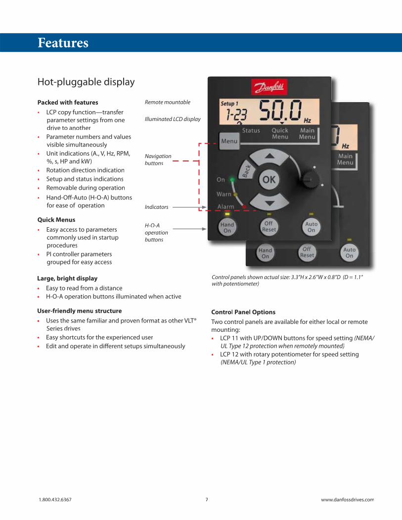
Hot-pluggable display
Packed with features• LCP copy function—transfer
parameter settings from onedrive to another
• Parameter numbers and valuesvisible simultaneously
• Unit indications (A., V, Hz, RPM,%, s, HP and kW)
• Rotation direction indication• Setup and status indications• Removable during operation• Hand-Off-Auto (H-O-A) buttons
for ease of operation
Quick Menus• Easy access to parameters
commonly used in startupprocedures
• PI controller parametersgrouped for easy access
Control Panel OptionsTwo control panels are available for either local or remotemounting:• LCP 11 with UP/DOWN buttons for speed setting (NEMA/
UL Type 12 protection when remotely mounted)• LCP 12 with rotary potentiometer for speed setting
(NEMA/UL Type 1 protection)
Illuminated LCD display
Remote mountable
Navigationbuttons
Indicators
H-O-Aoperationbuttons
Control panels shown actual size: 3.3”H x 2.6”W x 0.8”D (D = 1.1” with potentiometer)
Large, bright display• Easy to read from a distance• H-O-A operation buttons illuminated when active
User-friendly menu structure• Uses the same familiar and proven format as other VLT®
Series drives• Easy shortcuts for the experienced user• Edit and operate in different setups simultaneously
Features

8 1.800.432.6367www.danfossdrives.com
VLT® Micro Drive
Mains Supply (L1, L2, L3):
Supply voltage ............................................... 1 x 200–240 V ±10%3 x 200–240 V ±10%3 x 380–480 V ±10%
Output Data (U, V, W):
Output voltage...................................0–100% of supply voltageOutput frequency...................................0–200 Hz (VVC+ mode)
0–400 Hz (V/Hz mode)Switching on output ........................................................ UnlimitedRamp times................................................................ 0.05–3600 sec.
Digital Inputs:
Programmable inputs........................................................................5Logic.................................................................... Selectable sourcing
high (24 V) or sinking low (0 V)Voltage level..............................................................................0–24 VMaximum voltage on input.................................................28 VDCInput Resistance .......................................................... Approx. 4 kΩ
Pulse Inputs:
Programmable pulse inputs............................................................1Voltage level................................ 0–24 VDC (PNP positive logic)Pulse input accuracy (0.1–110 kHz) ............... Max. error: 0.1%
of full scalePulse input frequency..................................................20–5000 Hz
Analog Input:
Analog inputs .......................................................................................2Modes.............................................1 current/1 voltage or currentVoltage level.........................................................0–10 V (scaleable)Current level................................................0/4–20 mA (scaleable)
Analog Output:
Programmable analog outputs......................................................1Current range at analog output................................ 0/4–20 mAMax. load to common at analog output ............................500 ΩAccuracy on analog output ........... Max. error: 1% of full scale
On-Board Power Supply:
Output voltage.................................................................10.5 ± 0.5 VMax. load 10 V.............................................................................................. 25 mA24 V............................................................................................200 mA
Relay Outputs:
Programmable relay outputs ..........................................................1Max. terminal load Resistive .........................................................................240 VAC, 2 A Inductive.....................................................................250 VAC, 0.2 A
Cable Lengths:
Max. motor cable length Shielded............................................................................50 ft (15 m) Unshielded.................................................................... 165 ft (50 m)
Environmental Operating Conditions:
Enclosure......................................................................IP20 standard; NEMA/UL Type 1 and IP21 optional
Vibration test..................................................................................0.7 gMax. relative humidity..............................5%–95% (IEC 721-3-3;
Class 3K3 (non-condensing) during operation
Aggressive environment.........(IEC 721-3-3), coated class 3C3Ambient operating temperature...............................Max. 122° F24-hour average operating temperature ...............Max. 104° F
Protection and Features:
• Electronic thermal motor protection against overload
• Temperature monitoring of the heat sink protects the drive from overheating
• The drive is protected against short-circuits on motor terminals U, V, W
• The drive is protected against ground fault on motor terminals U, V, W

91.800.432.6367 www.danfossdrives.com
(N EIA — 485) 69
68
61
(P EIA — 485)
(COM EIA — 485)
EIA — 485Interface
EIA — 485
240 VAC, 2A (resistive load)
03
02
01
relay 1
ON = TerminatedOFF = Open
S640
5V
S801 0V
3-phasepower input
Motor
UVW
DC bus
Brake resistorUDC+/BR+
UDC-
BR-
Switch ModePower Supply
10VDC25mA
24VDC200mA
L1/LL2L3/N
PE PE
53 (A IN)
60 (A IN)
42 (A OUT)
12 (+24V OUT)
18 (D IN)
19 (D IN)
33 (D IN)
29 (D IN)
27 (D IN)
20 (COM D IN)
55 (COM A IN/OUT)
50 (+10V OUT)+10 VDC
0–10 VDC0/4–20 mA
0/4–20 mA
Analog output0/4–20 mA
S200
S200
ON/I = 0–20 mAOFF/U = 0–10V
ON (NPN)OFF (PNP)
24V (NPN)0V (PNP)
24V (NPN)0V (PNP)
24V (NPN)0V (PNP)
24V (NPN)0V (PNP)
24V (NPN)0V (PNP)
12
ON 1
2
ON
4
ON
(PNP) = Active sourcing to terminal 12 (+24V)(NPN) = Active sinking to terminal 20 (0V)
General Specifications
Connections

10 1.800.432.6367www.danfossdrives.com
VLT® Micro Drive
Dimensions
AIR OUTLET
AIR INLET
MIN
3.9
(100
)A
IR S
PACE
INLE
T
MIN
3.9
(100
)A
IR S
PACE
INLE
T
MIN
3.9
(100
)A
IR S
PACE
OU
TLET
MIN
3.9
(100
)A
IR S
PACE
OU
TLET
MIN
3.9
(100
)A
IR S
PACE
INLE
TM
IN3.
9 (1
00)
AIR
SPA
CE O
UTL
ET
5.1(129) 5.5
(140)
5.5(140)
2.2(55)
Ø0.2
(4.5)
0.2(4.5)
2.1(54)
5.8(148)
6.1(156)
5.9(150)
5.9(151)
5.8(148)
5.8(148)
7.2(184)
7.2(184)
8.6(219)
1.8(46)
1.8(46)
2.8(70)
2.9(73)
7.6(194)
BOTTOM VIEW
WITH IP21 KIT WITH NEMA TYPE 1 KIT
OPTIONALDECOUPLING
PLATE
in (mm)
M1 Frame Size

111.800.432.6367 www.danfossdrives.com
General Specifications
Dimensions in (mm)
M2 Frame Size
6.6(168)
AIR OUTLET
AIR INLET
MIN
3.9
(100
)A
IR S
PACE
INLE
T
MIN
3.9
(100
)A
IR S
PACE
INLE
T
MIN
3.9
(100
)A
IR S
PACE
OU
TLET
MIN
3.9
(100
)A
IR S
PACE
OU
TLET
MIN
3.9
(100
)A
IR S
PACE
INLE
TM
IN3.
9 (1
00)
AIR
SPA
CE O
UTL
ET
6.1(156)
8.7(220)
Ø0.2
(4.5)
0.2(4.5)
2.1(54)
6.6(168)
6.9(175)
6.9(176)
6.7(170)
6.6(168)
8.3(211) 8.3
(211)
9.7(246)
2.3(59)
2.3(59)
3.0(75)
3.1(78)
8.7(221)
BOTTOM VIEW
WITH IP21 KIT WITH NEMA TYPE 1 KIT
OPTIONALDECOUPLING
PLATE
6.5(166)
2.3(59)

Dimensions in (mm)
M3 Frame Size
12 1.800.432.6367www.danfossdrives.com
VLT® Micro Drive
BOTTOM VIEW
3.5(90)2.7(69)
8.9(226)
9.4(239)
7.9(201)
7.6(194)
8.6(219)
MIN
3.9
(100
)A
IR S
PACE
INLE
TM
IN3.
9 (1
00)
AIR
SPA
CE O
UTL
ET
Contact Danfoss for M3 NEMA 1/IP21 dimensions.
131.800.432.6367 www.danfossdrives.com
VLT® Micro Drive
Accessories
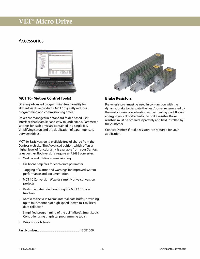
MCT 10 (Motion Control Tools)Offering advanced programming functionality for all Danfoss drive products, MCT 10 greatly reduces programming and commissioning times.
Drives are managed in a standard folder-based user interface that’s familiar and easy to understand. Parameter settings for each drive are contained in a single file, simplifying setup and the duplication of parameter sets between drives.
MCT 10 Basic version is available free of charge from the Danfoss web site. The Advanced edition, which offers a higher level of functionality, is available from your Danfoss sales partner. Both versions require an RS485 converter.• On-line and off-line commissioning
• On-board help files for each drive parameter
• Logging of alarms and warnings for improved system performance and documentation
• MCT 10 Conversion Wizards simplify drive conversion projects
• Real-time data collection using the MCT 10 Scope function
• Access to the VLT® Micro’s internal data buffer, providing up to four channels of high speed (down to 1 millisec) data collection
• Simplified programming of the VLT® Micro’s Smart Logic Controller using graphical programming tools
• Drive upgrade tools
Part Number. ..............................................................130B1000
Brake ResistorsBrake resistor(s) must be used in conjunction with the dynamic brake to dissipate the heat/power regenerated by the motor during deceleration or overhauling load. Braking energy is only absorbed into the brake resistor. Brake resistors must be ordered separately and field installed by the customer.
Contact Danfoss if brake resistors are required for your application.
14 1.800.432.6367www.danfossdrives.com
VLT® Micro Drive
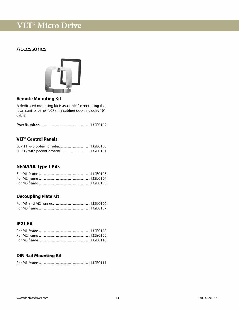
Remote Mounting KitA dedicated mounting kit is available for mounting the local control panel (LCP) in a cabinet door. Includes 10’ cable.
Part Number ...............................................................132B0102
VLT® Control PanelsLCP 11 w/o potentiometer. .....................................132B0100LCP 12 with potentiometer.....................................132B0101
NEMA/UL Type 1 KitsFor M1 frame................................................................132B0103For M2 frame................................................................132B0104For M3 frame................................................................132B0105
Decoupling Plate KitFor M1 and M2 frames..............................................132B0106For M3 frame................................................................132B0107
IP21 KitFor M1 frame................................................................132B0108For M2 frame................................................................132B0109For M3 frame................................................................132B0110
DIN Rail Mounting KitFor M1 frame................................................................132B0111
Accessories