
VLT Common AC Drive Modules
80
ENGINEERING TOMORROW Installation Guide VLT ® Common AC Drive Modules 250–1200 kW vlt-drives.danfoss.com
Transcript of VLT Common AC Drive Modules

ENGINEERING TOMORROW
Installation GuideVLT® Common AC Drive Modules250–1200 kW
vlt-drives.danfoss.com


Contents
1 Introduction 4
1.1 Purpose of the Manual 4
1.2 Additional Resources 4
1.3 Document and Software Version 4
1.4 Approvals and Certifications 4
1.5 Disposal 4
2 Safety 5
2.1 Safety Symbols 5
2.2 Qualified Personnel 5
2.3 Safety Precautions 5
3 Product Overview 7
3.1 Intended Use 7
3.2 Drive Modules 8
3.3 Control Shelf 9
3.4 Wire Harness 9
3.5 DC Fuses 10
4 Mechanical Installation 11
4.1 Receiving and Unpacking the Unit 11
4.1.1 Items Supplied 11
4.1.2 Lifting the Unit 12
4.1.3 Storage 14
4.2 Requirements 14
4.2.1 Environmental 14
4.2.2 Cabinet 14
4.2.3 Bus Bars 14
4.2.4 Cooling and Airflow Requirements 14
4.3 Installing the Drive Modules 15
4.4 Installing the Control Shelf 17
5 Electrical Installation 19
5.1 Safety Instructions 19
5.2 Wiring Diagram 20
5.3 Electrical Requirements for Certifications and Approvals 20
5.3.1 Fuse Selection 20
5.3.1.1 Branch Circuit Protection 21
5.3.1.2 Short-circuit Protection 21
5.3.1.3 Recommended Fuses for CE Compliance 21
Contents Installation Guide
MG37K102 Danfoss A/S © 12/2015 All rights reserved. 1

5.3.1.4 Recommended Fuses for UL Compliance 22
5.4 Electrical Kit Installation 22
5.5 DC Bus Fuse Installation 23
5.6 Motor Connections 23
5.6.1 Motor Cables 23
5.6.1.1 Voltage Rating 23
5.6.1.2 Dimensions 23
5.6.1.3 Length 23
5.6.1.4 Shielding 23
5.6.2 Installing Thermal Protection 24
5.6.2.1 PTC Thermistor 24
5.6.2.2 KTY Sensor 24
5.6.2.3 Brake Resistor Thermal Switch Installation 25
5.6.3 Motor Terminal Connections 25
5.6.3.1 Motor Cable 25
5.6.3.2 Motor Terminal Connections in 2-Drive Module Systems 25
5.6.3.3 Motor Terminal Connections in 4-Drive Module Systems 26
5.7 Mains Input Connections 26
5.7.1 AC Mains Terminal Connections 26
5.7.1.1 Mains Terminal Connections in 2-Drive Module Systems 26
5.7.1.2 Mains Terminal Connections in 4-Drive Module Systems 27
5.7.2 12-Pulse Disconnector Configuration 27
5.7.3 Discharge Resistors 28
5.8 Control Shelf Installation 29
5.9 Control Wiring Connections 29
5.9.1 Control Cable Routing 30
5.9.2 Control Wiring 31
5.9.2.1 Control Terminal Types 31
5.9.2.2 Wiring to Control Terminals 33
5.9.2.3 Enabling Motor Operation (Terminal 27) 33
5.9.2.4 Voltage/Current Input Selection (Switches) 33
5.9.2.5 RS485 Serial Communication 33
5.9.3 Safe Torque Off (STO) 34
5.10 Relay Output 34
5.11 EMC Recommendations 34
5.11.1 Using Shielded Control Cables 36
5.11.2 Grounding of Shielded Control Cables 37
6 Initial Start-up 38
6.1 Pre-start Check List 38
6.2 Safety Instructions 39
Contents VLT® Common AC Drive Modules
2 Danfoss A/S © 12/2015 All rights reserved. MG37K102
6.3 Applying Power 39
6.4 Configuring the Drive System 39
6.5 Testing the Motor Operation 40
7 Specifications 41
7.1 Power-dependent Specifications 41
7.1.1 VLT® HVAC Drive FC 102 41
7.1.2 VLT® AQUA Drive FC 202 45
7.1.3 VLT® AutomationDrive FC 302 50
7.2 Mains Supply to Drive Module 55
7.3 Motor Output and Motor Data 55
7.4 12-Pulse Transformer Specifications 55
7.5 Ambient Conditions for Drive Modules 55
7.6 Cable Specifications 56
7.7 Control Input/Output and Control Data 56
7.8 Kit Dimensions 60
7.8.1 Drive Module 60
7.8.2 Terminal Dimensions 61
7.8.3 DC Bus Dimensions 62
7.9 Fastener Tightening Torques 62
7.9.1 Tightening Torques for Terminals 62
8 Appendix 63
8.1 Symbols, Abbreviations, and Conventions 63
8.2 Block Diagrams 64
Index 75
Contents Installation Guide
MG37K102 Danfoss A/S © 12/2015 All rights reserved. 3

1 Introduction
1.1 Purpose of the Manual
This manual is intended to provide requirements formechanical and electrical installation of the VLT® CommonAC Drive Modules basic kit. Separate installationinstructions for optional components – bus bars and back-channel cooling – are provided with those kits.
This guide includes information on:• Wiring of mains and motor connections.
• Wiring of control and serial communications.
• Control terminal functions.
• Detailed tests that must be performed beforestart-up.
• Initial programming to verify proper functioningof the drive system.
The installation guide is intended for use by qualifiedpersonnel.
To install the drive modules and paralleling kit safely andprofessionally, read and follow the installation guide. Payparticular attention to the safety instructions and generalwarnings. Always keep this installation guide with thepanel containing the VLT® Common AC Drive Modulescomponents.
VLT® is a registered trademark.
1.2 Additional Resources
Other resources are available to understand functions andprogramming of the VLT® Common AC Drive Modules.
• The VLT® Common AC Drive Modules Design Guidecontains detailed information about thecapabilities and functionality of motor controlsystems using these drive modules, and providesguidance for designing this type of system.
• The VLT® Common AC Drive Modules User Guidecontains detailed procedures for start up, basicoperational programming, and functional testing.Additional information describes the userinterface, application examples, troubleshooting,and specifications.
• Refer to the Programming Guide applicable to theparticular series of VLT® Common AC DriveModules used in creating the drive system. Theprogramming guide describes in greater detailhow to work with parameters and providesautomation application examples.
• The VLT® FC Series, D-frame Service Manualcontains detailed service information, includinginformation applicable to the VLT® Common ACDrive Modules.
• The VLT® Common AC Drive Modules DC FusesInstallation Instructions contains detailedinformation about installing the DC fuses.
• The VLT® Common AC Drive Modules Bus Bar KitInstallation Instructions contains detailedinformation about installing the bus bar kit.
• The VLT® Common AC Drive Modules Duct KitInstallation Instructions contains detailedinformation about installing the duct kit.
Refer to other supplemental publications and manuals,available from Danfoss. See vlt-drives.danfoss.com/support/technical-documentation/ for listings.
1.3 Document and Software Version
This manual is regularly reviewed and updated. Allsuggestions for improvement are welcome. Table 1.1 showsthe document version and the corresponding softwareversion.
Edition Remarks Software version
MG37K1xx Original release 7.5x
Table 1.1 Document and Software Version
1.4 Approvals and Certifications
Table 1.2 Approvals
1.5 Disposal
Do not dispose of equipment containingelectrical components together withdomestic waste.Collect it separately in accordance withlocal and currently valid legislation.
Introduction VLT® Common AC Drive Modules
4 Danfoss A/S © 12/2015 All rights reserved. MG37K102
11
2 Safety
2.1 Safety Symbols
The following symbols are used in this manual:
WARNINGIndicates a potentially hazardous situation that couldresult in death or serious injury.
CAUTIONIndicates a potentially hazardous situation that couldresult in minor or moderate injury. It can also be used toalert against unsafe practices.
NOTICEIndicates important information, including situations thatcan result in damage to equipment or property.
2.2 Qualified Personnel
Correct and reliable transport, storage, and installation arerequired for the trouble-free and safe operation of theVLT® Common AC Drive Modules. Only qualified personnelare allowed to install this equipment.
Qualified personnel are defined as trained staff, who areauthorized to install equipment, systems, and circuits inaccordance with pertinent laws and regulations. Also, thepersonnel must be familiar with the instructions and safetymeasures described in this document.
2.3 Safety Precautions
WARNINGHIGH VOLTAGEThe drive system contains high voltage when connectedto AC mains input. Failure to ensure that only qualifiedpersonnel perform the installation can result in death orserious injury.
WARNINGUNINTENDED STARTWhen the drive system is connected to AC mains, themotor can start at any time. Unintended start duringprogramming, service, or repair work can result in death,serious injury, or property damage. The motor can startvia an external switch, a fieldbus command, an inputreference signal from the LCP, a cleared fault condition,or remote operation using MCT 10 software.
To prevent unintended motor start:• Disconnect the drive system from AC mains.
• Press [Off/Reset] on the LCP, beforeprogramming parameters.
• The drive system, motor, and any drivenequipment must be fully wired and assembledwhen the drive is connected to AC mains.
WARNINGDISCHARGE TIMEThe drive module contains DC-link capacitors. Oncemains power has been applied to the drive, thesecapacitors can remain charged even after the power hasbeen removed. High voltage can be present even whenthe warning indicator lights are off. Failure to wait 20minutes after power has been removed beforeperforming service or repair work, can result in death orserious injury.
• Stop the motor.
• Disconnect AC mains and remote DC-linksupplies, including battery back-ups, UPS, andDC-link connections to other drives.
• Disconnect or lock the PM motor.
• Wait 20 minutes for the capacitors to dischargefully before performing any service or repairwork.
Safety Installation Guide
MG37K102 Danfoss A/S © 12/2015 All rights reserved. 5
2 2

WARNINGLEAKAGE CURRENT HAZARD (>3.5 mA)Leakage currents exceed 3.5 mA. Failure to ground thedrive system properly can result in death or seriousinjury. Follow national and local codes regardingprotective earthing of equipment with a leakage current>3.5 mA. Frequency converter technology implies highfrequency switching at high power. This switchinggenerates a leakage current in the ground connection. Afault current in the drive system at the output powerterminals sometimes contain a DC component, which cancharge the filter capacitors and cause a transient groundcurrent. The ground leakage current depends on varioussystem configurations including RFI filtering, shieldedmotor cables, and drive system power.If the leakage current exceeds 3.5 mA, EN/IEC 61800-5-1(Power Drive System Product Standard) requires specialcare.
Grounding must be reinforced in 1 of the following ways:• Ensure the correct grounding of the equipment
by a certified electrical installer.
• Ground wire of at least 10 mm2 (6 AWG).
• Two separate ground wires, both complyingwith the dimensioning rules.
See EN 60364-5-54 § 543.7 for further information.
WARNINGEQUIPMENT HAZARDContact with rotating shafts and electrical equipmentcan result in death or serious injury.
• Ensure that only trained and qualified personnelperform the installation.
• Ensure that electrical work conforms to nationaland local electrical codes.
• Follow the procedures in this document.
CAUTIONPOTENTIAL HAZARD IN THE EVENT OFINTERNAL FAILUREThere is a risk of personal injury when the drive modulesare not properly closed.
• Before applying power, ensure that all safetycovers are in place and securely fastened.
WARNINGHEAVY LOADUnbalanced loads can fall and loads can tip over. Failureto take proper lifting precautions increases risk of death,serious injury, or equipment damage.
• Never walk under suspended loads.
• To guard against injury, wear personalprotective equipment such as gloves, safetyglasses, and safety shoes.
• Be sure to use lifting devices with theappropriate weight rating. The lifting bar mustbe able to handle the weight of the load.
• The load’s center of gravity may be in anunexpected location. Failure to locate the centerof gravity correctly, and position the loadaccordingly before lifting the load, can causethe unit to fall over or tilt unexpectedly duringlifting and transport.
• The angle from the top of the drive module tothe lifting cables has an impact on themaximum load force on the cable. This anglemust be 65° or greater. Attach and dimensionthe lifting cables properly.
WARNINGUNINTENDED MOTOR ROTATIONWINDMILLINGUnintended rotation of permanent magnet motorscreates voltage and can charge the capacitors in thedrive system, resulting in death, serious injury, orequipment damage.
• Ensure that permanent magnet motors areblocked to prevent unintended rotation.
WARNINGDISCONNECT POWER BEFORE SERVICINGSometimes during installation, AC mains power isapplied but then must be disconnected to change theline connections. Failure to follow these steps can resultin death or serious injury.
• Disconnect the frequency converters from theAC mains, 230 V supply, and motor lines.
• After the lines have been disconnected, wait 20minutes for the capacitors to discharge.
Safety VLT® Common AC Drive Modules
6 Danfoss A/S © 12/2015 All rights reserved. MG37K102
22

3 Product Overview
3.1 Intended Use
A frequency converter is an electronic motor controller that uses 1 or more drive modules to convert AC mains input into avariable AC waveform output. The frequency and voltage of the output are regulated to control the motor speed or torque.The frequency converter varies the motor speed based on system feedback, such as position sensors on a conveyor belt.The frequency converter also regulates the motor in response to remote commands from external controllers.
The VLT® Common AC Drive Modules basic kit described in this guide is UL 508 C compliant. The kit is used to create drivesystems of 2 or 4 drive modules. These drive modules are based on the D4h frequency converter and can provide a greaterpower range in a smaller enclosure. The basic kit is designed to allow the flexibility to either order components throughDanfoss or fabricate custom components.
The basic kit contains the following components:• Drive modules
• Control shelf
• Wire harnesses
- Ribbon cable with 44-pin connector (on both ends of the cable)
- Relay cable with 16-pin connector (on 1 end of the cable)
- DC fuse microswitch cable with 2-pin connectors (on 1 end of the cable)
• DC fuses
Other components, such as bus bar kits and back-channel cooling duct kits, are available to customize the drive system.
Product Overview Installation Guide
MG37K102 Danfoss A/S © 12/2015 All rights reserved. 7
3 3

3.2 Drive Modules
Each drive module has an IP00 protection rating. Either 2 or 4 drive modules can be connected in parallel to create a drivesystem, based on power requirements.
130B
E561
.11
2
3
4
1
5
6
7
8
9
12
13
11
10
1 DC-link terminal and DC fuse 8 Ground terminals
2 MDCIC plug 9 Top fan
3 Microswitch to DC fuse 10 Drive module label. See Illustration 4.2.
4 Relays 1 and 2 11 Motor output terminals
5 Brake fault jumper and connector 12 Heat sink and heat sink fan
6 Mains input terminals 13 Ground plate
7 Enclosure door vents – –
Illustration 3.1 Drive Module Overview
Product Overview VLT® Common AC Drive Modules
8 Danfoss A/S © 12/2015 All rights reserved. MG37K102
33

3.3 Control Shelf
The control shelf contains the LCP, MDCIC, and control card. The LCP provides access to the system parameters. The MDCICis connected to each of the drive modules via a ribbon cable and communicates to the control card. The control cardcontrols the operation of the drive modules.
130B
E597
.10
1
2
3
5
6
7
4
1 LCP cradle 5 44-pin cables from MDCIC board to drive modules
2 Control card (underneath cover) 6 MDCIC card
3 Control terminal blocks 7 Control shelf
4 Top-level drive system label. See Illustration 4.1. – –
Illustration 3.2 Control Shelf
3.4 Wire Harness
The VLT® Common AC Drive Modules basic kit contains the following wire harnesses:
• Ribbon cable with 44-pin connector (on both ends of the cable)
• Relay cable with 16-pin connector (on 1 end of the cable)
• DC fuse microswitch cable with 2-pin connectors (on 1 end of the cable)
Product Overview Installation Guide
MG37K102 Danfoss A/S © 12/2015 All rights reserved. 9
3 3
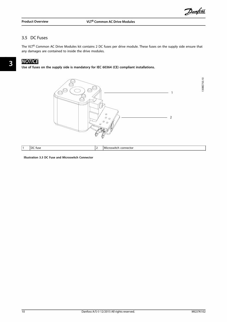
3.5 DC Fuses
The VLT® Common AC Drive Modules kit contains 2 DC fuses per drive module. These fuses on the supply side ensure thatany damages are contained to inside the drive modules.
NOTICEUse of fuses on the supply side is mandatory for IEC 60364 (CE) compliant installations.
130B
E750
.10
1
2
1 DC fuse 2 Microswitch connector
Illustration 3.3 DC Fuse and Microswitch Connector
Product Overview VLT® Common AC Drive Modules
10 Danfoss A/S © 12/2015 All rights reserved. MG37K102
33

4 Mechanical Installation
4.1 Receiving and Unpacking the Unit
4.1.1 Items Supplied
• Make sure the items supplied and the informationon the labels correspond to the order.
- Top-level drive system. This label isfound on the control shelf, lower rightside of the LCP. See Illustration 3.2.
- Drive module. This label is found insidethe drive module enclosure, on the rightside panel. See Illustration 3.1.
• Visually check the packaging and the VLT®
Common AC Drive Modules components fordamage caused by inappropriate handling duringshipment. File any claim for damage with thecarrier. Retain damaged parts, in case clarificationis needed.
130B
E710
.10
OUT: 3x0-Vin 0-800Hz 1460/1380 AIN: 3x380-500V 50/60Hz 1422/1344 A800 kW/1200 HP, High Overload
OUT: 3x0-Vin 0-800Hz 1720/1530AIN: 3x380-500V 50/60Hz 1675/1490 A 1000 kW/1350 HP, Normal Overload
VLT
ASSEMBLED IN USA
T/C: FC-302N800T5E00P2BGC7XXSXXXXAXBXCXXXXDXP/N: 178N0152 S/N: 000101H445
CAUTION:
Stored charge, wait 20 min.Charge residuelle, attendez 20
See manual for special condition/ mains fuseVoir manuel de conditions speciales/fusibles
WARNING:
R AutomationDrivewww.danfoss.com
`
`
1
2
4
5
6
7
3
Max Tamb. 45˚ C/113˚ F w/Output Current Derating Tamb. 40˚ C/104˚ F at Full Output Current CHASSIS (OPEN TYPE) / IP00
SCCR 100 kA at 380-500 V
Listed 36U0 E70524 Ind. Contr. Eq.
1 Type code
2 Code number
3Serial number (last 3 digits indicate the week and yearthat the unit was built, for example 384 = week 38 of2014)
4 Power rating
5 Input voltage, frequency, and current
6 Output voltage, frequency, and current
7 Discharge time
Illustration 4.1 Top-level Drive System Label (Example)
130B
E711
.10
OUT: 3x0-Vin 0-800Hz 480/443 AIN: 3x380-500V 50/60Hz 463/427 A250 kW/350 HP, High Overload
OUT: 3x0-Vin 0-800Hz 588/535 AIN: 3x380-500V 50/60Hz 567/516 A 315 kW/450 HP, Normal Overload
VLT
ASSEMBLED IN USA
T/C: FC-BDMN250T5E00H2SXC7XXSXXXXAXBXCXXXXDXP/N: 178N0025 S/N:
CAUTION:
Stored charge, wait 20 min.Charge residuelle, attendez 20
See manual for special condition/ mains fuseVoir manuel de conditions speciales/fusibles
WARNING:
R AutomationDrivewww.danfoss.com
`
`
Max Tamb. 45˚ C/113˚ F w/Output Current Derating Tamb. 40˚ C/104˚ F at Full Output Current CHASSIS (OPEN TYPE) / IP00
SCCR 100 kA at 380-500 V
1
2
3
4
5
6
Listed 36U0 E70524 Ind. Contr. Eq.
1 Type code
2 Code number
3 Power rating
4 Input voltage, frequency, and current
5 Output voltage, frequency, and current
6 Discharge time
Illustration 4.2 Drive Module Label (Example)
NOTICELOSS OF WARRANTYRemoving the labels from the VLT® Common AC DriveModules can result in loss of warranty.
Mechanical Installation Installation Guide
MG37K102 Danfoss A/S © 12/2015 All rights reserved. 11
4 4

Receiving and unloading• I-beam and hooks rated to lift a drive module having a weight of 125 kg (275 lb), with the necessary safety
margins.
• Crane or other lifting aid rated to lift the minimum weight specified in the documentation package supplied withthe drive module.
• Crowbar to disassemble the wooden shipping container.
Installation• Drill with 10 mm or 12 mm drill bits.
• Tape measurer.
• Screwdriver.
• Wrench with relevant metric sockets (7–17 mm).
• Wrench extensions.
• Torx T50 tool.
Cabinet ConstructionAcquire the tools necessary for assembly of the panel – according to the design plans and established practices.
4.1.2 Lifting the Unit
For measurements and center of gravity, see chapter 7.8 Kit Dimensions.
• Ensure that the lifting device is suitable for the task.
• Move the unit using a hoist, crane, or forklift with the appropriate rating.
• Always use the dedicated lifting eye bolts.
CAUTIONHEAVY LOADUnbalanced loads can fall and loads can tip over. Failure to take proper lifting precautions increases risk of death,serious injury, or equipment damage.
• Never walk under suspended loads.
• To guard against injury, wear personal protective equipment such as gloves, safety glasses, and safety shoes.
• Be sure to use lifting devices with the appropriate weight rating. The lifting bar must be able to handle theweight of the load.
• The load’s center of gravity may be in an unexpected location. Failure to locate the center of gravity correctlyand position the load accordingly before lifting the load can cause the unit to fall over or tilt unexpectedlyduring lifting and transport.
• The angle from the top of the drive module to the lifting cables has an impact on the maximum load force onthe cable. This angle must be 65° or greater. Attach and dimension the lifting cables properly.
Mechanical Installation VLT® Common AC Drive Modules
12 Danfoss A/S © 12/2015 All rights reserved. MG37K102
44

130B
E566
.10
65° min
Illustration 4.3 Lifting the Drive Module
Mechanical Installation Installation Guide
MG37K102 Danfoss A/S © 12/2015 All rights reserved. 13
4 4

4.1.3 Storage
Store the kit in a dry location. Keep the equipment sealedin its packaging until installation. Refer tochapter 7.5 Ambient Conditions for Drive Modules forrecommended ambient conditions.
4.2 Requirements
4.2.1 Environmental
Refer to chapter 7.5 Ambient Conditions for Drive Modulesfor information on required operating temperature,humidity, and other environmental conditions.
For information on the heat dissipation, refer tochapter 7.1 Power-dependent Specifications. For requiredcooling air, refer to chapter 4.2.4 Cooling and AirflowRequirements.
4.2.2 Cabinet
The kit consists of either 2 or 4 drive modules, dependingon the power rating. The cabinets have to meet thefollowing minimum requirements:
Width [mm (in)] 2-drive: 800 (31.5), 4-drive: 1600 (63)
Depth [mm (in)] 600 (23.6)
Height [mm (in)] 2000 (78.7)1
Weight capacity[kg (lb)]
2-drive: 450 (992), 4-drive: 910 (2006)
Ventilation openings See chapter 4.2.4 Cooling and AirflowRequirements.
Table 4.1 Cabinet Requirements
1) Required if Danfoss bus bar or cooling kits are used.
4.2.3 Bus Bars
For terminal dimensions for creating bus bars, refer tochapter 7.8.2 Terminal Dimensions and chapter 7.8.3 DC BusDimensions.
Description Width [mm (in)] Thickness [mm (in)]
AC motor 143.6 (5.7) 6.4 (0.25)
AC mains 143.6 (5.7) 6.4 (0.25)
DC bus 76.2 (3.0) 12.7 (0.50)
Table 4.2 Bus Bar Cross-section Measurements
NOTICETo allow the maximum flow of cooling air, align bus barsvertically.
4.2.4 Cooling and Airflow Requirements
The recommendations provided in this section arenecessary for effective cooling of the drive modules withinthe panel enclosure. Waste heat is removed through acombination of back-channel cooling and fans mounted onthe top of the drive module and in the cabinet.
NOTICEMake sure that the total flow of the cabinet fans meetsthe recommended airflow.
Drive module cooling fansThe drive module is equipped with a heat sink fan, whichprovides the required flow rate of 840 m3/h (500 cfm)across the heat sink. Also, there is a cooling fan mountedon the top of the unit, and a small 24 V DC mixing fanmounted under the input plate that operates any time thedrive module is powered on.
In each drive module, the power card provides DC voltageto power the fans. The mixing fan is powered by 24 V DCfrom the main switch mode power supply. The heat sinkfan and the top fan are powered by 48 V DC from adedicated switch mode power supply on the power card.Each fan has a tachometer feedback to the control card toconfirm that the fan is operating correctly. On/off andspeed control of the fans is provided to reduceunnecessary acoustical noise and extend the life of thefans.
Cabinet fansWith back-channel cooling, 1 or more fans may bemounted in the cabinet to remove waste heat notcontained by the back channel, and any additional heatgenerated by other components inside the enclosure.When back-channel cooling and its associated ducts arenot used, fans mounted in the cabinet must remove all theheat generated inside the enclosure.
For each enclosure housing 2 drive modules, the cabinetfan flow recommendation is as follows:
• When back-channel cooling is used, therecommended flow of the cabinet fans is680 m3/h (400 cfm).
• When back-channel cooling is not used, therecommended total flow of the cabinet fans is4080 m3/h (2400 cfm).
Mechanical Installation VLT® Common AC Drive Modules
14 Danfoss A/S © 12/2015 All rights reserved. MG37K102
44

130B
E569
.10
Illustration 4.4 Airflow, Standard Unit (left) and with Back-channel Cooling Kit (right)
4.3 Installing the Drive Modules
Install the drive modules into the cabinet frame as described in the following steps.
1. Unpack the drive modules from the packaging. See chapter 4.1 Receiving and Unpacking the Unit.
2. Install 2 eye bolts in the top of the first drive module. Prepare the drive module for lifting, using an appropriatelifting harness and an overhead hoist or crane with the necessary lifting capacity. See chapter 4.1.2 Lifting the Unit.
130B
E571
.10
Illustration 4.5 Installation of Eye Bolts
Mechanical Installation Installation Guide
MG37K102 Danfoss A/S © 12/2015 All rights reserved. 15
4 4

3. Install the 2 bottom mounting bolts and gaskets onto the backplate.
4. Using the crane or hoist, lift the drive module and then lower the unit through the top of the cabinet frame. Alignthe bottom mounting holes of the unit with the 2 bottom mounting bolts on the backplate.
5. Verify that the drive module is correctly aligned on the backplate and then secure the bottom of the unit to thebackplate with the 2 hex nuts. See Illustration 4.6. Torque the hex nuts. Refer to chapter 7.9 Fastener TighteningTorques.
6. Secure the top of the unit to the backplate with M10x26 bolts, and then torque the bolts.
7. Install the next drive module.
130B
E572
.10
Illustration 4.6 Installation of Bottom Mounting Bolts
Mechanical Installation VLT® Common AC Drive Modules
16 Danfoss A/S © 12/2015 All rights reserved. MG37K102
44

4.4 Installing the Control Shelf
Install the control shelf assembly as follows:
NOTICETo avoid RFI, do not route control wiring together with power cables or bus bars.
1. Remove the control shelf assembly from its package.
2. Remove the LCP from the control shelf.
3. Install the control shelf mounting brackets on the cabinet frame. Ensure that the brackets are mounted at thecorrect height.
4. Install the control shelf assembly onto the mounting brackets. See Illustration 4.7.
5. Remove the MDCIC cover from the control shelf assembly.
6. Connect the 44-pin ribbon cables from the MDCIC card to the top of the drive modules, following the sequencenumbers indicated next to the connectors on the MDCIC.
7. Route the 44-pin ribbon cables inside the cabinet.
8. Connect the external brake fault wiring harness between the microswitch terminals and the brake jumperconnector on the top of the drive module.
9. Connect the relay wiring between relay 1 or 2 on the control shelf and the corresponding relay connector on thetop of the drive module.
10. Connect the microswitch to the microswitch connector provided on the top of the drive module. Refer toIllustration 3.3.
Mechanical Installation Installation Guide
MG37K102 Danfoss A/S © 12/2015 All rights reserved. 17
4 4

130B
E713
.10
Illustration 4.7 Control Shelf Installation
Mechanical Installation VLT® Common AC Drive Modules
18 Danfoss A/S © 12/2015 All rights reserved. MG37K102
44
5 Electrical Installation
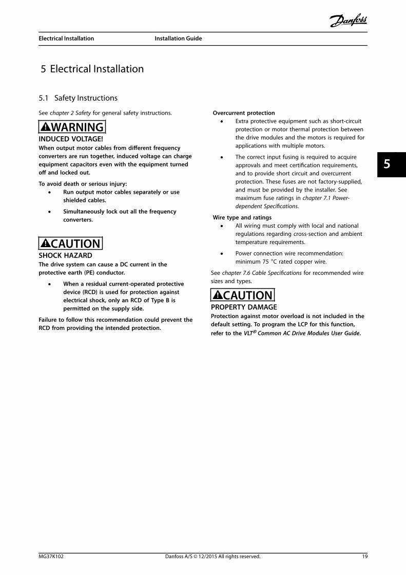
5.1 Safety Instructions
See chapter 2 Safety for general safety instructions.
WARNINGINDUCED VOLTAGE!When output motor cables from different frequencyconverters are run together, induced voltage can chargeequipment capacitors even with the equipment turnedoff and locked out.
To avoid death or serious injury:• Run output motor cables separately or use
shielded cables.
• Simultaneously lock out all the frequencyconverters.
CAUTIONSHOCK HAZARDThe drive system can cause a DC current in theprotective earth (PE) conductor.
• When a residual current-operated protectivedevice (RCD) is used for protection againstelectrical shock, only an RCD of Type B ispermitted on the supply side.
Failure to follow this recommendation could prevent theRCD from providing the intended protection.
Overcurrent protection• Extra protective equipment such as short-circuit
protection or motor thermal protection betweenthe drive modules and the motors is required forapplications with multiple motors.
• The correct input fusing is required to acquireapprovals and meet certification requirements,and to provide short circuit and overcurrentprotection. These fuses are not factory-supplied,and must be provided by the installer. Seemaximum fuse ratings in chapter 7.1 Power-dependent Specifications.
Wire type and ratings• All wiring must comply with local and national
regulations regarding cross-section and ambienttemperature requirements.
• Power connection wire recommendation:minimum 75 °C rated copper wire.
See chapter 7.6 Cable Specifications for recommended wiresizes and types.
CAUTIONPROPERTY DAMAGEProtection against motor overload is not included in thedefault setting. To program the LCP for this function,refer to the VLT® Common AC Drive Modules User Guide.
Electrical Installation Installation Guide
MG37K102 Danfoss A/S © 12/2015 All rights reserved. 19
5 5

5.2 Wiring Diagram
230 VAC50/60 Hz
TB6 Contactor
1
2
Brake Temp (NC)
(optional)
91 (L1)92 (L2)93 (L3)
PE
88 (-)89 (+)
50 (+10 V OUT)
53 (A IN)
54 (A IN)
55 (COM A IN)
0/4-20 mA
12 (+24 V OUT)
13 (+24 V OUT)
18 (D IN)
20 (COM D IN)
15 mA 200 mA
(U) 96(V) 97
(W) 98(PE) 99
(COM A OUT) 39
(A OUT) 42 0/4-20 mA
03
+10 VDC
0 VDC - 10 VDC0/4-20 mA
24 VDC
02
01
05
04
06240 VAC, 2A
24 V (NPN) 0 V (PNP)
0 V (PNP)24 V (NPN)
19 (D IN)
24 V (NPN) 0 V (PNP)27
24 V
0 V
(D IN/OUT)
0 V (PNP)24 V (NPN)
(D IN/OUT)
0 V
24 V29
24 V (NPN) 0 V (PNP)
0 V (PNP)24 V (NPN)
33 (D IN)
32 (D IN)
12
ON
A53 U-I (S201)
ON2
1A54 U-I (S202)ON=0-20 mAOFF=0-10 V
95
400 VAC, 2AP 5-00
(R+) 82
(R-) 81+ - + -
(P RS-485) 68
(N RS-485) 69
(COM RS-485) 61
0 V
5 V
S801
RS-485RS-485
21 O
N
S801/Bus Term.OFF-ON
3-phasepowerinput
Load Share Switch ModePower Supply
Motor
Analog Output
Interface
Relay1
Relay2
ON=TerminatedOFF=Open
Brakeresistor
(NPN) = Sink(PNP) = Source
==
=
240 VAC, 2A
400 VAC, 2A0 VDC - 10 VDC
10 VDC
37 (D IN) - option
130B
E752
.10
Illustration 5.1 Wiring Diagram
5.3 Electrical Requirements for Certifications and Approvals
5.3.1 Fuse Selection
It is recommended to use fuses and/or circuit breakers at the mains supply side as protection if a breakdown of 1 or moreinternal components of the drive module occur.
NOTICEThe use of fuses and/or circuit breakers is mandatory to ensure compliance with CE IEC 60364 or UL NEC2009.
Electrical Installation VLT® Common AC Drive Modules
20 Danfoss A/S © 12/2015 All rights reserved. MG37K102
55

5.3.1.1 Branch Circuit Protection
To protect the installation against electrical and fire hazards, protect all branch circuits in an installation, for example inswitch gear and machines, against short circuit and overcurrent according to national and international regulations.
5.3.1.2 Short-circuit Protection
Danfoss recommends the fuses listed in chapter 5.3.1.3 Recommended Fuses for CE Compliance andchapter 5.3.1.4 Recommended Fuses for UL Compliance to achieve CE or UL compliance in the protection of service personneland property against the consequences of component breakdown in the drive modules.
5.3.1.3 Recommended Fuses for CE Compliance
Drivemodules
insystem
FC 302modules
[kW]
FC 102and FC
202modules
[kW]
Recommendedfuse
Recommendedfuse
(maximum)
2 N250 N315 aR-630 aR-630
2 N315 N355 aR-630 aR-630
2 N355 N400 aR-630 aR-630
2 N400 N450 aR-800 aR-800
2 N450 N500 aR-800 aR-800
4 N500 N560 aR-900 aR-900
4 N560 N630 aR-900 aR-900
4 N630 N710 aR-1600 aR-1600
4 N710 N800 aR-1600 aR-1600
4 N800 N1M0 aR-1600 aR-1600
Table 5.1 12-Pulse Drive Systems (380–500 V AC)
Drivemodules
insystem
FC 302modules
[kW]
FC 102and FC
202modules
[kW]
Recommendedfuse
Recommendedfuse
(maximum)
2 N450 N500 aR-1600 aR-1600
4 N500 N560 aR-2500 aR-2500
4 N560 N630 aR-2500 aR-2500
4 N630 N710 aR-2500 aR-2500
4 N710 N800 aR-2500 aR-2500
4 N800 N1M0 aR-2500 aR-2500
Table 5.2 6-Pulse Drive Systems (380–500 V AC)
Drivemodules
insystem
FC 302modules
[kW]
FC 102and FC
202modules
[kW]
Recommendedfuse
Recommendedfuse
(maximum)
2 N250 N315 aR-550 aR-550
2 N315 N355 aR-630 aR-630
2 N355 N400 aR-630 aR-630
2 N400 N500 aR-630 aR-630
2 N500 N560 aR-630 aR-630
2 N560 N630 aR-900 aR-900
4 N630 N710 aR-900 aR-900
4 N710 N800 aR-900 aR-900
4 N800 N900 aR-900 aR-900
4 N900 N1M0 aR-1600 aR-1600
4 N1M0 N1M2 aR-1600 aR-1600
Table 5.3 12-Pulse Drive Systems (525–690 V AC)
Drivemodules
insystem
FC 302modules
[kW]
FC 102and FC
202modules
[kW]
Recommendedfuse
Recommendedfuse
(maximum)
4 N630 N710 aR-1600 aR-1600
4 N710 N800 aR-2000 aR-2000
4 N800 N900 aR-2500 aR-2500
4 N900 N1M0 aR-2500 aR-2500
4 N1M0 N1M2 aR-2500 aR-2500
Table 5.4 6-Pulse Drive Systems (525–690 V AC)
Electrical Installation Installation Guide
MG37K102 Danfoss A/S © 12/2015 All rights reserved. 21
5 5

5.3.1.4 Recommended Fuses for UL Compliance
• The drive modules are supplied with built-in AC fuses. The modules have been qualified for 100 kA short circuitcurrent rating (SCCR) for the standard bus bar configurations at all voltages (380–690 V AC).
• The drive system is qualified for 100 kA SCCR with any Class L or Class T UL-listed fuses connected at the inputterminals of the drive modules, if no power options or extra bus bars are connected externally.
• The current rating of the Class L or Class T fuses should not exceed the listed fuse rating in Table 5.5 to Table 5.8.
Drivemodules in
system
FC 302modules
[kW]
FC 102 and FC202 modules
[kW]
Recommendedfuse (maximum)
2 N250 N315 aR-630
2 N315 N355 aR-630
2 N355 N400 aR-630
2 N400 N450 aR-800
2 N450 N500 aR-800
4 N500 N560 aR-900
4 N560 N630 aR-900
4 N630 N710 aR-1600
4 N710 N800 aR-1600
4 N800 N1M0 aR-1600
Table 5.5 12-Pulse Drive Systems (380–500 V AC)
Any minimum 500 V UL-listed fuse can be used for the 380–500 V ACdrive systems.
Drivemodules in
system
FC 302modules
[kW]
FC 102 and FC202 modules
[kW]
Recommendedfuse (maximum)
2 N450 N500 aR-1600
4 N500 N560 aR-2500
4 N560 N630 aR-2500
4 N630 N710 aR-2500
4 N710 N800 aR-2500
4 N800 N1M0 aR-2500
Table 5.6 6-Pulse Drive Systems (380–500 V AC)
Any minimum 500 V UL-listed fuse can be used for the 380–500 V ACdrive systems.
Drivemodules in
system
FC 302modules
[kW]
FC 102 andFC 202
modules [kW]
Recommendedfuse (maximum)
2 N250 N315 aR-550
2 N315 N355 aR-630
2 N355 N400 aR-630
2 N400 N500 aR-630
2 N500 N560 aR-630
2 N560 N630 aR-900
4 N630 N710 aR-900
4 N710 N800 aR-900
4 N800 N900 aR-900
4 N900 N1M0 aR-1600
4 N1M0 N1M2 aR-1600
Table 5.7 12-Pulse Drive Systems (525–690 V AC)
Any minimum 700 V UL-listed fuse can be used for the 525–690 V ACdrive systems.
Drivemodules in
system
FC 302modules
[kW]
FC 102 and FC202 modules
[kW]
Recommendedfuse (maximum)
4 N630 N710 aR-1600
4 N710 N800 aR-2000
4 N800 N900 aR-2500
4 N900 N1M0 aR-2500
4 N1M0 N1M2 aR-2500
Table 5.8 6-Pulse Drive Systems (525–690 V AC)
Any minimum 700 V UL-listed fuse can be used for the 525–690 V ACdrive systems.
5.4 Electrical Kit Installation
This section describes how the electrical kit is used to connect 2 or 4 drive modules in parallel – to provide controlledpower to an AC motor. A diagram is provided for each of the 4 configurations which, if followed, meet specific agencyapprovals and certifications. If designing and building other configurations, seek agency approvals or certifications apartfrom Danfoss.
Read the following section for guidance in making electrical connections when assembling the drive modules into a panel.
Electrical Installation VLT® Common AC Drive Modules
22 Danfoss A/S © 12/2015 All rights reserved. MG37K102
55
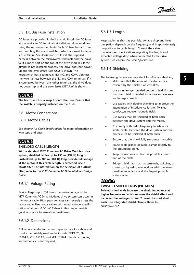
5.5 DC Bus Fuse Installation
DC fuses are provided in the basic kit. Install the DC fusesat the available DC terminals at individual drive modules,using the recommended bolts. Each DC fuse has a fixturefor mounting the micro switches, which are used to detecta fuse failure. See Illustration 3.3. Install the suppliedharness between the microswitch terminals and the brakefault jumper port on the top of the drive modules. If thejumper is not installed properly, the drive does not powerup and the error Brake IGBT Fault is shown. Themicroswitch has 3 terminals: NO, NC, and COM. Connectthe wire harness between the NC and COM terminals. If itis connected between any other terminals, the drive doesnot power up, and the error Brake IGBT Fault is shown.
NOTICEThe Microswitch is a snap fit onto the fuse. Ensure thatthe switch is properly installed on the fuses.
5.6 Motor Connections
5.6.1 Motor Cables
See chapter 7.6 Cable Specifications for more information onwire type and sizes.
NOTICESHIELDED CABLE LENGTHWith a standard VLT® Common AC Drive Modules drivesystem, shielded cables up to 150 m (492 ft) long orunshielded up to 300 m (984 ft) long provide full voltageat the motor. If this cable length is exceeded, use adU/dt filter. For information on the selection of a dU/dtfilter, refer to the VLT® Common AC Drive Modules DesignGuide.
5.6.1.1 Voltage Rating
Peak voltages up to 2.8 times the mains voltage of theVLT® Common AC Drive Modules drive system can occur inthe motor cable. High peak voltages can severely stress themotor cable. Use motor cables with rated voltage specifi-cation of at least 0.6/1 kV. Cables in this range providegood resistance to insulation breakdown.
5.6.1.2 Dimensions
Follow local codes for current capacity data for cables andconductors. Widely used codes include: NFPA 70, EN60204-1, VDE 0113-1, and VDE 0298-4. Overdimensioningfor harmonics is not required.
5.6.1.3 Length
Keep cables as short as possible. Voltage drop and heatdissipation depends on the frequency and is approximatelyproportional to cable length. Consult the cablemanufacturer specifications regarding the length andexpected voltage drop when connected to the drivesystem. See chapter 7.6 Cable Specifications.
5.6.1.4 Shielding
The following factors are important for effective shielding:• Make sure that the amount of cable surface
covered by the shield is at least 80%.
• Use a single-layer braided copper shield. Ensurethat the shield is braided to reduce surface areafor leakage currents.
• Use cables with double shielding to improve theattenuation of interference further. Twistedconductors reduce magnetic fields.
• Use cables that are shielded at both endsbetween the drive system and the motor.
• To comply with radio frequency interferencelimits, cables between the drive system and themotor must be shielded at both ends.
• Ensure that the shield fully surrounds the cable.
• Route cable glands or cable clamps directly tothe grounding point.
• Keep connections as short as possible at eachend of the cable.
• Bridge shield gaps such as terminals, switches, orcontactors by using connections with the lowestpossible impedance and the largest possiblesurface area.
NOTICETWISTED SHIELD ENDS (PIGTAILS)Twisted shield ends increase the shield impedance athigher frequencies, which reduces the shield effect andincreases the leakage current. To avoid twisted shieldends, use integrated shield clamps. Refer toIllustration 5.2.
Electrical Installation Installation Guide
MG37K102 Danfoss A/S © 12/2015 All rights reserved. 23
5 5

1
2
130B
E747
.10
PE
PEPE
PE
1 Correct grounding of shielded ends
2 Incorrect grounding using twisted shield ends (pigtail)
Illustration 5.2 Example of Shield Ends
5.6.2 Installing Thermal Protection
5.6.2.1 PTC Thermistor
Using a digital input and 10 V supply
PTC / Thermistor R
OFF
ON
<800 Ω
+10V
130B
A15
2.10
>2.7 kΩ
12 13 18 37322719 29 33 20
555039 42 53 54
Illustration 5.3 PTC Thermistor Connection - Digital Input with10 V Supply
Using an analog input and 10 V supply
555039 42 53 54
R<3.0 k Ω>3.0 k Ω
+10V
130B
A15
3.11
PTC / Thermistor
OFF
ON
Illustration 5.4 PTC Thermistor Connection - Analog Input with10 V Supply
Using a digital input and 24 V as supply
PTC / Thermistor
OFF
ON
+24V
12 13 18 3732
A
2719 29 33
B
20
GN
D
R<6.6 k Ω >10.8 k Ω
130B
A15
1.11
Illustration 5.5 PTC Thermistor Connection - Digital Input with24 V Supply
Check that the selected supply voltage follows the specifi-cation of the used thermistor element.
Inputdigital/analog
Supplyvoltage [V]
Trip resistance kΩ Resetresistance
Digital 10 > 2.7 <800 ΩAnalog 10 > 3.0 <3.0 kΩDigital 24 > 10.8 <6.6 kΩ
Table 5.9 PTC Thermistor Resistance Parameters
5.6.2.2 KTY Sensor
FC 302 can handle 3 types of KTY sensors:• KTY Sensor 1: 1 kΩ at 100 °C (for example, Philips
KTY 84–1).
• KTY Sensor 2: 1 kΩ at 25 °C (for example, PhilipsKTY 83–1).
• KTY Sensor 3: 1 kΩ at 25 °C (for example, PhilipsKTY–10).
0
500
1000
1500
2000
2500
3000
3500
4000
4500
-25 0 25 50 75 100 125 150
Temperature [°C]
Res
ista
nce
[Ohm
]
KTY type 1 KTY type 2 KTY type 3
130B
B917
.10
Illustration 5.6 KTY Type Selection
Electrical Installation VLT® Common AC Drive Modules
24 Danfoss A/S © 12/2015 All rights reserved. MG37K102
55

NOTICEPELV COMPLIANCEWhen motor temperature is monitored via a thermistoror KTY sensor, PELV compliance is not achieved if shortcircuits occur between motor windings and the sensor.Ensure that the sensor is isolated better.
5.6.2.3 Brake Resistor Thermal SwitchInstallation
Each drive module has a brake fault jumper connector onthe top plate. This connector has a pre-installed jumper asshown in Illustration 8.3.
The brake fault jumper must always be in place to ensureproper operation of the drive module. Without this jumperconnection, the drive module does not allow the inverterto operate, and a brake IGBT fault is shown.
The brake fault jumper connector is provided forconnection of the Klixon thermal switch on the brakeresistors. The thermal switch is a normally-closed type. Ifthe temperature of the brake resistor exceeds therecommended values, the thermal switch opens. Make theconnection as shown in Illustration 8.5, using 1 mm2
(18 AWG), reinforced and doubly insulated wire.
NOTICEDanfoss is not responsible for the failure of any Klixonthermal switch.
5.6.3 Motor Terminal Connections
WARNINGINDUCED VOLTAGEInduced voltage from output motor cables from differentfrequency converters that are run together can chargeequipment capacitors even with the equipment turnedoff and locked out. Failure to run output motor cablesseparately or use shielded cables could result in death orserious injury.
• Run output motor cables separately.
Or
• Use shielded cables.
• Simultaneously lock out all the frequencyconverters.
• Comply with local and national electrical codesfor cable sizes. For maximum cable sizes, seechapter 7.1 Power-dependent Specifications.
• Follow motor manufacturer wiring requirements.
• Do not wire a starting or pole-changing device(for example, Dahlander motor or slip ring
induction motor) between the drive system andthe motor.
5.6.3.1 Motor Cable
All types of 3-phase asynchronous standard motors can beused with the drive system.
Connect the motor to the following terminals:• U/T1/96
• V/T2/97
• W/T3/98
• Ground to terminal 99
Factory setting is for clockwise rotation with the drivesystem output connected as follows:
Terminal number Function
96 Mains U/T1
97 V/T2
98 W/T3
99 Ground
Table 5.10 Motor Cable Terminals
• Terminal U/T1/96 connectedto U-phase
• Terminal V/T2/97 connectedto V-phase
• Terminal W/T3/98 connectedto W-phase
175H
A03
6.11
U1 V1 W1
96 97 98
FC
MotorU2 V2 W2
U1 V1 W1
96 97 98
FC
MotorU2 V2 W2
Table 5.11 Changing Motor Rotation
The direction of rotation can be changed by switching 2phases in the motor cable, or by changing the setting ofparameter 4-10 Motor Speed Direction.
Motor rotation check can be performed usingparameter 1-28 Motor Rotation Check and following thesteps shown in Table 5.11.
5.6.3.2 Motor Terminal Connections in 2-Drive Module Systems
Illustration 8.9 and Illustration 8.10 show the bus barconnections for 6-pulse and 12-pulse 2-D systems, respec-tively.
Electrical Installation Installation Guide
MG37K102 Danfoss A/S © 12/2015 All rights reserved. 25
5 5

1. There is 1 set of common terminals for the motor.
NOTICEIf it is decided not to use common terminals in theconstruction of a system using 2 drive modules, then usecable quantities in multiples of 2.
2. If there are multiple runs, make sure that thecables are within 10% of one another. Measurebetween the common terminals and the firstcommon point of a phase, normally the motorterminals.
3. Strip a section of the outer cable insulation.
4. Connect the ground wire to the nearestprotective earth terminal.
5. Connect the 3-phase motor wiring to terminalsU/96, V/97, and W/98, using the recommendedbolts. See chapter 7.9.1 Tightening Torques forTerminals.
6. Tighten the motor terminals 19–40 Nm (168–354 in-lb).
5.6.3.3 Motor Terminal Connections in 4-Drive Module Systems
Illustration 8.11 shows the bus bar connections for 4-Dsystem. There is a common terminal in each cabinet. Routethe cables from input terminals 1 and 2 separately to themains terminal. Similarly, cables from motor terminal 1 andmotor terminal 2 should be routed separately andconnected at the motor terminal. The recommended cableruns are in even numbers that must be shared equallybetween the terminals. To ensure equal sharing of currentand for proper operation of the drive modules, the lengthof the cable from terminal 1 should be equal to the lengthof the cable from the terminal 2. The maximum size of thecable is given in chapter 7.1 Power-dependent Specifications.
1. Use cable quantities in multiples of 2 to obtainan equal number of wires attached to bothterminals. Do not use 1 cable.
NOTICEIf it is decided not to use common terminals in theconstruction of a system using 4 drive modules, then usecable quantities in multiples of 4.
2. Make sure that the cables are within 10% of oneanother. Measure between the common terminalsand the first common point of a phase, normallythe motor terminals.
3. Strip a section of the outer cable insulation.
4. Connect the ground wire to the nearestprotective earth (ground) terminal.
5. Connect the 3-phase motor wiring to terminalsU/96, V/97, and W/98, using the recommendedbolts. See chapter 7.9.1 Tightening Torques forTerminals.
6. Tighten the motor terminals 19–40 Nm (168–354 in-lb).
5.7 Mains Input Connections
There are several types of AC mains systems for supplyingpower to frequency converters. Each affects the EMCcharacteristics of the system. The 5-wire TN-S systems areregarded as best regarding EMC, while the isolated ITsystem is the least desirable.
Systemtype
Description
TN MainsSystems
There are 2 types of TN mains distribution systems:TN-S and TN-C.
TN-S A 5-wire system with separate neutral (N) andprotective earth (PE) conductors. It provides thebest EMC properties and avoids transmittinginterference.
TN-C A 4-wire system with a common neutral andprotective earth (PE) conductor throughout thesystem. The combined neutral and PE conductorresults in poor EMC characteristics.
TT MainsSystems
A 4-wire system with a grounded neutralconductor and individual grounding of the drivesystem. It has good EMC characteristics whengrounded properly.
IT GridSystem
An isolated 4-wire system with the neutralconductor either not grounded or grounded via animpedance.
Table 5.12 AC Mains Systems and EMC Characteristics
5.7.1 AC Mains Terminal Connections
When making mains connections, observe the following:• Size the wiring based on the input current of the
frequency converter. For maximum wire sizes, seechapter 7.1 Power-dependent Specifications.
• Comply with local and national electrical codesfor cable sizes.
5.7.1.1 Mains Terminal Connections in 2-Drive Module Systems
Illustration 8.9 and Illustration 8.10 show the bus barconnections for 6-pulse and 12-pulse 2-D systems, respec-tively.
• If there are 12-pulse connections in 2-drivemodule systems, the common terminal isavailable for the motor only. The mains cables areconnected directly to the drive input terminals. In
Electrical Installation VLT® Common AC Drive Modules
26 Danfoss A/S © 12/2015 All rights reserved. MG37K102
55

such a case, an equal number of cables should goto each drive terminal.
• There are individual brake terminals available ineach drive module. Connect an equal number ofrecommended cables to the individual braketerminals.
NOTICETo avoid any current imbalances, the length of theindividual cables must be equal.
1. There is 1 set of common terminals for the mains.
NOTICEIf it is decided not to use common terminals in theconstruction of a system using 2 drive modules, usecable quantities in multiples of 2.
2. In the case of multiple runs, make sure that thecables are within 10% of one another. Measurebetween the common terminals and the firstcommon point of a phase, normally the mainsterminals.
3. For 12-pulse drive modules, the set of cables fromthe 1st drive module connects to the star-secondary winding of the 12-pulse transformer.The set from the 2nd drive module connects tothe delta-secondary winding of the 12-pulsetransformer.
4. Strip a section of the outer cable insulation.
5. Connect the ground wire to the nearest groundterminal.
6. Connect the 3-phase mains wiring to terminalsU/96, V/97, and W/98, using the recommendedbolts. See chapter 7.9.1 Tightening Torques forTerminals.
7. Tighten the mains terminals 19–40 Nm (168–354in-lb).
5.7.1.2 Mains Terminal Connections in 4-Drive Module Systems
Illustration 8.11 shows the bus bar connections for 4-Dsystems.
1. Use cable quantities in multiples of 2 to obtainan equal number of wires attached to bothterminals. Do not use 1 cable.
2. Make sure that the cables are within 10% of oneanother. Measure between the common terminalsand the 1st common point of a phase, which, for6 pulse drive modules, is normally the mainsterminals.
3. For 12-pulse drive modules, the set of cables fromthe 1st cabinet connects to the star-secondarywinding of the 12-pulse transformer. The set from
the 2nd cabinet connects to the delta-secondarywinding of the 12-pulse transformer.
4. Strip a section of the outer cable insulation.
5. Connect the ground wire to the nearest groundterminal.
6. Connect the 3-phase mains wiring to terminalsR/91, S/92, and T/93, using the recommendedbolts. See chapter 7.9.1 Tightening Torques forTerminals.
7. Tighten the motor terminals 8.5–20.5 Nm (75–181in-lb).
5.7.2 12-Pulse Disconnector Configuration
This section describes how to use a disconnector for a 12-pulse drive system. When using disconnectors orcontactors, make sure to install an interlock. Wheninstalled, both contactors or disconnectors should close toavoid 1 set of rectifiers not working. See Illustration 8.1 fora diagram of these connections.
The selected contactors or mains disconnectors shouldhave NC auxiliary contacts routed as shown. Connect theinterlock in series with the Klixon switch of the brake. Ifonly 1 contactor/disconnector has closed, the LCP showsthe error Brake IGBT Fault and does not allow the drivesystem to power the motor. See Illustration 8.2 for adiagram showing a BRF connection with 12-pulse discon-nector and interlock.
NOTICEIf the brake option is not selected, the Klixon switch canbe bypassed.
NOTICEDanfoss is not responsible for any failure or malfunctionin the disconnector/contactor switch.
Electrical Installation Installation Guide
MG37K102 Danfoss A/S © 12/2015 All rights reserved. 27
5 5

5.7.3 Discharge Resistors
There are common positive and negative DC terminals on each drive module. If a shorter time to achieve the reduced runfunctionality is wanted, connect the external discharge resistor for quicker discharge of DC-link voltage. It is possible toconnect a discharge resistor in an additional cabinet, through a contactor. This discharge contactor should have an interlockwith the mains contactor/disconnector’s auxiliary NC contacts, to avoid a discharge when the drive system is powered. SeeIllustration 8.7 for a diagram showing a 4-D system with discharge resistor connections.
Base the selection of a discharge resistor on the energy and power levels given in Table 5.13 for different power sizes, onboth 12-pulse and 6-pulse systems.
FC 102FC 202
N500 N560 N630 N710 N800 N1M0
FC 302 N450 N500 N560 N630 N710 N800
Drive modules required(HO rating)
2xN250 4xN160 4xN200 4xN200 4xN250 4xN250
Resistance required to reduce DCvoltage below 50 V within 300 s
(5 min), Ω
3036 2277 1822 1822 1518 1518
Power rating of resistor (W) 182 242 303 303 363 363
Energy dissipated by resistor (J) 7773 10365 12956 12956 15547 15547
Table 5.13 Discharge Resistors Recommended for Drive Systems with 380–480 V AC Mains Supply
FC 102FC 202
N630 N710 N800 N900 N1M0 N1M2
FC 302 N560 N630 N710 N800 N900 N1M0
Drive modules required(HO rating)
2xN315 4xN200 4xN250 4xN250 4xN315 4xN315
Resistance required to reduce DCvoltage below 50 V within 300 s(5 min), Ω
4571 3047 2285 2285 2285 2285
Power rating of resistor (W) 230 345 459 459 459 459
Energy dissipated by resistor (J) 8819 13229 17638 17638 17638 17638
Table 5.14 Discharge Resistors Recommended for Drive Systems with 525–690 V AC Mains Supply
NOTICEDanfoss is not responsible for any failure or malfunction of the resistor, or for any misconnections made by the installer.
NOTICEThe wire used with the brake resistor should be double-insulated or have reinforced insulation.
Electrical Installation VLT® Common AC Drive Modules
28 Danfoss A/S © 12/2015 All rights reserved. MG37K102
55

5.8 Control Shelf Installation
The control shelf is preassembled. However, verify its various connections against the connection diagram. See Illustration 8.6for a diagram showing the various control shelf connections.
NOTICEINCORRECT CONNECTION ORDERIf the connections are not made in the correct order, the drive modules do not function.
Check the following connections:• Connection of the 44-pin ribbon cable between the MDCIC and the control card.
• When used, Safe Torque Off (STO) jumper connection must be made between the 12th and 27th pins to ensureproper STO operation.
• Connect the 44-pin ribbon cable to the MDCIC connectors in the correct order.
- For systems with 4 drive modules, connect the ribbon cables to inverter 1, inverter 2, inverter 3, and theninverter 4.
- For systems with 2 drive modules, connect the ribbon cables to inverter 1, then inverter 2. Leave inverter3 and inverter 4 terminals unconnected.
• Place the corresponding current scaling card on each respective connector.
- For systems with 4 drive modules, Inv1, Inv2, Inv3, and Inv4.
- For systems with 2 drive modules, Inv1 and Inv2. Leave connectors Inv3 and Inv4 unconnected.
NOTICESCALING CARD POSITIONIf the scaling cards are not placed in the correct order, the drive modules do not function.
• Do not reverse the current scaling card. Check that the PCB spacer is fixed on the MDCIC board.
• Ensure correct installation of the STO relay and the power supply on the DIN rail. Make the connections as shownin Illustration 8.6.
• The external supply (100–230 V) must be available at terminals 1 and 2 on the terminal block.
• Make more checks to ensure that the wiring of the fuse microswitches and the BRF jumpers are properly routed.
• Check that all the screws on the PCBs are secure.
• To ensure proper EMC protection, verify that the MDCIC plate is properly attached to the control shelf assembly.
5.9 Control Wiring Connections
Make sure to use the provided wire pathway when routing the control wires from the bottom of the drive system cabinet tothe control terminal.
Electrical Installation Installation Guide
MG37K102 Danfoss A/S © 12/2015 All rights reserved. 29
5 5
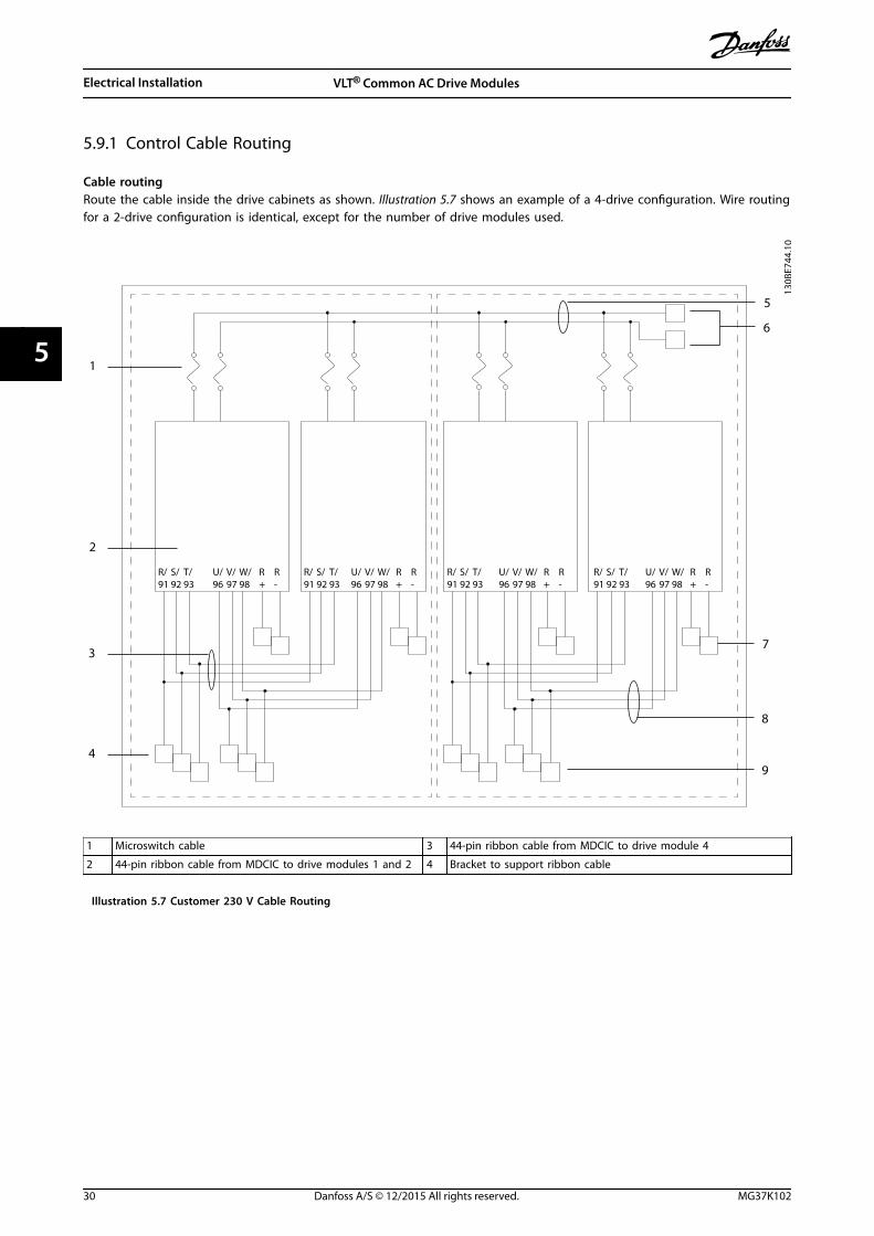
5.9.1 Control Cable Routing
Cable routingRoute the cable inside the drive cabinets as shown. Illustration 5.7 shows an example of a 4-drive configuration. Wire routingfor a 2-drive configuration is identical, except for the number of drive modules used.
130B
E744
.10
R/91
S/92
T/93
U/96
V/97
W/98
R+
R -
R/91
S/92
T/93
U/96
V/97
W/98
R+
R -
R/91
S/92
T/93
U/96
V/97
W/98
R+
R -
R/91
S/92
T/93
U/96
V/97
W/98
R+
R -
1
2
3
4
5
6
7
8
9
1 Microswitch cable 3 44-pin ribbon cable from MDCIC to drive module 4
2 44-pin ribbon cable from MDCIC to drive modules 1 and 2 4 Bracket to support ribbon cable
Illustration 5.7 Customer 230 V Cable Routing
Electrical Installation VLT® Common AC Drive Modules
30 Danfoss A/S © 12/2015 All rights reserved. MG37K102
55

5.9.2 Control Wiring
• Isolate the control wiring from the high-power components in the drive modules.
• When the drive module is connected to a thermistor, ensure that the thermistor control wiring is shielded andreinforced/double insulated. A 24 V DC supply voltage is recommended. See Illustration 5.8.
NOTICEMINIMIZE INTERFERENCETo minimize interference, keep control wires as short as possible and separate them from high-power cables.
The control terminals are on the control shelf, directly below the LCP. The control cable is routed at the bottom of thecabinet.
1. Follow the designated control cable routing as shown in chapter 5.9.1 Control Cable Routing.
2. Tie down all control wires.
3. Ensure optimum electrical immunity by properly connecting the shields.
Fieldbus connectionFor details, see the relevant fieldbus instructions.
1. Follow the designated control cable routing as shown in chapter 5.9.1 Control Cable Routing.
2. Tie down all control wires.
3. Connect the relevant options on the control card.
5.9.2.1 Control Terminal Types
Illustration 5.8 shows the removable frequency converter connectors. Terminal functions and default settings are summarizedin Table 5.15. See Illustration 5.8 for the location of the control terminals within the unit.
130B
E062
.10
2
3
4
1
1 Terminals (+)68 and (-)69 are for an RS485 serial communication connection.
2 USB port available for use with the MCT 10 Set-up Software.
3 2 analog inputs, 1 analog output, 10 V DC supply voltage, and commons for the inputs and output.
4 4 programmable digital inputs terminals, 2 extra digital terminals programmable as either input or output, a 24 V DCterminal supply voltage, and a common for optional customer-supplied 24 V DC voltage.
Illustration 5.8 Control Terminal Locations
Electrical Installation Installation Guide
MG37K102 Danfoss A/S © 12/2015 All rights reserved. 31
5 5

Terminal Parameter Defaultsetting
Description
Digital inputs/outputs
12, 13 – +24 V DC Digital inputs. 24 V DC supplyvoltage. Maximum output currentis 200 mA total for all 24 V loads.Usable for digital inputs andexternal transducers.
18 Parameter 5-10 Terminal 18 Digital Input [8] Start
19 Parameter 5-11 Terminal 19 Digital Input [10] Reversing
32 Parameter 5-14 Terminal 32 Digital Input [0] No operation
33 Parameter 5-15 Terminal 33 Digital Input [0] No operation
27 Parameter 5-12 Terminal 27 Digital Input [2] Coast inverse Selectable for digital input andoutput. Default setting is input.29 Parameter 5-13 Terminal 29 Digital Input [14] Jog
20 – – Common for digital inputs and 0 Vpotential for 24 V supply.
37 – Safe Torque Off (STO) Safe input (optional). Used for STO.
Analog inputs/outputs
39 – – Common for analog outputProgrammable analog output. Theanalog signal is 0–20 mA or 4–
20 mA at a maximum of 500 Ω10 V DC analog supply voltage.15 mA maximum commonly usedfor potentiometer or thermistor.
42 Parameter 6-50 Terminal 42 Output Speed 0 – high limit
50 – +10 V DC
53 Parameter group 6-1* Analog Input 1 Reference Analog input. Selectable forvoltage or current. Switches A53and A54 select mA or V.
54 Parameter group 6-2* Analog Input 2 Feedback
55 – – Common for analog input
Serial communication
61 – – Integrated RC-filter for cable shield.ONLY for connecting the shieldwhen experiencing EMC problems.
68 (+) Parameter group 8-3 FC Port Settings – RS485 Interface. A control cardswitch is provided for terminationresistance.
69 (-) Parameter group 8-3 FC Port Settings –
Relays
01, 02, 03 Parameter 5-40 Function Relay [0] [9] Alarm Form C relay output. Usable for ACor DC voltage and resistive orinductive loads.
04, 05, 06 Parameter 5-40 Function Relay [1] [5] Running
Table 5.15 Terminal Description
Extra terminals:• Two form C relay outputs. Location of the outputs depends on frequency converter configuration.
• Terminals on built-in optional equipment. See the manual provided with the equipment option.
Electrical Installation VLT® Common AC Drive Modules
32 Danfoss A/S © 12/2015 All rights reserved. MG37K102
55

5.9.2.2 Wiring to Control Terminals
Terminal plugs can be removed for easy access.
130B
T306
.10
Illustration 5.9 Removal of Control Terminals
5.9.2.3 Enabling Motor Operation(Terminal 27)
A jumper wire is required between terminal 12 (or 13) andterminal 27 for the frequency converter to operate whenusing factory default programming values.
• Digital input terminal 27 is designed to receive24 V DC external interlock command.
• When no interlock device is used, wire a jumperbetween control terminal 12 (recommended) or13 to terminal 27. The jumper provides aninternal 24 V signal on terminal 27.
• When the status line at the bottom of the LCPreads AUTO REMOTE COAST, it indicates that theunit is ready to operate but is missing an inputsignal on terminal 27.
• When factory installed optional equipment iswired to terminal 27, do not remove that wiring.
5.9.2.4 Voltage/Current Input Selection(Switches)
The analog mains terminals 53 and 54 allow the setting ofthe input signal to voltage (0–10 V) or current (0/4–20 mA). See Illustration 5.8 for the location of the controlterminals within the drive system.
Default parameter settings:• Terminal 53: Speed reference signal in open loop
(see parameter 16-61 Terminal 53 Switch Setting).
• Terminal 54: Feedback signal in closed loop (seeparameter 16-63 Terminal 54 Switch Setting).
NOTICEREMOVE POWERRemove power to the frequency converter beforechanging switch positions.
1. Remove the LCP (see Illustration 5.10).
2. Remove any optional equipment covering theswitches.
3. Set switches A53 and A54 to select the signaltype. U selects voltage, I selects current.
130B
E063
.10
1
2
3
12 N
O
1 Bus termination switch
2 A54 switch
3 A53 switch
Illustration 5.10 Locations of Bus Termination Switch andSwitches A53 and A54
5.9.2.5 RS485 Serial Communication
An RS485 serial communications bus can be used with thedrive system. Up to 32 nodes can be connected as a bus,or via drop cables from a common trunk line to 1 networksegment. Repeaters can be used to divide networksegments. Each repeater functions as a node within thesegment in which it is installed. Each node connectedwithin a given network must have a unique node address,across all segments.
• Connect RS485 serial communication wiring toterminals (+)68 and (-)69.
• Terminate each segment at both ends, usingeither the termination switch (bus term on/off,see Illustration 5.10) on the drive module, or abiased network termination resistor.
• Connect a large surface of the shield to ground,for example with a cable clamp or a conductivecable gland.
• Maintain the same ground potential throughoutthe network by applying potential-equalizingcables.
Electrical Installation Installation Guide
MG37K102 Danfoss A/S © 12/2015 All rights reserved. 33
5 5

• Prevent impedance mismatch by using the sametype of cable throughout the entire network.
Cable Shielded twisted pair (STP)
Impedance 120 ΩMaximum cablelength [m]
1200 (including drop lines)500 station-to-station
Table 5.16 Cable Information
5.9.3 Safe Torque Off (STO)
To run STO, extra wiring for the drive system is required.Refer to VLT® Frequency Converters Safe Torque OffOperating Instructions for further information.
5.10 Relay Output
The relay terminal is on the top plate of the drive module.See Illustration 3.1. Use an extended wiring harness toconnect the relay terminal of drive module 1 (the drivemodule on the far left) to the terminal blocks on thecontrol shelf.
NOTICEFor reference, drive modules are numbered from left toright.
Relay 1• Terminal 01: Common
• Terminal 02: Normally open 400 V AC
• Terminal 03: Normally closed 240 V AC
Relay 2• Terminal 04: Common
• Terminal 05: Normally open 400 V AC
• Terminal 06: Normally closed 240 V AC
Relay 1 and relay 2 are programmed inparameter 5-40 Function Relay, parameter 5-41 On Delay,Relay, and parameter 5-42 Off Delay, Relay.
Use option module MCB 105 for extra relay outputs.
130B
C554
.10
relay1
relay2
03
02
240Vac, 2A
01
06
05
04
240Vac, 2A
400Vac, 2A
400Vac, 2A
Illustration 5.11 Extra Relay Outputs
5.11 EMC Recommendations
The following is a guideline to good engineering practicewhen installing frequency converters. Follow theseguidelines in compliance with EN 61800-3 Firstenvironment. If the installation is in EN 61800-3 Secondenvironment, industrial networks, or in an installation withits own transformer, deviation from these guidelines isallowed but not recommended. See the VLT® Common ACDrive Modules Design Guide.
Good engineering practice to ensure EMC-correctelectrical installation:
• Use only braided shielded/armored motor cablesand braided shielded control cables. The shieldprovides a minimum coverage of 80%. The shieldmaterial must be metal, not limited to buttypically copper, aluminum, steel, or lead. Thereare no special requirements for the mains cable.
• Installations using rigid metal conduits are notrequired to use shielded cable, but the motorcable must be installed in conduit separate fromthe control and mains cables. Full connection ofthe conduit from the frequency converter to themotor is required. The EMC performance offlexible conduits varies a lot and information fromthe manufacturer must be obtained.
• Connect the shield conduit to ground at bothends for motor cables and for control cables.Sometimes, it is not possible to connect the
Electrical Installation VLT® Common AC Drive Modules
34 Danfoss A/S © 12/2015 All rights reserved. MG37K102
55

shield in both ends. If so, connect the shield atthe frequency converter. See alsochapter 5.11.2 Grounding of Shielded ControlCables.
• Avoid terminating the shield with twisted ends(pigtails). It increases the high frequencyimpedance of the shield, which reduces itseffectiveness at high frequencies. Use lowimpedance cable clamps or EMC cable glandsinstead.
• Avoid using unshielded motor or control cablesinside cabinets housing the frequency converter,whenever possible.
Leave the shield as close to the connectors as possible.
Illustration 5.12 shows an example of an EMC-correctelectrical installation of an IP20 frequency converter. Thefrequency converter is fitted in an installation cabinet withan output contactor and connected to a PLC, which isinstalled in a separate cabinet. Other ways of doing theinstallation could have just as good an EMC performance,provided the guidelines to engineering practice arefollowed.
If the installation is not carried out according to theguideline, and if unshielded cables and control wires areused, some emission requirements are not in compliance,although the immunity requirements are fulfilled.
Reinforced protective ground
Mains supplyL1L2L3PE
PLC
Control cables
Minimum 16 mm2 equalizing cable
Minimum 200 mm between control cables, motor cable, and mains cable
Motor, 3-phases and protective ground
PLC, etc. Panel
Output contactor, etc.
Ground rail
Cable insulation stripped
All cable entries in 1 side of panel
130B
A04
8.14
Illustration 5.12 EMC-correct Electrical Installation of a Frequency Converter in Cabinet
Electrical Installation Installation Guide
MG37K102 Danfoss A/S © 12/2015 All rights reserved. 35
5 5

5.11.1 Using Shielded Control Cables
Danfoss recommends braided shielded/armored cables to optimize EMC immunity of the control cables and the EMCemission from the motor cables.
The ability of a cable to reduce the incoming and outgoing radiation of electric noise depends on the transfer impedance(ZT). The shield of a cable is normally designed to reduce the transfer of electric noise. However, a shield with a lowertransfer impedance (ZT) value is more effective than a shield with a higher transfer impedance (ZT).
Transfer impedance (ZT) is rarely stated by cable manufacturers, but it is often possible to estimate transfer impedance (ZT)by assessing the physical design of the cable, such as:
• The conductibility of the shield material.
• The contact resistance between the individual shield conductors.
• The shield coverage, that is the physical area of the cable covered by the shield - often stated as a percentagevalue.
• Shield type, that is braided or twisted pattern.
175Z
A16
6.13
0,01 0,1 1 10 100 MHz
10ˉ2
10ˉ3
10ˉ1
1
101
102
104
103
105
a
b
c
d
e
f
g
The
low
er th
e Z
the
bett
er th
e ca
ble
scre
enin
g pe
rfor
man
ce
Transfer impedance, ZtmOhm/m
a Aluminum-clad with copper wire
b Twisted copper wire or armored steel wire cable
c Single-layer braided copper wire with varying percentage shield coverage (this is the typical Danfoss reference cable).
d Double-layer braided copper wire
e Twin layer of braided copper wire with a magnetic, shielded/armored intermediate layer
f Cable that runs in copper tube or steel tube
g Lead cable with 1.1 mm (0.04 in) wall thickness
Illustration 5.13 Cable Shielding Performance
Electrical Installation VLT® Common AC Drive Modules
36 Danfoss A/S © 12/2015 All rights reserved. MG37K102
55

5.11.2 Grounding of Shielded Control Cables
Correct shieldingThe preferred method usually is to secure control andserial communication cables with shielding clampsprovided at both ends to ensure best possible highfrequency cable contact. If the ground potential betweenthe frequency converter and the PLC is different, electricnoise may occur that disturbs the entire system. Solve thisproblem by fitting an equalizing cable next to the controlcable. Minimum cable cross-section: 16 mm2 (4 AWG).
12
PE
FC
PE
PLC
130B
B922
.12
PE PE<10 mm
1 Minimum 16 mm2 (4 AWG) 2 Equalizing cable
Illustration 5.14 Correct Shielding
50/60 Hz ground loopsWith very long control cables, ground loops may occur. Toeliminate ground loops, connect 1 end of the shield-to-ground with a 100 nF capacitor (keeping leads short).
100nF
FC
PEPE
PLC
<10 mm 130B
B609
.12
Illustration 5.15 Avoiding Ground Loops
Avoid EMC noise on serial communicationThis terminal is connected to ground via an internal RClink. Use twisted-pair cables to reduce interferencebetween conductors.
PE
FC
PE
FC
130B
B923
.12
PE PE
696861
696861
12
<10 mm
1 Minimum 16 mm2 (4 AWG) 2 Equalizing cable
Illustration 5.16 Recommended Method for Avoiding EMCNoise
Alternatively, the connection to terminal 61 can beomitted:
PE
FC
PE
FC
130B
B924
.12
PE PE
69696868
12
<10 mm
1 Minimum 16 mm2 (4 AWG) 2 Equalizing cable
Illustration 5.17 Screening without Using Terminal 61
Electrical Installation Installation Guide
MG37K102 Danfoss A/S © 12/2015 All rights reserved. 37
5 5

6 Initial Start-up
6.1 Pre-start Check List
Before completing installation of the unit, inspect the entire installation as detailed in Table 6.1. Mark the check-list itemswhen they are completed.
Inspect for Description Auxiliary equipment • Look for auxiliary equipment, switches, disconnects, or input fuses/circuit breakers that reside on the input
power side of the drive system or on the output side to the motor. Ensure that they are ready for full-speed operation.
• Check function and installation of any sensors used for feedback to the drive system.
• Remove any power factor correction caps on motor(s).
• Adjust any power factor correction caps on the mains side and ensure that they are dampened.
Cable routing • Ensure that motor wiring and control wiring are separated or shielded, or in 3 separate metallic conduitsfor high-frequency interference isolation.
Control wiring • Check for broken or damaged wires and loose connections.
• Check that control wiring is isolated from power and motor wiring for noise immunity.
• Check the voltage source of the signals, if necessary.
• The use of shielded cable or twisted pair is recommended. Ensure that the shield is terminated correctly.
• Check that the DC-link fuse and microswitch fixtures are correct. Check the microswitch cabling and theconnectors in the top of the drive module.
Cooling clearance • Check that there is 225 mm (9 in) of top clearance for adequate cooling.
Ambient conditions • Check that requirements for ambient conditions are met.
Fusing and circuitbreakers
• Check for proper fusing or circuit breakers.
• Check that all fuses are inserted firmly and are in operational condition and that all circuit breakers are inthe open position.
Grounding • Check for good ground connections that are tight and free of oxidation.
• Grounding to conduit, or mounting the back panel to a metal surface, is not a suitable grounding.
Input and outputpower wiring
• Check for loose connections.
• Check that motor and mains are in separate conduit or separated shielded cables.
• Check that the shields are properly grounded.
• Check that the DC-link connections are properly made.
Panel interior • Inspect that the unit interior is free of dirt, metal chips, moisture, and corrosion.
• Check that the unit is mounted on an unpainted, metal surface.
Switches • Ensure that all switch and disconnect settings are in the proper positions.
Vibration • Check that the unit is mounted solidly, or that shock mounts are used, as necessary.
• Check for an unusual amount of vibration.
Table 6.1 Installation Check List
Initial Start-up VLT® Common AC Drive Modules
38 Danfoss A/S © 12/2015 All rights reserved. MG37K102
66

CAUTIONPOTENTIAL HAZARD IN THE EVENT OFINTERNAL FAILUREThere is a risk of personal injury when the drive modulesare not properly closed.
• Before applying power, ensure that all safetycovers are in place and securely fastened.
6.2 Safety Instructions
See chapter 2 Safety for general safety instructions.
WARNINGHIGH VOLTAGEThe drive system contains high voltage when connectedto AC mains input power, DC supply, or load sharing.Failure to perform installation, start-up, and maintenanceby qualified personnel can result in death or seriousinjury.
Before applying power:1. Ensure that input power to the unit is OFF and
locked out. Do not rely on the drive system’sdisconnect switches for input power isolation.
2. Verify that there is no voltage on mains terminalsL1 (91), L2 (92), and L3 (93), phase-to-phase, andphase-to-ground.
3. Verify that there is no voltage on motor terminals96 (U), 97 (V), and 98 (W), phase-to-phase, andphase-to-ground.
4. Confirm continuity of the motor by measuringresistance values on U–V (96–97), V–W (97–98),and W–U (98–96).
5. Check for proper grounding of the drive systemand the motor.
6. Inspect the drive system for loose connections onthe terminals.
7. Confirm that the supply voltage matches thevoltage of the drive system and the motor.
6.3 Applying Power
WARNINGUNINTENDED STARTWhen the drive system is connected to AC mains, themotor can start at any time. Unintended start duringprogramming, service, or repair work can result in death,serious injury, or property damage. The motor can startvia an external switch, a fieldbus command, an inputreference signal from the LCP, a cleared fault condition,or remote operation using MCT 10 software.
To prevent unintended motor start:• Disconnect the drive system from AC mains.
• Press [Off/Reset] on the LCP, beforeprogramming parameters.
• The drive system, motor, and any drivenequipment must be fully wired and assembledwhen the drive is connected to AC mains.
Apply power to the drive system, according to thefollowing steps:
1. Confirm that the input voltage is balanced within3%. If not, correct the input voltage imbalancebefore proceeding. Repeat this procedure afterthe voltage correction.
2. Ensure that the wiring of any optional equipmentmatches the installation application.
3. Ensure that all operator devices are in the OFFposition.
4. Close all panel doors and securely fasten allcovers.
5. Apply power to the drive system. DO NOT startthe drive now. For units with a disconnect switch,turn the switch to the ON position to applypower to the drive system.
6.4 Configuring the Drive System
Before the drive system is fully functional, it is necessary toconfigure the unit on the local control panel (LCP).
1. Apply power. At power-up, the LCP display showsalarm 250, New spare part.
2. Press [Main Menu] twice on the LCP. SeeIllustration 6.1.
3. Use the navigation keys and the [OK] key tonavigate to parameter group 14-** SpecialFunctions. Then scroll down toparameter 14-23 Typecode Setting.
4. Scroll through the submenu to match the 39characters in the typecode to the 20 indexgroups. See Table 6.2. Press [OK] to enter thevalue.
Initial Start-up Installation Guide
MG37K102 Danfoss A/S © 12/2015 All rights reserved. 39
6 6

5. At index number 20, select Save to EEPROM andpress [OK]. When the system finishes writing theEEPROM data, the display shows No Function.
6. Remove power to the drive system, and thenreapply power. Press [RESET] to clear the alarm.
NOTICEINCORRECT TYPECODE ENTEREDIf the wrong typecode is entered, scroll toparameter 14-29 Service Code and enter 00006100. Thisstep allows access to parameter 14-23 Typecode Setting toreenter the typecode.
130B
E712
.10
Autoon
ResetHandon
O
Status QuickMenu
MainMenu
AlarmLog
Back
CancelInfoOKOn
Alarm
Warn.
1
3
2
1 LCP display
2 [Main Menu] key
3 Power-on indicator light
Illustration 6.1 Local Control Panel (LCP)
Index Description Typecode units
[0] Product group 1–3
[1] Series 4–6
[2] Power 7–10
[3] Voltage 11–12
[4] Enclosure 13–15
[5] RFI filter 16–17
[6] Brake & stop 18
[7] Display 19
[8] Coating 20
[9] Mains options 21
[10] Adaptation A 22
[11] Adaptation B 23
[12] Software 24–27
[13] Language 28
[14] Options A 29–30
[15] Options B 31–32
[16] Options C0 33–34
[17] Options C1 35
[18] Options C 36–37
[19] Options D 38–39
Table 6.2 Typecode Index
6.5 Testing the Motor Operation
1. Press [Main Menu] twice on the LCP.
2. Press the navigation keys and the [OK] key tonavigate to parameter group 1-** Load and Motorand press [OK].
3. Navigate to parameter 1-23 Motor Frequency andenter the frequency from the motor nameplate.
4. Navigate to parameter 1-23 Motor Frequency andenter the current from the motor nameplate.
5. Navigate to parameter 1-25 Motor Nominal Speedand enter the speed from the motor nameplate.
6. Press [Status] to return to the operational display.
7. Press [Hand On].
8. Press [] to accelerate the motor.
9. Press [] to decelerate the motor.
10. Press [Off].
Initial Start-up VLT® Common AC Drive Modules
40 Danfoss A/S © 12/2015 All rights reserved. MG37K102
66

7 Specifications
7.1 Power-dependent Specifications
7.1.1 VLT® HVAC Drive FC 102
Power range N315 N355 N400 N450 N500
Drive modules 2 2 2 2 2
Rectifier configuration 12-pulse 6-pulse/12-pulse
High/normal load NO NO NO NO NO
Output current [A]
Continuous (at 380–440 V) 588 658 745 800 880
Intermittent (60 s overload) at 400 V 647 724 820 880 968
Continuous (at 460/500 V) 535 590 678 730 780
Intermittent (60 s overload) at 460/500 V 588 649 746 803 858
Input current [A]
Continuous (at 400 V) 567 647 733 787 875
Continuous (at 460/500 V) 516 580 667 718 759
Power losses [W]
Estimated power loss at 400 V 5825 6110 7069 7538 8468
Estimated power loss at 460 V 4998 5964 6175 6609 7140
Bus bar losses at 400 V 550 555 561 565 575
Bus bar losses at 460 V 548 551 556 560 563
DC bus bar losses during regeneration 93 95 98 101 105
Maximum cable size [mm2 (mcm)]
Mains 4x120 (250) 4x150 (300)
Motor 4x120 (250) 4x150 (300)
Brake 4x70 (2/0) 4x95 (3/0)
Regeneration terminals 4x120 (250) 4x150 (300) 6x120 (250)
Maximum external mains fuses
6-pulse configuration – – – – 600 V, 1600 A
12-pulse configuration 700 A, 600 V –
Table 7.1 FC 102, 380–480 V AC Mains Supply (2-Drive System)
Specifications Installation Guide
MG37K102 Danfoss A/S © 12/2015 All rights reserved. 41
7 7

Power range N560 N630 N710 N800 N1M0
Drive modules 4 4 4 4 4
Rectifier configuration 6-pulse/12-pulse
High/normal load NO NO NO NO NO
Output current [A]
Continuous (at 380–440 V) 990 1120 1260 1460 1720
Intermittent (60 s overload) at 400 V 1089 1232 1386 1606 1892
Continuous (at 460/500 V) 890 1050 1160 1380 1530
Intermittent (60 s overload) at 460/500 V 979 1155 1276 1518 1683
Input current [A]
Continuous (at 400 V) 964 1090 1227 1422 1675
Continuous (at 460/500 V) 867 1022 1129 1344 1490
Power losses [W]
Estimated power loss at 400 V 8810 10199 11632 13253 16463
Estimated power loss at 460 V 7628 9324 10375 12391 13958
Bus bar losses at 400 V 665 680 695 722 762
Bus bar losses at 460 V 656 671 683 710 732
DC bus bar losses during regeneration 218 232 250 276 318
Maximum cable size [mm2 (mcm)]
Mains 4x185 (350) 8x120 (250)
Motor 4x185 (350) 8x120 (250)
Brake 8x70 (2/0) 8x95 (3/0)
Regeneration terminals 6x120 (250) 8x120 (250) 8x150 (300) 10x150 (300)
Maximum external mains fuses
6-pulse configuration 600 V,1600 A
600 V, 2000 A 600 V, 2500 A
12-pulse configuration 600 V, 700 A 600 V, 900 A 600 V,1500 A
Table 7.2 FC 102, 380–480 V AC Mains Supply (4-Drive System)
Specifications VLT® Common AC Drive Modules
42 Danfoss A/S © 12/2015 All rights reserved. MG37K102
77

Power range N315 N355 N450 N500 N560 N630
Drive modules 2 2 2 2 2 2
Rectifier configuration 12-pulse
High/normal load NO NO NO NO NO NO
Output current [A]
Continuous (at 550 V) 360 418 470 523 596 630
Intermittent (60 s overload) at 550 V 396 360 517 575 656 693
Continuous (at 575/690 V) 344 400 450 500 570 630
Intermittent (60 s overload) at 575/690 V 378 440 495 550 627 693
Input current [A]
Continuous (at 550 V) 355 408 453 504 574 607
Continuous (at 575 V) 339 490 434 482 549 607
Continuous (at 690 V) 352 400 434 482 549 607
Power losses [W]
Estimated power loss at 575 V 4401 4789 5457 6076 6995 7431
Estimated power loss at 690 V 4352 4709 5354 5951 6831 7638
Bus bar losses at 575 V 540 541 544 546 550 553
DC bus bar losses during regeneration 88 88.5 90 91 186 191
Maximum cable size [mm2 (mcm)]
Mains 2x120 (250) 4x120 (250)
Motor 2x120 (250) 4x120 (250)
Brake 4x70 (2/0) 4x95 (3/0)
Regeneration terminals 4x120 (250)
Maximum external mains fuses 700 V, 550 A 700 V, 630 A
Table 7.3 FC 102, 525–690 V AC Mains Supply (2-Drive System)
Specifications Installation Guide
MG37K102 Danfoss A/S © 12/2015 All rights reserved. 43
7 7

Power range N710 N800 N900 N1M0 N1M2
Drive modules 4 4 4 4
Rectifier configuration 6-pulse/12-pulse
High/normal load NO NO NO NO NO
Output current [A]
Continuous (at 550 V) 763 889 988 1108 1317
Intermittent (60 s overload) at 550 V 839 978 1087 1219 1449
Continuous (at 575/690 V) 730 850 945 1060 1260
Intermittent (60 s overload) at 575/690 V 803 935 1040 1166 1590
Input current [A]
Continuous (at 550 V) 743 866 962 1079 1282
Continuous (at 575 V) 711 828 920 1032 1227
Continuous (at 690 V) 711 828 920 1032 1227
Power losses [W]
Estimated power loss at 575 V 8683 10166 11406 12852 15762
Estimated power loss at 690 V 8559 9996 11188 12580 15358
Bus bar losses at 575 V 644 653 661 672 695
DC bus bar losses during regeneration 198 208 218 231 256
Maximum cable size [mm2 (mcm)]
Mains 4x120 (250) 6x120 (250) 8x120 (250)
Motor 4x120 (250) 6x120 (250) 8x120 (250)
Brake 8x70 (2/0) 8x95 (3/0)
Regeneration terminals 4x150 (300) 6x120 (250) 6x150 (300) 8x120 (250)
Maximum external mains fuses
6-pulse configuration 700 V, 1600 A 700 V, 2000 A
12-pulse configuration 700 V, 900 A 700 V, 1500 A
Table 7.4 FC 102, 525–690 V AC Mains Supply (4-Drive System)
Specifications VLT® Common AC Drive Modules
44 Danfoss A/S © 12/2015 All rights reserved. MG37K102
77

7.1.2 VLT® AQUA Drive FC 202
Power range N315 N355 N400 N450 N500
Drive modules 2 2 2 2 2
Rectifier configuration 12-pulse 6-pulse/12-pulse
High/normal load HO NO HO NO HO NO HO NO HO NO
Output current [A]
Continuous (at 400 V) 480 588 600 658 658 745 695 800 810 880
Intermittent (60 s overload) at 400 V 720 647 900 724 987 820 1043 880 1215 968
Continuous (at 460/500 V) 443 535 540 590 590 678 678 730 730 780
Intermittent (60 s overload) at460/500 V
665 588 810 649 885 746 1017 803 1095 858
Input current [A]
Continuous (at 400 V) 463 567 590 647 647 733 684 787 779 857
Continuous (at 460/500 V) 427 516 531 580 580 667 667 718 711 759
Power losses [W]
Estimated power loss at 400 V 4505 5825 5502 6110 6110 7069 6375 7538 7526 8468
Estimated power loss at 460 V 4063 4998 5384 5964 5271 6175 6070 6609 6604 7140
Bus bar losses at 400 V 545 550 551 555 555 561 557 565 566 575
Bus bar losses at 460 V 543 548 548 551 551 556 556 560 560 563
DC bus bar losses duringregeneration
93 93 95 95 98 98 101 101 105 105
Maximum cable size [mm2 (mcm)]
Mains 4x120 (250) 4x150 (300)
Motor 4x120 (250) 4x150 (300)
Brake 4x70 (2/0) 4x95 (3/0)
Regeneration terminals 4x120 (250) 6x120 (250) 6x120 (250)
Maximum external mains fuses
6-pulse configuration – – – – 600 V, 1600 A
12-pulse configuration 600 V, 700 A 600 V, 900 A
Table 7.5 FC 202, 380–480 V AC Mains Supply (2-Drive System)
Specifications Installation Guide
MG37K102 Danfoss A/S © 12/2015 All rights reserved. 45
7 7
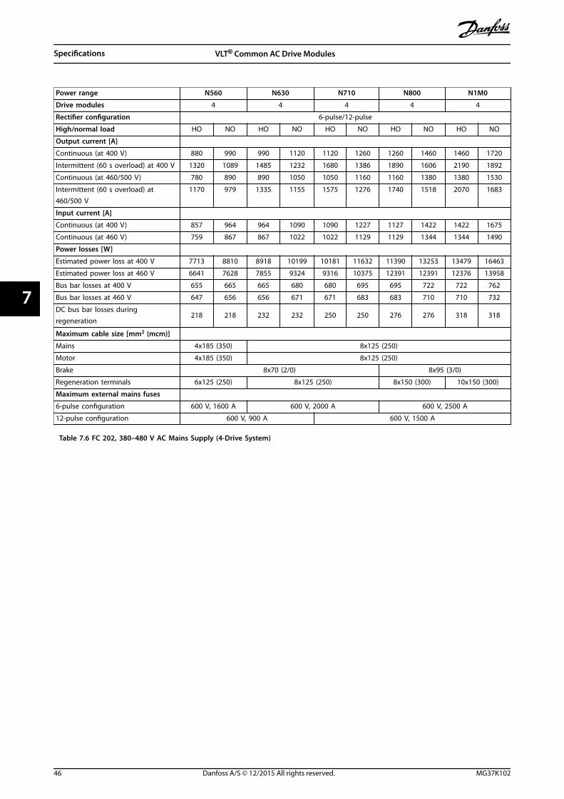
Power range N560 N630 N710 N800 N1M0
Drive modules 4 4 4 4 4
Rectifier configuration 6-pulse/12-pulse
High/normal load HO NO HO NO HO NO HO NO HO NO
Output current [A]
Continuous (at 400 V) 880 990 990 1120 1120 1260 1260 1460 1460 1720
Intermittent (60 s overload) at 400 V 1320 1089 1485 1232 1680 1386 1890 1606 2190 1892
Continuous (at 460/500 V) 780 890 890 1050 1050 1160 1160 1380 1380 1530
Intermittent (60 s overload) at460/500 V
1170 979 1335 1155 1575 1276 1740 1518 2070 1683
Input current [A]
Continuous (at 400 V) 857 964 964 1090 1090 1227 1127 1422 1422 1675
Continuous (at 460 V) 759 867 867 1022 1022 1129 1129 1344 1344 1490
Power losses [W]
Estimated power loss at 400 V 7713 8810 8918 10199 10181 11632 11390 13253 13479 16463
Estimated power loss at 460 V 6641 7628 7855 9324 9316 10375 12391 12391 12376 13958
Bus bar losses at 400 V 655 665 665 680 680 695 695 722 722 762
Bus bar losses at 460 V 647 656 656 671 671 683 683 710 710 732
DC bus bar losses duringregeneration
218 218 232 232 250 250 276 276 318 318
Maximum cable size [mm2 (mcm)]
Mains 4x185 (350) 8x125 (250)
Motor 4x185 (350) 8x125 (250)
Brake 8x70 (2/0) 8x95 (3/0)
Regeneration terminals 6x125 (250) 8x125 (250) 8x150 (300) 10x150 (300)
Maximum external mains fuses
6-pulse configuration 600 V, 1600 A 600 V, 2000 A 600 V, 2500 A
12-pulse configuration 600 V, 900 A 600 V, 1500 A
Table 7.6 FC 202, 380–480 V AC Mains Supply (4-Drive System)
Specifications VLT® Common AC Drive Modules
46 Danfoss A/S © 12/2015 All rights reserved. MG37K102
77

Power range N315 N400 N450
Drive modules 2 2 2
Rectifier configuration 12-pulse
High/normal load HO NO HO NO HO NO
Output current [A]
Continuous (at 550 V) 303 360 360 418 395 470
Intermittent (60 s overload) at 550 V 455 396 560 460 593 517
Continuous (at 575/690 V) 290 344 344 400 380 450
Intermittent (60 s overload) at 575/690 V 435 378 516 440 570 495
Input current [A]
Continuous (at 550 V) 299 355 355 408 381 453
Continuous (at 575 V) 286 339 339 490 366 434
Continuous (at 690 V) 296 352 352 400 366 434
Power losses [W]
Estimated power loss at 575 V 3688 4401 4081 4789 4502 5457
Estimated power loss at 690 V 3669 4352 4020 4709 4447 5354
Bus bar losses at 575 V 538 540 540 541 540 544
DC bus bar losses during regeneration 88 88 89 89 90 90
Maximum cable size [mm2 (mcm)]
Mains 2x120 (250) 4x120 (250)
Motor 2x120 (250) 4x120 (250)
Brake 4x70 (2/0)
Regeneration terminals 4x120 (250)
Maximum external mains fuses 700 V, 550 A
Table 7.7 FC 202, 525–690 V AC Mains Supply (2-Drive System)
Specifications Installation Guide
MG37K102 Danfoss A/S © 12/2015 All rights reserved. 47
7 7

Power range N500 N560 N630
Drive modules 2 2 2
Rectifier configuration 12-pulse
High/normal load HO NO HO NO HO NO
Output current [A]
Continuous (at 550 V) 429 523 523 596 596 630
Intermittent (60 s overload) at 550 V 644 575 785 656 894 693
Continuous (at 575/690 V) 410 500 500 570 570 630
Intermittent (60 s overload) at 575/690 V 615 550 750 627 627 693
Input current [A]
Continuous (at 550 V) 413 504 504 574 574 607
Continuous (at 575 V) 395 482 482 549 549 607
Continuous (at 690 V) 395 482 482 549 549 607
Power losses [W]
Estimated power loss at 575 V 4892 6076 6016 6995 6941 7431
Estimated power loss at 690 V 4797 5951 5886 6831 6766 7638
Bus bar losses at 575 V 542 546 546 550 550 553
DC bus bar losses during regeneration 91 91 186 186 191 191
Maximum cable size [mm2 (mcm)]
Mains 4x120 (250)
Motor 4x120 (250)
Brake 4x70 (2/0) 4x95 (3/0)
Regeneration terminals 4x120 (250)
Maximum external mains fuses 700 V, 630 A
Table 7.8 FC 202, 525–690 V AC Mains Supply (2-Drive System)
Specifications VLT® Common AC Drive Modules
48 Danfoss A/S © 12/2015 All rights reserved. MG37K102
77

Power range N710 N800 N900 N1M0 N1M2
Drive modules 4 4 4 4 4
Rectifier configuration 6-pulse/12-pulse
High/normal load HO NO HO NO HO NO HO NO HO NO
Output current [A]
Continuous (at 550 V) 659 763 763 889 889 988 988 1108 1108 1317
Intermittent (60 s overload) at 550 V 989 839 1145 978 1334 1087 1482 1219 1662 1449
Continuous (at 575/690 V) 630 730 730 850 850 945 945 1060 1060 1260
Intermittent (60 s overload) at575/690 V
945 803 1095 935 1275 1040 1418 1166 1590 1590
Input current [A]
Continuous (at 550 V) 642 743 743 866 866 962 1079 1079 1079 1282
Continuous (at 575 V) 613 711 711 828 828 920 1032 1032 1032 1227
Continuous (at 690 V) 613 711 711 828 828 920 1032 1032 1032 1227
Power losses [W]
Estimated power loss at 575 V 7469 8683 8668 10166 10163 11406 11292 12852 12835 15762
Estimated power loss at 690 V 7381 8559 8555 9996 9987 11188 11077 12580 12551 15358
Bus bar losses at 575 V 637 644 644 653 653 661 661 672 672 695
DC bus bar losses duringregeneration
198 198 208 208 218 218 231 231 256 256
Maximum cable size [mm2 (mcm)]
Mains 4x120 (250) 6x120 (250) 8x120 (250)
Motor 4x120 (250) 6x120 (250) 8x120 (250)
Brake 8x70 (2/0) 8x95 (3/0)
Regeneration terminals 4x150 (300) 6x120 (250) 6x150 (300) 8x120 (250)
Maximum external mains fuses
6-pulse configuration 700 V, 1600 A 700 V, 2000 A
12-pulse configuration 700 V, 900 A 700 V, 1500 A
Table 7.9 FC 202, 525–690 V AC Mains Supply (4-Drive System)
Specifications Installation Guide
MG37K102 Danfoss A/S © 12/2015 All rights reserved. 49
7 7

7.1.3 VLT® AutomationDrive FC 302
Power range N250 N315 N355 N400 N450
Drive modules 2 2 2 2 2
Rectifier configuration 12-pulse 6-pulse/12-pulse
High/normal load HO NO HO NO HO NO HO NO HO NO
Output current [A]
Continuous (at 380–440 V) 480 588 600 658 658 745 695 800 810 880
Intermittent (60 s overload) at 400 V 720 647 900 724 987 820 1043 880 1215 968
Continuous (at 460/500 V) 443 535 540 590 590 678 678 730 730 780
Intermittent (60 s overload) at460/500 V
665 588 810 649 885 746 1017 803 1095 858
Input current [A]
Continuous (at 400 V) 463 567 590 647 647 733 684 787 779 857
Continuous (at 460/500 V) 427 516 531 580 580 667 667 718 711 759
Power losses [W]
Estimated power loss at 400 V 4505 5825 5502 6110 6110 7069 6375 7538 7526 8468
Estimated power loss at 460 V 4063 4998 5384 5964 5721 6175 6070 6609 6604 7140
Bus bar losses at 400 V 545 550 551 555 555 561 557 565 566 575
Bus bar losses at 460 V 543 548 548 551 556 556 556 560 560 563
Maximum cable size [mm2 (mcm)]
Mains 4x120 (250) 4x150 (300)
Motor 4x120 (250) 4x150 (300)
Brake 4x70 (2/0) 4x95 (3/0)
Regeneration terminals 4x120 (250) 4x150 (300) 6x120 (250)
Maximum external mains fuses
6-pulse configuration – – – – 600 V, 1600 A
12-pulse configuration 600 V, 700 A 600 V, 900 A
Table 7.10 FC 302, 380–500 V AC Mains Supply (2-Drive System)
Specifications VLT® Common AC Drive Modules
50 Danfoss A/S © 12/2015 All rights reserved. MG37K102
77

Power range N500 N560 N630 N710 N800
Drive modules 4 4 4 4 4
Rectifier configuration 6-pulse/12-pulse
High/normal load HO NO HO NO HO NO HO NO HO NO
Output current [A]
Continuous (at 380–440 V) 880 990 990 1120 1120 1260 1260 1460 1460 1720
Intermittent (60 s overload) at 400 V 1320 1089 1485 1232 1680 1386 1890 1606 2190 1892
Continuous (at 460/500 V) 780 890 890 1050 1050 1160 1160 1380 1380 1530
Intermittent (60 s overload) at 460/500 V 1170 979 1335 1155 1575 1276 1740 1518 2070 1683
Input current [A]
Continuous (at 400 V) 857 964 964 1090 1090 1227 1227 1422 1422 1675
Continuous (at 460/500 V) 759 867 867 1022 1022 1129 1129 1344 1344 1490
Power losses [W]
Estimated power loss at 400 V 7713 8810 8918 10199 10181 11632 11390 13253 13479 16463
Estimated power loss at 460 V 6641 7628 7855 9324 9316 10375 12391 12391 12376 13958
Bus bar losses at 400 V 655 665 665 680 680 695 695 722 722 762
Bus bar losses at 460 V 647 656 656 671 671 683 683 710 710 732
DC bus bar losses during regeneration 218 218 232 232 250 276 276 276 318 318
Maximum cable size [mm2 (mcm)]
Mains 4x185 (350) 8x120 (250)
Motor 4x185 (350) 8x120 (250)
Brake 8x70 (2/0) 8x95 (3/0)
Regeneration terminals 6x125 (250) 8x125 (250) 8x150 (300) 10x150 (300)
Maximum external mains fuses
6-pulse configuration 600 V, 1600 A 600 V, 2000 A 600 V, 2500 A
12-pulse configuration 600 V, 900 A 600 V, 1500 A
Table 7.11 FC 302, 380–500 V AC Mains Supply (4-Drive System)
Specifications Installation Guide
MG37K102 Danfoss A/S © 12/2015 All rights reserved. 51
7 7

Power range N250 N315 N355 N400
Drive modules 2 2 2 2
Rectifier configuration 12-pulse
High/normal load HO NO HO NO HO NO HO NO
Output current [A]
Continuous (at 550 V) 303 360 360 418 395 470 429 523
Intermittent (60 s overload) at 550 V 455 396 560 360 593 517 644 575
Continuous (at 575/690 V) 290 344 344 400 380 450 410 500
Intermittent (60 s overload) at 575/690 V 435 378 516 440 570 495 615 550
Input current [A]
Continuous (at 550 V) 299 355 355 408 381 453 413 504
Continuous (at 575 V) 286 339 339 490 366 434 395 482
Continuous (at 690 V) 296 352 352 400 366 434 395 482
Power losses [W]
Estimated power loss at 600 V 3688 4401 4081 4789 4502 5457 4892 6076
Estimated power loss at 690 V 3669 4352 4020 4709 4447 5354 4797 5951
Bus bar losses at 575 V 538 540 540 541 540 544 542 546
DC bus bar losses during regeneration 88 88 89 89 90 90 91 91
Maximum cable size [mm2 (mcm)]
Mains 2x120 (250) 4x120 (250)
Motor 2x120 (250) 4x120 (250)
Brake 4x70 (2/0)
Regeneration terminals 4x120 (250)
Maximum external mains fuses 700 V, 550 A
Table 7.12 FC 302, 525–690 V AC Mains Supply (2-Drive System)
Specifications VLT® Common AC Drive Modules
52 Danfoss A/S © 12/2015 All rights reserved. MG37K102
77

Power range N500 N560
Drive modules 2 2
Rectifier configuration 12-pulse
High/normal load HO NO HO NO
Output current [A]
Continuous (at 550 V) 523 596 596 630
Intermittent (60 s overload) at 550 V 785 656 894 693
Continuous (at 575/690 V) 500 570 570 630
Intermittent (60 s overload) at 575/690 V 750 627 627 693
Input current [A]
Continuous (at 550 V) 504 574 574 607
Continuous (at 575 V) 482 549 549 607
Continuous (at 690 V) 482 549 549 607
Power losses [W]
Estimated power loss at 600 V 6016 6995 6941 7431
Estimated power loss at 690 V 5886 6831 6766 7638
Bus bar losses at 575 V 546 550 550 553
DC bus bar losses during regeneration 186 186 191 191
Maximum cable size [mm2 (mcm)]
Mains 4x120 (250)
Motor 4x120 (250)
Brake 4x95 (3/0)
Regeneration terminals 4x120 (250)
Maximum external mains fuses 700 V, 630 A
Table 7.13 FC 302, 525–690 V AC Mains Supply (2-Drive System)
Specifications Installation Guide
MG37K102 Danfoss A/S © 12/2015 All rights reserved. 53
7 7

Power range N630 N710 N800 N900 N1M0
Drive modules 4 4 4 4 4
Rectifier configuration 6-pulse/12-pulse
High/normal load HO NO HO NO HO NO HO NO HO NO
Output current [A]
Continuous (at 550 V) 659 763 763 889 889 988 988 1108 1108 1317
Intermittent (60 s overload) at 550 V 989 839 1145 978 1334 1087 1482 1219 1662 1449
Continuous (at 575/690 V) 630 730 730 850 850 945 945 1060 1060 1260
Intermittent (60 s overload) at575/690 V
945 803 1095 935 1275 1040 1418 1166 1590 1590
Input current [A]
Continuous (at 550 V) 642 743 743 866 866 962 1079 1079 1079 1282
Continuous (at 575 V) 613 711 711 828 828 920 1032 1032 1032 1227
Continuous (at 690 V) 613 711 711 828 828 920 1032 1032 1032 1227
Power losses [W]
Estimated power loss at 600 V 7469 8683 8668 10166 10163 11406 11292 12852 12835 15762
Estimated power loss at 690 V 7381 8559 8555 9996 9987 11188 11077 12580 12551 15358
Bus bar losses at 575 V 637 644 644 653 653 661 661 672 672 695
DC bus bar losses during regeneration 198 198 208 208 218 218 231 231 256 256
Maximum cable size [mm2 (mcm)]
Mains 4x120 (250) 6x120 (250) 8x120 (250)
Motor 4x120 (250) 6x120 (250) 8x120 (250)
Brake 8x70 (2/0) 8x95 (3/0)
Regeneration terminals 4x150 (300) 6x120 (250) 6x150 (300) 8x120 (250)
Maximum external mains fuses
6-pulse configuration 700 V, 1600 A 700 V, 2000 A
12-pulse configuration 700 V, 900 A 700 V, 1500 A
Table 7.14 FC 302, 525–690 V AC Mains Supply (4-Drive System)
Specifications VLT® Common AC Drive Modules
54 Danfoss A/S © 12/2015 All rights reserved. MG37K102
77

7.2 Mains Supply to Drive Module
Mains supplySupply terminals R/91, S/92, T/93Supply voltage 380–480 V ±10%, 525–690 V ±10%
Mains voltage low/mains voltage drop-out:During low mains voltage, the drive module continues until the DC-link voltage drops below the minimum stop level, whichcorresponds typically to 15% below the lowest rated supply voltage. Power-up and full torque cannot be expected at mainsvoltage lower than 10% below the lowest rated supply voltage. The drive module trips for a detected mains drop-out.
Supply frequency 50/60 Hz ±5%Maximum temporary imbalance between mains phases 3.0% of rated supply voltageTrue power factor (λ) ≥0.99 nominal at rated loadDisplacement power factor (cos Φ) (Approximately 1)Switching on input supply L1, L2, L3 Maximum 1 time per 2 minutesEnvironment according to EN 60664-1 Overvoltage category III/pollution degree 2
The unit is suitable for use on a circuit capable of delivering not more than 85000 RMS symmetrical Amperes, 480/600 V
7.3 Motor Output and Motor Data
Motor outputMotor terminals U/96, V/97, W/98Output voltage 0–100% of supply voltageOutput frequency 0–590 HzSwitching on output UnlimitedRamp times 1–3600 s
Torque characteristicsOverload torque (constant torque) Maximum 150% for 60 s1)
Starting torque Maximum 180% up to 0.5 s1)
Overload torque (variable torque) Maximum 110% for s1)
Starting torque (variable torque) Maximum 135% for s
1) Percentage relates to the nominal torque.
EfficiencyEfficiency 98%1)
1) Efficiency measured at nominal current. For energy efficiency class, see chapter 7.5 Ambient Conditions for Drive Modules. Forpart load losses, see www.danfoss.com/vltenergyefficiency.
7.4 12-Pulse Transformer Specifications
Connection Dy11 d0 or Dyn 11d0Phase shift between secondaries 30°Voltage difference between secondaries <0.5%Short-circuit impedance of secondaries >5%Short-circuit impedance difference between secondaries <5% of short-circuit impedanceOther No grounding of the secondaries allowed. Static shield recommended
7.5 Ambient Conditions for Drive Modules
EnvironmentIP rating IP00Acoustic noise 84 dB (running at full load)Vibration test 0.7 gVibration and shock (IEC 60721-33-3) Class 3M3
Specifications Installation Guide
MG37K102 Danfoss A/S © 12/2015 All rights reserved. 55
7 7

Maximum relative humidity 5–95% (IEC 721–3–3; Class 3K3 (non-condensing)) during operationAggressive environment (IEC 60068-2-43) H2S test Class KdAggressive gases (IEC 60721-3-3) Class 3C3Ambient temperature1) Maximum 45 °C (113 °F) (24-hour average maximum 40 °C (104 °F))Minimum ambient temperature during full-scale operation 0 °C (32 °F)Minimum ambient temperature at reduced performance -10 °C (14 °F)Temperature during storage/transport -25 to +65 °C (-13 to 149 °F)Maximum altitude above sea level without derating 1) 1000 m (3281 ft)
EMC standards, Emission EN 61800-3EMC standards, Immunity EN 61800-4-2, EN 61800-4-3, EN 61800-4-4, EN 61800-4-5, and EN 61800-4-6Energy efficiency class2) IE2
1) Refer to the VLT® Common AC Drive Modules Design Guide for derating for high ambient temperature and derating for highaltitude.2) Determined according to EN 50598-2 at:
• Rated load.
• 90% rated frequency.
• Switching frequency factory setting.
• Switching pattern factory setting.
7.6 Cable Specifications
Cable lengths and cross-sections for control cables1)
Maximum motor cable length, shielded 150 m (492 ft)Maximum motor cable length, unshielded 300 m (984 ft)Maximum cross-section to control terminals, flexible or rigid wire without cable end sleeves 1.5 mm2/16 AWGMaximum cross-section to control terminals, flexible wire with cable end sleeves 1 mm2/18 AWGMaximum cross-section to control terminals, flexible wire with cable end sleeves with collar 0.5 mm2/20 AWGMinimum cross-section to control terminals 0.25 mm2/24 AWGMaximum cross-section to 230 V terminals 2.5 mm2/14 AWGMinimum cross-section to 230 V terminals 0.25 mm2/24 AWG
1) For power cables, see electrical data tables in chapter 7.1 Power-dependent Specifications.
7.7 Control Input/Output and Control Data
Digital inputsProgrammable digital inputs 4 (6)1)
Terminal number 18, 19, 271), 291), 32, 33Logic PNP or NPNVoltage level 0–24 V DCVoltage level, logic 0 PNP <5 V DCVoltage level, logic 1 PNP >10 V DCVoltage level, logic 0 NPN2) >19 V DCVoltage level, logic 1 NPN2) <14 V DCMaximum voltage on input 28 V DCPulse frequency range 0–110 kHz(Duty cycle) Minimum pulse width 4.5 msInput resistance, Ri Approximately 4 kΩ
All digital inputs are galvanically isolated from the supply voltage (PELV) and other high-voltage terminals.1) Terminals 27 and 29 can also be programmed as output.2) Except Safe Torque Off input terminal 37.
Specifications VLT® Common AC Drive Modules
56 Danfoss A/S © 12/2015 All rights reserved. MG37K102
77

Safe Torque Off (STO) Terminal 371), 2) (Terminal 37 is fixed PNP logic)Voltage level 0–24 V DCVoltage level, logic 0 PNP <4 V DCVoltage level, logic 1 PNP >20 V DCMaximum voltage on input 28 V DCTypical input current at 24 V 50 mArms
Typical input current at 20 V 60 mArms
Input capacitance 400 nF
All digital inputs are galvanically isolated from the supply voltage (PELV) and other high-voltage terminals.1) See VLT® Frequency Converters – Safe Torque Off Operating Instructions for further information about terminal 37 and SafeTorque Off.2) When using a contactor with a DC coil with STO, always make a return path for the current from the coil when turning it off.The return path can be made by using a freewheel diode across the coil. Alternatively, use a 30 V or 50 V MOV for quickerresponse time. Typical contactors can be bought with this diode.
Analog inputsNumber of analog inputs 2Terminal number 53, 54Modes Voltage or currentMode select Switch S201 and switch S202Voltage mode Switch S201/switch S202 = OFF (U)Voltage level -10 V to +10 V (scalable)Input resistance, Ri Approximately 10 kΩMaximum voltage ±20 VCurrent mode Switch S201/switch S202 = ON (I)Current level 0/4–20 mA (scalable)Input resistance, Ri Approximately 200 ΩMaximum current 30 mAResolution for analog inputs 10 bit (+ sign)Accuracy of analog inputs Maximum error 0.5% of full scaleBandwidth 20 Hz/100 Hz
The analog inputs are galvanically isolated from the supply voltage (PELV) and other high-voltage terminals.
Mains
Functionalisolation
PELV isolation
Motor
DC-Bus
Highvoltage
Control+24V
RS485
18
37
130B
A11
7.10
Illustration 7.1 PELV Isolation
Pulse inputProgrammable pulse 2/1Terminal number pulse 291), 32/33Maximum frequency at terminal 29, 33 110 kHz (Push-pull driven)Maximum frequency at terminal 29, 33 5 kHz (open collector)Minimum frequency at terminal 29, 33 4 HzVoltage level 0–24 V DCMaximum voltage on input 28 V DCInput resistance, Ri Approximately 4 kΩPulse input accuracy (0.1–1 kHz) Maximum error: 0.1% of full scale
Specifications Installation Guide
MG37K102 Danfoss A/S © 12/2015 All rights reserved. 57
7 7

Encoder input accuracy (1–11 kHz) Maximum error: 0.05% of full scale
The pulse and encoder inputs (terminals 29, 32, 33) are galvanically isolated from the supply voltage (PELV) and other high-voltage terminals.1) Pulse inputs are 29 and 33.
Analog outputNumber of programmable analog outputs 1Terminal number 42Current range at analog output 0/4–20 mAMaximum load GND - analog output 500 ΩAccuracy on analog output Maximum error: 0.5% of full scaleResolution on analog output 12 bit
The analog output is galvanically isolated from the supply voltage (PELV) and other high-voltage terminals.
Control card, RS485 serial communicationTerminal number 68 (P, TX+, RX+), 69 (N, TX-, RX-)Terminal number 61 Common for terminals 68 and 69
The RS485 serial communication circuit is functionally separated from other central circuits and galvanically isolated from thesupply voltage (PELV).
Digital outputProgrammable digital/pulse outputs 2Terminal number 27, 291)
Voltage level at digital/frequency output 0–24 VMaximum output current (sink or source) 40 mAMaximum load at frequency output 1 kΩMaximum capacitive load at frequency output 10 nFMinimum output frequency at frequency output 0 HzMaximum output frequency at frequency output 32 kHzAccuracy of frequency output Maximum error: 0.1% of full scaleResolution of frequency outputs 12 bit
1) Terminals 27 and 29 can also be programmed as input.The digital output is galvanically isolated from the supply voltage (PELV) and other high-voltage terminals.
Control card, 24 V DC outputTerminal number 12, 13Output voltage 24 V +1, -3 VMaximum load 200 mA
The 24 V DC supply is galvanically isolated from the supply voltage (PELV), but has the same potential as the analog and digitalinputs and outputs.
Relay outputsProgrammable relay outputs 2Relay 01 terminal number 1–3 (break), 1–2 (make)Maximum terminal load (AC-1)1) on 1–3 (NC), 1–2 (NO) (Resistive load) 240 V AC, 2 AMaximum terminal load (AC-15)1) (Inductive load @ cosφ 0.4) 240 V AC, 0.2 AMaximum terminal load (DC-1)1) on 1–2 (NO), 1–3 (NC) (Resistive load) 60 V DC, 1 AMaximum terminal load (DC-13)1) (Inductive load) 24 V DC, 0.1 ARelay 02 (FC 302 only) Terminal number 4–6 (break), 4–5 (make)Maximum terminal load (AC-1)1) on 4–5 (NO) (Resistive load)2)3) Overvoltage category II 400 V AC, 2 AMaximum terminal load (AC-15)1) on 4–5 (NO) (Inductive load @ cosφ 0.4) 240 V AC, 0.2 AMaximum terminal load (DC-1)1) on 4–5 (NO) (Resistive load) 80 V DC, 2 AMaximum terminal load (DC-13)1) on 4–5 (NO) (Inductive load) 24 V DC, 0.1 AMaximum terminal load (AC-1)1) on 4–6 (NC) (Resistive load) 240 V AC, 2 AMaximum terminal load (AC-15)1) on 4–6 (NC) (Inductive load @ cosφ 0.4) 240 V AC, 0.2 AMaximum terminal load (DC-1)1) on 4–6 (NC) (Resistive load) 50 V DC, 2 A
Specifications VLT® Common AC Drive Modules
58 Danfoss A/S © 12/2015 All rights reserved. MG37K102
77

Maximum terminal load (DC-13)1) on 4–6 (NC) (Inductive load) 24 V DC, 0.1 AMinimum terminal load on 1–3 (NC), 1–2 (NO), 4–6 (NC), 4–5 (NO) 24 V DC 10 mA, 24 V AC 20 mAEnvironment according to EN 60664-1 Overvoltage category III/pollution degree 2
1) IEC 60947 part 4 and 5.The relay contacts are galvanically isolated from the rest of the circuit by reinforced isolation (PELV).2) Overvoltage Category II.3) UL applications 300 V AC2A.
Control card, 10 V DC outputTerminal number 50Output voltage 10.5 V ±0.5 VMaximum load 25 mA
The 10 V DC supply is galvanically isolated from the supply voltage (PELV) and other high-voltage terminals.
Control characteristicsResolution of output frequency at 0–590 Hz ±0.003 HzRepeat accuracy of precise start/stop (terminals 18, 19) ≤±0.1 msSystem response time (terminals 18, 19, 27, 29, 32, 33) ≤10 msSpeed control range (open loop) 1:100 of synchronous speedSpeed control range (closed loop) 1:1000 of synchronous speedSpeed accuracy (open loop) 30–4000 RPM: error ±8 RPMSpeed accuracy (closed loop), depending on resolution of feedback device 0–6000 RPM: error ±0.15 RPM
All control characteristics are based on a 4-pole asynchronous motor
Control card performanceScan interval 5 ms
Control card, USB serial communicationUSB standard 1.1 (full speed)USB plug USB type B device plug
Connection to PC is carried out via a standard host/device USB cable.The USB connection is galvanically isolated from the supply voltage (PELV) and other high-voltage terminals.The USB ground connection is NOT galvanically isolated from protective earth. Use only an isolated laptop as PC connection tothe USB connector on the frequency converter.
Specifications Installation Guide
MG37K102 Danfoss A/S © 12/2015 All rights reserved. 59
7 7

7.8 Kit Dimensions
7.8.1 Drive Module
Illustration 7.2 shows the dimensions of the drive module related to its installation.
346.2[13.6]
868.
3[3
4.2]85
6.6
[33.
7]
1050
.6[4
1.4]
1095
.6[4
3.1]
1121
.7[4
4.2]
130
[5.1
]
40.5
[1.6
]10
48.3
[41.
3]
280[11.0]
106.7[4.2]
213.3[8.4]
320[12.6]
271[10.7]
95[3.7]
130B
E654
.10
Illustration 7.2 Common AC Drive Modules Installation Dimensions
Description Module weight [kg (lb)] Length x width x depth [mm (in)]
Drive module 125 (275) 1121.7 x 346.2 x 375 (44.2 x 13.6 x 14.8)
Table 7.15 Drive Module Weight and Dimensions
Specifications VLT® Common AC Drive Modules
60 Danfoss A/S © 12/2015 All rights reserved. MG37K102
77

7.8.2 Terminal Dimensions
A
AB
B
R
S T U V
W
130B
E748
.10
319 (12.6)
200 (7.9)
0 (0.0)
376 (14.8)
Brake terminals
236.8 (9.0) 293 (11.5)
0 (0
.0)
33 (1
.3)
91 (3
.6)
149
(5.8
)
211
(8.3
)
319
(12.
6)
265
(10.
4)
Illustration 7.3 Drive Module Terminal Dimensions (Front View)
130B
E749
.10
Section A-AMains Terminals
Section B-BMotor and Brake Terminals
Brake terminal
Motor terminal
Mains terminal
284
(11.
2)
0 (0
.0)
0 (0
.0)
306
(12.
1)
255
(10.
0)
Illustration 7.4 Drive Module Terminal Dimensions (Side Views)
Specifications Installation Guide
MG37K102 Danfoss A/S © 12/2015 All rights reserved. 61
7 7

7.8.3 DC Bus Dimensions
130B
E751
.10
105.5 (4.15)
236 (9.3)126
(4.9) 95 (3.7)
Illustration 7.5 DC Bus Dimensions
7.9 Fastener Tightening Torques
For fastening hardware described in this manual, use the torque values in Table 7.16. These torque values are not intendedfor fastening IGBTs. See the instructions included with those replacement parts for the correct torque values.
Shaft Size Driver Size Torx/Hex Torque (Nm) Torque (in-lb)
M4 T20 Torx/7 mm hex 1.0 9
M5 T25 Torx/8 mm hex 2.3 20
M6 T30 Torx/10 mm hex 4.0 35
M8 T40 Torx/13 mm hex 9.6 85
M10 T50 Torx/17 mm hex 19.1 169
M12 (hex bolts only) 18 mm or 19 mm hex 19.1 169
Table 7.16 General Tightening Torques of Fasteners
7.9.1 Tightening Torques for Terminals
For fastening terminals, use the torque values in Table 7.17.
Mains Motor Regen Load sharing Ground Brake
Bolt size M10 M10 M10 M10 M8 M8
Torque [Nm(in-lbs)]
19–40 (168–354) 19–40 (168–354) 19–40 (168–354) 19–40 (168–354)8.5–20.5(75–181)
8.5–20.5 (75–181)
Table 7.17 Tightening of Terminals
Specifications VLT® Common AC Drive Modules
62 Danfoss A/S © 12/2015 All rights reserved. MG37K102
77
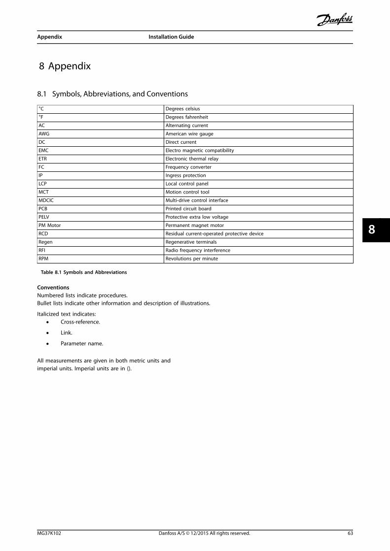
8 Appendix
8.1 Symbols, Abbreviations, and Conventions
°C Degrees celsius
°F Degrees fahrenheit
AC Alternating current
AWG American wire gauge
DC Direct current
EMC Electro magnetic compatibility
ETR Electronic thermal relay
FC Frequency converter
IP Ingress protection
LCP Local control panel
MCT Motion control tool
MDCIC Multi-drive control interface
PCB Printed circuit board
PELV Protective extra low voltage
PM Motor Permanent magnet motor
RCD Residual current-operated protective device
Regen Regenerative terminals
RFI Radio frequency interference
RPM Revolutions per minute
Table 8.1 Symbols and Abbreviations
ConventionsNumbered lists indicate procedures.Bullet lists indicate other information and description of illustrations.
Italicized text indicates:• Cross-reference.
• Link.
• Parameter name.
All measurements are given in both metric units andimperial units. Imperial units are in ().
Appendix Installation Guide
MG37K102 Danfoss A/S © 12/2015 All rights reserved. 63
8 8

8.2 Block Diagrams
8.2.1 Connection of 12-Pulse Disconnector/Interlock
130B
E734
.10
1
2
3
5
6
7
4
8
9
10
1 Drive module 1 6 Disconnector 1
2 Drive module 2 7 Brake fault
3 Supplementary fuses 8 Drive module 3
4 Mains input bus bars 9 Drive module 4
5 Brake fault 10 Disconnector 2
Illustration 8.1 Connection of 12-Pulse Disconnector/Interlock
Appendix VLT® Common AC Drive Modules
64 Danfoss A/S © 12/2015 All rights reserved. MG37K102
88

8.2.2 BRF Connection with 12-Pulse Disconnector/Interlock
1
2
1 2 1 28 7 6 11 10 9
2
11
2
44
43
DC+ DC-MK102
130B
E735
.10
1
2
3
4
1 Auxiliary contact disconnector 1 3 Klixon switch
2 Auxiliary contact disconnector 2 4 BRF connector
Illustration 8.2 BRF Connection with 12-Pulse Disconnector/Interlock
Appendix Installation Guide
MG37K102 Danfoss A/S © 12/2015 All rights reserved. 65
8 8

8.2.3 BRF Jumper Connection
1
2
1 2 1 28 7 6 11 10 9
2
11
2
44
43
DC+ DC-MK102
130B
E736
.10
1
2
1 BRF jumper (pre-installed) 2 BRF connector
Illustration 8.3 BRF Jumper Connection
Appendix VLT® Common AC Drive Modules
66 Danfoss A/S © 12/2015 All rights reserved. MG37K102
88

8.2.4 Connection of Common Brake Resistor
21
130BE737.10
1
2
3
R/91
S/92
T/93
U/96
V/97
W/98
R+
R -
R/91
S/92
T/93
U/96
V/97
W/98
R+
R -
R/91
S/92
T/93
U/96
V/97
W/98
R+
R -
R/91
S/92
T/93
U/96
V/97
W/98
R+
R -
1 Drive module 3 Common brake resistor
2 Brake terminals – –
Illustration 8.4 Connection of Common Brake Resistor
Appendix Installation Guide
MG37K102 Danfoss A/S © 12/2015 All rights reserved. 67
8 8

8.2.5 Klixon Switch Connection
1
2
1 2 1 28 7 6 11 10 9
2
11
2
44
43
DC+ DC-MK102
130B
E738
.10
8
9
1 Klixon switch 2 BRF connector
Illustration 8.5 Klixon Switch Connection
Appendix VLT® Common AC Drive Modules
68 Danfoss A/S © 12/2015 All rights reserved. MG37K102
88

8.2.6 Control Shelf Connections
130B
E739
.10
FC–X
021
1
1
11
12345678910
2
2
34
55
6
6
12
56
12
34
56
2
2
2
4344
4344
43 44
1 2
43 44
1 2
43 44
1 2
43 44
FK100
MK110
MK111MK106
MK1
11
MK1
12M
K114
MK1
13
MK107
MK108
MK109
MK110
FK10
1IN
V1IN
V2IN
V3IN
V4L AC
DCN
230V
129
1011
13
12
53
46
78
1 LCP cradle 8 Terminal block
2 Ribbon cable from LCP to MDCIC 9 Cable to remote-mounted LCP
3 44-pin cable to the drive module 1 (at MK 111) 10 Analog I/O terminals
4 44-pin cable to the drive module 3 (at MK 113) 11 Digital input terminals
5 Current scaling card 12 44-pin cable to the drive module 2 (at MK 112)
6 STO connector 13 44-pin cable to the drive module 4 (at MK 114)
7 STO relay – –
Illustration 8.6 Control Shelf Connections
Appendix Installation Guide
MG37K102 Danfoss A/S © 12/2015 All rights reserved. 69
8 8

8.2.7 Discharge Resistor Connections
130B
E740
.10
R S T U V W R+ R- R S T U V W R+ R- R S T U V W R+ R- R S T U V W R+ R-
BASEDRIVE
BASEDRIVE
BASEDRIVE
BASEDRIVE
3
4
1
2
1 Mains input bus bars 3 Discharge resistor
2 Mains contactor/disconnector auxiliary contacts 4 Discharge contactor
Illustration 8.7 Discharge Resistor Connections
Appendix VLT® Common AC Drive Modules
70 Danfoss A/S © 12/2015 All rights reserved. MG37K102
88

8.2.8 Connection of Individual Brake Resistor to Each Drive Module
130B
E741
.10
21 21 21 21
1
2
3
R/91
S/92
T/93
U/96
V/97
W/98
R+
R -
R/91
S/92
T/93
U/96
V/97
W/98
R+
R -
R/91
S/92
T/93
U/96
V/97
W/98
R+
R -
R/91
S/92
T/93
U/96
V/97
W/98
R+
R -
1 Drive module 3 Individual brake resistors
2 Brake terminals – –
Illustration 8.8 Connection of Individual Brake Resistor to Each Drive Module
Appendix Installation Guide
MG37K102 Danfoss A/S © 12/2015 All rights reserved. 71
8 8

8.2.9 Connections in 6-Pulse 2-Drive Module System
130B
E742
.10
R/91
S/92
T/93
U/96
V/97
W/98
R+
R -
R/91
S/92
T/93
U/96
V/97
W/98
R+
R -
5
6
7
8
1
2
3
4
1 DC fuses 5 DC-link bus bars
2 Drive modules 6 DC terminals
3 Mains input bus bars 7 Brake terminals
4 Mains input terminals 8 Motor output bus bars
Illustration 8.9 Connections in 6-Pulse 2-Drive Module System
Appendix VLT® Common AC Drive Modules
72 Danfoss A/S © 12/2015 All rights reserved. MG37K102
88
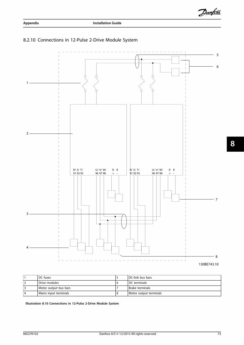
8.2.10 Connections in 12-Pulse 2-Drive Module System
130BE743.10
1
2
3
4
5
6
7
8
R/91
S/92
T/93
U/96
V/97
W/98
R+
R -
R/91
S/92
T/93
U/96
V/97
W/98
R+
R -
1 DC fuses 5 DC-link bus bars
2 Drive modules 6 DC terminals
3 Motor output bus bars 7 Brake terminals
4 Mains input terminals 8 Motor output terminals
Illustration 8.10 Connections in 12-Pulse 2-Drive Module System
Appendix Installation Guide
MG37K102 Danfoss A/S © 12/2015 All rights reserved. 73
8 8

8.2.11 Connections in 4-Drive Module System
130B
E744
.10
R/91
S/92
T/93
U/96
V/97
W/98
R+
R -
R/91
S/92
T/93
U/96
V/97
W/98
R+
R -
R/91
S/92
T/93
U/96
V/97
W/98
R+
R -
R/91
S/92
T/93
U/96
V/97
W/98
R+
R -
1
2
3
4
5
6
7
8
9
1 DC fuses 6 DC terminals
2 Drive module 7 Brake terminals
3 Mains input bus bars 8 Motor output bus bars
4 Mains input terminals 9 Motor output terminals
5 DC-link bus bars – –
Illustration 8.11 Connections in 4-Drive Module System
Appendix VLT® Common AC Drive Modules
74 Danfoss A/S © 12/2015 All rights reserved. MG37K102
88
Index
AA53 switch............................................................................................... 33
A54 switch............................................................................................... 33
Abbreviations......................................................................................... 63
AC mains............................................................................................. 7, 26
AC waveform............................................................................................ 7
Analog input................................................................................... 31, 32
Analog output................................................................................ 31, 32
BBus termination switch....................................................................... 33
CCable
Clamp................................................................................................... 34Control.......................................................................................... 34, 37Equalizing........................................................................................... 37Motor............................................................................................. 25, 34Routing................................................................................................ 38Shielded........................................................................................ 37, 38
Circuit breakers...................................................................................... 38
Closed loop............................................................................................. 33
Conduit..................................................................................................... 38
Control card, USB serial communication..................................... 59
Control system......................................................................................... 7
Control terminal.................................................................................... 33
Control terminal types........................................................................ 31
Control wiring........................................................................................ 38
Conventions........................................................................................... 63
Cooling clearance................................................................................. 38
DDigital input.............................................................................. 31, 32, 33
Discharge time......................................................................................... 5
Disconnect switch................................................................................ 39
Disposal instruction............................................................................... 4
EElectrical installation, EMC guidelines.......................................... 34
Electronic thermal relay..................................................................... 19
EMC............................................................................................................ 37
EMC precautions................................................................................... 34
Energy efficiency................................................................................... 55
Energy efficiency class........................................................................ 55
ETR............................................................................................................. 19
External controllers................................................................................ 7
FFans............................................................................................................ 14
Feedback........................................................................................... 33, 38
Fuses................................................................................................... 19, 38
GGround connections............................................................................ 38
Ground loop........................................................................................... 37
Grounding.......................................................................... 26, 27, 38, 39
Grounding, shielded control cable................................................. 37
HHigh voltage.................................................................................. 5, 6, 39
IInput current.......................................................................................... 26
Input power..................................................................................... 38, 39
Input signal............................................................................................. 33
Input terminal................................................................................. 33, 39
Input voltage.......................................................................................... 39
Installation.............................................................................................. 38
Interference isolation.......................................................................... 38
Items supplied....................................................................................... 11
JJumper...................................................................................................... 33
LLeakage current (>3.5 mA).................................................................. 6
Lifting the unit....................................................................................... 12
MMains terminal....................................................................................... 33
MotorCable....................................................................................... 19, 25, 34Output.................................................................................................. 55Used with frequency converter..................................................... 7Wiring................................................................................................... 38
Mounting................................................................................................. 38
Multiple frequency converters........................................................ 19
NNameplate............................................................................................... 11
OOpen loop............................................................................................... 33
Optional equipment..................................................................... 33, 39
Index Installation Guide
MG37K102 Danfoss A/S © 12/2015 All rights reserved. 75
Output relay........................................................................................... 58
Output terminal.................................................................................... 39
Overcurrent protection...................................................................... 19
PPower connection................................................................................ 19
Power factor........................................................................................... 38
Precautions EMC................................................................................... 34
Programming......................................................................................... 33
QQualified personnel................................................................................ 5
RRecycling.................................................................................................... 4
Relay.......................................................................................................... 32
Relay output............................................................................. 31, 34, 58
Remote commands................................................................................ 7
RS485........................................................................................................ 33
SSafe Torque Off...................................................................................... 34
Safety.................................................................................................... 6, 39
Serial communication...................................................... 7, 31, 32, 37
Shielded twisted pair (STP)............................................................... 33
Speed reference.................................................................................... 33
STO............................................................................................................. 34
Supply voltage......................................................................... 31, 32, 39
Switch....................................................................................................... 33
Symbols.................................................................................................... 63
System feedback..................................................................................... 7
TTerminal 53............................................................................................. 33
Terminal 54............................................................................................. 33
Terminals, tightening.......................................................................... 62
Thermistor............................................................................................... 31
Thermistor control wiring.................................................................. 31
Tightening, general.............................................................................. 62
Tightening, terminals.......................................................................... 62
Transformers used with 12-Pulse.................................................... 55
UUnintended start.............................................................................. 5, 39
VVoltage level........................................................................................... 56
WWarranty.................................................................................................. 11
Wire sizes.......................................................................................... 19, 25
WiringControl................................................................................................. 38Control terminal............................................................................... 33Motor.................................................................................................... 38
Index VLT® Common AC Drive Modules
76 Danfoss A/S © 12/2015 All rights reserved. MG37K102

Index Installation Guide
MG37K102 Danfoss A/S © 12/2015 All rights reserved. 77

Danfoss can accept no responsibility for possible errors in catalogues, brochures and other printed material. Danfoss reserves the right to alter its products without notice. This also applies toproducts already on order provided that such alterations can be made without subsequential changes being necessary in specifications already agreed. All trademarks in this material are propertyof the respective companies. Danfoss and the Danfoss logotype are trademarks of Danfoss A/S. All rights reserved.
Danfoss A/SUlsnaes 1DK-6300 Graastenvlt-drives.danfoss.com
*MG37K102*130R0657 MG37K102 12/2015