VLT® AQUA Drive technical data - brownbros.com.au · Modbus RTU Optional: VLT® PROFIBUS DP V1 MCA...
34
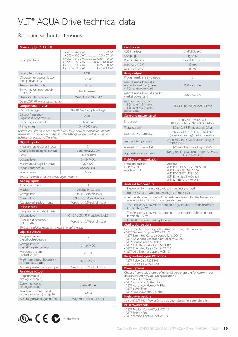
VLT® AQUA Drive technical data VLT® AQUA Drive technical data Basic unit without extensions Global Marine Main supply (L1, L2, L3) Supply voltage 1 x 200 – 240 V AC....................... 1.1 – 22 kW 1 x 380 – 480 V AC....................... 7.5 – 37 kW 3 x 200 – 240 V AC.................... 0.25 – 45 kW 3 x 380 – 480 V AC............... 0.37 – 1000 kW 3 x 525 – 600 V AC.................... 0.75 – 90 kW 3 x 525 – 690 V AC................ 11 – 1400 kW* Supply frequency 50/60 Hz Displacement power factor (cos ф) near unity > 0.98 True power factor (λ) ≥ 0.9 Switching on input supply L1, L2, L3 1–2 times/min. Harmonic disturbance Meets EN 61000-3-12 * Up to 2000 kW available on request Output data (U, V, W) Output voltage 0 – 100% of supply voltage Output frequency (dependent on power size) 0-590 Hz Switching on output Unlimited Ramp times 0.1 – 3600 sec. Note: VLT® AQUA Drive can provide 110%, 150% or 160% current for 1 minute, dependent on power size and parameter settings. Higher overload rating is achieved by oversizing the drive. Digital inputs Programmable digital inputs 6* Changeable to digital output 2 (terminal 27, 29) Logic PNP or NPN Voltage level 0 – 24 V DC Maximum voltage on input 28 V DC Input resistance, Ri Approx. 4 kΩ Scan interval 5 ms * Two of the inputs can be used as digital outputs. Analog inputs Analogue inputs 2 Modes Voltage or current Voltage level 0 to +10 V (scaleable) Current level 0/4 to 20 mA (scaleable) Accuracy of analog inputs Max. error: 0.5% of full scale Pulse inputs Programmable pulse inputs 2* Voltage level 0 – 24 V DC (PNP positive logic) Pulse input accuracy (0.1 – 1 kHz) Max. error: 0.1% of full scale * Two of the digital inputs can be used for pulse inputs. Digital outputs Programmable digital/pulse outputs 2 Voltage level at digital/frequency output 0 – 24 V DC Max. output current (sink or source) 40 mA Maximum output frequency at frequency output 0 to 32 kHz Accuracy on frequency output Max. error: 0.1% of full scale Analogue output Programmable analogue outputs 1 Current range at analogue output 0/4 – 20 mA Max. load to common at analogue output (clamp 30) 500 Ω Accuracy on analogue output Max. error: 1% of full scale Control card USB interface 1.1 (Full Speed) USB plug Type “B” RS485 interface Up to 115 kBaud Max. load (10 V) 15 mA Max. load (24 V) 200 mA Relay output Programmable relay outputs 2 Max. terminal load (AC) on 1-3 (break), 1-2 (make), 4-6 (break) power card 240 V AC, 2 A Max. terminal load (AC) on 4-5 (make) power card 400 V AC, 2 A Min. terminal load on 1-3 (break), 1-2 (make), 4-6 (break), 4-5 (make) power card 24 V DC 10 mA, 24 V AC 20 mA Surroundings/external Enclosure IP: 00/20/21/54/55/66 UL Type: Chassis/1/12/4x Outdoor Vibration test 1.0 g (D, E & F-enclosures: 0.7 g) Max. relative humidity 5% – 95% (IEC 721-3-3; Class 3K3 (non-condensing) during operation Ambient temperature Up to 55°C (50°C without derating; D- frame 45°C) Galvanic isolation of all I/O supplies according to PELV Aggressive environment Designed for coated/uncoated 3C3/3C2 (IEC 60721-3-3) Fieldbus communication Standard built-in: FC Protocol Modbus RTU Optional: VLT® PROFIBUS DP V1 MCA 101 VLT® DeviceNet MCA 104 VLT® PROFINET MCA 120 VLT® EtherNet/IPMCA 121 VLT® Modbus TCP MCA 122 Ambient temperature – Electronic thermal motor protection against overload – Up to 55°C (50°C without derating; D-frame 45°C) – Temperature monitoring of the heatsink ensures that the frequency converter trips in case of overtemperature – The frequency converter is protected against short-circuits on motor terminals U, V, W – The frequency converter is protected against earth faults on motor terminals U, V, W – Protection against mains phase loss Application options Extend the functionality of the drive with integrated options: • VLT® General Purpose I/O MCB 101 • VLT® Extended Cascade Controller MCO 101 • VLT® Advanced Cascade Controller MCO 102 • VLT® Sensor Input MCB 114 • VLT® PTC Thermistor Card MCB 112 • VLT® Extended Relay Card MCB 113 • VLT® 24 V External Supply MCB 107 Relay and analogue I/O option • VLT® Relay Card MCB 105 • VLT® Analog I/O MCB109) Power options Choose from a wide range of external power options for use with our drive in critical networks or applications: • VLT® Low Harmonic Drive • VLT® Advanced Active Filter • VLT® Advanced Harmonic Filter • VLT® dU/dt filter • VLT® Sine wave filter (LC filter) High power options See the VLT® High Power Drive Selection Guide for a complete list. PC software tools • VLT® Motion Control Tool MCT 10 • VLT® Energy Box • VLT® Motion Control Tool MCT 31 39 Danfoss Drives · DKDD.PB.202.A3.02 · VLT® AQUA Drive · 0.25 kW – 2 MW
Transcript of VLT® AQUA Drive technical data - brownbros.com.au · Modbus RTU Optional: VLT® PROFIBUS DP V1 MCA...
VLT® AQUA Drive technical data
VLT® AQUA Drive technical data
Basic unit without extensions
Global Marine
Main supply (L1, L2, L3)
Supply voltage
1 x 200 – 240 V AC ....................... 1.1 – 22 kW1 x 380 – 480 V AC ....................... 7.5 – 37 kW3 x 200 – 240 V AC .................... 0.25 – 45 kW3 x 380 – 480 V AC ...............0.37 – 1000 kW3 x 525 – 600 V AC .................... 0.75 – 90 kW3 x 525 – 690 V AC ................ 11 – 1400 kW*
Supply frequency 50/60 Hz
Displacement power factor(cos ф) near unity
> 0.98
True power factor (λ) ≥ 0.9
Switching on input supply L1, L2, L3
1–2 times/min.
Harmonic disturbance Meets EN 61000-3-12
* Up to 2000 kW available on request
Output data (U, V, W)
Output voltage 0 – 100% of supply voltage
Output frequency (dependent on power size)
0-590 Hz
Switching on output Unlimited
Ramp times 0.1 – 3600 sec.
Note: VLT® AQUA Drive can provide 110%, 150% or 160% current for 1 minute, dependent on power size and parameter settings. Higher overload rating is achieved by oversizing the drive.
Digital inputs
Programmable digital inputs 6*
Changeable to digital output 2 (terminal 27, 29)
Logic PNP or NPN
Voltage level 0 – 24 V DC
Maximum voltage on input 28 V DC
Input resistance, Ri Approx. 4 kΩ
Scan interval 5 ms
* Two of the inputs can be used as digital outputs.
Analog inputs
Analogue inputs 2
Modes Voltage or current
Voltage level 0 to +10 V (scaleable)
Current level 0/4 to 20 mA (scaleable)
Accuracy of analog inputs Max. error: 0.5% of full scale
Pulse inputs
Programmable pulse inputs 2*
Voltage level 0 – 24 V DC (PNP positive logic)
Pulse input accuracy (0.1 – 1 kHz)
Max. error: 0.1% of full scale
* Two of the digital inputs can be used for pulse inputs.
Digital outputs
Programmable digital/pulse outputs
2
Voltage level at digital/frequency output
0 – 24 V DC
Max. output current (sink or source)
40 mA
Maximum output frequency at frequency output
0 to 32 kHz
Accuracy on frequency output Max. error: 0.1% of full scale
Analogue output
Programmable analogue outputs
1
Current range at analogue output
0/4 – 20 mA
Max. load to common at analogue output (clamp 30)
500 Ω
Accuracy on analogue output Max. error: 1% of full scale
Control card
USB interface 1.1 (Full Speed)
USB plug Type “B”
RS485 interface Up to 115 kBaud
Max. load (10 V) 15 mA
Max. load (24 V) 200 mA
Relay output
Programmable relay outputs 2
Max. terminal load (AC) on 1-3 (break), 1-2 (make), 4-6 (break) power card
240 V AC, 2 A
Max. terminal load (AC) on 4-5 (make) power card
400 V AC, 2 A
Min. terminal load on 1-3 (break), 1-2 (make), 4-6 (break), 4-5 (make) power card
24 V DC 10 mA, 24 V AC 20 mA
Surroundings/external
Enclosure IP: 00/20/21/54/55/66
UL Type: Chassis/1/12/4x Outdoor
Vibration test 1.0 g (D, E & F-enclosures: 0.7 g)
Max. relative humidity5% – 95% (IEC 721-3-3; Class 3K3
(non-condensing) during operation
Ambient temperatureUp to 55°C (50°C without derating; D-
frame 45°C)
Galvanic isolation of all I/O supplies according to PELV
Aggressive environmentDesigned for coated/uncoated 3C3/3C2
(IEC 60721-3-3)
Fieldbus communication
Standard built-in:FC Protocol Modbus RTU
Optional:VLT® PROFIBUS DP V1 MCA 101VLT® DeviceNet MCA 104VLT® PROFINET MCA 120VLT® EtherNet/IPMCA 121 VLT® Modbus TCP MCA 122
Ambient temperature
– Electronic thermal motor protection against overload
– Up to 55°C (50°C without derating; D-frame 45°C)
– Temperature monitoring of the heatsink ensures that the frequency converter trips in case of overtemperature
– The frequency converter is protected against short-circuits on motor terminals U, V, W
– The frequency converter is protected against earth faults on motor terminals U, V, W
– Protection against mains phase loss
Application options
Extend the functionality of the drive with integrated options:• VLT® General Purpose I/O MCB 101• VLT® Extended Cascade Controller MCO 101• VLT® Advanced Cascade Controller MCO 102 • VLT® Sensor Input MCB 114 • VLT® PTC Thermistor Card MCB 112• VLT® Extended Relay Card MCB 113• VLT® 24 V External Supply MCB 107
Relay and analogue I/O option
• VLT® Relay Card MCB 105• VLT® Analog I/O MCB109)
Power options
Choose from a wide range of external power options for use with our drive in critical networks or applications:• VLT® Low Harmonic Drive• VLT® Advanced Active Filter• VLT® Advanced Harmonic Filter• VLT® dU/dt fi lter• VLT® Sine wave fi lter (LC fi lter)
High power options
See the VLT® High Power Drive Selection Guide for a complete list.
PC software tools
• VLT® Motion Control Tool MCT 10• VLT® Energy Box• VLT® Motion Control Tool MCT 31
39Danfoss Drives · DKDD.PB.202.A3.02 · VLT® AQUA Drive · 0.25 kW – 2 MW
Enclosure
IP20/Chassis A3
IP21/Type 1B1 B2 C1 C2
IP55/Type 12 + IP66/NEMA 4X A5
P1K1 P1K5 P2K2 P3K0 P3K7 P5K5 P7K5 P15K P22K
Typical shaft output [kW] 1.1 1.5 2.2 3 3.7 5.5 7.5 15 22
Typical shaft output at 240 V [HP] 1.5 2.0 2.9 4.0 4.9 7.5 10 20 30
Output current
Continuous (3x200-240 V) [A] 6.6 7.5 10.6 12.5 16.7 24.2 30.8 59.4 88
Intermittent (3x200-240 V) [A] 7.3 8.3 11.7 13.8 18.4 26.6 33.4 65.3 96.8
Output power
Continuous (208 V AC) [kVA] 2.4 2.7 3.8 4.5 6.0 8.7 11.1 21.4 31.7
Maximum input current
Continuous (1 x 200-240 V) [A] 12.5 15 20.5 24 32 46 59 111 172
Intermittent (1 x 200-240 V) [A] 13.8 16.5 22.6 26.4 35.2 50.6 64.9 122.1 189.2
Max. pre-fuses [A] 20 30 40 60 80 100 150 200
Additional specifi cations
Estimated power loss at rated max. load 3) [W] 44 30 44 60 74 110 150 300 440
Effi ciency 4) 0.98
Max. cable cross-sectionMains, motor, brake
[mm2]([AWG])
0.2-4(4-10)
10(7)
35(2)
50(1/0)
95(4/0)
Max. cable cross-sectionMains with disconnect switch
[mm2]([AWG])
5.26 (10)
16 (6)
25 (3)
50 (1/0)
2 x 50 (2 x 1/0)
9) 10)
Max. cable cross-sectionMains without disconnect switch
[mm2]([AWG])
5.26 (10)16 (6)
25 (3)
50 (1/0)
95 (4/0)
Cable insulation temperature ratings [°C] 75
Weight
IP20/Chassis [kg] (lbs) 4.9 (10.8)
IP21/Type 1 [kg] (lbs) 23 (50.7) 27 (59.5) 45 (99.2) 65 (143.3)
IP55/Type 12, IP66/NEMA 4X [kg] (lbs) 23 (50.7) 27 (59.5) 45 (99.2) 65 (143.3)
Mains supply 1 x 200-240 V AC – normal overload = 110 % torque during 60 s, P1K1-P22K. Mains supply 1 x 200-240 V AC – normal overload = 110 % torque during 60 s, P1K1-P22K. 9) Two wires are required. 10) Variant not available in IP21.
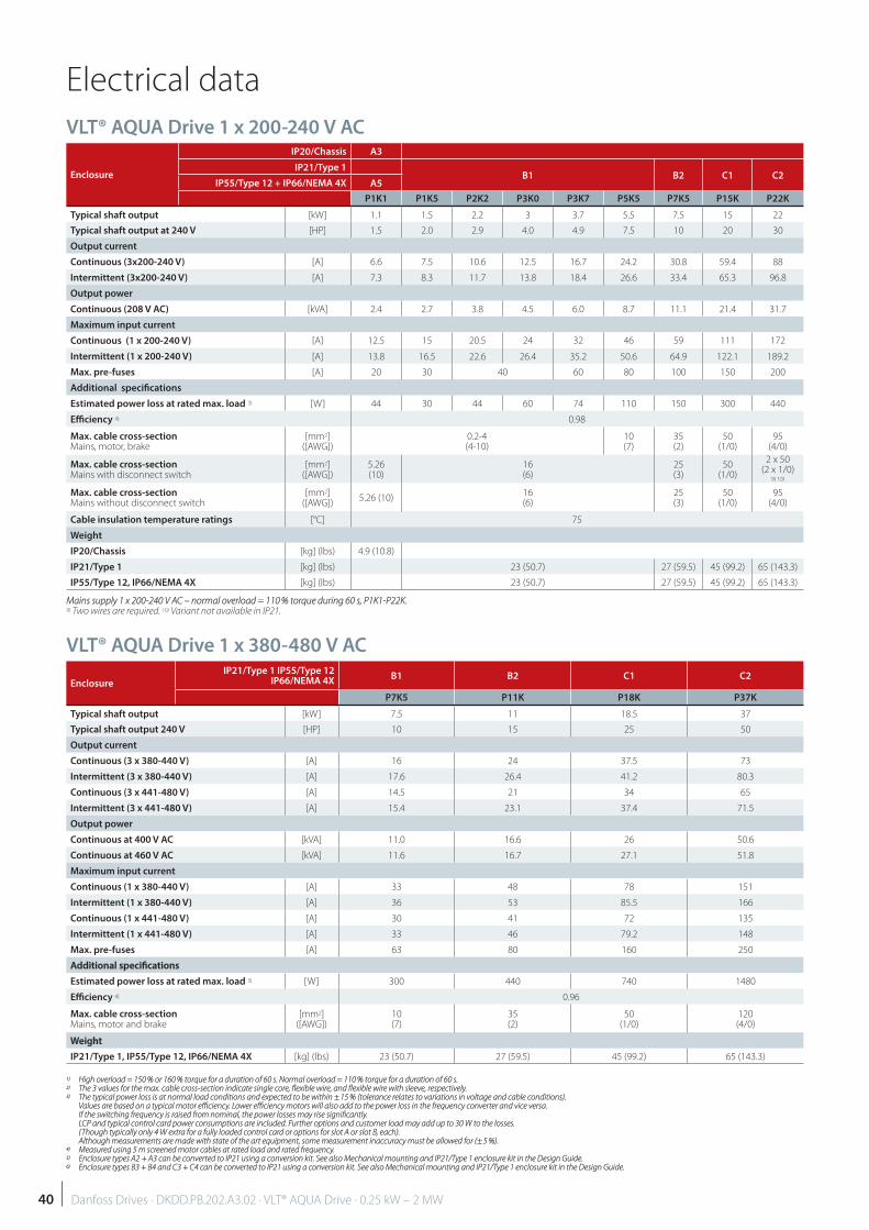
VLT® AQUA Drive 1 x 200-240 V AC
1)1) High overload = 150 % or 160 % torque for a duration of 60 s. Normal overload = 110 % torque for a duration of 60 s. High overload = 150 % or 160 % torque for a duration of 60 s. Normal overload = 110 % torque for a duration of 60 s.2)2) The 3 values for the max. cable cross-section indicate single core, fl exible wire, and fl exible wire with sleeve, respectively. The 3 values for the max. cable cross-section indicate single core, fl exible wire, and fl exible wire with sleeve, respectively.3)3) The typical power loss is at normal load conditions and expected to be within ± 15 % (tolerance relates to variations in voltage and cable conditions). The typical power loss is at normal load conditions and expected to be within ± 15 % (tolerance relates to variations in voltage and cable conditions).
Values are based on a typical motor effi ciency. Lower effi ciency motors will also add to the power loss in the frequency converter and vice versa.Values are based on a typical motor effi ciency. Lower effi ciency motors will also add to the power loss in the frequency converter and vice versa.If the switching frequency is raised from nominal, the power losses may rise signifi cantly. If the switching frequency is raised from nominal, the power losses may rise signifi cantly. LCP and typical control card power consumptions are included. Further options and customer load may add up to 30 W to the losses. LCP and typical control card power consumptions are included. Further options and customer load may add up to 30 W to the losses. (Though typically only 4 W extra for a fully loaded control card or options for slot A or slot B, each).(Though typically only 4 W extra for a fully loaded control card or options for slot A or slot B, each).Although measurements are made with state of the art equipment, some measurement inaccuracy must be allowed for (± 5 %).Although measurements are made with state of the art equipment, some measurement inaccuracy must be allowed for (± 5 %).
4)4) Measured using 5 m screened motor cables at rated load and rated frequency. Measured using 5 m screened motor cables at rated load and rated frequency.5)5) Enclosure types A2 + A3 can be converted to IP21 using a conversion kit. See also Mechanical mounting and IP21/Type 1 enclosure kit in the Design Guide. Enclosure types A2 + A3 can be converted to IP21 using a conversion kit. See also Mechanical mounting and IP21/Type 1 enclosure kit in the Design Guide.6)6) Enclosure types B3 + B4 and C3 + C4 can be converted to IP21 using a conversion kit. See also Mechanical mounting and IP21/Type 1 enclosure kit in the Design Guide. Enclosure types B3 + B4 and C3 + C4 can be converted to IP21 using a conversion kit. See also Mechanical mounting and IP21/Type 1 enclosure kit in the Design Guide.
VLT® AQUA Drive 1 x 380-480 V AC
Enclosure
IP21/Type 1 IP55/Type 12IP66/NEMA 4X
B1 B2 C1 C2
P7K5 P11K P18K P37K
Typical shaft output [kW] 7.5 11 18.5 37
Typical shaft output 240 V [HP] 10 15 25 50
Output current
Continuous (3 x 380-440 V) [A] 16 24 37.5 73
Intermittent (3 x 380-440 V) [A] 17.6 26.4 41.2 80.3
Continuous (3 x 441-480 V) [A] 14.5 21 34 65
Intermittent (3 x 441-480 V) [A] 15.4 23.1 37.4 71.5
Output power
Continuous at 400 V AC [kVA] 11.0 16.6 26 50.6
Continuous at 460 V AC [kVA] 11.6 16.7 27.1 51.8
Maximum input current
Continuous (1 x 380-440 V) [A] 33 48 78 151
Intermittent (1 x 380-440 V) [A] 36 53 85.5 166
Continuous (1 x 441-480 V) [A] 30 41 72 135
Intermittent (1 x 441-480 V) [A] 33 46 79.2 148
Max. pre-fuses [A] 63 80 160 250
Additional specifi cationsAdditional specifi cations
Estimated power loss at rated max. load 3) [W] 300 440 740 1480
Effi ciency 4) 0.96
Max. cable cross-section Mains, motor and brake
[mm2]([AWG])
10(7)
35(2)
50(1/0)
120(4/0)
WeightWeight
IP21/Type 1, IP55/Type 12, IP66/NEMA 4X [kg] (lbs) 23 (50.7) 27 (59.5) 45 (99.2) 65 (143.3)
Electrical data
40 Danfoss Drives · DKDD.PB.202.A3.02 · VLT® AQUA Drive · 0.25 kW – 2 MW
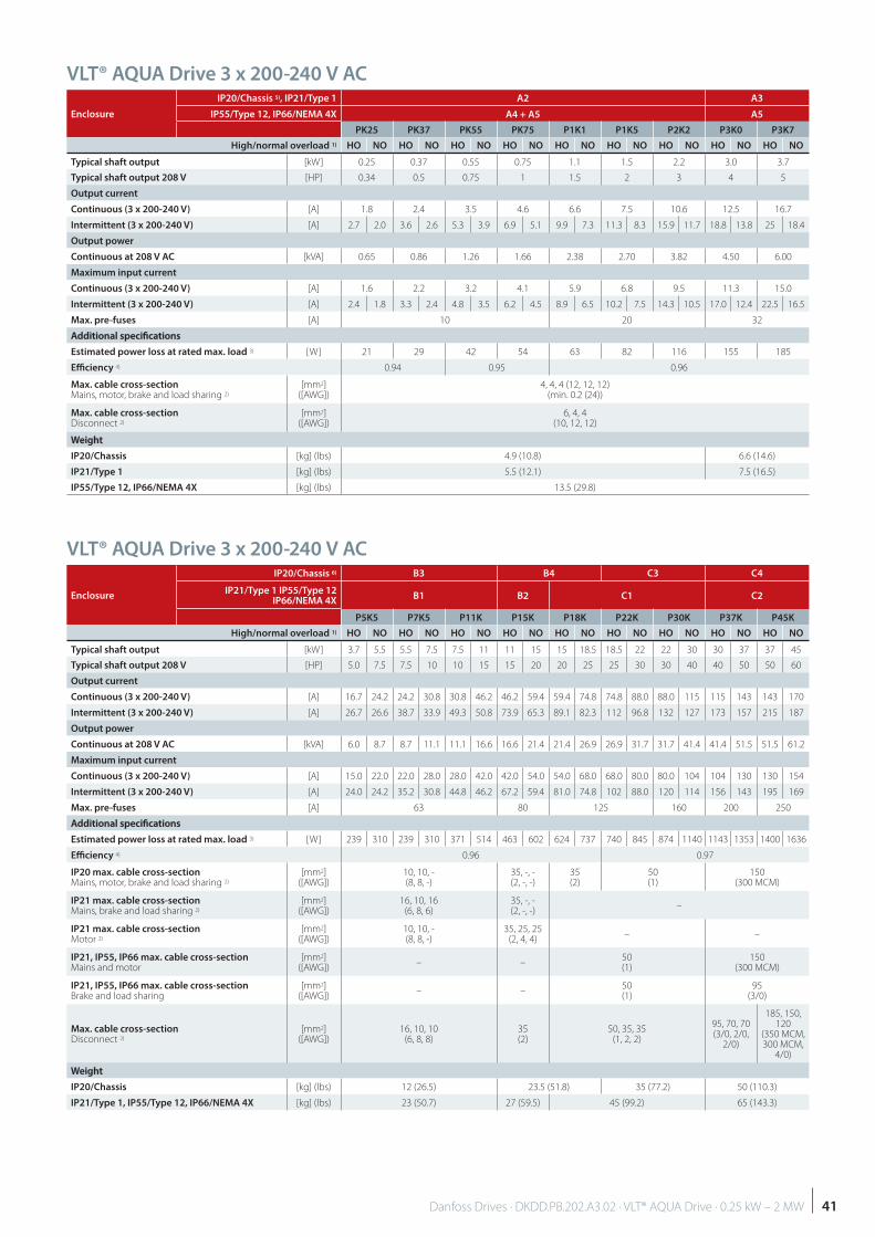
VLT® AQUA Drive 3 x 200-240 V AC
VLT® AQUA Drive 3 x 200-240 V AC
Enclosure
IP20/Chassis 5), IP21/Type 1 A2 A3
IP55/Type 12, IP66/NEMA 4X A4 + A5 A5
PK25 PK37 PK55 PK75 P1K1 P1K5 P2K2 P3K0 P3K7
High/normal overload 1) HO NO HO NO HO NO HO NO HO NO HO NO HO NO HO NO HO NO
Typical shaft output [kW] 0.25 0.37 0.55 0.75 1.1 1.5 2.2 3.0 3.7
Typical shaft output 208 V [HP] 0.34 0.5 0.75 1 1.5 2 3 4 5
Output current
Continuous (3 x 200-240 V) [A] 1.8 2.4 3.5 4.6 6.6 7.5 10.6 12.5 16.7
Intermittent (3 x 200-240 V) [A] 2.7 2.0 3.6 2.6 5.3 3.9 6.9 5.1 9.9 7.3 11.3 8.3 15.9 11.7 18.8 13.8 25 18.4
Output power
Continuous at 208 V AC [kVA] 0.65 0.86 1.26 1.66 2.38 2.70 3.82 4.50 6.00
Maximum input current
Continuous (3 x 200-240 V) [A] 1.6 2.2 3.2 4.1 5.9 6.8 9.5 11.3 15.0
Intermittent (3 x 200-240 V) [A] 2.4 1.8 3.3 2.4 4.8 3.5 6.2 4.5 8.9 6.5 10.2 7.5 14.3 10.5 17.0 12.4 22.5 16.5
Max. pre-fuses [A] 10 20 32
Additional specifi cationsAdditional specifi cations
Estimated power loss at rated max. load 3) [W] 21 29 42 54 63 82 116 155 185
Effi ciency 4) 0.94 0.95 0.96
Max. cable cross-section Mains, motor, brake and load sharing 2)
[mm2]([AWG])
4, 4, 4 (12, 12, 12)(min. 0.2 (24))
Max. cable cross-section Disconnect 2)
[mm2]([AWG])
6, 4, 4 (10, 12, 12)
WeightWeight
IP20/Chassis [kg] (lbs) 4.9 (10.8) 6.6 (14.6)
IP21/Type 1 [kg] (lbs) 5.5 (12.1) 7.5 (16.5)
IP55/Type 12, IP66/NEMA 4X [kg] (lbs) 13.5 (29.8)
Enclosure
IP20/Chassis 6) B3 B4 C3 C4
IP21/Type 1 IP55/Type 12IP66/NEMA 4X
B1 B2 C1 C2
P5K5 P7K5 P11K P15K P18K P22K P30K P37K P45K
High/normal overload 1) HO NO HO NO HO NO HO NO HO NO HO NO HO NO HO NO HO NO
Typical shaft output [kW] 3.7 5.5 5.5 7.5 7.5 11 11 15 15 18.5 18.5 22 22 30 30 37 37 45
Typical shaft output 208 V [HP] 5.0 7.5 7.5 10 10 15 15 20 20 25 25 30 30 40 40 50 50 60
Output current
Continuous (3 x 200-240 V) [A] 16.7 24.2 24.2 30.8 30.8 46.2 46.2 59.4 59.4 74.8 74.8 88.0 88.0 115 115 143 143 170
Intermittent (3 x 200-240 V) [A] 26.7 26.6 38.7 33.9 49.3 50.8 73.9 65.3 89.1 82.3 112 96.8 132 127 173 157 215 187
Output power
Continuous at 208 V AC [kVA] 6.0 8.7 8.7 11.1 11.1 16.6 16.6 21.4 21.4 26.9 26.9 31.7 31.7 41.4 41.4 51.5 51.5 61.2
Maximum input current
Continuous (3 x 200-240 V) [A] 15.0 22.0 22.0 28.0 28.0 42.0 42.0 54.0 54.0 68.0 68.0 80.0 80.0 104 104 130 130 154
Intermittent (3 x 200-240 V) [A] 24.0 24.2 35.2 30.8 44.8 46.2 67.2 59.4 81.0 74.8 102 88.0 120 114 156 143 195 169
Max. pre-fuses [A] 63 80 125 160 200 250
Additional specifi cationsAdditional specifi cations
Estimated power loss at rated max. load 3) [W] 239 310 239 310 371 514 463 602 624 737 740 845 874 1140 1143 1353 1400 1636
Effi ciency 4) 0.96 0.97
IP20 max. cable cross-section Mains, motor, brake and load sharing 2)
[mm2]([AWG])
10, 10, -(8, 8, -)
35, -, -(2, -, -)
35(2)
50(1)
150(300 MCM)
IP21 max. cable cross-section Mains, brake and load sharing 2)
[mm2]([AWG])
16, 10, 16(6, 8, 6)
35, -, -(2, -, -)
–
IP21 max. cable cross-section Motor 2)
[mm2]([AWG])
10, 10, -(8, 8, -)
35, 25, 25(2, 4, 4)
– –
IP21, IP55, IP66 max. cable cross-section Mains and motor
[mm2]([AWG])
– –50(1)
150(300 MCM)
IP21, IP55, IP66 max. cable cross-section Brake and load sharing
[mm2]([AWG])
– –50(1)
95(3/0)
Max. cable cross-section Disconnect 2)
[mm2]([AWG])
16, 10, 10(6, 8, 8)
35(2)
50, 35, 35(1, 2, 2)
95, 70, 70(3/0, 2/0,
2/0)
185, 150, 120
(350 MCM, 300 MCM,
4/0)
WeightWeight
IP20/Chassis [kg] (lbs) 12 (26.5) 23.5 (51.8) 35 (77.2) 50 (110.3)
IP21/Type 1, IP55/Type 12, IP66/NEMA 4X [kg] (lbs) 23 (50.7) 27 (59.5) 45 (99.2) 65 (143.3)
41Danfoss Drives · DKDD.PB.202.A3.02 · VLT® AQUA Drive · 0.25 kW – 2 MW
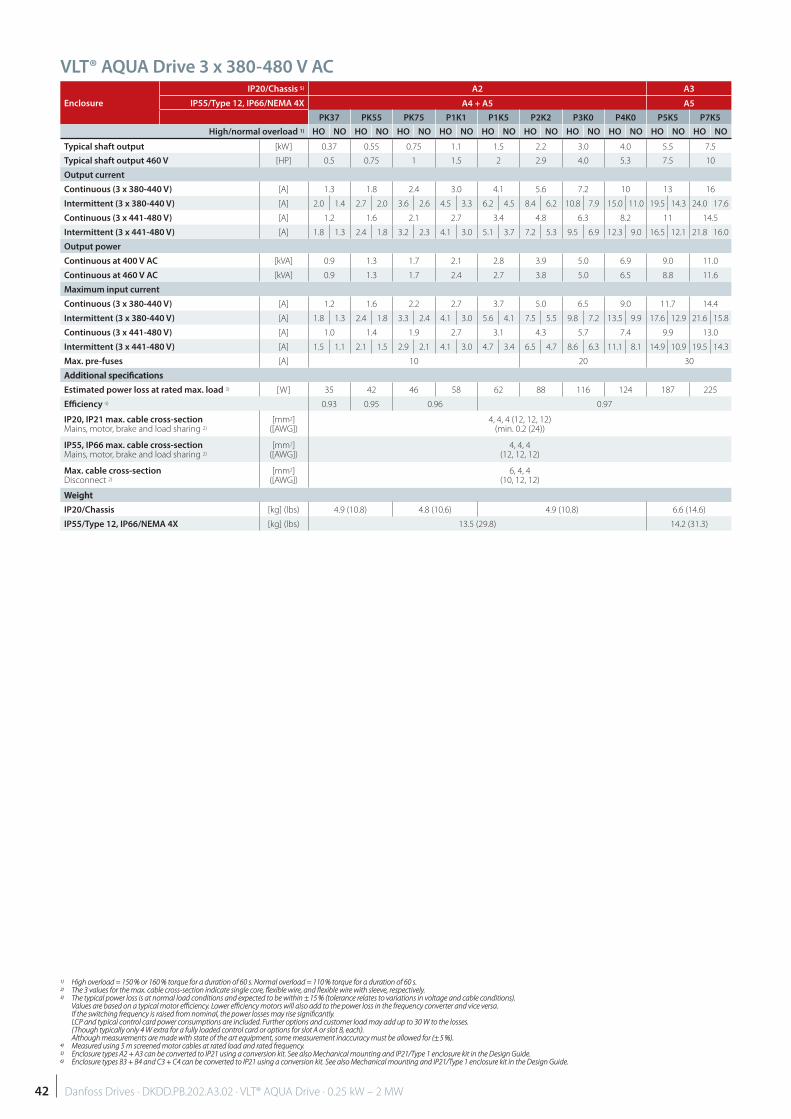
VLT® AQUA Drive 3 x 380-480 V AC
Enclosure
IP20/Chassis 5) A2 A3
IP55/Type 12, IP66/NEMA 4X A4 + A5 A5
PK37 PK55 PK75 P1K1 P1K5 P2K2 P3K0 P4K0 P5K5 P7K5
High/normal overload 1) HO NO HO NO HO NO HO NO HO NO HO NO HO NO HO NO HO NO HO NO
Typical shaft output [kW] 0.37 0.55 0.75 1.1 1.5 2.2 3.0 4.0 5.5 7.5
Typical shaft output 460 V [HP] 0.5 0.75 1 1.5 2 2.9 4.0 5.3 7.5 10
Output current
Continuous (3 x 380-440 V) [A] 1.3 1.8 2.4 3.0 4.1 5.6 7.2 10 13 16
Intermittent (3 x 380-440 V) [A] 2.0 1.4 2.7 2.0 3.6 2.6 4.5 3.3 6.2 4.5 8.4 6.2 10.8 7.9 15.0 11.0 19.5 14.3 24.0 17.6
Continuous (3 x 441-480 V) [A] 1.2 1.6 2.1 2.7 3.4 4.8 6.3 8.2 11 14.5
Intermittent (3 x 441-480 V) [A] 1.8 1.3 2.4 1.8 3.2 2.3 4.1 3.0 5.1 3.7 7.2 5.3 9.5 6.9 12.3 9.0 16.5 12.1 21.8 16.0
Output power
Continuous at 400 V AC [kVA] 0.9 1.3 1.7 2.1 2.8 3.9 5.0 6.9 9.0 11.0
Continuous at 460 V AC [kVA] 0.9 1.3 1.7 2.4 2.7 3.8 5.0 6.5 8.8 11.6
Maximum input current
Continuous (3 x 380-440 V) [A] 1.2 1.6 2.2 2.7 3.7 5.0 6.5 9.0 11.7 14.4
Intermittent (3 x 380-440 V) [A] 1.8 1.3 2.4 1.8 3.3 2.4 4.1 3.0 5.6 4.1 7.5 5.5 9.8 7.2 13.5 9.9 17.6 12.9 21.6 15.8
Continuous (3 x 441-480 V) [A] 1.0 1.4 1.9 2.7 3.1 4.3 5.7 7.4 9.9 13.0
Intermittent (3 x 441-480 V) [A] 1.5 1.1 2.1 1.5 2.9 2.1 4.1 3.0 4.7 3.4 6.5 4.7 8.6 6.3 11.1 8.1 14.9 10.9 19.5 14.3
Max. pre-fuses [A] 10 20 30
Additional specifi cationsAdditional specifi cations
Estimated power loss at rated max. load 3) [W] 35 42 46 58 62 88 116 124 187 225
Effi ciency 4) 0.93 0.95 0.96 0.97
IP20, IP21 max. cable cross-section Mains, motor, brake and load sharing 2)
[mm2]([AWG])
4, 4, 4 (12, 12, 12)(min. 0.2 (24))
IP55, IP66 max. cable cross-section Mains, motor, brake and load sharing 2)
[mm2]([AWG])
4, 4, 4(12, 12, 12)
Max. cable cross-section Disconnect 2)
[mm2]([AWG])
6, 4, 4 (10, 12, 12)
WeightWeight
IP20/Chassis [kg] (lbs) 4.9 (10.8) 4.8 (10.6) 4.9 (10.8) 6.6 (14.6)
IP55/Type 12, IP66/NEMA 4X [kg] (lbs) 13.5 (29.8) 14.2 (31.3)
1)1) High overload = 150 % or 160 % torque for a duration of 60 s. Normal overload = 110 % torque for a duration of 60 s. High overload = 150 % or 160 % torque for a duration of 60 s. Normal overload = 110 % torque for a duration of 60 s.2)2) The 3 values for the max. cable cross-section indicate single core, fl exible wire, and fl exible wire with sleeve, respectively. The 3 values for the max. cable cross-section indicate single core, fl exible wire, and fl exible wire with sleeve, respectively.3)3) The typical power loss is at normal load conditions and expected to be within ± 15 % (tolerance relates to variations in voltage and cable conditions). The typical power loss is at normal load conditions and expected to be within ± 15 % (tolerance relates to variations in voltage and cable conditions).
Values are based on a typical motor effi ciency. Lower effi ciency motors will also add to the power loss in the frequency converter and vice versa.Values are based on a typical motor effi ciency. Lower effi ciency motors will also add to the power loss in the frequency converter and vice versa.If the switching frequency is raised from nominal, the power losses may rise signifi cantly. If the switching frequency is raised from nominal, the power losses may rise signifi cantly. LCP and typical control card power consumptions are included. Further options and customer load may add up to 30 W to the losses. LCP and typical control card power consumptions are included. Further options and customer load may add up to 30 W to the losses. (Though typically only 4 W extra for a fully loaded control card or options for slot A or slot B, each).(Though typically only 4 W extra for a fully loaded control card or options for slot A or slot B, each).Although measurements are made with state of the art equipment, some measurement inaccuracy must be allowed for (± 5 %).Although measurements are made with state of the art equipment, some measurement inaccuracy must be allowed for (± 5 %).
4)4) Measured using 5 m screened motor cables at rated load and rated frequency. Measured using 5 m screened motor cables at rated load and rated frequency.5)5) Enclosure types A2 + A3 can be converted to IP21 using a conversion kit. See also Mechanical mounting and IP21/Type 1 enclosure kit in the Design Guide. Enclosure types A2 + A3 can be converted to IP21 using a conversion kit. See also Mechanical mounting and IP21/Type 1 enclosure kit in the Design Guide.6)6) Enclosure types B3 + B4 and C3 + C4 can be converted to IP21 using a conversion kit. See also Mechanical mounting and IP21/Type 1 enclosure kit in the Design Guide. Enclosure types B3 + B4 and C3 + C4 can be converted to IP21 using a conversion kit. See also Mechanical mounting and IP21/Type 1 enclosure kit in the Design Guide.
42 Danfoss Drives · DKDD.PB.202.A3.02 · VLT® AQUA Drive · 0.25 kW – 2 MW
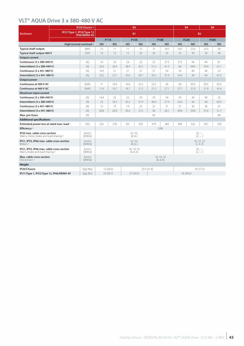
VLT® AQUA Drive 3 x 380-480 V AC
Enclosure
IP20/Chassis 6) B3 B4 B4
IP21/Type 1, IP55/Type 12IP66/NEMA 4X
B1 B2
P11K P15K P18K P22K P30K
High/normal overload 1) HO NO HO NO HO NO HO NO HO NO
Typical shaft output [kW] 7.5 11 11 15 15 18.5 18.5 22.0 22.0 30
Typical shaft output 460 V [HP] 10 15 15 20 20 25 25 30 30 40
Output current
Continuous (3 x 380-440 V) [A] 16 24 24 32 32 37.5 37.5 44 44 61
Intermittent (3 x 380-440 V) [A] 25.6 26.4 38.4 35.2 51.2 41.3 60 48.4 70.4 67.1
Continuous (3 x 441-480 V) [A] 14.5 21 21 27 27 34 34 40 40 52
Intermittent (3 x 441-480 V) [A] 23.2 23.1 33.6 29.7 43.2 37.4 54.4 44 64 61.6
Output power
Continuous at 400 V AC [kVA] 11 16.6 16.6 22.2 22.2 26 26 30.5 30.5 42.3
Continuous at 460 V AC [kVA] 11.6 16.7 16.7 21.5 21.5 27.1 27.1 31.9 31.9 41.4
Maximum input current
Continuous (3 x 380-440 V) [A] 14.4 22 22 29 29 34 34 40 40 55
Intermittent (3 x 380-440 V) [A] 23 24.2 35.2 31.9 46.4 37.4 54.4 44 64 60.5
Continuous (3 x 441-480 V) [A] 13 19 19 25 25 31 31 36 36 47
Intermittent (3 x 441-480 V) [A] 20.8 20.9 30.4 27.5 40 34.1 49.6 39.6 57.6 51.7
Max. pre-fuses [A] 63 80
Additional specifi cationsAdditional specifi cations
Estimated power loss at rated max. load 3) [W] 225 278 291 392 379 465 444 525 547 739
Effi ciency 4) 0.98
IP20 max. cable cross-section Mains, motor, brake and load sharing 2)
[mm2]([AWG])
10, 10,-(8, 8,-)
35, -, -(2, -, -)
IP21, IP55, IP66 max. cable cross-section Motor 2)
[mm2]([AWG])
10, 10,-(8, 8,-)
35, 25, 25(2, 4, 4)
IP21, IP55, IP66 max. cable cross-section Mains, brake and load sharing 2)
[mm2]([AWG])
16, 10, 16(6, 8, 6)
35, -, -(2, -, -)
Max. cable cross-section Disconnect 2)
[mm2]([AWG])
16, 10, 10(6, 8, 8)
WeightWeight
IP20/Chassis [kg] (lbs) 12 (26.5) 23.5 (51.8) 35 (77.2)
IP21/Type 1, IP55/Type 12, IP66/NEMA 4X [kg] (lbs) 23 (50.7) 27 (59.5) 45 (99.2)
43Danfoss Drives · DKDD.PB.202.A3.02 · VLT® AQUA Drive · 0.25 kW – 2 MW
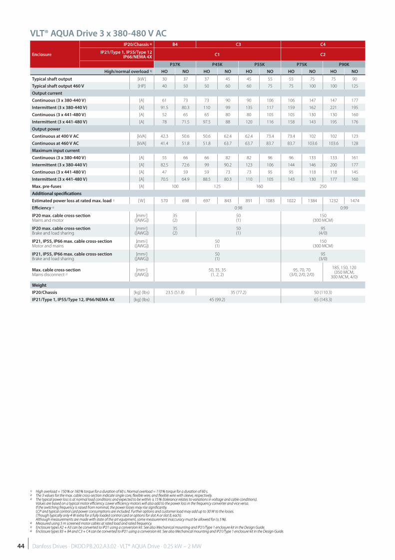
VLT® AQUA Drive 3 x 380-480 V AC
Enclosure
IP20/Chassis 6) B4 C3 C4
IP21/Type 1, IP55/Type 12IP66/NEMA 4X
C1 C2
P37K P45K P55K P75K P90K
High/normal overload 1) HO NO HO NO HO NO HO NO HO NO
Typical shaft output [kW] 30 37 37 45 45 55 55 75 75 90
Typical shaft output 460 V [HP] 40 50 50 60 60 75 75 100 100 125
Output current
Continuous (3 x 380-440 V) [A] 61 73 73 90 90 106 106 147 147 177
Intermittent (3 x 380-440 V) [A] 91.5 80.3 110 99 135 117 159 162 221 195
Continuous (3 x 441-480 V) [A] 52 65 65 80 80 105 105 130 130 160
Intermittent (3 x 441-480 V) [A] 78 71.5 97.5 88 120 116 158 143 195 176
Output power
Continuous at 400 V AC [kVA] 42.3 50.6 50.6 62.4 62.4 73.4 73.4 102 102 123
Continuous at 460 V AC [kVA] 41.4 51.8 51.8 63.7 63.7 83.7 83.7 103.6 103.6 128
Maximum input current
Continuous (3 x 380-440 V) [A] 55 66 66 82 82 96 96 133 133 161
Intermittent (3 x 380-440 V) [A] 82.5 72.6 99 90.2 123 106 144 146 200 177
Continuous (3 x 441-480 V) [A] 47 59 59 73 73 95 95 118 118 145
Intermittent (3 x 441-480 V) [A] 70.5 64.9 88.5 80.3 110 105 143 130 177 160
Max. pre-fuses [A] 100 125 160 250
Additional specifi cationsAdditional specifi cations
Estimated power loss at rated max. load 3) [W] 570 698 697 843 891 1083 1022 1384 1232 1474
Effi ciency 4) 0.98 0.99
IP20 max. cable cross-section Mains and motor
[mm2]([AWG])
35(2)
50(1)
150(300 MCM)
IP20 max. cable cross-section Brake and load sharing
[mm2]([AWG])
35(2)
50(1)
95(4/0)
IP21, IP55, IP66 max. cable cross-section Motor and mains
[mm2]([AWG])
50(1)
150(300 MCM)
IP21, IP55, IP66 max. cable cross-section Brake and load sharing
[mm2]([AWG])
50(1)
95(3/0)
Max. cable cross-section Mains disconnect 2)
[mm2]([AWG])
50, 35, 35(1, 2, 2)
95, 70, 70(3/0, 2/0, 2/0)
185, 150, 120(350 MCM,
300 MCM, 4/0)
WeightWeight
IP20/Chassis [kg] (lbs) 23.5 (51.8) 35 (77.2) 50 (110.3)
IP21/Type 1, IP55/Type 12, IP66/NEMA 4X [kg] (lbs) 45 (99.2) 65 (143.3)
1)1) High overload = 150 % or 160 % torque for a duration of 60 s. Normal overload = 110 % torque for a duration of 60 s. High overload = 150 % or 160 % torque for a duration of 60 s. Normal overload = 110 % torque for a duration of 60 s.2)2) The 3 values for the max. cable cross-section indicate single core, fl exible wire, and fl exible wire with sleeve, respectively. The 3 values for the max. cable cross-section indicate single core, fl exible wire, and fl exible wire with sleeve, respectively.3)3) The typical power loss is at normal load conditions and expected to be within ± 15 % (tolerance relates to variations in voltage and cable conditions). The typical power loss is at normal load conditions and expected to be within ± 15 % (tolerance relates to variations in voltage and cable conditions).
Values are based on a typical motor effi ciency. Lower effi ciency motors will also add to the power loss in the frequency converter and vice versa.Values are based on a typical motor effi ciency. Lower effi ciency motors will also add to the power loss in the frequency converter and vice versa.If the switching frequency is raised from nominal, the power losses may rise signifi cantly. If the switching frequency is raised from nominal, the power losses may rise signifi cantly. LCP and typical control card power consumptions are included. Further options and customer load may add up to 30 W to the losses. LCP and typical control card power consumptions are included. Further options and customer load may add up to 30 W to the losses. (Though typically only 4 W extra for a fully loaded control card or options for slot A or slot B, each).(Though typically only 4 W extra for a fully loaded control card or options for slot A or slot B, each).Although measurements are made with state of the art equipment, some measurement inaccuracy must be allowed for (± 5 %).Although measurements are made with state of the art equipment, some measurement inaccuracy must be allowed for (± 5 %).
4)4) Measured using 5 m screened motor cables at rated load and rated frequency. Measured using 5 m screened motor cables at rated load and rated frequency.5)5) Enclosure types A2 + A3 can be converted to IP21 using a conversion kit. See also Mechanical mounting and IP21/Type 1 enclosure kit in the Design Guide. Enclosure types A2 + A3 can be converted to IP21 using a conversion kit. See also Mechanical mounting and IP21/Type 1 enclosure kit in the Design Guide.6)6) Enclosure types B3 + B4 and C3 + C4 can be converted to IP21 using a conversion kit. See also Mechanical mounting and IP21/Type 1 enclosure kit in the Design Guide. Enclosure types B3 + B4 and C3 + C4 can be converted to IP21 using a conversion kit. See also Mechanical mounting and IP21/Type 1 enclosure kit in the Design Guide.
44 Danfoss Drives · DKDD.PB.202.A3.02 · VLT® AQUA Drive · 0.25 kW – 2 MW
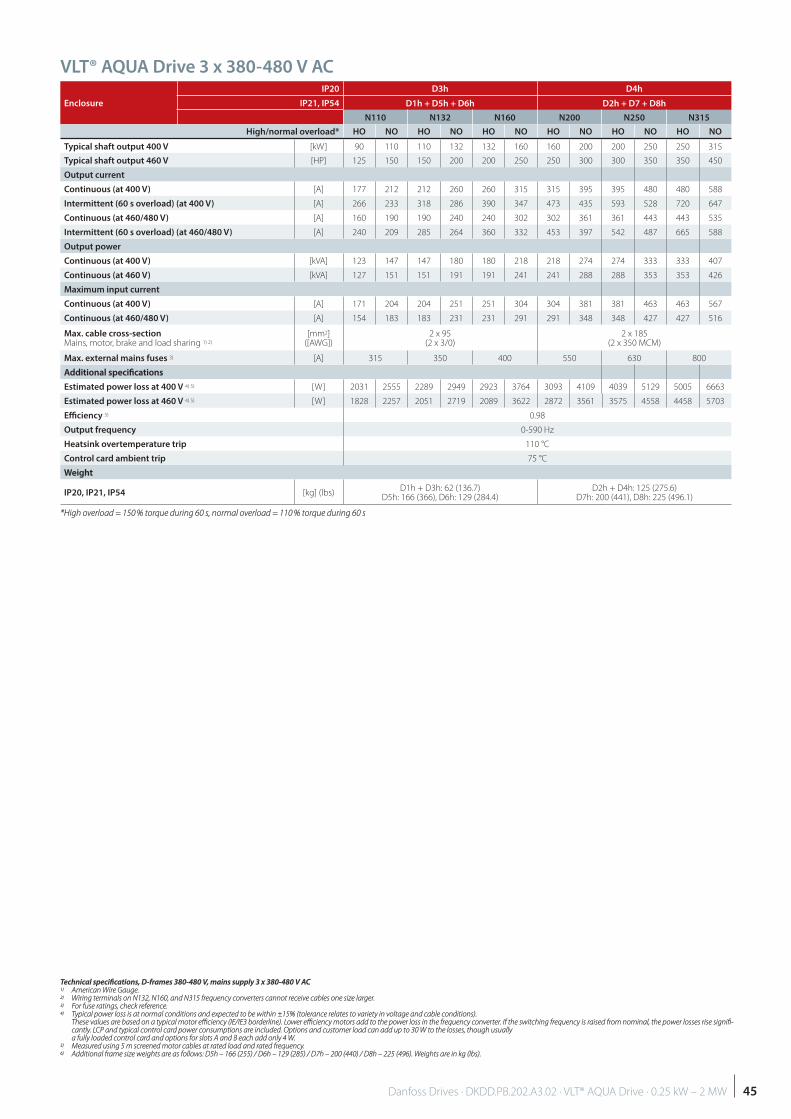
Enclosure
IP20 D3h D4h
IP21, IP54 D1h + D5h + D6h D2h + D7 + D8h
N110 N132 N160 N200 N250 N315
High/normal overload* HO NO HO NO HO NO HO NO HO NO HO NO
Typical shaft output 400 V [kW] 90 110 110 132 132 160 160 200 200 250 250 315
Typical shaft output 460 V [HP] 125 150 150 200 200 250 250 300 300 350 350 450
Output current
Continuous (at 400 V) [A] 177 212 212 260 260 315 315 395 395 480 480 588
Intermittent (60 s overload) (at 400 V) [A] 266 233 318 286 390 347 473 435 593 528 720 647
Continuous (at 460/480 V) [A] 160 190 190 240 240 302 302 361 361 443 443 535
Intermittent (60 s overload) (at 460/480 V) [A] 240 209 285 264 360 332 453 397 542 487 665 588
Output power
Continuous (at 400 V) [kVA] 123 147 147 180 180 218 218 274 274 333 333 407
Continuous (at 460 V) [kVA] 127 151 151 191 191 241 241 288 288 353 353 426
Maximum input current
Continuous (at 400 V) [A] 171 204 204 251 251 304 304 381 381 463 463 567
Continuous (at 460/480 V) [A] 154 183 183 231 231 291 291 348 348 427 427 516
Max. cable cross-section Mains, motor, brake and load sharing 1) 2)
[mm2]([AWG])
2 x 95(2 x 3/0)
2 x 185 (2 x 350 MCM)
Max. external mains fuses 3) [A] 315 350 400 550 630 800
Additional specifi cationsAdditional specifi cations
Estimated power loss at 400 V 4) 5) [W] 2031 2555 2289 2949 2923 3764 3093 4109 4039 5129 5005 6663
Estimated power loss at 460 V 4) 5) [W] 1828 2257 2051 2719 2089 3622 2872 3561 3575 4558 4458 5703
Effi ciency 5) 0.98
Output frequency 0-590 Hz
Heatsink overtemperature trip 110 °C
Control card ambient trip 75 °C
WeightWeight
IP20, IP21, IP54 [kg] (lbs)D1h + D3h: 62 (136.7)
D5h: 166 (366), D6h: 129 (284.4)D2h + D4h: 125 (275.6)
D7h: 200 (441), D8h: 225 (496.1)
*High overload = 150 % torque during 60 s, normal overload = 110 % torque during 60 s*High overload = 150 % torque during 60 s, normal overload = 110 % torque during 60 s
VLT® AQUA Drive 3 x 380-480 V AC
Technical specifi cations, D-frames 380-480 V, mains supply 3 x 380-480 V ACTechnical specifi cations, D-frames 380-480 V, mains supply 3 x 380-480 V AC1)1) American Wire Gauge. American Wire Gauge.2)2) Wiring terminals on N132, N160, and N315 frequency converters cannot receive cables one size larger. Wiring terminals on N132, N160, and N315 frequency converters cannot receive cables one size larger.3)3) For fuse ratings, check reference. For fuse ratings, check reference.4)4) Typical power loss is at normal conditions and expected to be within ±15% (tolerance relates to variety in voltage and cable conditions). Typical power loss is at normal conditions and expected to be within ±15% (tolerance relates to variety in voltage and cable conditions).
These values are based on a typical motor effi ciency (IE/IE3 borderline). Lower effi ciency motors add to the power loss in the frequency converter. If the switching frequency is raised from nominal, the power losses rise signifi -These values are based on a typical motor effi ciency (IE/IE3 borderline). Lower effi ciency motors add to the power loss in the frequency converter. If the switching frequency is raised from nominal, the power losses rise signifi -cantly. LCP and typical control card power consumptions are included. Options and customer load can add up to 30 W to the losses, though usually cantly. LCP and typical control card power consumptions are included. Options and customer load can add up to 30 W to the losses, though usually a fully loaded control card and options for slots A and B each add only 4 W.a fully loaded control card and options for slots A and B each add only 4 W.
5)5) Measured using 5 m screened motor cables at rated load and rated frequency. Measured using 5 m screened motor cables at rated load and rated frequency.6)6) Additional frame size weights are as follows: D5h – 166 (255) / D6h – 129 (285) / D7h – 200 (440) / D8h – 225 (496). Weights are in kg (lbs). Additional frame size weights are as follows: D5h – 166 (255) / D6h – 129 (285) / D7h – 200 (440) / D8h – 225 (496). Weights are in kg (lbs).
45Danfoss Drives · DKDD.PB.202.A3.02 · VLT® AQUA Drive · 0.25 kW – 2 MW
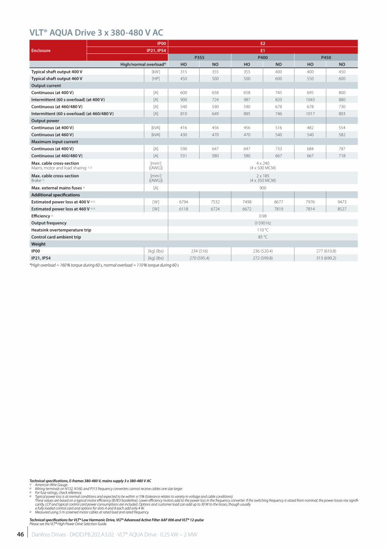
Enclosure
IP00 E2
IP21, IP54 E1
P355 P400 P450
High/normal overload* HO NO HO NO HO NO
Typical shaft output 400 V [kW] 315 355 355 400 400 450
Typical shaft output 460 V [HP] 450 500 500 600 550 600
Output current
Continuous (at 400 V) [A] 600 658 658 745 695 800
Intermittent (60 s overload) (at 400 V) [A] 900 724 987 820 1043 880
Continuous (at 460/480 V) [A] 540 590 590 678 678 730
Intermittent (60 s overload) (at 460/480 V) [A] 810 649 885 746 1017 803
Output power
Continuous (at 400 V) [kVA] 416 456 456 516 482 554
Continuous (at 460 V) [kVA] 430 470 470 540 540 582
Maximum input current
Continuous (at 400 V) [A] 590 647 647 733 684 787
Continuous (at 460/480 V) [A] 531 580 580 667 667 718
Max. cable cross-section Mains, motor and load sharing 1) 2)
[mm2]([AWG])
4 x 240 (4 x 500 MCM)
Max. cable cross-section Brake 1)
[mm2]([AWG])
2 x 185 (4 x 350 MCM)
Max. external mains fuses 3) [A] 900
Additional specifi cationsAdditional specifi cations
Estimated power loss at 400 V 4) 5) [W] 6794 7532 7498 8677 7976 9473
Estimated power loss at 460 V 4) 5) [W] 6118 6724 6672 7819 7814 8527
Effi ciency 5) 0.98
Output frequency 0-590 Hz
Heatsink overtemperature trip 110 °C
Control card ambient trip 85 °C
WeightWeight
IP00 [kg] (lbs) 234 (516) 236 (520.4) 277 (610.8)
IP21, IP54 [kg] (lbs) 270 (595.4) 272 (599.8) 313 (690.2)
*High overload = 160 % torque during 60 s, normal overload = 110 % torque during 60 s*High overload = 160 % torque during 60 s, normal overload = 110 % torque during 60 s
VLT® AQUA Drive 3 x 380-480 V AC
Technical specifi cations, E-frames 380-480 V, mains supply 3 x 380-480 V ACTechnical specifi cations, E-frames 380-480 V, mains supply 3 x 380-480 V AC1)1) American Wire Gauge. American Wire Gauge.2)2) Wiring terminals on N132, N160, and P315 frequency converters cannot receive cables one size larger. Wiring terminals on N132, N160, and P315 frequency converters cannot receive cables one size larger.3)3) For fuse ratings, check reference. For fuse ratings, check reference.4)4) Typical power loss is at normal conditions and expected to be within ±15% (tolerance relates to variety in voltage and cable conditions). Typical power loss is at normal conditions and expected to be within ±15% (tolerance relates to variety in voltage and cable conditions).
These values are based on a typical motor effi ciency (IE/IE3 borderline). Lower effi ciency motors add to the power loss in the frequency converter. If the switching frequency is raised from nominal, the power losses rise signifi -These values are based on a typical motor effi ciency (IE/IE3 borderline). Lower effi ciency motors add to the power loss in the frequency converter. If the switching frequency is raised from nominal, the power losses rise signifi -cantly. LCP and typical control card power consumptions are included. Options and customer load can add up to 30 W to the losses, though usually cantly. LCP and typical control card power consumptions are included. Options and customer load can add up to 30 W to the losses, though usually a fully loaded control card and options for slots A and B each add only 4 W.a fully loaded control card and options for slots A and B each add only 4 W.
5)5) Measured using 5 m screened motor cables at rated load and rated frequency. Measured using 5 m screened motor cables at rated load and rated frequency.
Technical specifi cations for VLT® Low Harmonic Drive, VLT® Advanced Active Filter AAF 006 and VLT® 12-pulseTechnical specifi cations for VLT® Low Harmonic Drive, VLT® Advanced Active Filter AAF 006 and VLT® 12-pulsePlease see the VLT® High Power Drive Selection Guide.Please see the VLT® High Power Drive Selection Guide.
46 Danfoss Drives · DKDD.PB.202.A3.02 · VLT® AQUA Drive · 0.25 kW – 2 MW
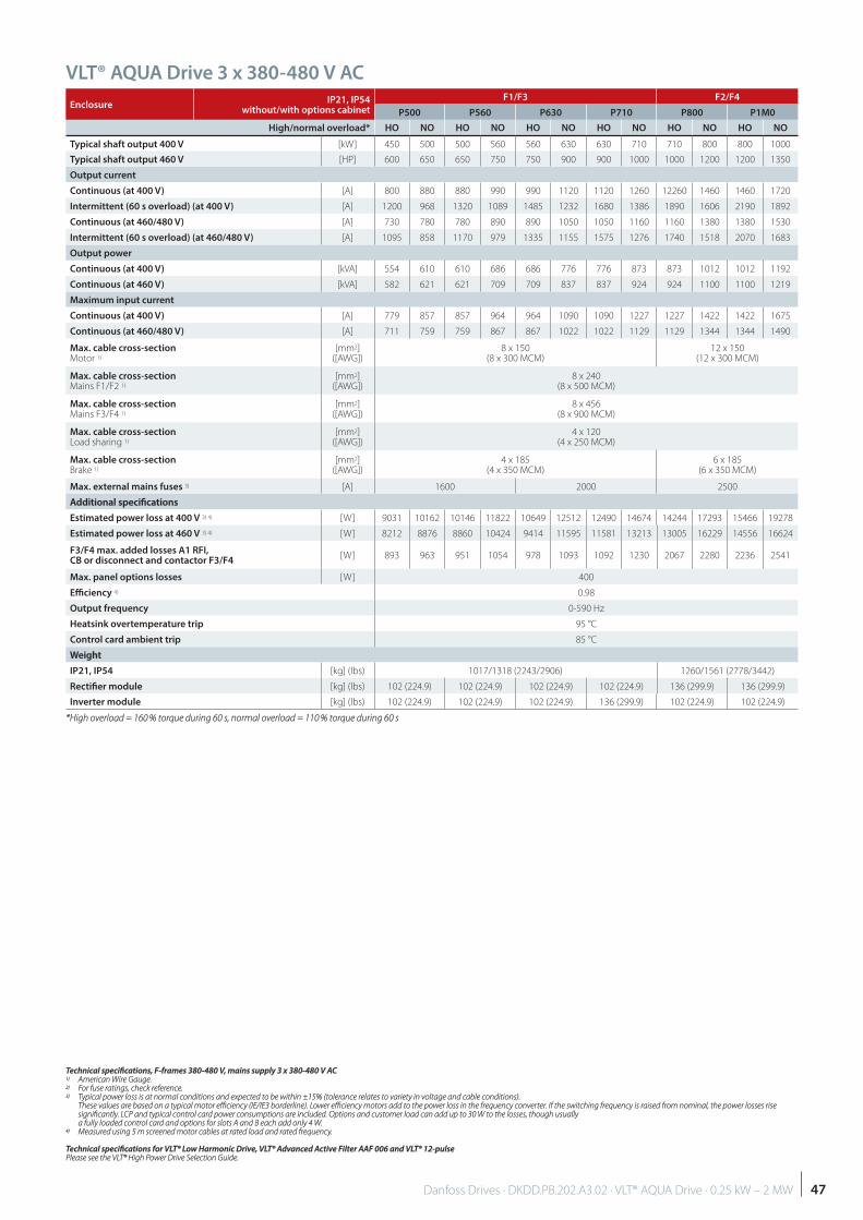
EnclosureIP21, IP54
without/with options cabinet
F1/F3 F2/F4
P500 P560 P630 P710 P800 P1M0
High/normal overload* HO NO HO NO HO NO HO NO HO NO HO NO
Typical shaft output 400 V [kW] 450 500 500 560 560 630 630 710 710 800 800 1000
Typical shaft output 460 V [HP] 600 650 650 750 750 900 900 1000 1000 1200 1200 1350
Output current
Continuous (at 400 V) [A] 800 880 880 990 990 1120 1120 1260 12260 1460 1460 1720
Intermittent (60 s overload) (at 400 V) [A] 1200 968 1320 1089 1485 1232 1680 1386 1890 1606 2190 1892
Continuous (at 460/480 V) [A] 730 780 780 890 890 1050 1050 1160 1160 1380 1380 1530
Intermittent (60 s overload) (at 460/480 V) [A] 1095 858 1170 979 1335 1155 1575 1276 1740 1518 2070 1683
Output power
Continuous (at 400 V) [kVA] 554 610 610 686 686 776 776 873 873 1012 1012 1192
Continuous (at 460 V) [kVA] 582 621 621 709 709 837 837 924 924 1100 1100 1219
Maximum input current
Continuous (at 400 V) [A] 779 857 857 964 964 1090 1090 1227 1227 1422 1422 1675
Continuous (at 460/480 V) [A] 711 759 759 867 867 1022 1022 1129 1129 1344 1344 1490
Max. cable cross-section Motor 1)
[mm2]([AWG])
8 x 150 (8 x 300 MCM)
12 x 150 (12 x 300 MCM)
Max. cable cross-section Mains F1/F2 1)
[mm2]([AWG])
8 x 240 (8 x 500 MCM)
Max. cable cross-section Mains F3/F4 1)
[mm2]([AWG])
8 x 456 (8 x 900 MCM)
Max. cable cross-section Load sharing 1)
[mm2]([AWG])
4 x 120 (4 x 250 MCM)
Max. cable cross-section Brake 1)
[mm2]([AWG])
4 x 185 (4 x 350 MCM)
6 x 185 (6 x 350 MCM)
Max. external mains fuses 3) [A] 1600 2000 2500
Additional specifi cationsAdditional specifi cations
Estimated power loss at 400 V 3) 4) [W] 9031 10162 10146 11822 10649 12512 12490 14674 14244 17293 15466 19278
Estimated power loss at 460 V 3) 4) [W] 8212 8876 8860 10424 9414 11595 11581 13213 13005 16229 14556 16624
F3/F4 max. added losses A1 RFI, CB or disconnect and contactor F3/F4
[W] 893 963 951 1054 978 1093 1092 1230 2067 2280 2236 2541
Max. panel options losses [W] 400
Effi ciency 4) 0.98
Output frequency 0-590 Hz
Heatsink overtemperature trip 95 °C
Control card ambient trip 85 °C
WeightWeight
IP21, IP54 [kg] (lbs) 1017/1318 (2243/2906) 1260/1561 (2778/3442)
Rectifi er module [kg] (lbs) 102 (224.9) 102 (224.9) 102 (224.9) 102 (224.9) 136 (299.9) 136 (299.9)
Inverter module [kg] (lbs) 102 (224.9) 102 (224.9) 102 (224.9) 136 (299.9) 102 (224.9) 102 (224.9)
*High overload = 160 % torque during 60 s, normal overload = 110 % torque during 60 s*High overload = 160 % torque during 60 s, normal overload = 110 % torque during 60 s
VLT® AQUA Drive 3 x 380-480 V AC
Technical specifi cations, F-frames 380-480 V, mains supply 3 x 380-480 V ACTechnical specifi cations, F-frames 380-480 V, mains supply 3 x 380-480 V AC1)1) American Wire Gauge. American Wire Gauge.2)2) For fuse ratings, check reference. For fuse ratings, check reference.3)3) Typical power loss is at normal conditions and expected to be within ±15% (tolerance relates to variety in voltage and cable conditions). Typical power loss is at normal conditions and expected to be within ±15% (tolerance relates to variety in voltage and cable conditions).
These values are based on a typical motor effi ciency (IE/IE3 borderline). Lower effi ciency motors add to the power loss in the frequency converter. If the switching frequency is raised from nominal, the power losses rise These values are based on a typical motor effi ciency (IE/IE3 borderline). Lower effi ciency motors add to the power loss in the frequency converter. If the switching frequency is raised from nominal, the power losses rise signifi cantly. LCP and typical control card power consumptions are included. Options and customer load can add up to 30 W to the losses, though usually signifi cantly. LCP and typical control card power consumptions are included. Options and customer load can add up to 30 W to the losses, though usually a fully loaded control card and options for slots A and B each add only 4 W.a fully loaded control card and options for slots A and B each add only 4 W.
4)4) Measured using 5 m screened motor cables at rated load and rated frequency. Measured using 5 m screened motor cables at rated load and rated frequency.
Technical specifi cations for VLT® Low Harmonic Drive, VLT® Advanced Active Filter AAF 006 and VLT® 12-pulseTechnical specifi cations for VLT® Low Harmonic Drive, VLT® Advanced Active Filter AAF 006 and VLT® 12-pulsePlease see the VLT® High Power Drive Selection Guide.Please see the VLT® High Power Drive Selection Guide.
47Danfoss Drives · DKDD.PB.202.A3.02 · VLT® AQUA Drive · 0.25 kW – 2 MW
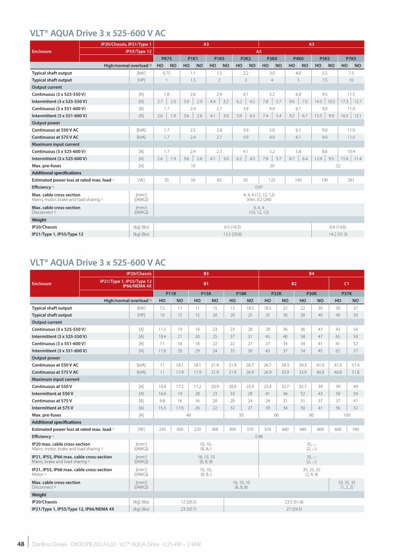
VLT® AQUA Drive 3 x 525-600 V AC
Enclosure
IP20/Chassis, IP21/Type 1 A3 A3
IP55/Type 12 A5
PK75 P1K1 P1K5 P2K2 P3K0 P4K0 P5K5 P7K5
High/normal overload 1) HO NO HO NO HO NO HO NO HO NO HO NO HO NO HO NO
Typical shaft output [kW] 0.75 1.1 1.5 2.2 3.0 4.0 5.5 7.5
Typical shaft output [HP] 1 1.5 2 3 4 5 7.5 10
Output current
Continuous (3 x 525-550 V) [A] 1.8 2.6 2.9 4.1 5.2 6.4 9.5 11.5
Intermittent (3 x 525-550 V) [A] 2.7 2.0 3.9 2.9 4.4 3.2 6.2 4.5 7.8 5.7 9.6 7.0 14.3 10.5 17.3 12.7
Continuous (3 x 551-600 V) [A] 1.7 2.4 2.7 3.9 4.9 6.1 9.0 11.0
Intermittent (3 x 551-600 V) [A] 2.6 1.9 3.6 2.6 4.1 3.0 5.9 4.3 7.4 5.4 9.2 6.7 13.5 9.9 16.5 12.1
Output power
Continuous at 550 V AC [kVA] 1.7 2.5 2.8 3.9 5.0 6.1 9.0 11.0
Continuous at 575 V AC [kVA] 1.7 2.4 2.7 3.9 4.9 6.1 9.0 11.0
Maximum input current
Continuous (3 x 525-600 V) [A] 1.7 2.4 2.7 4.1 5.2 5.8 8.6 10.4
Intermittent (3 x 525-600 V) [A] 2.6 1.9 3.6 2.6 4.1 3.0 6.2 4.5 7.8 5.7 8.7 6.4 12.9 9.5 15.6 11.4
Max. pre-fuses [A] 10 20 32
Additional specifi cationsAdditional specifi cations
Estimated power loss at rated max. load 3) [W] 35 50 65 92 122 145 195 261
Effi ciency 4) 0.97
Max. cable cross-section Mains, motor, brake and load sharing 2)
[mm2]([AWG])
4, 4, 4 (12, 12, 12)(min. 0.2 (24))
Max. cable cross-section Disconnect 2)
[mm2]([AWG])
6, 4, 4(10, 12, 12)
WeightWeight
IP20/Chassis [kg] (lbs) 6.5 (14.3) 6.6 (14.6)
IP21/Type 1, IP55/Type 12 [kg] (lbs) 13.5 (29.8) 14.2 (31.3)
VLT® AQUA Drive 3 x 525-600 V AC
Enclosure
IP20/Chassis B3 B4
IP21/Type 1, IP55/Type 12IP66/NEMA 4X
B1 B2 C1
P11K P15K P18K P22K P30K P37K
High/normal overload 1) HO NO HO NO HO NO HO NO HO NO HO NO
Typical shaft output [kW] 7.5 11 11 15 15 18.5 18.5 22 22 30 30 37
Typical shaft output [HP] 10 15 15 20 20 25 25 30 30 40 40 50
Output current
Continuous (3 x 525-550 V) [A] 11.5 19 19 23 23 28 28 36 36 43 43 54
Intermittent (3 x 525-550 V) [A] 18.4 21 30 25 37 31 45 40 58 47 65 59
Continuous (3 x 551-600 V) [A] 11 18 18 22 22 27 27 34 34 41 41 52
Intermittent (3 x 551-600 V) [A] 17.6 20 29 24 35 30 43 37 54 45 62 57
Output power
Continuous at 550 V AC [kVA] 11 18.1 18.1 21.9 21.9 26.7 26.7 34.3 34.3 41.0 41.0 51.4
Continuous at 575 V AC [kVA] 11 17.9 17.9 21.9 21.9 26.9 26.9 33.9 33.9 40.8 40.8 51.8
Maximum input current
Continuous at 550 V [A] 10.4 17.2 17.2 20.9 20.9 25.4 25.4 32.7 32.7 39 39 49
Intermittent at 550 V [A] 16.6 19 28 23 33 28 41 36 52 43 59 54
Continuous at 575 V [A] 9.8 16 16 20 20 24 24 31 31 37 37 47
Intermittent at 575 V [A] 15.5 17.6 26 22 32 27 39 34 50 41 56 52
Max. pre-fuses [A] 40 50 60 80 100
Additional specifi cationsAdditional specifi cations
Estimated power loss at rated max. load 3) [W] 220 300 220 300 300 370 370 440 440 600 600 740
Effi ciency 4) 0.98
IP20 max. cable cross-section Mains, motor, brake and load sharing 2)
[mm2]([AWG])
10, 10,-(8, 8,-)
35, -,-(2, -,-)
IP21, IP55, IP66 max. cable cross-section Mains, brake and load sharing 2)
[mm2]([AWG])
16, 10, 10(6, 8, 8)
35, -,-(2, -,-)
IP21, IP55, IP66 max. cable cross-section Motor 2)
[mm2]([AWG])
10, 10,-(8, 8,-)
35, 25, 25(2, 4, 4)
Max. cable cross-section Disconnect 2)
[mm2]([AWG])
16, 10, 10(6, 8, 8)
50, 35, 35(1, 2, 2)
WeightWeight
IP20/Chassis [kg] (lbs) 12 (26.5) 23.5 (51.8)
IP21/Type 1, IP55/Type 12, IP66/NEMA 4X [kg] (lbs) 23 (50.7) 27 (59.5)
48 Danfoss Drives · DKDD.PB.202.A3.02 · VLT® AQUA Drive · 0.25 kW – 2 MW
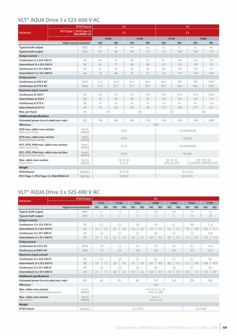
VLT® AQUA Drive 3 x 525-600 V AC
Enclosure
IP20/Chassis C3 C4
IP21/Type 1, IP55/Type 12IP66/NEMA 4X
C1 C2
P45K P55K P75K P90K
High/normal overload 1) HO NO HO NO HO NO HO NO
Typical shaft output [kW] 37 45 45 55 55 75 75 90
Typical shaft output [HP] 50 60 60 75 75 100 100 125
Output current
Continuous (3 x 525-550 V) [A] 54 65 65 87 87 105 105 137
Intermittent (3 x 525-550 V) [A] 81 72 98 96 131 116 158 151
Continuous (3 x 551-600 V) [A] 52 62 62 83 83 100 100 131
Intermittent (3 x 551-600 V) [A] 78 68 93 91 125 110 150 144
Output power
Continuous at 550 V AC [kVA] 51.4 61.9 61.9 82.9 82.9 100 100 130.5
Continuous at 575 V AC [kVA] 51.8 61.7 61.7 82.7 82.7 99.6 99.6 130.5
Maximum input current
Continuous at 550 V [A] 49 59 59 78.9 78.9 95.3 95.3 124.3
Intermittent at 550 V [A] 74 65 89 87 118 105 143 137
Continuous at 575 V [A] 47 56 56 75 75 91 91 119
Intermittent at 575 V [A] 70 62 85 83 113 100 137 131
Max. pre-fuses [A] 150 160 225 250
Additional specifi cationsAdditional specifi cations
Estimated power loss at rated max. load 3) [W] 740 900 900 1100 1100 1500 1500 1800
Effi ciency 4) 0.98
IP20 max. cable cross-section Mains and motor
[mm2]([AWG])
50 (1) 150 (300 MCM)
IP20 max. cable cross-section Brake and load sharing
[mm2]([AWG])
50 (1) 95 (4/0)
IP21, IP55, IP66 max. cable cross-section Mains and motor
[mm2]([AWG])
50 (1) 150 (300 MCM)
IP21, IP55, IP66 max. cable cross-section Brake and load sharing
[mm2]([AWG])
50 (1) 95 (4/0)
Max. cable cross-section Disconnect 2)
[mm2]([AWG])
50, 35, 35(1, 2, 2)
95, 70, 70(3/0, 2/0, 2/0)
185, 150, 120(350 MCM, 300 MCM, 4/0)
WeightWeight
IP20/Chassis [kg] (lbs) 35 (77.2) 50 (110.3)
IP21/Type 1, IP55/Type 12, IP66/NEMA 4X [kg] (lbs) 45 (99.2) 65 (143.3)
VLT® AQUA Drive 3 x 525-690 V AC
EnclosureIP20/Chassis A3
P1K1 P1K5 P2K2 P3K0 P4K0 P5K5 P7K5
High/normal overload 1) HO NO HO NO HO NO HO NO HO NO HO NO HO NO
Typical shaft output [kW] 1.1 1.5 2.2 3.0 4.0 5.5 7.5
Typical shaft output [HP] 1.5 2 3 4 5 7.5 10
Output current
Continuous (3 x 525-550 V) [A] 2.1 2.7 3.9 4.9 6.1 9.0 11.0
Intermittent (3 x 525-550 V) [A] 3.2 2.3 4.1 3.0 5.9 4.3 7.4 5.4 9.2 6.7 13.5 9.9 16.5 12.1
Continuous (3 x 551-690 V) [A] 1.6 2.2 3.2 4.5 5.5 7.5 10.0
Intermittent (3 x 551-690 V) [A] 2.4 1.8 3.3 2.4 4.8 3.5 6.8 5.0 8.3 6.1 11.3 8.3 15.0 11.0
Output power
Continuous at 525 V AC [kVA] 1.9 2.5 3.5 4.5 5.5 8.2 10.0
Continuous at 690 V AC [kVA] 1.9 2.6 3.8 5.4 6.6 9.0 12.0
Maximum input current
Continuous (3 x 525-550 V) [A] 1.9 2.4 3.5 4.4 5.5 8.1 9.9
Intermittent (3 x 525-550 V) [A] 2.9 2.1 3.6 2.6 5.3 3.9 6.6 4.8 8.3 6.1 12.2 8.9 14.9 10.9
Continuous (3 x 551-690 V) [A] 1.4 2.0 2.9 4.0 4.9 6.7 9.0
Intermittent (3 x 551-690 V) [A] 2.1 1.5 3.0 2.2 4.4 3.2 6.0 4.4 7.4 5.4 10.1 7.4 13.5 9.9
Additional specifi cationsAdditional specifi cations
Estimated power loss at rated max. load 3) [W] 44 60 88 120 160 220 300
Effi ciency 4) 0.96
Max. cable cross-section Mains, motor, brake and load sharing 2)
[mm2]([AWG])
4, 4, 4 (12, 12, 12)(min. 0.2 (24)
Max. cable cross-section Disconnect 2)
[mm2]([AWG])
6, 4, 4(10, 12, 12)
WeightWeight
IP20/Chassis [kg] (lbs) 6.5 (14.3) 6.6 (14.6)
49Danfoss Drives · DKDD.PB.202.A3.02 · VLT® AQUA Drive · 0.25 kW – 2 MW
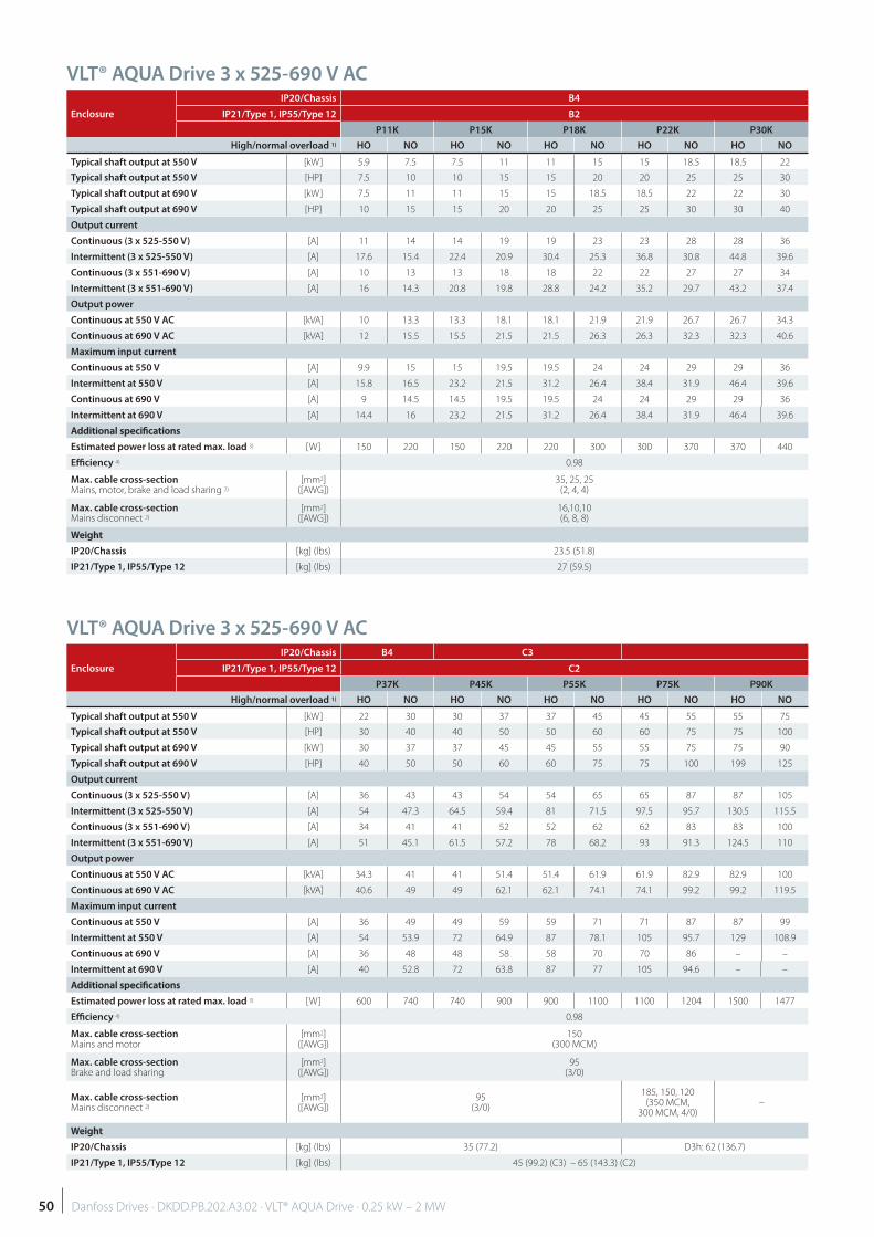
VLT® AQUA Drive 3 x 525-690 V AC
VLT® AQUA Drive 3 x 525-690 V AC
Enclosure
IP20/Chassis B4
IP21/Type 1, IP55/Type 12 B2
P11K P15K P18K P22K P30K
High/normal overload 1) HO NO HO NO HO NO HO NO HO NO
Typical shaft output at 550 V [kW] 5.9 7.5 7.5 11 11 15 15 18.5 18.5 22
Typical shaft output at 550 V [HP] 7.5 10 10 15 15 20 20 25 25 30
Typical shaft output at 690 V [kW] 7.5 11 11 15 15 18.5 18.5 22 22 30
Typical shaft output at 690 V [HP] 10 15 15 20 20 25 25 30 30 40
Output current
Continuous (3 x 525-550 V) [A] 11 14 14 19 19 23 23 28 28 36
Intermittent (3 x 525-550 V) [A] 17.6 15.4 22.4 20.9 30.4 25.3 36.8 30.8 44.8 39.6
Continuous (3 x 551-690 V) [A] 10 13 13 18 18 22 22 27 27 34
Intermittent (3 x 551-690 V) [A] 16 14.3 20.8 19.8 28.8 24.2 35.2 29.7 43.2 37.4
Output power
Continuous at 550 V AC [kVA] 10 13.3 13.3 18.1 18.1 21.9 21.9 26.7 26.7 34.3
Continuous at 690 V AC [kVA] 12 15.5 15.5 21.5 21.5 26.3 26.3 32.3 32.3 40.6
Maximum input current
Continuous at 550 V [A] 9.9 15 15 19.5 19.5 24 24 29 29 36
Intermittent at 550 V [A] 15.8 16.5 23.2 21.5 31.2 26.4 38.4 31.9 46.4 39.6
Continuous at 690 V [A] 9 14.5 14.5 19.5 19.5 24 24 29 29 36
Intermittent at 690 V [A] 14.4 16 23.2 21.5 31.2 26.4 38.4 31.9 46.4 39.6
Additional specifi cationsAdditional specifi cations
Estimated power loss at rated max. load 3) [W] 150 220 150 220 220 300 300 370 370 440
Effi ciency 4) 0.98
Max. cable cross-section Mains, motor, brake and load sharing 2)
[mm2]([AWG])
35, 25, 25(2, 4, 4)
Max. cable cross-section Mains disconnect 2)
[mm2]([AWG])
16,10,10(6, 8, 8)
WeightWeight
IP20/Chassis [kg] (lbs) 23.5 (51.8)
IP21/Type 1, IP55/Type 12 [kg] (lbs) 27 (59.5)
Enclosure
IP20/Chassis B4 C3
IP21/Type 1, IP55/Type 12 C2
P37K P45K P55K P75K P90K
High/normal overload 1) HO NO HO NO HO NO HO NO HO NO
Typical shaft output at 550 V [kW] 22 30 30 37 37 45 45 55 55 75
Typical shaft output at 550 V [HP] 30 40 40 50 50 60 60 75 75 100
Typical shaft output at 690 V [kW] 30 37 37 45 45 55 55 75 75 90
Typical shaft output at 690 V [HP] 40 50 50 60 60 75 75 100 199 125
Output current
Continuous (3 x 525-550 V) [A] 36 43 43 54 54 65 65 87 87 105
Intermittent (3 x 525-550 V) [A] 54 47.3 64.5 59.4 81 71.5 97.5 95.7 130.5 115.5
Continuous (3 x 551-690 V) [A] 34 41 41 52 52 62 62 83 83 100
Intermittent (3 x 551-690 V) [A] 51 45.1 61.5 57.2 78 68.2 93 91.3 124.5 110
Output power
Continuous at 550 V AC [kVA] 34.3 41 41 51.4 51.4 61.9 61.9 82.9 82.9 100
Continuous at 690 V AC [kVA] 40.6 49 49 62.1 62.1 74.1 74.1 99.2 99.2 119.5
Maximum input current
Continuous at 550 V [A] 36 49 49 59 59 71 71 87 87 99
Intermittent at 550 V [A] 54 53.9 72 64.9 87 78.1 105 95.7 129 108.9
Continuous at 690 V [A] 36 48 48 58 58 70 70 86 – –
Intermittent at 690 V [A] 40 52.8 72 63.8 87 77 105 94.6 – –
Additional specifi cationsAdditional specifi cations
Estimated power loss at rated max. load 3) [W] 600 740 740 900 900 1100 1100 1204 1500 1477
Effi ciency 4) 0.98
Max. cable cross-section Mains and motor
[mm2]([AWG])
150(300 MCM)
Max. cable cross-section Brake and load sharing
[mm2]([AWG])
95(3/0)
Max. cable cross-section Mains disconnect 2)
[mm2]([AWG])
95(3/0)
185, 150, 120(350 MCM,
300 MCM, 4/0)–
WeightWeight
IP20/Chassis [kg] (lbs) 35 (77.2) D3h: 62 (136.7)
IP21/Type 1, IP55/Type 12 [kg] (lbs) 45 (99.2) (C3) – 65 (143.3) (C2)
50 Danfoss Drives · DKDD.PB.202.A3.02 · VLT® AQUA Drive · 0.25 kW – 2 MW
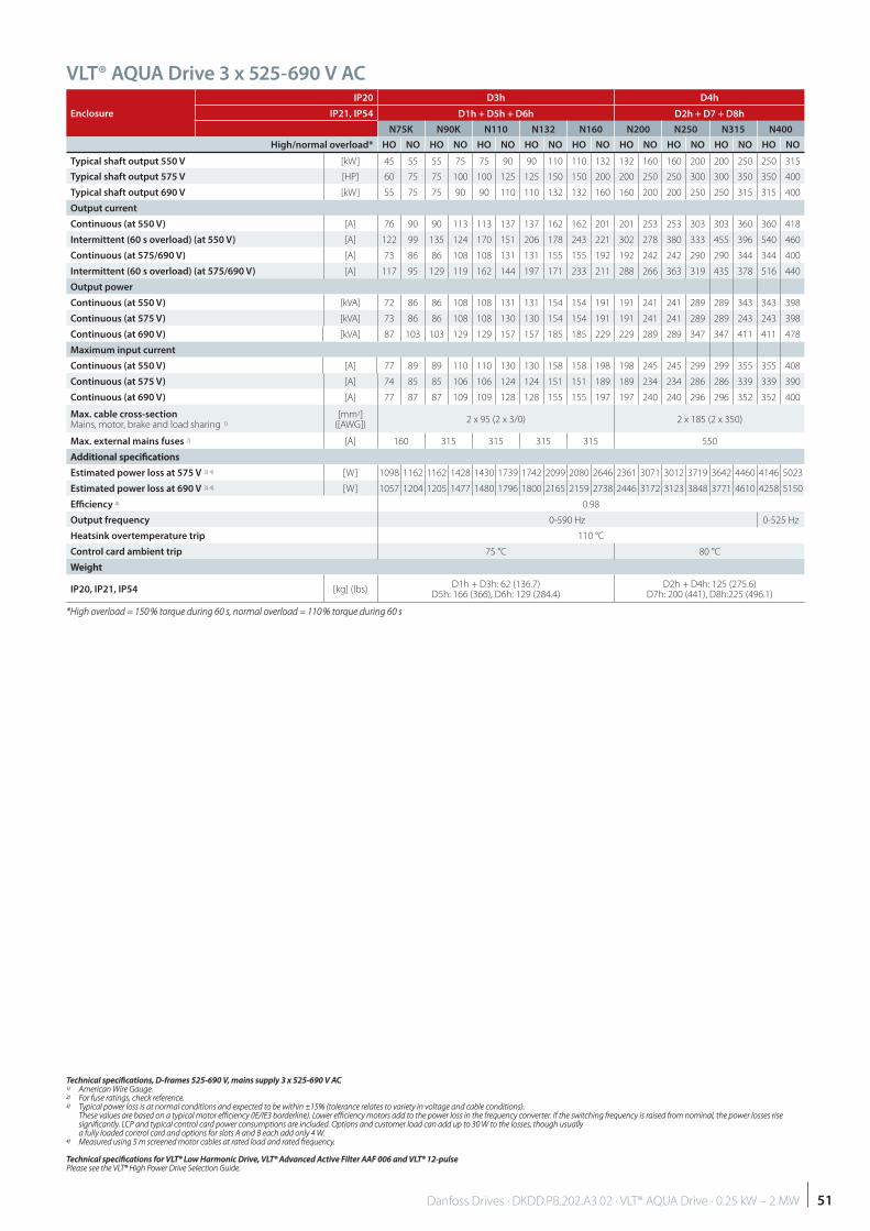
VLT® AQUA Drive 3 x 525-690 V AC
Enclosure
IP20 D3h D4h
IP21, IP54 D1h + D5h + D6h D2h + D7 + D8h
N75K N90K N110 N132 N160 N200 N250 N315 N400
High/normal overload* HO NO HO NO HO NO HO NO HO NO HO NO HO NO HO NO HO NO
Typical shaft output 550 V [kW] 45 55 55 75 75 90 90 110 110 132 132 160 160 200 200 250 250 315
Typical shaft output 575 V [HP] 60 75 75 100 100 125 125 150 150 200 200 250 250 300 300 350 350 400
Typical shaft output 690 V [kW] 55 75 75 90 90 110 110 132 132 160 160 200 200 250 250 315 315 400
Output current
Continuous (at 550 V) [A] 76 90 90 113 113 137 137 162 162 201 201 253 253 303 303 360 360 418
Intermittent (60 s overload) (at 550 V) [A] 122 99 135 124 170 151 206 178 243 221 302 278 380 333 455 396 540 460
Continuous (at 575/690 V) [A] 73 86 86 108 108 131 131 155 155 192 192 242 242 290 290 344 344 400
Intermittent (60 s overload) (at 575/690 V) [A] 117 95 129 119 162 144 197 171 233 211 288 266 363 319 435 378 516 440
Output power
Continuous (at 550 V) [kVA] 72 86 86 108 108 131 131 154 154 191 191 241 241 289 289 343 343 398
Continuous (at 575 V) [kVA] 73 86 86 108 108 130 130 154 154 191 191 241 241 289 289 243 243 398
Continuous (at 690 V) [kVA] 87 103 103 129 129 157 157 185 185 229 229 289 289 347 347 411 411 478
Maximum input current
Continuous (at 550 V) [A] 77 89 89 110 110 130 130 158 158 198 198 245 245 299 299 355 355 408
Continuous (at 575 V) [A] 74 85 85 106 106 124 124 151 151 189 189 234 234 286 286 339 339 390
Continuous (at 690 V) [A] 77 87 87 109 109 128 128 155 155 197 197 240 240 296 296 352 352 400
Max. cable cross-section Mains, motor, brake and load sharing 1)
[mm2]([AWG])
2 x 95 (2 x 3/0) 2 x 185 (2 x 350)
Max. external mains fuses 2) [A] 160 315 315 315 315 550
Additional specifi cationsAdditional specifi cations
Estimated power loss at 575 V 3) 4) [W] 1098 1162 1162 1428 1430 1739 1742 2099 2080 2646 2361 3071 3012 3719 3642 4460 4146 5023
Estimated power loss at 690 V 3) 4) [W] 1057 1204 1205 1477 1480 1796 1800 2165 2159 2738 2446 3172 3123 3848 3771 4610 4258 5150
Effi ciency 4) 0.98
Output frequency 0-590 Hz 0-525 Hz
Heatsink overtemperature trip 110 °C
Control card ambient trip 75 °C 80 °C
WeightWeight
IP20, IP21, IP54 [kg] (lbs)D1h + D3h: 62 (136.7)
D5h: 166 (366), D6h: 129 (284.4)D2h + D4h: 125 (275.6)
D7h: 200 (441), D8h:225 (496.1)
*High overload = 150 % torque during 60 s, normal overload = 110 % torque during 60 s*High overload = 150 % torque during 60 s, normal overload = 110 % torque during 60 s
Technical specifi cations, D-frames 525-690 V, mains supply 3 x 525-690 V ACTechnical specifi cations, D-frames 525-690 V, mains supply 3 x 525-690 V AC1)1) American Wire Gauge. American Wire Gauge.2)2) For fuse ratings, check reference. For fuse ratings, check reference.3)3) Typical power loss is at normal conditions and expected to be within ±15% (tolerance relates to variety in voltage and cable conditions). Typical power loss is at normal conditions and expected to be within ±15% (tolerance relates to variety in voltage and cable conditions).
These values are based on a typical motor effi ciency (IE/IE3 borderline). Lower effi ciency motors add to the power loss in the frequency converter. If the switching frequency is raised from nominal, the power losses rise These values are based on a typical motor effi ciency (IE/IE3 borderline). Lower effi ciency motors add to the power loss in the frequency converter. If the switching frequency is raised from nominal, the power losses rise signifi cantly. LCP and typical control card power consumptions are included. Options and customer load can add up to 30 W to the losses, though usually signifi cantly. LCP and typical control card power consumptions are included. Options and customer load can add up to 30 W to the losses, though usually a fully loaded control card and options for slots A and B each add only 4 W.a fully loaded control card and options for slots A and B each add only 4 W.
4)4) Measured using 5 m screened motor cables at rated load and rated frequency. Measured using 5 m screened motor cables at rated load and rated frequency.
Technical specifi cations for VLT® Low Harmonic Drive, VLT® Advanced Active Filter AAF 006 and VLT® 12-pulseTechnical specifi cations for VLT® Low Harmonic Drive, VLT® Advanced Active Filter AAF 006 and VLT® 12-pulsePlease see the VLT® High Power Drive Selection Guide.Please see the VLT® High Power Drive Selection Guide.
51Danfoss Drives · DKDD.PB.202.A3.02 · VLT® AQUA Drive · 0.25 kW – 2 MW
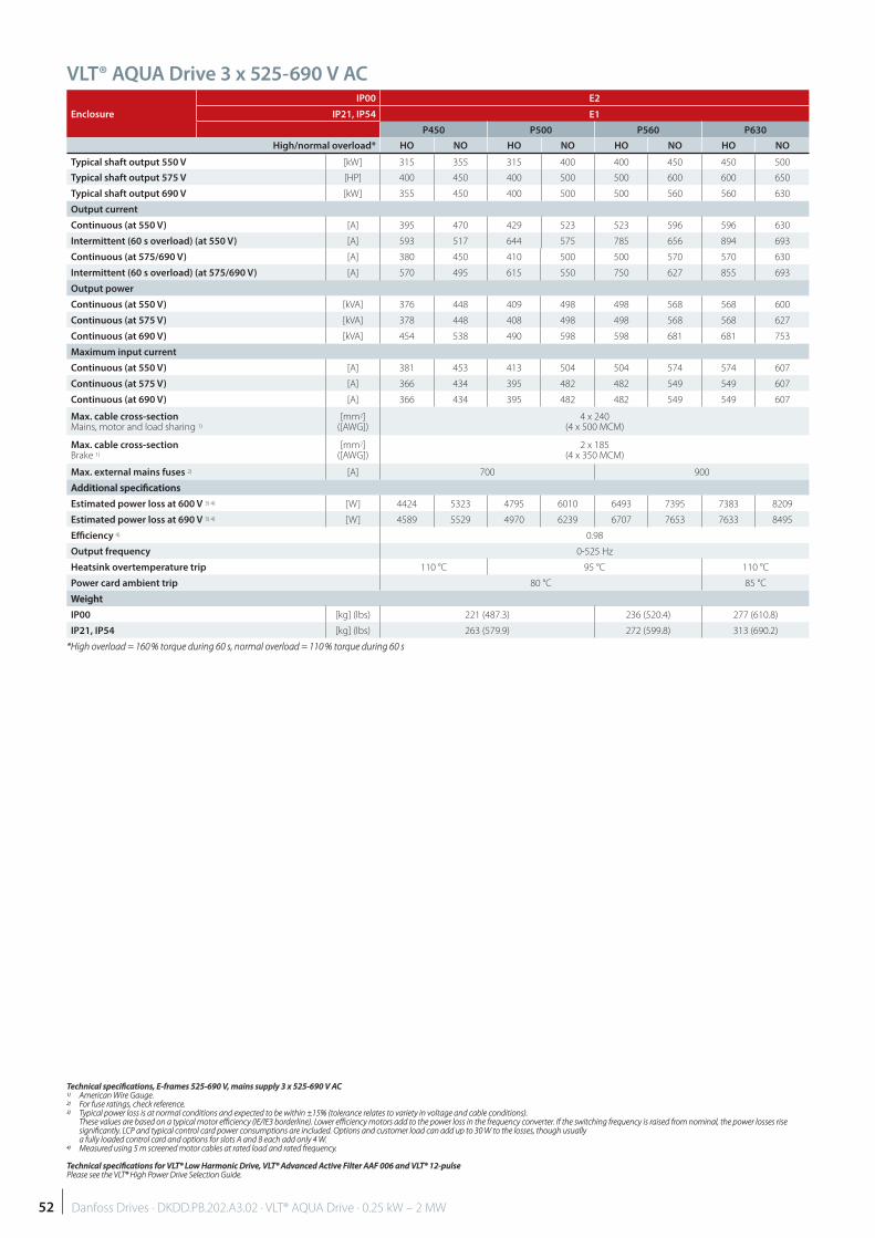
VLT® AQUA Drive 3 x 525-690 V AC
Enclosure
IP00 E2
IP21, IP54 E1
P450 P500 P560 P630
High/normal overload* HO NO HO NO HO NO HO NO
Typical shaft output 550 V [kW] 315 355 315 400 400 450 450 500
Typical shaft output 575 V [HP] 400 450 400 500 500 600 600 650
Typical shaft output 690 V [kW] 355 450 400 500 500 560 560 630
Output current
Continuous (at 550 V) [A] 395 470 429 523 523 596 596 630
Intermittent (60 s overload) (at 550 V) [A] 593 517 644 575 785 656 894 693
Continuous (at 575/690 V) [A] 380 450 410 500 500 570 570 630
Intermittent (60 s overload) (at 575/690 V) [A] 570 495 615 550 750 627 855 693
Output power
Continuous (at 550 V) [kVA] 376 448 409 498 498 568 568 600
Continuous (at 575 V) [kVA] 378 448 408 498 498 568 568 627
Continuous (at 690 V) [kVA] 454 538 490 598 598 681 681 753
Maximum input current
Continuous (at 550 V) [A] 381 453 413 504 504 574 574 607
Continuous (at 575 V) [A] 366 434 395 482 482 549 549 607
Continuous (at 690 V) [A] 366 434 395 482 482 549 549 607
Max. cable cross-section Mains, motor and load sharing 1)
[mm2]([AWG])
4 x 240 (4 x 500 MCM)
Max. cable cross-section Brake 1)
[mm2]([AWG])
2 x 185 (4 x 350 MCM)
Max. external mains fuses 2) [A] 700 900
Additional specifi cationsAdditional specifi cations
Estimated power loss at 600 V 3) 4) [W] 4424 5323 4795 6010 6493 7395 7383 8209
Estimated power loss at 690 V 3) 4) [W] 4589 5529 4970 6239 6707 7653 7633 8495
Effi ciency 4) 0.98
Output frequency 0-525 Hz
Heatsink overtemperature trip 110 °C 95 °C 110 °C
Power card ambient trip 80 °C 85 °C
WeightWeight
IP00 [kg] (lbs) 221 (487.3) 236 (520.4) 277 (610.8)
IP21, IP54 [kg] (lbs) 263 (579.9) 272 (599.8) 313 (690.2)
*High overload = 160 % torque during 60 s, normal overload = 110 % torque during 60 s*High overload = 160 % torque during 60 s, normal overload = 110 % torque during 60 s
Technical specifi cations, E-frames 525-690 V, mains supply 3 x 525-690 V ACTechnical specifi cations, E-frames 525-690 V, mains supply 3 x 525-690 V AC1)1) American Wire Gauge. American Wire Gauge.2)2) For fuse ratings, check reference. For fuse ratings, check reference.3)3) Typical power loss is at normal conditions and expected to be within ±15% (tolerance relates to variety in voltage and cable conditions). Typical power loss is at normal conditions and expected to be within ±15% (tolerance relates to variety in voltage and cable conditions). These values are based on a typical motor effi ciency (IE/IE3 borderline). Lower effi ciency motors add to the power loss in the frequency converter. If the switching frequency is raised from nominal, the power losses rise These values are based on a typical motor effi ciency (IE/IE3 borderline). Lower effi ciency motors add to the power loss in the frequency converter. If the switching frequency is raised from nominal, the power losses rise
signifi cantly. LCP and typical control card power consumptions are included. Options and customer load can add up to 30 W to the losses, though usually signifi cantly. LCP and typical control card power consumptions are included. Options and customer load can add up to 30 W to the losses, though usually a fully loaded control card and options for slots A and B each add only 4 W.a fully loaded control card and options for slots A and B each add only 4 W.
4)4) Measured using 5 m screened motor cables at rated load and rated frequency. Measured using 5 m screened motor cables at rated load and rated frequency.
Technical specifi cations for VLT® Low Harmonic Drive, VLT® Advanced Active Filter AAF 006 and VLT® 12-pulseTechnical specifi cations for VLT® Low Harmonic Drive, VLT® Advanced Active Filter AAF 006 and VLT® 12-pulsePlease see the VLT® High Power Drive Selection Guide.Please see the VLT® High Power Drive Selection Guide.
52 Danfoss Drives · DKDD.PB.202.A3.02 · VLT® AQUA Drive · 0.25 kW – 2 MW
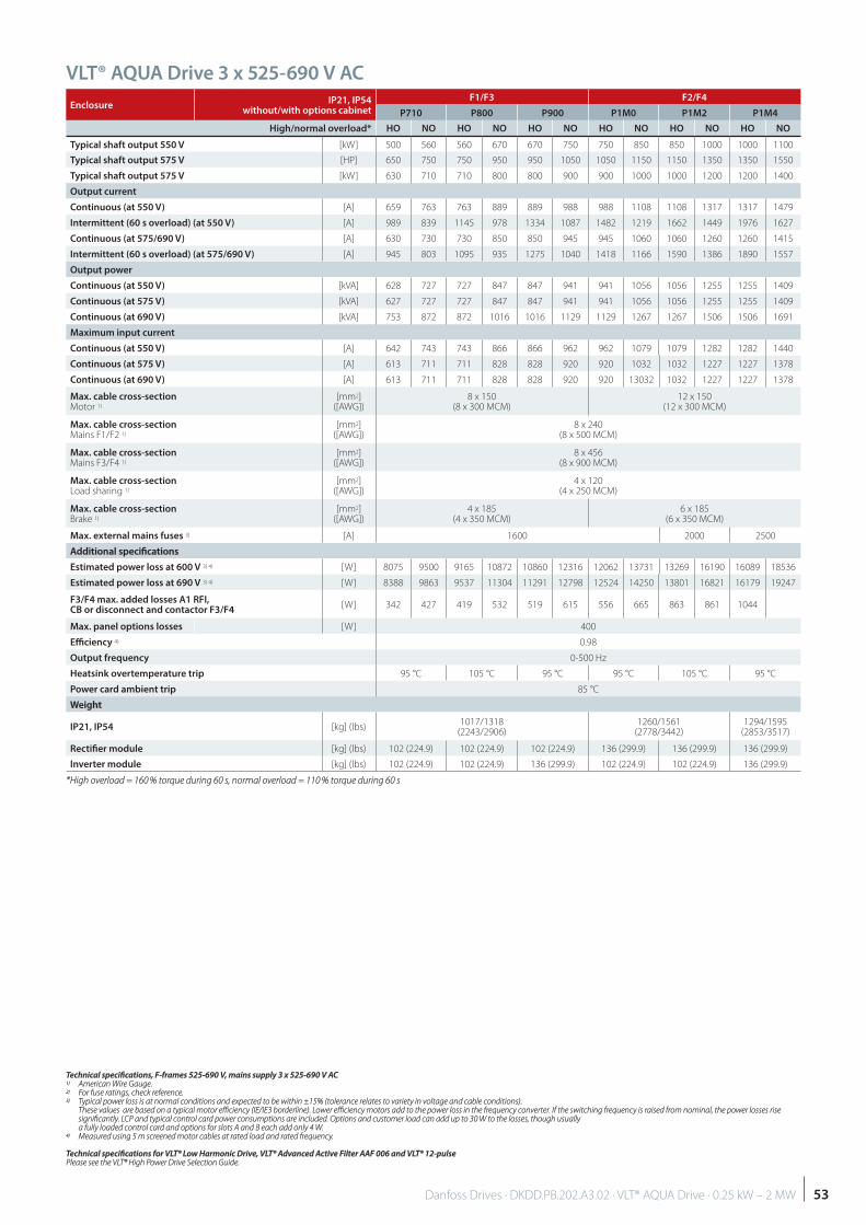
EnclosureIP21, IP54
without/with options cabinet
F1/F3 F2/F4
P710 P800 P900 P1M0 P1M2 P1M4
High/normal overload* HO NO HO NO HO NO HO NO HO NO HO NO
Typical shaft output 550 V [kW] 500 560 560 670 670 750 750 850 850 1000 1000 1100
Typical shaft output 575 V [HP] 650 750 750 950 950 1050 1050 1150 1150 1350 1350 1550
Typical shaft output 575 V [kW] 630 710 710 800 800 900 900 1000 1000 1200 1200 1400
Output current
Continuous (at 550 V) [A] 659 763 763 889 889 988 988 1108 1108 1317 1317 1479
Intermittent (60 s overload) (at 550 V) [A] 989 839 1145 978 1334 1087 1482 1219 1662 1449 1976 1627
Continuous (at 575/690 V) [A] 630 730 730 850 850 945 945 1060 1060 1260 1260 1415
Intermittent (60 s overload) (at 575/690 V) [A] 945 803 1095 935 1275 1040 1418 1166 1590 1386 1890 1557
Output power
Continuous (at 550 V) [kVA] 628 727 727 847 847 941 941 1056 1056 1255 1255 1409
Continuous (at 575 V) [kVA] 627 727 727 847 847 941 941 1056 1056 1255 1255 1409
Continuous (at 690 V) [kVA] 753 872 872 1016 1016 1129 1129 1267 1267 1506 1506 1691
Maximum input current
Continuous (at 550 V) [A] 642 743 743 866 866 962 962 1079 1079 1282 1282 1440
Continuous (at 575 V) [A] 613 711 711 828 828 920 920 1032 1032 1227 1227 1378
Continuous (at 690 V) [A] 613 711 711 828 828 920 920 13032 1032 1227 1227 1378
Max. cable cross-section Motor 1)
[mm2]([AWG])
8 x 150 (8 x 300 MCM)
12 x 150 (12 x 300 MCM)
Max. cable cross-section Mains F1/F2 1)
[mm2]([AWG])
8 x 240 (8 x 500 MCM)
Max. cable cross-section Mains F3/F4 1)
[mm2]([AWG])
8 x 456 (8 x 900 MCM)
Max. cable cross-section Load sharing 1)
[mm2]([AWG])
4 x 120 (4 x 250 MCM)
Max. cable cross-section Brake 1)
[mm2]([AWG])
4 x 185 (4 x 350 MCM)
6 x 185 (6 x 350 MCM)
Max. external mains fuses 3) [A] 1600 2000 2500
Additional specifi cationsAdditional specifi cations
Estimated power loss at 600 V 3) 4) [W] 8075 9500 9165 10872 10860 12316 12062 13731 13269 16190 16089 18536
Estimated power loss at 690 V 3) 4) [W] 8388 9863 9537 11304 11291 12798 12524 14250 13801 16821 16179 19247
F3/F4 max. added losses A1 RFI, CB or disconnect and contactor F3/F4
[W] 342 427 419 532 519 615 556 665 863 861 1044
Max. panel options losses [W] 400
Effi ciency 4) 0.98
Output frequency 0-500 Hz
Heatsink overtemperature trip 95 °C 105 °C 95 °C 95 °C 105 °C 95 °C
Power card ambient trip 85 °C
WeightWeight
IP21, IP54 [kg] (lbs)1017/1318
(2243/2906)1260/1561
(2778/3442)1294/1595
(2853/3517)
Rectifi er module [kg] (lbs) 102 (224.9) 102 (224.9) 102 (224.9) 136 (299.9) 136 (299.9) 136 (299.9)
Inverter module [kg] (lbs) 102 (224.9) 102 (224.9) 136 (299.9) 102 (224.9) 102 (224.9) 136 (299.9)
*High overload = 160 % torque during 60 s, normal overload = 110 % torque during 60 s*High overload = 160 % torque during 60 s, normal overload = 110 % torque during 60 s
VLT® AQUA Drive 3 x 525-690 V AC
Technical specifi cations, F-frames 525-690 V, mains supply 3 x 525-690 V ACTechnical specifi cations, F-frames 525-690 V, mains supply 3 x 525-690 V AC1)1) American Wire Gauge. American Wire Gauge.2)2) For fuse ratings, check reference. For fuse ratings, check reference.3)3) Typical power loss is at normal conditions and expected to be within ±15% (tolerance relates to variety in voltage and cable conditions). Typical power loss is at normal conditions and expected to be within ±15% (tolerance relates to variety in voltage and cable conditions).
These values are based on a typical motor effi ciency (IE/IE3 borderline). Lower effi ciency motors add to the power loss in the frequency converter. If the switching frequency is raised from nominal, the power losses rise These values are based on a typical motor effi ciency (IE/IE3 borderline). Lower effi ciency motors add to the power loss in the frequency converter. If the switching frequency is raised from nominal, the power losses rise signifi cantly. LCP and typical control card power consumptions are included. Options and customer load can add up to 30 W to the losses, though usually signifi cantly. LCP and typical control card power consumptions are included. Options and customer load can add up to 30 W to the losses, though usually a fully loaded control card and options for slots A and B each add only 4 W.a fully loaded control card and options for slots A and B each add only 4 W.
4)4) Measured using 5 m screened motor cables at rated load and rated frequency. Measured using 5 m screened motor cables at rated load and rated frequency.
Technical specifi cations for VLT® Low Harmonic Drive, VLT® Advanced Active Filter AAF 006 and VLT® 12-pulseTechnical specifi cations for VLT® Low Harmonic Drive, VLT® Advanced Active Filter AAF 006 and VLT® 12-pulsePlease see the VLT® High Power Drive Selection Guide.Please see the VLT® High Power Drive Selection Guide.
53Danfoss Drives · DKDD.PB.202.A3.02 · VLT® AQUA Drive · 0.25 kW – 2 MW

VLT® AQUA Drive T2 200 – 240 V T4 380 – 480 V T6 525 – 600 V T7 525 – 690 V
FC 200
kWIP
20
IP2
1
IP5
5
IP6
6
IP0
0
IP2
0
IP2
1
IP5
4
IP5
5
IP6
6
IP2
0
IP2
1
IP5
4
IP5
5
IP6
6
IP0
0
IP2
0
IP2
1
IP5
4
IP5
5
HO NO
PK25 0.25
A2 A2
A4
/A5
A4
/A5
PK37 0.37
A2 A2
A4
/A5
A4
/A5
PK55 0.55
PK75 0.75
A3 A3 A5 A5
P1K1 1.1
A3 A5P1K5 1.5
P2K2 2.2
P3K0 3.0A3 A3 A5 A5
P3K7 3.7
P4K0 4.0 A2 A2 A4/ A5
A3 A3 A5 A5 A3 A5P5K5 3.7 5.5
B3 B1 B1 B1A3 A3 A5 A5
P7K5 5.5 7.5
P11K 7.5 11
B3 B1 B1 B1 B3 B1 B1 B1
B4B2 B2
P15K 11 15B4
B2 B2 B2
P18K 15 18.5
C1 C1 C1P22K 18.5 22C3
B4B2 B2 B2
B4B2 B2 B2
P30K 22 30
P37K 30 37C4 C2 C2 C2
C1 C1 C1 C1 C1 C1
C2 C2
P45K 37 45C3 C3 C3
P55K 45 55
P75K 55 75C4 C2 C2 C2 C4 C2 C2 C2
P90K 75 90
N75K 55 75
D3hD1hD5hD6h
D1hD5hD6h
N90K 75 90
N110 90 110
D3hD1hD5hD6h
D1hD5hD6h
N132 110 132
N160 132 160
N200 160 200
D4hD2hD7hD8h
D2hD7hD8h D4h
D2hD7hD8h
D2hD7hD8h
N250 200 250
N315 250 315
N400 315 400
P315 250 315
P355 315 355
E2 E1 E1P400 355 400
P450 400 450
E2 E1 E1P500 450 500
F1/F3 F1/F3P560 500 560
P630 560 630
P710 630 710
F1/F3 F1/F3P800 710 800F2/F4 F2/F4
P900 800 900
P1M0 900 1000
F2/F4 F2/F4P1M2 1000 1200
P1M4 1200 1400
3 phases
Enclosure overview
54 Danfoss Drives · DKDD.PB.202.A3.02 · VLT® AQUA Drive · 0.25 kW – 2 MW
B1 B2 C1A2 A3 A4 A5 D2h D4h D1h D3hC2
F
D8h D7h D6h D5h
12p
12pE
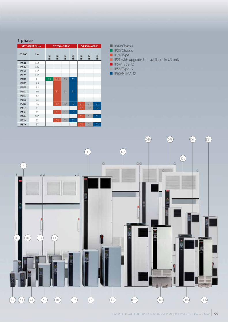
VLT® AQUA Drive S2 200 – 240 V S4 380 – 480 V
FC 200 kW
IP2
0
IP2
1
IP5
5
IP6
6
IP2
1
IP5
5
IP6
6
PK25 0.25
PK37 0.37
PK55 0.55
PK75 0.75
P1K1 1.1 A3 A3 A5 A5
P1K5 1.5
B1 B1 B1
P2K2 2.2
P3K0 3.0
P3K7 3.7
P5K5 5.5
P7K5 7.5 B2 B2 B2 B1 B1 B1
P11K 11 B2 B2 B2
P15K 15 C1 C1 C1
P18K 18.5 C1 C1 C1
P22K 22 C2 C2 C2
P37K 37 C2 C2 C2
■ IP00/Chassis
■ IP20/Chassis
■ IP21/Type 1
■ IP21 with upgrade kit – available in US only
■ IP54/Type 12
■ IP55/Type 12
■ IP66/NEMA 4X
1 phase
B3 B4 C3 C4
55Danfoss Drives · DKDD.PB.202.A3.02 · VLT® AQUA Drive · 0.25 kW – 2 MW
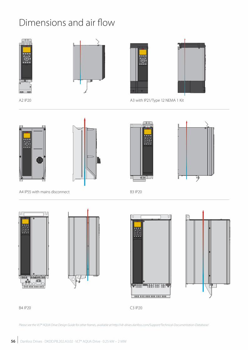
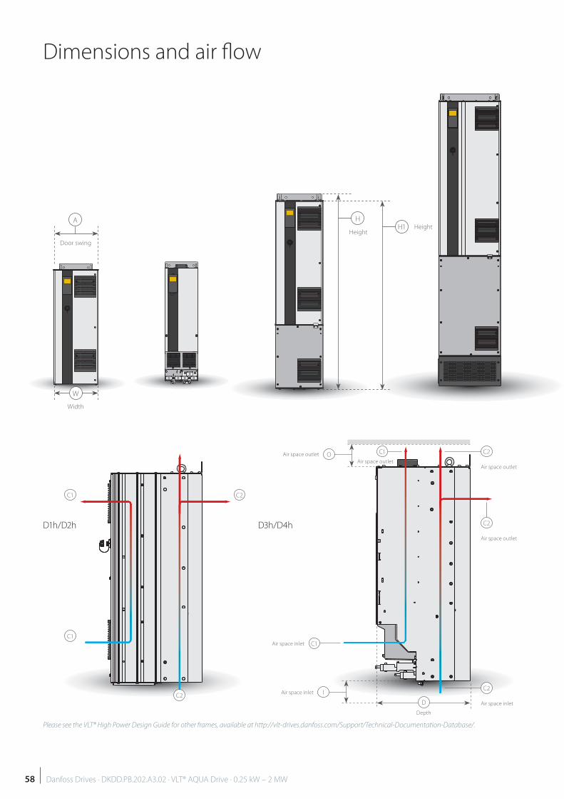
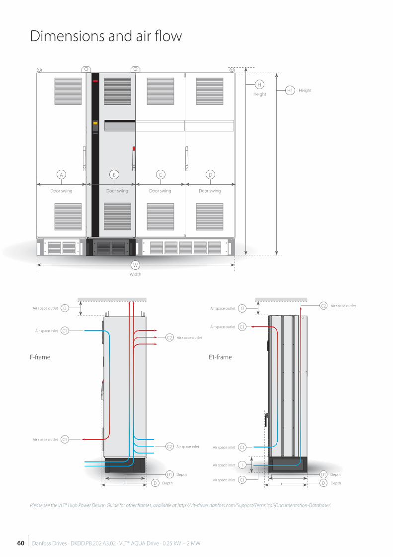
Dimensions and air fl ow
Please see the VLT® AQUA Drive Design Guide for other frames, available at http://vlt-drives.danfoss.com/Support/Technical-Documentation-Database/.
A2 IP20
B3 IP20
C3 IP20
A3 with IP21/Type 12 NEMA 1 Kit
A4 IP55 with mains disconnect
B4 IP20
56 Danfoss Drives · DKDD.PB.202.A3.02 · VLT® AQUA Drive · 0.25 kW – 2 MW
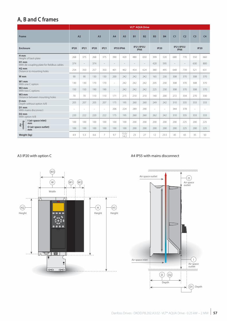
A, B and C framesVLT® AQUA Drive
Frame A2 A3 A4 A5 B1 B2 B3 B4 C1 C2 C3 C4
Enclosure IP20 IP21 IP20 IP21 IP55/IP66IP21/IP55/
IP66IP20
IP21/IP55/IP66
IP20
H mmHeight of back plate
268 375 268 375 390 420 480 650 399 520 680 770 550 660
H1 mm With de-coupling plate for fi eldbus cables
374 – 374 – – – – – 420 595 – – 630 800
H2 mm Distance to mounting holes
254 350 257 350 401 402 454 624 380 495 648 739 521 631
W mm 90 90 130 130 200 242 242 242 165 230 308 370 308 370
W1 mmWith one C option
130 130 170 170 – 242 242 242 205 230 308 370 308 370
W2 mmWith two C options
150 150 190 190 – 242 242 242 225 230 308 370 308 370
W3 mmDistance between mounting holes
70 70 110 110 171 215 210 210 140 200 272 334 270 330
D mmDepth without option A/B 205 207 205 207 175 195 260 260 249 242 310 335 333 333
D1 mmWith mains disconnect
– – – – 206 224 289 290 – – 344 378 – –
D2 mmWith option A/B
220 222 220 222 175 195 260 260 262 242 310 335 333 333
Air
co
oli
ng I (air space inlet)
mm 100 100 100 100 100 100 200 200 200 200 200 225 200 225
O (air space outlet)mm
100 100 100 100 100 100 200 200 200 200 200 225 200 225
Weight (kg) 4.9 5.3 6.6 7 9.713.5/14.2
23 27 12 23.5 45 65 35 50
W
W3
W1 W2
H1HH2
HeightHeightHeight
Width
A3 IP20 with option C A4 IP55 with mains disconnect
O
I
Air space outlet
Air space outlet
D D2
D1
Depth
Depth
Air space outlet
Air space inlet
57Danfoss Drives · DKDD.PB.202.A3.02 · VLT® AQUA Drive · 0.25 kW – 2 MW
W
A
Door swing
Width
Please see the VLT® High Power Design Guide for other frames, available at http://vlt-drives.danfoss.com/Support/Technical-Documentation-Database/.
HH1 Height
Height
D1h/D2h D3h/D4h
OAir space outlet
C1Air space inlet
D
Depth
IAir space inlet
C2C1
C2
C2
Air space outletAir space outlet
Air space inlet
Air space outlet
C2
C2
C1
C1
Dimensions and air fl ow
58 Danfoss Drives · DKDD.PB.202.A3.02 · VLT® AQUA Drive · 0.25 kW – 2 MW
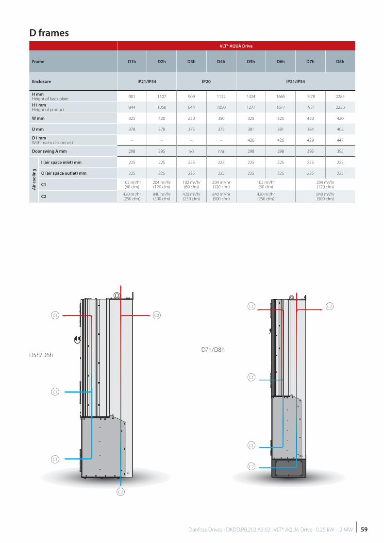
D5h/D6hD7h/D8h
D frames
C1
C1
C2
C2
C2
C1
C1
C1
C1
C2
VLT® AQUA Drive
Frame D1h D2h D3h D4h D5h D6h D7h D8h
Enclosure IP21/IP54 IP20 IP21/IP54
H mmHeight of back plate
901 1107 909 1122 1324 1665 1978 2284
H1 mmHeight of product
844 1050 844 1050 1277 1617 1931 2236
W mm 325 420 250 350 325 325 420 420
D mm 378 378 375 375 381 381 384 402
D1 mmWith mains disconnect
– – – – 426 426 429 447
Door swing A mm 298 395 n/a n/a 298 298 395 395
Air
co
oli
ng
I (air space inlet) mm 225 225 225 225 225 225 225 225
O (air space outlet) mm 225 225 225 225 225 225 225 225
C1102 m3/hr(60 cfm)
204 m3/hr(120 cfm)
102 m3/hr(60 cfm)
204 m3/hr(120 cfm)
102 m3/hr(60 cfm)
204 m3/hr(120 cfm)
C2420 m3/hr(250 cfm)
840 m3/hr(500 cfm)
420 m3/hr(250 cfm)
840 m3/hr(500 cfm)
420 m3/hr(250 cfm)
840 m3/hr(500 cfm)
59Danfoss Drives · DKDD.PB.202.A3.02 · VLT® AQUA Drive · 0.25 kW – 2 MW
Dimensions and air fl ow
HH1
A B C D
HeightHeight
W
Door swing Door swing Door swingDoor swing
Width
D
D1
C2O
C1
Air space outlet
Air space outlet
Air space inlet
Air space inlet
Air space inlet
Air space outlet
Depth
DepthD
D1
C2
C2
C1
C1
OAir space outlet
Air space inlet
Air space outlet
Air space inlet
Depth
Depth
Air space outlet
Please see the VLT® High Power Design Guide for other frames, available at http://vlt-drives.danfoss.com/Support/Technical-Documentation-Database/.
F-frame E1-frame
C1
C1
I
60 Danfoss Drives · DKDD.PB.202.A3.02 · VLT® AQUA Drive · 0.25 kW – 2 MW
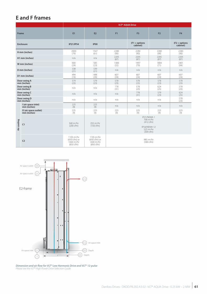
VLT® AQUA Drive
Frame E1 E2 F1 F3 F2 F4
Enclosure IP21/IP54 IP00(F1 + options
cabinet)(F2 + options
cabinet)
H mm (inches)2000(79)
1547(61)
2280(90)
2280(90)
2280(90)
2280(90)
H1 mm (inches) n/a n/a2205(87)
2205(87)
2205(87)
2205(87)
W mm (inches)600(24)
585(23)
1400(55)
1997(79)
1804(71)
2401(94)
D mm (inches)538(21)
539(21)
n/a n/a n/a n/a
D1 mm (inches)494(19)
498(20)
607(24)
607(24)
607(24)
607(24)
Door swing A mm (inches)
579(23)
579(23)
578(23)
578(23)
578(23)
578(23)
Door swing Bmm (inches)
n/a n/a778(31)
578(23)
624(25)
578(23)
Door swing Cmm (inches)
n/a n/a n/a778(31)
579(23)
624(25)
Door swing Dmm (inches)
n/a n/a n/a n/a n/a578(23)
Air
co
oli
ng
I (air space inlet)mm (inches)
225(9)
225(9)
n/a n/a n/a n/a
O (air space outlet)mm (inches)
225(9)
225(9)
225(9)
225(9)
225(9)
225(9)
C1340 m3/hr(200 cfm)
255 m3/hr(150 cfm)
IP21/NEMA 1700 m3/hr(412 cfm)
IP54/NEMA 12525 m3/hr(309 cfm)
C2
1105 m3/hr(650 cfm) or 1444 m3/hr(850 cfm)
1105 m3/hr(650 cfm) or 1444 m3/hr(850 cfm)
985 m3/hr(580 cfm)
E and F frames
D
D1
C2
C2
O
C1
Air space outlet
Air space outlet
Air space inlet
Air space inlet
Depth
Depth
E2-frame
Dimension and air fl ow for VLT® Low Harmonic Drive and VLT® 12-pulsePlease see the VLT® High Power Drive Selection Guide.
I
C1
61Danfoss Drives · DKDD.PB.202.A3.02 · VLT® AQUA Drive · 0.25 kW – 2 MW

A options: FieldbussesAvailable for the full product range
Fieldbus
A
VLT® PROFIBUS DP V1 MCA 101
VLT® DeviceNet MCA 104
VLT® PROFINET MCA 120
VLT® EtherNet/IPMCA 121
VLT® Modbus TCP MCA 122
VLT® PROFIBUS DP MCA 101Operating the frequency converter via a fi eld-bus enables you to reduce the cost of your sys-tem, communicate faster and more effi ciently, and benefi t from an easier user interface.
VLT® PROFIBUS DP MCA 101 provides wide compatibility, a high level of availability, support for all major PLC vendors, and compatibility with future versions
Fast, effi cient communication, transpa-rent installation, advanced diagnosis and parameterisation and auto- confi guration of process data via GSD-fi le
A-cyclic parameterisation using PROFIBUS DP-V1, PROFIdrive or Danfoss FC profi le state machines, PROFIBUS DP-V1, Master Class 1 and 2
Ordering number 130B1100 standard, 130B1200 coated
VLT® DeviceNet MCA 104VLT® DeviceNet MCA 104 off ers robust, effi cient data handling thanks to advanced Producer/Consumer technology.
This modern communications model offers key capabilities that let you effectively determine what information is needed and when
Benefit also from ODVA’s strong conform- ance testing policies, which ensure that products are interoperable
Ordering number 130B1102 standard, 130B1202 coated
The VLT® MCA 121 off ers advanced features as: Built-in high performance switch enabling
line-topology, and eliminating the need for external switches
Advanced switch and diagnoses functions Built-in web server E-mail client for service notification Unicast and Multicast communication
Ordering number 130B1119 standard, 130B1219 coated
VLT® Modbus TCP MCA 122Modbus TCP is the fi rst industrial Ethernet based protocol for automation. The VLT® Mod-bus TCP MCA 122 connects to Modbus TCP based networks. It is able to handle connec-tion interval down to 5 ms in both directions, positioning it among the fastest performing Modbus TCP devices in the market. For master redundancy it features hot swapping between two masters.
Other features: Built-in web-server for remote diagnosis
and reading out basic drive parameters An e-mail notificator can be configured
for sending an e-mail message to one or several receivers, if certain warnings or alarms occurs, or has cleared again
Ordering number 130B1196 standard, 130B1296 coated
VLT® PROFINET MCA 120VLT® PROFINET MCA 120 uniquely combines the highest performance with the highest de-gree of openness. The MCA120 gives the user access to the power of Ethernet. The option is designed so that many of the features from the PROFIBUS MCA 101 can be reused, minimising user eff ort to migrate PROFINET, and securing the investment in PLC program.
Other features: Built-in web server for remote diagnosis and
reading out of basic drive parameters Support of DP-V1 Diagnostic allows easy,
fast and standardized handling of warning and fault information into the PLC, impro-ving bandwidth in the system
PROFINET encompasses a suite of messages and services for a variety of manufacturing automation applications, including control, configuration and information.
Ordering number 130B1135 standard, 130B1235 coated
VLT® EtherNet/IPMCA 121Ethernet is the future standard for communica-tion at the factory fl oor. The VLT® EtherNet/IPMCA 121 is based on the newest technology available for industrial use and handles even the most demanding requirements. EtherNet/IPextends commercial off -the-shelf Ethernet to the Common Industrial Protocol (CIP™) – the same upper-layer protocol and object model found in DeviceNet.
62 Danfoss Drives · DKDD.PB.202.A3.02 · VLT® AQUA Drive · 0.25 kW – 2 MW
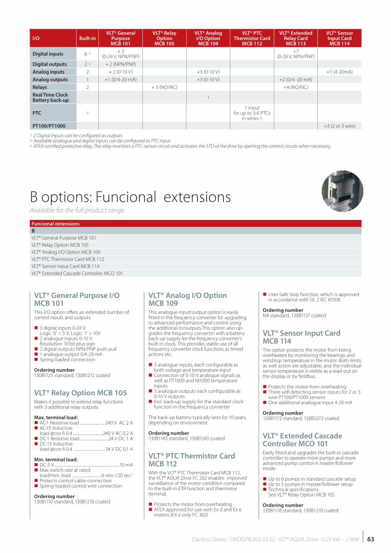
B options: Funcional extensionsAvailable for the full product range
VLT® General Purpose I/O MCB 101This I/O option off ers an extended number of control inputs and outputs:
3 digital inputs 0-24 V: Logic ‘0’ < 5 V; Logic ‘1’ > 10V
2 analogue inputs 0-10 V: Resolution 10 bit plus sign
2 digital outputs NPN/PNP push pull 1 analogue output 0/4-20 mA Spring loaded connection
Ordering number 130B1125 standard, 130B1212 coated
VLT® Relay Option MCB 105Makes it possible to extend relay functions with 3 additional relay outputs.
Max. terminal load: AC-1 Resistive load ........................... 240 V AC 2 A AC-15 Inductive
load @cos fi 0.4 ................................240 V AC 0.2 A DC-1 Resistive load ..............................24 V DC 1 A DC-13 Inductive
load @cos fi 0.4 .................................. 24 V DC 0.1 A
Min. terminal load: DC 5 V .......................................................................10 mA Max switch rate at rated
load/min. load ............................... 6 min-1/20 sec-1
Protects control cable connection Spring-loaded control wire connection
Ordering number 130B1110 standard, 130B1210 coated
VLT® Analog I/O Option MCB 109This analogue input/output option is easily fi tted in the frequency converter for upgrading to advanced performance and control using the additional in/outputs.This option also up-grades the frequency converter with a battery back-up supply for the frequency converter’s built-in clock. This provides stable use of all frequency converter clock functions as timed actions etc.
3 analogue inputs, each configurable as both voltage and temperature input
Connection of 0-10 V analogue signals as well as PT1000 and NI1000 temperature inputs
3 analogue outputs each configurable as 0-10 V outputs
Incl. back-up supply for the standard clock function in the frequency converter
The back-up battery typically lasts for 10 years, depending on environment.
Ordering number130B1143 standard, 130B1243 coated
VLT® PTC Thermistor Card MCB 112With the VLT® PTC Thermistor Card MCB 112, the VLT® AQUA Drive FC 202 enables improved surveillance of the motor condition compared to the built-in ETR function and thermistor terminal.
Protects the motor from overheating ATEX approved for use with Ex d and Ex e motors (EX e only FC 302)
Uses Safe Stop function, which is approved in accordance with SIL 2 IEC 61508
Ordering numberNA standard, 130B1137 coated
VLT® Sensor Input Card MCB 114The option protects the motor from being overheated by monitoring the bearings and windings temperature in the motor. Both limits as well action are adjustable, and the individual sensor temperature is visible as a read-out on the display or by fi eldbus.
Protects the motor from overheating Three self-detecting sensor inputs for 2 or 3
wire PT100/PT1000 sensors One additional analogue input 4-20 mA
Ordering number 130B1172 standard, 130B1272 coated
VLT® Extended Cascade Controller MCO 101Easily fi tted and upgrades the built-in cascade controller to operate more pumps and more advanced pump control in master/follower mode.
Up to 6 pumps in standard cascade setup Up to 5 pumps in master/follower setup Technical specifications:
See VLT® Relay Option MCB 105
Ordering number 130B1118 standard, 130B1218 coated
Funcional extensions
B
VLT® General Purpose MCB 101
VLT® Relay Option MCB 105
VLT® Analog I/O Option MCB 109
VLT® PTC Thermistor Card MCB 112
VLT® Sensor Input Card MCB 114
VLT® Extended Cascade Controller MCO 101
I/O Built-inVLT® General
Purpose MCB 101
VLT® Relay Option
MCB 105
VLT® Analog I/O Option MCB 109
VLT® PTC Thermistor Card
MCB 112
VLT® Extended Relay Card MCB 113
VLT® Sensor Input Card MCB 114
Digital inputs 6 1)+ 3
(0-24 V, NPN/PNP)+7
(0-24 V, NPN/PNP)
Digital outputs 2 1) + 2 (NPN/PNP)
Analog inputs 2 + 2 (0-10 V) +3 (0-10 V) +1 (4-20mA)
Analog outputs 1 +1 (0/4-20 mA) +3 (0-10 V) +2 (0/4 -20 mA)
Relays 2 + 3 (NO/NC) +4 (NO/NC)
Real Time Clock Battery back-up
1
PTC 2)
1 inputfor up to 3-6 PTCs
in series 3)
PT100/PT1000 +3 (2 or 3 wire)
1) 2 Digital Inputs can be confi gured as outputs2) Available analogue and digital inputs can be confi gured as PTC input3) ATEX-certifi ed protective relay. The relay monitors a PTC-sensor circuit and activates the STO of the drive by opening the control circuits when necessary.
63Danfoss Drives · DKDD.PB.202.A3.02 · VLT® AQUA Drive · 0.25 kW – 2 MW
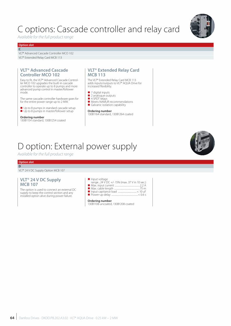
D option: External power supplyAvailable for the full product range
Option slot
D
VLT® 24 V DC Supply Option MCB 107
VLT® 24 V DC Supply MCB 107The option is used to connect an external DC supply to keep the control section and any installed option alive during power failure.
Input voltage range ...24 V DC +/- 15% (max. 37 V in 10 sec.)
Max. input current .............................................. 2.2 A Max. cable length ...............................................75 m Input capitance load .................................. < 10 uF Power-up delay .................................................< 0.6 s
Ordering number 130B1108 uncoated, 130B1208 coated
C options: Cascade controller and relay cardAvailable for the full product range
VLT® Advanced Cascade Controller MCO 102Easy to fi t, the VLT® Advanced Cascade Control-ler MCO 102 upgrades the built-in cascade controller to operate up to 8 pumps and more advanced pump control in master/follower mode.
The same cascade controller hardware goes for for the entire power range up to 2 MW.
Up to 8 pumps in standard cascade setup Up to 8 pumps in master/follower setup
Ordering number 130B1154 standard, 130B1254 coated
VLT® Extended Relay Card MCB 113The VLT® Extended Relay Card MCB 113 adds inputs/outputs to VLT® AQUA Drive for increased fl exibility.
7 digital inputs 2 analogue outputs 4 SPDT relays Meets NAMUR recommendations Galvanic isolation capability
Ordering number 130B1164 standard, 130B1264 coated
Option slot
C
VLT® Advanced Cascade Controller MCO 102
VLT® Extended Relay Card MCB 113
64 Danfoss Drives · DKDD.PB.202.A3.02 · VLT® AQUA Drive · 0.25 kW – 2 MW
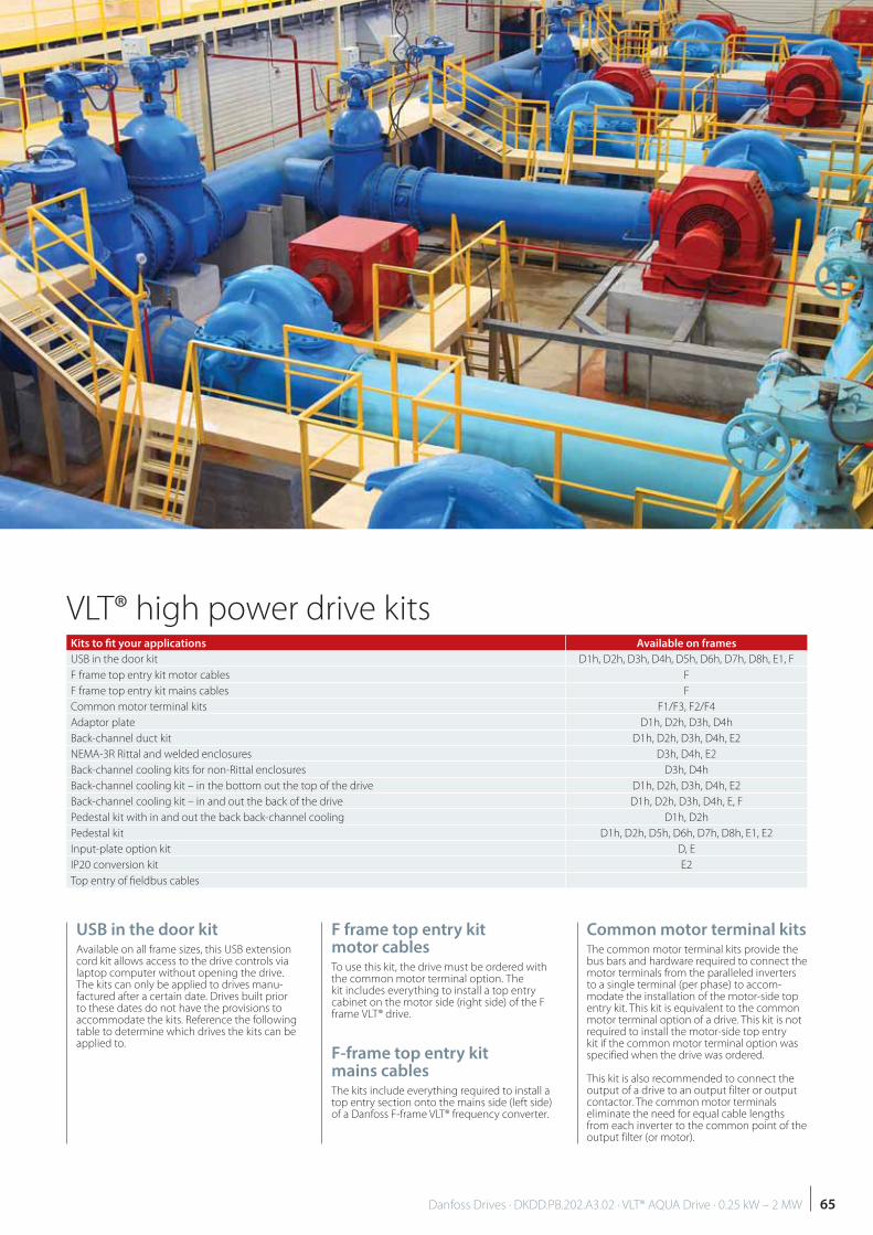
VLT® high power drive kits
USB in the door kitAvailable on all frame sizes, this USB extension cord kit allows access to the drive controls via laptop computer without opening the drive. The kits can only be applied to drives manu-factured after a certain date. Drives built prior to these dates do not have the provisions to accommodate the kits. Reference the following table to determine which drives the kits can be applied to.
Common motor terminal kitsThe common motor terminal kits provide the bus bars and hardware required to connect the motor terminals from the paralleled inverters to a single terminal (per phase) to accom-modate the installation of the motor-side top entry kit. This kit is equivalent to the common motor terminal option of a drive. This kit is not required to install the motor-side top entry kit if the common motor terminal option was specified when the drive was ordered.
This kit is also recommended to connect the output of a drive to an output filter or output contactor. The common motor terminals eliminate the need for equal cable lengths from each inverter to the common point of the output filter (or motor).
F frame top entry kit motor cablesTo use this kit, the drive must be ordered with the common motor terminal option. The kit includes everything to install a top entry cabinet on the motor side (right side) of the F frame VLT® drive.
F-frame top entry kit mains cablesThe kits include everything required to install a top entry section onto the mains side (left side) of a Danfoss F-frame VLT® frequency converter.
Kits to fi t your applications Available on frames
USB in the door kit D1h, D2h, D3h, D4h, D5h, D6h, D7h, D8h, E1, F
F frame top entry kit motor cables F
F frame top entry kit mains cables F
Common motor terminal kits F1/F3, F2/F4
Adaptor plate D1h, D2h, D3h, D4h
Back-channel duct kit D1h, D2h, D3h, D4h, E2
NEMA-3R Rittal and welded enclosures D3h, D4h, E2
Back-channel cooling kits for non-Rittal enclosures D3h, D4h
Back-channel cooling kit – in the bottom out the top of the drive D1h, D2h, D3h, D4h, E2
Back-channel cooling kit – in and out the back of the drive D1h, D2h, D3h, D4h, E, F
Pedestal kit with in and out the back back-channel cooling D1h, D2h
Pedestal kit D1h, D2h, D5h, D6h, D7h, D8h, E1, E2
Input-plate option kit D, E
IP20 conversion kit E2
Top entry of fi eldbus cables
65Danfoss Drives · DKDD.PB.202.A3.02 · VLT® AQUA Drive · 0.25 kW – 2 MW
VLT® high power drive options
Enclosure with 304 stainless steel back-channelFor additional protection from corrosion in harsh environments, units can be ordered in an enclosure that includes a stainless steel back-channel, heavier plated heatsinks and an upgraded fan. This option is recommended in salt-air environ-ments near the ocean.
Mains shieldingLexan® shielding mounted in front of incom-ing power terminals and input plate to protect from accidental contact when the enclosure door is open.
ing includes a power outlet for temporarily powering laptop computers or other devices. Available in two voltages:
230 V, 50 Hz, 2.5 A, CE/ENEC 120 V, 60 Hz, 5 A, UL/cUL
RFI filtersVLT® Series drives feature integrated Class A2 RFI fi lters as standard. If additional levels of RFI/EMC protection are required, they can be obtained using optional Class A1 RFI fi lters, which provide suppression of radio frequency interference and electromagnetic radiation in accordance with EN 55011.
On F-frame drives, the Class A1 RFI fi lter re-quires the addition of the options cabinet. Marine use RFI fi lters are also available.
Space heaters and thermostatMounted on the cabinet interior of D and F frames, space heaters controlled via automatic thermostat prevents condensation inside the enclosure.
The thermostat default settings turn on the heaters at 10°C (50° F) and turn them off at 15.6°C (60° F).
Cabinet light with power outletA light can be mounted on the cabinet interior of F frames to increase visibility during servicing and maintenance. The light hous-
Adaptor plateThe adaptor plate is used to replace an old D-frame drive with the new D-frame drive using the same mounting.
Back-channel duct kitBack-channel duct kits are off ered for conver-sion of the D and E frames. They are off ered in two confi gurations – top and bottom venting and top only venting. Available for the D3h, D4h and E2 frames.
NEMA-3R Rittal and welded enclosuresThe kits are designed to be used with the IP00/IP20/Chassis drives to achieve an enclosure rat-ing of NEMA-3R or NEMA-4. These enclosures are intended for outdoor use to provide a de-gree of protection against inclement weather.
Back-channel cooling kits for non-Rittal enclosuresThe kits are designed to be used with the IP20/Chassis drives in non-Rittal enclosures for in and out the back cooling. Kits do not include plates for mounting in the enclosures
Back-channel cooling kit – in
the bottom and out the back of the driveKit for directing the back-channel air fl ow in the bottom of the drive and out the back.
Back-channel cooling kit – in and out the back of the driveThese kits are designed to be used for redirect-ing the back-channel air fl ow. Factory back-channel cooling directs air in the bottom of the drive and out the top. The kit allows the air to be directed in and out the back of the drive.
Pedestal kit with in and out the back back-channel coolingSee additional documents 177R0508 and 177R0509.
Pedestal kitThe pedestal kit is a 400 mm high pedestal for the D1h and D2h and 200 mm high for the D5h and D6h frames that allow the drives to be fl oor mounted. The front of the pedes-tal has openings for input air to the power components.
Input-plate option kitInput-plate option kits are available for D and E frames. The kits can be ordered to add fuses, disconnect/fuses, RFI, RFI/Fuses, and RFI/Disconnect/Fuses. Please consult the factory for kit ordering numbers.
IP20 conversion kitThis kit is for use with the E2 (IP00) frames. Af-ter installation, the drive will have an enclosure rating of IP20.
Top entry of fieldbus cablesThe top entry kit provides the ability to install fi eldbus cables through the top of the drive. The kit is IP20 when installed. If an increased rating is desired, a diff erent mating connector can be used.
Option type Available on frames
Enclosure with 304 stainless steel back-channel D, E2, F1-F4, F8-F13
Mains shielding D1h, D2h, D5h, D6h, D7h, D8h, E1
Space heaters and thermostat D1h, D2h, D5h, D6h, D7h, D8h, F
Cabinet light with power outlet F
RFI fi lters D, E, F3, F4
Residual Current Device (RCD) F
Insulation Resistance Monitor (IRM) F3, F4
Safe Stop with Pilz Safety Relay F
Emergency Stop with Pilz Safety Relay F1-F4
Brake Chopper (IGBTs) D, E, F
Regeneration terminals D3h, D4h, E, F
Loadsharing terminals D, E, F
Disconnect D5h, D7h, E, F3, F4
Circuit breakers D6h, D8h, F
Contactors D6h, D8h, F3, F4
Manual motor starters F
30 Amp, fuse-protected terminals F
24 VDC power supply F
External temperature monitoring F
66 Danfoss Drives · DKDD.PB.202.A3.02 · VLT® AQUA Drive · 0.25 kW – 2 MW

Residual Current Device (RCD)Uses the core balance method to moni-tor ground fault currents in grounded and high-resistance grounded systems (TN and TT systems in IEC terminology). There is a pre-warning (50% of main alarm set-point) and a main alarm set-point. Associated with each setpoint is an SPDT alarm relay for external use. Requires an external “window-type” cur-rent transformer(supplied and installed by customer).
Integrated into the drive’s safe-stop circuit IEC 60755 Type B device monitors, pulsed
DC, and pure DC ground fault currents LED bar graph indicator of the ground fault
current level from 10-100% of the setpoint Fault memory TEST / RESET button
Insulation Resistance Monitor (IRM)Monitors the insulation resistance in un-grounded systems (IT systems in IEC terminol-ogy) between the system phase conductors and ground. There is an ohmic pre-warning and a main alarm setpoint for the insulation level. Associated with each setpoint is an SPDT alarm relay for external use. Note: only one in-sulation resistance monitor can be connected to each ungrounded (IT) system.
Integrated into the drive’s safe-stop circuit LCD display of insulation resistance Fault memory INFO, TEST, and RESET buttons
Safe Stop with Pilz Safety RelayAvailable on F frame. Enables the Pilz Relay to fit in the F frames without requiring an option cabinet. The Relay is used in the external tem-perature monitoring option. If PTC monitoring is required, the MCB 112 PTC thermistor option must be ordered.
Emergency Stop with Pilz Safety RelayIncludes a redundant 4-wire emergency-stop pushbutton mounted on the front of the enclosure and a Pilz relay that monitors it in conjunction with the drive’s safe-stop circuit and contactor position. Requires a contactor and the F frame options cabinet.
Brake Chopper (IGBTs)Brake terminals with an IGBT brake chopper circuit allow for the connection of external brake resistors. For detailed data on brake resistors.
Regeneration terminalsAllow connection of regeneration units to the DC bus on the capacitor bank side of the DC-link reactors for regenerative braking. The F-frame regeneration terminals are sized for approximately ½ the power rating of the drive. Consult the factory for regeneration power limits based on the specific drive size and voltage.
24 VDC power supply 5 Amp, 120 W, 24 VDC Protected against output overcurrent, over-
load, short circuits, and overtemperature For powering customer-supplied accessory
devices such as sensors, PLC I/O, contactors, temperature probes, indicator lights, and/or other electronic hardware
Diagnostics include a dry DC-ok contact, a green DC-ok LED, and a red overload LED
External temperature monitoringDesigned for monitoring temperatures of external system components, such as the mo-tor windings and/or bearings. Includes eight universal input modules plus two dedicated thermistor input modules. All ten modules are integrated into the drive’s safe-stop circuit and can be monitored via a fi eldbus network (requires the purchase of a separate module/bus coupler). A Safe Stop brake option must be ordered to choose External temperature monitoring.
Universal inputs (5)Signal types: RTD inputs (including Pt100), 3-wire or
4-wire Thermocouple Analogue current or analog voltage
Additional features: One universal output, configurable for
analog voltage or analogue current Two output relays (N.O.) Dual-line LC display and LED diagnostics Sensor lead wire break, short-circuit, and
incorrect polarity detection Interface setup software If 3 PTC are required, MCB112 control card
option must be added.
Additional external temperature monitors: This option is provided in case you need
more than the MCB114 and MCB 112 provi-des.
Loadsharing terminalsThese terminals connect to the DC-bus on the rectifier side of the DC-link reactor and allow for the sharing of DC bus power between multiple drives. The F-frame loadsharing terminals are sized for approximately 1/3 the power rating of the drive. Consult the factory for loadsharing limits based on the specific drive size and voltage.
DisconnectA door-mounted handle allows for the manual operation of a power disconnect switch to enable and disable power to the drive, increas-ing safety during servicing. The disconnect is interlocked with the cabinet doors to prevent them from being opened while power is still applied.
Circuit breakersA circuit breaker can be remotely tripped but must be manually reset. Circuit breakers are interlocked with the cabinet doors to prevent them from being opened while power is still applied. When a circuit breaker is ordered as an option, fuses are also included for fast-acting current overload protection of the variable frequency drive.
ContactorsAn electrically controlled contactor switch al-lows for the remote enabling and disabling of power to the drive. An auxiliary contact on the contactor is monitored by the Pilz Safety if the IEC Emergency Stop option is ordered.
Manual motor startersProvide 3-phase power for electric cooling blowers often required for larger motors. Power for the starters is provided from the load side of any supplied contactor, circuit breaker, or disconnect switch and from the input side of the Class 1 RFI fi lter (if an RFI fi lter option is ordered). Power is fused before each motor starter, and is off when the incoming power to the drive is off . Up to two starters are allowed (one if a 30-amp, fuse-protected circuit is ordered). Integrated into the drive’s safe-stop circuit.
Unit features include: Operation switch (on/off) Short-circuit and overload protection with
test function Manual reset function
30 Amp, fuse-protected terminals 3-phase power matching incoming mains
voltage for powering auxiliary customer equipment
Not available if two manual motor starters are selected
Terminals are off when the incoming power to the drive is off
Power for the fused protected terminals will be provided from the load side of any sup-plied contactor, circuit breaker, or discon-nect switch and from the input side of the Class 1 RFI filter (if a RFI filter is ordered as an option).
67Danfoss Drives · DKDD.PB.202.A3.02 · VLT® AQUA Drive · 0.25 kW – 2 MW
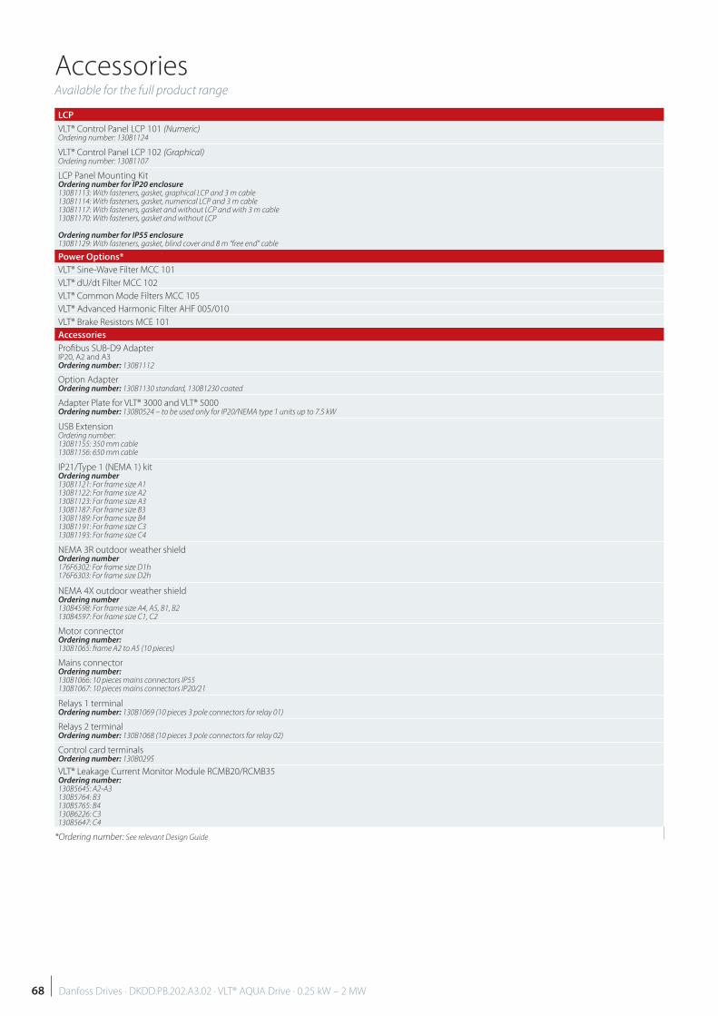
AccessoriesAvailable for the full product range
LCP
VLT® Control Panel LCP 101 (Numeric)Ordering number: 130B1124
VLT® Control Panel LCP 102 (Graphical)Ordering number: 130B1107
LCP Panel Mounting KitOrdering number for IP20 enclosure130B1113: With fasteners, gasket, graphical LCP and 3 m cable130B1114: With fasteners, gasket, numerical LCP and 3 m cable130B1117: With fasteners, gasket and without LCP and with 3 m cable130B1170: With fasteners, gasket and without LCP
Ordering number for IP55 enclosure130B1129: With fasteners, gasket, blind cover and 8 m “free end” cable
Power Options*
VLT® Sine-Wave Filter MCC 101
VLT® dU/dt Filter MCC 102
VLT® Common Mode Filters MCC 105
VLT® Advanced Harmonic Filter AHF 005/010
VLT® Brake Resistors MCE 101
Accessories
Profi bus SUB-D9 AdapterIP20, A2 and A3 Ordering number: 130B1112
Option AdapterOrdering number: 130B1130 standard, 130B1230 coated
Adapter Plate for VLT® 3000 and VLT® 5000Ordering number: 130B0524 – to be used only for IP20/NEMA type 1 units up to 7.5 kW
USB ExtensionOrdering number: 130B1155: 350 mm cable130B1156: 650 mm cable
IP21/Type 1 (NEMA 1) kitOrdering number130B1121: For frame size A1130B1122: For frame size A2130B1123: For frame size A3130B1187: For frame size B3130B1189: For frame size B4130B1191: For frame size C3130B1193: For frame size C4
NEMA 3R outdoor weather shieldOrdering number176F6302: For frame size D1h176F6303: For frame size D2h
NEMA 4X outdoor weather shieldOrdering number130B4598: For frame size A4, A5, B1, B2130B4597: For frame size C1, C2
Motor connectorOrdering number: 130B1065: frame A2 to A5 (10 pieces)
Mains connectorOrdering number: 130B1066: 10 pieces mains connectors IP55130B1067: 10 pieces mains connectors IP20/21
Relays 1 terminalOrdering number: 130B1069 (10 pieces 3 pole connectors for relay 01)
Relays 2 terminalOrdering number: 130B1068 (10 pieces 3 pole connectors for relay 02)
Control card terminalsOrdering number: 130B0295
VLT® Leakage Current Monitor Module RCMB20/RCMB35Ordering number:130B5645: A2-A3 130B5764: B3 130B5765: B4130B6226: C3130B5647: C4
*Ordering number: See relevant Design Guide
68 Danfoss Drives · DKDD.PB.202.A3.02 · VLT® AQUA Drive · 0.25 kW – 2 MW
69
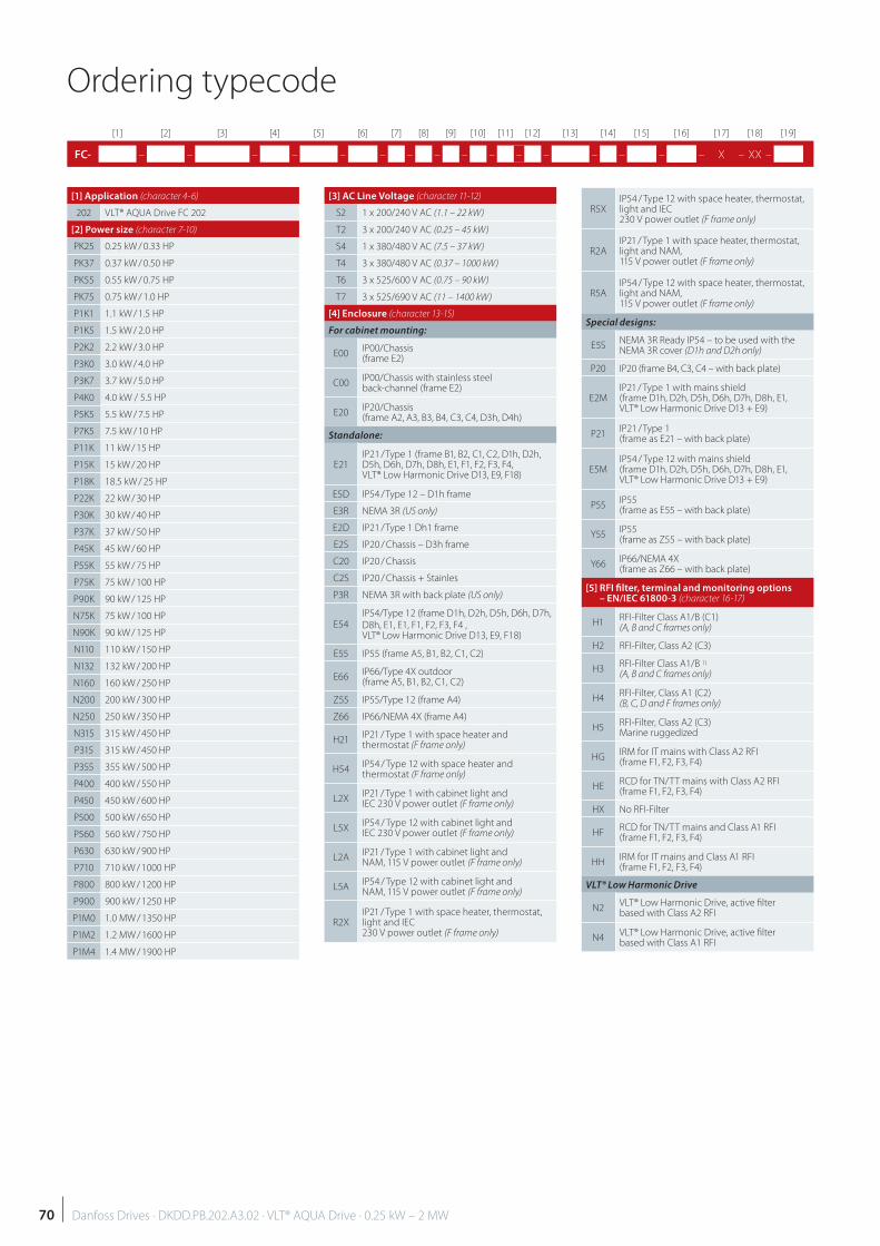
Ordering typecode
[1] [2] [3] [4] [5] [6] [7] [8] [9] [10] [11] [12] [13] [14] [15] [16] [17] [18] [19]
FC- – – – – – – – – – – – – – – – CX – X – XX –
[1] Application (character 4-6)
202 VLT® AQUA Drive FC 202
[2] Power size (character 7-10)
PK25 0.25 kW / 0.33 HP
PK37 0.37 kW / 0.50 HP
PK55 0.55 kW / 0.75 HP
PK75 0.75 kW / 1.0 HP
P1K1 1.1 kW / 1.5 HP
P1K5 1.5 kW / 2.0 HP
P2K2 2.2 kW / 3.0 HP
P3K0 3.0 kW / 4.0 HP
P3K7 3.7 kW / 5.0 HP
P4K0 4.0 kW / 5.5 HP
P5K5 5.5 kW / 7.5 HP
P7K5 7.5 kW / 10 HP
P11K 11 kW / 15 HP
P15K 15 kW / 20 HP
P18K 18.5 kW / 25 HP
P22K 22 kW / 30 HP
P30K 30 kW / 40 HP
P37K 37 kW / 50 HP
P45K 45 kW / 60 HP
P55K 55 kW / 75 HP
P75K 75 kW / 100 HP
P90K 90 kW / 125 HP
N75K 75 kW / 100 HP
N90K 90 kW / 125 HP
N110 110 kW / 150 HP
N132 132 kW / 200 HP
N160 160 kW / 250 HP
N200 200 kW / 300 HP
N250 250 kW / 350 HP
N315 315 kW / 450 HP
P315 315 kW / 450 HP
P355 355 kW / 500 HP
P400 400 kW / 550 HP
P450 450 kW / 600 HP
P500 500 kW / 650 HP
P560 560 kW / 750 HP
P630 630 kW / 900 HP
P710 710 kW / 1000 HP
P800 800 kW / 1200 HP
P900 900 kW / 1250 HP
P1M0 1.0 MW / 1350 HP
P1M2 1.2 MW / 1600 HP
P1M4 1.4 MW / 1900 HP
[3] AC Line Voltage (character 11-12)
S2 1 x 200/240 V AC (1.1 – 22 kW)
T2 3 x 200/240 V AC (0.25 – 45 kW)
S4 1 x 380/480 V AC (7.5 – 37 kW)
T4 3 x 380/480 V AC (0.37 – 1000 kW)
T6 3 x 525/600 V AC (0.75 – 90 kW)
T7 3 x 525/690 V AC (11 – 1400 kW)
[4] Enclosure (character 13-15)
For cabinet mounting:
E00IP00/Chassis (frame E2)
C00IP00/Chassis with stainless steel back-channel (frame E2)
E20IP20/Chassis (frame A2, A3, B3, B4, C3, C4, D3h, D4h)
Standalone:
E21IP21 / Type 1 (frame B1, B2, C1, C2, D1h, D2h, D5h, D6h, D7h, D8h, E1, F1, F2, F3, F4,VLT® Low Harmonic Drive D13, E9, F18)
E5D IP54 / Type 12 – D1h frame
E3R NEMA 3R (US only)
E2D IP21 / Type 1 Dh1 frame
E2S IP20 / Chassis – D3h frame
C20 IP20 / Chassis
C2S IP20 / Chassis + Stainles
P3R NEMA 3R with back plate (US only)
E54IP54/Type 12 (frame D1h, D2h, D5h, D6h, D7h, D8h, E1, E1, F1, F2, F3, F4 , VLT® Low Harmonic Drive D13, E9, F18)
E55 IP55 (frame A5, B1, B2, C1, C2)
E66IP66/Type 4X outdoor (frame A5, B1, B2, C1, C2)
Z55 IP55/Type 12 (frame A4)
Z66 IP66/NEMA 4X (frame A4)
H21IP21 / Type 1 with space heater and thermostat (F frame only)
H54IP54 / Type 12 with space heater and thermostat (F frame only)
L2XIP21 / Type 1 with cabinet light and IEC 230 V power outlet (F frame only)
L5XIP54 / Type 12 with cabinet light and IEC 230 V power outlet (F frame only)
L2AIP21 / Type 1 with cabinet light and NAM, 115 V power outlet (F frame only)
L5AIP54 / Type 12 with cabinet light and NAM, 115 V power outlet (F frame only)
R2XIP21 / Type 1 with space heater, thermostat, light and IEC 230 V power outlet (F frame only)
R5XIP54 / Type 12 with space heater, thermostat, light and IEC 230 V power outlet (F frame only)
R2AIP21 / Type 1 with space heater, thermostat, light and NAM, 115 V power outlet (F frame only)
R5AIP54 / Type 12 with space heater, thermostat, light and NAM, 115 V power outlet (F frame only)
Special designs:
E5SNEMA 3R Ready IP54 – to be used with the NEMA 3R cover (D1h and D2h only)
P20 IP20 (frame B4, C3, C4 – with back plate)
E2MIP21 / Type 1 with mains shield (frame D1h, D2h, D5h, D6h, D7h, D8h, E1, VLT® Low Harmonic Drive D13 + E9)
P21IP21 / Type 1 (frame as E21 – with back plate)
E5MIP54 / Type 12 with mains shield (frame D1h, D2h, D5h, D6h, D7h, D8h, E1, VLT® Low Harmonic Drive D13 + E9)
P55IP55 (frame as E55 – with back plate)
Y55IP55 (frame as Z55 – with back plate)
Y66IP66/NEMA 4X (frame as Z66 – with back plate)
[5] RFI fi lter, terminal and monitoring options – EN/IEC 61800-3 (character 16-17)
H1RFI-Filter Class A1/B (C1)(A, B and C frames only)
H2 RFI-Filter, Class A2 (C3)
H3RFI-Filter Class A1/B 1)
(A, B and C frames only)
H4RFI-Filter, Class A1 (C2)(B, C, D and F frames only)
H5RFI-Filter, Class A2 (C3)Marine ruggedized
HGIRM for IT mains with Class A2 RFI(frame F1, F2, F3, F4)
HERCD for TN/TT mains with Class A2 RFI(frame F1, F2, F3, F4)
HX No RFI-Filter
HFRCD for TN/TT mains and Class A1 RFI(frame F1, F2, F3, F4)
HHIRM for IT mains and Class A1 RFI(frame F1, F2, F3, F4)
VLT® Low Harmonic Drive
N2VLT® Low Harmonic Drive, active fi lter based with Class A2 RFI
N4VLT® Low Harmonic Drive, active fi lter based with Class A1 RFI
70 Danfoss Drives · DKDD.PB.202.A3.02 · VLT® AQUA Drive · 0.25 kW – 2 MW
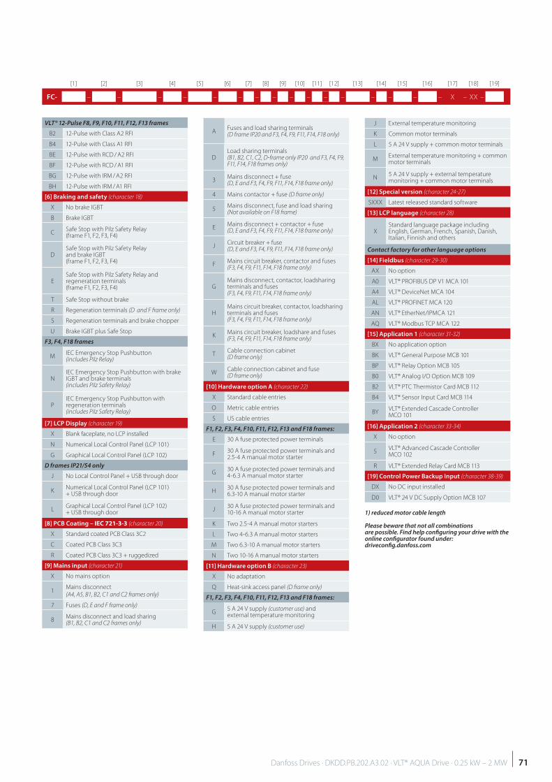
[1] [2] [3] [4] [5] [6] [7] [8] [9] [10] [11] [12] [13] [14] [15] [16] [17] [18] [19]
FC- – – – – – – – – – – – – – – – CX – X – XX –
VLT® 12-Pulse F8, F9, F10, F11, F12, F13 frames
B2 12-Pulse with Class A2 RFI
B4 12-Pulse with Class A1 RFI
BE 12-Pulse with RCD / A2 RFI
BF 12-Pulse with RCD / A1 RFI
BG 12-Pulse with IRM / A2 RFI
BH 12-Pulse with IRM / A1 RFI
[6] Braking and safety (character 18)
X No brake IGBT
B Brake IGBT
CSafe Stop with Pilz Safety Relay (frame F1, F2, F3, F4)
DSafe Stop with Pilz Safety Relay and brake IGBT (frame F1, F2, F3, F4)
ESafe Stop with Pilz Safety Relay and regeneration terminals (frame F1, F2, F3, F4)
T Safe Stop without brake
R Regeneration terminals (D and F frame only)
S Regeneration terminals and brake chopper
U Brake IGBT plus Safe Stop
F3, F4, F18 frames
MIEC Emergency Stop Pushbutton (includes Pilz Relay)
NIEC Emergency Stop Pushbutton with brake IGBT and brake terminals (includes Pilz Safety Relay)
PIEC Emergency Stop Pushbutton with regeneration terminals (includes Pilz Safety Relay)
[7] LCP Display (character 19)
X Blank faceplate, no LCP installed
N Numerical Local Control Panel (LCP 101)
G Graphical Local Control Panel (LCP 102)
D frames IP21/54 only
J No Local Control Panel + USB through door
KNumerical Local Control Panel (LCP 101) + USB through door
LGraphical Local Control Panel (LCP 102) + USB through door
[8] PCB Coating – IEC 721-3-3 (character 20)
X Standard coated PCB Class 3C2
C Coated PCB Class 3C3
R Coated PCB Class 3C3 + ruggedized
[9] Mains input (character 21)
X No mains option
1Mains disconnect (A4, A5, B1, B2, C1 and C2 frames only)
7 Fuses (D, E and F frame only)
8Mains disconnect and load sharing(B1, B2, C1 and C2 frames only)
AFuses and load sharing terminals (D frame IP20 and F3, F4, F9, F11, F14, F18 only)
DLoad sharing terminals(B1, B2, C1, C2, D-frame only IP20 and F3, F4, F9, F11, F14, F18 frames only)
3Mains disconnect + fuse (D, E and F3, F4, F9, F11, F14, F18 frame only)
4 Mains contactor + fuse (D frame only)
5Mains disconnect, fuse and load sharing(Not available on F18 frame)
EMains disconnect + contactor + fuse(D, E and F3, F4, F9, F11, F14, F18 frame only)
JCircuit breaker + fuse(D, E and F3, F4, F9, F11, F14, F18 frame only)
FMains circuit breaker, contactor and fuses(F3, F4, F9, F11, F14, F18 frame only)
GMains disconnect, contactor, loadsharing terminals and fuses(F3, F4, F9, F11, F14, F18 frame only)
HMains circuit breaker, contactor, loadsharing terminals and fuses(F3, F4, F9, F11, F14, F18 frame only)
KMains circuit breaker, loadshare and fuses(F3, F4, F9, F11, F14, F18 frame only)
TCable connection cabinet (D frame only)
WCable connection cabinet and fuse (D frame only)
[10] Hardware option A (character 22)
X Standard cable entries
O Metric cable entries
S US cable entries
F1, F2, F3, F4, F10, F11, F12, F13 and F18 frames:
E 30 A fuse protected power terminals
F30 A fuse protected power terminals and 2.5-4 A manual motor starter
G30 A fuse protected power terminals and 4-6.3 A manual motor starter
H30 A fuse protected power terminals and 6.3-10 A manual motor starter
J30 A fuse protected power terminals and 10-16 A manual motor starter
K Two 2.5-4 A manual motor starters
L Two 4-6.3 A manual motor starters
M Two 6.3-10 A manual motor starters
N Two 10-16 A manual motor starters
[11] Hardware option B (character 23)
X No adaptation
Q Heat-sink access panel (D frame only)
F1, F2, F3, F4, F10, F11, F12, F13 and F18 frames:
G5 A 24 V supply (customer use) and external temperature monitoring
H 5 A 24 V supply (customer use)
J External temperature monitoring
K Common motor terminals
L 5 A 24 V supply + common motor terminals
MExternal temperature monitoring + common motor terminals
N5 A 24 V supply + external temperature monitoring + common motor terminals
[12] Special version (character 24-27)
SXXX Latest released standard software
[13] LCP language (character 28)
XStandard language package including English, German, French, Spanish, Danish, Italian, Finnish and others
Contact factory for other language options
[14] Fieldbus (character 29-30)
AX No option
A0 VLT® PROFIBUS DP V1 MCA 101
A4 VLT® DeviceNet MCA 104
AL VLT® PROFINET MCA 120
AN VLT® EtherNet/IPMCA 121
AQ VLT® Modbus TCP MCA 122
[15] Application 1 (character 31-32)
BX No application option
BK VLT® General Purpose MCB 101
BP VLT® Relay Option MCB 105
B0 VLT® Analog I/O Option MCB 109
B2 VLT® PTC Thermistor Card MCB 112
B4 VLT® Sensor Input Card MCB 114
BYVLT® Extended Cascade Controller MCO 101
[16] Application 2 (character 33-34)
X No option
5VLT® Advanced Cascade Controller MCO 102
R VLT® Extended Relay Card MCB 113
[19] Control Power Backup Input (character 38-39)
DX No DC input installed
D0 VLT® 24 V DC Supply Option MCB 107
1) reduced motor cable length
Please beware that not all combinations are possible. Find help confi guring your drive with the online confi gurator found under: driveconfi g.danfoss.com
71Danfoss Drives · DKDD.PB.202.A3.02 · VLT® AQUA Drive · 0.25 kW – 2 MW

In a competitive worldnothing beats know how and experienceDanfoss has produced more than 10
million drives over the last 45 years.
We are now among the world’s top
three low voltage drive producers
and are the world’s largest dedicated
drive provider. We’re a solid company
you can trust to deliver. As the fi rst
company to ever produce a dedicated
VLT® AQUA Drive, we have a wealth
of know how and experience to share
with our customers in the demanding
water and wastewater segments.
Freedom of choiceOur philosophy has always been to be
motor independent, so you are free
to select not only the best drive, but
also the best motor on the market. This
philosophy has recently resulted in
the major benefi ts of our unique VVC+
technology for high speed PM motor
applications, which are increasingly
being used to maximize blower
effi ciency.
Quality for a longer lifeQuality has always been a corner
stone for Danfoss. With AQUA Drives
the design rule has always been to
only load components to 80% of their
maximum tolerance. Combine this
with a unique cooling system which
reduces dust and contamination by a
factor of 10, and you get a drive that
off ers you extremely high reliability and
a longer life.
Factory tested for reliabilityBecause our reputation is based on
reliability, we test our drives like no-
one else: Each single VLT® AQUA Drive
is connected to a motor and real-life
tested 100 %, so you can be confi dent
that it will work on commission.
Local backup – globallyVLT® motor controllers operate
in applications all over the world and
Danfoss Drives’ experts located in
more than 100 countries are ready to
support you with application advice
and service wherever you may be.
Danfoss Drives’ experts won’t stop until
your drive challenges are solved.
The Danfoss water world
Danfoss Drives, Ulsnaes 1, DK-6300 Graasten, Denmark, Tel. +45 74 88 22 22, Fax +45 74 65 25 80, www.vlt-drives.danfoss.com, E-mail: [email protected]
DKDD.PB.202.A3.02 © Copyright Danfoss Drives PE-MSMBM | 2015.09