Programming Guide VLT PROFIBUS DP MCA 101 - Главная · PDF fileMAKING MODERN LIVING...
60
MAKING MODERN LIVING POSSIBLE Programming Guide VLT ® PROFIBUS DP MCA 101 VLT ® Frequency Converter Series FC 102 • FC 103 • FC 202 • FC 301/302 • FCD 302 www.danfoss.com/drives
Transcript of Programming Guide VLT PROFIBUS DP MCA 101 - Главная · PDF fileMAKING MODERN LIVING...

MAKING MODERN LIVING POSSIBLE
Programming GuideVLT® PROFIBUS DP MCA 101VLT® Frequency Converter Series FC 102 • FC 103 • FC 202 • FC301/302 • FCD 302
www.danfoss.com/drives


Contents
1 Introduction 3
1.1 Purpose of the Manual 3
1.2 Additional Resources 3
1.3 Document and Software Version 3
1.4 Product Overview 3
1.5 Approvals and Certifications 4
1.6 Symbols, Abbreviations and Conventions 5
2 Safety 6
2.1 Safety Symbols 6
2.2 Qualified Personnel 6
2.3 Safety Precautions 6
3 Configuration 8
3.1 Configure the PROFIBUS Network 8
3.2 Configure the Master 9
3.2.1 GSD File 9
3.3 Configure the Frequency Converter 11
3.3.1 Frequency Converter Parameters 11
3.3.2 LEDs 11
4 Control 13
4.1 PPO Types 13
4.2 Process Data 14
4.2.1 Process Control Data 14
4.2.2 Process Status Data 14
4.2.3 Reference Handling 15
4.2.4 Process Control Operation 15
4.2.5 Influence of the Digital Input Terminals upon FC Control Mode 16
4.3 Control Profile 16
4.4 PROFIdrive Control Profile 16
4.4.1 Control Word according to PROFIdrive Profile (CTW) 16
4.4.2 Status Word according to PROFIdrive Profile (STW) 18
4.4.3 PROFIdrive State Transition Diagram 19
4.5 Danfoss FC Control Profile 20
4.5.1 Control Word according to FC Profile (CTW) 20
4.5.2 Status Word according to FC Profile (STW) 21
4.6 Synchronise and Freeze 22
4.6.1 SYNC/UNSYNC 22
4.6.2 FREEZE/UNFREEZE 22
Contents Programming Guide
MG37G102 Danfoss A/S © Rev. 05/2014 All rights reserved. 1
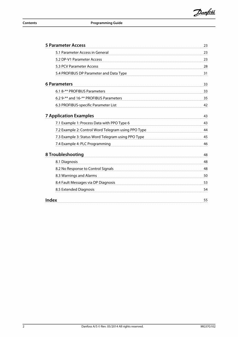
5 Parameter Access 23
5.1 Parameter Access in General 23
5.2 DP-V1 Parameter Access 23
5.3 PCV Parameter Access 28
5.4 PROFIBUS DP Parameter and Data Type 31
6 Parameters 33
6.1 8-** PROFIBUS Parameters 33
6.2 9-** and 16-** PROFIBUS Parameters 35
6.3 PROFIBUS-specific Parameter List 42
7 Application Examples 43
7.1 Example 1: Process Data with PPO Type 6 43
7.2 Example 2: Control Word Telegram using PPO Type 44
7.3 Example 3: Status Word Telegram using PPO Type 45
7.4 Example 4: PLC Programming 46
8 Troubleshooting 48
8.1 Diagnosis 48
8.2 No Response to Control Signals 48
8.3 Warnings and Alarms 50
8.4 Fault Messages via DP Diagnosis 53
8.5 Extended Diagnosis 54
Index 55
Contents Programming Guide
2 Danfoss A/S © Rev. 05/2014 All rights reserved. MG37G102
1 Introduction
1.1 Purpose of the Manual
The VLT® PROFIBUS DP MCA 101 Programming Guideprovides information about configuring the system,controlling the frequency converter, parameter access,programming, troubleshooting, as well as some typicalapplication examples.The programming guide is intended for use by qualifiedpersonnel who are familiar with the VLT® frequencyconverter, with PROFIBUS technology, and with the PC orPLC that is used as a master in the system.Read the instructions before programming and follow theprocedures in this manual.
VLT® is a registered trademark.
1.2 Additional Resources
Resources available for the frequency converters andoptional equipment:
• The VLT® Operating Instructions provide thenecessary information for getting the frequencyconverter up and running.
• The VLT® Design Guide provides detailedinformation about capabilities and functionality todesign motor control systems.
• The VLT® Programming Guide provides greaterdetail on working with parameters and manyapplication examples.
• The VLT® PROFIBUS DP MCA 101 Installation Guideprovides information about installing thePROFIBUS and troubleshooting.
• The VLT® PROFIBUS DP MCA 101 ProgrammingGuide provides information about configuring thesystem, controlling the frequency converter,parameter access, programming, troubleshooting,as well as some typical application examples.
Supplementary publications and manuals are availablefrom Danfoss. See www.danfoss.com/BusinessAreas/DrivesSo-lutions/Documentations/VLT+Technical+Documentation.htmfor listings.
1.3 Document and Software Version
This manual is regularly reviewed and updated. Allsuggestions for improvement are welcome. Table 1.1 showsthe document version and the corresponding softwareversion.
Edition Remarks Software version
MG37G1xx - -
Table 1.1 Document and Software Version
1.4 Product Overview
1.4.1 Features of PROFIBUS DP-V1
• 2 different state machines can be selected:PROFIdrive profile or Danfoss FC profile
• Communication using PROFIBUS DP-V1, MasterClass 1 and Master Class 2.
• Downward compatibility: New protocolextensions retain all the functions of the previousversions.
• Intelligent base for future technologies such asOPC, FDT/DTM, PROFINET.
• Bus time-out reaction.
• PLC/CPU stop reaction.
• 8 PPO types available.
• Numerous relevant process data (PCD) typesavailable.
• Automatic detection of baud rate and PPO type.
• Extended diagnosis available.
• Alarms and warnings available as text messageswithin the PLC.
• Configuration via MCT 10 Set-up Software.
• Equidistant bus cycle time configurable in PLCsystem.
• Improved network efficiency, since the cyclicparameter channel is no longer required.
• Very short bus cycle times compared to industrialethernet .
• Backwards compatibility with DP.
1.4.2 Technical Overview
PROFIBUSPROFIBUS is an international standard for fieldbuscommunication in automation technology (IEC 61158 andIEC 61784). The standard is supported by the membercompanies of the PROFIBUS International User Community.
For information about PROFIBUS and downloads forPROFIBUS DP and the PROFIdrive profile, refer towww.Profibus.com.
Introduction Programming Guide
MG37G102 Danfoss A/S © Rev. 05/2014 All rights reserved. 3
1 1

PROFIBUS DP-V1The PROFIBUS DP protocol enables communicationbetween PROFIBUS masters and followers.
Communication can be configured via MCT 10 Set-upSoftware.
Cyclical/Acyclical Communication
• PLC communicates with telegrams of constantlength.
• Fits time-critical requirements.
• Cyclical transmission via PPO types.
• Extended diagnosis.
PLC
130B
A07
8.10
Illustration 1.1 PROFIBUS DP-V0
Features of a Master class 1 connection:
• Cyclical data exchange (DP-V0).
• Acyclical read/write on parameters.
• Extended diagnosis.
The acyclical connection is fixed, and cannot be changedduring operation.
Features of a Master class 2 connection:
• Initiate/Abort acyclical connection.
• Acyclical read/write on parameters.
The acyclical connection can be established (Initiate) orremoved (Abort) dynamically even when a master class 1 isactive on the network. The DP-V1 acyclical connection canbe used for general parameter access as an alternative tothe PCV parameter channel.
PLCMaster class 1
PC toolMaster class 2
130B
A07
9.10
Illustration 1.2 PROFIBUS DP-V1
The PROFIBUS DP extension DP-V1 permits acyclical as wellas cyclical data communication. This feature can be usedby a DP master class 1 (for example, PLC), as well as a DPmaster class 2 (for example, PC tool).
1.5 Approvals and Certifications
More approvals and certifications are available. For moreinformation, contact a local Danfoss partner.
Introduction Programming Guide
4 Danfoss A/S © Rev. 05/2014 All rights reserved. MG37G102
11
1.6 Symbols, Abbreviations andConventions
CAN Controller area network
CTW Control word
DP Distributed periphery
DU Data unit
EEPROM Electrical erasable programmable read only memory
EMC Electromagnetic compatibility
FDT Field device tool
IND Sub index
LCD Liquid crystal display
LCP Local control panel
LED Light emitting diode
MAV Main actual value
MC1 Master class 1
MC2 Master class 2
MRV Main reference value
PC Personal computer
PCD Process data
PCA Parameter characteristics
PCV Parameter characteristics value
PDU Protocol data unit
PLC Programmable logic control
PNU Parameter number
PPO Parameter-process data
PVA Parameter value
RC Request/Response characteristics
SAP Service access point
SMP Spontaneous message
STW Status word
Table 1.2 Symbols and Abbreviations
ConventionsNumbered lists indicate procedures.Bullet lists indicate other information and description of illustrations.* indicates a default setting in a parameter.Italicised text indicates
• cross reference
• link
• parameter name
Introduction Programming Guide
MG37G102 Danfoss A/S © Rev. 05/2014 All rights reserved. 5
1 1

2 Safety
2.1 Safety Symbols
The following symbols are used in this document:
WARNINGIndicates a potentially hazardous situation which couldresult in death or serious injury.
CAUTIONIndicates a potentially hazardous situation which couldresult in minor or moderate injury. It can also be used toalert against unsafe practices.
NOTICEIndicates important information, including situations thatcan result in damage to equipment or property.
2.2 Qualified Personnel
Correct and reliable transport, storage, installation,operation, and maintenance are required for the trouble-free and safe operation of the frequency converter. Onlyqualified personnel are allowed to install or operate thisequipment.
Qualified personnel are defined as trained staff, who areauthorised to install, commission, and maintain equipment,systems, and circuits in accordance with pertinent laws andregulations. Additionally, the personnel must be familiarwith the instructions and safety measures described inthese operating instructions.
2.3 Safety Precautions
WARNINGHIGH VOLTAGEFrequency converters contain high voltage whenconnected to AC mains input, DC power supply, or loadsharing. Failure to perform installation, start-up, andmaintenance by qualified personnel can result in deathor serious injury.
• Installation, start-up, and maintenance must beperformed by qualified personnel only.
WARNINGUNINTENDED STARTWhen the frequency converter is connected to AC mains,DC power supply, or load sharing, the motor may start atany time. Unintended start during programming, serviceor repair work can result in death, serious injury, orproperty damage. The motor can start by means of anexternal switch, a serial bus command, an inputreference signal from the LCP or LOP, via remoteoperation using MCT 10 software, or after a cleared faultcondition.To prevent unintended motor start:
• Disconnect the frequency converter from mains.
• Press [Off/Reset] on the LCP, beforeprogramming parameters.
• The frequency converter, motor, and any drivenequipment must be fully wired and assembledwhen the frequency converter is connected toAC mains, DC power supply, or load sharing.
WARNINGDISCHARGE TIMEThe frequency converter contains DC-link capacitors,which can remain charged even when the frequencyconverter is not powered. Failure to wait the specifiedtime after power has been removed before performingservice or repair work, can result in death or seriousinjury.
• Stop motor.
• Disconnect AC mains and remote DC-link powersupplies, including battery back-ups, UPS, andDC-link connections to other frequencyconverters.
• Disconnect or lock PM motor.
• Wait for the capacitors to discharge fully, beforeperforming any service or repair work. Theduration of waiting time is specified in therelevant frequency converter OperatingInstructions, Chapter 2 Safety.
Safety Programming Guide
6 Danfoss A/S © Rev. 05/2014 All rights reserved. MG37G102
22

WARNINGLEAKAGE CURRENT HAZARDLeakage currents exceed 3.5 mA. Failure to ground thefrequency converter properly can result in death orserious injury.
• Ensure the correct grounding of the equipmentby a certified electrical installer.
WARNINGEQUIPMENT HAZARDContact with rotating shafts and electrical equipmentcan result in death or serious injury.
• Ensure that only trained and qualifiedpersonnel perform installation, start up, andmaintenance.
• Ensure that electrical work conforms to nationaland local electrical codes.
• Follow the procedures in these operatinginstructions.
CAUTIONINTERNAL FAILURE HAZARDAn internal failure in the frequency converter can resultin serious injury, when the frequency converter is notproperly closed.
• Ensure that all safety covers are in place andsecurely fastened before applying power.
Safety Programming Guide
MG37G102 Danfoss A/S © Rev. 05/2014 All rights reserved. 7
2 2

3 Configuration
3.1 Configure the PROFIBUS Network
Ensure that all PROFIBUS stations connected to the samebus network have a unique station address.
Select the PROFIBUS address of the frequency convertervia:
• Hardware switches
• 9-18 Node Address
• The PROFIBUS command SSA (Set StationAddress)
3.1.1 Setting the PROFIBUS Address usingthe DIP Switches
To set the PROFIBUS address using the DIP switches:
1. Switch off the power supply.
2. Select an address in the range 0 to 125. Factorysetting is 127.
3. For location of the DIP switches, refer toIllustration 3.1 and Illustration 3.2.
4. Set the switches according to the address, seeTable 3.1.
Switch 8 7 6 5 4 3 2 1
Addressvalue
Notused
+64 +32 +16 +8 +4 +2 +1
5 Notused
OFF OFF OFF OFF ON OFF ON
35 Notused
OFF ON OFF OFF OFF ON ON
82 Notused
ON OFF ON OFF OFF ON OFF
Table 3.1 Examples: Setting the PROFIBUS Address using theDIP Switches
NOTICESwitch off the power supply before changing the DIPswitches.
130B
D87
8.10
ON
1 2
SW. ver. XX.XX
MS
NS
ONOFF
Code No. 130B1100
TerminationSN
SW
Address
ONOFF
S600
S300
LD202 LD
200
LD201 LD
203
ON ON
8 7 6 5 4 3 2 1
PROFIBUS Option A
1
2
1 Termination switch
2 DIP switches
Illustration 3.1 Location and Sequence of the DIP Switches
The DIP switch in the FCD 302 are placed below theinverter part, see Illustration 3.2.
130B
B708
.101 2
4
3
5
Illustration 3.2 FCD 302 Dip Switches
Setting the PROFIBUS Address via 9-18 Node Address
1. Switch off the power supply.
2. Set the DIP switch to 126 or 127 (factory switchsetting).
3. Set the address via 9-18 Node Address or thePROFIBUS SSA-command.
4. The address change comes into effect at the nextpower-up.
Configuration Programming Guide
8 Danfoss A/S © Rev. 05/2014 All rights reserved. MG37G102
33

Setting the PROFIBUS Address with Set Station AddressCommand
1. Switch off the power supply.
2. Set the DIP switch to 126 or 127 (factory switchsetting).
3. Set the address via the "Set Station Address"command. Use the "Set Station Address"command to lock the programmed address andto change the address. Unlock the address settingby changing the 9-18 Node Address or the addressswitch, followed by a power cycle. A new addressis effective immediately after the "Set StationAddress" command.
3.2 Configure the Master
3.2.1 GSD File
To configure a PROFIBUS Master, the configuration toolneeds a GSD file for each type of follower on the network.The GSD file is a PROFIBUS DP standard text file containingthe necessary communications set-up data for a follower.Download the GSD file for the FC 102, FC 202 and FC301/302 frequency converters at www.danfoss.com/Busines-sAreas/DrivesSolutions/.
PROFIBUS SW version(15-61 Option SW Version)
GSD file
1.x da01040A.GSD
2.x da02040A.GSD
FCD 302 da01040B.GSD
Table 3.2 GSD File
The example below show the procedure of configuring aPROFIBUS Master for FC 301/302, but the procedure is alsovalid for the FCD 302.
1. Import the GSD file in the configuration tool.
2. Import the GSD file to the Simatic Managersoftware tool. Import a GSD file once only foreach frequency converter series, following theinitial installation of the software tool. SeeIllustration 3.3.
3. Use the browser for the GSD file, install all files,and import both a GSD file and a bitmap for thedevice into the hardware catalogue. SeeIllustration 3.4 and Illustration 3.5.
130B
C915
.10
Illustration 3.3 Install GSD File
130B
C913
.11
Illustration 3.4 Import a GSD File and a Bitmap
Illustration 3.5 Add a new GSD File
4. Import and access the FC 301/302 GSD file viathe path in the hardware catalogue, seeIllustration 3.6.
Configuration Programming Guide
MG37G102 Danfoss A/S © Rev. 05/2014 All rights reserved. 9
3 3

130B
A56
4.11
Illustration 3.6 Import and Access the GSD file via the Path inthe Hardware Catalogue
5. Open a project, set up the hardware and add aPROFIBUS master system.
6. Select FC 300, then drag and drop it onto thePROFIBUS in the hardware diagram.
7. A window for the address of the FC 300 appears.Select the address from the scroll-down list.Ensure that the address setting matches theprevious address setting in 9-18 Node Address. SeeIllustration 3.7.
130B
C91
2.11
Illustration 3.7 Select the Address
8. Set up the peripheral input and output data. Dataset up in the peripheral area is transmittedcyclically via PPO types. Drag and drop a PPOtype 6 word consistent to the first slot, seeIllustration 3.8. See the PPO types inchapter 4 Control for more information.
130B
C91
1.11
Illustration 3.8 Drag and Drop PPO Type 6 Word Consistent tothe first slot
The configuration tool automatically assigns addresses inthe peripheral address area. In this example, the input andoutput area have the following configurations:
PPO type 6
PCD wordnumber
1 2 3 4
Inputaddress
256-257 258-259 260-261 262-263
Set-up STW MAV parameter 9-16 PCD
ReadConfigu-ration.2
parameter 9-16 PCD
ReadConfigu-ration.3
Table 3.3 PCD read (VLT to PLC)
PCD wordnumber
1 2 3 4
Outputaddress
256-257 258-259 260-261 262-263
Set-up CTW MRV parameter 9-15 PCD
WriteConfigu-ration.2
parameter 9-15 PCD
WriteConfigu-ration.3
Table 3.4 PCD write (PLC to VLT)
Alternative: For PROFIBUS SW version 2.x and higher, Auto-configuration of process data is supported. This featuremakes it possible to configure the process data(parameter 9-15 PCD Write Configuration and parameter 9-16 PCD Read Configuration) from the PLC/Master. To use Auto-configuration, make sure to enable thefeature under DP follower Properties. See Illustration 3.9.
Configuration Programming Guide
10 Danfoss A/S © Rev. 05/2014 All rights reserved. MG37G102
33

130B
T322
.11
Illustration 3.9 Enable Feature under DP Follower Properties
NOTICEDP V1 diagnosis is supported for PROFIBUS SW version2.x and higher. The default setting of the PROFIBUSoption is DP V1 diagnosis. If DP V0 diagnosis is required,change the setting under DP follower Properties.
Illustration 3.10 DP V1 Diagnosis
Download the configuration file to the PLC. The PROFIBUSsystem is able to go online, and it starts to exchange datawhen the PLC is set to Run mode.
3.3 Configure the Frequency Converter
3.3.1 Frequency Converter Parameters
The following parameters are important when configuringthe frequency converter with a PROFIBUS interface:
• 0-40 [Hand on] Key on LCP. Pressing [Hand on]disables control of the frequency converter viaPROFIBUS.
• Parameter 8-02 Control Word Source. After aninitial power-up, the frequency converterautomatically detects whether a fieldbus option isinstalled in slot A, and sets parameter 8-02 ControlWord Source to [Option A]. If an option is addedor changed in or removed from an alreadycommissioned frequency converter, it does notchange parameter 8-02 Control Word Source, butenters Trip mode, and the frequency converterdisplays an error.
• Parameter 8-10 Control Word Profile. Selectbetween the Danfoss FC Profile and thePROFIdrive profile.
• 8-50 Coasting Select to 8-56 Preset Reference Select.Select how to gate PROFIBUS control commandswith digital input command of the control card.
• Parameter 8-03 Control Word Timeout Time to8-05 End-of-Timeout Function. Set the reaction inthe event of a bus time-out via these parameters.
• 9-18 Node Address.
• Parameter 8-07 Diagnosis Trigger.
NOTICEWhen 8-01 Control Site is set to , the settings in8-50 Coasting Select to 8-56 Preset Reference Select areoverruled, and all act on Bus-control.
3.3.2 LEDs
The 2 bi-colour LEDs in the PROFIBUS card indicate thestatus of PROFIBUS communication.
The LED marked NS (FCD 302: NS2) indicates the networkstatus, that is, the cyclical communication to the PROFIBUSmaster. When this light is constant green, data exchangebetween the master and the frequency converter is active.
The LED marked MS (FCD 302: BUS MS) indicates themodule status, that is, acyclical DP V1 communication fromeither a PROFIBUS master class 1 (PLC) or a master class 2(MCT 10, FDT tool). When this light is constant green, DPV1 communication from master classes 1 and 2 is active.
For details of the full range of communications statusindicated by the LEDs, refer to chapter 8 Troubleshooting.
Configuration Programming Guide
MG37G102 Danfoss A/S © Rev. 05/2014 All rights reserved. 11
3 3

A
130B
C25
9.10
Illustration 3.11 FCD 302 LED Panel
Configuration Programming Guide
12 Danfoss A/S © Rev. 05/2014 All rights reserved. MG37G102
33
4 Control
4.1 PPO Types
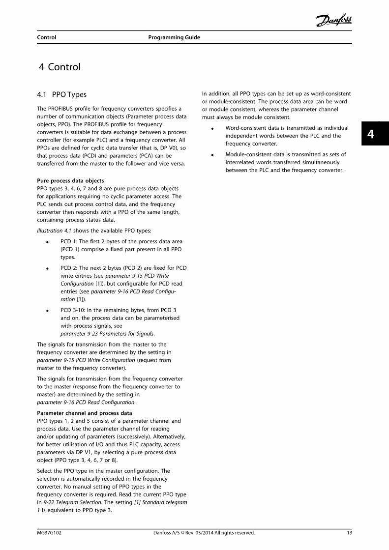
The PROFIBUS profile for frequency converters specifies anumber of communication objects (Parameter process dataobjects, PPO). The PROFIBUS profile for frequencyconverters is suitable for data exchange between a processcontroller (for example PLC) and a frequency converter. AllPPOs are defined for cyclic data transfer (that is, DP V0), sothat process data (PCD) and parameters (PCA) can betransferred from the master to the follower and vice versa.
Pure process data objectsPPO types 3, 4, 6, 7 and 8 are pure process data objectsfor applications requiring no cyclic parameter access. ThePLC sends out process control data, and the frequencyconverter then responds with a PPO of the same length,containing process status data.
Illustration 4.1 shows the available PPO types:
• PCD 1: The first 2 bytes of the process data area(PCD 1) comprise a fixed part present in all PPOtypes.
• PCD 2: The next 2 bytes (PCD 2) are fixed for PCDwrite entries (see parameter 9-15 PCD WriteConfiguration [1]), but configurable for PCD readentries (see parameter 9-16 PCD Read Configu-ration [1]).
• PCD 3-10: In the remaining bytes, from PCD 3and on, the process data can be parameterisedwith process signals, see parameter 9-23 Parameters for Signals.
The signals for transmission from the master to thefrequency converter are determined by the setting in parameter 9-15 PCD Write Configuration (request frommaster to the frequency converter).
The signals for transmission from the frequency converterto the master (response from the frequency converter tomaster) are determined by the setting in parameter 9-16 PCD Read Configuration .
Parameter channel and process dataPPO types 1, 2 and 5 consist of a parameter channel andprocess data. Use the parameter channel for readingand/or updating of parameters (successively). Alternatively,for better utilisation of I/O and thus PLC capacity, accessparameters via DP V1, by selecting a pure process dataobject (PPO type 3, 4, 6, 7 or 8).
Select the PPO type in the master configuration. Theselection is automatically recorded in the frequencyconverter. No manual setting of PPO types in thefrequency converter is required. Read the current PPO typein 9-22 Telegram Selection. The setting [1] Standard telegram1 is equivalent to PPO type 3.
In addition, all PPO types can be set up as word-consistentor module-consistent. The process data area can be wordor module consistent, whereas the parameter channelmust always be module consistent.
• Word-consistent data is transmitted as individualindependent words between the PLC and thefrequency converter.
• Module-consistent data is transmitted as sets ofinterrelated words transferred simultaneouslybetween the PLC and the frequency converter.
Control Programming Guide
MG37G102 Danfoss A/S © Rev. 05/2014 All rights reserved. 13
4 4

CTW/STW REF/MAVPCD 2Read/Write
PCD 3Read/Write
Standard telegram
1
PCD 4Read/Write
PCD 5Read/Write
PPO 4
PPO 6
PPO 7
PPO 8
Danfoss telegram
(The old PPO type 3)
PCV
CTW/STW REF/MAVPCD 2Read/Write
PCD 3Read/Write
PCD 4Read/Write
PCD 5Read/Write
CTW/STW REF/MAVPCD 2Read/Write
PCD 3Read/Write
PCD 4Read/Write
PCD 5Read/Write
PCD 6Read/Write
PCD 7Read/Write
PCD 8Read/Write
PCD 9Read/Write
CTW/STW REF/MAVPCD 2Read/Write
PCD 3Read/Write
PCD 4Read/Write
PCD 5Read/Write
PCD 6Read/Write
PCD 7Read/Write
CTW/STW REF/MAV
CTW/STW REF/MAV
PPO 3
CTW/STW REF/MAVPCD 2Read/Write
PCD 3Read/Write
PPO 2 PCV
CTW/STW REF/MAVPPO 1 PCV
130B
D91
1.10
Illustration 4.1 Available PPO Types
4.2 Process Data
Use the process data part of the PPO to control andmonitor the frequency converter via the PROFIBUS.
4.2.1 Process Control Data
Process control data (PCD) is the process data sent fromthe PLC to the frequency converter.
Master/follower
1 2 3 ....... 10
CTW MRV PCD ....... PCD
PCD write
Table 4.1 Process Control Data
PCD 1 contains a 16-bit control word, and each bit controlsa specific function of the frequency converter, seechapter 4.3 Control Profile.
PCD 2 contains a 16-bit speed setpoint in percentageformat. See chapter 4.2.3 Reference Handling.
The content of PCD 3 to PCD 10 is determined by thesettings in parameter 9-15 PCD Write Configuration and parameter 9-16 PCD Read Configuration.
4.2.2 Process Status Data
Process status data is the process data sent from thefrequency converter, and contains information about thecurrent state.
Follower master
1 2 3 ...... 10
STW MAV PCD ...... PCD
PCD read
Table 4.2 Process Status Data
PCD 1 contains a 16-bit status word, and each bit containsinformation regarding a possible state of the frequencyconverter.
PCD 2 contains per default the value of the current speedof the frequency converter in percentage format (seechapter 4.2.3 Reference Handling). PCD 2 can be configuredto contain other process signals.
Control Programming Guide
14 Danfoss A/S © Rev. 05/2014 All rights reserved. MG37G102
44

The content of PCD 3 to PCD 10 is determined by thesettings in parameter 9-16 PCD Read Configuration.
4.2.3 Reference Handling
The reference handling is an advanced mechanism thatsums up references from different sources, as shown inIllustration 4.2.
For more information on reference handling, refer to theDesign Guide of the relevant frequency converter.
Illustration 4.2 Reference
The reference, or speed setpoint, is sent via PROFIBUS andis always transmitted to the frequency converter inpercentage format as integers represented in hexadecimal(0-4000 hex).
The reference (MRV) and feedback (MAV) are always scaledequally. The setting of 3-00 Reference Range determines thescaling of the reference and feedback (MAV), seeIllustration 4.3.
Illustration 4.3 Reference (MRV) and Feedback (MAV), Scaled
NOTICEWhen 3-00 Reference Range is set to [0] Min - Max, anegative reference is handled as 0%.
The actual output of the frequency converter is limited bythe speed limit parameters Motor Low/High Speed Limit[RPM/Hz] in 4-11 Motor Speed Low Limit [RPM] to 4-14 MotorSpeed High Limit [Hz].The final speed limit is set in 4-19 Max Output Frequency.
Table 4.3 lists the reference (MRV) and the feedback (MAV)formats.
MRV/MAV Integer in hex Integer in decimal
100% 4000 16,384
75% 3000 12,288
50% 2000 8,192
25% 1000 4,096
0% 0 0
-25% F000 -4,096
-50% E000 -8,192
-75% D000 -12,288
-100% C000 -16,384
Table 4.3 Reference/Feedback (MRV/MAV) Format
NOTICENegative numbers are formed as complement of 2.
NOTICEThe data type for MRV and MAV is a N2 16-bitstandardised value, expressing a range from -200% to+200% (8001 to 7FFF).
ExampleThe following settings determine the speed, as shown inTable 4.4:
• 1-00 Configuration Mode set to [0] Speed openloop.
• 3-00 Reference Range set to [0] Min-Max.
• 3-02 Minimum Reference set to 100 RPM.
• 3-03 Maximum Reference set to 3000 RPM.
MRV/MAV Actual speed [RPM]
0% 0 hex 100
25% 1000 hex 825
50% 2000 hex 1550
75% 3000 hex 2275
100% 4000 hex 3000
Table 4.4 Actual Speed for MRV/MAV
4.2.4 Process Control Operation
In process control operation, 1-00 Configuration Mode is setto [3] Process.The reference range in 3-00 Reference Range is always [0]Min - Max.
Control Programming Guide
MG37G102 Danfoss A/S © Rev. 05/2014 All rights reserved. 15
4 4

• MRV represents the process setpoint.
• MAV expresses the actual process feedback(range ±200%).
4.2.5 Influence of the Digital InputTerminals upon FC Control Mode
Set the influence of the digital input terminals uponcontrol of the frequency converter in 8-50 Coasting Selectto 8-56 Preset Reference Select.
NOTICEThe setting of 8-01 Control Site overrules the settings in8-50 Coasting Select to 8-56 Preset Reference Select. Thesetting of terminal 37 Coast stop (safe) overrules anyother parameter.
Each of the digital input signals can be programmed tologic AND, logic OR, or to have no relation to thecorresponding bit in the control word. In this way thefollowing signal sources initiate a specific controlcommand, for example stop/coast:
• fieldbus only,
• fieldbus AND digital input, or
• either fieldbus OR digital input terminal.
CAUTIONTo control the frequency converter via PROFIBUS, set8-50 Coasting Select to either [1] Bus , or to [2] Logic AND,and set 8-01 Control Site to [0] or [2].
For more detailed information and examples of logicalrelationship options, see chapter 8 Troubleshooting.
4.3 Control Profile
Control the frequency converter according to
• the PROFIdrive profile, see chapter 4.4 PROFIdriveControl Profile, or
• the Danfoss FC control profile, seechapter 4.5 Danfoss FC Control Profile.
Select the desired control profile in parameter 8-10 ControlWord Profile. The choice of profile affects the control andstatus word only.
Chapter 4.4 PROFIdrive Control Profile andchapter 4.5 Danfoss FC Control Profile provide a detaileddescription of control and status data.
4.4 PROFIdrive Control Profile
This section describes the functionality of the control wordand status word in the PROFIdrive profile.
4.4.1 Control Word according to PROFIdriveProfile (CTW)
The control word is used to send commands from a master(e.g. a PC) to a follower.
Bit Bit=0 Bit=1
00 OFF 1 ON 1
01 OFF 2 ON 2
02 OFF 3 ON 3
03 Coasting No coasting
04 Quick stop Ramp
05 Hold frequency output Use ramp
06 Ramp stop Start
07 No function Reset
08 Jog 1 OFF Jog 1 ON
09 Jog 2 OFF Jog 2 ON
10 Data invalid Data valid
11 No function Slow down
12 No function Catch up
13 Parameter set-up Selection lsb
14 Parameter set-up Selection msb
15 No function Reverse
Table 4.5 Control Word Bits
Explanation of the control bitsBit 00, OFF 1/ON 1Normal ramp stops using the ramp times of the actualselected ramp.Bit 00="0" leads to the stop and activation of the outputrelay 1 or 2 if the output frequency is 0 Hz and if [Relay123] has been selected in 5-40 Function Relay.When bit 0="1", the frequency converter is in State 1:“Switching on inhibited”.Refer to Illustration 4.4.
Bit 01, OFF 2/ON 2Coasting stop.When bit 01="0", a coasting stop and activation of theoutput relay 1 or 2 occurs if the output frequency is 0 Hzand if [Relay 123] has been selected in 5-40 Function Relay.When bit 01="1", the frequency converter is in State 1:“Switching on inhibited”. Refer to Illustration 4.4.
Bit 02, OFF 3/ON 3Quick stop using the ramp time of 3-81 Quick Stop RampTime.When bit 02="0", a quick stop and activation of the outputrelay 1 or 2 occurs if the output frequency is 0 Hz and if[Relay 123] has been selected in 5-40 Function Relay.When bit 02="1", the frequency converter is in State 1:“Switching on inhibited”.
Control Programming Guide
16 Danfoss A/S © Rev. 05/2014 All rights reserved. MG37G102
44

Refer to Illustration 4.4.
Bit 03, Coasting/No coastingCoasting stop Bit 03="0" leads to a stop.When bit 03="1", the frequency converter can start if theother start conditions are fulfilled.
NOTICEThe selection in 8-50 Coasting Select determines how bit03 is linked with the corresponding function of thedigital inputs.
Bit 04, Quick stop/RampQuick stop using the ramp time of 3-81 Quick Stop RampTime.When bit 04="0", a quick stop occurs.When bit 04="1", the frequency converter can start if theother start conditions are fulfilled.
NOTICEThe selection in parameter 8-51 Quick Stop Selectdetermines how bit 04 is linked with the correspondingfunction of the digital inputs.
Bit 05, Hold frequency output/Use rampWhen bit 05="0", the current output frequency is beingmaintained even if the reference value is modified.When bit 05="1", the frequency converter can perform itsregulating function again; operation occurs according tothe respective reference value.
Bit 06, Ramp stop/StartNormal ramp stop using the ramp times of the actualramp as selected. In addition, activation of the output relay01 or 04 if the output frequency is 0 Hz if Relay 123 hasbeen selected in 5-40 Function Relay. Bit 06="0" leads to astop. When bit 06="1", the frequency converter can start ifthe other start conditions are fulfilled.
NOTICEThe selection in 8-53 Start Select determines how bit 06is linked with the corresponding function of the digitalinputs.
Bit 07, No function/ResetReset after switching off. Acknowledges event in faultbuffer.When bit 07="0", no reset occurs.When there is a slope change of bit 07 to "1", a resetoccurs after switching off.
Bit 08, Jog 1 OFF/ONActivation of the pre-programmed speed in 8-90 Bus Jog 1Speed. JOG 1 is only possible if bit 04="0" and bit00-03="1".
Bit 09, Jog 2 OFF/ONActivation of the pre-programmed speed in 8-91 Bus Jog 2Speed. JOG 2 is only possible if bit 04="0" and bit00-03="1".
Bit 10, Data invalid/validUsed to tell the frequency converter whether the controlword is to be used or ignored. Bit 10=“0” causes thecontrol word to be ignored, giving the opportunity to turnoff the control word when updating/reading parameters.Bit 10=“1” causes the control word to be used. Thisfunction is relevant, because the control word is alwayscontained in the telegram, regardless of which type oftelegram is used.
Bit 11, No function/Slow downUsed to reduce the speed reference value by the amountgiven in 3-12 Catch up/slow Down Value value.When bit 11="0", no modification of the reference valueoccurs.When bit 11="1", the reference value is reduced.
Bit 12, No function/Catch upUsed to increase the speed reference value by the amountgiven in 3-12 Catch up/slow Down Value.When bit 12="0", no modification of the reference valueoccurs.When bit 12="1", the reference value is increased.If both slowing down and accelerating are activated (bit 11and 12="1"), slowing down has priority, and the speedreference value is reduced.
Bits 13/14, Set-up selectionBits 13 and 14 are used to select between the 4 parameterset-ups according to Table 4.6.
The function is only possible if Multi Set-up has beenselected in 0-10 Active Set-up. The selection in 8-55 Set-upSelect determines how bits 13 and 14 are linked with thecorresponding function of the digital inputs. Changing set-up while running is only possible if the set-ups have beenlinked in 0-12 This Set-up Linked to.
Set-up Bit 13 Bit 14
1 0 0
2 1 0
3 0 1
4 1 1
Table 4.6 Parameter Set-ups
Bit 15, No function/ReverseBit 15=“0” causes no reversing.Bit 15=“1” causes reversing.
NOTICEIn the factory setting, reversing is set to digital in parameter 8-54 Reversing Select.
NOTICEBit 15 causes reversing only when Ser. communication,Logic or or Logic and is selected.
Control Programming Guide
MG37G102 Danfoss A/S © Rev. 05/2014 All rights reserved. 17
4 4

4.4.2 Status Word according to PROFIdriveProfile (STW)
The status word is used to notify a master (e.g. a PC)about the status of a follower.
Bit Bit=0 Bit=1
00 Control not ready Control ready
01 Drive not ready Drive ready
02 Coasting Enable
03 No error Trip
04 OFF 2 ON 2
05 OFF 3 ON 3
06 Start possible Start not possible
07 No warning Warning
08 Speed ≠ reference Speed = reference
09 Local operation Bus control
10 Out of frequency limit Frequency limit ok
11 No operation In operation
12 Drive OK Stopped, autostart
13 Voltage OK Voltage exceeded
14 Torque OK Torque exceeded
15 Timer OK Timer exceeded
Table 4.7 Status Word Bits
Explanation of the status bitsBit 00, Control not ready/ReadyWhen bit 00="0", bit 00, 01 or 02 of the control word is "0"(OFF 1, OFF 2 or OFF 3) - or the frequency converter isswitched off (trip).When bit 00="1", the frequency converter control is ready,but there is not necessarily power supply to the unitpresent (in the event of external 24 V supply of the controlsystem).
Bit 01, VLT not ready/ReadySame significance as bit 00, however, there is a supply ofthe power unit. The frequency converter is ready when itreceives the necessary start signals.
Bit 02, Coasting/EnableWhen bit 02="0", bit 00, 01 or 02 of the control word is "0"(OFF 1, OFF 2 or OFF 3 or coasting) - or the frequencyconverter is switched off (trip).When bit 02="1", bit 00, 01 or 02 of the control word is"1"; the frequency converter has not tripped.
Bit 03, No error/TripWhen bit 03="0", no error condition of the frequencyconverter exists.When bit 03="1", the frequency converter has tripped andrequires a reset signal before it can start.
Bit 04, ON 2/OFF 2When bit 01 of the control word is "0", bit 04="0".When bit 01 of the control word is "1", bit 04="1".
Bit 05, ON 3/OFF 3When bit 02 of the control word is "0", bit 05="0".
When bit 02 of the control word is "1", bit 05="1".
Bit 06, Start possible/Start not possibleIf PROFIdrive has been selected in parameter 8-10 ControlWord Profile, bit 06 is "1" after a switch-off acknowl-edgment, after activation of OFF2 or OFF3, and afterswitching on the mains voltage. Start not possible is reset,with bit 00 of the control word being set to "0" and bit 01,02 and 10 being set to "1".
Bit 07, No warning/WarningBit 07=“0” means that there are no warnings.Bit 07=“1” means that a warning has occurred.
Bit 08, Speed≠reference/Speed=referenceWhen bit 08="0", the current speed of the motor deviatesfrom the set speed reference value. This may occur, forexample, when the speed is being changed during start/stop through ramp up/down.When bit 08="1", the current speed of the motorcorresponds to the set speed reference value.
Bit 09, Local operation/Bus controlBit 09="0" indicates that the frequency converter has beenstopped with [Stop] on the LCP, or that [Linked to hand]or [Local] has been selected in 3-13 Reference Site.When bit 09="1", the frequency converter can becontrolled through the serial interface.
Bit 10, Out of frequency limit/Frequency limit OKWhen bit 10="0", the output frequency is outside the limitsset in 4-52 Warning Speed Low and 4-53 Warning SpeedHigh.When bit 10="1", the output frequency is within theindicated limits.
Bit 11, No operation/OperationWhen bit 11="0", the motor does not turn.When bit 11="1", the frequency converter has a startsignal, or the output frequency is higher than 0 Hz.
Bit 12, Drive OK/Stopped, autostartWhen bit 12="0", there is no temporary overloading of theinverter.When bit 12="1", the frequency converter has stopped dueto overloading. However, the frequency converter has notswitched off (trip) and starts again after the overloadinghas ended.
Bit 13, Voltage OK/Voltage exceededWhen bit 13="0", the voltage limits of the frequencyconverter are not exceeded.When bit 13="1", the direct voltage in the intermediatecircuit of the frequency converter is too low or too high.
Bit 14, Torque OK/Torque exceededWhen bit 14="0", the motor torque is below the limitselected in 4-16 Torque Limit Motor Mode and 4-17 TorqueLimit Generator Mode.When bit 14="1", the limit selected in 4-16 Torque LimitMotor Mode or 4-17 Torque Limit Generator Mode isexceeded.
Control Programming Guide
18 Danfoss A/S © Rev. 05/2014 All rights reserved. MG37G102
44

Bit 15, Timer OK/Timer exceededWhen bit 15="0", the timers for the thermal motorprotection and thermal frequency converter protectionhave not exceeded 100%.
When bit 15="1", one of the timers has exceeded 100%.
4.4.3 PROFIdrive State Transition Diagram
In the PROFIdrive control profile, the control bits:
• 0 to 3 perform the basic start-up/power down functions.
• 4-15 perform application-oriented control.
Illustration 4.4 shows the basic state transition diagram, where control bits 0 to 3 control the transitions, and thecorresponding status bit indicates the actual state. The black bullets indicate the priority of the control signals, where fewerbullets indicate lower priority, and more bullets indicate higher priority.
130B
D80
6.10
Illustration 4.4 PROFIdrive State Transition Diagram
Control Programming Guide
MG37G102 Danfoss A/S © Rev. 05/2014 All rights reserved. 19
4 4

4.5 Danfoss FC Control Profile
4.5.1 Control Word according to FC Profile(CTW)
To select Danfoss FC protocol in the control word, set parameter 8-10 Control Word Profile to [0] frequencyconverter profile. Use the control word to send commandsfrom a master (PLC or PC) to a follower (frequencyconverter).
Bit Bit value=0 Bit value=1
00 Reference value External selection lsb
01 Reference value External selection msb
02 DC brake Ramp
03 Coasting No coasting
04 Quick stop Ramp
05 Hold output frequency Use ramp
06 Ramp stop Start
07 No function Reset
08 No function Jog
09 Ramp 1 Ramp 2
10 Data invalid Data valid
11 No function Relay 01 active
12 No function Relay 04 active
13 Parameter set-up selection lsb
14 Parameter set-up selection msb
15 No function Reverse
Table 4.8 Bit Values for FC Control Word
Explanation of the control bitsBits 00/01 Reference valueBits 00 and 01 are used to select between the 4 referencevalues, which are pre-programmed in 3-10 Preset Referenceaccording to Table 4.9.
NOTICEIn 8-56 Preset Reference Select a selection is made todefine how bit 00/01 gates with the correspondingfunction on the digital inputs.
Bit 01 Bit 00 Programmedref. value
Parameter
0 0 1 [0] 3-10 Preset Reference
0 1 2 [1] 3-10 Preset Reference
1 0 3 [2] 3-10 Preset Reference
1 1 4 [3] 3-10 Preset Reference
Table 4.9 Programmed Reference Values for Bits
Bit 02, DC brakeBit 02=“0” - leads to DC braking and stop. Braking currentand duration are set in 2-01 DC Brake Current and 2-02 DCBraking Time.Bit 02=“1” - leads to ramping.
Bit 03, CoastingBit 03=“0” - causes the frequency converter immediately tocoast the motor to a standstill.Bit 03=“1” - enables the frequency converter to start themotor if the other starting conditions have been fulfilled.
NOTICEIn 8-50 Coasting Select a selection is made to define howbit 03 gates with the corresponding function on a digitalinput.
Bit 04, Quick stopBit 04=“0” - causes a quick stop, ramping the motor speeddown to stop via 3-81 Quick Stop Ramp Time.Bit 04=“1” - the frequency converter ramps the motorspeed down to stop via 3-42 Ramp 1 Ramp Down Time or3-52 Ramp 2 Ramp Down Time.
Bit 05, Hold output frequencyBit 05=“0” - causes the present output frequency (in Hz) tofreeze. The frozen output frequency can only be changedwith the digital inputs (5-10 Terminal 18 Digital Input to5-15 Terminal 33 Digital Input) programmed to Speed upand Speed down.Bit 05=“1” - use ramp.
NOTICEIf Freeze output is active, stop the frequency converterwith
• Bit 03 Coasting stop.
• Bit 02 DC braking.
• Digital input (5-10 Terminal 18 Digital Input to5-15 Terminal 33 Digital Input) programmed toDC braking, Coasting stop, or Reset and coastingstop.
Bit 06, Ramp stop/startBit 06=“0” - causes a stop in which the motor speed isramped down to stop via the selected ramp downparameter.Bit 06=“1" - permits the frequency converter to start themotor, if the other starting conditions have been fulfilled.
NOTICEIn 8-53 Start Select a selection is made to define how bit06 Ramp stop/start gates with the correspondingfunction on a digital input.
Bit 07, ResetBit 07="0" - does not cause a reset.Bit 07="1" - causes the reset of a trip. Reset is activated onthe signal’s leading edge, that is, when changing fromlogic "0" to logic "1".
Bit 08, JogBit 08="0" - no function.
Control Programming Guide
20 Danfoss A/S © Rev. 05/2014 All rights reserved. MG37G102
44

Bit 08="1" - 3-19 Jog Speed [RPM] determines the outputfrequency.
Bit 09, Selection of ramp 1/2Bit 09="0" - ramp 1 is active (3-40 Ramp 1 Type to3-47 Ramp 1 S-ramp Ratio at Decel. Start).Bit 09="1" - ramp 2 (3-50 Ramp 2 Type to 3-57 Ramp 2 S-ramp Ratio at Decel. Start) is active.
Bit 10, Data not valid/Data validTells the frequency converter whether it should use orignore the control word.Bit 10="0" - the control word is ignored.Bit 10="1" - the control word is used. This function isrelevant, because the control word is always contained inthe telegram, regardless of which type of telegram is used.Thus, it is possible to turn off the control word, if it is notwished to use it when updating or reading parameters.
Bit 11, Relay 01Bit 11="0" - relay 01 not activated.Bit 11="1" - relay 01 activated, provided control word bit11 has been selected in 5-40 Function Relay.
Bit 12, Relay 04Bit 12="0" - relay 04 has not been activated.Bit 12="1" - relay 04 has been activated, provided Controlword bit 12 has been selected in 5-40 Function Relay.
Bit 13/14, Selection of set-upBits 13 and 14 are used to select from the 4 menu set-upsaccording to Table 4.10:
The function is only possible when Multi-Set-ups is selectedin 0-10 Active Set-up.
Set-up Bit 14 Bit 13
1 0 0
2 0 1
3 1 0
4 1 1
Table 4.10 Selection of Set-up
NOTICEIn 8-55 Set-up Select a selection is made to define howbit 13/14 gates with the corresponding function on thedigital inputs.
Bit 15 ReverseBit 15="0" - no reversing.Bit 15="1" - reversing.
4.5.2 Status Word according to FC Profile(STW)
The status word is used to inform the master (e.g. a PC) ofthe operation mode of the slave (frequency converter).
Refer to chapter 7 Application Examples for an example of astatus word telegram using PPO type 3.
Bit Bit=0 Bit=1
00 Control not ready Control ready
01 Frequency converternot ready
Frequency converter ready
02 Coasting Enable
03 No error Trip
04 No error Error (no trip)
05 Reserved -
06 No error Triplock
07 No warning Warning
08 Speed reference Speed=reference
09 Local operation Bus control
10 Out of frequency limit Frequency limit ok
11 No operation In operation
12 Frequency converter OK Stopped, autostart
13 Voltage OK Voltage exceeded
14 Torque OK Torque exceeded
15 Timer OK Timer exceeded
Table 4.11 Definition of Status Bits
Explanation of the status bitsBit 00, Control not ready/readyBit 00="0" - the frequency converter has tripped.Bit 00="1" - the frequency converter controls are ready, butthe power component is not necessarily receiving anypower supply (in case of 24 V external supply to controls).
Bit 01, frequency converter readyBit 01="0" - the frequency converter is not ready foroperation.Bit 01="1" - the frequency converter is ready for operation,but there is an active coasting command via the digitalinputs or via serial communication.
Bit 02, Coasting stopBit 02="0" - the frequency converter has released themotor.Bit 02="1" - the frequency converter can start the motorwhen a start command is given.
Bit 03, No error/TripBit 03="0" - the frequency converter is not in fault mode.Bit 03="1" - the frequency converter is tripped, and that areset signal is required to re-establish operation.
Bit 04, No error/Error (no trip)Bit 04="0" - the frequency converter is not in fault mode.Bit 04=“1” - there is a frequency converter error but notrip.
Bit 05, Not usedBit 05 is not used in the status word.
Bit 06, No error/triplockBit 06="0" - the frequency converter is not in fault mode.Bit 06=“1” - the frequency converter is tripped, and locked.
Control Programming Guide
MG37G102 Danfoss A/S © Rev. 05/2014 All rights reserved. 21
4 4

Bit 07, No warning/WarningBit 07="0" - there are no warnings.Bit 07="1" - a warning has occurred.
Bit 08, Speed reference/Speed = referenceBit 08="0" - the motor is running, but the present speed isdifferent from the preset speed reference. It could, forexample, be the case while the speed is being ramped up/down during start/stop.Bit 08="1" - the present motor present speed matches thepreset speed reference.
Bit 09, Local operation/bus controlBit 09="0" - [Stop/Reset] is pressed on the LCP, or thatLocal control in 3-13 Reference Site is selected. It is notpossible to control the frequency converter via serialcommunication.Bit 09="1" - it is possible to control the frequencyconverter via the fieldbus/serial communication.
Bit 10, Out of frequency limitBit 10="0" - the output frequency has reached the value in4-11 Motor Speed Low Limit [RPM] or 4-13 Motor Speed HighLimit [RPM].Bit 10="1" - the output frequency is within the definedlimits.
Bit 11, No operation/In operationBit 11="0" - the motor is not running.Bit 11="1" - the frequency converter has a start signal orthe output frequency is higher than 0 Hz.
Bit 12, frequency converter OK/Stopped, auto startBit 12="0" - there is no temporary over-temperature on thefrequency converter.Bit 12="1" - the frequency converter has stopped becauseof over-temperature, but the frequency converter has nottripped and resumes operation once the over-temperaturestops.
Bit 13, Voltage OK/Limit exceededBit 13="0" - there are no voltage warnings.Bit 13="1" - the DC voltage in the frequency convertersintermediate circuit is too low or too high.
Bit 14, Torque OK/Limit exceededBit 14="0" - the motor current is lower than the torquelimit selected in 4-16 Torque Limit Motor Mode or4-17 Torque Limit Generator Mode.Bit 14="1" - the torque limits in 4-16 Torque Limit MotorMode and 4-17 Torque Limit Generator Mode have beenexceeded.
Bit 15, Timer OK/Limit exceededBit 15="0" - the timers for motor thermal protection andfrequency converter thermal protection, have notexceeded 100%.Bit 15="1" - one of the timers has exceeded 100%.
4.6 Synchronise and Freeze
The control commands SYNC/UNSYNC and FREEZE/UNFREEZE are broadcast functions.
SYNC/UNSYNC is used to synchronise control commandsand/or speed reference to all the connected frequencyconverters.
FREEZE/UNFREEZE is used to freeze the status feedback inthe slaves to get synchronized feedback from allconnected slaves.
The synchronise and freeze commands affect only processdata (the PCD part of the PPO).
4.6.1 SYNC/UNSYNC
SYNC/UNSYNC can be used to obtain simultaneousreactions in several slaves, for example synchronised start,stop or speed change.A SYNC command freezes the relevant control word andspeed reference. Incoming process data are stored but notused until a new SYNC command or a UNSYNC commandis received.An UNSYNC command stops the synchronisationmechanism and enables normal DP data exchange.
4.6.2 FREEZE/UNFREEZE
FREEZE/UNFREEZE can be used for simultaneous reading ofprocess data, for example, output current, from severalslaves.
A FREEZE command freezes the actual values and uponrequest the slave sends back the value that was presentwhen the FREEZE command was received.
Upon receipt of an UNFREEZE command the values onceagain is continuously updated and the slave returns apresent value, for example, a value generated byconditions at present time.
The values is updated when a new FREEZE or UNFREEZEcommand is received.
Control Programming Guide
22 Danfoss A/S © Rev. 05/2014 All rights reserved. MG37G102
44

5 Parameter Access
5.1 Parameter Access in General
In an automated system, frequency converter parameterscan be accessed either from the process controller (that is,PLC), or from various kinds of HMI equipment. Forparameter access from controllers and HMI, observe thefollowing:
Parameters are located in 4 separate set-ups. Parameteraccess in the frequency converter is performed via severalseparated parameter channels. Use the separated channelsindividually to access a certain parameter set-up. Select thedesired set-up in 0-11 Edit Set-up or 9-70 Edit Set-up.
Using the above mechanism it is possible to read or writeto and from parameters in a certain set-up from a masterclass 1, for example a PLC. And it is also possible tosimultaneously access parameters in a different set-upfrom a master class 2, for example a PC tool, withoutinterfering with the set-up selection for the programmingsources.
Parameters can be accessed via the following sites:
• LCP
• FC Protocol on RS485 or USB
• Cyclical data access on DP-V0 (PCV Channel)
• PROFIBUS Master Class 1
• PROFIBUS Master Class 2 (3 connections possible)
NOTICEAlthough the parameter channels are separated, dataconflict can occur if write to parameters is made from anHMI unit into a set-up which is actively in use by thefrequency converter or the process controller (e.g. aPLC).
5.1.1 Data Store
Parameters write via the PCV channel (DP-V0) is stored inRAM only. If data has to be stored in non-volatile memory,the 9-71 Profibus Save Data Values can be used for storingone or more set-ups.
Using DP-V1 access, store parameters either in RAM ornon-volatile memory by choice of a specific write-requestcommand. At any time, store non-stored data in non-volatile memory by activating 9-71 Profibus Save DataValues.
5.1.2 Read/Write in Double Word Format
Using the special request IDs 0X51 (read) and 0X52 (write),it is possible to read and write to all parameters containingnumeric values in a general format of double word. Thevalue element must be right aligned and unused MSBsfilled with zeros.
Example: Read of a parameter of type U8 is transmitted as00 00 00 xx, where xx is the value to be transmitted. Thedata type signalled by the telegram is 43h (dword).
5.1.3 PROFIBUS DP-V1
Using the acyclic DP-V1 transmission, it is possible to readand write parameter values, as well as to read a number ofdescriptive attributes for each parameter. Access toparameters via DP-V1 is described in chapter 5.2 DP-V1Parameter Access.
5.1.4 PROFIBUS DP-V0/PCV Channel
Parameter access via the PCV channel is performed usingPROFIBUS DP-V0 cyclic data exchange, where the PCVchannel is part of the PPOs described in chapter 4.1 PPOTypes. Using the PCV channel, it is possible to read andwrite parameter values, as well as read a number ofdescriptive attributes for each parameter. The functionalityof the PCV channel is described in chapter 5.3 PCVParameter Access.
NOTICEObject and data types common to both DP-V1 and PCVparameter access are listed in chapter 5 Parameter Access.
5.2 DP-V1 Parameter Access
This section is useful for the developer with someexperience in:
• PLC programs with PROFIBUS master class 1functionality.
• PC applications with PROFIBUS master class 2functionality.
For more detailed instructions in use of the DP-V1function, refer to the PROFIBUS master manual from thePLC supplier.
Parameter Access Programming Guide
MG37G102 Danfoss A/S © Rev. 05/2014 All rights reserved. 23
5 5

5.2.1 PROFIBUS DP-V1 Introduction
The PROFIBUS DP extension DP-V1 offers acyclicalcommunication in addition to the cyclical data communi-cation of DP-V0. This feature is possible using a DP masterclass 1 (for example, PLC), as well as a DP master class 2(for example, PC Tool).
Cyclical communication means that data transfer takesplace continuously with a certain refresh rate. This is theknown DP-V0 function normally used for quick update ofI/O process data.
Acyclical communication takes the form of a once-off datatransfer event, mainly used for read/write from and toparameters from process controllers, PC-based tools ormonitoring systems.
5.2.2 Features of a Master Class 1Connection
• Cyclical data exchange (DP-V0)
• Acyclical read/write from and to parameters
A master class 1 is used as the process controller (eitherPLC or PC-based), responsible for commands, speedreference, status of the application, etc. The master class 1acyclical connection can be used for general parameteraccess in the slaves. However, the acyclical connection isfixed, and cannot be changed during operation.
5.2.3 Features of a Master Class 2Connection
• Initiate/abort acyclical connection
• Acyclical read/write from and to parameters
The master class 2 acyclical connection is typically used forconfiguration or commissioning tools for easy access toeach parameter in any slave in the system. The acyclicalconnection can be dynamically established (initiate) orremoved (abort) even when a master class 1 is active onthe network.
5.2.4 Services Overview
Mastertype
ServiceRead Write Data
transportInitiate Abort Alarm
readdatafromfollower
writedata tofollower
read andwrite data
open aconnection
close aconnection
MasterClass 1
yes yes yes - - -
MasterClass 2
yes yes yes yes yes -
Table 5.1 Services Overview
5.2.5 Principle of Data Exchange byPROFIBUS DP-V1
In a DP cycle, the master class 1 (MC1) first updates thecyclical process data for all slaves in the system. The MC1then sends one acyclical message to one slave. If a masterclass 2 (MC2) is connected, the MC1 hands over the busrights to MC2, which is then permitted to send oneacyclical message to one slave. The token is then handedback to the MC1, and a new DP cycle begins.
Illustration 5.1 DP Cycle
• MC: Master class
• C1...Cn: Cyclical data
• AC1: Acyclical data master class 1
• AC2: Acyclical data master class 2
PROFIBUS DP services are activated via specific serviceaccess points (SAP). Table 5.2 shows the SAP specified foracyclical communication.
MasterSAP
Follower SAP Meaning
50 (32H) 49 (31H) Master Class 2: Initiate request50 (32H) 0..48 (0..30H) Master Class 2: Abort, read, write, data
transfer51 (33H) 50, 51 (32H,
33H)Master Class 2: Alarm
51 (33H) 51 (33H) Master Class 2: Read, write
Table 5.2 Service Access Points (SAP)
5.2.6 DP-V1 Features for Parameter Access
This section describes how to use DP-V1 for accessing VLTparameters.
The standard PROFIBUS DP-V1 read and write services arenot sufficient for accessing the many parameters andattributes in the frequency converter. For this reason, thePROFIdrive parameter channel is defined. Using thisparameter read/write is performed by addressing a singleDP-V1 object in the frequency converter as shown in theexample, Table 5.3.
Parameter Access Programming Guide
24 Danfoss A/S © Rev. 05/2014 All rights reserved. MG37G102
55

For a detailed description of the DP-V1 commandhandling, refer to the PROFIBUS DP-V1 Design Guide.
ExampleSlot=0Index=47
PROFIBUStelegramheader
Data unit PROFIBUS-telegramtrailer
DP-V1Command/response
PROFIdrive V3.0 parameterchannel
DU0
DU1
DU2
DU3
Req./Res.Header
Data
Table 5.3 General Structure for Telegram
Use the DP-V1 command/response part for the standardDP-V1 read/write on slot 0, index 47 data block.
Use the PROFIdrive V3 parameter channel to accessspecific parameter data in the frequency converter.
5.2.7 DP-V1 Read/Write Services
Table 5.4 shows the content of the DP-V1 command/Response headers and their possible attributes.
DU byte Value Meaning Specified0 Function
number0x48
Idle REQ, RES
0x51 Data transport REQ,RES
0x56 Resource managerREQ
0x57 Initiate REQ, RES0x58 Abort REQ 0x5C Alarm REQ, RES0x5E Read REQ, RES 0x5F Write REQ, RES0xD1 Data transport
negative response
0xD7 Initiate negativeresponse
0xDC Alarm negativeresponse
0xDE Read negativeresponse
0xDF Write negativeresponse
1 Always zero Slot number DPV12 47 Index DPV13 xx Data length DPV14..n User data PNO drive profile V3.0
Table 5.4 DP-V1 Command/Response Headers
5.2.8 DP-V1 Acyclical Parameter Channel
Use the PROFIdrive parameter channel for read and writeaccess to parameter values and attributes.
• Parameter values of simple variable, array andvisible string.
• Parameter description elements such as type,minimum/maximum value, and so on.
• Descriptive text for parameter values.
• Access to multiple parameters in one telegram isalso possible.
Table 5.5 shows the structure of the PROFIdrive parameterchannel.
PROFIBUS DP-V1 telegram for read/write from or to afrequency converter parameter:
PROFIBUStelegramheader
Data unit PROFIBUStelegramtrailer
DP-V1command/response
PROFIdrive V3.0parameter channel
DU0
DU1
DU2
DU3
Req./Res.Header
Data
Table 5.5 Structure of the PROFIdrive Parameter Channel
Table 5.6 shows the principle structure of the PROFIdriveparameter channel.
The DP-V1 parameter request telegram consists of 3 datablocks:
• A request header, which defines the request (reador write), and the number of parameters toaccess. The master sets the request reference, anduses this information to evaluate the response.
• An address field, where all addressing attributesof the desired parameters are defined.
• A data field, where all parameter data values areplaced.
DP-V1 Parameter request Byte no.
Requestheader
Request reference 0Request ID 1Axis 2
Address field No. of parameters 3Attribute 4No. of elements 5Parameter no. 6
7Sub index 8
9n'th parameter no. 4+6*(n-1) ...
Data field Data format 4+6*nNo. of values (4+6*n)+1Values (4+6*n)+2n'th data value ...
Table 5.6 Principle Structure of the PROFIdrive Parameter Channel
The DP-V1 parameter response telegram consists of 2 datablocks:
• A response header, which indicates if the requestis performed without errors (response ID), thenumber of parameters, and the request reference
Parameter Access Programming Guide
MG37G102 Danfoss A/S © Rev. 05/2014 All rights reserved. 25
5 5
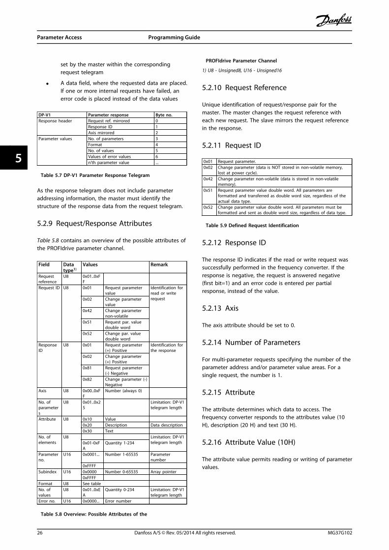
set by the master within the correspondingrequest telegram
• A data field, where the requested data are placed.If one or more internal requests have failed, anerror code is placed instead of the data values
DP-V1 Parameter response Byte no.Response header Request ref. mirrored 0
Response ID 1Axis mirrored 2
Parameter values No. of parameters 3Format 4No. of values 5Values of error values 6n'th parameter value ...
Table 5.7 DP-V1 Parameter Response Telegram
As the response telegram does not include parameteraddressing information, the master must identify thestructure of the response data from the request telegram.
5.2.9 Request/Response Attributes
Table 5.8 contains an overview of the possible attributes ofthe PROFIdrive parameter channel.
Field Datatype1)
Values Remark
Requestreference
U8 0x01..0xFF
Request ID U8 0x01 Request parametervalue
Identification forread or writerequest0x02 Change parameter
value0x42 Change parameter
non-volatile0x51 Request par. value
double word0x52 Change par. value
double wordResponseID
U8 0x01 Request parameter(+) Positive
Identification forthe response
0x02 Change parameter(+) Positive
0x81 Request parameter(-) Negative
0x82 Change parameter (-)Negative
Axis U8 0x00..0xFF
Number (always 0)
No. ofparameters
U8 0x01..0x25
Limitation: DP-V1telegram length
Attribute U8 0x10 Value0x20 Description Data description0x30 Text
No. ofelements
U8 Limitation: DP-V1telegram length0x01-0xF
AQuantity 1-234
Parameterno.
U16 0x0001... Number 1-65535 Parameternumber
0xFFFFSubindex U16 0x0000 Number 0-65535 Array pointer
0xFFFF Format U8 See tableNo. ofvalues
U8 0x01..0xEA
Quantity 0-234 Limitation: DP-V1telegram length
Error no. U16 0x0000... Error number
Table 5.8 Overview: Possible Attributes of the
PROFIdrive Parameter Channel
1) U8 - Unsigned8, U16 - Unsigned16
5.2.10 Request Reference
Unique identification of request/response pair for themaster. The master changes the request reference witheach new request. The slave mirrors the request referencein the response.
5.2.11 Request ID
0x01 Request parameter.0x02 Change parameter (data is NOT stored in non-volatile memory,
lost at power cycle).0x42 Change parameter non-volatile (data is stored in non-volatile
memory).0x51 Request parameter value double word. All parameters are
formatted and transferred as double word size, regardless of theactual data type.
0x52 Change parameter value double word. All parameters must beformatted and sent as double word size, regardless of data type.
Table 5.9 Defined Request Identification
5.2.12 Response ID
The response ID indicates if the read or write request wassuccessfully performed in the frequency converter. If theresponse is negative, the request is answered negative(first bit=1) and an error code is entered per partialresponse, instead of the value.
5.2.13 Axis
The axis attribute should be set to 0.
5.2.14 Number of Parameters
For multi-parameter requests specifying the number of theparameter address and/or parameter value areas. For asingle request, the number is 1.
5.2.15 Attribute
The attribute determines which data to access. Thefrequency converter responds to the attributes value (10H), description (20 H) and text (30 H).
5.2.16 Attribute Value (10H)
The attribute value permits reading or writing of parametervalues.
Parameter Access Programming Guide
26 Danfoss A/S © Rev. 05/2014 All rights reserved. MG37G102
55
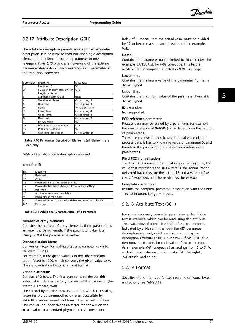
5.2.17 Attribute Description (20H)
The attribute description permits access to the parameterdescription. It is possible to read out one single descriptionelement, or all elements for one parameter in onetelegram. Table 5.10 provides an overview of the existingparameter description, which exists for each parameter inthe frequency converter.
Sub-index Meaning Data type1 Identifier ID V22 Number of array elements or
length or stringU16
3 Standardisation factor float4 Variable attribute Octet string 25 Reserved Octet string 46 Name Visible string 167 Lower limit Octet string 48 Upper limit Octet string 49 Reserved Octet string 210 ID extension V211 PCD reference parameter U1612 PCD normalisation V20 Complete description Octet string 46
Table 5.10 Parameter Description Elements (all Elements areRead-only)
Table 5.11 explains each description element.
Identifier ID
Bit Meaning15 Reserved14 Array13 Parameter value can be reset only.12 Parameter has been changed from factory setting.11 Reserved10 Additional text array available9 Parameter is read-only.8 Standardisation factor and variable attribute not relevant.0-7 Data type
Table 5.11 Additional Characteristics of a Parameter
Number of array elementsContains the number of array elements, if the parameter isan array; the string length, if the parameter value is astring; or 0 if the parameter is neither.
Standardisation factorConversion factor for scaling a given parameter value tostandard SI units.For example, if the given value is in mV, the standardi-sation factor is 1000, which converts the given value to V.The standardisation factor is in float format.
Variable attributeConsists of 2 bytes. The first byte contains the variableindex, which defines the physical unit of the parameter (forexample Ampere, Volt).The second byte is the conversion index, which is a scalingfactor for the parameter.All parameters accessible byPROFIBUS are organised and transmitted as real numbers.The conversion index defines a factor for conversion theactual value to a standard physical unit. A conversion
index of -1 means, that the actual value must be dividedby 10 to become a standard physical unit for example,Volt.
NameContains the parameter name, limited to 16 characters, forexample, LANGUAGE for 0-01 Language. This text isavailable in the language selected in 0-01 Language.
Lower limitContains the minimum value of the parameter. Format is32 bit signed.
Upper limitContains the maximum value of the parameter. Format is32 bit signed.
ID extensionNot supported.
PCD reference parameterProcess data may be scaled by a parameter, for example,the max reference of 0x4000 (in %) depends on the settingof parameter X.To enable the master to calculate the real value of theprocess data, it has to know the value of parameter X, andtherefore the process data must deliver a reference toparameter X.
Field PCD normalisationThe field PCD normalization must express, in any case, thevalue that represents the 100%, that is, the normalizationdelivered back must be the set bit 15 and a value of 0xe(14, 214 =0x4000), and the result must be 0x800e.
Complete descriptionReturns the complete parameter description with the fields1 to 12 in order. Length=46 byte.
5.2.18 Attribute Text (30H)
For some frequency converter parameters a descriptivetext is available, which can be read using this attribute.The availability of a text description for a parameter isindicated by a bit set in the identifier (ID) parameterdescription element, which can be read out by thedescription attribute (20H) sub-index=1. If bit 10 is set, adescriptive text exists for each value of the parameter.As an example, 0-01 Language has settings from 0 to 5. Foreach of these values a specific text exists: 0=English,2=Deutsch, and so on.
5.2.19 Format
Specifies the format type for each parameter (word, byte,and so on), see Table 5.12.
Parameter Access Programming Guide
MG37G102 Danfoss A/S © Rev. 05/2014 All rights reserved. 27
5 5

5.2.20 Supported data types
Value Data type3 Integer164 Integer325 Unsigned86 Unsigned167 Unsigned329 Visible string
10 Octet string (byte string)33 N2 (standardised value)35 V2 (bit sequence)44 Error54 Time difference without date indication
Table 5.12 Supported Data Types
5.2.21 Value
The value field contains the parameter value of therequest. When the response is negative, the field containsa corresponding error code. If the values consist of an oddnumber of bytes, a zero byte is appended to maintain theword structure of the telegrams.
For a positive partial response, the parameter value fieldcontains the following attributes:Format=Data type or byte, word, double wordNumber of values=Actual number of valuesValue=Parameter value
For a negative partial response, the parameter value fieldcontains the following:Format=Error (44H)Number of values=1Value=Error value=Error number
5.2.22 Error Codes for Drive Profile V3.0
When the parameter request is invalid, the frequencyconverter returns a corresponding error code. Table 5.13lists the full range of error codes.
Errorcode
Meaning AdditionalInfo
0x00 Unknown parameter 00x01 Parameter is read-only. sub-index0x02 Value out of range due to maximum/minimum
value.sub-index
0x03 Wrong sub-index sub-index0x04 Parameter is no array. 00x05 Wrong data type (wrong data length) 00x06 This parameter may not be set, only reset. sub-index0x07 Descriptive element is read-only. sub-index0x09 No description available (only value). 00x0b Process control not possible. 00x0f No text array available (only value). 00x11 Not possible in current state. 00x14 Value out of range due to drive state/configu-
ration.sub-index
0x15 Reply too long (more than 240 bytes). 0
Errorcode
Meaning AdditionalInfo
0x16 Wrong parameter address (unknown orunsupported value for attribute, element,parameter number or sub-index or illegalcombination)
0
0x17 Illegal format (for writing) 00x18 Value amount not consistent 00x65 Wrong axis: action not possible with this axis -0x66 Unknown service request -0x67 This service is not possible with multi parameter
access-
0x68 Parameter value can not be read from bus. -
Table 5.13 Error Codes for DP-V1 Parameter Requests
5.3 PCV Parameter Access
The PROFINET cyclical data exchange performs parameteraccess via the PCV channel. The PCV channel forms part ofthe PPOs described in chapter 4 Control.
Use the PCV channel to read and write parameter values,and read status for descriptive attributes of eachparameter.
5.3.1 PCA Handling
The PCA part of PPO types 1, 2 and 5 performs severaltasks. Using PCA, the master controls and supervisesparameters, and requests a response from the follower.Then the follower responds to a request from the master.Requests and responses is a handshake procedure andcannot be batched. Therefore, when the master sends outa read/write request, it must wait for the response beforeit sends a new request. The request or response data valueis limited to maximum 4 bytes (see RC characteristics inTable 5.14), which implies that text strings are nottransferable. For further information, see chapter 7 Application Examples.
5.3.2 PCA - Parameter Characteristics
15 14 13 12 11 10 9 8 7 6 5 4 3 2 1 0
RC SMP PNU
Table 5.14 PCA - Parameter Characteristics
RC: Request/response characteristics (Range 0..15)SMP: Spontaneous message (Not supported)PNU : Parameter no. (Range 1..1999)
5.3.3 Request/Response Handling
The RC portion of the PCA word defines:
• The requests issued from the master to thefollower.
• Other portions of the PCV involved:
Parameter Access Programming Guide
28 Danfoss A/S © Rev. 05/2014 All rights reserved. MG37G102
55

- PVA: The PVA portion transmits word-size parameter values in bytes 7 and 8,while long word size values requirebytes 5–8 (32 bits).
- IND: When the response/requestcontains array elements, the IND carriesthe array sub-index. When parameterdescriptions are involved, the IND holdsthe record sub-index of the parameterdescription.
5.3.4 RC Content
RequestThe content of the RC portion of the PCA word for arequest is listed in Table 5.15.
Request Function
0 No request
1 Request parameter value
2 Change parameter value (word)
3 Change parameter value (long word)
4 Request description element
5 Change description element
6 Request parameter value (array)
7 Change parameter value (array word)
8 Change parameter value (array long word)
9 Request number of array elements
10-15 Not used
Table 5.15 Request
ResponseWhen the follower rejects a request from the master, theRC word in the PPO-read indicates the rejection byassuming the value 7. Bytes 7 and 8 in the PVA elementcarry the fault number.
The content of the RC portion of the PCA word for aresponse is listed in Table 5.16.
Response Function
0 No response
1 Transfer parameter value (word)
2 Transfer parameter value (long word)
3 Transfer description element
4 Transfer parameter value (array word)
5 Transfer parameter value (array long word)
6 Transfer number of array elements
7 Request rejected (including fault number, seeTable 5.17)
8 Not serviceable by PCV interface
9 Not used
10 Not used
11 Not used
12 Not used
13-15 Not used
Table 5.16 Response
Faultnumber
Interpretation
0 Illegal PNU
1 Parameter value cannot be changed.
2 Upper or lower limit exceeded.
3 Subindex corrupted.
4 No array
5 Data type false
6 Cannot be set by user (reset only).
7 Description element cannot be changed.
8 IR required PPO-write not available.
9 Description data not available.
10 Access group
11 No parameter write access
12 Key word missing.
13 Text in cyclical transmission not readable.
14 Name in cyclical transmission not readable.
15 Text array not available
16 PPO-write missing
17 Request temporarily rejected
18 Other fault
19 Data in cyclical transmission not readable.
130 There is no bus access to the parameter called.
131 Data change is not possible because factory set-up hasbeen selected.
Table 5.17 Fault Numbers
5.3.5 Example
This example shows
Parameter Access Programming Guide
MG37G102 Danfoss A/S © Rev. 05/2014 All rights reserved. 29
5 5

• How to use PPO type 1 to change the ramp-uptime to 10 s, in3-41 Ramp 1 Ramp Up Time.
• How to command a start and speed reference of50%.
Frequency converter parameter settings:8-50 Coasting Select: BusParameter 8-10 Control Word Profile: PROFIdrive profile
5.3.5.1 PCV
PCA parameter characteristicsPCA part (byte 1-2).The RC part tells what the PCV part must be used for. Thefunctions available are listed in chapter 5.3.1 PCA Handling.
When a parameter is changed, select value 2 or 3. In thisexample, 3 is selected, because 3-41 Ramp 1 Ramp Up Timecovers a long word (32 bits).3-41 Ramp 1 Ramp Up Time=155 hex: In this example, byte1 and 2 are set to 3155. See the values for bytes 1 and 2in Table 5.18.
IND (bytes 3-4)Used when reading/changing parameters with sub-index,for example parameter 9-15 PCD Write Configuration. In theexample bytes 3 and 4 are set to 00 hex. See the valuesfor bytes 3 and 4 in Table 5.18.
PVA (bytes 5-8)The data value of 3-41 Ramp 1 Ramp Up Time must bechanged to 10.00 s. The value transmitted must be 1000,because the conversion index for 3-41 Ramp 1 Ramp UpTime is 2. This means that the value received by thefrequency converter is divided by 100, such that thefrequency converter perceives 1000 as 10.00. Bytes5-8=1000=03E8 hex. See chapter 5.4 PROFIBUS DPParameter and Data Type. See the values for bytes 5-8 inTable 5.18.
5.3.5.2 PCD
Control word (CTW) according to PROFIdrive profile:Control words consist of 16 bits. The meaning of each bitis explained in chapter 4.4.1 Control Word according toPROFIdrive Profile (CTW) and chapter 4.4.2 Status Wordaccording to PROFIdrive Profile (STW). The following bitpattern sets all necessary start commands:0000 0100 0111 1111=047F hex.*0000 0100 0111 1110=047E hex.*0000 0100 0111 1111=047F hex. These are the values forbytes 9 and 10 in Table 5.18.Quick stop: 0000 0100 0110 1111=046F hex.Stop: 0000 0100 0011 1111=043F hex.
NOTICE* For restart after power up:
• Set bits 1 and 2 of the CTW to 1.
• Toggle bit 0 from 0 to 1.
5.3.5.3 MRV
MRV is the speed reference, with data format Standardisedvalue. 0 hex=0% and 4000 hex=100%.In the example, 2000 hex is used, corresponding to 50% ofmaximum frequency in 3-03 Maximum Reference. See thevalues for bytes 11 and 12 in Table 5.18.The whole PPO therefore has the following values in hex:
Byte Value
PCV
PCA 1 31
PCA 2 55
IND 3 00
IND 4 00
PVA 5 00
PVA 6 00
PVA 7 03
PVA 8 E8
PCD
CTW 9 04
CTW 10 7F
MRV 11 20
MVR 12 00
Table 5.18 Request Example: PPO Values in Hex
The process data within the PCD part acts immediatelyupon the frequency converter, and can be updated fromthe master as quickly as possible. The PCV part is a"handshake" procedure, which means that the frequencyconverter has to acknowledge the command, before a newone can be written.
Table 5.18 shows a positive response to the requestexample from Table 5.18.
Byte Value
PCV
PCA 1 21
PCA 2 55
IND 3 00
IND 4 00
PVA 5 00
PVA 6 00
PVA 7 03
PVA 8 E8
PCD
STW 9 0F
STW 10 07
MAV 11 20
MAR 12 00
Table 5.19 Response Example: Positive Response
Parameter Access Programming Guide
30 Danfoss A/S © Rev. 05/2014 All rights reserved. MG37G102
55

The PCD part responds according to the state and parame-terization of the frequency converter.
PCV part response:• PCA: As the request telegram, but here the RC
part is taken from Table 5.16. In this example, RCis 2 Hex, which is a confirmation that a parametervalue of the type long word (32 bit) has beentransferred. IND is not used in this example.
• PVA: 03E8 hex in the PVA part tells that the valueof 3-41 Ramp 1 Ramp Up Time is 1000, whichcorresponds to 10.00.
• STW: 0F07 hex means that the motor is runningand there are no warnings or faults.
• MAV: 2000 hex indicates that the outputfrequency is 50% of the maximum reference.
Table 5.20 shows a negative response to the requestexample from Table 5.18.
Byte Value
PCV
PCA 1 70
PCA 2 00
IND 3 00
IND 4 00
PVA 5 00
PVA 6 00
PVA 7 00
PVA 8 02
PCD
STW 9 0F
STW 10 07
MAV 11 20
MAR 12 00
Table 5.20 Response Example: Negative Response
RC is 7 hex, which means that the request has beenrejected, and the fault number can be found in the PVApart.
In this case, the fault number is 2, which means that theupper or lower limit of the parameter is exceeded, seeTable 5.17.
5.4 PROFIBUS DP Parameter and Data Type
5.4.1 Parameter Description
PROFIBUS DP has a number of description attributes. Read/write on parameter description is performed in the PCVpart using the RC commands 4 and 5, and the sub-indexof the desired description element.
5.4.2 Size Attribute
Find the size index and the conversion index for eachparameter from the parameter list in the respectiveoperating instructions. See also size and conversion indicesin Table 5.21.
Physicalquantity
Sizeindex
SI unit name SI unitsymbol
Conver-sionindex
Conver-sionfactor
0 No dimension
Time 4
second s 0 1-1 0.1-2 0.01
millisecond ms -3 0.001minute min 70 60hour h 74 3600day d 77 86400
Energy 8
watthour Wh 0 1kilowatthour kWh 3 1000megawatthour MWh 6 106
Power 9
milliwatt mW -3 0.001watt W 0 1kilowatt kW 3 1000megawatt MW 6 106
Rotation 11 rotation perminute
RPM 67 1
Torque 16newtonmetre Nm 0 1kilonewtonmetre kNm 3 1000
Temperature
17 degree Celsius ºC 0 1
Voltage 21millivolt mV -3 0.001volt V 0 1kilovolt kV 3 1000
Current 22milliampere mA -3 0.001ampere A 0 1kiloampere kA 3 1000
Resistance 23milliohm mOhm -3 0.001ohm Ohm 0 1kiloohm kOhm 3 1000
Ratio 24 per cent % 0 1
Relativechange
27 per cent % 0 1
Frequency 28
hertz Hz 0 1kilohertz kHz 3 1000megahertz MHz 6 106
gigahertz GHz 9 109
Table 5.21 Size Index and Conversion Index
Parameter Access Programming Guide
MG37G102 Danfoss A/S © Rev. 05/2014 All rights reserved. 31
5 5

5.4.3 Object and Data Types Supported
Data type Short name Description
3 I2 Integer 16
4 I4 Integer 32
5 - Unsigned 8
6 O2 Unsigned 16
7 O4 Unsigned 32
9 - Visible string
10 - Byte string
33 N2 Standardised value (16 bit)
35 V2 Bit sequence
54 - Time difference without dateindication
Table 5.22 Data Types Supported
5.4.4 Standardised Value
The frequency reference value transmits to the frequencyconverter in the form of a 16-bit word. The value transmitsin integers (0-32767). The value 16384 (4000 hex)corresponds to 100%. Negative numbers are formed withthe aid of the 2s complement.0%=0 (0h), 100%=214 (4000 h)
Data type N2
Range -200%...+200%
Resolution 2-14=0.0061%
Length 2 bytes
Table 5.23 N2 Data Type
MSB is the first bit after the sign bit in the first byte.Sign bit=0=positive numberSign bit=1=negative number
Bit Byte 1 Byte 2
8 SIGN 27
7 214 26
6 213 25
5 212 24
4 211 23
3 210 22
2 29 21
1 2 20
Table 5.24 Notation is 2s Complement
Bit sequence16 boolean values for control and presentation of userfunctions.
Bit Byte 1 Byte 2
8 15 7
7 14 6
6 13 5
5 12 4
4 11 3
3 10 2
2 9 1
1 8 0
Table 5.25 Notation is Binary
Parameter Access Programming Guide
32 Danfoss A/S © Rev. 05/2014 All rights reserved. MG37G102
55

6 Parameters
6.1 8-** PROFIBUS Parameters
8-01 Control Site
Option: Function:The setting in this parameter overrides thesettings in parameter 8-50 Coasting Select toparameter 8-56 Preset Reference Select.
[0] Digital andctrl.word
Control by using both digital input andcontrol word.
[1] Digital only Control by using digital inputs only.
[2] Controlwordonly
Control by using control word only.
8-02 Control Word Source
Option: Function:
NOTICEThis parameter cannot be adjustedwhile the motor is running.
Select the source of the control word: 1 of 2serial interfaces or 4 installed options. Duringinitial power-up, the frequency converterautomatically sets this parameter to [3] OptionA, if it detects a valid fieldbus option installedin slot A. When the option is removed, thefrequency converter detects a configurationchange, sets parameter 8-02 Control WordSource back to default setting RS-485, andtrips. If an option is installed after initialpower-up, the setting of parameter 8-02 Control Word Source does notchange, but the frequency converter trips anddisplays: Alarm 67 Option Changed.When retrofitting a bus option into afrequency converter that did not have a busoption installed to begin with, take an activedecision to move the control to bus-based.This is required for safety reasons to avoid anaccidental change.
[0] None
[1] FC RS485
[2] FC USB
[3] Option A
[4] Option B
[5] Option C0
[6] Option C1
[30] External Can
8-03 Control Word Timeout Time
Range: Function:1 s* [ 0.1 -
18000 s]Enter the maximum time expected to passbetween the reception of two consecutivetelegrams. If this time is exceeded, it indicatesthat the telegram communication has stopped.The function selected in parameter 8-04 ControlWord Timeout Functionis then carried out. Avalid control word triggers the time-out counter.
8-04 Control Word Timeout Function
Select the timeout function. The timeout function activates whenthe control word fails to be updated within the time periodspecified in parameter 8-03 Control Word Timeout Time.
Option: Function:[0] Off Resumes control via serial bus (fieldbus or
standard) using the most recent controlword.
[1] Freeze output Freezes output frequency until communi-cation resumes.
[2] Stop Stops with auto restart when communi-cation resumes.
[3] Jogging Runs the motor at jog frequency untilcommunication resumes.
[4] Max. speed Runs the motor at maximum frequency untilcommunication resumes.
[5] Stop and trip Stops the motor, then resets the frequencyconverter to restart: Via the fieldbus, via[Reset], or via a digital input.
[7] Select setup 1 Changes the set-up upon reestablishment ofcommunication following a control wordtimeout. If communication resumes after atimeout, parameter 8-05 End-of-TimeoutFunction defines whether to resume the set-up used before the timeout, or to retain theset-up endorsed by the timeout function.
[8] Select setup 2 See [7] Select set-up 1
[9] Select setup 3 See [7] Select set-up 1
[10] Select setup 4 See [7] Select set-up 1
[26] Trip
NOTICETo change the set-up after a timeout, configure asfollows:Set 0-10 Active Set-up to [9] Multi set-up and select therelevant link in 0-12 This Set-up Linked to.
Parameters Programming Guide
MG37G102 Danfoss A/S © Rev. 05/2014 All rights reserved. 33
6 6

8-05 End-of-Timeout Function
Option: Function:Select the action after receiving a valid controlword following a timeout. This parameter isactive only when 8-04 Control Timeout Functionis set to [7] Set-up 1, [8] Set-up 2, [9] Set-up 3 or[10] Set-up 4.
[0] Hold set-up
Retains the set-up selected in 8-04 ControlTimeout Function and displays a warning, until8-06 Reset Control Timeout toggles. Then thefrequency converter resumes its original set-up.
[1] * Resumeset-up
Resumes the set-up active before the timeout.
8-06 Reset Control Word Timeout
This parameter is active only when [0] Hold set-up has beenselected in parameter 8-05 End-of-Timeout Function.
Option: Function:[0] * Do not reset Retains the set-up specified in
parameter 8-04 Control Word Timeout Function,following a control word timeout.
[1] Do reset Returns the frequency converter to theoriginal set-up following a control wordtimeout. The frequency converter performsthe reset and then immediately reverts to the[0] Do not reset setting.
8-07 Diagnosis Trigger
Option: Function:Enables and controls the frequency converterdiagnosis function.
[0] * Disable Extended diagnosis data are not sent even ifthey appear in the frequency converter.
[1] Trigger onalarms
Extended diagnosis data are sent when oneor more alarms appear.
[2] Triggeralarm/warn.
Extended diagnosis data are sent if one ormore alarms/warnings appear.
8-10 Control Word Profile
Select the interpretation of the control and status wordscorresponding to the installed fieldbus. Only the selections validfor the fieldbus installed in slot A are visible in the LCP display.For guidelines in selection of [0] Frequency converter profile and[1] PROFIdrive profile, refer to the design guide of the relatedproduct.For additional guidelines in the selection of [1] PROFIdrive profile,[5] ODVA and [7] CANopen DSP 402, see the installation guide forthe installed fieldbus.
Option: Function:[0] * FC profile
[1] PROFIdrive profile
[5] ODVA
[7] CANopen DSP 402
8-10 Control Word Profile
Select the interpretation of the control and status wordscorresponding to the installed fieldbus. Only the selections validfor the fieldbus installed in slot A are visible in the LCP display.For guidelines in selection of [0] Frequency converter profile and[1] PROFIdrive profile, refer to the design guide of the relatedproduct.For additional guidelines in the selection of [1] PROFIdrive profile,[5] ODVA and [7] CANopen DSP 402, see the installation guide forthe installed fieldbus.
Option: Function:[8] MCO
8-50 Coasting Select
Option: Function:Select control of the coasting function via theterminals (digital input) and/or via the bus.
[0] Digitalinput
Activates start command via a digital input.
[1] Bus Activates start command via the serialcommunication port or fieldbus option.
[2] LogicAND
Activates start command via the fieldbus/serialcommunication port, AND additionally via oneof the digital inputs.
[3] * Logic OR Activates start command via the fieldbus/serialcommunication port OR via one of the digitalinputs.
8-51 Quick Stop Select
Select control of the Quick Stop function via the terminals(digital input) and/or via the bus.
Option: Function:[0] Digital input
[1] Bus
[2] Logic AND
[3] * Logic OR
8-52 DC Brake Select
Option: Function:Select control of the DC brake via the terminals(digital input) and/or via the fieldbus.
NOTICEOnly selection [0] Digital input is availablewhen 1-10 Motor Construction is set to [1]PM non-salient SPM.
[0] Digitalinput
Activates start command via a digital input.
[1] Bus Activates start command via the serial communi-cation port or fieldbus option.
[2] LogicAND
Activates start command via the fieldbus/serialcommunication port, AND additionally via one ofthe digital inputs.
Parameters Programming Guide
34 Danfoss A/S © Rev. 05/2014 All rights reserved. MG37G102
66

8-52 DC Brake Select
Option: Function:[3] Logic OR Activates start command via the fieldbus/serial
communication port OR via one of the digitalinputs.
8-53 Start Select
Option: Function:Select control of the frequency converter startfunction via the terminals (digital input) and/orvia the fieldbus.
[0] Digitalinput
Activates a start command via a digital input.
[1] Bus Activates a start command via the serialcommunication port or fieldbus option.
[2] LogicAND
Activates a start command via the fieldbus/serialcommunication port, AND additionally via oneof the digital inputs.
[3] * Logic OR Activates a start command via the fieldbus/serialcommunication port OR via one of the digitalinputs.
8-54 Reversing Select
Option: Function:[0] Digital
inputSelect control of the frequency converterreverse function via the terminals (digital input)and/or via the fieldbus.
[1] Bus Activates the reverse command via the serialcommunication port or fieldbus option.
[2] LogicAND
Activates the reverse command via thefieldbus/serial communication port, ANDadditionally via one of the digital inputs.
[3] * Logic OR Activates the reverse command via thefieldbus/serial communication port OR via oneof the digital inputs.
8-55 Set-up Select
Option: Function:Select control of the frequency converter set-upselection via the terminals (digital input) and/orvia the fieldbus.
[0] Digitalinput
Activates the set-up selection via a digital input.
[1] Bus Activates the set-up selection via the serialcommunication port or fieldbus option.
[2] LogicAND
Activates the set-up selection via the fieldbus/serial communication port, AND additionally viaone of the digital inputs.
[3] * Logic OR Activate the set-up selection via the fieldbus/serial communication port OR via one of thedigital inputs.
8-56 Preset Reference Select
Option: Function:Select control of the preset reference selectionvia the terminals (digital input) and/or via thefieldbus.
[0] Digitalinput
Activates preset reference selection via a digitalinput.
[1] Bus Activates preset reference selection via theserial communication port or fieldbus option.
[2] LogicAND
Activates preset reference selection via thefieldbus/serial communication port, ANDadditionally via one of the digital inputs.
[3] * Logic OR Activates the preset reference selection via thefieldbus/serial communication port OR via oneof the digital inputs.
8-90 Bus Jog 1 Speed
Range: Function:100 RPM* [ 0 - par. 4-13
RPM]Enter the jog speed. Activate thisfixed jog speed via the serial portor fieldbus option.
8-91 Bus Jog 2 Speed
Range: Function:200 RPM* [ 0 - par. 4-13
RPM]Enter the jog speed. Activate thisfixed jog speed via the serial portor fieldbus option.
6.2 9-** and 16-** PROFIBUS Parameters
9-15 PCD Write Configuration
Array [10]
Option: Function:Select the parametersto be assigned to PCD3 to 10 of thetelegrams. The numberof available PCDsdepends on thetelegram type. Thevalues in PCD 3 to 10are then written to theselected parameters asdata values. Alterna-tively, specify astandard PROFIBUStelegram in9-22 TelegramSelection.
[0] None
[302] Minimum Reference
[303] Maximum Reference
[312] Catch up/slow Down Value
[341] Ramp 1 Ramp Up Time
Parameters Programming Guide
MG37G102 Danfoss A/S © Rev. 05/2014 All rights reserved. 35
6 6

9-15 PCD Write Configuration
Array [10]
Option: Function:[342] Ramp 1 Ramp Down Time
[351] Ramp 2 Ramp Up Time
[352] Ramp 2 Ramp Down Time
[380] Jog Ramp Time
[381] Quick Stop Ramp Time
[411] Motor Speed Low Limit [RPM]
[412] Motor Speed Low Limit [Hz]
[413] Motor Speed High Limit [RPM]
[414] Motor Speed High Limit [Hz]
[416] Torque Limit Motor Mode
[417] Torque Limit Generator Mode
[553] Term. 29 High Ref./Feedb. Value
[558] Term. 33 High Ref./Feedb. Value
[590] Digital & Relay Bus Control
[593] Pulse Out #27 Bus Control
[595] Pulse Out #29 Bus Control
[597] Pulse Out #X30/6 Bus Control
[615] Terminal 53 High Ref./Feedb.Value
[625] Terminal 54 High Ref./Feedb.Value
[653] Term 42 Output Bus Ctrl
[663] Terminal X30/8 Bus Control
[673] Terminal X45/1 Bus Control
[683] Terminal X45/3 Bus Control
[748] PCD Feed Forward
[890] Bus Jog 1 Speed
[891] Bus Jog 2 Speed
[1680] Fieldbus CTW 1
[1682] Fieldbus REF 1
[1685] FC Port CTW 1
[1686] FC Port REF 1
9-16 PCD Read Configuration
[10] Array
Option: Function:Select the parametersto be assigned toPCD 3 to 10 of thetelegrams. Thenumber of availablePCDs depends on thetelegram type. PCDs 3to 10 contain theactual data values ofthe selectedparameters. Forstandard PROFIBUStelegrams, see9-22 TelegramSelection.
9-16 PCD Read Configuration
[10] Array
Option: Function:[0] None
[15] Readout: actual setup
[1472] Legacy Alarm Word
[1473] Legacy Warning Word
[1474] Leg. Ext. Status Word
[1500] Operating hours
[1501] Running Hours
[1502] kWh Counter
[1600] Control Word
[1601] Reference [Unit]
[1602] Reference %
[1603] Status Word
[1605] Main Actual Value [%]
[1609] Custom Readout
[1610] Power [kW]
[1611] Power [hp]
[1612] Motor Voltage
[1613] Frequency
[1614] Motor current
[1615] Frequency [%]
[1616] Torque [Nm]
[1617] Speed [RPM]
[1618] Motor Thermal
[1619] KTY sensor temperature
[1620] Motor Angle
[1621] Torque [%] High Res.
[1622] Torque [%]
[1623] Motor Shaft Power [kW]
[1624] Calibrated Stator Resistance
[1625] Torque [Nm] High
[1630] DC Link Voltage
[1632] Brake Energy /s
[1633] Brake Energy /2 min
[1634] Heatsink Temp.
[1635] Inverter Thermal
[1638] SL Controller State
[1639] Control Card Temp.
[1645] Motor Phase U Current
[1646] Motor Phase V Current
[1647] Motor Phase W Current
[1648] Speed Ref. After Ramp [RPM]
[1650] External Reference
[1651] Pulse Reference
[1652] Feedback[Unit]
[1653] Digi Pot Reference
[1657] Feedback [RPM]
[1660] Digital Input
[1661] Terminal 53 Switch Setting
[1662] Analog Input 53
[1663] Terminal 54 Switch Setting
[1664] Analog Input 54
Parameters Programming Guide
36 Danfoss A/S © Rev. 05/2014 All rights reserved. MG37G102
66
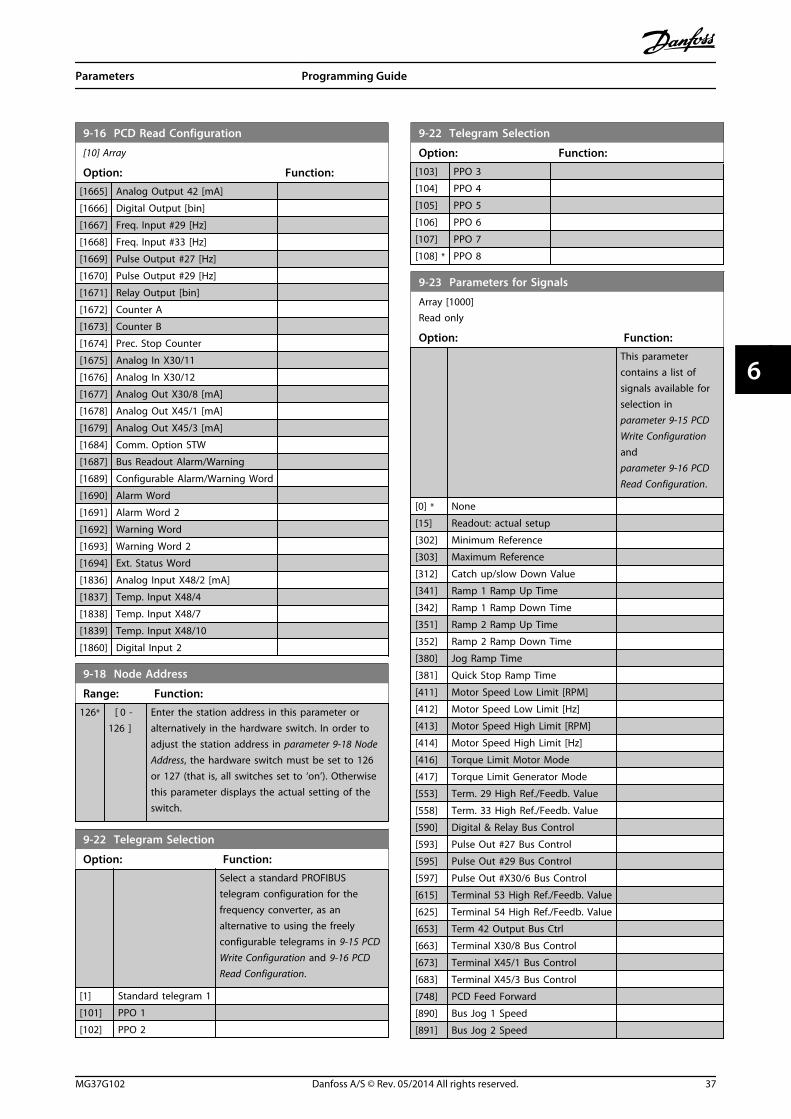
9-16 PCD Read Configuration
[10] Array
Option: Function:[1665] Analog Output 42 [mA]
[1666] Digital Output [bin]
[1667] Freq. Input #29 [Hz]
[1668] Freq. Input #33 [Hz]
[1669] Pulse Output #27 [Hz]
[1670] Pulse Output #29 [Hz]
[1671] Relay Output [bin]
[1672] Counter A
[1673] Counter B
[1674] Prec. Stop Counter
[1675] Analog In X30/11
[1676] Analog In X30/12
[1677] Analog Out X30/8 [mA]
[1678] Analog Out X45/1 [mA]
[1679] Analog Out X45/3 [mA]
[1684] Comm. Option STW
[1687] Bus Readout Alarm/Warning
[1689] Configurable Alarm/Warning Word
[1690] Alarm Word
[1691] Alarm Word 2
[1692] Warning Word
[1693] Warning Word 2
[1694] Ext. Status Word
[1836] Analog Input X48/2 [mA]
[1837] Temp. Input X48/4
[1838] Temp. Input X48/7
[1839] Temp. Input X48/10
[1860] Digital Input 2
9-18 Node Address
Range: Function:126* [ 0 -
126 ]Enter the station address in this parameter oralternatively in the hardware switch. In order toadjust the station address in parameter 9-18 NodeAddress, the hardware switch must be set to 126or 127 (that is, all switches set to ‘on’). Otherwisethis parameter displays the actual setting of theswitch.
9-22 Telegram Selection
Option: Function:Select a standard PROFIBUStelegram configuration for thefrequency converter, as analternative to using the freelyconfigurable telegrams in 9-15 PCDWrite Configuration and 9-16 PCDRead Configuration.
[1] Standard telegram 1
[101] PPO 1
[102] PPO 2
9-22 Telegram Selection
Option: Function:[103] PPO 3
[104] PPO 4
[105] PPO 5
[106] PPO 6
[107] PPO 7
[108] * PPO 8
9-23 Parameters for Signals
Array [1000]Read only
Option: Function:This parametercontains a list ofsignals available forselection in parameter 9-15 PCDWrite Configurationand parameter 9-16 PCDRead Configuration.
[0] * None
[15] Readout: actual setup
[302] Minimum Reference
[303] Maximum Reference
[312] Catch up/slow Down Value
[341] Ramp 1 Ramp Up Time
[342] Ramp 1 Ramp Down Time
[351] Ramp 2 Ramp Up Time
[352] Ramp 2 Ramp Down Time
[380] Jog Ramp Time
[381] Quick Stop Ramp Time
[411] Motor Speed Low Limit [RPM]
[412] Motor Speed Low Limit [Hz]
[413] Motor Speed High Limit [RPM]
[414] Motor Speed High Limit [Hz]
[416] Torque Limit Motor Mode
[417] Torque Limit Generator Mode
[553] Term. 29 High Ref./Feedb. Value
[558] Term. 33 High Ref./Feedb. Value
[590] Digital & Relay Bus Control
[593] Pulse Out #27 Bus Control
[595] Pulse Out #29 Bus Control
[597] Pulse Out #X30/6 Bus Control
[615] Terminal 53 High Ref./Feedb. Value
[625] Terminal 54 High Ref./Feedb. Value
[653] Term 42 Output Bus Ctrl
[663] Terminal X30/8 Bus Control
[673] Terminal X45/1 Bus Control
[683] Terminal X45/3 Bus Control
[748] PCD Feed Forward
[890] Bus Jog 1 Speed
[891] Bus Jog 2 Speed
Parameters Programming Guide
MG37G102 Danfoss A/S © Rev. 05/2014 All rights reserved. 37
6 6

9-23 Parameters for Signals
Array [1000]Read only
Option: Function:[1472] Legacy Alarm Word
[1473] Legacy Warning Word
[1474] Leg. Ext. Status Word
[1500] Operating hours
[1501] Running Hours
[1502] kWh Counter
[1600] Control Word
[1601] Reference [Unit]
[1602] Reference %
[1603] Status Word
[1605] Main Actual Value [%]
[1609] Custom Readout
[1610] Power [kW]
[1611] Power [hp]
[1612] Motor Voltage
[1613] Frequency
[1614] Motor current
[1615] Frequency [%]
[1616] Torque [Nm]
[1617] Speed [RPM]
[1618] Motor Thermal
[1619] KTY sensor temperature
[1620] Motor Angle
[1621] Torque [%] High Res.
[1622] Torque [%]
[1623] Motor Shaft Power [kW]
[1624] Calibrated Stator Resistance
[1625] Torque [Nm] High
[1630] DC Link Voltage
[1632] Brake Energy /s
[1633] Brake Energy /2 min
[1634] Heatsink Temp.
[1635] Inverter Thermal
[1638] SL Controller State
[1639] Control Card Temp.
[1645] Motor Phase U Current
[1646] Motor Phase V Current
[1647] Motor Phase W Current
[1648] Speed Ref. After Ramp [RPM]
[1650] External Reference
[1651] Pulse Reference
[1652] Feedback[Unit]
[1653] Digi Pot Reference
[1657] Feedback [RPM]
[1660] Digital Input
[1661] Terminal 53 Switch Setting
[1662] Analog Input 53
[1663] Terminal 54 Switch Setting
[1664] Analog Input 54
[1665] Analog Output 42 [mA]
9-23 Parameters for Signals
Array [1000]Read only
Option: Function:[1666] Digital Output [bin]
[1667] Freq. Input #29 [Hz]
[1668] Freq. Input #33 [Hz]
[1669] Pulse Output #27 [Hz]
[1670] Pulse Output #29 [Hz]
[1671] Relay Output [bin]
[1672] Counter A
[1673] Counter B
[1674] Prec. Stop Counter
[1675] Analog In X30/11
[1676] Analog In X30/12
[1677] Analog Out X30/8 [mA]
[1678] Analog Out X45/1 [mA]
[1679] Analog Out X45/3 [mA]
[1680] Fieldbus CTW 1
[1682] Fieldbus REF 1
[1684] Comm. Option STW
[1685] FC Port CTW 1
[1686] FC Port REF 1
[1687] Bus Readout Alarm/Warning
[1689] Configurable Alarm/Warning Word
[1690] Alarm Word
[1691] Alarm Word 2
[1692] Warning Word
[1693] Warning Word 2
[1694] Ext. Status Word
[1836] Analog Input X48/2 [mA]
[1837] Temp. Input X48/4
[1838] Temp. Input X48/7
[1839] Temp. Input X48/10
[1860] Digital Input 2
[3310] Sync Factor Master
[3311] Sync Factor Slave
[3401] PCD 1 Write to MCO
[3402] PCD 2 Write to MCO
[3403] PCD 3 Write to MCO
[3404] PCD 4 Write to MCO
[3405] PCD 5 Write to MCO
[3406] PCD 6 Write to MCO
[3407] PCD 7 Write to MCO
[3408] PCD 8 Write to MCO
[3409] PCD 9 Write to MCO
[3410] PCD 10 Write to MCO
[3421] PCD 1 Read from MCO
[3422] PCD 2 Read from MCO
[3423] PCD 3 Read from MCO
[3424] PCD 4 Read from MCO
[3425] PCD 5 Read from MCO
[3426] PCD 6 Read from MCO
[3427] PCD 7 Read from MCO
Parameters Programming Guide
38 Danfoss A/S © Rev. 05/2014 All rights reserved. MG37G102
66

9-23 Parameters for Signals
Array [1000]Read only
Option: Function:[3428] PCD 8 Read from MCO
[3429] PCD 9 Read from MCO
[3430] PCD 10 Read from MCO
[3440] Digital Inputs
[3441] Digital Outputs
[3450] Actual Position
[3451] Commanded Position
[3452] Actual Master Position
[3453] Slave Index Position
[3454] Master Index Position
[3455] Curve Position
[3456] Track Error
[3457] Synchronizing Error
[3458] Actual Velocity
[3459] Actual Master Velocity
[3460] Synchronizing Status
[3461] Axis Status
[3462] Program Status
[3464] MCO 302 Status
[3465] MCO 302 Control
[3470] MCO Alarm Word 1
[3471] MCO Alarm Word 2
[4280] Safe Option Status
[4285] Active Safe Func.
9-27 Parameter Edit
Option: Function:Parameters can be edited via PROFIBUS, thestandard RS-485 interface, or the LCP.
[0] Disabled Disables editing via PROFIBUS.
[1] * Enabled Enables editing via PROFIBUS.
9-28 Process Control
Option: Function:Process control (setting of control word, speedreference, and process data) is possible via eitherPROFIBUS or standard fieldbus but not bothsimultaneously. Local control is always possiblevia the LCP. Control via process control is possiblevia either terminals or fieldbus depending on thesettings in parameter 8-50 Coasting Select to parameter 8-56 Preset Reference Select.
[0] Disable Disables process control via PROFIBUS, andenables process control via standard fieldbus orPROFIBUS master class 2.
[1]*
Enablecyclicmaster
Enables process control via PROFIBUS master class1, and disables process control via standardfieldbus or PROFIBUS master class 2.
9-53 Profibus Warning Word
Range: Function:0* [0 - 65535 ] This parameter displays PROFIBUS communi-
cation warnings. Refer to the PROFIBUSOperating Instructions for further information.
Read only
Bit Meaning
0 Connection with DP-master is not OK.
1 Not used
2 FDL (fieldbus data link layer) is not OK.
3 Clear data command received.
4 Actual value is not updated.
5 Baudrate search
6 PROFIBUS ASIC is not transmitting.
7 Initialisation of PROFIBUS is not OK.
8 Frequency converter is tripped.
9 Internal CAN error
10 Wrong configuration data from PLC
11 Wrong ID sent by PLC.
12 Internal error occured
13 Not configured
14 Timeout active
15 Warning 34 active
Table 6.1 PROFIBUS Warning Word
9-63 Actual Baud Rate
Option: Function:This parameter displays the actualPROFIBUS baud rate. The PROFIBUSmaster automatically sets the baudrate.
[0] 9,6 kbit/s
[1] 19,2 kbit/s
[2] 93,75 kbit/s
[3] 187,5 kbit/s
[4] 500 kbit/s
[6] 1500 kbit/s
[7] 3000 kbit/s
[8] 6000 kbit/s
[9] 12000 kbit/s
[10] 31,25 kbit/s
[11] 45,45 kbit/s
[255] * No baudrate found
9-64 Device Identification
Range: Function:0* [0 - 0 ] This parameter displays the device identification.
Refer to the Operating Instructions for PROFIBUS, forfurther explanation.
Parameters Programming Guide
MG37G102 Danfoss A/S © Rev. 05/2014 All rights reserved. 39
6 6

9-65 Profile Number
Range: Function:0* [0 - 0 ] This parameter contains the profile identification.
Byte 1 contains the profile number and byte 2 theversion number of the profile.
NOTICEThis parameter is not visible via LCP.
9-70 Programming Set-up
Option: Function:Select the set-up to be edited.
[0] Factory setup Uses default data. This option can be usedas a data source to return the other set-upsto a known state.
[1] Set-up 1 Edits Set-up 1.
[2] Set-up 2 Edits Set-up 2.
[3] Set-up 3 Edits Set-up 3.
[4] Set-up 4 Edits Set-up 4.
[9] * Active Set-up Follows the active set-up selected in0-10 Active Set-up.
This parameter is unique for LCP and fieldbus. See0-11 Programming Set-up.
9-71 Profibus Save Data Values
Option: Function:Parameter values changed via PROFIBUS are notautomatically stored in non-volatile memory.Use this parameter to activate a function thatstores parameter values in the EEPROM non-volatile memory, so changed parameter valuesare retained at power-down.
[0] * Off Deactivates the non-volatile storage function.
[1] Store allsetups
Stores all parameter values for all set-ups in thenon-volatile memory. The selection returns to[0] Off when all parameter values have beenstored.
[2] Store allsetups
Stores all parameter values for all set-ups in thenon-volatile memory. The selection returns to[0] Off when all parameter values have beenstored.
9-72 ProfibusDriveReset
Option: Function:[0] * No action
[1] Power-onreset
Resets frequency converter upon power-up, asfor power-cycle.
[3] Commoptionreset
Resets the PROFIBUS option only, useful afterchanging certain settings in parameter group9-**, for example, parameter 9-18 Node Address.
9-72 ProfibusDriveReset
Option: Function:When reset, the frequency converterdisappears from the fieldbus, which may causea communication error from the master.
9-80 Defined Parameters (1)
Array [116]No LCP accessRead only
Range: Function:0* [0 - 9999 ] This parameter displays a list of all the defined
frequency converter parameters available forPROFIBUS.
9-81 Defined Parameters (2)
Array [116]No LCP accessRead only
Range: Function:0* [0 - 9999 ] This parameter displays a list of all the defined
frequency converter parameters available forPROFIBUS.
9-82 Defined Parameters (3)
Array [116]No LCP accessRead only
Range: Function:0* [0 - 9999 ] This parameter displays a list of all the defined
frequency converter parameters available forPROFIBUS.
9-83 Defined Parameters (4)
Array [116]No LCP accessRead only
Range: Function:0* [0 - 9999 ] This parameter displays a list of all the defined
frequency converter parameters available forPROFIBUS.
9-90 Changed Parameters (1)
Array [116]No LCP accessRead only
Range: Function:0* [0 - 9999 ] This parameter displays a list of all the
frequency converter parameters deviating fromdefault setting.
Parameters Programming Guide
40 Danfoss A/S © Rev. 05/2014 All rights reserved. MG37G102
66

9-91 Changed Parameters (2)
Array [116]No LCP accessRead only
Range: Function:0* [0 - 9999 ] This parameter displays a list of all the
frequency converter parameters deviating fromdefault setting.
9-92 Changed Parameters (3)
Array [116]No LCP accessRead only
Range: Function:0* [0 - 9999 ] This parameter displays a list of all the
frequency converter parameters deviating fromdefault setting.
9-94 Changed Parameters (5)
Array [116]No LCP AddressRead only
Range: Function:0* [0 - 9999 ] This parameter displays a list of all the
frequency converter parameters deviating fromdefault setting.
16-84 Comm. Option STW
Range: Function:0* [0 - 65535 ] View the extended fieldbus comm. option
status word.For more information, refer to the relevantfieldbus manual.
16-90 Alarm Word
Range: Function:0* [0 - 4294967295 ] View the alarm word sent via the serial
communication port in hex code.
16-92 Warning Word
Range: Function:0* [0 - 4294967295 ] View the warning word sent via the serial
communication port in hex code.
Parameters Programming Guide
MG37G102 Danfoss A/S © Rev. 05/2014 All rights reserved. 41
6 6

6.3 PROFIBUS-specific Parameter List
Parameter Default value Range Conversion index Data type
8-01 Control Site [0] Dig. & ctrl. word [0-2] - Uint8
Parameter 8-02 Control Word Source [0] FC RS485 [0-4] - Uint8
Parameter 8-03 Control Word Timeout Time 1 0.1-18000 -1 Uint32
Parameter 8-04 Control Word Timeout Function [0] Off [0-10] - Uint8
8-05 End-of-Timeout Function [0] Hold set-up [0-1] - Uint8
Parameter 8-06 Reset Control Word Timeout [0] Do not reset [0-1] - Uint8
Parameter 8-07 Diagnosis Trigger [0] Disable [0-3] - Uint8
Parameter 8-10 Control Word Profile [0] FC profile [0-x] - Uint8
8-50 Coasting Select *[3] Logic OR [0-3] - Uint8
Parameter 8-51 Quick Stop Select *[3] Logic OR [0-3] - Uint8
8-52 DC Brake Select *[3] Logic OR [0-3] - Uint8
8-53 Start Select *[3] Logic OR [0-3] - Uint8
Parameter 8-54 Reversing Select *[3] Logic OR [0-3] - Uint8
8-55 Set-up Select *[3] Logic OR [0-3] - Uint8
8-56 Preset Reference Select *[3] Logic OR [0-3] - Uint8
8-90 Bus Jog 1 Speed 100 rpm 0-par. 4-13 67 Uint16
8-91 Bus Jog 2 Speed 200 rpm 0-par. 4-13 67 Uint16
Parameter 9-15 PCD Write Configuration - - - Uint16
Parameter 9-16 PCD Read Configuration - - - Uint16
9-18 Node Address 126 1-126 0 Uint8
9-22 Telegram Selection - [0-108] - Uint8
Parameter 9-23 Parameters for Signals - 0-573 - Uint16
9-27 Parameter Edit [1] Enabled [0-1] - Uint16
9-28 Process Control [1] Enable cyclic master [0-1] - Uint16
9-44 Fault Message Counter 0 [0-8] 0 Uint16
9-45 Fault Code 0 - - Uint16
9-47 Fault Number 0 - - Uint16
9-52 Fault Situation Counter 0 0-1000 0 Uint16
9-53 Profibus Warning Word 0 16 bits 0 V2
9-63 Actual Baud Rate [255] No baud rate found 9.6-12000 kbits 0 Uint8
Parameter 9-64 Device Identification 0 [0-10] 0 Uint16
9-65 Profile Number 0 8 bits 0 Uint8
9-70 Edit Set-up [9] Active set-up [0-9] - Uint8
9-71 Profibus Save Data Values [0] Off [0-2] - Uint8
9-72 ProfibusDriveReset [0] No action [0-2] - Uint8
9-80 Defined Parameters (1) - 0-115 0 Uint16
9-81 Defined Parameters (2) 0-115 0 Uint16
9-82 Defined Parameters (3) - 0-115 0 Uint16
9-83 Defined Parameters (4) - 0-115 0 Uint16
9-90 Changed Parameters (1) - 0-115 0 Uint16
9-91 Changed Parameters (2) - 0-115 0 Uint16
9-92 Changed Parameters (3) - 0-115 0 Uint16
9-93 Changed Parameters (4) - 0-115 0 Uint16
16-84 Comm. Option STW 0 0-FFFF 0 V2
16-90 Alarm Word 0 0-FFFF 0 Uint32
16-92 Warning Word 0 0-FFFF 0 Uint32
Table 6.2 PROFIBUS-specific Parameter List
Refer to the relevant operating instructions for a comprehensive parameter list.
Parameters Programming Guide
42 Danfoss A/S © Rev. 05/2014 All rights reserved. MG37G102
66
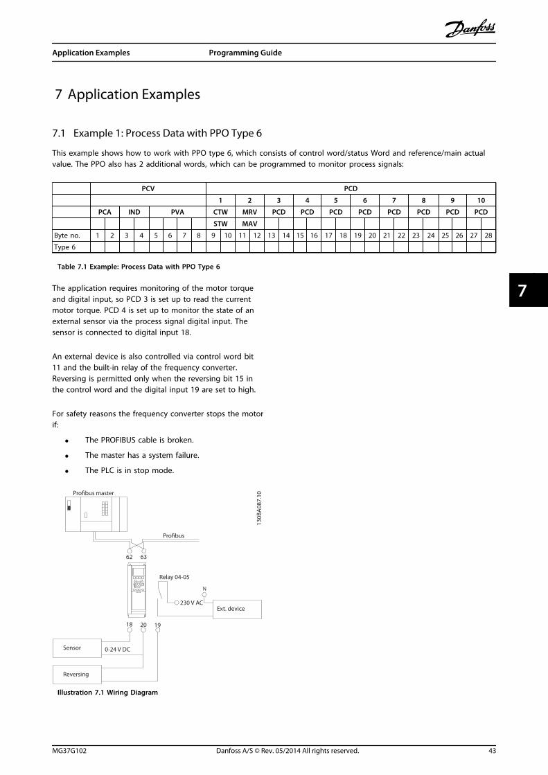
7 Application Examples
7.1 Example 1: Process Data with PPO Type 6
This example shows how to work with PPO type 6, which consists of control word/status Word and reference/main actualvalue. The PPO also has 2 additional words, which can be programmed to monitor process signals:
PCV PCD
1 2 3 4 5 6 7 8 9 10
PCA IND PVA CTW MRV PCD PCD PCD PCD PCD PCD PCD PCD
STW MAV
Byte no. 1 2 3 4 5 6 7 8 9 10 11 12 13 14 15 16 17 18 19 20 21 22 23 24 25 26 27 28
Type 6
Table 7.1 Example: Process Data with PPO Type 6
The application requires monitoring of the motor torqueand digital input, so PCD 3 is set up to read the currentmotor torque. PCD 4 is set up to monitor the state of anexternal sensor via the process signal digital input. Thesensor is connected to digital input 18.
An external device is also controlled via control word bit11 and the built-in relay of the frequency converter.Reversing is permitted only when the reversing bit 15 inthe control word and the digital input 19 are set to high.
For safety reasons the frequency converter stops the motorif:
• The PROFIBUS cable is broken.
• The master has a system failure.
• The PLC is in stop mode.
Pro�bus master
Pro�bus
Relay 04-05
230 V ACExt. device
Sensor
Reversing
6362
18 20 19
0-24 V DC
130B
A08
7.10
Illustration 7.1 Wiring Diagram
Application Examples Programming Guide
MG37G102 Danfoss A/S © Rev. 05/2014 All rights reserved. 43
7 7

Program the frequency converter as in Table 7.2:
Parameter Setting
4-10 Motor Speed Direction [2] Both directions
5-10 Terminal 18 Digital Input [0] No operation
5-11 Terminal 19 Digital Input [10] Reversing
5-40 Function Relay [36/37] Control word bit 11/12
parameter 8-03 Control Word Timeout Time 1 s
parameter 8-04 Control Word Timeout Function [2] Stop
parameter 8-10 Control Word Profile [0] FC Profile
8-50 Coasting Select [1] Bus
parameter 8-51 Quick Stop Select [1] Bus
8-52 DC Brake Select [1] Bus
8-53 Start Select [1] Bus
parameter 8-54 Reversing Select [2] Logic AND
8-55 Set-up Select [1] Bus
8-56 Preset Reference Select [1] Bus
parameter 9-16 PCD Read Configuration [2] Sub index 16-16 Torque [Nm][3] Sub index 16-60 Digital Input
9-18 Node Address Set the address
Table 7.2 Parameter Settings
7.2 Example 2: Control Word Telegram using PPO Type
This example shows how the control word telegram relates to the PLC and the frequency converter, using FC control profile.
The control word telegram is sent from the PLC to the frequency converter. PPO Type 3 is used in the example todemonstrate the full range of modules. All the values shown are arbitrary, and are provided for demonstration purposesonly.
Table 7.3 indicates the bits contained within the control word, and how they are presented as process data in PPO type 3for this example.
PCV PCD
1 2 3 4 5 6
PCA IND PVA CTW MRV PCD PCD PCD PCD
04 7C 20 00
PQW 256 258 260 262 264 266 268 270 272 274
master slave CTW MRV
Bit no. 15 14 13 12 11 10 9 8 7 6 5 4 3 2 1 0
0 0 0 0 0 1 0 0 0 1 1 1 1 1 0 0
0 4 7 C
Table 7.3 Example: Control Word Telegram using PPO Type
Table 7.4 indicates the bit functions and corresponding bit values which are active for this example.
Application Examples Programming Guide
44 Danfoss A/S © Rev. 05/2014 All rights reserved. MG37G102
77

Bit Bit value=0 Bit value=1 Bit value
00 Reference value External selection lsb 0
C01 Reference value External selection msb 0
02 DC brake Ramp 1
03 Coasting Enable 1
04 Quick stop Ramp 1
705 Freeze output Ramp enable 1
06 Ramp stop Start 1
07 No function Reset 0
08 No function Jog 0
409 Ramp 1 Ramp 2 0
10 Data not valid Valid 1
11 No function Relay 01 active 0
12 No function Relay 02 active 0
013 Parameter set-up Selection lsb 0
14 Parameter set-up Selection msb 0
15 No function Reversing 0
Function active
Function inactive
Table 7.4 Active Bit Functions for Control Word Telegram using PPO Type
7.3 Example 3: Status Word Telegram using PPO Type
This example shows how the control word telegram relates to the PLC and the frequency converter, using FC control profile.
The control word telegram is sent from the PLC to the frequency converter. PPO type 3 is used in the example todemonstrate the full range of modules. All the values shown are arbitrary, and are provided for demonstration purposesonly.
Table 7.5 indicates the bits contained within the status word, and how they are presented as process data in PPO type 3 forthis example.
PCV PCD
1 2 3 4 5 6
PCA IND PVA CTW MRV PCD PCD PCD PCD
0F 07 20 00
PIW: 256 258 260 262 264 266 268 270 272 274
master slave STW MAV
Bit no.: 15 14 13 12 11 10 9 8 7 6 5 4 3 2 1 0
0 0 0 0 0 1 0 0 0 1 1 1 1 1 0 0
0 4 7 C
Table 7.5 Example: Status Word Telegram using PPO Type
Table 7.6 indicates the bit functions, and the corresponding bit values which are active for this example.
Application Examples Programming Guide
MG37G102 Danfoss A/S © Rev. 05/2014 All rights reserved. 45
7 7

Bit Bit value=0 Bit value=1 Bit value
00 Control not ready Control ready 1
701 Drive not ready Drive ready 1
02 Coasting Enable 1
03 No error Trip 0
04 No error Error (no trip) 0
005 Reserved - 0
06 No error Triplock 0
07 No warning Warning 0
08 Speed reference Speed = reference 1
F09 Local operation Bus control 1
10 Outside frequency range Within frequency range 1
11 No operation In operation 1
12 Drive OK Stopped, autostart 0
013 Voltage OK Voltage exceeded 0
14 Torque OK Torque exceeded 0
15 Timers OK Timers exceeded 0
Function active
Function inactive
Table 7.6 Active Bit Functions for Status Word Telegram using PPO Type
7.4 Example 4: PLC Programming
In this example PPO type 6 is placed in the input/output address, see Illustration 7.2 and Table 7.7.
Illustration 7.2 FC 302 and PPO Type 6 PCD
Inputaddress
256-257 258-259 260-261 262-263 Outputaddress
256-257 258-259 260-261 262-263
Set-up Statusword
MAV Motortorque
Digitalinput
Set-up Controlword
Reference Not used Not used
Table 7.7 Input/Output Address Set-up
This network sends a start command (047C hex) and areference (2000 hex) of 50% to the frequency converter.
Illustration 7.3 Network Sends a Start Command and aReference of 50% to the Frequency Converter.
Application Examples Programming Guide
46 Danfoss A/S © Rev. 05/2014 All rights reserved. MG37G102
77

This network reads the motor torque from the frequencyconverter. A new reference is sent to the frequencyconverter because the motor torque (86.0%) is higher thanthe compared value.
Illustration 7.4 Network Reads the Motor Torque from theFrequency Converter
This network reads the status on the digital inputs fromthe frequency converter. If digital input 18 is On, it stopsthe frequency converter.
Illustration 7.5 Network Reads the Status on the Digital Inputsfrom the Frequency Converter
This network reverses the motor when digital input 19 isON, because parameter 8-54 Reversing Select isprogrammed to Logic AND.
Illustration 7.6 Network Reverses the Motor When DigitalInput 19 is ON
This network activates relay 02.
130BA110.10
Illustration 7.7 Network Activates Relay 02
Application Examples Programming Guide
MG37G102 Danfoss A/S © Rev. 05/2014 All rights reserved. 47
7 7

8 Troubleshooting
8.1 Diagnosis
PROFIBUS-DP provides a flexible way of performingdiagnosis of slave units, based on diagnosis messages.
During normal cyclical data exchange:
1. The slave sets a diagnosis bit, which requests themaster to send a diagnosis message during thenext scan cycle, instead of the normal dataexchange.
2. The slave answers the master with a diagnosismessage consisting of standard diagnosisinformation, 6 bytes, and possibly extended,vendor specific, diagnosis information. Thestandard diagnosis messages cover a limitedrange of general diagnosis possibilities, whereasthe extended diagnosis function offers detailedmessaging specific to the frequency converter.
See chapter 8.3 Warnings and Alarms for the extendeddiagnosis messages for the frequency converter.A master or a network analysing tool is able to translatethese diagnosis words into real text messages using theGSD-file.
NOTICEDP V1 diagnosis is supported for PROFIBUS SW version2.X and later versions. The default setting of thePROFIBUS option is DP V1 diagnosis.When DP V0 diagnosis is required, change the settingunder DP slave Properties.
8.2 No Response to Control Signals
Check that:
1. The control word is valid.When bit 10=0 in the control word, the frequencyconverter does not accept the control word. Thedefault setting is bit 10=1. Set bit 10=1 via thePLC.
2. Relationship between bits in the control wordand the terminal I/Os is correct.Check the logical relationship in the frequencyconverter. Set the logic to bit 3=1 and digitalinput=1 to achieve a successful start.
Select the FC control mode, digital input and/or serialcommunication, using 8-50 Coasting Select to 8-56 PresetReference Select.
Selecting control mode for 8-50 Coasting Select, parameter 8-51 Quick Stop Select, and 8-52 DC BrakeSelect:If [0] Digital input is selected, the terminals control thecoast and DC brake functions.
NOTICECoasting, Quick Stop, and DC Brake functions are activefor logic 0.
Terminal Bit 02/03/04 Function
0 0 Coast/DC brake/Q-Stop
0 1 Coast/DC brake/Q-Stop
1 0 No Coast/DC brake/Q-Stop
1 1 No Coast/DC brake/Q-Stop
Table 8.1 [0] Digital input
If [1] Serial communication is selected, commands areactivated only when given via serial communication.
Terminal Bit 02/03/04 Function
0 0 Coast/DC brake/Q-Stop
0 1 No Coast/DC brake/Q-Stop
1 0 Coast/DC brake/Q-Stop
1 1 No Coast/DC brake/Q-Stop
Table 8.2 [1] Serial communication
If [2] Logic AND is selected, activate both signals to performthe function.
Terminal Bit 02/03/04 Function
0 0 Coast/DC brake/Q-Stop
0 1 No Coast/DC brake/Q-Stop
1 0 No Coast/DC brake/Q-Stop
1 1 No Coast/DC brake/Q-Stop
Table 8.3 [2] Logic AND
If [3] Logic OR is selected, activation of 1 signal activatesthe function.
Terminal Bit 02/03/04 Function
0 0 Coast/DC brake/Q-Stop
0 1 Coast/DC brake/Q-Stop
1 0 Coast/DC brake/Q-Stop
1 1 No Coast/DC brake/Q-Stop
Table 8.4 [3] Logic OR
Troubleshooting Programming Guide
48 Danfoss A/S © Rev. 05/2014 All rights reserved. MG37G102
88
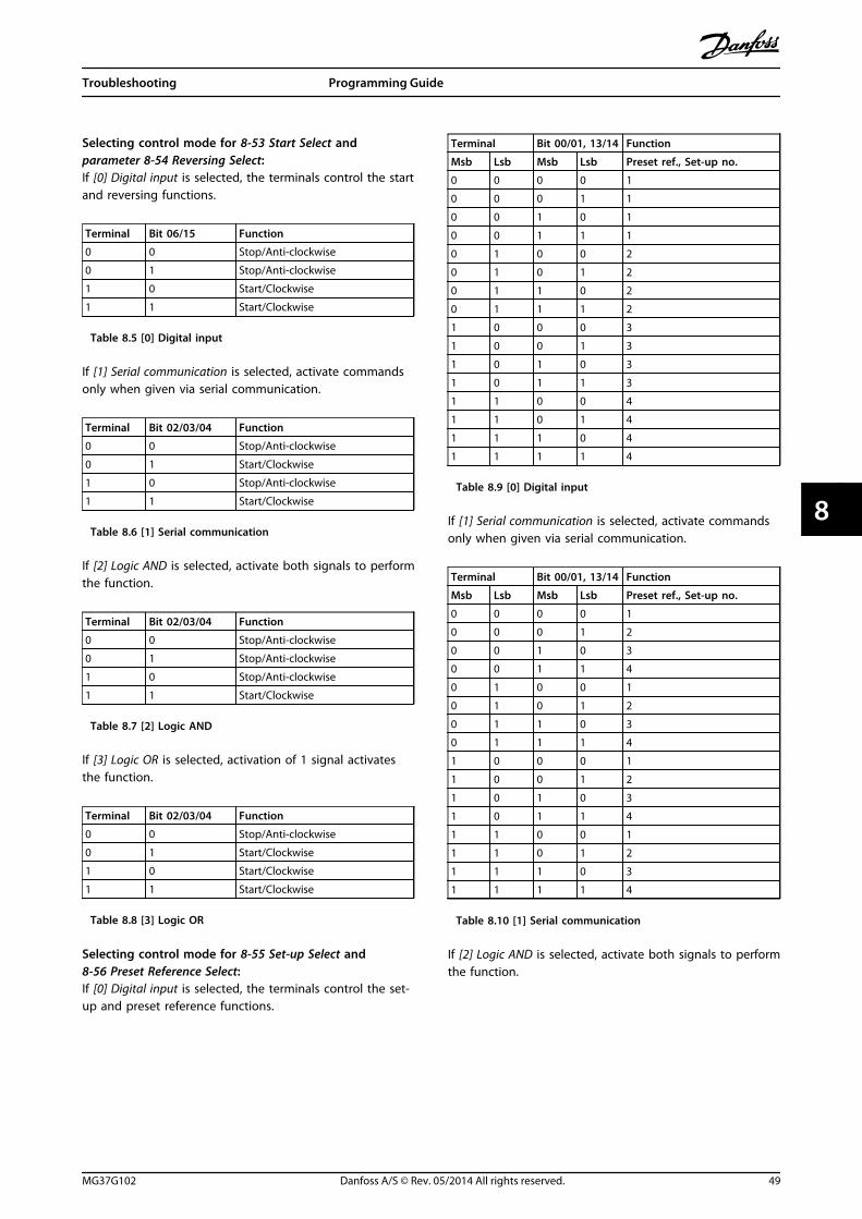
Selecting control mode for 8-53 Start Select and parameter 8-54 Reversing Select:If [0] Digital input is selected, the terminals control the startand reversing functions.
Terminal Bit 06/15 Function
0 0 Stop/Anti-clockwise
0 1 Stop/Anti-clockwise
1 0 Start/Clockwise
1 1 Start/Clockwise
Table 8.5 [0] Digital input
If [1] Serial communication is selected, activate commandsonly when given via serial communication.
Terminal Bit 02/03/04 Function
0 0 Stop/Anti-clockwise
0 1 Start/Clockwise
1 0 Stop/Anti-clockwise
1 1 Start/Clockwise
Table 8.6 [1] Serial communication
If [2] Logic AND is selected, activate both signals to performthe function.
Terminal Bit 02/03/04 Function
0 0 Stop/Anti-clockwise
0 1 Stop/Anti-clockwise
1 0 Stop/Anti-clockwise
1 1 Start/Clockwise
Table 8.7 [2] Logic AND
If [3] Logic OR is selected, activation of 1 signal activatesthe function.
Terminal Bit 02/03/04 Function
0 0 Stop/Anti-clockwise
0 1 Start/Clockwise
1 0 Start/Clockwise
1 1 Start/Clockwise
Table 8.8 [3] Logic OR
Selecting control mode for 8-55 Set-up Select and8-56 Preset Reference Select:If [0] Digital input is selected, the terminals control the set-up and preset reference functions.
Terminal Bit 00/01, 13/14 Function
Msb Lsb Msb Lsb Preset ref., Set-up no.
0 0 0 0 1
0 0 0 1 1
0 0 1 0 1
0 0 1 1 1
0 1 0 0 2
0 1 0 1 2
0 1 1 0 2
0 1 1 1 2
1 0 0 0 3
1 0 0 1 3
1 0 1 0 3
1 0 1 1 3
1 1 0 0 4
1 1 0 1 4
1 1 1 0 4
1 1 1 1 4
Table 8.9 [0] Digital input
If [1] Serial communication is selected, activate commandsonly when given via serial communication.
Terminal Bit 00/01, 13/14 Function
Msb Lsb Msb Lsb Preset ref., Set-up no.
0 0 0 0 1
0 0 0 1 2
0 0 1 0 3
0 0 1 1 4
0 1 0 0 1
0 1 0 1 2
0 1 1 0 3
0 1 1 1 4
1 0 0 0 1
1 0 0 1 2
1 0 1 0 3
1 0 1 1 4
1 1 0 0 1
1 1 0 1 2
1 1 1 0 3
1 1 1 1 4
Table 8.10 [1] Serial communication
If [2] Logic AND is selected, activate both signals to performthe function.
Troubleshooting Programming Guide
MG37G102 Danfoss A/S © Rev. 05/2014 All rights reserved. 49
8 8

Terminal Bit 00/01, 13/14 Function
Msb Lsb Msb Lsb Preset ref., Set-up no.
0 0 0 0 1
0 0 0 1 1
0 0 1 0 1
0 0 1 1 1
0 1 0 0 1
0 1 0 1 2
0 1 1 0 1
0 1 1 1 2
1 0 0 0 1
1 0 0 1 1
1 0 1 0 3
1 0 1 1 3
1 1 0 0 1
1 1 0 1 2
1 1 1 0 3
1 1 1 1 4
Table 8.11 [2] Logic AND
If [3] Logic OR is selected, activation of one signal activatesthe function.
Terminal Bit 00/01, 13/14 Function
Msb Lsb Msb Lsb Preset ref., Set-up no.
0 0 0 0 1
0 0 0 1 2
0 0 1 0 3
0 0 1 1 4
0 1 0 0 2
0 1 0 1 2
0 1 1 0 4
0 1 1 1 4
1 0 0 0 3
1 0 0 1 4
1 0 1 0 3
1 0 1 1 4
1 1 0 0 4
1 1 0 1 4
1 1 1 0 4
Table 8.12 [3] Logic OR
8.3 Warnings and Alarms
NOTICERefer to the relevant operating instructions for an overview of warning and alarm types and for the full list of warningsand alarms.
Alarm word, warning word, and PROFIBUS warning word are shown on the frequency converter display in hex format. Whenthere is more than 1 warning or alarm, the sum of all warnings or alarms is shown. Alarm word, warning word, andPROFIBUS warning word can also be displayed using the serial bus in 16-90 Alarm Word, 16-92 Warning Word, and9-53 Profibus Warning Word.
Troubleshooting Programming Guide
50 Danfoss A/S © Rev. 05/2014 All rights reserved. MG37G102
88

Bit (hex) Dec Unitdiagnose bit
Alarm word (16-90 Alarm Word) Alarm word 2 Alarm no.
00000001 1 48 Brake check ServiceTrip, Read/Write 28
00000002 2 49 Power card over temperature ServiceTrip, (reserved) 29
00000004 4 50 Earth fault ServiceTrip, Typecode/Sparepart
14
00000008 8 51 Control card over temperature ServiceTrip, (reserved) 65
00000010 16 52 Control word timeout ServiceTrip, (reserved) 18
00000020 32 53 Over current 13
00000040 64 54 Torque limit 12
00000080 128 55 Motor thermistor over temp. 11
00000100 256 40 Motor ETR over temperature 10
00000200 512 41 Inverter overloaded 9
00000400 1024 42 DC link under-voltage 8
00000800 2048 43 DC link over-voltage 7
00001000 4096 44 Short circuit 16
00002000 8192 45 Inrush fault 33
00004000 16384 46 Mains phase loss 4
00008000 32768 47 AMA not OK 50
00010000 65536 32 Live zero error 2
00020000 131072 33 Internal fault KTY error 38
00040000 262144 34 Brake overload Fans error 26
00080000 524288 35 Motor phase U is missing ECB error 30
00100000 1048576 36 Motor phase V is missing 31
00200000 2097152 37 Motor phase W is missing 32
00400000 4194304 38 Fieldbus comm. fault 34
00800000 8388608 39 24 V supply fault 47
01000000 16777216 24 Mains failure 36
02000000 33554432 25 1.8 V supply fault 48
04000000 67108864 26 Brake resistor short circuit 25
08000000 134217728 27 Brake chopper fault 27
10000000 268435456 28 Option change 67
20000000 536870912 29 Drive initialisation 80
40000000 1073741824 30 Safe stop PTC 1 Safe Stop (A71) 68
80000000 2147483648 31 Mechanical brake low Dangerous Failure (A72) 63
Table 8.13 16-90 Alarm Word
Troubleshooting Programming Guide
MG37G102 Danfoss A/S © Rev. 05/2014 All rights reserved. 51
8 8
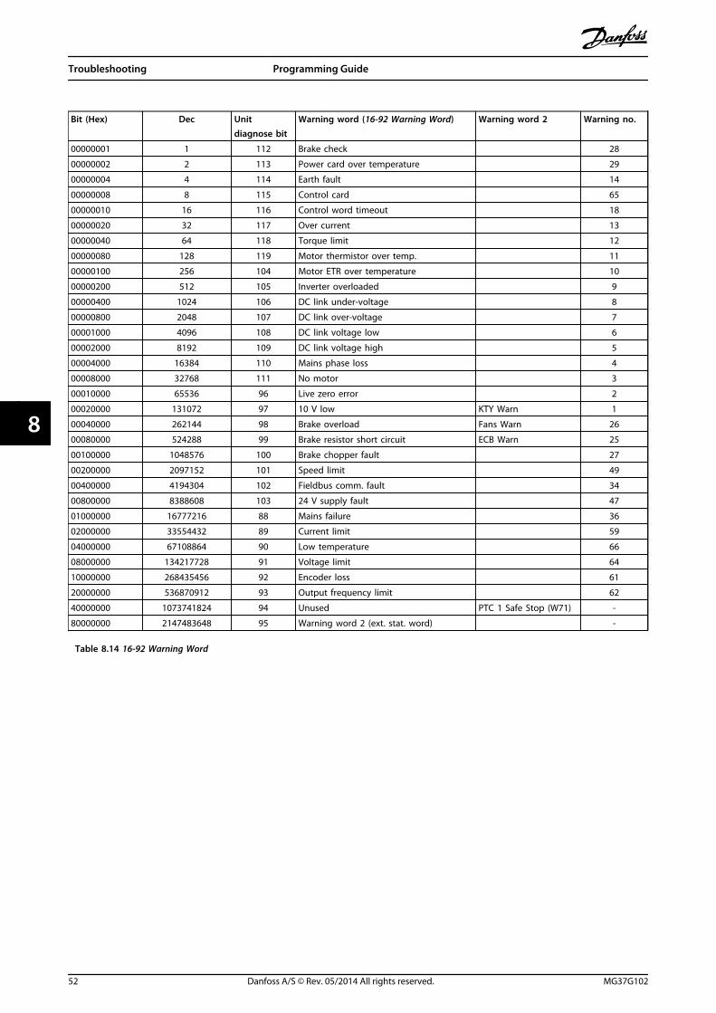
Bit (Hex) Dec Unitdiagnose bit
Warning word (16-92 Warning Word) Warning word 2 Warning no.
00000001 1 112 Brake check 28
00000002 2 113 Power card over temperature 29
00000004 4 114 Earth fault 14
00000008 8 115 Control card 65
00000010 16 116 Control word timeout 18
00000020 32 117 Over current 13
00000040 64 118 Torque limit 12
00000080 128 119 Motor thermistor over temp. 11
00000100 256 104 Motor ETR over temperature 10
00000200 512 105 Inverter overloaded 9
00000400 1024 106 DC link under-voltage 8
00000800 2048 107 DC link over-voltage 7
00001000 4096 108 DC link voltage low 6
00002000 8192 109 DC link voltage high 5
00004000 16384 110 Mains phase loss 4
00008000 32768 111 No motor 3
00010000 65536 96 Live zero error 2
00020000 131072 97 10 V low KTY Warn 1
00040000 262144 98 Brake overload Fans Warn 26
00080000 524288 99 Brake resistor short circuit ECB Warn 25
00100000 1048576 100 Brake chopper fault 27
00200000 2097152 101 Speed limit 49
00400000 4194304 102 Fieldbus comm. fault 34
00800000 8388608 103 24 V supply fault 47
01000000 16777216 88 Mains failure 36
02000000 33554432 89 Current limit 59
04000000 67108864 90 Low temperature 66
08000000 134217728 91 Voltage limit 64
10000000 268435456 92 Encoder loss 61
20000000 536870912 93 Output frequency limit 62
40000000 1073741824 94 Unused PTC 1 Safe Stop (W71) -
80000000 2147483648 95 Warning word 2 (ext. stat. word) -
Table 8.14 16-92 Warning Word
Troubleshooting Programming Guide
52 Danfoss A/S © Rev. 05/2014 All rights reserved. MG37G102
88

Bit Hex Dec Extended status word(16-94 Ext. Status Word)
0 00000001 1 Ramping
1 00000002 2 AMA running
2 00000004 4 Start CW/CCW
3 00000008 8 Slow down
4 00000010 16 Catch up
5 00000020 32 Feedback high
6 00000040 64 Feedback low
7 00000080 128 Output current high
8 00000100 256 Output current low
9 00000200 512 Output freq hgh
10 00000400 1024 Output freq low
11 00000800 2048 Brake check OK
12 00001000 4096 Braking max
13 00002000 8192 Braking
14 00004000 16384 Out of speed range
15 00008000 32768 OVC active
16 00010000 65536 AC brake
17 00020000 131072 Password timelock
18 00040000 262144 Password protection
19 00080000 524288
20 00100000 1048576
21 00200000 2097152
22 00400000 4194304 Unused
23 00800000 8388608 Unused
24 01000000 16777216 Unused
25 02000000 33554432 Unused
26 04000000 67108864 Unused
27 08000000 134217728 Unused
28 10000000 268435456 Unused
29 20000000 536870912 Unused
30 40000000 1073741824 Unused
31 80000000 2147483648 Unused
Table 8.15 Extended Status Word
Bit (Hex) Unitdiagnosebit
PROFIBUS warning word(9-53 Profibus Warning Word)
00000001 160 Connection with DP-master is not OK.
00000002 161 Unused
00000004 162 FDL (fieldbus data link layer) is not OK.
00000008 163 Clear data command received.
00000010 164 Actual value is not updated.
00000020 165 Baudrate search
00000040 166 PROFIBUS ASIC is not transmitting
00000080 167 Initialising of PROFIBUS is not OK.
00000100 152 Drive is tripped.
00000200 153 Internal CAN error
00000400 154 Wrong configuration data from PLC
00000800 155 Wrong ID sent by PLC.
00001000 156 Internal error occurred.
00002000 157 Not configured
00004000 158 Timeout active
00008000 159 Warning 34 active
Table 8.16 9-53 Profibus Warning Word
Bit (Hex) Comm. option STW (16-84 Comm. Option STW)
00000001 Parameterisation OK
00000002 Configuration OK
00000004 Clear mode active
00000008 Baudrate search
00000010 Waiting for parameterisation
00000020 Waiting for configuration
00000040 In data exchange
00000080 Not used
00000100 Not used
00000200 Not used
00000400 Not used
00000800 MCL2/1 connected
00001000 MCL2/2 connected
00002000 MCL2/3 connected
00004000 Data transport active
00008000 Unused
Table 8.17 16-84 Comm. Option STW
NOTICE16-84 Comm. Option STW is not part of extendeddiagnosis.
Read out the alarm words, warning words and extendedstatus words via serial bus or optional fieldbus fordiagnosis.
8.4 Fault Messages via DP Diagnosis
The standard DP function features an on-line diagnosis,which is active during DP initialisation as well as dataexchange mode.
Troubleshooting Programming Guide
MG37G102 Danfoss A/S © Rev. 05/2014 All rights reserved. 53
8 8

8.5 Extended Diagnosis
Receive the extended diagnosis function, alarm andwarning information from the frequency converter. Thesetting of parameter 8-07 Diagnosis Trigger determineswhich frequency converter events trigger the extendeddiagnosis function:
• When parameter 8-07 Diagnosis Trigger is set to[0] Disable, no extended diagnosis data are sentregardless of whether they appear in thefrequency converter.
• When parameter 8-07 Diagnosis Trigger is set to[1] Alarms, extended diagnosis data are sentwhen one or more alarms arrive in the alarm16-90 Alarm Word or 9-53 Profibus Warning Word.
When parameter 8-06 Reset Control Word Timeout is set to[2] Alarms/Warnings, extended diagnosis data are sent if 1or more alarms/warnings arrive in the alarm 16-90 AlarmWord or 9-53 Profibus Warning Word, or in the warning16-92 Warning Word.
The extended diagnosis sequence is as follows:If an alarm or warning appears, the frequency converterindicates that to the master by sending a high prioritymessage via the output data telegram. This causes themaster to send a request for extended diagnosisinformation to the frequency converter, to which thefrequency converter replies. When the alarm or warningdisappears, the frequency converter again indicates that tothe master, and on the following request from the master,return a standard DP diagnosis frame (6 bytes).
Byte Bit no. Name
0 to 5 - Standard DP diagnosis data
6 - PDU length
7 0-7 Status type =0x81
8 8-15 Slot=0
9 16-23 Status information
10 24-31 16-90 Alarm Word
11 32-39 16-90 Alarm Word
12 40-47 16-90 Alarm Word
13 48-55 16-90 Alarm Word
14 56-63 Reserved for future use
15 64-71 Reserved for future use
16 72-79 Reserved for future use
17 80-87 Reserved for future use
18 88-95 16-92 Warning Word
19 96-103 16-92 Warning Word
20 104-111 16-92 Warning Word
21 112-119 16-92 Warning Word
22 120-127 Reserved for future use
23 128-135 Reserved for future use
24 136-143 Reserved for future use
25 144-151 Reserved for future use
26 152-159 9-53 Profibus Warning Word
27 160-167 9-53 Profibus Warning Word
28 168-175 Reserved for future use
29 176-183 Reserved for future use
30 184-191 Reserved for future use
31 192-199 Reserved for future use
Table 8.18 Content of the Extended Diagnosis Frame
Troubleshooting Programming Guide
54 Danfoss A/S © Rev. 05/2014 All rights reserved. MG37G102
88
Index
AAbbreviations........................................................................................... 5
Additional resources.............................................................................. 3
Alarm word............................................................................................. 50
Alarms....................................................................................................... 50
Approvals............................................................................................. 0
CCertifications....................................................................................... 0
Complete Description......................................................................... 27
Configuration......................................................................................... 33
Control profile........................................................................................ 16
Control word.......................................................................................... 16
Conventions.............................................................................................. 5
CTW........................................................................................................... 16
DData store................................................................................................ 23
Data types supported......................................................................... 32
Discharge time......................................................................................... 6
EExtended diagnosis............................................................................. 54
FFault messages via DP diagnosis.................................................... 53
FC control modeDigital input terminals................................................................... 16
Field PCD Normalization.................................................................... 27
FREEZE/UNFREEZE............................................................................... 22
Frequency converter parameters................................................... 11
GGSD File...................................................................................................... 9
HHigh voltage............................................................................................. 6
IID extension............................................................................................ 27
Identifier ID............................................................................................. 27
LLeakage current....................................................................................... 7
LEDs........................................................................................................... 11
Load sharing............................................................................................. 6
Lower limit.............................................................................................. 27
MMCT 10........................................................................................................ 4
MRV............................................................................................................ 30
NName......................................................................................................... 27
Number of array elements................................................................ 27
PParameter access.................................................................................. 23
PCA handling......................................................................................... 28
PCA parameter characteristic........................................................... 28
PCD............................................................................................................ 30
PCD reference parameter.................................................................. 27
PCV............................................................................................................. 30
PCV parameter access......................................................................... 28
PPO types................................................................................................ 13
Process control data............................................................................ 14
Process control operation................................................................. 16
Process data............................................................................................ 14
Process status data............................................................................... 14
PROFIBUS address.................................................................................. 8
PROFIBUS DP-V1Acyclical parameter channel........................................................ 25Attribute description...................................................................... 27Data exchange.................................................................................. 24Error codes.......................................................................................... 28Master class 1 connection............................................................. 24Master class 2 connection............................................................. 24Parameter access............................................................................. 24Read/write services......................................................................... 25Request ID.......................................................................................... 26Request reference............................................................................ 26Request/response attributes....................................................... 26Response ID....................................................................................... 26Supported data types..................................................................... 28Value..................................................................................................... 28
PROFIdrive profile (CTW)................................................................... 16
PROFIdrive state transition diagram.............................................. 19
QQualified personnel................................................................................ 6
RRC content............................................................................................... 29
Read/write in double word format................................................ 23
Reference handling.............................................................................. 15
Index Programming Guide
MG37G102 Danfoss A/S © Rev. 05/2014 All rights reserved. 55

Request/response handling............................................................. 29
SSafety........................................................................................................... 7
Services overview................................................................................. 24
Size attribute.......................................................................................... 31
Status word............................................................................................. 18
Symbols...................................................................................................... 5
SYNC/UNSYNC....................................................................................... 22
TTermination switch................................................................................. 8
UUnintended start..................................................................................... 6
Upper limit.............................................................................................. 27
WWarning word........................................................................................ 50
Warnings.................................................................................................. 50
Index Programming Guide
56 Danfoss A/S © Rev. 05/2014 All rights reserved. MG37G102

Index Programming Guide
MG37G102 Danfoss A/S © Rev. 05/2014 All rights reserved. 57

www.danfoss.com/drives
Danfoss can accept no responsibility for possible errors in catalogues, brochures and other printed material. Danfoss reserves the right to alter its products without notice. This also applies toproducts already on order provided that such alterations can be made without subsequential changes being necessary in specifications already agreed. All trademarks in this material are propertyof the respective companies. Danfoss and the Danfoss logotype are trademarks of Danfoss A/S. All rights reserved.
Danfoss A/SUlsnaes 1DK-6300 Graastenwww.danfoss.com/drives
*MG37G102*130R0591 MG37G102 Rev. 05/2014