VLT 3000 Series - TecDriver 3000 SERIES INGLES.pdfVLT® 3000 Series Product Manual Software version:...
156
1 MG.30.A7.02 - VLT ® is a registered Danfoss trademark VLT ® 3000 Series Product Manual Software version: 3.0 and 3.11 Warning: Touching the electrical parts, even when the mains supply has been switched off, can cause serious injury or death. When using VLT ® types 3002-3052: Wait 4 minutes When using VLT ® types 3060-3250: Wait 14 minutes This product manual applies to all VLT ® 3000 frequency converters with software version 3.0 and 3.11: * Version 3.0 covers VLT ® 3002-3022, 200/400/500 V and VLT ® 3032-3052, 400/500 V. * Version 3.11 covers VLT ® 3032-3052, 230 V, and VLT ® 3060-3250, 380/500 V. Where version 3.11 deviates from version 3.0 this is described. The size and voltage of the frequency converter will be identified automatically on start-up.
Transcript of VLT 3000 Series - TecDriver 3000 SERIES INGLES.pdfVLT® 3000 Series Product Manual Software version:...
1MG.30.A7.02 - VLT® is a registered Danfoss trademark
VLT® 3000 Series
Product ManualSoftware version: 3.0 and 3.11
Warning:Touching the electrical parts, even when the mains supplyhas been switched off, can cause serious injury or death.When using VLT® types 3002-3052: Wait 4 minutesWhen using VLT® types 3060-3250: Wait 14 minutes
This product manual applies to all VLT® 3000 frequency converters with softwareversion 3.0 and 3.11:* Version 3.0 covers VLT® 3002-3022, 200/400/500 V and VLT® 3032-3052, 400/500 V.* Version 3.11 covers VLT® 3032-3052, 230 V, and VLT® 3060-3250, 380/500 V.Where version 3.11 deviates from version 3.0 this is described.
The size and voltage of the frequency converter will be identified automatically onstart-up.

2 MG.30.A7.02 - VLT® is a registered Danfoss trademark
Electrical safety
The frequency converter containsdangerous voltages when connectedto the mains. Improper connection ofthe motor or frequency converter maycause equipment failure, serious in-jury or death.
Therefore follow the directions in thismanual, as well as local and nationalsafety codes.
Touching the electrical parts, evenwhen the power supply has beenswitched off, can cause serious injuryor death.
When using VLT® 3002-3052:Wait 4 minutes.
When using VLT® 3060-3250:Wait 14 minutes.
Warning
These rules concernyour safety
1. When repairs are undertaken, the mainssupply to the VLT® must be disconnected.
2. The “Stop/Reset” key on the frequencyconverter’s keyboard does notdisconnect the power supply and maytherefore not be used as a safetyswitch.
3. The unit must be properly grounded,the user must be protected againstsupply voltage and the motor againstoverload according to national and localcodes.
4. The leakage currents to ground arehigher than 3 mA.
5. The factory setting does not incorpor-ate protection against motor overload.For this function parameter 315 is setat data value “trip” [2] or data value“warning” [1].
Note:This function is initialised at 1.16 x ratedmotor current (parameter 107).
Warning againstimproper start
1. The motor can be stopped using di-gital commands, bus commands,references or local stop, while thefrequency converter is connected tothe mains. If personal safety requireselimination of any possibility of unin-tended start, these stops will not besufficient.
2. The motor can start during parameter operation. Therefore always activate the ”Stop/Reset” key, after which
data can be changed.
3. A stopped motor can start if a faultoccurs in the frequency converter’selectronics or after a temporaryoverload, mains fault or faulty motorconnection.
CAUTION: It is the responsibility of the user or person installing the drive to provideproper grounding and branch circuit protection for incoming power and motoroverload according to National Electrical Codes (NEC) and local codes.
For theNorth Americanmarket
The Electronic Thermal Relay (ETR) in UL listed VLT®'s provides class 20 motoroverload protection in accordence with NEC in single motor applications, whenparameter 315 is set for "TRIP" and parameter 107 is set for nominal motorrated (nameplate) current. Effective from software version 1.10.
3MG.30.A7.02 - VLT® is a registered Danfoss trademark
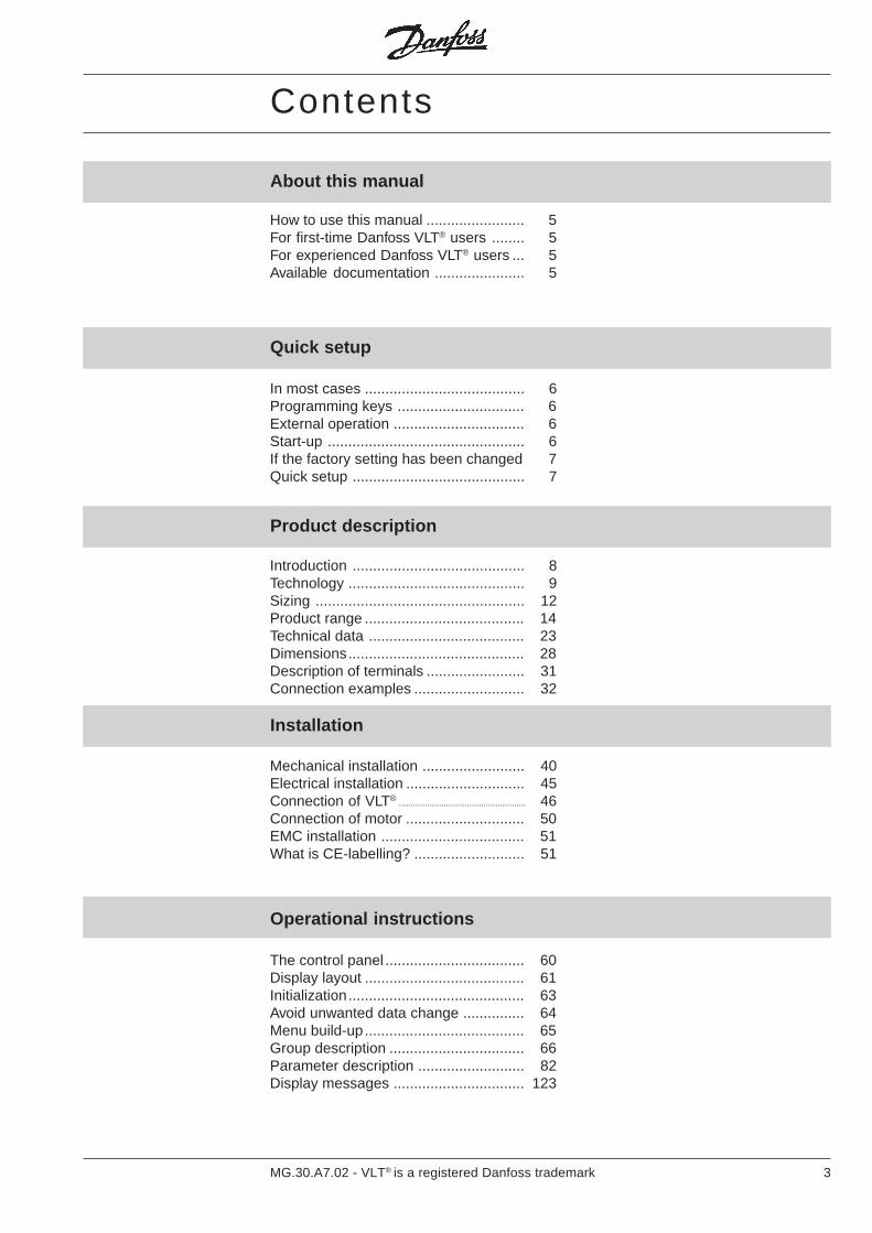
Contents
Product description
Quick setup
How to use this manual ........................ 5For first-time Danfoss VLT® users ........ 5For experienced Danfoss VLT® users ... 5Available documentation ...................... 5
In most cases ....................................... 6Programming keys ............................... 6External operation ................................ 6Start-up ................................................ 6If the factory setting has been changed 7Quick setup .......................................... 7
Introduction .......................................... 8Technology ........................................... 9Sizing ................................................... 12Product range ....................................... 14Technical data ...................................... 23Dimensions........................................... 28Description of terminals ........................ 31Connection examples ........................... 32
About this manual
Installation
Mechanical installation ......................... 40Electrical installation ............................. 45Connection of VLT® ...................................................... 46Connection of motor ............................. 50EMC installation ................................... 51What is CE-labelling? ........................... 51
The control panel .................................. 60Display layout ....................................... 61Initialization........................................... 63Avoid unwanted data change ............... 64Menu build-up....................................... 65Group description ................................. 66Parameter description .......................... 82Display messages ................................ 123
Operational instructions

4 MG.30.A7.02 - VLT® is a registered Danfoss trademark
Special conditions
Galvanic isolation -Earth leakage current ........................... 128Extreme running conditions .................. 129du/dt and peak voltage on motor .......... 130Acoustic noise ...................................... 130Thermal motor protection ..................... 130Derating ................................................ 131EMC testresults .................................... 134Vibration and shock .............................. 137Air humidity .......................................... 137Efficiency .............................................. 138Mains supplyinterference / harmonics ....................... 139Power factor ......................................... 139
Service
Fault messages ................................... 140Electrostatic discharge (ESD)............... 141Fault location ........................................ 142
Accessories
External mountingof display .............................................. 146Connection of brake resistors ............... 146Connection of option cards ................... 146Mounting of bonding plate forUL approval .......................................... 148Mounting of fan option .......................... 148
Factory settings
Factory settings .................................... 149
Index
Index .................................................... 154

5MG.30.A7.02 - VLT® is a registered Danfoss trademark
About this manual
How to use this manual This manual has sections on the VLT®’sperformance and on installation and oper-ation of the VLT®, as well as a section onspecial conditions.
There is also a section on service and anappendix for quick referral to factory set-tings. The index can be a help if you wishto look up a specific item in the manual.
For first-time DanfossVLT® users
If you have not used a Danfoss VLT® be-fore, “Quick setup” will be a help, and also“Installation” and “Operational instructions”.
Pay attention to the safety rules on page2 before start-up.
If you already have experience with theDanfoss VLT®, you will find the “Quicksetup” section most useful.
For experienced DanfossVLT® users
For more information see the other sec-tions, of which “EMC-correct installation”and “Special conditions” will be particularlyuseful.
Availabledocumentation
The following chart shows what literatureis available on the VLT® 3000 Series.
Note that there can be deviations be-tween different countries.
Option
Productmanual
MG.30.AX.02
Data sheet
MD.30.AX.02
Allusers
Relayoption
MI.10.AX.YY
PCSoftware
MZ.64.FX.YY
PROFIBUSmanual
MG.10.AX.YY
PROFIBUSdata sheet
MD.10.AX.YY
RFImodule
MI.62.FX.YY
RFIoption
MI.62.GX.YY
RFI - LCmodule
MI.65.FX.YY
Clampmodule
MI.65.IX.YY
Brakemodule
MI.62.GX.YY
LCmodule
MI.65.FX.YY
RFIoption
MI.60.AX.YY
RFIoption
MI.60.BX.YY
Brakeresistor
MI.65.BX.YY
X = Revision of editionYY = Language version
6 MG.30.A7.02 - VLT® is a registered Danfoss trademark
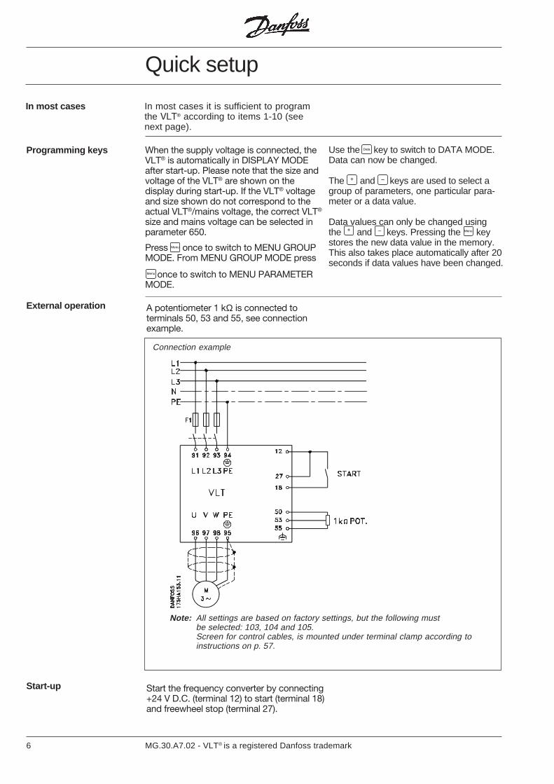
In most cases In most cases it is sufficient to programthe VLT® according to items 1-10 (seenext page).
Note: All settings are based on factory settings, but the following mustbe selected: 103, 104 and 105.Screen for control cables, is mounted under terminal clamp according toinstructions on p. 57.
Connection example
Programming keys When the supply voltage is connected, theVLT® is automatically in DISPLAY MODEafter start-up. Please note that the size andvoltage of the VLT® are shown on thedisplay during start-up. If the VLT® voltageand size shown do not correspond to theactual VLT®/mains voltage, the correct VLT®
size and mains voltage can be selected inparameter 650.
A potentiometer 1 kΩ is connected toterminals 50, 53 and 55, see connectionexample.
External operation
Start the frequency converter by connecting+24 V D.C. (terminal 12) to start (terminal 18)and freewheel stop (terminal 27).
Start-up
Press once to switch to MENU GROUPMODE. From MENU GROUP MODE press
Menu
Menu once to switch to MENU PARAMETERMODE.
Use the Data key to switch to DATA MODE.Data can now be changed.
The + and – keys are used to select agroup of parameters, one particular para-meter or a data value.
Data values can only be changed usingthe + and – keys. Pressing the Menu keystores the new data value in the memory.This also takes place automatically after 20seconds if data values have been changed.
Quick setup
7MG.30.A7.02 - VLT® is a registered Danfoss trademark
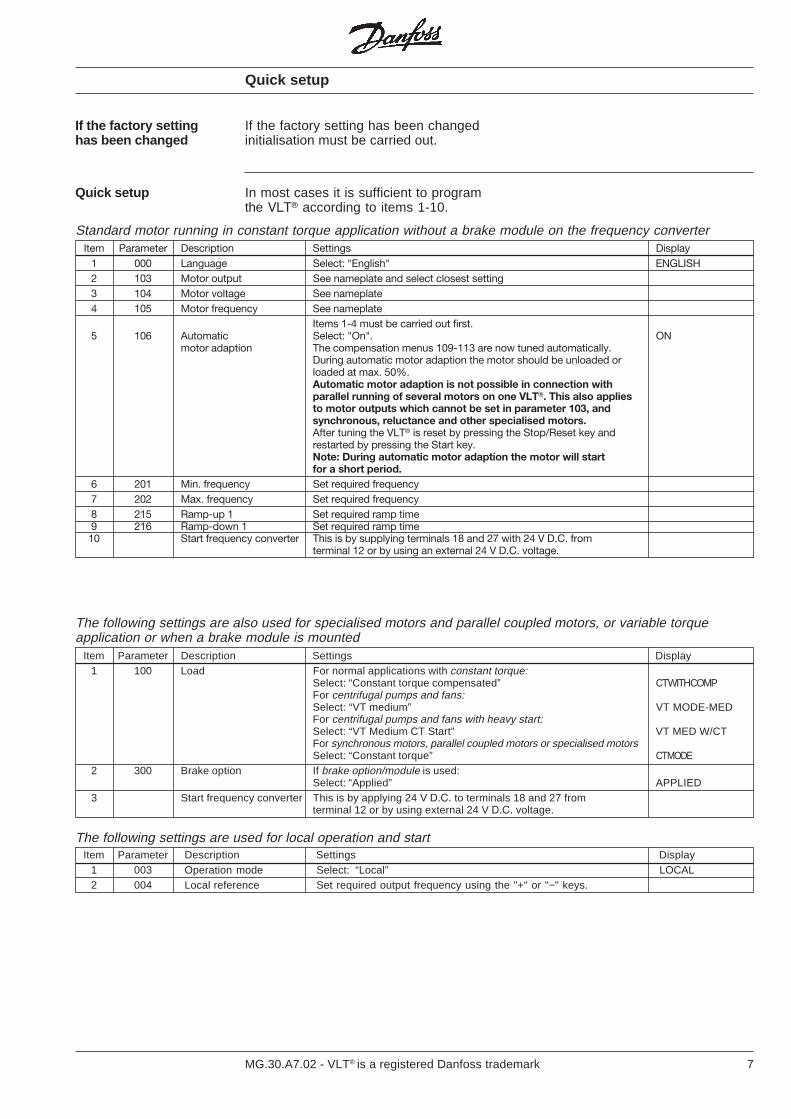
Item Parameter Description Settings Display1 000 Language Select: "English" ENGLISH2 103 Motor output See nameplate and select closest setting3 104 Motor voltage See nameplate4 105 Motor frequency See nameplate
Items 1-4 must be carried out first.5 106 Automatic Select: "On". ON
motor adaption The compensation menus 109-113 are now tuned automatically.During automatic motor adaption the motor should be unloaded orloaded at max. 50%.Automatic motor adaption is not possible in connection withparallel running of several motors on one VLT®. This also appliesto motor outputs which cannot be set in parameter 103, andsynchronous, reluctance and other specialised motors.After tuning the VLT® is reset by pressing the Stop/Reset key andrestarted by pressing the Start key.Note: During automatic motor adaption the motor will startfor a short period.
6 201 Min. frequency Set required frequency7 202 Max. frequency Set required frequency8 215 Ramp-up 1 Set required ramp time9 216 Ramp-down 1 Set required ramp time10 Start frequency converter This is by supplying terminals 18 and 27 with 24 V D.C. from
terminal 12 or by using an external 24 V D.C. voltage.
Quick setup
If the factory settinghas been changed
If the factory setting has been changedinitialisation must be carried out.
In most cases it is sufficient to programthe VLT® according to items 1-10.
Quick setup
Standard motor running in constant torque application without a brake module on the frequency converter
The following settings are also used for specialised motors and parallel coupled motors, or variable torqueapplication or when a brake module is mounted
Item Parameter Description Settings Display1 100 Load For normal applications with constant torque:
Select: “Constant torque compensated” CT WITH COMPFor centrifugal pumps and fans:Select: “VT medium” VT MODE-MEDFor centrifugal pumps and fans with heavy start:Select: “VT Medium CT Start” VT MED W/CTFor synchronous motors, parallel coupled motors or specialised motorsSelect: “Constant torque” CT MODE
2 300 Brake option If brake option/module is used:Select: “Applied” APPLIED
3 Start frequency converter This is by applying 24 V D.C. to terminals 18 and 27 fromterminal 12 or by using external 24 V D.C. voltage.
The following settings are used for local operation and startItem Parameter Description Settings Display
1 003 Operation mode Select: “Local” LOCAL2 004 Local reference Set required output frequency using the "+" or "−" keys.

8 MG.30.A7.02 - VLT® is a registered Danfoss trademark
A frequency converter rectifies the a.c.voltage to D.C. voltage and then convertsthis D.C. voltage to A.C. voltage withvariable amplitude and frequency.
The variable voltage and frequencysupplying the motor make possible infinitespeed control of standard three-phaseasynchronous motors.
Control principle
1. Mains supply3 x 200 / 220 / 230 V A.C., 50/60 Hz3 x 380 / 400 / 415 V A.C., 50/60 Hz3 x 440 / 460 / 500 V A.C., 50/60 Hz
2. RectifierThree-phase rectifier bridge rectifiesA.C. to D.C..
3. Intermediate circuitD.C. voltage = √2 x supply voltage.
4. Coils in the intermediate circuitSmooth the D.C. voltage and limitthe mains supply harmonics.
5. Capacitors in the intermediate circuitSmooth- the D.C. voltage.
6. InverterConverts D.C. voltage to variable A.C.voltage and variable frequency.
7. Motor coilsAdvantages of motor coils:• You can use longer motor cables• 100% short-circuit and earth-fault
protected• Unlimited switching at the output of
the frequency converter.• Reduces du/dt.
8. OutputVariable A.C. voltage, 10 -100% ofthe supply voltage.Variable frequency: 0.5-120 / 0.5-500 Hz.
9. Control cardThis section controls and monitors thepower and inverter section, whichgenerates the pulse pattern by meansof which the D.C. voltage is convertedto variable A.C. voltage and variablefrequency.
Introduction
9MG.30.A7.02 - VLT® is a registered Danfoss trademark
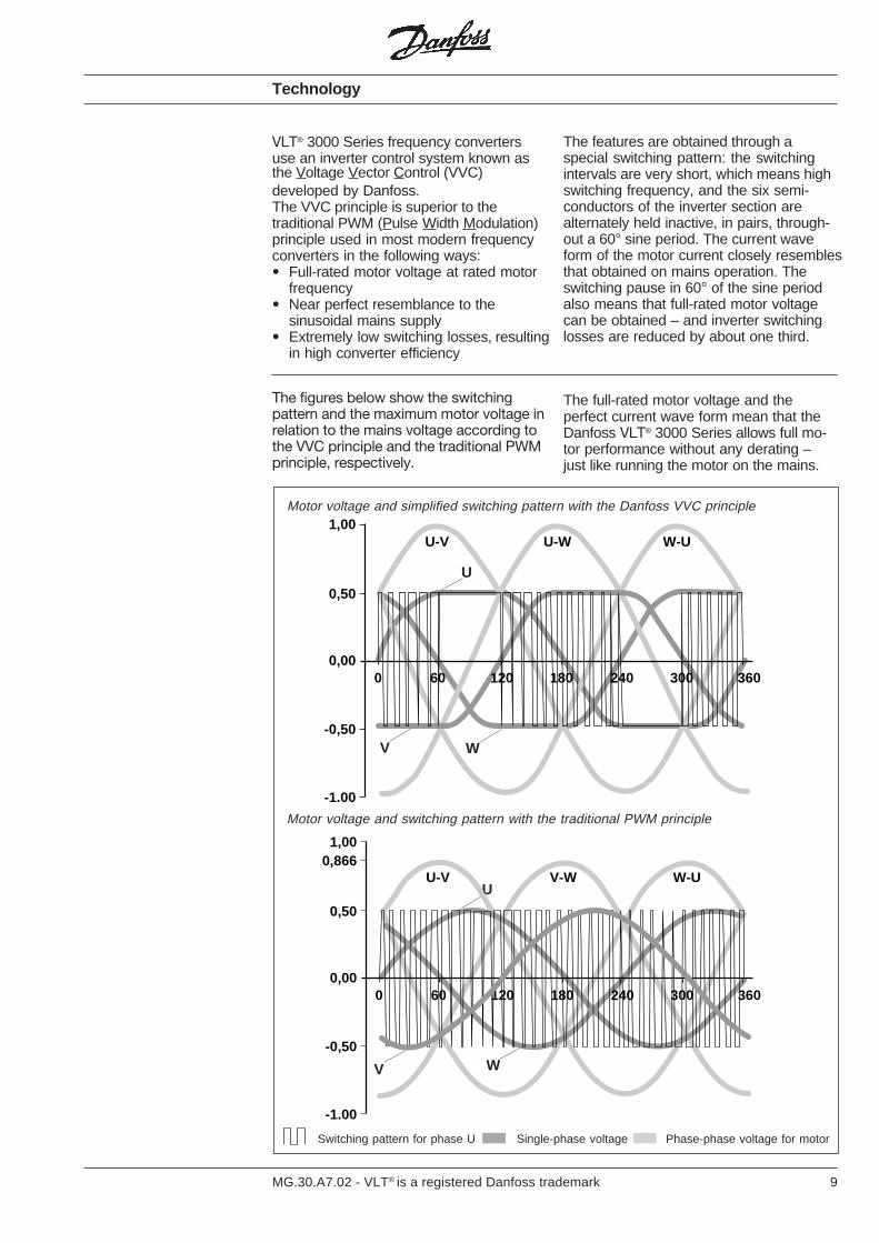
The features are obtained through aspecial switching pattern: the switchingintervals are very short, which means highswitching frequency, and the six semi-conductors of the inverter section arealternately held inactive, in pairs, through-out a 60° sine period. The current waveform of the motor current closely resemblesthat obtained on mains operation. Theswitching pause in 60° of the sine periodalso means that full-rated motor voltagecan be obtained – and inverter switchinglosses are reduced by about one third.
The figures below show the switchingpattern and the maximum motor voltage inrelation to the mains voltage according tothe VVC principle and the traditional PWMprinciple, respectively.
The full-rated motor voltage and theperfect current wave form mean that theDanfoss VLT® 3000 Series allows full mo-tor performance without any derating –just like running the motor on the mains.
Technology
VLT® 3000 Series frequency convertersuse an inverter control system known asthe Voltage Vector Control (VVC)developed by Danfoss.The VVC principle is superior to thetraditional PWM (Pulse Width Modulation)principle used in most modern frequencyconverters in the following ways:• Full-rated motor voltage at rated motor
frequency• Near perfect resemblance to the
sinusoidal mains supply• Extremely low switching losses, resulting
in high converter efficiency
U
V W
U
WV
0,50
0,00
1,00
-0,50
-1.00
0 60 120 180 300 360240
U-V U-W W-U
0,50
0,00
1,00
-0,50
-1.00
0 60 120 180 300 360240
0,866U-V V-W W-U
Motor voltage and switching pattern with the traditional PWM principle
Motor voltage and simplified switching pattern with the Danfoss VVC principle
Switching pattern for phase U Single-phase voltage Phase-phase voltage for motor

10 MG.30.A7.02 - VLT® is a registered Danfoss trademark
The VLT® 3000 Series is delivered with anumber of standard components whichyou would normally have to buy separatelysuch as motor coils, mains reactor DC linkcoil and galvanic insulation (PELV).
These components built-in as standardgive you the following advantages:• Save space and reduce costs• Simplify the installation as the
VLT® 3000 will meet most demands.
Factory programmedU/f characteristics
Technology
Depending on the type of load, theVLT® 3000 Series has dynamic adapting orfactory programmed U/f characteristics(motor voltage/frequency) giving thecorrect magnetisation of the motor, thusensuring optimum dynamic, accuracy orefficiency.
It is possible to choose between 3 U/fcharacteristics for VT operation, offeringthe choice of optimising the start torque orreducing the noise level or power lossesfrom the motor. A new parameter (106)called “Automatic motor tuning” optimizesthe motor parameters at constant loadtorque.
Constant torque CT(Parameter 100)
1: VT low2: VT medium3: VT high
Quadratic torque VT(Parameter 100)
Control accuracy Slip-compensated ±0.5% 5-50 Hz: VLT® 3011-3052(depending on motor size) 10-50 Hz: VLT® 3004-3008
±1.0% 5-50 Hz: VLT® 3004-3052 (10-140% load change)PID (closed loop) ±0.1% 5-50 Hz: (−140 - +140% load change)Open loop (digital) ±0.01% 0.5-120 Hz
0.5-500 Hz±0.05% Frequency resolution (digital)
(10-90% load change)
(frequency stability)
11MG.30.A7.02 - VLT® is a registered Danfoss trademark
It is easy for the user to program therequired functions on the keyboard of theVLT® 3000 Series or via the terminals orthe RS 485 interface.
The digital technique used in the VLT®
3000 Series makes it possible to programthe different control inputs and signaloutputs, and to select 4 different user-defined setups.
Programmablecontrol inputs andsignal outputsin 4 setups
Protected against mainsdisturbance
The VLT® 3000 Series is protected againsttransients arising on the mains, e.g. whenyou switch in power factor phase correctioncapacitors or when the supply is subject tolightning strikes.
Rated motor voltage and full torque can bemaintained down to 10% undervoltage onthe supply mains.
Low disturbance onthe mains
As the VLT® 3000 Series has coils in theintermediate circuit built-in as standard theharmonic generation is low.
This gives a good power factor, thusreducing the harmonic load on the mainssupply.
Effective radiofrequency interferencesuppression (EMC)
Technology
As standard the VLT® 3000 Series isdelivered with built-in motor coils. Thismeans that it is possible to install a long
Current measurement in all three motorphases gives perfect protection of the VLT®
3000 series in the event of short circuits orearth faults on the motor terminals.
The continuous monitoring of the threemotor phases makes switching on themotor cables possible e.g. by opening/closing a contactor.
Long motor cables
AdvancedVLT® protection
cable between motor and frequencyconverter without any additional coils.
Galvanic isolation With the VLT® 3000 Series safety isolationis standard, as the high-voltage parts ofthe power section are galvanically isolatedfrom the low-voltage parts of the controlsection in accordance with VDE 0160/0106(PELV).
Advancedmotor protection
The VLT® 3000 Series has a built-in electro-nic thermal motor protection.The frequency converter calculates themotor temperature on the basis of voltage,current, frequency and time.Therefore it is superior to the traditionalbi-metallic protection where the alteredcooling conditions due to the speed controlare not taken into consideration.
The thermal motor protection is compar-able with thermal relay in the motor cables.To achieve optimum protection againstoverheating of the motor when covered orblocked, or in case the ventilation shouldfail, it is possible to build in a thermistorand connect this to the frequency con-verter thermistor input (terminal 16, seepage 102).
The effective monitoring of the three supplyphases means that the VLT® 3000 Seriesstops in the event of a missing phase. Inthis way overloading of the inverter and thecapacitors of the intermediate circuit, whichwould reduce the lifetime of the frequencyconverter drastically, can be avoided.
The VLT® 3000 Series has built-in thermalprotection of the unit as standard. Thefunction turns off the inverter on thermaloverload.
The VLT® 3000 Series can be delivered withan RFI filter complying with EN 55011.Filters are available as options or modules.
Some VLT® types have a mains filter asstandard in compliance with grade 1, class A.

12 MG.30.A7.02 - VLT® is a registered Danfoss trademark
Choice of frequencyconverter size
The frequency converter must be chosenon the basis of the actual motor current IMat maximum load of the plant.
The rated continuous output current IVLT,N
must be equal to or higher than therequired motor current.
Sizing
Example:In a heating plant (quadratic load) thepump motor is a 7.5 kW, 3 x 380 V, whichat max. load takes up 14 A.Choose a VLT® 3008 which can supply16 A (IVLT,N) continuously.
Mains: 3 x 200/220/230 V and 3 x 220/230/240 V (see technical data)Which oneto choose?
The VLT® types largerthan 3004 (3008 at 500 V) havea higher output when usingquadratic load,referred to as VT load(variable torque).Some technical specificationsmight change fromCT to VT mode (e.g. the max.motor cable lengthdecreases).
: Intermittent operation: In continuous operation some specifications might change
CT VT CT VT CT VT
Typical shaft Constant output Constant output
VLT® type output current I VLT.N power at 230 V
[kW] [A] [kVA]
3002 1.1 5.4 2.1
3003 1.5 7.8 3.1
3004 2.2 10.5 4.2
3006 4.0 5.5 19 25 7.6 10.0
3008 5.5 7.5 25 32 10.0 12.7
3011 7.5 11 32 46 12.7 18.3
3016 11 15 46 61 18.3 24.3
3022 15 22 61 88 24.3 35.1
3032 22 30 80 104 31.9 41.4
3042 30 37 104 130 41.4 51.8
3052 37 45 130 154 51.8 61.3
CT: Constant torqueVT: Variable torque (quadratic load)
13MG.30.A7.02 - VLT® is a registered Danfoss trademark
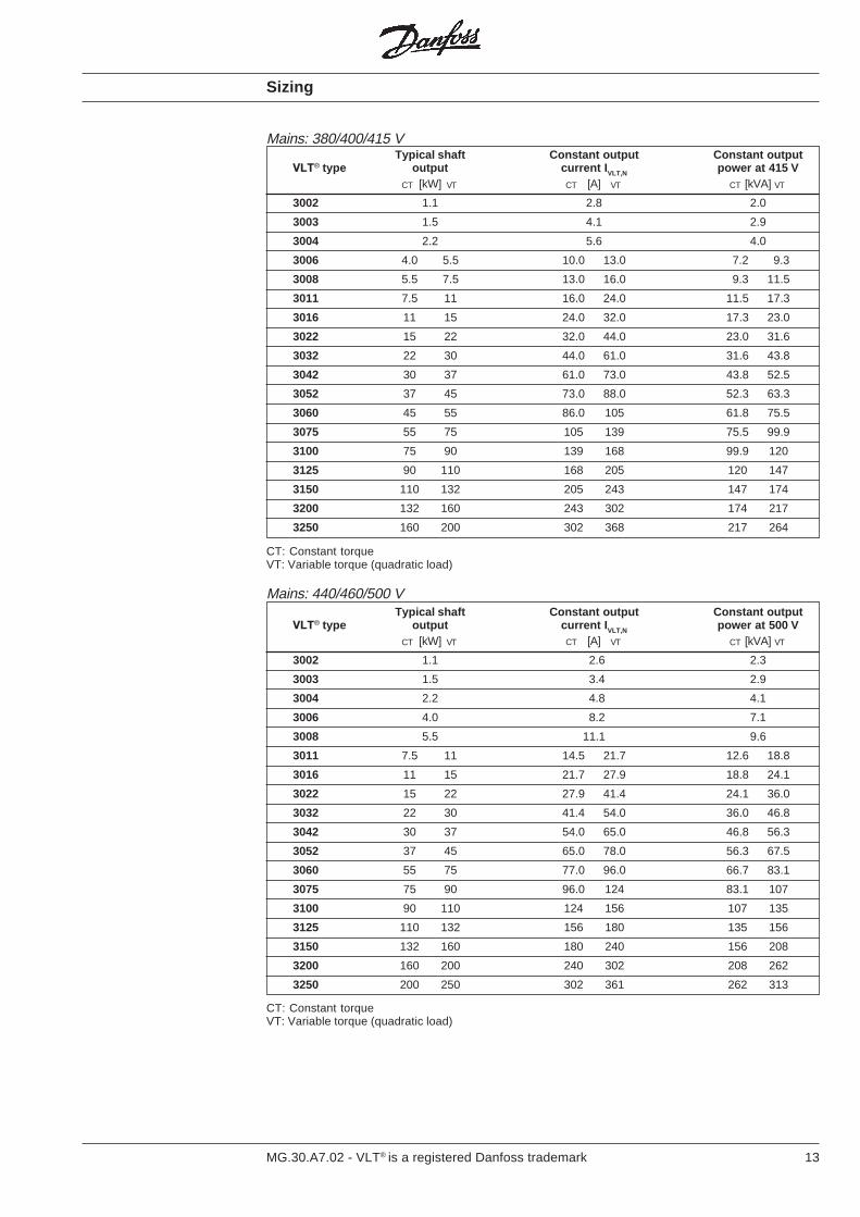
Mains: 380/400/415 VTypical shaft Constant output Constant output
VLT® type output current I VLT,N power at 415 V[kW] [A] [kVA]
3002 1.1 2.8 2.0
3003 1.5 4.1 2.9
3004 2.2 5.6 4.0
3006 4.0 5.5 10.0 13.0 7.2 9.3
3008 5.5 7.5 13.0 16.0 9.3 11.5
3011 7.5 11 16.0 24.0 11.5 17.3
3016 11 15 24.0 32.0 17.3 23.0
3022 15 22 32.0 44.0 23.0 31.6
3032 22 30 44.0 61.0 31.6 43.8
3042 30 37 61.0 73.0 43.8 52.5
3052 37 45 73.0 88.0 52.3 63.3
3060 45 55 86.0 105 61.8 75.5
3075 55 75 105 139 75.5 99.9
3100 75 90 139 168 99.9 120
3125 90 110 168 205 120 147
3150 110 132 205 243 147 174
3200 132 160 243 302 174 217
3250 160 200 302 368 217 264
CT VT CT VT
CT: Constant torqueVT: Variable torque (quadratic load)
CT VT CT VTCT VT
CT: Constant torqueVT: Variable torque (quadratic load)
Sizing
Typical shaft Constant output Constant outputVLT® type output current I VLT,N power at 500 V
[kW] [A] [kVA]
3002 1.1 2.6 2.3
3003 1.5 3.4 2.9
3004 2.2 4.8 4.1
3006 4.0 8.2 7.1
3008 5.5 11.1 9.6
3011 7.5 11 14.5 21.7 12.6 18.8
3016 11 15 21.7 27.9 18.8 24.1
3022 15 22 27.9 41.4 24.1 36.0
3032 22 30 41.4 54.0 36.0 46.8
3042 30 37 54.0 65.0 46.8 56.3
3052 37 45 65.0 78.0 56.3 67.5
3060 55 75 77.0 96.0 66.7 83.1
3075 75 90 96.0 124 83.1 107
3100 90 110 124 156 107 135
3125 110 132 156 180 135 156
3150 132 160 180 240 156 208
3200 160 200 240 302 208 262
3250 200 250 302 361 262 313
CT VT
Mains: 440/460/500 V
14 MG.30.A7.02 - VLT® is a registered Danfoss trademark
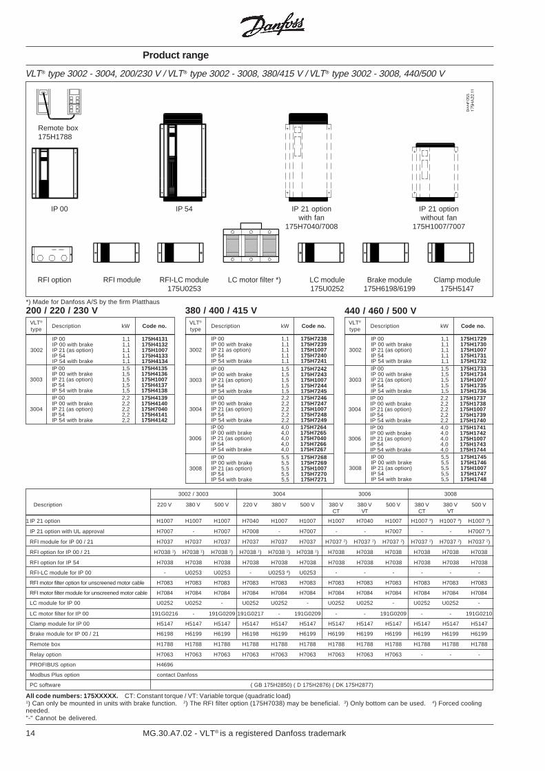
VLT® type 3002 - 3004, 200/230 V / VLT® type 3002 - 3008, 380/415 V / VLT® type 3002 - 3008, 440/500 V
Product range
RFI option RFI module RFI-LC module LC motor filter *) LC module Brake module Clamp module175U0253 175U0252 175H6198/6199 175H5147
*) Made for Danfoss A/S by the firm Platthaus
Remote box175H1788
IP 00 IP 54 IP 21 option IP 21 optionwith fan without fan
175H7040/7008 175H1007/7007
1IP 21 option H1007 H1007 H1007 H7040 H1007 H1007 H1007 H7040 H1007 H1007 3) H1007 3) H1007 3)
IP 21 option with UL approval H7007 - H7007 H7008 - H7007 - - H7007 - - H7007 3)
RFI module for IP 00 / 21 H7037 H7037 H7037 H7037 H7037 H7037 H7037 2) H7037 2) H7037 2) H7037 2) H7037 2) H7037 2)
RFI option for IP 00 / 21 H7038 1) H7038 1) H7038 1) H7038 1) H7038 1) H7038 1) H7038 H7038 H7038 H7038 H7038 H7038
RFI option for IP 54 H7038 H7038 H7038 H7038 H7038 H7038 H7038 H7038 H7038 H7038 H7038 H7038
RFI-LC module for IP 00 - U0253 U0253 - U0253 4) U0253 - - - - - -
RFI motor filter option for unscreened motor cable H7083 H7083 H7083 H7083 H7083 H7083 H7083 H7083 H7083 H7083 H7083 H7083
RFI motor filter module for unscreened motor cable H7084 H7084 H7084 H7084 H7084 H7084 H7084 H7084 H7084 H7084 H7084 H7084
LC module for IP 00 U0252 U0252 - U0252 U0252 - U0252 U0252 - U0252 U0252 -
LC motor filter for IP 00 191G0216 - 191G0209 191G0217 - 191G0209 - - 191G0209 - - 191G0210
Clamp module for IP 00 H5147 H5147 H5147 H5147 H5147 H5147 H5147 H5147 H5147 H5147 H5147 H5147
Brake module for IP 00 / 21 H6198 H6199 H6199 H6198 H6199 H6199 H6199 H6199 H6199 H6199 H6199 H6199
Remote box H1788 H1788 H1788 H1788 H1788 H1788 H1788 H1788 H1788 H1788 H1788 H1788
Relay option H7063 H7063 H7063 H7063 H7063 H7063 H7063 H7063 H7063 - - -
PROFIBUS option H4696
Modbus Plus option contact Danfoss
PC software ( GB 175H2850) ( D 175H2876) ( DK 175H2877)
3002 / 3003 3004 3006 3008
Description 220 V 380 V 500 V 220 V 380 V 500 V 380 V 380 V 500 V 380 V 380 V 500 VCT VT CT VT
All code numbers: 175XXXXX. CT: Constant torque / VT: Variable torque (quadratic load)1) Can only be mounted in units with brake function. 2) The RFI filter option (175H7038) may be beneficial. 3) Only bottom can be used. 4) Forced coolingneeded."-" Cannot be delivered.
200 / 220 / 230 V 380 / 400 / 415 V 440 / 460 / 500 VVLT®
Description kW Code no.type
VLT®
Description kW Code no.type
VLT®
Description kW Code no.type
IP 00 1,1 175H4131IP 00 with brake 1,1 175H4132
3002 IP 21 (as option) 1,1 175H1007IP 54 1,1 175H4133IP 54 with brake 1,1 175H4134IP 00 1,5 175H4135IP 00 with brake 1,5 175H4136
3003 IP 21 (as option) 1,5 175H1007IP 54 1,5 175H4137IP 54 with brake 1,5 175H4138IP 00 2,2 175H4139IP 00 with brake 2,2 175H4140
3004 IP 21 (as option) 2,2 175H7040IP 54 2,2 175H4141IP 54 with brake 2,2 175H4142
IP 00 1,1 175H7238IP 00 with brake 1,1 175H7239
3002 IP 21 as option) 1,1 175H1007IP 54 1,1 175H7240IP 54 with brake 1,1 175H7241IP 00 1,5 175H7242IP 00 with brake 1,5 175H7243
3003 IP 21 (as option) 1,5 175H1007IP 54 1,5 175H7244IP 54 with brake 1,5 175H7245IP 00 2,2 175H7246IP 00 with brake 2,2 175H7247
3004 IP 21 (as option) 2,2 175H1007IP 54 2,2 175H7248IP 54 with brake 2,2 175H7249IP 00 4,0 175H7264IP 00 with brake 4,0 175H7265
3006 IP 21 (as option) 4,0 175H7040IP 54 4,0 175H7266IP 54 with brake 4,0 175H7267IP 00 5,5 175H7268IP 00 with brake 5,5 175H7269
3008 IP 21 (as option) 5,5 175H1007IP 54 5,5 175H7270IP 54 with brake 5,5 175H7271
IP 00 1,1 175H1729IP 00 with brake 1,1 175H1730
3002 IP 21 (as option) 1,1 175H1007IP 54 1,1 175H1731IP 54 with brake 1,1 175H1732IP 00 1,5 175H1733IP 00 with brake 1,5 175H1734
3003 IP 21 (as option) 1,5 175H1007IP 54 1,5 175H1735IP 54 with brake 1,5 175H1736IP 00 2,2 175H1737IP 00 with brake 2,2 175H1738
3004 IP 21 (as option) 2,2 175H1007IP 54 2,2 175H1739IP 54 with brake 2,2 175H1740IP 00 4,0 175H1741IP 00 with brake 4,0 175H1742
3006 IP 21 (as option) 4,0 175H1007IP 54 4,0 175H1743IP 54 with brake 4,0 175H1744IP 00 5,5 175H1745IP 00 with brake 5,5 175H1746
3008 IP 21 (as option) 5,5 175H1007IP 54 5,5 175H1747IP 54 with brake 5,5 175H1748
15MG.30.A7.02 - VLT® is a registered Danfoss trademark
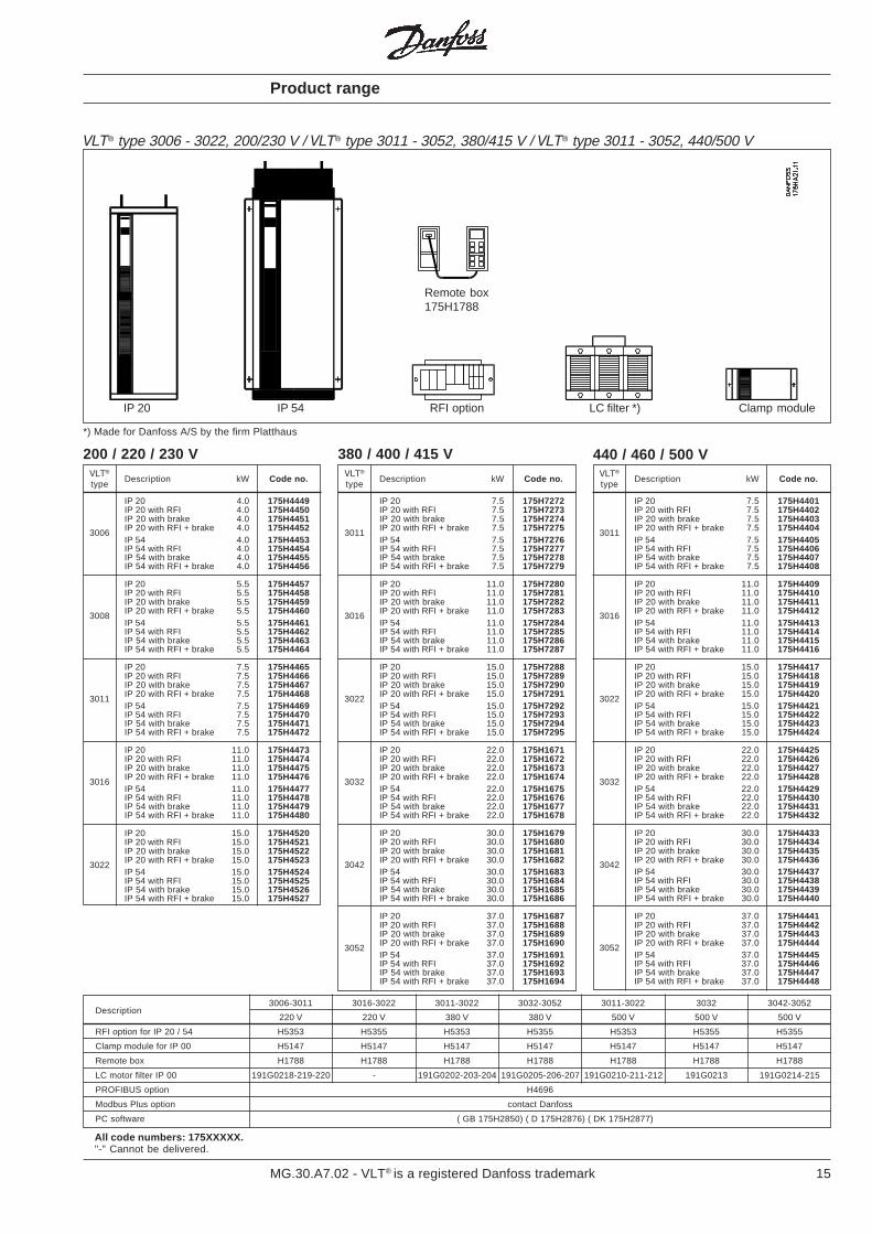
VLT® type 3006 - 3022, 200/230 V / VLT® type 3011 - 3052, 380/415 V / VLT® type 3011 - 3052, 440/500 V
Product range
IP 20 IP 54 RFI option LC filter *) Clamp module
*) Made for Danfoss A/S by the firm Platthaus
IP 20 4.0 175H4449IP 20 with RFI 4.0 175H4450IP 20 with brake 4.0 175H4451IP 20 with RFI + brake 4.0 175H44523006IP 54 4.0 175H4453IP 54 with RFI 4.0 175H4454IP 54 with brake 4.0 175H4455IP 54 with RFI + brake 4.0 175H4456
IP 20 5.5 175H4457IP 20 with RFI 5.5 175H4458IP 20 with brake 5.5 175H4459IP 20 with RFI + brake 5.5 175H44603008IP 54 5.5 175H4461IP 54 with RFI 5.5 175H4462IP 54 with brake 5.5 175H4463IP 54 with RFI + brake 5.5 175H4464
IP 20 7.5 175H4465IP 20 with RFI 7.5 175H4466IP 20 with brake 7.5 175H4467IP 20 with RFI + brake 7.5 175H44683011IP 54 7.5 175H4469IP 54 with RFI 7.5 175H4470IP 54 with brake 7.5 175H4471IP 54 with RFI + brake 7.5 175H4472
IP 20 11.0 175H4473IP 20 with RFI 11.0 175H4474IP 20 with brake 11.0 175H4475IP 20 with RFI + brake 11.0 175H44763016IP 54 11.0 175H4477IP 54 with RFI 11.0 175H4478IP 54 with brake 11.0 175H4479IP 54 with RFI + brake 11.0 175H4480
IP 20 15.0 175H4520IP 20 with RFI 15.0 175H4521IP 20 with brake 15.0 175H4522IP 20 with RFI + brake 15.0 175H45233022IP 54 15.0 175H4524IP 54 with RFI 15.0 175H4525IP 54 with brake 15.0 175H4526IP 54 with RFI + brake 15.0 175H4527
200 / 220 / 230 V 380 / 400 / 415 V 440 / 460 / 500 VVLT®
Description kW Code no.type
IP 20 7.5 175H7272IP 20 with RFI 7.5 175H7273IP 20 with brake 7.5 175H7274IP 20 with RFI + brake 7.5 175H72753011IP 54 7.5 175H7276IP 54 with RFI 7.5 175H7277IP 54 with brake 7.5 175H7278IP 54 with RFI + brake 7.5 175H7279
IP 20 11.0 175H7280IP 20 with RFI 11.0 175H7281IP 20 with brake 11.0 175H7282IP 20 with RFI + brake 11.0 175H72833016IP 54 11.0 175H7284IP 54 with RFI 11.0 175H7285IP 54 with brake 11.0 175H7286IP 54 with RFI + brake 11.0 175H7287
IP 20 15.0 175H7288IP 20 with RFI 15.0 175H7289IP 20 with brake 15.0 175H7290IP 20 with RFI + brake 15.0 175H72913022IP 54 15.0 175H7292IP 54 with RFI 15.0 175H7293IP 54 with brake 15.0 175H7294IP 54 with RFI + brake 15.0 175H7295
IP 20 22.0 175H1671IP 20 with RFI 22.0 175H1672IP 20 with brake 22.0 175H1673IP 20 with RFI + brake 22.0 175H16743032IP 54 22.0 175H1675IP 54 with RFI 22.0 175H1676IP 54 with brake 22.0 175H1677IP 54 with RFI + brake 22.0 175H1678
IP 20 30.0 175H1679IP 20 with RFI 30.0 175H1680IP 20 with brake 30.0 175H1681IP 20 with RFI + brake 30.0 175H16823042IP 54 30.0 175H1683IP 54 with RFI 30.0 175H1684IP 54 with brake 30.0 175H1685IP 54 with RFI + brake 30.0 175H1686
IP 20 37.0 175H1687IP 20 with RFI 37.0 175H1688IP 20 with brake 37.0 175H1689IP 20 with RFI + brake 37.0 175H16903052IP 54 37.0 175H1691IP 54 with RFI 37.0 175H1692IP 54 with brake 37.0 175H1693IP 54 with RFI + brake 37.0 175H1694
VLT®
Description kW Code no.type
IP 20 7.5 175H4401IP 20 with RFI 7.5 175H4402IP 20 with brake 7.5 175H4403IP 20 with RFI + brake 7.5 175H44043011IP 54 7.5 175H4405IP 54 with RFI 7.5 175H4406IP 54 with brake 7.5 175H4407IP 54 with RFI + brake 7.5 175H4408
IP 20 11.0 175H4409IP 20 with RFI 11.0 175H4410IP 20 with brake 11.0 175H4411IP 20 with RFI + brake 11.0 175H44123016IP 54 11.0 175H4413IP 54 with RFI 11.0 175H4414IP 54 with brake 11.0 175H4415IP 54 with RFI + brake 11.0 175H4416
IP 20 15.0 175H4417IP 20 with RFI 15.0 175H4418IP 20 with brake 15.0 175H4419IP 20 with RFI + brake 15.0 175H44203022IP 54 15.0 175H4421IP 54 with RFI 15.0 175H4422IP 54 with brake 15.0 175H4423IP 54 with RFI + brake 15.0 175H4424
IP 20 22.0 175H4425IP 20 with RFI 22.0 175H4426IP 20 with brake 22.0 175H4427IP 20 with RFI + brake 22.0 175H44283032IP 54 22.0 175H4429IP 54 with RFI 22.0 175H4430IP 54 with brake 22.0 175H4431IP 54 with RFI + brake 22.0 175H4432
IP 20 30.0 175H4433IP 20 with RFI 30.0 175H4434IP 20 with brake 30.0 175H4435IP 20 with RFI + brake 30.0 175H44363042IP 54 30.0 175H4437IP 54 with RFI 30.0 175H4438IP 54 with brake 30.0 175H4439IP 54 with RFI + brake 30.0 175H4440
IP 20 37.0 175H4441IP 20 with RFI 37.0 175H4442IP 20 with brake 37.0 175H4443IP 20 with RFI + brake 37.0 175H44443052IP 54 37.0 175H4445IP 54 with RFI 37.0 175H4446IP 54 with brake 37.0 175H4447IP 54 with RFI + brake 37.0 175H4448
VLT®
Description kW Code no.type
RFI option for IP 20 / 54 H5353 H5355 H5353 H5355 H5353 H5355 H5355
Clamp module for IP 00 H5147 H5147 H5147 H5147 H5147 H5147 H5147
Remote box H1788 H1788 H1788 H1788 H1788 H1788 H1788
LC motor filter IP 00 191G0218-219-220 - 191G0202-203-204 191G0205-206-207 191G0210-211-212 191G0213 191G0214-215
PROFIBUS option H4696
Modbus Plus option contact Danfoss
PC software ( GB 175H2850) ( D 175H2876) ( DK 175H2877)
3006-3011 3016-3022 3011-3022 3032-3052 3011-3022 3032 3042-3052Description
220 V 220 V 380 V 380 V 500 V 500 V 500 V
Remote box175H1788
All code numbers: 175XXXXX."-" Cannot be delivered.
16 MG.30.A7.02 - VLT® is a registered Danfoss trademark
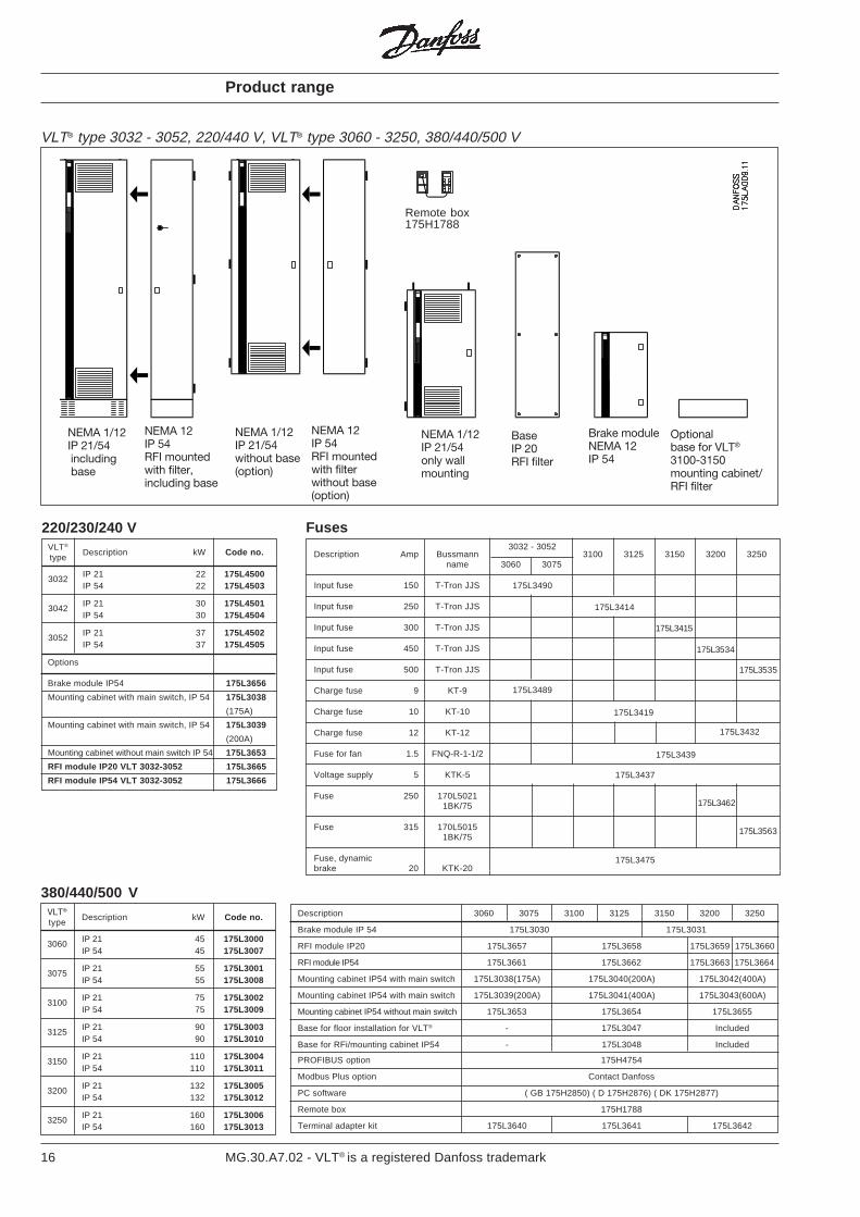
VLT® type 3032 - 3052, 220/440 V, VLT® type 3060 - 3250, 380/440/500 V
Product range
NEMA 1/12IP 21/54only wallmounting
BaseIP 20RFI filter
NEMA 1/12IP 21/54 including base
NEMA 12IP 54RFI mountedwith filter,including base
Optionalbase for VLT®
3100-3150mounting cabinet/RFI filter
Brake moduleNEMA 12IP 54
NEMA 1/12IP 21/54without base(option)
NEMA 12IP 54RFI mountedwith filterwithout base(option)
Remote box175H1788
IP 21 45 175L30003060IP 54 45 175L3007
IP 21 55 175L30013075IP 54 55 175L3008
IP 21 75 175L30023100IP 54 75 175L3009
IP 21 90 175L30033125IP 54 90 175L3010
IP 21 110 175L30043150IP 54 110 175L3011
IP 21 132 175L30053200IP 54 132 175L3012
IP 21 160 175L30063250IP 54 160 175L3013
380/440/500 VVLT®
Description kW Code no.type
175L3535
175L3437
175L3490
175L3489
175L3414
175L3415
175L3534
175L3432
175L3419
175L3462
175L3563
175L3475
175L3439
Fuses
Description Amp Bussmann 3100 3125 3150 3200 3250name 3060 3075
Input fuse 150 T-Tron JJS
Input fuse 250 T-Tron JJS
Input fuse 300 T-Tron JJS
Input fuse 450 T-Tron JJS
Input fuse 500 T-Tron JJS
Charge fuse 9 KT-9
Charge fuse 10 KT-10
Charge fuse 12 KT-12
Fuse for fan 1.5 FNQ-R-1-1/2
Voltage supply 5 KTK-5
Fuse 250 170L50211BK/75
Fuse 315 170L50151BK/75
Fuse, dynamicbrake 20 KTK-20
IP 21 22 175L45003032IP 54 22 175L4503
IP 21 30 175L45013042IP 54 30 175L4504
IP 21 37 175L45023052IP 54 37 175L4505
Options
Brake module IP54 175L3656
Mounting cabinet with main switch, IP 54 175L3038
(175A)
Mounting cabinet with main switch, IP 54 175L3039
(200A)
Mounting cabinet without main switch IP 54 175L3653
RFI module IP20 VLT 3032-3052 175L3665
RFI module IP54 VLT 3032-3052 175L3666
220/230/240 VVLT®
Description kW Code no.type
Description 3060 3075 3100 3125 3150 3200 3250
Brake module IP 54 175L3030 175L3031
RFI module IP20 175L3657 175L3658 175L3659 175L3660
RFI module IP54 175L3661 175L3662 175L3663 175L3664
Mounting cabinet IP54 with main switch 175L3038(175A) 175L3040(200A) 175L3042(400A)
Mounting cabinet IP54 with main switch 175L3039(200A) 175L3041(400A) 175L3043(600A)
Mounting cabinet IP54 without main switch 175L3653 175L3654 175L3655
Base for floor installation for VLT® - 175L3047 Included
Base for RFi/mounting cabinet IP54 - 175L3048 Included
PROFIBUS option 175H4754
Modbus Plus option Contact Danfoss
PC software ( GB 175H2850) ( D 175H2876) ( DK 175H2877)
Remote box 175H1788
Terminal adapter kit 175L3640 175L3641 175L3642
3032 - 3052
17MG.30.A7.02 - VLT® is a registered Danfoss trademark
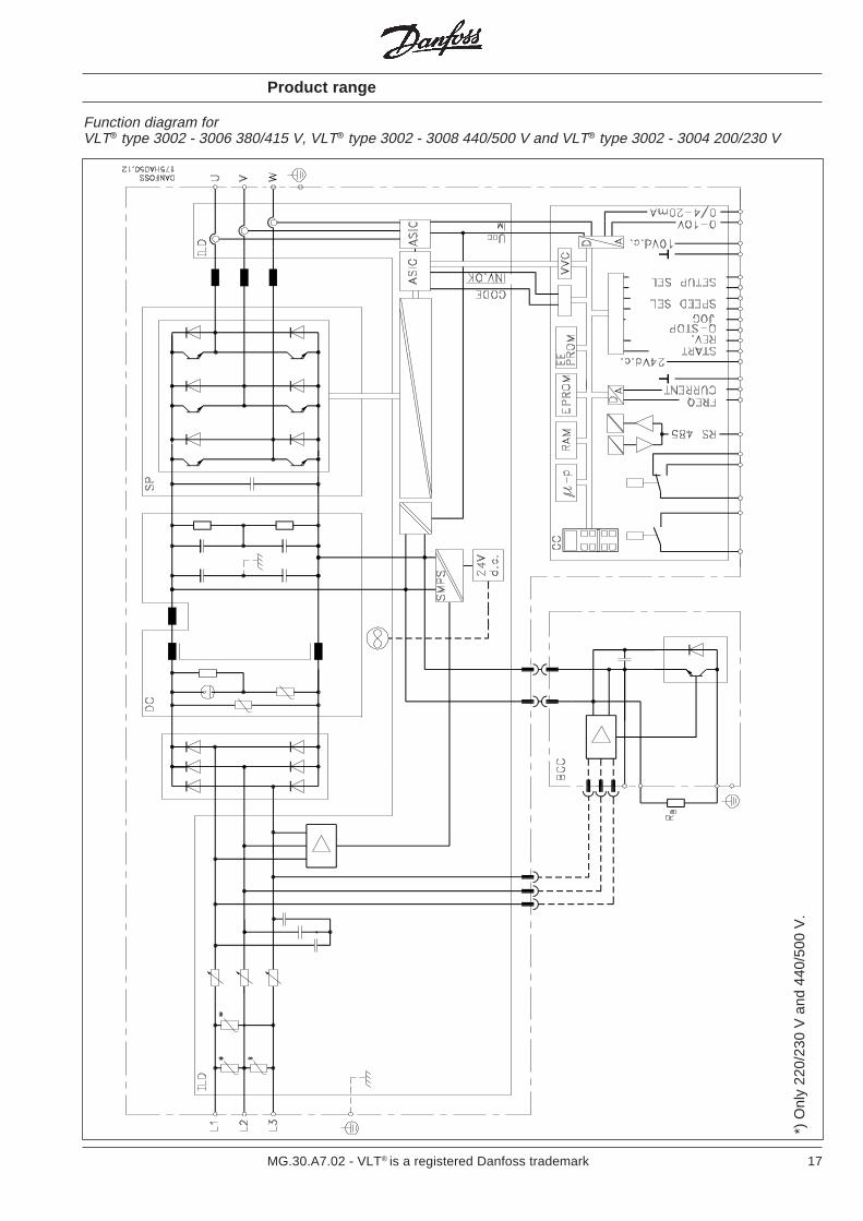
Product range
Function diagram forVLT® type 3002 - 3006 380/415 V, VLT® type 3002 - 3008 440/500 V and VLT® type 3002 - 3004 200/230 V
*) O
nly
220/
230
V a
nd 4
40/5
00 V
.
18 MG.30.A7.02 - VLT® is a registered Danfoss trademark
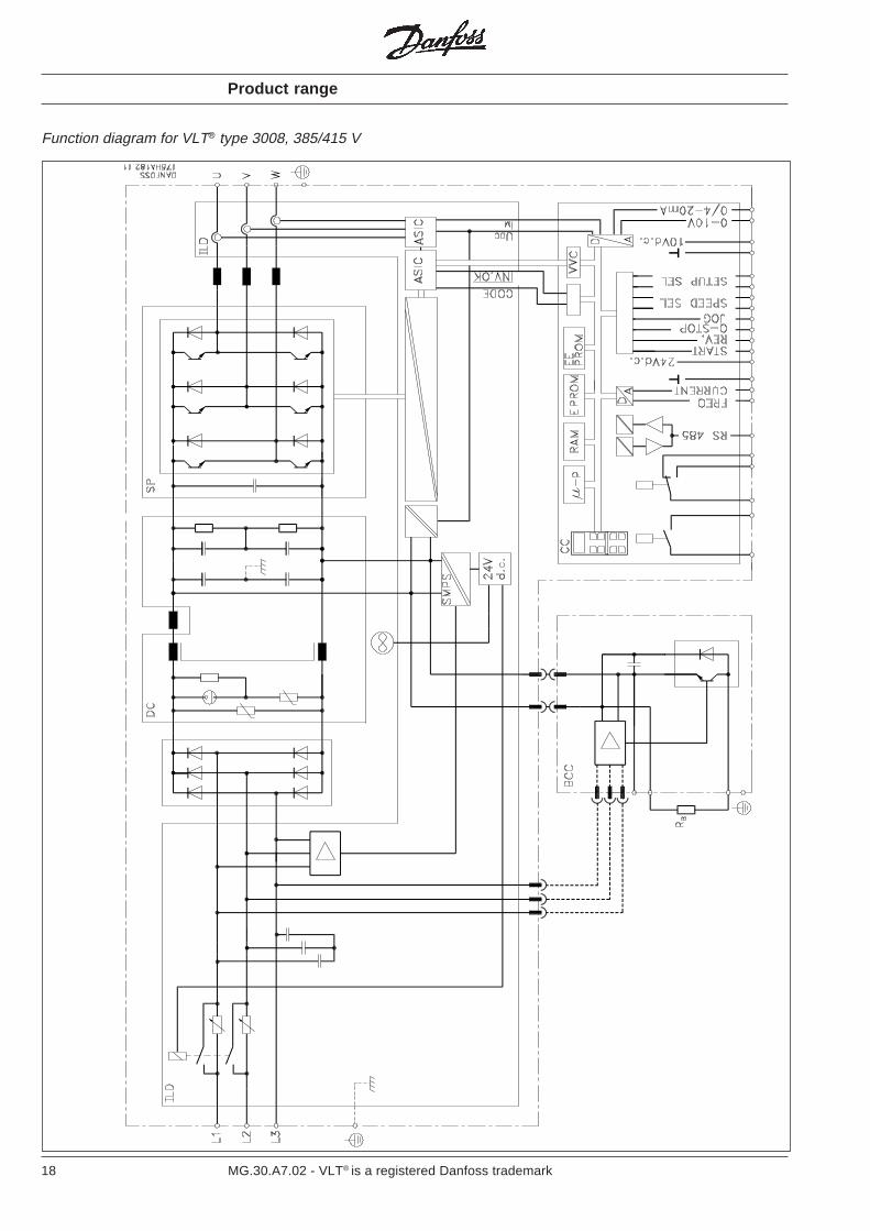
Function diagram for VLT® type 3008, 385/415 V
Product range
19MG.30.A7.02 - VLT® is a registered Danfoss trademark
Function diagram for VLT® type 3011 - 3052 380/500 V, VLT® type 3006 - 3022 200/230 V
Product range

20 MG.30.A7.02 - VLT® is a registered Danfoss trademark
Function diagram for VLT® type 3032 - 3052, 220/240 V, VLT® type 3060 - 3075 (380/500 V)
Product range
21MG.30.A7.02 - VLT® is a registered Danfoss trademark
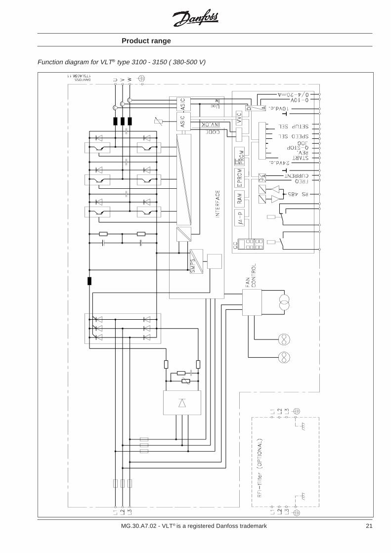
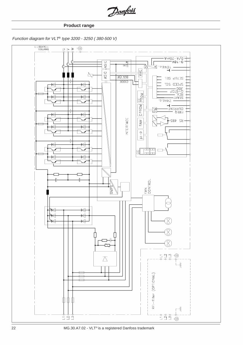
Function diagram for VLT® type 3100 - 3150 ( 380-500 V)
Product range
22 MG.30.A7.02 - VLT® is a registered Danfoss trademark
Function diagram for VLT® type 3200 - 3250 ( 380-500 V)
Product range

23MG.30.A7.02 - VLT® is a registered Danfoss trademark
Mains supply 3 x 200/220/230 V and 3 x 220/230/240 V Technical data
According to international VDE and UL/CSA requirements VLT type 3002 3003 3004 3006 3008 3011 3016 3022 3032 3042 3052Constant torque (CT):Output current IVLT,N [A] 5.4 7.8 10.5 19.0 25.0 32.0 46.0 61.0 80.0 104.0 130.0
IVLT,MAX [A] (60 s) 6.7 12.5 17.0 30.0 40.0 51.2 73.6 97.6 120.0 156.0 195.0Output SVLT,N [kVA] 2.1 3.1 4.2 7.6 10.0 12.7 18.3 24.3 31.9 41.4 51.8
SVLT,MAX [kVA] (60 s) 2.7 4.9 6.7 12.0 15.9 20.4 29.2 38.9 47.8 62.1 77.7Typical shaft output PVLT,N [kW] 1.1 1.5 2.2 4.0 5.5 7.5 11.0 15.0 22.0 30.0 37.0Quadratic torque (VT):Output current IVLT,N [A] 5.4 7.8 10.5 25.0 32.0 46.0 61.0 88.0 104.0 130.0 154.0Output SVLT,N [kVA] 1.9 2.9 4.0 10.0 12.7 18.3 24.3 35.1 41.4 51.8 61.3Typical shaft output PVLT,N [kW] 1.1 1.5 2.2 5.5 7.5 11,0 15,0 22.0 33.0 37.0 45.0Max. cable cross-section [mm2] 2.5 2.5 2.5 16.0 16.0 16.0 35.0 50.0 70.0 70.0 70.0Max. motor cable length [m] 300, with screened cables: 150 m 300Output voltage UM [%] 0-100, of mains voltage max. 230 VOutput frequency fM [Hz] 0-120 or 0-500; programmableRated motor voltage UM,N [V] 200/220/230Rated motor frequency fM,N [Hz] 50/60/87/100Thermal protection during operation Integrated thermal motor protection (electronic);
thermistor to DIN 44081Switching on output Unlimited (frequent switching on output may result
in fault message)Ramp times [s] 0.1 - 3600
VLT type 3002 3003 3004 3006 3008 3011 3016 3022 3032 3042 3052Max. input current const. load IL,N [A] 6.8 9.1 13.3 17.5 22.2 26.4 41.7 52.2 78.0 102.0 128.0
quad. load IL,N [A] 6.8 9.1 13.3 23.1 29.6 42.0 56.8 72.3 102.0 128.0 152.0Max. cable cross-section [mm2] 2.5 2.5 2.5 16.0 16.0 16.0 35.0 50.0 120.0 120.0 120.0Max. pre-fuses1) [A] 16.0 16.0 25.0 40.0 50.0 60.0 80.0 125.0 150.0 150.0 150.0Supply voltage (VDE 0160) [V] 3 x 200/220/230 ±10% 3 x 220/230/240Supply frequency [Hz] 50/60Power factor / cos. ϕ1 0.9/1.0Efficiency 0.96 at 100% loadSwitching on input times/min. times/min. 2
VLT type 3002 3003 3004 3006 3008 3011 3016 3022 3032 3042 3052
Weight (kg)
IP 00 7.4 7.4 7.4 - - - - - - - -IP 20 - - - 24.0 26.0 32.0 49.0 51.0 - - -IP 21 8.0 8.0 8.0 - - - - - 143.0 145.0 147.0IP 54 11.0 11.0 11.0 34.0 37.0 48.0 63.0 65.0 143.0 145.0 147.0
Power loss CT [W] 60.0 100.0 130.0 270.0 425.0 399.0 615.0 935.0 760.0 910.0 1110at max. load VT [W] 60.0 100.0 130.0 425.0 580.0 651.0 929.0 1350 950.0 1110 1290
EnclosureVLT type 3002-04: IP 00 / IP 21 / IP 54VLT type 3006-22: IP 20 / IP 54VLT type 3032-52: NEMA 1 / 2, IP 21 / 54
Vibration test [g] 0.7Relative humidity [%] VDE 0160 5.2.1.2.
Ambient temperature (to VDE 0160)
[°C] VLT 3002-3004: -10→ +40, operation at full load2)
VLT 3006-3052: -10→ +45/40(CT/VT) at full load2)
[°C] VLT 3002-3004: -30/25→ +65/70, in storage/transportVLT 3006-3052: -25→ +65/70, in storage/transport
Frequency converter protection Protection against earthing and short-circuitingEmission EN 55011, EN 55014
EMC standardsEN 50082-2, IEC 1000-4-2, IEC 1000-4-3, IEC 1000-4-4,
(See section “EMC test results”)Immunity IEC 1000-4-5 VDE 0160, ENV 50140, ENV 50141
+10%+10%+10%+10%+10%-15%-15%-15%-15%-15%
1) VLT 3022: Only semi-conductor fuses; VLT 3032-3052: Bussman rapid type JJS built-in (see list)2) In the range -10 to 0°C, the equipment can start and run; however, the display values and certain operating characteristics will not fulfil the
specifications.

24 MG.30.A7.02 - VLT® is a registered Danfoss trademark
Mains supply 3 x 380/400/415 V Technical data
Acc. to international VDE and UL/CSA requirements VLT type 3002 3003 3004 3006 3008 3011 3016 3022 3032 3042 3052Constant torque (CT):Output current IVLT,N [A] 2.8 4.1 5.6 10.0 13.0 16.0 24.0 32.0 44.0 61.0 73.0
IVLT,MAX [A] (60 s) 3.5 6.5 9.0 16.0 20.8 25.6 38.4 51.2 70.4 97.6 117.0Output SVLT,N [kVA] 2.0 2.9 4.0 7.2 9.3 11.5 17.2 23.0 31.6 44.0 52.5
SVLT,MAX [kVA] (60 s) 2.5 4.6 6.4 11.5 15.0 18.4 27.6 36.8 50.5 70.2 84.1Typical shaft output PVLT,N [kW] 1.1 1.5 2.2 4.0 5.5 7.5 11.0 15.0 22.0 30.0 37.0Quadratic torque (VT):Output current IVLT,N [A] 2.8 4.1 5.6 13.0 16.0 24.0 32.0 44.0 61.0 73.0 88.0Output SVLT,N [kVA] 2.0 2.9 4.0 9.3 11.5 17.2 23.0 31.6 44.0 52.5 63.3Typical shaft output PVLT,N [kW] 1.1 1.5 2.2 5.5 7.5 11.0 15.0 22.0 30.0 37.0 45.0Max. cable cross-section [mm2] 2.5 2.5 2.5 2.5 2.5 16.0 16.0 16.0 35.0 35.0 50.0Max. motor cable length [m] 300, with screened cables: 150 mOutput voltage UM [%] 0-100, of mains voltageOutput frequency fM [Hz] 0-120 or 0-500; programmableRated motor voltage UM,N [V] 380/400/415Rated motor frequency fM,N [Hz] 50/60/87/100
Thermal protection during operationIntegrated thermal motor protection (electronic);thermistor to DIN 44081
Switching on output Unlimited (frequent switching on output may result in fault message)Ramp times [s] 0.1 - 3600
VLT type 3002 3003 3004 3006 3008 3011 3016 3022 3032 3042 3052 Max. input current const. load IL,N [A] 2.8 4.8 7.0 10.0 13.0 13.8 21.8 30.7 41.9 55.6 66.5
quad. load. IL,N [A] 2.8 4.8 7.0 13.0 17.0 22.0 31.0 41.5 57.5 66.5 80.0Max. cable cross-section [mm2] 2.5 2.5 2.5 2.5 2.5 16.0 16.0 16.0 35.0 35.0 50.0Max. pre-fuses [A] 16.0 16.0 16.0 25.0 25.0 50.0 63.0 63.0 80.0 1001) 1251)
Supply voltage [V] 3 x 380/400/415 ±10% (VDE 0160)Supply frequency [Hz] 50/60 HzPower factor / cos. ϕ1 0.9/1.0Efficiency 0,96 at 100% loadSwitching on input times/min. 2
VLT type 3002 3003 3004 3006 3008 3011 3016 3022 3032 3042 3052
Weight (kg)
IP 00 7.4 7.4 7.4 12.0 14.0 - - - - - -IP 20 - - - - - 24.0 26.0 32.0 49.0 54.0 54.0IP 21 8.0 8.0 8.0 13.0 15.0 - - - - - -IP 54 11.0 11.0 11.0 14.0 15.0 34.0 37.0 48.0 63.0 69.0 69.0
Power loss CT [W] 60 100 130 195 200 270 425 580 880 1390 1875at max. load VT [W] 60 100 130 280 300 425 580 880 1390 1875 2155Enclosure VLT type 3002-08: IP 00 / IP 21 / IP 54
VLT type 3011-52: IP 20 / IP 54Vibration test [g] 0.7Relative humidity [%] VDE 0160 5.2.1.2.
[°C] -10→ +40 -10→ +45/40 (CT/VT)Ambient temperature operation at full load2) at full load2)
(to VDE 0160) [°C] -25→ +65/70, -25→ +65/70,in storage/transport in storage/transport
EMC standards Emission EN 55011, EN 55014, EN 61000-3-2(See section “EMC test results”) Immunity EN 50082-2, IEC 1000-4-2, IEC 1000-4-3, IEC 1000-4-4,
IEC 1000-4-5, VDE 0160, ENV 50140, ENV 50141
1) Only semi-conductor fuses.2) In the range -10 to 0°C, the equipment can start and run; however, the display values and certain operating characteristics will not fulfil the
specifications.
25MG.30.A7.02 - VLT® is a registered Danfoss trademark
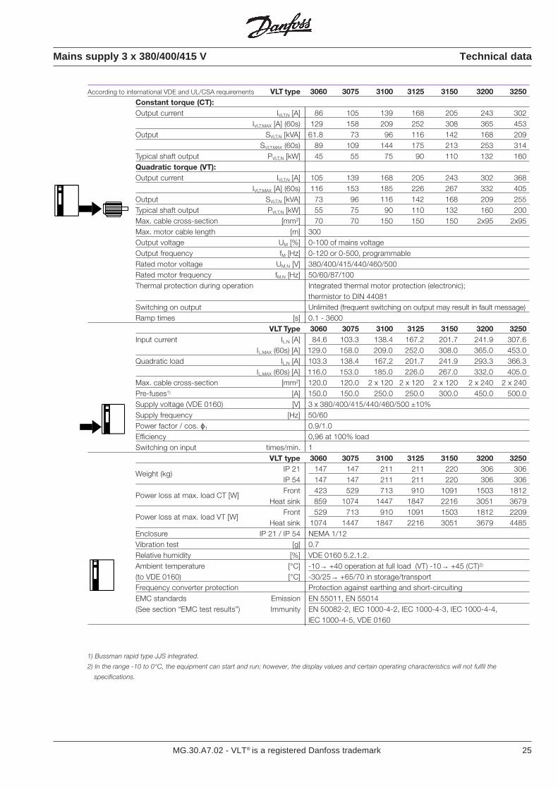
Mains supply 3 x 380/400/415 V Technical data
According to international VDE and UL/CSA requirements VLT type 3060 3075 3100 3125 3150 3200 3250Constant torque (CT):Output current IVLT,N [A] 86 105 139 168 205 243 302
IVLT,MAX [A] (60s) 129 158 209 252 308 365 453Output SVLT,N [kVA] 61.8 73 96 116 142 168 209
SVLT,MAX (60s) 89 109 144 175 213 253 314Typical shaft output PVLT,N [kW] 45 55 75 90 110 132 160Quadratic torque (VT):Output current IVLT,N [A] 105 139 168 205 243 302 368
IVLT,MAX [A] (60s) 116 153 185 226 267 332 405Output SVLT,N [kVA] 73 96 116 142 168 209 255Typical shaft output PVLT,N [kW] 55 75 90 110 132 160 200Max. cable cross-section [mm2] 70 70 150 150 150 2x95 2x95Max. motor cable length [m] 300Output voltage UM [%] 0-100 of mains voltageOutput frequency fM [Hz] 0-120 or 0-500, programmableRated motor voltage UM,N [V] 380/400/415/440/460/500Rated motor frequency fM,N [Hz] 50/60/87/100Thermal protection during operation Integrated thermal motor protection (electronic);
thermistor to DIN 44081Switching on output Unlimited (frequent switching on output may result in fault message)Ramp times [s] 0.1 - 3600
VLT Type 3060 3075 3100 3125 3150 3200 3250Input current IL,N [A] 84.6 103.3 138.4 167.2 201.7 241.9 307.6
IL,MAX (60s) [A] 129.0 158.0 209.0 252.0 308.0 365.0 453.0Quadratic load IL,N [A] 103.3 138.4 167.2 201.7 241.9 293.3 366.3
IL,MAX (60s) [A] 116.0 153.0 185.0 226.0 267.0 332.0 405.0Max. cable cross-section [mm2] 120.0 120.0 2 x 120 2 x 120 2 x 120 2 x 240 2 x 240Pre-fuses1) [A] 150.0 150.0 250.0 250.0 300.0 450.0 500.0Supply voltage (VDE 0160) [V] 3 x 380/400/415/440/460/500 ±10%Supply frequency [Hz] 50/60Power factor / cos. ϕ1 0.9/1.0Efficiency 0,96 at 100% loadSwitching on input times/min. 1
VLT type 3060 3075 3100 3125 3150 3200 3250
Weight (kg)IP 21 147 147 211 211 220 306 306IP 54 147 147 211 211 220 306 306
Power loss at max. load CT [W]Front 423 529 713 910 1091 1503 1812
Heat sink 859 1074 1447 1847 2216 3051 3679
Power loss at max. load VT [W]Front 529 713 910 1091 1503 1812 2209
Heat sink 1074 1447 1847 2216 3051 3679 4485Enclosure IP 21 / IP 54 NEMA 1/12Vibration test [g] 0.7Relative humidity [%] VDE 0160 5.2.1.2.Ambient temperature [°C] -10→ +40 operation at full load (VT) -10→ +45 (CT)2)
(to VDE 0160) [°C] -30/25→ +65/70 in storage/transportFrequency converter protection Protection against earthing and short-circuitingEMC standards Emission EN 55011, EN 55014(See section “EMC test results”) Immunity EN 50082-2, IEC 1000-4-2, IEC 1000-4-3, IEC 1000-4-4,
IEC 1000-4-5, VDE 0160
1) Bussman rapid type JJS integrated.
2) In the range -10 to 0°C, the equipment can start and run; however, the display values and certain operating characteristics will not fulfil the
specifications.
26 MG.30.A7.02 - VLT® is a registered Danfoss trademark
Mains supply 3 x 440/460/500 V Technical data
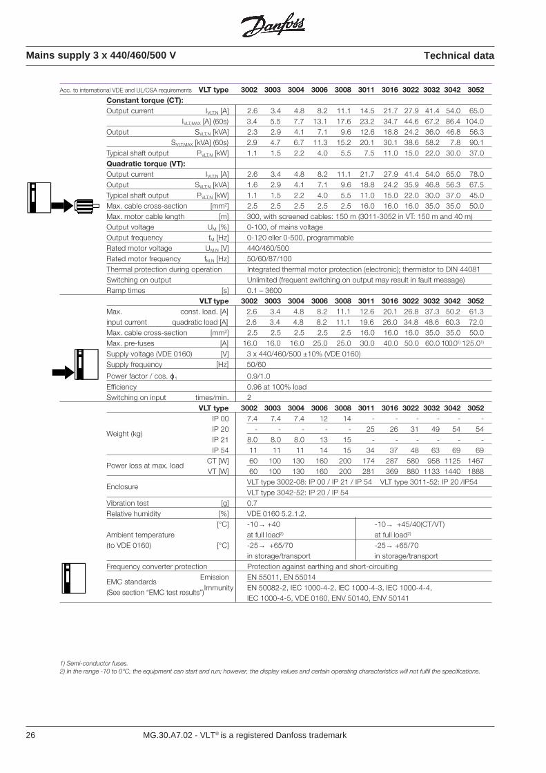
Acc. to international VDE and UL/CSA requirements VLT type 3002 3003 3004 3006 3008 3011 3016 3022 3032 3042 3052Constant torque (CT):Output current IVLT,N [A] 2.6 3.4 4.8 8.2 11.1 14.5 21.7 27.9 41.4 54.0 65.0
IVLT,MAX [A] (60s) 3.4 5.5 7.7 13.1 17.6 23.2 34.7 44.6 67.2 86.4 104.0Output SVLT,N [kVA] 2.3 2.9 4.1 7.1 9.6 12.6 18.8 24.2 36.0 46.8 56.3
SVLT,MAX [kVA] (60s) 2.9 4.7 6.7 11.3 15.2 20.1 30.1 38.6 58.2 7.8 90.1Typical shaft output PVLT,N [kW] 1.1 1.5 2.2 4.0 5.5 7.5 11.0 15.0 22.0 30.0 37.0Quadratic torque (VT):Output current IVLT,N [A] 2.6 3.4 4.8 8.2 11.1 21.7 27.9 41.4 54.0 65.0 78.0Output SVLT,N [kVA] 1.6 2.9 4.1 7.1 9.6 18.8 24.2 35.9 46.8 56.3 67.5Typical shaft output PVLT,N [kW] 1.1 1.5 2.2 4.0 5.5 11.0 15.0 22.0 30.0 37.0 45.0Max. cable cross-section [mm2] 2.5 2.5 2.5 2.5 2.5 16.0 16.0 16.0 35.0 35.0 50.0Max. motor cable length [m] 300, with screened cables: 150 m (3011-3052 in VT: 150 m and 40 m)Output voltage UM [%] 0-100, of mains voltageOutput frequency fM [Hz] 0-120 eller 0-500, programmableRated motor voltage UM,N [V] 440/460/500Rated motor frequency fM,N [Hz] 50/60/87/100Thermal protection during operation Integrated thermal motor protection (electronic); thermistor to DIN 44081Switching on output Unlimited (frequent switching on output may result in fault message)Ramp times [s] 0.1 – 3600
VLT type 3002 3003 3004 3006 3008 3011 3016 3022 3032 3042 3052Max. const. load. [A] 2.6 3.4 4.8 8.2 11.1 12.6 20.1 26.8 37.3 50.2 61.3input current quadratic load [A] 2.6 3.4 4.8 8.2 11.1 19.6 26.0 34.8 48.6 60.3 72.0Max. cable cross-section [mm2] 2.5 2.5 2.5 2.5 2.5 16.0 16.0 16.0 35.0 35.0 50.0Max. pre-fuses [A] 16.0 16.0 16.0 25.0 25.0 30.0 40.0 50.0 60.0 100.01) 125.01)
Supply voltage (VDE 0160) [V] 3 x 440/460/500 ±10% (VDE 0160)Supply frequency [Hz] 50/60
Power factor / cos. ϕ1 0.9/1.0Efficiency 0.96 at 100% loadSwitching on input times/min. 2
VLT type 3002 3003 3004 3006 3008 3011 3016 3022 3032 3042 3052
Weight (kg)
IP 00 7.4 7.4 7.4 12 14 - - - - - -IP 20 - - - - - 25 26 31 49 54 54IP 21 8.0 8.0 8.0 13 15 - - - - - -IP 54 11 11 11 14 15 34 37 48 63 69 69
Power loss at max. loadCT [W] 60 100 130 160 200 174 287 580 958 1125 1467VT [W] 60 100 130 160 200 281 369 880 1133 1440 1888
EnclosureVLT type 3002-08: IP 00 / IP 21 / IP 54 VLT type 3011-52: IP 20 /IP54VLT type 3042-52: IP 20 / IP 54
Vibration test [g] 0.7Relative humidity [%] VDE 0160 5.2.1.2.
[°C] -10→ +40 -10→ +45/40(CT/VT)Ambient temperature at full load2) at full load2)
(to VDE 0160) [°C] -25→ +65/70 -25→ +65/70in storage/transport in storage/transport
Frequency converter protection Protection against earthing and short-circuiting
EMC standardsEmission EN 55011, EN 55014
(See section “EMC test results”)Immunity EN 50082-2, IEC 1000-4-2, IEC 1000-4-3, IEC 1000-4-4,
IEC 1000-4-5, VDE 0160, ENV 50140, ENV 50141
1) Semi-conductor fuses.2) In the range -10 to 0°C, the equipment can start and run; however, the display values and certain operating characteristics will not fulfil the specifications.
27MG.30.A7.02 - VLT® is a registered Danfoss trademark
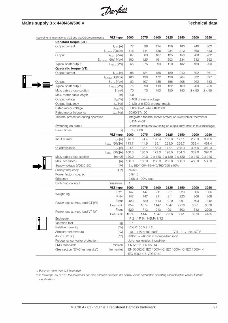
Mains supply 3 x 440/460/500 V Technical data
According to international VDE and UL/CSA requirements VLT type 3060 3075 3100 3125 3150 3200 3250Constant torque (CT):Output current IVLT,N [A] 77 96 124 156 180 240 302
IVLT,MAX [A](60s) 116 144 186 234 270 360 453Output SVLT,N [kVA] 67 83 107 135 156 208 262
SVLT,MAX (60s) [kVA] 100 125 161 203 234 312 392Typical shaft output PVLT,N [kW] 55 75 90 110 132 160 200Quadratic torque (VT):Output current IVLT,N [A] 96 124 156 180 240 302 361
IVLT,MAX [A](60s) 106 136 172 198 264 332 397Output SVLT,N [kVA] 83 107 135 156 208 262 313Typical shaft output PVLT,N [kW] 75 90 110 132 160 200 250Max. cable cross-section [mm2] 70 70 150 150 150 2 x 95 2 x 95Max. motor cable length [m] 300Output voltage UM [%] 0-100 of mains voltageOutput frequency fM [Hz] 0-120 or 0-500; programmableRated motor voltage UM,N [V] 380/400/415/440/460/500Rated motor frequency fM,N [Hz] 50/60/87/100Thermal protection during operation Integrated thermal motor protection (electronic); thermistor
to DIN 44081Switching on output Unlimited (frequent switching on output may result in fault message)
Ramp times [s] 0.1 - 3600VLT type 3060 3075 3100 3125 3150 3200 3250
Input current IL,N [A] 75.8 94.4 123.4 155.3 177.1 238.9 307.6IL,MAX (60s)[A] 113.7 141.6 185.1 233.0 265.7 358.4 461.4
Quadratic load IL,N [A] 94.4 123.4 155.3 177.1 238.9 307.6 359.3IL,MAX (60s)[A] 106.0 136.0 172.0 198.0 264.0 332.0 397.0
Max. cable cross-section [mm2] 120.0 120.0 2 x 120 2 x 120 2 x 120 2 x 240 2 x 240Max. pre-fuses1) [A] 150.0 150.0 250.0 250.0 300.0 450.0 500.0Supply voltage (VDE 0160) [V] 3 x 380/400/415/440/460/500 ±10%Supply frequency [Hz] 50/60Power factor / cos. ϕ1 0.9/1.0Efficiency 0.96 at 100% loadSwitching on input times/min. 1
VLT type 3060 3075 3100 3125 3150 3200 3250
Weight (kg)IP 21 147 147 211 211 220 306 306IP 54 147 147 211 211 220 306 306
Power loss at max. load CT [W]Front 423 529 713 910 1091 1503 1812
Heat sink 859 1074 1447 1847 2216 3051 3679
Power loss at max. load VT [W]Front 529 713 910 1091 1503 1812 2209
Heat sink 1074 1447 1847 2216 3051 3679 4485Enclosure IP 21 / IP 54, NEMA 1/12Vibration test [g] 0.7Relative humidity [%] VDE 0160 5.2.1.2.Ambient temperature [°C] -10→ +40 at full load2) (VT) -10→ +45 (CT)2)
(to VDE 0160) [°C] -30/25→ +65/70 in storage/transportFrequency converter protection Jord- og kortslutningssikkerEMC standards Emission EN 55011, EN 55014(See section “EMC test results”) Immunitet EN 50082-2, IEC 1000-4-2, IEC 1000-4-3, IEC 1000-4-4,
IEC 1000-4-5 VDE 0160
1) Bussman rapid type JJS integrated.
2) In the range -10 to 0°C, the equipment can start and run; however, the display values and certain operating characteristics will not fulfil the
specifications.
28 MG.30.A7.02 - VLT® is a registered Danfoss trademark
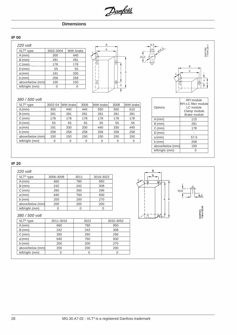
VLT® type 3002-3004 With brakeA (mm) 300 440B (mm) 281 281C (mm) 178 178D (mm) 55 55a (mm) 191 330b (mm) 258 258above/below (mm) 150 150left/right (mm) 0 0
Dimensions
IP 00
220 volt
RFI moduleRFI-LC filter module
Options LC moduleClamp moduleBrake module
A (mm) 115B (mm) 281C (mm) 178D (mm) -a (mm) 57.5b (mm) 258above/below (mm) 150left/right (mm) 0
VLT® type 3011-3016 3022 3032-3052A (mm) 660 780 950B (mm) 242 242 308C (mm) 260 260 296a (mm) 640 760 930b (mm) 200 200 270above/below (mm) 200 200 200left/right (mm) 0 0 0
IP 20
220 volt
380 / 500 volt
VLT® type 3006-3008 3011 3016-3022A (mm) 660 780 950B (mm) 242 242 308C (mm) 260 260 296a (mm) 640 760 930b (mm) 200 200 270above/below (mm) 200 200 200left/right (mm) 0 0 0
VLT® type 3002-04 With brake 3006 With brake 3008 With brakeA (mm) 300 440 440 550 500 610B (mm) 281 281 281 281 281 281C (mm) 178 178 178 178 178 178D (mm) 55 55 55 55 55 55a (mm) 191 330 330 440 330 440b (mm) 258 258 258 258 258 258above/below (mm) 150 150 150 150 150 150left/right (mm) 0 0 0 0 0 0
380 / 500 volt
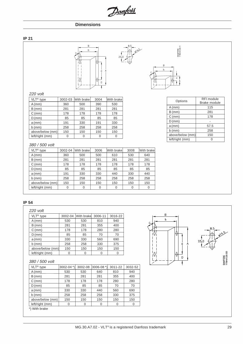
29MG.30.A7.02 - VLT® is a registered Danfoss trademark
Dimensions
IP 21
VLT® type 3002-04 With brake 3006 With brake 3008 With brakeA (mm) 360 500 500 610 530 640B (mm) 281 281 281 281 281 281C (mm) 178 178 178 178 178 178D (mm) 85 85 85 85 85 85a (mm) 191 330 330 440 330 440b (mm) 258 258 258 258 258 258above/below (mm) 150 150 150 150 150 150left/right (mm) 0 0 0 0 0 0
VLT® type 3002-03 With brake 3004 With brakeA (mm) 360 500 390 530B (mm) 281 281 281 281C (mm) 178 178 178 178D (mm) 85 85 85 85a (mm) 191 330 191 330b (mm) 258 258 258 258above/below (mm) 150 150 150 150left/right (mm) 0 0 0 0
380 / 500 volt
220 voltRFI module
Brake moduleA (mm) 115B (mm) 281C (mm) 178D (mm) -a (mm) 57.5b (mm) 258above/below (mm) 150left/right (mm) 0
Options
IP 54
VLT® type 3002-04 *) 3002-08 3006-08 *) 3011-22 3032-52A (mm) 530 530 640 810 940B (mm) 281 281 281 355 400C (mm) 178 178 178 280 280D (mm) 85 85 85 70 70a (mm) 330 330 440 560 690b (mm) 258 258 258 330 375above/below (mm) 150 150 150 150 150left/right (mm) 0 0 0 0 0
*) With brake
380 / 500 volt
220 voltVLT® type 3002-04 With brake 3006-11 3016-22A (mm) 530 530 810 940B (mm) 281 281 355 400C (mm) 178 178 280 280D (mm) 85 85 70 70a (mm) 330 330 560 690b (mm) 258 258 330 375above/below (mm) 150 150 150 150left/right (mm) 0 0 0 0
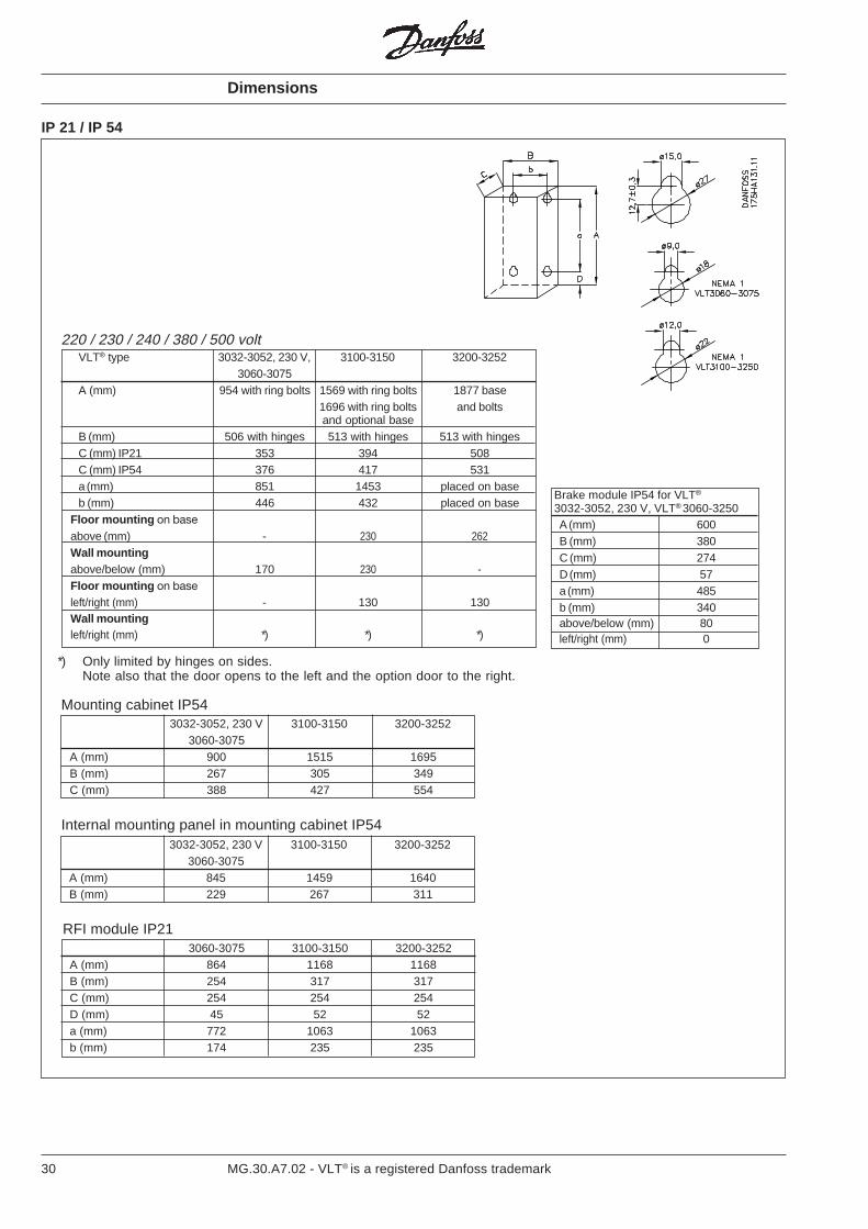
30 MG.30.A7.02 - VLT® is a registered Danfoss trademark
IP 21 / IP 54
Dimensions
RFI module IP21
220 / 230 / 240 / 380 / 500 volt
*) Only limited by hinges on sides.Note also that the door opens to the left and the option door to the right.
Mounting cabinet IP543032-3052, 230 V 3100-3150 3200-3252
3060-3075A (mm) 900 1515 1695B (mm) 267 305 349C (mm) 388 427 554
Internal mounting panel in mounting cabinet IP543032-3052, 230 V 3100-3150 3200-3252
3060-3075A (mm) 845 1459 1640B (mm) 229 267 311
3060-3075 3100-3150 3200-3252A (mm) 864 1168 1168B (mm) 254 317 317C (mm) 254 254 254D (mm) 45 52 52a (mm) 772 1063 1063b (mm) 174 235 235
VLT® type 3032-3052, 230 V, 3100-3150 3200-32523060-3075
A (mm) 954 with ring bolts 1569 with ring bolts 1877 base1696 with ring bolts and boltsand optional base
B (mm) 506 with hinges 513 with hinges 513 with hingesC (mm) IP21 353 394 508C (mm) IP54 376 417 531a (mm) 851 1453 placed on baseb (mm) 446 432 placed on base
Floor mounting on baseabove (mm) - 230 262Wall mountingabove/below (mm) 170 230 -Floor mounting on baseleft/right (mm) - 130 130Wall mountingleft/right (mm) *) *) *)
A (mm) 600B (mm) 380C (mm) 274D (mm) 57a (mm) 485b (mm) 340above/below (mm) 80left/right (mm) 0
Brake module IP54 for VLT®
3032-3052, 230 V, VLT® 3060-3250
31MG.30.A7.02 - VLT® is a registered Danfoss trademark
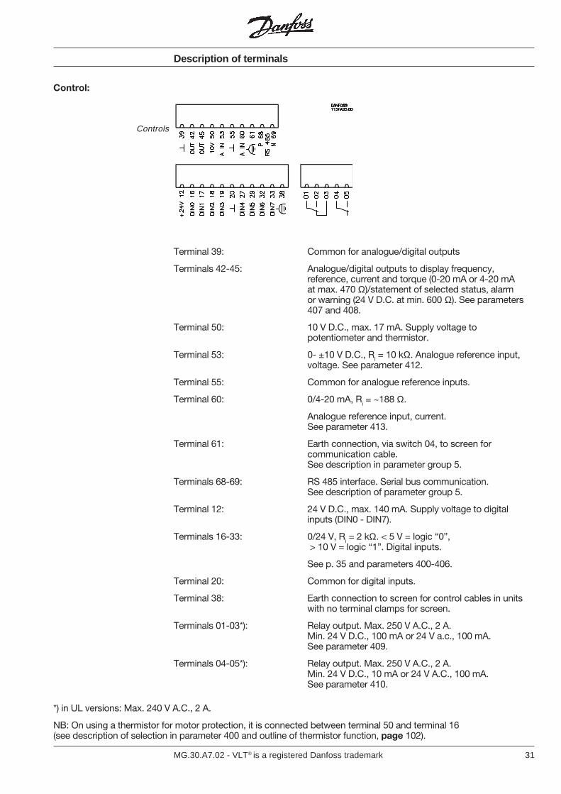
Control:
Description of terminals
Controls
Terminal 39: Common for analogue/digital outputs
Terminals 42-45: Analogue/digital outputs to display frequency,reference, current and torque (0-20 mA or 4-20 mAat max. 470 Ω)/statement of selected status, alarmor warning (24 V D.C. at min. 600 Ω). See parameters407 and 408.
Terminal 50: 10 V D.C., max. 17 mA. Supply voltage topotentiometer and thermistor.
Terminal 53: 0- ±10 V D.C., Ri = 10 kΩ. Analogue reference input,voltage. See parameter 412.
Terminal 55: Common for analogue reference inputs.
Terminal 60: 0/4-20 mA, Ri = ~188 Ω.
Analogue reference input, current.See parameter 413.
Terminal 61: Earth connection, via switch 04, to screen forcommunication cable.See description in parameter group 5.
Terminals 68-69: RS 485 interface. Serial bus communication.See description of parameter group 5.
Terminal 12: 24 V D.C., max. 140 mA. Supply voltage to digitalinputs (DIN0 - DIN7).
Terminals 16-33: 0/24 V, Ri = 2 kΩ. < 5 V = logic “0”, > 10 V = logic “1”. Digital inputs.
See p. 35 and parameters 400-406.
Terminal 20: Common for digital inputs.
Terminal 38: Earth connection to screen for control cables in unitswith no terminal clamps for screen.
Terminals 01-03*): Relay output. Max. 250 V A.C., 2 A.Min. 24 V D.C., 100 mA or 24 V a.c., 100 mA.See parameter 409.
Terminals 04-05*): Relay output. Max. 250 V A.C., 2 A.Min. 24 V D.C., 10 mA or 24 V A.C., 100 mA.See parameter 410.
*) in UL versions: Max. 240 V A.C., 2 A.
NB: On using a thermistor for motor protection, it is connected between terminal 50 and terminal 16(see description of selection in parameter 400 and outline of thermistor function, page 102).
32 MG.30.A7.02 - VLT® is a registered Danfoss trademark
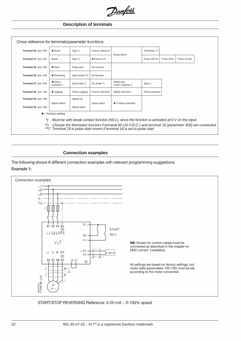
Terminal 16 / par. 400 Reset Stop *) Freeze reference Thermistor **)
Setup select
Terminal 17 / par. 401 Reset Stop *) Freeze ref. Pulse 100 Hz Pulse 1kHz Pulse 10 kHz
Terminal 18 / par. 402 Start Pulse start No function
Terminal 19 / par. 403 Reversing Start revers) No function
Terminal 27 / par. 404 Quick stop *) DC-brake *) Stop *)
Terminal 29 / par. 405 Jogging Freeze jogging Freeze reference Digital reference Ramp selection
Terminal 32 / par. 406 Speed up
Speed select Setup select 4 Setup extended
Terminal 33 / par. 406 Speed down
Description of terminals
Motorcoasting *)
Reset andmotor coasting *)
Cross reference for terminals/parameter functions.
= Factory setting.
*) Must be with break contact function (NCL), since the function is activated at 0 V on the input.**) Choose the thermistor function if terminal 50 (10 V D.C.) and terminal 16 (parameter 400) are connected.***) Terminal 19 is pulse start revers if terminal 18 is set to pulse start
Connection examples
The following shows 8 different connection examples with relevant programming suggestions
Example 1:
Connection examples
START/STOP REVERSING Reference: 4-20 mA ~ 0-100% speed
NB: Screen for control cables must beconnected as described in the chapter onEMC-correct installation.
All settings are based on factory settings, butmotor data (parameters 103-105) must be setaccording to the motor connected.
33MG.30.A7.02 - VLT® is a registered Danfoss trademark
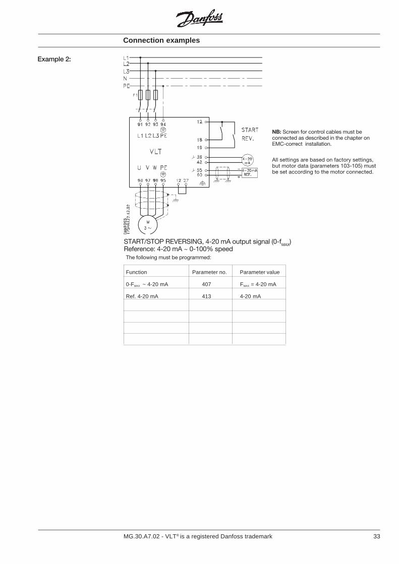
The following must be programmed:
Function Parameter no. Parameter value
0-FMAX ~ 4-20 mA 407 FMAX = 4-20 mA
Ref. 4-20 mA 413 4-20 mA
Connection examples
Example 2:
START/STOP REVERSING, 4-20 mA output signal (0-fMAX)Reference: 4-20 mA ~ 0-100% speed
NB: Screen for control cables must beconnected as described in the chapter onEMC-correct installation.
All settings are based on factory settings,but motor data (parameters 103-105) mustbe set according to the motor connected.
34 MG.30.A7.02 - VLT® is a registered Danfoss trademark
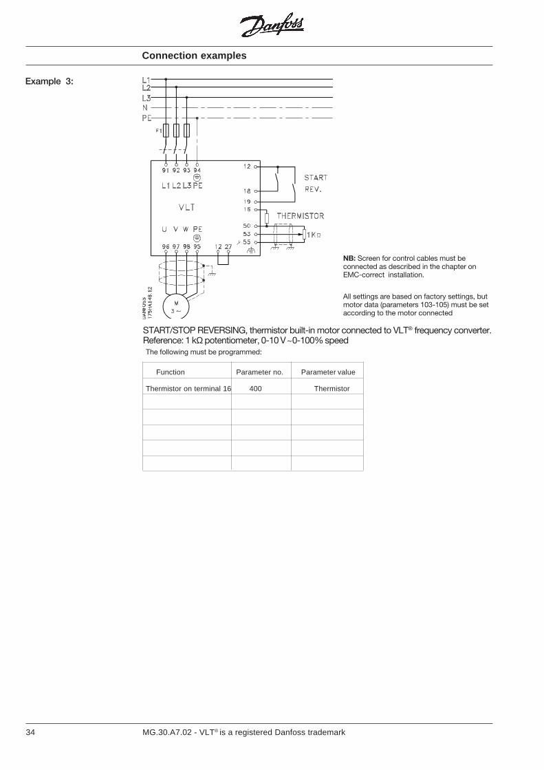
The following must be programmed:
Function Parameter no. Parameter value
Thermistor on terminal 16 400 Thermistor
Connection examples
Example 3:
START/STOP REVERSING, thermistor built-in motor connected to VLT® frequency converter.Reference: 1 kΩ potentiometer, 0-10 V ~0-100% speed
NB: Screen for control cables must beconnected as described in the chapter onEMC-correct installation.
All settings are based on factory settings, butmotor data (parameters 103-105) must be setaccording to the motor connected

35MG.30.A7.02 - VLT® is a registered Danfoss trademark
Connection examples
Example 4:
NB: Screen for control cables must beconnected as described in the chapter onEMC-correct installation.
All settings are based on factory settings, butmotor data (parameters 103-105) must be setaccording to the motor connected.
The following must be programmed:
Function Parameter no. Parameter value
STOP 404 STOP
START 402 Latched START
0-IMAX ~ 0-20 mA 407 0-IMAX
Ref. 0-10 V 412 0-10 V
3 conductor START/STOP, 0-20 mA output signal ~ (0-IMAX),0-10 V Reference: ~ 0-100% speed
36 MG.30.A7.02 - VLT® is a registered Danfoss trademark
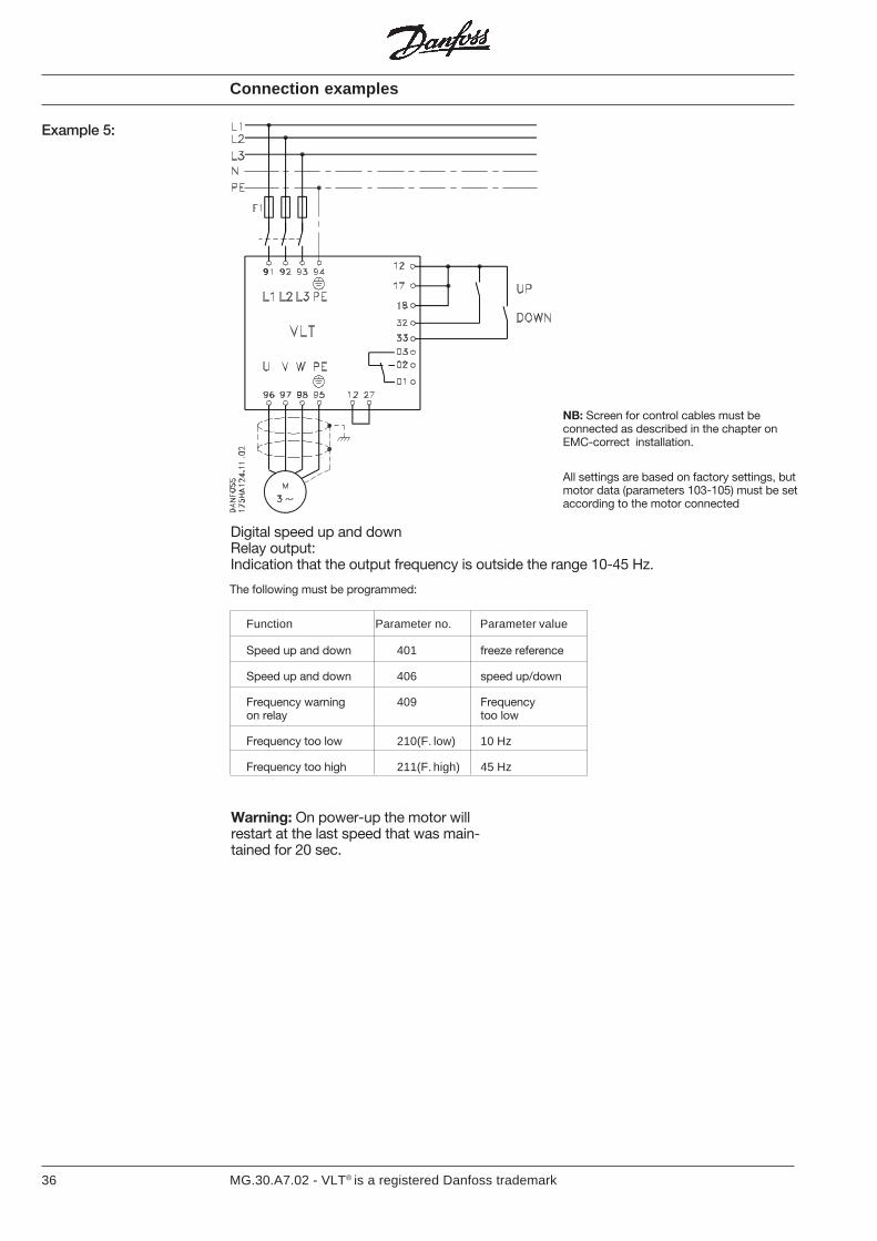
Digital speed up and downRelay output:Indication that the output frequency is outside the range 10-45 Hz.
Connection examples
Example 5:
NB: Screen for control cables must beconnected as described in the chapter onEMC-correct installation.
All settings are based on factory settings, butmotor data (parameters 103-105) must be setaccording to the motor connected
The following must be programmed:
Function Parameter no. Parameter value
Speed up and down 401 freeze reference
Speed up and down 406 speed up/down
Frequency warning 409 Frequencyon relay too low
Frequency too low 210(F. low) 10 Hz
Frequency too high 211(F. high) 45 Hz
Warning: On power-up the motor willrestart at the last speed that was main-tained for 20 sec.

37MG.30.A7.02 - VLT® is a registered Danfoss trademark
6 fixed speeds, max. speed 60 Hz1 speed = 6 Hz (10%), 2 speeds = 12 Hz (20%),3 speeds = 18 Hz (30%), 4 speeds = 24 Hz (40%),5 speeds = 42 Hz (70%), 6 speeds = 60 Hz (100%)
Connection examples
Example 6:
NB: Screen for control cables must beconnected as described in the chapter onEMC-correct installation.
All settings are based on factory settings, butmotor data (parameters 103-105) must be setaccording to the motor connected
The following must be programmed:
Function Parameter no. Parameter value
Setup selection 001 multi setup
Setup selection 400 setup selection
Speed selection 406 digital ref. selection
Select setup 1
Max. frequency 202 60 Hz
Digital reference 1 205 10%
Digital reference 2 206 20%
Digital reference 3 207 30%
Digital reference 4 208 40%
Select setup 2
Max. frequency 202 60 Hz
Digital reference 5 205 70%
Digital reference 6 205 100%

38 MG.30.A7.02 - VLT® is a registered Danfoss trademark
Use of the VLT® frequency converter’s internal PID regulatorwith internal set-point (digital reference = 50%)Feedback 0-10 bar ~ 4-20 mAMin. speed = 10 HzMax. speed = 50 Hz
Function Parameter no. Parameter value
Activation ofPID regulator 101 closed loop
Internal setpoint 205 50 %
Feedback type 114 current
Current signal 413 4-20 mA
Min. speed 201 10 Hz
Max. speed 202 50 Hz
Regulator range 120 Depends onapplication
Proportional 121 Depends onamplification application
Integration time 122 Depends onapplication
Differentiation time 123 Depends onapplication
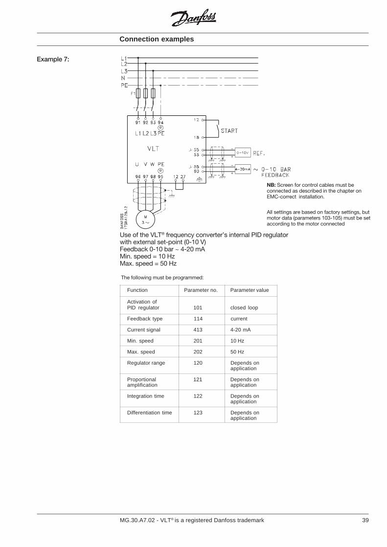
Example 7:
NB: Screen for control cables must beconnected as described in the chapter onEMC-correct installation.
All settings are based on factory settings, butmotor data (parameters 103-105) must be setaccording to the motor connected
The following must be programmed:
Connection examples
39MG.30.A7.02 - VLT® is a registered Danfoss trademark
Function Parameter no. Parameter value
Activation ofPID regulator 101 closed loop
Feedback type 114 current
Current signal 413 4-20 mA
Min. speed 201 10 Hz
Max. speed 202 50 Hz
Regulator range 120 Depends onapplication
Proportional 121 Depends onamplification application
Integration time 122 Depends onapplication
Differentiation time 123 Depends onapplication
Use of the VLT® frequency converter’s internal PID regulatorwith external set-point (0-10 V)Feedback 0-10 bar ~ 4-20 mAMin. speed = 10 HzMax. speed = 50 Hz
Example 7:
NB: Screen for control cables must beconnected as described in the chapter onEMC-correct installation.
All settings are based on factory settings, butmotor data (parameters 103-105) must be setaccording to the motor connected
Connection examples
The following must be programmed:
40 MG.30.A7.02 - VLT® is a registered Danfoss trademark
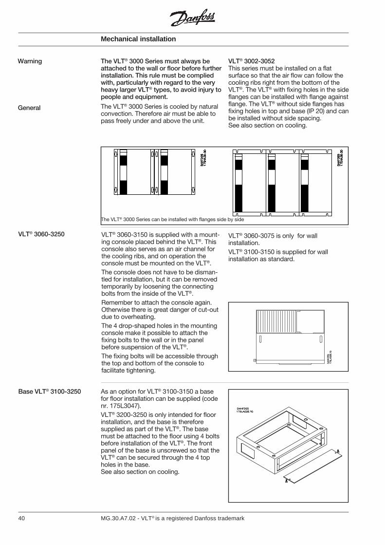
Warning The VLT® 3000 Series must always beattached to the wall or floor before furtherinstallation. This rule must be compliedwith, particularly with regard to the veryheavy larger VLT® types, to avoid injury topeople and equipment.
As an option for VLT® 3100-3150 a basefor floor installation can be supplied (codenr. 175L3047).VLT® 3200-3250 is only intended for floorinstallation, and the base is thereforesupplied as part of the VLT®. The basemust be attached to the floor using 4 boltsbefore installation of the VLT®. The frontpanel of the base is unscrewed so that theVLT® can be secured through the 4 topholes in the base.See also section on cooling.
Base VLT® 3100-3250
VLT® 3060-3150 is supplied with a mount-ing console placed behind the VLT®. Thisconsole also serves as an air channel forthe cooling ribs, and on operation theconsole must be mounted on the VLT®.The console does not have to be disman-tled for installation, but it can be removedtemporarily by loosening the connectingbolts from the inside of the VLT®.Remember to attach the console again.Otherwise there is great danger of cut-outdue to overheating.The 4 drop-shaped holes in the mountingconsole make it possible to attach thefixing bolts to the wall or in the panelbefore suspension of the VLT®.The fixing bolts will be accessible throughthe top and bottom of the console tofacilitate tightening.
VLT® 3060-3075 is only for wallinstallation.VLT® 3100-3150 is supplied for wallinstallation as standard.
The VLT® 3000 Series can be installed with flanges side by side
VLT® 3060-3250
Mechanical installation
The VLT® 3000 Series is cooled by naturalconvection. Therefore air must be able topass freely under and above the unit.
VLT® 3002-3052This series must be installed on a flatsurface so that the air flow can follow thecooling ribs right from the bottom of theVLT®. The VLT® with fixing holes in the sideflanges can be installed with flange againstflange. The VLT® without side flanges hasfixing holes in top and base (IP 20) and canbe installed without side spacing.See also section on cooling.
General

41MG.30.A7.02 - VLT® is a registered Danfoss trademark
Mechanical installation
VLT® type 3100-3150 3200-3250
A [mm] 79 102
B [mm] 153 178
a [mm] 23 10
b [mm] 191 287
Base for mounting console and IP 54, RFI module:
VLT® type 3100-3150 3200-3250
A [mm] 76 100
B [mm] 151 176
a [mm] 23 10
b [mm] 191 287
Base:
Base seen from side:
previous versions of VLT® 3100-3250units, but never use the previous basedesign for the VLT® units with the remov-able base plate.
The bases for VLT® and options have beenupdated to match VLT® 3100-3250 withthe removable plate in the bottom. Notethat the ventilation slots have been re-placed with two apertures in the sides.When a base is also used for the mountingconsole and RFI in IP 54 enclosure,remember to match up the ventilationapertures.The new base design can be used with
VLT® type 3100-3150 3200-3250
A [mm] 127 127
B [mm] 495 495
C [mm] 361 495
D [mm] 4 x 12.7 4 x 12.7
b [mm] 445 445
c [mm] 310 445
The drawing shows the base and itsdimensions.
42 MG.30.A7.02 - VLT® is a registered Danfoss trademark
Mechanical installation
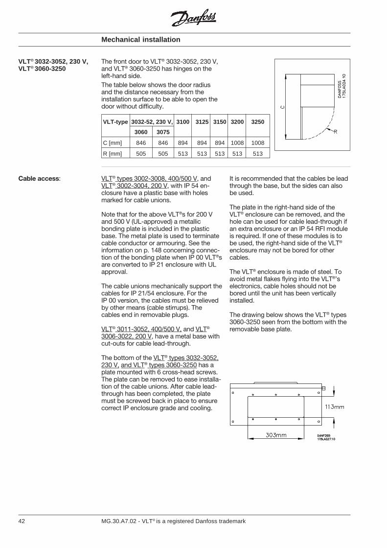
The front door to VLT® 3032-3052, 230 V,and VLT® 3060-3250 has hinges on theleft-hand side.The table below shows the door radiusand the distance necessary from theinstallation surface to be able to open thedoor without difficulty.
VLT® 3032-3052, 230 V,VLT® 3060-3250
VLT-type 3032-52, 230 V, 3100 3125 3150 3200 3250
3060 3075
C [mm] 846 846 894 894 894 1008 1008
R [mm] 505 505 513 513 513 513 513
It is recommended that the cables be leadthrough the base, but the sides can alsobe used.
The plate in the right-hand side of theVLT® enclosure can be removed, and thehole can be used for cable lead-through ifan extra enclosure or an IP 54 RFI moduleis required. If one of these modules is tobe used, the right-hand side of the VLT®
enclosure may not be bored for othercables.
The VLT® enclosure is made of steel. Toavoid metal flakes flying into the VLT®’selectronics, cable holes should not bebored until the unit has been verticallyinstalled.
The drawing below shows the VLT® types3060-3250 seen from the bottom with theremovable base plate.
VLT® types 3002-3008, 400/500 V, andVLT® 3002-3004, 200 V, with IP 54 en-closure have a plastic base with holesmarked for cable unions.
Note that for the above VLT®s for 200 Vand 500 V (UL-approved) a metallicbonding plate is included in the plasticbase. The metal plate is used to terminatecable conductor or armouring. See theinformation on p. 148 concerning connec-tion of the bonding plate when IP 00 VLT®sare converted to IP 21 enclosure with ULapproval.
The cable unions mechanically support thecables for IP 21/54 enclosure. For theIP 00 version, the cables must be relievedby other means (cable stirrups). Thecables end in removable plugs.
VLT® 3011-3052, 400/500 V, and VLT®
3006-3022, 200 V, have a metal base withcut-outs for cable lead-through.
The bottom of the VLT® types 3032-3052,230 V, and VLT® types 3060-3250 has aplate mounted with 6 cross-head screws.The plate can be removed to ease installa-tion of the cable unions. After cable lead-through has been completed, the platemust be screwed back in place to ensurecorrect IP enclosure grade and cooling.
Cable access:
43MG.30.A7.02 - VLT® is a registered Danfoss trademark
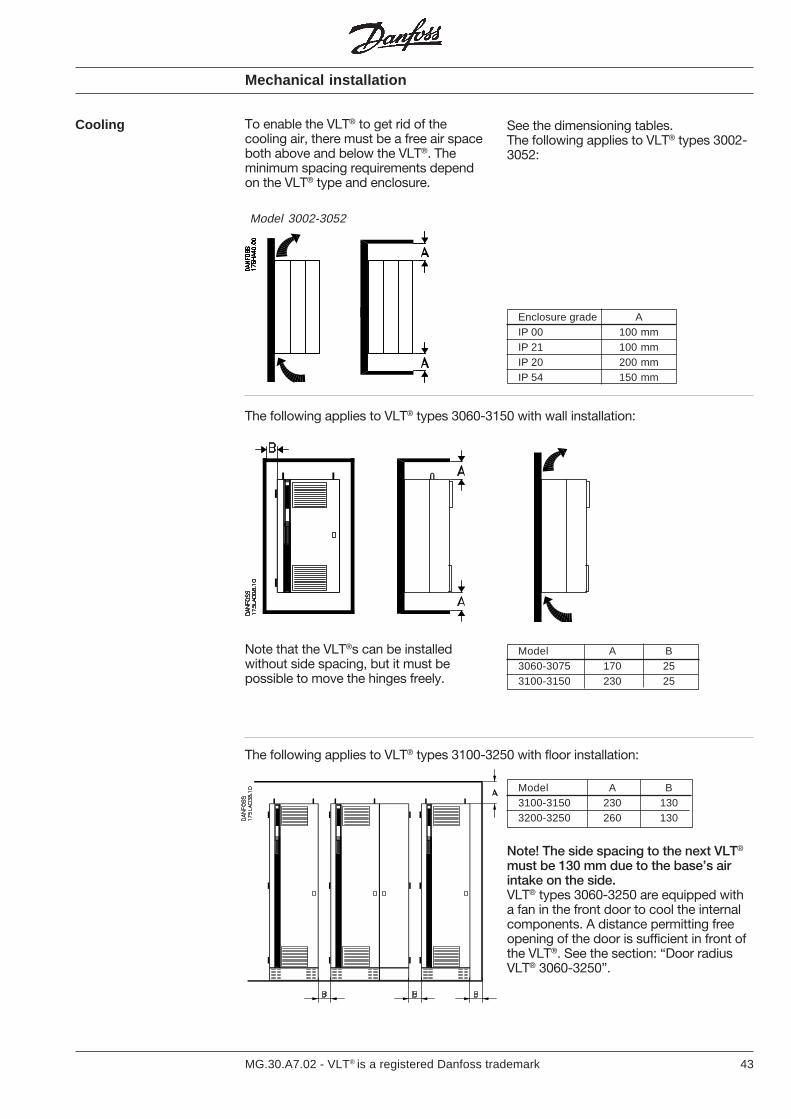
To enable the VLT® to get rid of thecooling air, there must be a free air spaceboth above and below the VLT®. Theminimum spacing requirements dependon the VLT® type and enclosure.
Cooling See the dimensioning tables.The following applies to VLT® types 3002-3052:
The following applies to VLT® types 3060-3150 with wall installation:
Enclosure grade AIP 00 100 mmIP 21 100 mmIP 20 200 mmIP 54 150 mm
Model 3002-3052
Note that the VLT®s can be installedwithout side spacing, but it must bepossible to move the hinges freely.
The following applies to VLT® types 3100-3250 with floor installation:
Model A B3100-3150 230 1303200-3250 260 130
Note! The side spacing to the next VLT®
must be 130 mm due to the base’s airintake on the side.VLT® types 3060-3250 are equipped witha fan in the front door to cool the internalcomponents. A distance permitting freeopening of the door is sufficient in front ofthe VLT®. See the section: “Door radiusVLT® 3060-3250”.
Mechanical installation
Model A B3060-3075 170 253100-3150 230 25
44 MG.30.A7.02 - VLT® is a registered Danfoss trademark
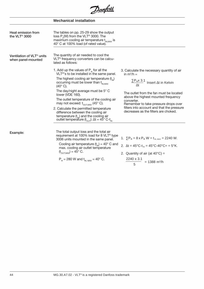
The tables on pp. 25-29 show the outputloss P2(W) from the VLT® 3000. Themaximum cooling air temperature tIN,MAX is40° C at 100% load (of rated value).
Mechanical installation
Heat emission fromthe VLT® 3000
1. Add up the values of PΦ for all theVLT®’s to be installed in the same panel.The highest cooling air temperature (tIN)occurring must be lower than tIN,MAX(40° C).The day/night average must be 5° Clower (VDE 160).The outlet temperature of the cooling airmay not exceed: t
OUT,MAX (45° C).
2. Calculate the permitted temperaturedifference between the cooling airtemperature (tIN) and the cooling airoutlet temperature (tOUT): ∆t = 45° C-tIN
= 1388 m3/h5
2240 x 3.1
1. ∑PΦ = 8 x PΦ W = t IN, MAX = 2240 W.
2. ∆t = 45°C-t IN = 45°C-40°C= = 5°K.
2. Quantity of air (at 40°C) =
Example:
Ventilation of VLT® unitswhen panel-mounted
The quantity of air needed to cool theVLT® frequency converters can be calcu-lated as follows:
The total output loss and the total airrequirement at 100% load for 8 VLT® type3006 units mounted in the same panel.
Cooling air temperature (tIN) = 40° C andmax. cooling air outlet temperature(tOUT,MAX) = 45° C.
PΦ = 280 W and tIN, MAX = 40° C.
3. Calculate the necessary quantity of airin m3/h =
The outlet from the fan must be locatedabove the highest mounted frequencyconverter.Remember to take pressure drops overfilters into account and that the pressuredecreases as the filters are choked.
∑PΦx 3.1∆t
Insert ∆t in Kelvin
45MG.30.A7.02 - VLT® is a registered Danfoss trademark
The VLT®’s voltage is dangerous when it isconnected to the mains supply and for upto 14 minutes after disconnection of theVLT®. Electrical installation may thereforeonly be carried out by an authorized techni-cian.
Warning Incorrect installation of the motor or VLT®
can damage equipment and causeserious injury or death. Therefore complywith the instructions in this manual, aswell as local and national safety regula-tions.
Note:It is the responsibility of the user ortechnician to ensure correct earthing andprotection according to current local andnational standards.
Pre-fuses
GeneralThe terminals for the 3-phase supply andthe motor are placed in the lowest sectionof the VLT®’s enclosure.The motor cable’s screen is connected toboth the VLT® and the motor. The VLT®
has been tested with a given length ofscreened cable and a particular cross-section. If the cross-section is increased,the capacitance leakage of the cableincreases and thereby the dischargecurrent. The length must be reduced
For VLT® types 3002-3052, external pre-fuses must be installed in the currentsupply to the frequency converter.The technical data section on pp. 23-27states correct size and dimensioning.
For VLT® types 3032-3052, 230 V, andVLT® types 3060-3250, pre-fuses areincluded in the VLT®’s mains connection.
proportionally. The electronic thermal relay(ETR) in UL-approved VLT® frequencyconverters is UL-approved for single-motor application when parameter 315 isset at trip, parameter 311 at “0 sec.” andparameter 107 programmed for themotor’s nominal current (read on themotor’s type plate).
Electrical installation
A high voltage test can be performed byshort-circuiting terminals U, V, W, L1, L2,L3, and impressing 2.5 kW D.C. for 1second between this short circuit and thechassis.After the high voltage test, the filter con-densers should be discharged using aresistor of e.g. 100 ohm, 1/4 W- 1/2 W.
The resistors is placed between +D.C. busto the chassis and -D.C. bus to the chas-sis, for a few seconds.
High voltage test
Error voltage relays, or neutral earthing,current in the discharged current.Any ELCB relays used must comply withlocal regulations.The relays must be suitable to protect 3-phase equipment with bridge rectifier andshort discharge on power-up.See also the section on discharge currentson p. 128.
Extra protection
46 MG.30.A7.02 - VLT® is a registered Danfoss trademark
Connection of VLT ®
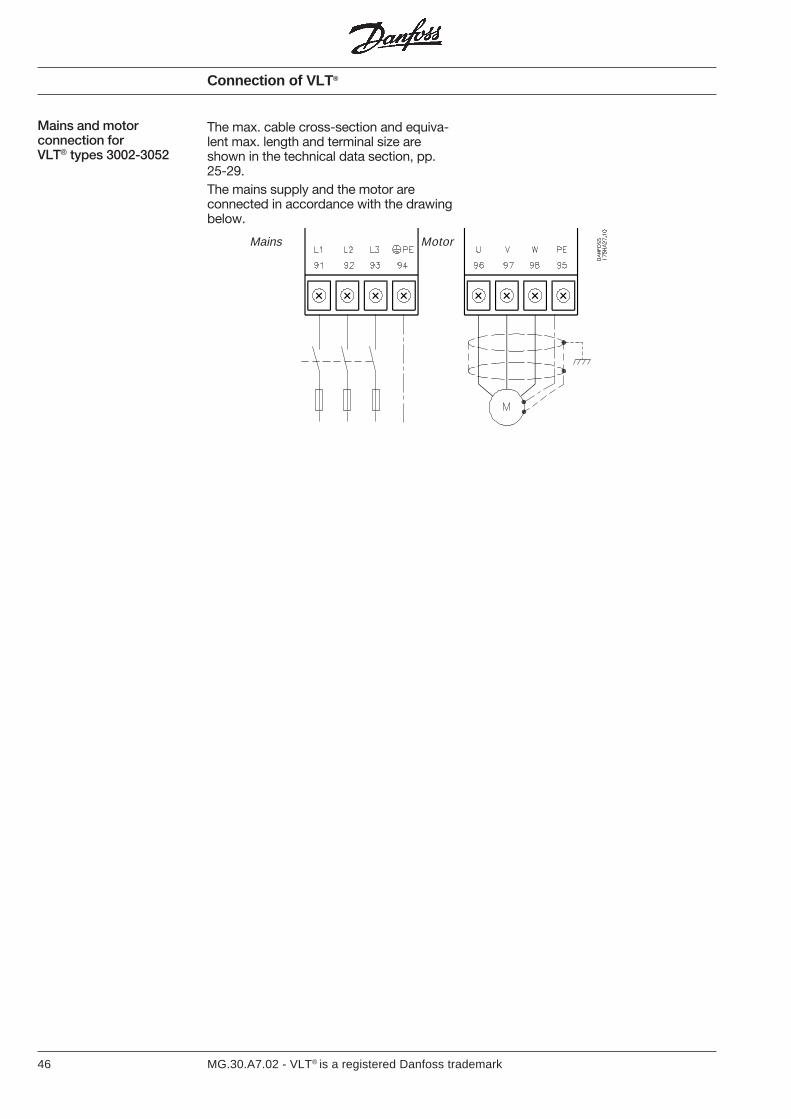
Mains and motorconnection forVLT® types 3002-3052
The max. cable cross-section and equiva-lent max. length and terminal size areshown in the technical data section, pp.25-29.The mains supply and the motor areconnected in accordance with the drawingbelow.
Mains Motor
47MG.30.A7.02 - VLT® is a registered Danfoss trademark
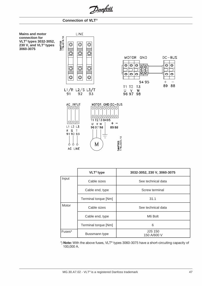
VLT® type 3032-3052, 230 V, 3060-3075
Cable sizes See technical data
Cable end, type Screw terminal
Terminal torque [Nm] 31.1
Cable sizes See technical data
Cable end, type M6 Bolt
Terminal torque [Nm] 6
Bussmann type
Motor
Input
Fuses*
*) Note: With the above fuses, VLT® types 3060-3075 have a short-circuiting capacity of 100,000 A.
Mains and motorconnection forVLT® types 3032-3052,230 V, and VLT ® types3060-3075
JJS 150150 A/600 V
Connection of VLT®

48 MG.30.A7.02 - VLT® is a registered Danfoss trademark
Motor
Input
Fuses*
VLT® type 3100 3125 3150
Cable sizes See technical data See technical data See technical data
Screw terminal Screw terminal Screw terminal
31.1 31.1 31.1
Cable sizes See technical data See technical data See technical data
M10 Bolt M10 Bolt M10 Bolt
10 10 10
Bussmann type
Cable end,type
Terminal torque[Nm]
Cable end,type
Terminal torque[Nm]
JJS 250250 A/600 V
JJS 250250 A/600 V
JJS 300300 A/600 V
*) Note: With the above fuses, VLT® types 3100-3150 have a short-circuiting capacity of 100,000 A.
Mains and motorconnection forVLT® types3100-3150
Connection of VLT ®
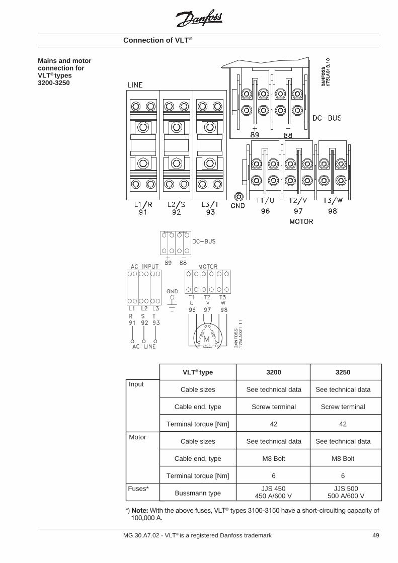
49MG.30.A7.02 - VLT® is a registered Danfoss trademark
*) Note: With the above fuses, VLT® types 3100-3150 have a short-circuiting capacity of 100,000 A.
VLT® type 3200 3250
Cable sizes See technical data See technical data
Cable end, type Screw terminal Screw terminal
Terminal torque [Nm] 42 42
Cable sizes See technical data See technical data
Cable end, type M8 Bolt M8 Bolt
Terminal torque [Nm] 6 6
Bussmann type
Motor
Input
Fuses* JJS 450450 A/600 V
JJS 500500 A/600 V
Mains and motorconnection forVLT® types3200-3250
Connection of VLT ®

50 MG.30.A7.02 - VLT® is a registered Danfoss trademark
With the VLT® 3000 Series, all types of3-phase asynchronous standard motorscan be used.
In general, small motors (220/380 V, ∆/ )are star-connected. Large motors aredelta-connected (380/660 V, ∆/ ).
Motor connection
The factory setting will give clockwiserotation when the output of the VLT® 3000Series is connected as follows:
Terminal 96 connected with U phaseTerminal 97 connected with V phaseTerminal 98 connected with W phase
The rotation direction can be changed byswapping the two motor cable phases.
With the VLT® 3000 Series controls, therotation direction can also be changedusing the “reverse” function.
VLT® 3000 Series can control severalmotors connected in parallel. If the motorspeeds must be different, motors ofdifferent rated speeds must be applied.The motor speed can be changed simul-taneously and the ratio between the ratedmotor speeds is maintained in the wholerange.
The total current consumed by the motorsmay not exceed the maximum rated outputcurrent IVLT,N of the VLT® 3000 Series.
If motor sizes deviate considerably, prob-lems may arise during start and at lowspeed. This is due to the fact that smallmotors have a relatively high ohmic resist-ance in the stator, and therefore theyrequire more start voltage during start andat low speed.
In systems with parallel motor operation,the internal overcurrent protection cannotbe used as motor protection for the indi-vidual motor, since the output current mustbe programmed for the total motor current.Additional motor protection should there-fore be used, e.g. thermistors in eachmotor (or individual thermal relay).
Direction of rotation
Parallel connectionof motors
Connection of motor
Y
Y
51MG.30.A7.02 - VLT® is a registered Danfoss trademark
EMC installation
The purpose of CE-labelling is to avoidtechnical obstacles to trade within EFTAand the EU. The EU has introduced theCE-label as a simple way of showingwhether a product complies with the
relevant EU directives. The CE-label saysnothing about the quality or specificationsof a product. Three EU directives relate tofrequency converters:
The machine directive (89/392/EEC)All machines with critical, moving parts arecomprised by the machine directive whichcame into force on 1 January 1995. Sincea frequency converter is largely electricalby function, it does not fall under the
machine directive. However, if a frequencyconverter is supplied for use in a machine,we provide information about the safetyaspects relating to the frequency con-verter. We do that by means of a manufac-turer’s declaration.
The low-voltage directive (73/23/EEC)Frequency converters must be CE-labelledin accordance with the low-voltage direc-tive, which will come into force on1 January 1997.
This directive applies to all electricalequipment and appliances used in thevoltage range of 50-1000 VAC and 75-1500 VDC.
The EMC directive (89/336/EEC)EMC is short for electromagnetic compat-ibility. The presence of electromagneticcompatibility means that the mutualinterference between different compo-nents/appliances is so small that the
functioning of the appliances is not af-fected. The EMC directive comes intoforce on 1 January 1996. The directivedistinguishes between components,appliances, systems and installations.
The EU “Guidelines on the Application ofCouncil Directive 89/336/EEC” outline fourtypical situations of using a frequencyconverter. For each of these situations,explanations are offered as to whether thesituation in question is covered by theEMC directive and must be CE-labelled.
1. The frequency converter is sold directto the end-user. This applies for exam-ple if the frequency converter is sold toa DIY-market. The end-user is not anexpert. He installs the frequencyconverter himself, e.g. for controlling ahobby machine or a domestic appli-ance. This frequency converter mustbe CE-labelled in accordance with theEMC directive.
2. The frequency converter is intended foruse in a complete product. It is solde.g. to a professional machine builderwho has the technical knowledge ittakes to install the frequency convertercorrectly. The frequency converterneed not be CE-labelled in accordancewith the EMC directive. Instead, thefrequency converter manufacturer mustbe provide detailed guidelines on howto carry out an EMC-correct installa-tion.
3. The frequency converter is intended foruse in an installation built up on the siteof use by a professional. This could bee.g. a complete installation for manu-facturing purposes or for the genera-tion of heat/ventilation. The installationis planned and made by a professionalinstallation builder. The completesystem is not to be CE-labelled inaccordance with the EMC directive.The system must comply with the basicrequirements contained in the directive.This is ensured by using components,appliances and systems which are CE-labelled in accordance with the EMCdirective.
4. The frequency converter is sold as partof a complete system, such as an air-conditioning system. The completesystem must be CE-labelled in accord-ance with the EMC directive.
What is CE-labelling?
52 MG.30.A7.02 - VLT® is a registered Danfoss trademark
EMC installation
Danfoss VLT ®
frequency converterand CE-labelling
CE-labelling is a positive feature whenused for it original purpose, i.e. to facilitatetrade within the EU and EFTA.
However, CE-labelling may cover manydifferent specifications. This means that ithas to be checked what a given CE-labelspecifically covers.
The specifications covered can in fact bewidely different. That is why the CE-labelcan give installers a false feeling of secu-rity when using a frequency converter as acomponent in a system or an appliance.
We CE-label our VLT frequency convert-ers in accordance with the low-voltagedirective. This means that as long as thefrequency converter is installed correctly,we guarantee that it complies with thelow-voltage directive. We issue a declara-tion of conformity confirming that our CE-label complies with the low-voltage direc-tive.
The CE-label also applies to the EMCdirective on the condition that the EMC-correct installation and filtering in-structions in the manual have beenfollowed. On this basis a conformitydeclaration is issued in accordance withthe EMC directive.
To help ensure that your installation isEMC-correct, the manual provides de-tailed instructions for installation. Further-more, we specify which norms that arecomplied with by our products.
We offer the filters that meet the specifica-tions and can gladly provide other types ofassistance that can help you obtain thebest possible EMC result.
53MG.30.A7.02 - VLT® is a registered Danfoss trademark
EMC installation
In support of our claim that the VLT®
frequency converter complies with theprotection requirements for emission andimmunity under EMC directive 89/336/EEC, a Technical Construction File (TCF)has been prepared for each model. Sucha file defines the EMC requirements andthe measurements made in accordancewith harmonised EMC standards in aPower Drive System (PDS) that consists ofa VLT® frequency converter, a controlcable and the controls (control box), motorcable and motor plus any options added.The Technical Construction File is pre-pared on this basis in cooperation with anauthorised EMC laboratory (CompetentBody).
In most cases the VLT frequency con-verter is used by professionals of the tradeas a complex component forming part of alarger appliance, system or installation. Itmust be noted that the responsibility forthe final EMC properties of the appliance,system or installation rests with the fitter.As an aid to the fitter, Danfoss has pre-pared EMC installation guidelines for thePower Drive System. The standards andtesting levels stated for the Power DriveSystem are complied with, provided thatthe EMC-correct installation guidelines areapplied.
The following basic issues need to beconsidered when installing a frequencyconverter, so as to obtain electromagneticcompatibility (EMC).
Safety earthing:Please note: The frequency converter hasa high leakage current and must beearthed appropriately for safety reasons.Apply local safety regulations.
High-frequency earthing:Keep the earth wire connections as shortas possible.Connect the different earth systems at thelowest possible conductor impedance.The lowest possible conductor impedanceis obtained by keeping the conductor asshort as possible and by using the great-est possible surface area. A flat conductor,
for example, has a lower HF impedancethan a round conductor for the sameconductor square value.If more than one appliance is installed incabinets, the cabinet rear plate, whichmust be made of metal, should be used asa common earth reference plate. Themetal cabinets of the different appliancesare mounted on the cabinet rear plateusing the lowest possible HF impedance.This avoids having different HF voltagesfor the individual appliances and avoidsthe risk of radio interference currentsrunning in connection cables that may beused between the appliances.In order to obtain a low HF impedance,use the fastening bolts of the appliancesas HF connection to the rear plate. It isnecessary to remove insulating paint orsimilar from the fastening points.
The control cable and the filtered mainscable should be installed separately fromthe motor and brake cables to preventinterference coupling. Normally, a distanceof 20 cm will be sufficient, but it is recom-mended to keep the greatest possibledistance wherever possible, especiallywhere cables are installed in parallel over asubstantial distance. (Seperation shouldincrease in proportion).
With respect to sensitive signal cables,such as telephone cables and data cables,the greatest possible distance is recom-mended with a minimum of 1 m per 5 m ofpower cable (mains, motor and brakecable). It must be pointed out that the
necessary distance depends on the sensi-tivity of the installation and the signalcables, and that therefore no precisevalues can be stated.
If cable clamps are used, sensitive signalcables are not to be placed in the samecable clamps as the motor cable or brakecable.
If signal cables are to cross power cables,this should be done at an angle of 90degrees.
Remember that all noisy in- or outgoingcables to/from a cabinet should bescreened or filtered.
Cables
Earthing
Compliance with EMCdirective 89/336/EEC
Screened cables The screen must be a low HF-impedancescreem. This is ensured by using a braidedscreen of cobber, aluminium or iron.
Screen armour intended for mechanicalprotection, for example, is not suitable foran EMC-correct installation.
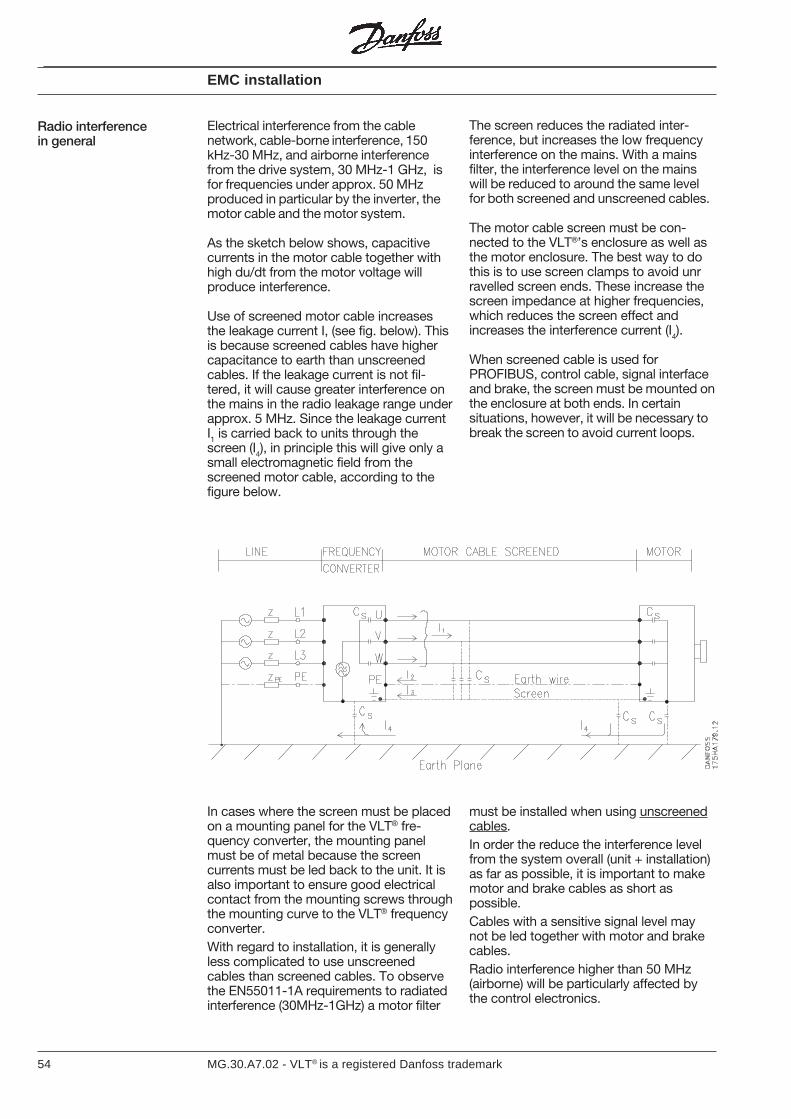
54 MG.30.A7.02 - VLT® is a registered Danfoss trademark
Electrical interference from the cablenetwork, cable-borne interference, 150kHz-30 MHz, and airborne interferencefrom the drive system, 30 MHz-1 GHz, isfor frequencies under approx. 50 MHzproduced in particular by the inverter, themotor cable and the motor system.
As the sketch below shows, capacitivecurrents in the motor cable together withhigh du/dt from the motor voltage willproduce interference.
Use of screened motor cable increasesthe leakage current I, (see fig. below). Thisis because screened cables have highercapacitance to earth than unscreenedcables. If the leakage current is not fil-tered, it will cause greater interference onthe mains in the radio leakage range underapprox. 5 MHz. Since the leakage currentI1 is carried back to units through thescreen (I4), in principle this will give only asmall electromagnetic field from thescreened motor cable, according to thefigure below.
EMC installation
Radio interferencein general
The screen reduces the radiated inter-ference, but increases the low frequencyinterference on the mains. With a mainsfilter, the interference level on the mainswill be reduced to around the same levelfor both screened and unscreened cables.
The motor cable screen must be con-nected to the VLT®’s enclosure as well asthe motor enclosure. The best way to dothis is to use screen clamps to avoid unrravelled screen ends. These increase thescreen impedance at higher frequencies,which reduces the screen effect andincreases the interference current (I
4).
When screened cable is used forPROFIBUS, control cable, signal interfaceand brake, the screen must be mounted onthe enclosure at both ends. In certainsituations, however, it will be necessary tobreak the screen to avoid current loops.
In cases where the screen must be placedon a mounting panel for the VLT® fre-quency converter, the mounting panelmust be of metal because the screencurrents must be led back to the unit. It isalso important to ensure good electricalcontact from the mounting screws throughthe mounting curve to the VLT® frequencyconverter.With regard to installation, it is generallyless complicated to use unscreenedcables than screened cables. To observethe EN55011-1A requirements to radiatedinterference (30MHz-1GHz) a motor filter
must be installed when using unscreenedcables.In order the reduce the interference levelfrom the system overall (unit + installation)as far as possible, it is important to makemotor and brake cables as short aspossible.Cables with a sensitive signal level maynot be led together with motor and brakecables.Radio interference higher than 50 MHz(airborne) will be particularly affected bythe control electronics.

55MG.30.A7.02 - VLT® is a registered Danfoss trademark
Instructions forinstallation
FilteringElectrical interference from the cablenetwork - cable-borne as well as air-borne- can be prevented by using the correctfilters. The filters or equivalent stated inthe product programme must be installed,and when re-mounting, the filterinstallation instructions are to beobserved.VLT® 3002-3052All models have filters for integration into/mounting on the appliance itself. Some
models offer the feature of ordering theappliance with the filter already integrated.See the product range. In the case ofsubsequent installation, the instructions forinstallation of the filter must be compliedwith (see also the instructions for installa-tion, item F).
VLT® 3060-3250The filter is supplied as an IP54 option oran IP20 option that cannot be integrated inthe appliance itself, but can be bolteddirectly on the side.
Mechanical installation VLT® 3002-3008, IP00/IP21 enclosureVLT® 3002-3008, IP00/IP21/IP54enclosure with brake:VLT® 3002 - VLT® 3008, IP00/IP21 enclo-sure and VLT® 3002-3008, IP00/IP21/IP54enclosure with brake must always be in-stalled against a conductive rear plate.
Install the metal cabinet of the VLT®
frequency converter up against the rearplate. The rear plate must be electricallyconductive and act as a common HF earthreference for the VLT® frequency con-verter, the RFI/brake module and anybrake cables used. The VLT® frequencyconverter and the RFI/brake module mustbe installed with the lowest possible HFimpedance to the rear plate. This can bestbe done through the fastening bolts for theenclosure (see instructions for installation,pp. 57-59, item A). Since the aluminiumenclosure of the appliances is anodisedand thus electrically insulating, toothed(serrated) washers should be used topenetrate the anodisation - or the ano-dised surface has to be removed. Remem-ber also to remove any varnish or paintfrom the rear plate.
VLT® 3002-3008, IP54 enclosure withoutbrakeVLT® 3011-3052, IP20/IP54 enclosure:Appliances can be installed on an electri-cally conductive or a non-conductive rearplate, since the RFI filter can be or isintegrated and the screen from controlcables, motor cable and brake cable (notVLT® 3002-3008) can be terminated in theappliances (see instructions for installation,pp. 57-59, items B, C and D).If an electrically conductive rear plate isused, the VLT® frequency converter mustbe installed with the lowest possible HFimpedance to the rear plate, and theinstructions for installation, pp. 57-59,items A, B, C, D and E, must be compliedwith.
If a non-conductive rear plate is used (i.e.in the case of installation directly against abrick wall), use the instructions for installa-tion, pp. 57-59, items B, C and D.
VLT® 3032-3052 200V andVLT® 3060-3250 380-500V, IP20 RFI optionSee further examples of installation onpage 59.- The filter should be installed on the
same panel as the frequency converter.The panel must be electrically conduc-tive. Both the frequency converter andthe filter must have a good high-frequency connection to the panel.
- The filter should be connected as closeas possible to the frequency converterinput, the maximum distance being 1metre.
- The mains filter should be earthed atboth ends.
- Before mounting the filter on the panel,remove any surface treatment, etc.
NB! The filter must be earthed beforeconnection to mains.
VLT® 3032-3052 200V andVLT® 3060-3250 380-500V, IP54 RFImoduleSee further examples of installation onpage 59.1. Remove the wire plate and the Philips
screw in the right-hand side of theVLT® 3000 (save the screws for thewire plate for later use).
2. Place the IP54 RFI option in the right-hand side of the VLT® 3000.
3. Before fastening the RFI option to theVLT® 3000, place the accompanyinggasket and mount it around the cableinlet to maintain the IP54 enclosuregrade.
4. Fasten and earth the RFI module to theVLT® 3000 with 2 screws plus screwwashers. With the RFI module dooropen, mount the two screws andfasten the module.
5. Use the screws from item 1) to fastenand seal off the wire inlet between theRFI option and the VLT® 3000.
6. Using the wire net supplied with theRFI option, connect the RFI filter to theVLT® 3000 AC mains input and earth.
7. Connect the AC mains input and earthto the terminals placed at the top of theRFI filter.
EMC installation
56 MG.30.A7.02 - VLT® is a registered Danfoss trademark
EMC installation
Motor cable In order to comply with the EMC specifi-cations concerning emission and immu-nity, the motor cable must be screenedunless otherwise stated for the mains filterin question. It is important to keep themotor cable as short as possible so as toreduce the interference level and theleakage currents to a minimum.
The motor cable screen should be con-nected to the metal cabinet of the fre-quency converter and to the metal casingof the motor. Screen connections shouldbe made using as large a surface aspossible. (See the instructions for installa-tion, pp. 57-59, item D). The motor cable
screen should basically not be broken andnot be earthed in the process. If it be-comes necessary to break the screen toinstall a motor isolator or motor relays, thescreen should be continued at the lowestpossible HF impedance.
Using filters 175H7083 and 175H7084, theVLT® 3002-3008 complies with EN55011-1A using an unscreened motor cable. Inaddition to reducing the mains interfer-ence, the filters also reduce the interfer-ence radiating from the unscreened motorcable. As far as the motor cable is con-cerned, only interference above 30MHz isreduced (see EN55011-1A).
Control cables Control cables should be screened. Thescreen should be connected using aclamp to the VLT® frequency converterbase (see the instructions for installation,pp. 57-59, item C). Normally, the screenshould also be connected to the base ofthe controlling appliance (follow theinstructions for use of the appliance inquestion).
In connection with very long control cablesand analogue signals, 50 Hz ripple loopsmay occur in rare cases, depending on theinstallation. This is because of interferencecoupling from the mains supply cables. Inthis connection it can be necessary tobreak the screen or possible insert a 100 nFcondenser between screen and base.
Cable for serialcommunication
The cable for serial communication shouldbe screened.The screen should be installed using aclamp on the VLT® frequency converter(see the instructions for installation, pp. 57-59, item B).
With regard to cable specifications andinstructions for installation in general,reference is made to the PROFIBUSproduct manual.
trolling appliance. They can be avoided bymaking a tight fit with the cabinet baserear plate, thereby ensuring that anyequalising currents will run via the baserear plates and their joints, not via thecable screens.
Efforts should be made to avoid possibleequalising currents that may occur whenthe control cable screen is connected tothe base (earthed) at both ends. Equalisingcurrents occur because of voltage differ-ences between the VLT® frequencyconverter base and the base of the con-
Equalising currents
Brake cables If a brake module is used, the cable to thebrake resistor must be screened. In thecase of VLT 3002 - VLT 3008, connect thescreen to the conductive rear plate, onwhich the VLT frequency converter hasbeen mounted. If VLT 3011 - VLT 3052 areused, mount the screen by means of a
special union. In the case of VLT 3060 -VLT 3250, where the brake module is aseparate module in its own casing, it ispossible to use special unions or toterminate the screen in the conventionalway. All sizes of unit require the screen tobe connected to the brake resistorcasing.
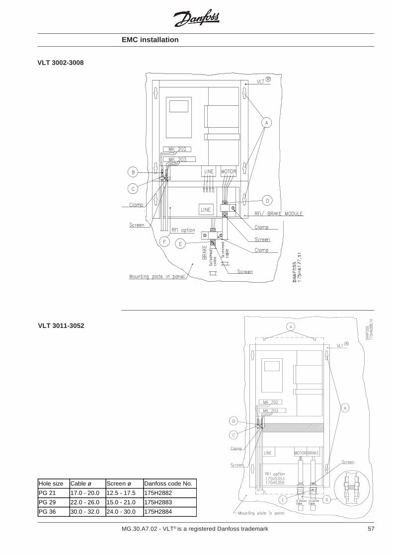
57MG.30.A7.02 - VLT® is a registered Danfoss trademark
EMC installation
VLT 3002-3008
VLT 3011-3052
Hole size Cable ø Screen ø Danfoss code No.
PG 21 17.0 - 20.0 12.5 - 17.5 175H2882
PG 29 22.0 - 26.0 15.0 - 21.0 175H2883
PG 36 30.0 - 32.0 24.0 - 30.0 175H2884
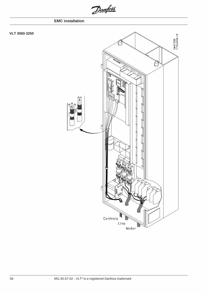
58 MG.30.A7.02 - VLT® is a registered Danfoss trademark
EMC installation
VLT 3060-3250
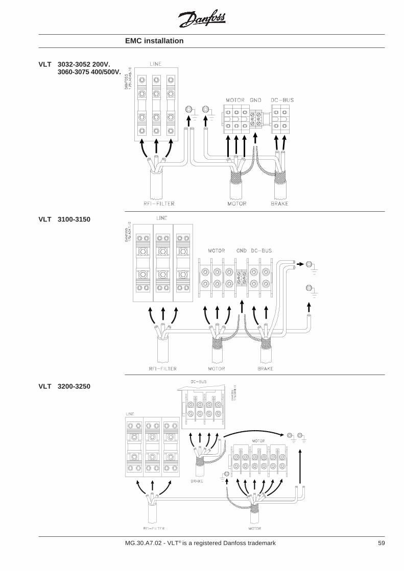
59MG.30.A7.02 - VLT® is a registered Danfoss trademark
VLT 3032-3052 200V.3060-3075 400/500V.
EMC installation
VLT 3100-3150
VLT 3200-3250
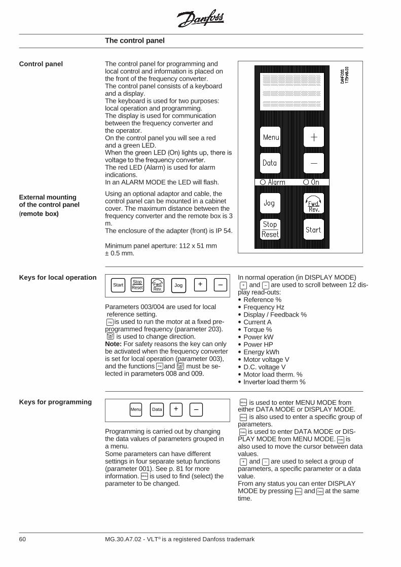
60 MG.30.A7.02 - VLT® is a registered Danfoss trademark
The control panel for programming andlocal control and information is placed onthe front of the frequency converter.The control panel consists of a keyboardand a display.The keyboard is used for two purposes:local operation and programming.The display is used for communicationbetween the frequency converter andthe operator.On the control panel you will see a redand a green LED.When the green LED (On) lights up, there isvoltage to the frequency converter.The red LED (Alarm) is used for alarmindications.In an ALARM MODE the LED will flash.
Using an optional adaptor and cable, thecontrol panel can be mounted in a cabinetcover. The maximum distance between thefrequency converter and the remote box is 3m.The enclosure of the adapter (front) is IP 54.
Minimum panel aperture: 112 x 51 mm± 0.5 mm.
The control panel
Keys for programming
Programming is carried out by changingthe data values of parameters grouped ina menu.Some parameters can have differentsettings in four separate setup functions(parameter 001). See p. 81 for moreinformation. is used to find (select) theparameter to be changed.
Menu is used to enter MENU MODE fromeither DATA MODE or DISPLAY MODE.
Menu is also used to enter a specific group ofparameters.
Data is used to enter DATA MODE or DIS-PLAY MODE from MENU MODE. Data isalso used to move the cursor between datavalues.
+ and – are used to select a group ofparameters, a specific parameter or a datavalue.From any status you can enter DISPLAYMODE by pressing Menu and Data at the sametime.
Menu Data + –
External mountingof the control panel(remote box)
In normal operation (in DISPLAY MODE)+ and – are used to scroll between 12 dis-
play read-outs:• Reference %• Frequency Hz• Display / Feedback %• Current A• Torque %• Power kW• Power HP• Energy kWh• Motor voltage V• D.C. voltage V• Motor load therm. %• Inverter load therm %
Parameters 003/004 are used for local reference setting.
Jog is used to run the motor at a fixed pre-programmed frequency (parameter 203).
Fwd.Rev.
is used to change direction.Note: For safety reasons the key can onlybe activated when the frequency converteris set for local operation (parameter 003),and the functions Jog and Fwd.
Rev.
must be se-lected in parameters 008 and 009.
Keys for local operationStart
StopReset
Fwd.Rev.
Jog + –
Control panel
Menu
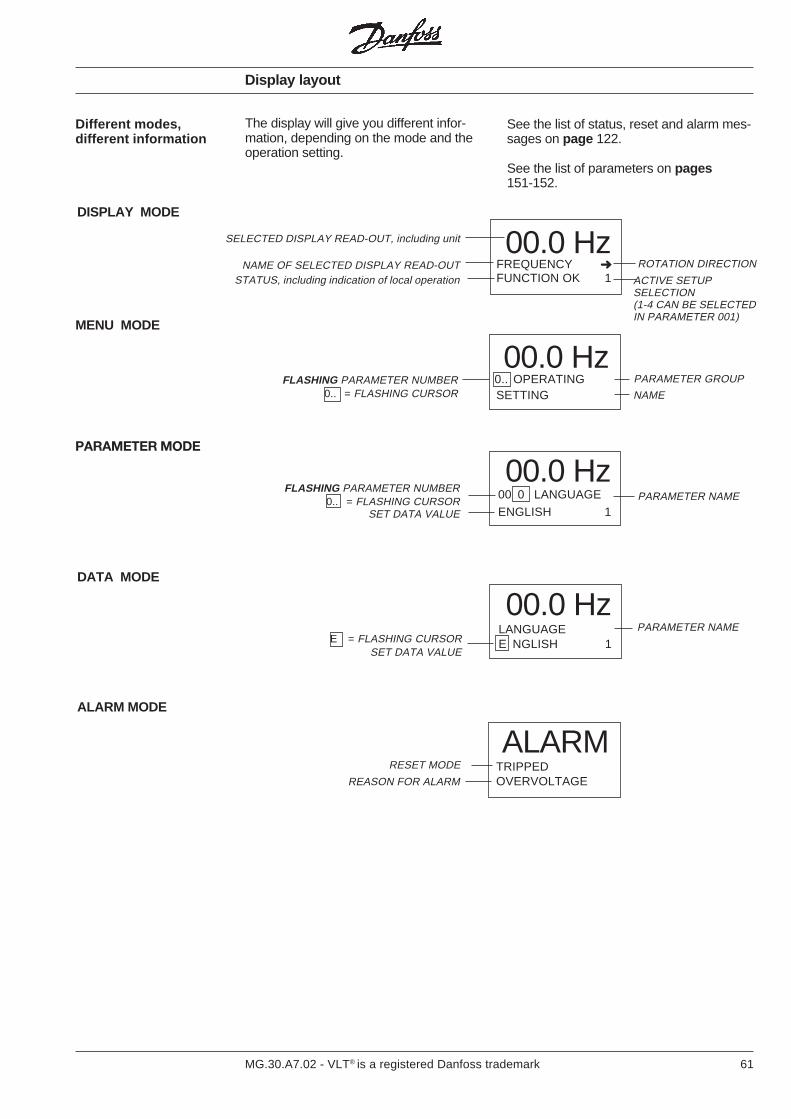
61MG.30.A7.02 - VLT® is a registered Danfoss trademark
Different modes,different information
See the list of status, reset and alarm mes-sages on page 122.
See the list of parameters on pages151-152.
00.0 HzFREQUENCY FUNCTION OK 1
RESET MODE
REASON FOR ALARM
SET DATA VALUE
FLASHING PARAMETER NUMBER0.. = FLASHING CURSOR
STATUS, including indication of local operationNAME OF SELECTED DISPLAY READ-OUT
SELECTED DISPLAY READ-OUT, including unit
ACTIVE SETUPSELECTION(1-4 CAN BE SELECTEDIN PARAMETER 001)
PARAMETER NAME
NAMEFLASHING PARAMETER NUMBER
0.. = FLASHING CURSOR
E = FLASHING CURSORSET DATA VALUE
ROTATION DIRECTION
PARAMETER GROUP
PARAMETER NAME
00.0 Hz0.. OPERATINGSETTING
00.0 Hz00 0 LANGUAGE
ENGLISH 1
00.0 HzLANGUAGEE NGLISH 1
The display will give you different infor-mation, depending on the mode and theoperation setting.
DISPLAY MODE
MENU MODE
PARAMETER MODE
DATA MODE
ALARM MODE
ALARMTRIPPEDOVERVOLTAGE
Display layout
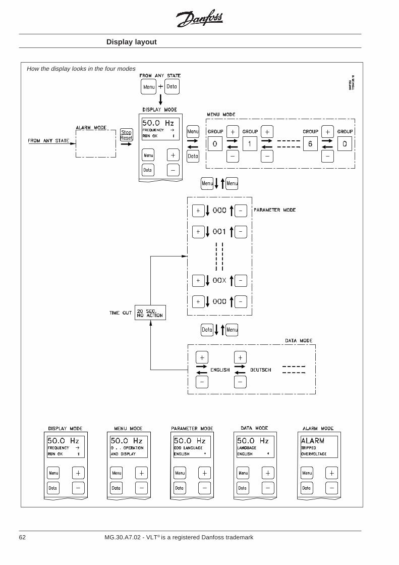
62 MG.30.A7.02 - VLT® is a registered Danfoss trademark
How the display looks in the four modes
Display layout
63MG.30.A7.02 - VLT® is a registered Danfoss trademark
Initialization is used to return to a knowninitial status (factory setting).This requirement arises on change ofsoftware version, if so many of the para-meters have been changed that thesituation is no longer clear, or if the VLT® is
Initialization
General behaving strangely and cannot be reset inthe normal way.
Fundamentally, initialization takes place intwo ways:
(Press the keys MENU + DATA + JOGsimultaneously with mains connection until“init eeprom” is shown in the third line).
This method is used on:
• Replacement of software version.
This results in:• First time setup of communication
parameters to ensure factory setting.(These parameters are setfrom the unit’s operating panel):
Standard(RS 485) 500 Address
501 Baud Rate
Profibus 820 Baud Rate821 FMS/DP select822 Station Delay904 PPO Write918 Station Address
• Reset of operation data (para. 600) andfault memory (para. 602)
• Initialization of all other parameters as de- scribed under initialization via parameter 604
Manual initialization
Initialization viaparameter 604
This method is used on:
• Initialization of all parameters to factorysetting, except for:Communicationparameters (para. 500 and 501) andthe aforementioned Profibus para-meters if this option is installed.Operation data (para. 600)Fault memory (para. 602)
NB! If only factory setting of data in asingle setup is required, ”Factory set” canbe selected in para. 001.
In para. 002 this setting is copied to thechosen setup.

64 MG.30.A7.02 - VLT® is a registered Danfoss trademark
“LOCK” switch There is a way to avoid unwanted pro-gramming. It is done by opening theswitch pin 01 on the control card.
Time out Local reference (parameter 004) is not leftautomatically after 20 seconds.
The display is a three-line LCD display.
Line A is used to display operator read-outs. It will show the value correspondingto the setting in DISPLAY MODE.The selected value will remain in thedisplay line during programming of para-meters.
Line B displays information on parameters,direction, and re-set status.Line C displays information on status andsetup or data value.
The software automatically leaves DATAMODE after 20 seconds if no operation isrecorded.By pressing Data once, it is possible toreturn to DATA MODE and program theparameter which was left after 20 sec.
Display layout
Avoid unwanted data change

65MG.30.A7.02 - VLT® is a registered Danfoss trademark
Please note: You have to press StopReset to stop
the motor before changing the data valuesof some parameters (see factory settings).
Menu build-up The frequency converter has a menu sys-tem with several parameters to be used tooptimise your motor operation.The parameters are divided into 7 groups(group 0 - group 6).
There are also groups for different options.They are described in guidelines for eachoption.
Parameter grouping0.. Operation and display 000-0991.. Load and motor 100-1992.. References and limits 200-2993.. Functions and timers 300-3994.. Inputs and outputs 400-4995.. Serial data interface 500-5996.. Service and diagnosis 600-699
The parameter number is made up of threedigits.The digit on the left indicates the group.
Parameternumbering
Travelling throughthe menu
After the first power-up you will find thefrequency converter in DISPLAY MODE.
Changing groupIf you want to travel through the menu, usethe key Menu followed by the keys + or –
(see page 61).
Changing a parameter numberYou can enter the parameters of theselected group with the key Menu followedby + or – .
+ increases and – decreases theparameter number.
Menu build-up
When you have chosen a parameter andwant to change its data value, press the
Data key followed by the + or – key.
The data value can be a digit or a text.Data value of aparameter
Changing a data value:digit
When you have pressed Data the digit to theright will be active and be shown flashing.The other digits can be activated one byone by pressing Data one, two or three times.The activated digit can be changed bypressing + or – .
Changing a data value:text
If the data value of the chosen parameteris a text, the display shows the selectedtext.This can be changed by pressing Data
and then + or – . All options are thenshown one by one. The text shown in thedisplay will be stored at the same momentyou leave DATA MODE.
You are storing the data value by pressingMenu . Now you have activated the para-
meter number and can travel through thegroup of parameters again using + and – .
Leaving DATA mode
Within each group the parameters arenumbered, starting with 0.For example, in group 1..: 100, 101, 102....
A new data value is stored on leavingDATA MODE, or automatically after 20seconds.Please note: You have to press Stop
Reset to stopthe motor before changing the data valuesof some parameters (see factory settings).

66 MG.30.A7.02 - VLT® is a registered Danfoss trademark
Group description
Note: The choice between the 12 differentdisplay read-outs mentioned on page 60 isnot an element of this group.
Load and motorGroup 1..
Operation and displayGroup 0..
In this group you will find parametersconcerning the display read-out, localoperation and setup handling.
This group of parameters has been re-ser-ved for the adjustments necessary toadapt the VLT® frequency converter to theapplication and motor.
The preprogrammed values in parameters100-105 are suitable for normal applicationusing standard asynchronous motors withconstant torque load without parallel-coupled motors.
If quadratic torque load is applied, selectone of the VT (variable torque) modes or VTmodes with CT starting torque (high break-away torque).
Parallel-coupled motors:If parallel-coupled motors or any synchro-nous type of motor are used at the outputfrom a VLT® frequency converter, constanttorque is selected without start compensa-tion in parameter 100, and open-loop speedcontrol is selected in parameter 101.
Auto-optimization:An additional tuning might improve thetorque yield or speed accuracy, if the motordata differ from the typical values assumedas default.
Items 1-4 in Quick setup must be carried outfirst.The adaptive tuning facility offers you aneasy way to perform that tuning. Initiatethe tuning by setting parameter 106 to"ON" and pressing Start .
The VLT® will perform a test measurementof vital motor data and automatically adjustthe appropriate parameters (108-113).
For optimum adjustment automatic para-meter tuning on a cold motor is recom-mended.
Caution: the motor will start running withoutwarning.Manual tuning is possible in parameters109-113 for correction of default or auto-matically tuned values.
Closed loopIf closed loop control is required the trans-mitter, tachometer or encoder should sup-ply one of the standard analogue signals(e.g. 0-10 V, 0-20 mA; 4-20 mA) or a pulsesignal frequency of max. 100 Hz, 1 kHz or10 kHz (programmable).The full-scale value is always 100%.
The transmitter signal should be selectedto utilise the full scale range as far aspossible, but with due allowance for over-shooting.The pulse signal has an over-shootingrange of up to 200% for the 100 Hz and1 kHz signals, and up to 130% for the10 kHz signal.To optimise dynamics and accuracy an im-pulse frequency as close to 10 kHz as pos-sible should be selected (at max.motor speed).If this is not possible, the transmitter signalcan be corrected by the feedback scalingfactor (parameter 125).
The equivalent reference signal can eitherbe fixed internally (digital reference) or sup-plied via standard analogue signals or thepulse signal (range 0-100%). It is not possi-ble to select the same type of signal (volt-age, current, pulses) for both the referenceand the feedback.
At start the output frequency is determinedby the frequency converter’s reference andthe feed forward factor and the min/maxfrequency settings. The feed forward factoris used to set the steady state output fre-quency.
Feedback scaling is used if the transmittercannot be optimally selected for the inputsignals’ scale range.
The PID regulator then adjusts the outputfrequency by comparing reference andfeedback.
At stop the controller output (integrator) isset to 0 so that a restart follows the normalstart situation.
Continued...

67MG.30.A7.02 - VLT® is a registered Danfoss trademark
Group description
Load and motorsGroup 1..(continued)
PID optimisation
Parameter 121(proportional gain) is set for 0.01(min. value, factory setting).
Parameter 122(integration time) is set for infinite(max. value, factory setting).
Parameter 123(differentiation time) is set for 0 sec.
1. Start the frequency converter.2. Increase the value in parameter 121
(proportional amplification) until thefeedback signal (FB) oscillatesconstantly. Reduce the value until theoscillation ceases. Reduce further(0.4-0.6 times).
3. Reduce the value in parameter 122(integration time) until the feedbacksignal (FB) oscillates again. Increasethe value until the oscillation ceases.Then increase further 1.15-1.5 times.
4. Parameter 123 (differentiation time) isonly used in fast systems. The typicalvalue is the integration time dividedby 4.
5. Reduce control range if necessary(parameter 120) to reduce over-shooting.
Note:The drive should be started / stoppedrepeatedly to ensure stability.
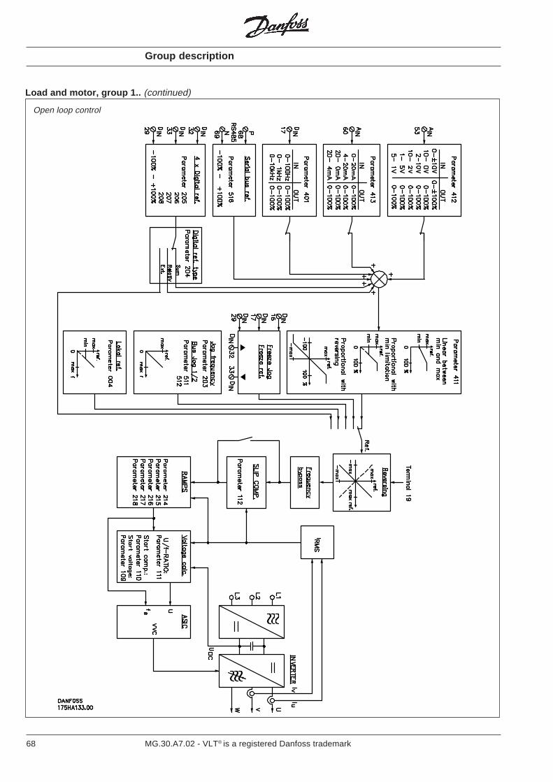
68 MG.30.A7.02 - VLT® is a registered Danfoss trademark
Load and motor, group 1.. (continued)
Open loop control
Group description
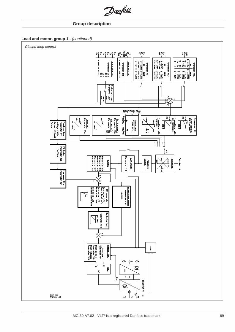
69MG.30.A7.02 - VLT® is a registered Danfoss trademark
Load and motor, group 1.. (continued)
Closed loop control
Group description
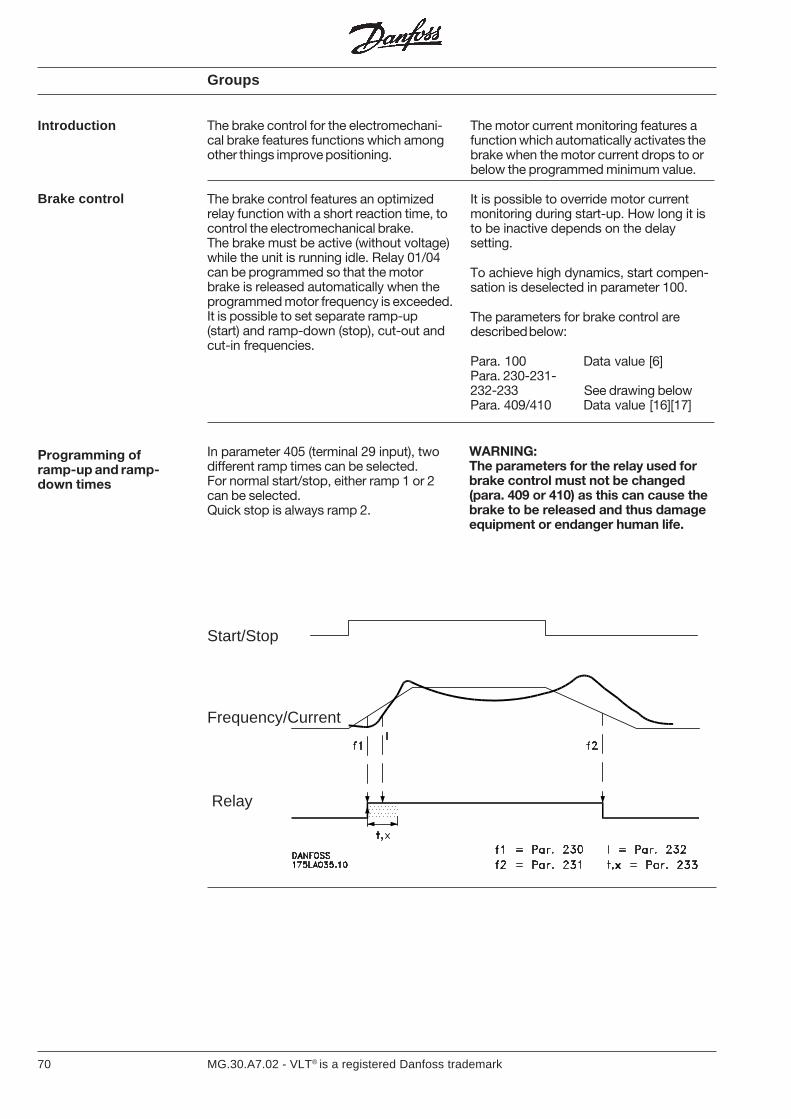
70 MG.30.A7.02 - VLT® is a registered Danfoss trademark
The brake control for the electromechani-cal brake features functions which amongother things improve positioning.
The brake control features an optimizedrelay function with a short reaction time, tocontrol the electromechanical brake.The brake must be active (without voltage)while the unit is running idle. Relay 01/04can be programmed so that the motorbrake is released automatically when theprogrammed motor frequency is exceeded.It is possible to set separate ramp-up(start) and ramp-down (stop), cut-out andcut-in frequencies.
Groups
Introduction
Brake control
The motor current monitoring features afunction which automatically activates thebrake when the motor current drops to orbelow the programmed minimum value.
It is possible to override motor currentmonitoring during start-up. How long it isto be inactive depends on the delaysetting.
To achieve high dynamics, start compen-sation is deselected in parameter 100.
The parameters for brake control aredescribed below:
Para. 100 Data value [6]Para. 230-231-232-233 See drawing belowPara. 409/410 Data value [16][17]
Start/Stop
Frequency/Current
Relay
Programming oframp-up and ramp-down times
In parameter 405 (terminal 29 input), twodifferent ramp times can be selected.For normal start/stop, either ramp 1 or 2can be selected.Quick stop is always ramp 2.
WARNING:The parameters for the relay used forbrake control must not be changed(para. 409 or 410) as this can cause thebrake to be released and thus damageequipment or endanger human life.
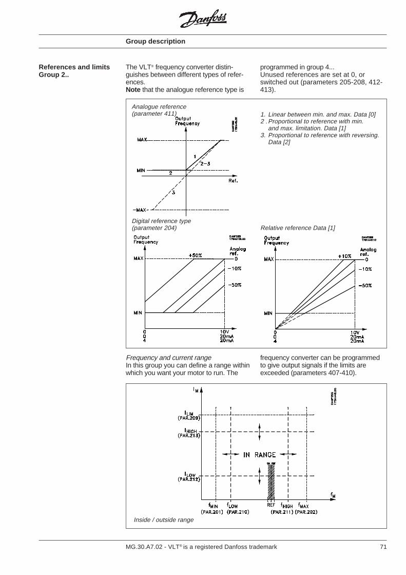
71MG.30.A7.02 - VLT® is a registered Danfoss trademark
The VLT® frequency converter distin-guishes between different types of refer-ences.Note that the analogue reference type is
Inside / outside range
References and limitsGroup 2..
Analogue reference(parameter 411)
Digital reference type(parameter 204) Relative reference Data [1]
1. Linear between min. and max. Data [0]2 .Proportional to reference with min.
and max. limitation. Data [1]3. Proportional to reference with reversing.
Data [2]
programmed in group 4...Unused references are set at 0, orswitched out (parameters 205-208, 412-413).
frequency converter can be programmedto give output signals if the limits areexceeded (parameters 407-410).
Frequency and current rangeIn this group you can define a range withinwhich you want your motor to run. The
Group description
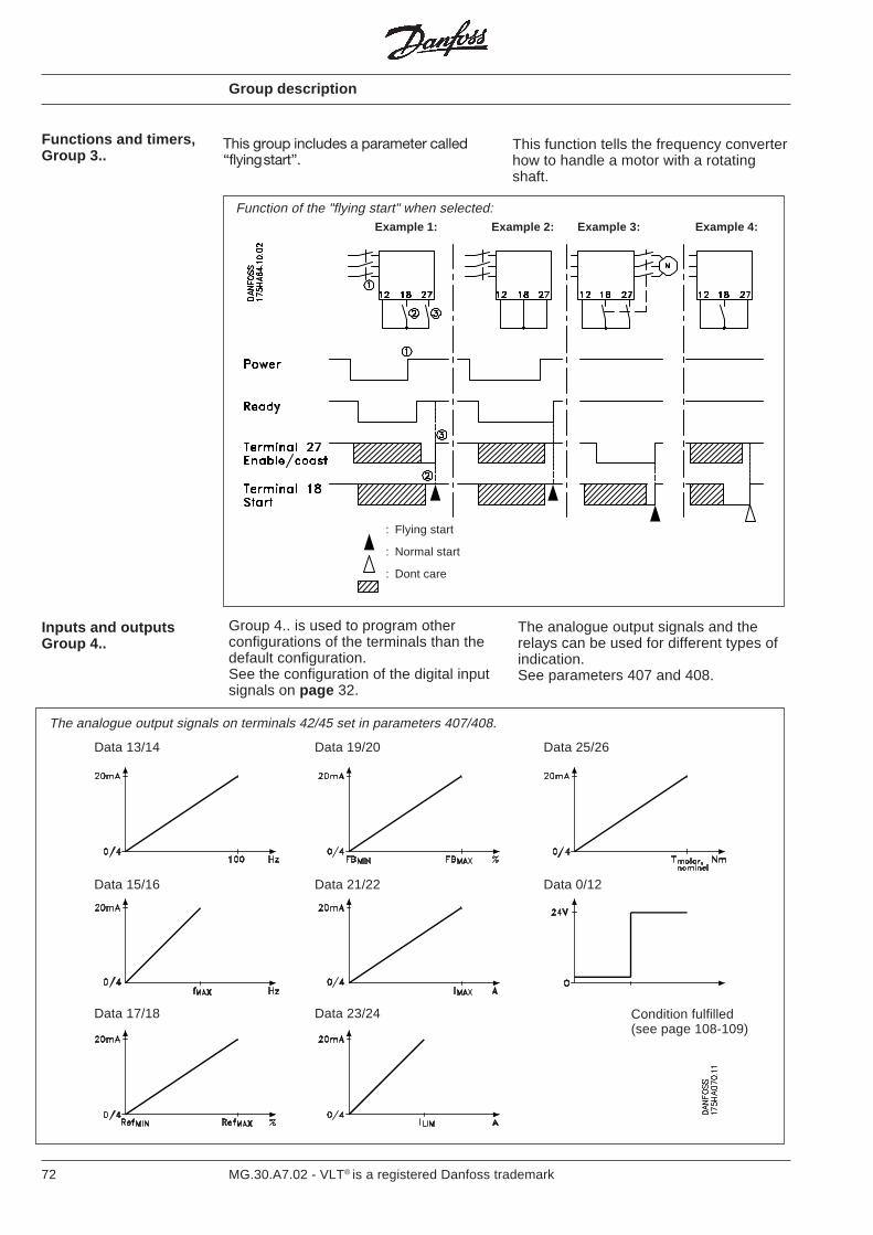
72 MG.30.A7.02 - VLT® is a registered Danfoss trademark
This group includes a parameter called“flying start”.
This function tells the frequency converterhow to handle a motor with a rotatingshaft.
: Flying start
: Normal start
: Dont care
Example 1: Example 2: Example 3: Example 4:
Condition fulfilled(see page 108-109)
Function of the "flying start" when selected:
Data 13/14 Data 19/20 Data 25/26
Data 15/16 Data 21/22 Data 0/12
Data 17/18 Data 23/24
The analogue output signals on terminals 42/45 set in parameters 407/408.
Group description
The analogue output signals and therelays can be used for different types ofindication.See parameters 407 and 408.
Group 4.. is used to program otherconfigurations of the terminals than thedefault configuration.See the configuration of the digital inputsignals on page 32.
Inputs and outputsGroup 4..
Functions and timers,Group 3..
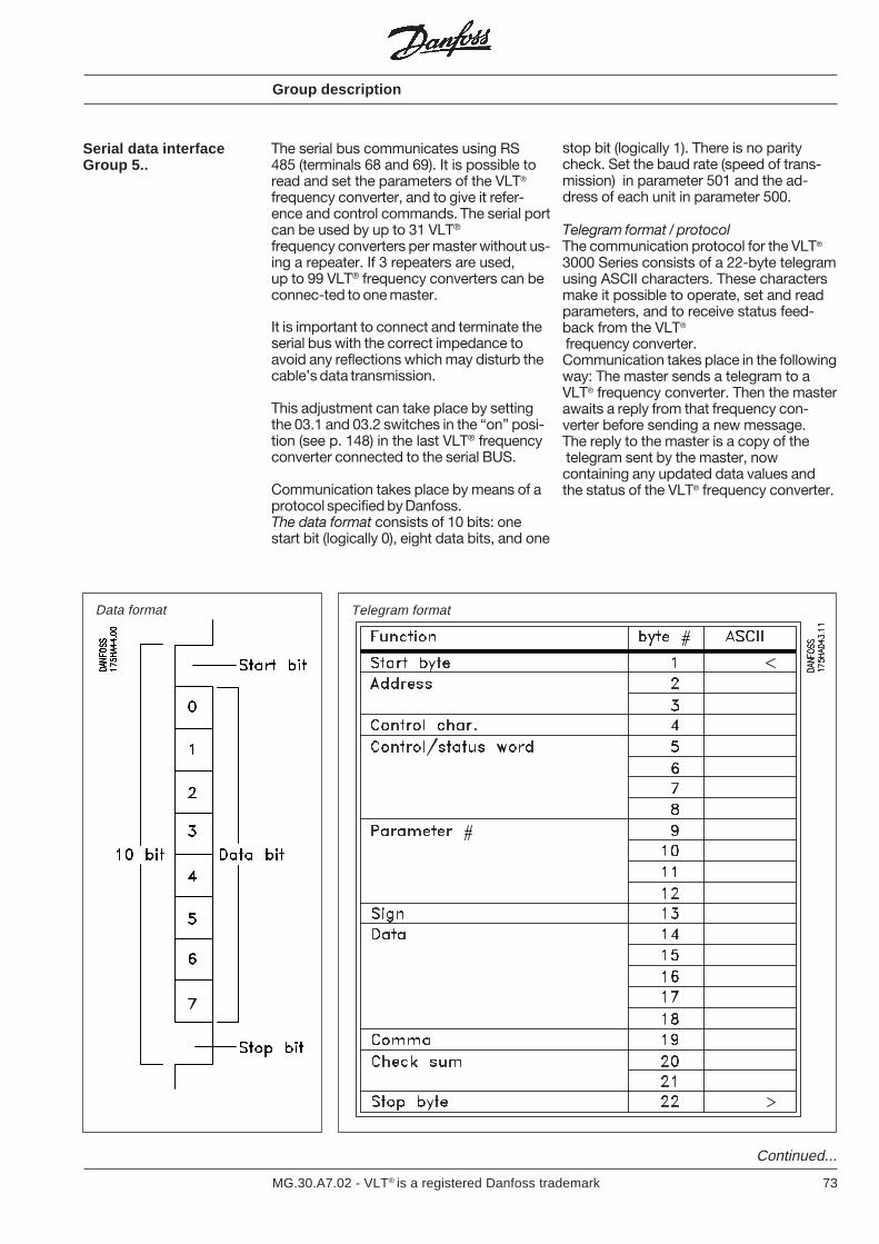
73MG.30.A7.02 - VLT® is a registered Danfoss trademark
Serial data interfaceGroup 5..
The serial bus communicates using RS485 (terminals 68 and 69). It is possible toread and set the parameters of the VLT®
frequency converter, and to give it refer-ence and control commands. The serial portcan be used by up to 31 VLT®
frequency converters per master without us-ing a repeater. If 3 repeaters are used,up to 99 VLT® frequency converters can beconnec-ted to one master.
It is important to connect and terminate theserial bus with the correct impedance toavoid any reflections which may disturb thecable’s data transmission.
This adjustment can take place by settingthe 03.1 and 03.2 switches in the “on” posi-tion (see p. 148) in the last VLT® frequencyconverter connected to the serial BUS.
Communication takes place by means of aprotocol specified by Danfoss.The data format consists of 10 bits: onestart bit (logically 0), eight data bits, and one
stop bit (logically 1). There is no paritycheck. Set the baud rate (speed of trans-mission) in parameter 501 and the ad-dress of each unit in parameter 500.
Telegram format / protocolThe communication protocol for the VLT®
3000 Series consists of a 22-byte telegramusing ASCII characters. These charactersmake it possible to operate, set and readparameters, and to receive status feed-back from the VLT®
frequency converter.Communication takes place in the followingway: The master sends a telegram to aVLT® frequency converter. Then the masterawaits a reply from that frequency con-verter before sending a new message.The reply to the master is a copy of the telegram sent by the master, nowcontaining any updated data values andthe status of the VLT® frequency converter.
Data format Telegram format
Continued...
Group description
74 MG.30.A7.02 - VLT® is a registered Danfoss trademark
Serial data interfaceGroup 5..(continued)
Byte 1:Start byte which in this case must be thecharacter ”<” (ASCII: 60).
Bytes 2 and 3:The two-digit address of the frequencyconverter with which communication isrequired. This address is also programmedin parameter 500.Sending to address 00 means broadcastto all units connected to the bus. None ofthe units will reply, but they will carry out thecommand.
Byte 4:Control parameter telling the VLT®
frequency converter what to do with thefollowing data values.
U (update) means that the data value(bytes 13-19) must be read into thefrequency converter’s parameter (bytes9-13).
R (read) means that the master wants toread the data value of the parameterstated in bytes 9-12.
C (control) means that the frequency con-verter reads only the four command bytes(5-8) and returns with status. Parameternumber and data value will be ignored.
I (read index) means that the frequencyconverter reads index and parameter, andreturns with status.Parameter is stated in bytes 9-12 andindex is stated in bytes 13-18.Parameters with indices are read-onlyparameters. Action will be taken on the con-trol word.Two-dimensional indices (x,y) (parameters601 and 602) are separated by a comma,see byte 19.
Example:Index = x, yData value = 013,05
Byte 14-18 = 013 05
Byte 19 = 2
Group description
Bytes 5-8:Control and status words are used to sendcommands to the frequency converter andto send status from frequency converter tomaster.
Bytes 9-12:In these bytes the parameter number is set.
Bytes 13:Used for the sign before data value inbytes 14-18. All characters other than "−"are taken as "+".
Bytes 14-18:Here is placed the data value of the para-meter stated in bytes 9-12.The value must be a whole number. If adecimal point is needed it is stated in byte19.Note : Some data values have square brack-ets with a number, e.g. [0]. Use this numberinstead of the "text" data value.
Bytes 19:The position of the decimal point in the datavalue stated in bytes 14-18. The numberstates the number of characters after thedecimal point.Byte 19 can then be 0, 1, 2, 3, 4 or 5.For example, the number 23.75 is stated:Byte no. 13 14 15 16 17 18 19ASCII character + 2 3 7 5 0 3If byte 19 = 9 in the response telegram seetable page 80.
Bytes 20, 21:Used for counter control from byte 2 up toand including 19. The decimal values of theASCII characters are added and reduced tothe two “low” characters, e.g. Σ 235 [ ]reduced = 35. If no control is necessary can-cel the function with “?” (ASCII: 63) in thetwo bytes.
Byte 22:Stop byte stating the end of the telegram.The character ”>” is used (ASCII: 62).
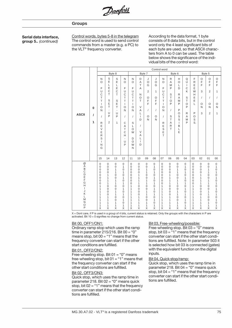
75MG.30.A7.02 - VLT® is a registered Danfoss trademark
According to the data format, 1 byteconsists of 8 data bits, but in the controlword only the 4 least significant bits ofeach byte are used, so that ASCII charac-ters from A to 0 can be used. The tablebelow shows the significance of the indi-vidual bits of the control word:
Control words, bytes 5-8 in the telegramThe control word is used to send controlcommands from a master (e.g. a PC) tothe VLT® frequency converter.
Serial data interface,group 5.. (continued)
Groups
Bit 00, OFF1/ON1:Ordinary ramp stop which uses the ramptime in parameter 215/216. Bit 00 = “0”means stop, bit 00 = “1” means that thefrequency converter can start if the otherstart conditions are fulfilled.Bit 01, OFF2/ON2:Free-wheeling stop. Bit 01 = “0” meansfree-wheeling stop, bit 01 = “1” means thatthe frequency converter can start if theother start conditions are fulfilled.Bit 02, OFF3/ON3:Quick stop, which uses the ramp time inparameter 218. Bit 02 = “0” means quickstop, bit 02 = “1” means that the frequencyconverter can start if the other start condi-tions are fulfilled.
Bit 03, Free-wheeling/possible:Free-wheeling stop. Bit 03 = “0” meansstop, bit 03 = “1” means that the frequencyconverter can start if the other start condi-tions are fulfilled. Note: In parameter 503 itis selected how bit 03 is connected (gates)with the equivalent function on the digitalinputs.Bit 04, Quick stop/ramp:Quick stop, which uses the ramp time inparameter 218. Bit 04 = “0” means quickstop, bit 04 = “1” means that the frequencyconverter can start if the other start condi-tions are fulfilled.
@ABCDEFGHIJKLMNOP
ASCII
0
/
1
X = Dont care, if P is used in a group of 4 bits, current status is retained. Only the groups with the characters in P areactivated. Bit 10 = 0 signifies no change from current status.
15 14 13 12 11 10 09 08 07 06 05 04 03 02 01 00
0 0 0 0 0 0 0 0 0 0 0 0 0 0 0 00 0 0 1 0 0 0 1 0 0 0 1 0 0 0 10 0 1 0 0 0 1 0 0 0 1 0 0 0 1 00 0 1 1 0 0 1 1 0 0 1 1 0 0 1 10 1 0 0 0 1 0 0 0 1 0 0 0 1 0 00 1 0 1 0 1 0 1 0 1 0 1 0 1 0 10 1 1 0 0 1 1 0 0 1 1 0 0 1 1 00 1 1 1 0 1 1 1 0 1 1 1 0 1 1 11 0 0 0 1 0 0 0 1 0 0 0 1 0 0 01 0 0 1 1 0 0 1 1 0 0 1 1 0 0 11 0 1 0 1 0 1 0 1 0 1 0 1 0 1 01 0 1 1 1 0 1 1 1 0 1 1 1 0 1 11 1 0 0 1 1 0 0 1 1 0 0 1 1 0 01 1 0 1 1 1 0 1 1 1 0 1 1 1 0 11 1 1 0 1 1 1 0 1 1 1 0 1 1 1 01 1 1 1 1 1 1 1 1 1 1 1 1 1 1 1X X X X X X X X X X X X X X X X
Byte 8 Byte 7 Byte 6 Byte 5
NO
FUCTTION
/
REVERSING
SELECT
SET-UP
1
NO
FUCTTION
/
CATCH-UP
NO
FUCTTION
/
SLOW
DOWN
DATA
NOT
VALID
/
VALID
JOG
2
OFF
/
ON
JOG
1
OFF
/
ON
NO
FUCTTION
/
RESET
RAMP
STOP
/
START
HOLD
RAMP
POSSIBLE
QUICK
STOP
RAMP
FREEWHEEL
POS
S.
OFF
3
/
ON
3
OFF
2
/
ON
2
OFF
1
/
ON
1
Control word
SELECT
SET-UP
2
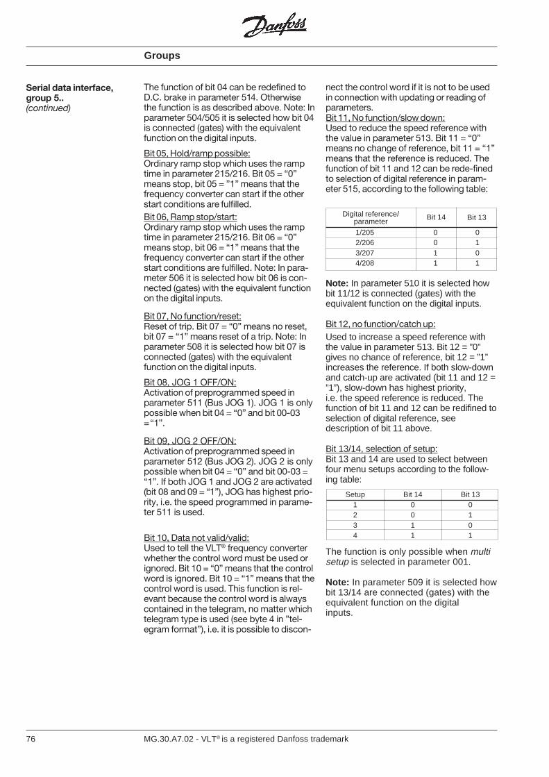
76 MG.30.A7.02 - VLT® is a registered Danfoss trademark
Groups
The function of bit 04 can be redefined toD.C. brake in parameter 514. Otherwisethe function is as described above. Note: Inparameter 504/505 it is selected how bit 04is connected (gates) with the equivalentfunction on the digital inputs.
Bit 05, Hold/ramp possible:Ordinary ramp stop which uses the ramptime in parameter 215/216. Bit 05 = “0”means stop, bit 05 = ”1” means that thefrequency converter can start if the otherstart conditions are fulfilled.Bit 06, Ramp stop/start:Ordinary ramp stop which uses the ramptime in parameter 215/216. Bit 06 = “0”means stop, bit 06 = “1” means that thefrequency converter can start if the otherstart conditions are fulfilled. Note: In para-meter 506 it is selected how bit 06 is con-nected (gates) with the equivalent functionon the digital inputs.
Bit 07, No function/reset:Reset of trip. Bit 07 = “0” means no reset,bit 07 = “1” means reset of a trip. Note: Inparameter 508 it is selected how bit 07 isconnected (gates) with the equivalentfunction on the digital inputs.
Bit 08, JOG 1 OFF/ON:Activation of preprogrammed speed inparameter 511 (Bus JOG 1). JOG 1 is onlypossible when bit 04 = “0” and bit 00-03= “1”.
Bit 09, JOG 2 OFF/ON:Activation of preprogrammed speed inparameter 512 (Bus JOG 2). JOG 2 is onlypossible when bit 04 = “0” and bit 00-03 =“1”. If both JOG 1 and JOG 2 are activated(bit 08 and 09 = “1”), JOG has highest prio-rity, i.e. the speed programmed in parame-ter 511 is used.
Bit 10, Data not valid/valid:Used to tell the VLT® frequency converterwhether the control word must be used orignored. Bit 10 = “0” means that the controlword is ignored. Bit 10 = “1” means that thecontrol word is used. This function is rel-evant because the control word is alwayscontained in the telegram, no matter whichtelegram type is used (see byte 4 in ”tel-egram format”), i.e. it is possible to discon-
nect the control word if it is not to be usedin connection with updating or reading ofparameters.Bit 11, No function/slow down:Used to reduce the speed reference withthe value in parameter 513. Bit 11 = “0”means no change of reference, bit 11 = “1”means that the reference is reduced. Thefunction of bit 11 and 12 can be rede-finedto selection of digital reference in param-eter 515, according to the following table:
Serial data interface,group 5..(continued)
Digital reference/parameter
Bit 14 Bit 13
1/205 0 02/206 0 13/207 1 04/208 1 1
Note: In parameter 510 it is selected howbit 11/12 is connected (gates) with theequivalent function on the digital inputs.
Bit 12, no function/catch up:Used to increase a speed reference withthe value in parameter 513. Bit 12 = ”0”gives no chance of reference, bit 12 = ”1”increases the reference. If both slow-downand catch-up are activated (bit 11 and 12 =”1”), slow-down has highest priority,i.e. the speed reference is reduced. Thefunction of bit 11 and 12 can be redifined toselection of digital reference, seedescription of bit 11 above.
Bit 13/14, selection of setup:Bit 13 and 14 are used to select betweenfour menu setups according to the follow-ing table:
Setup Bit 14 Bit 131 0 02 0 13 1 04 1 1
The function is only possible when multisetup is selected in parameter 001.
Note: In parameter 509 it is selected howbit 13/14 are connected (gates) with theequivalent function on the digitalinputs.
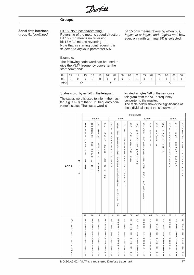
77MG.30.A7.02 - VLT® is a registered Danfoss trademark
Serial data interface,group 5.. (continued)
Groups
Bit 15, No function/reversing:Reversing of the motor’s speed direction.Bit 15 = ”0” means no reversing,bit 15 = ”1” means reversing.Note that as starting point reversing isselected to digital in parameter 507,
Bit 15 14 13 12 11 10 09 08 07 06 05 04 03 02 01 000/1 0 0 0 0 0 1 0 0 0 1 1 1 1 1 1 1ASCII @ D G O
The status word is used to inform the mas-ter (e.g. a PC) of the VLT® frequency con-verter’s status. The status word is
Status word, bytes 5-8 in the telegram
The following code word can be used togive the VLT® frequency converter thestart command:
bit 15 only means reversing when bus,logical or or logical and (logical and, how-ever, only with terminal 19) is selected.
located in bytes 5-8 of the responsetelegram from the VLT® frequencyconverter to the master.The table below shows the significance ofthe individual bits of the status word:
Example:
@ABCDEFGHIJKLMNO
ASCII
0
/
1
TIMERS
OK/OVER
LIMIT
CURRENT
OK/OVER
LIMIT
VOLTAGE
OK/OVER
LIMIT
VLT
OK/STALLS,
AUTO
START
NOT
RUNNING/RUNNING
OUT
OF
OPERATION
RANGE/FREQUENCY
LIMITS
OK
LOCAL
OPERATION/BUS
CONTROL
NOT
ON
REF/ON
REF
NO
WARNING/
WARNING
START
POSSIBLE/START
NOT
POSSIBLE
ON
3/oFF
3
ON
2/OFF
2
NO
FAULT/TRIP
NOT
ENABLED/ENABLED
VLT
NOT
READY/READY
CONTROL
NOT
READY/READY
Status word
Byte 8 Byte 7 Byte 6 Byte 5
15 14 13 12 11 10 09 08 07 06 05 04 03 02 01 00
0 0 0 0 0 0 0 0 0 0 0 0 0 0 0 00 0 0 1 0 0 0 1 0 0 0 1 0 0 0 10 0 1 0 0 0 1 0 0 0 1 0 0 0 1 00 0 1 1 0 0 1 1 0 0 1 1 0 0 1 10 1 0 0 0 1 0 0 0 1 0 0 0 1 0 00 1 0 1 0 1 0 1 0 1 0 1 0 1 0 10 1 1 0 0 1 1 0 0 1 1 0 0 1 1 00 1 1 1 0 1 1 1 0 1 1 1 0 1 1 11 0 0 0 1 0 0 0 1 0 0 0 1 0 0 01 0 0 1 1 0 0 1 1 0 0 1 1 0 0 11 0 1 0 1 0 1 0 1 0 1 0 1 0 1 01 0 1 1 1 0 1 1 1 0 1 1 1 0 1 11 1 0 0 1 1 0 0 1 1 0 0 1 1 0 01 1 0 1 1 1 0 1 1 1 0 1 1 1 0 11 1 1 0 1 1 1 0 1 1 1 0 1 1 1 01 1 1 1 1 1 1 1 1 1 1 1 1 1 1 1
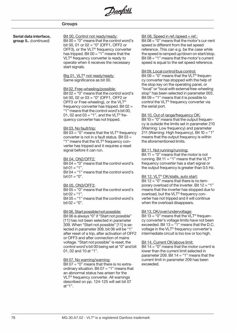
78 MG.30.A7.02 - VLT® is a registered Danfoss trademark
Bit 00, Control not ready/ready:Bit 00 = “0” means that the control word’sbit 00, 01 or 02 = “0” (OFF1, OFF2 orOFF3), or the VLT® frequency converterhas tripped. Bit 00 = “1” means that theVLT® frequency converter is ready tooperate when it receives the necessarystart signals.
Big 01, VLT® not ready/ready:Same significance as bit 00.
Bit 02, Free-wheeling/possible:Bit 02 = “0” means that the control word’sbit 00, 02 or 03 = “0” (OFF1, OFF2 orOFF3 or Free-wheeling), or the VLT®
frequency converter has tripped. Bit 02 =“1” means that the control word’s bit 00,01, 02 and 03 = “1”, and the VLT® fre-quency converter has not tripped.
Bit 03, No fault/trip:Bit 03 = “0” means that the VLT® frequencyconverter is not in a fault status. Bit 03 =“1” means that the VLT® frequency con-verter has tripped and it requires a resetsignal before it can run.
Bit 04, ON2/OFF2:Bit 04 = “0” means that the control word’sbit 01 = “1”.Bit 04 = “1” means that the control word’sbit 01 = “0”.
Bit 05, ON3/OFF3:Bit 05 = “0” means that the control word’sbit 02 = “1”.Bit 05 = “1” means that the control word’sbit 02 = “0”.
Bit 06, Start possible/not possible:Bit 06 is always “0” if “Start not possible”[11] has not been selected in parameter309. When “Start not possible” [11] is se-lected in parameter 309, bit 06 will be “1”after reset of a trip, after activation of OFF2or OFF3 and after connection of mainsvoltage. “Start not possible” is reset, thecontrol word’s bit 00 being set at “0” and bit01, 02 and 10 at “1”.
Bit 07, No warning/warning:Bit 07 = “0” means that there is no extra-ordinary situation. Bit 07 = “1” means thatan abnormal status has arisen for theVLT® frequency converter. All warningsdescribed on pp. 124-125 will set bit 07at “1”.
Bit 08, Speed in ref./speed = ref.:Bit 08 = “0” means that the motor’s cur-rentspeed is different from the set speedreference. This can e.g. be the case whilethe speed is ramped up/down on start/stop.Bit 08 = “1” means that the motor’s currentspeed is equal to the set speed reference.
Bit 09, Local control/bus control:Bit 09 = “0” means that the VLT® frequen-cy converter has stopped with the help ofthe stop key on the operating panel, or“local” or “local with external free-wheelingstop” has been selected in parameter 003.Bit 09 = “1” means that it is possible tocontrol the VLT® frequency converter viathe serial port.
Bit 10, Out of range/frequency OK:Bit 10 = “0” means that the output frequen-cy is outside the limits set in parameter 210(Warning: Low frequency) and parameter211 (Warning: High frequency). Bit 10 = “1”means that the output frequency is withinthe aforementioned limits.
Bit 11, Not running/running:Bit 11 = “0” means that the motor is notrunning. Bit 11 = “1” means that the VLT®
frequency converter has a start signal orthe output frequency is greater than 0.5 Hz.
Bit 12, VLT® OK/stalls, auto start:Bit 12 = “0” means that there is no tem-porary overload of the inverter. Bit 12 = “1”means that the inverter has stopped due tooverload, but the VLT® frequency con-verter has not tripped and it will continuewhen the overload disappears.
Bit 13, OK/over/undervoltage:Bit 13 = “0” means that the VLT® frequen-cy converter’s voltage limits have not beenexceeded. Bit 13 = “1” means that the D.C.voltage in the VLT® frequency converter’sintermediate circuit is too low or too high.
Bit 14, Current OK/above limit:Bit 14 = “0” means that the motor current islower than the current limit selected inparameter 209. Bit 14 = “1” means that thecurrent limit in parameter 209 has beenexceeded.
Serial data interface,group 5.. (continued)
Groups
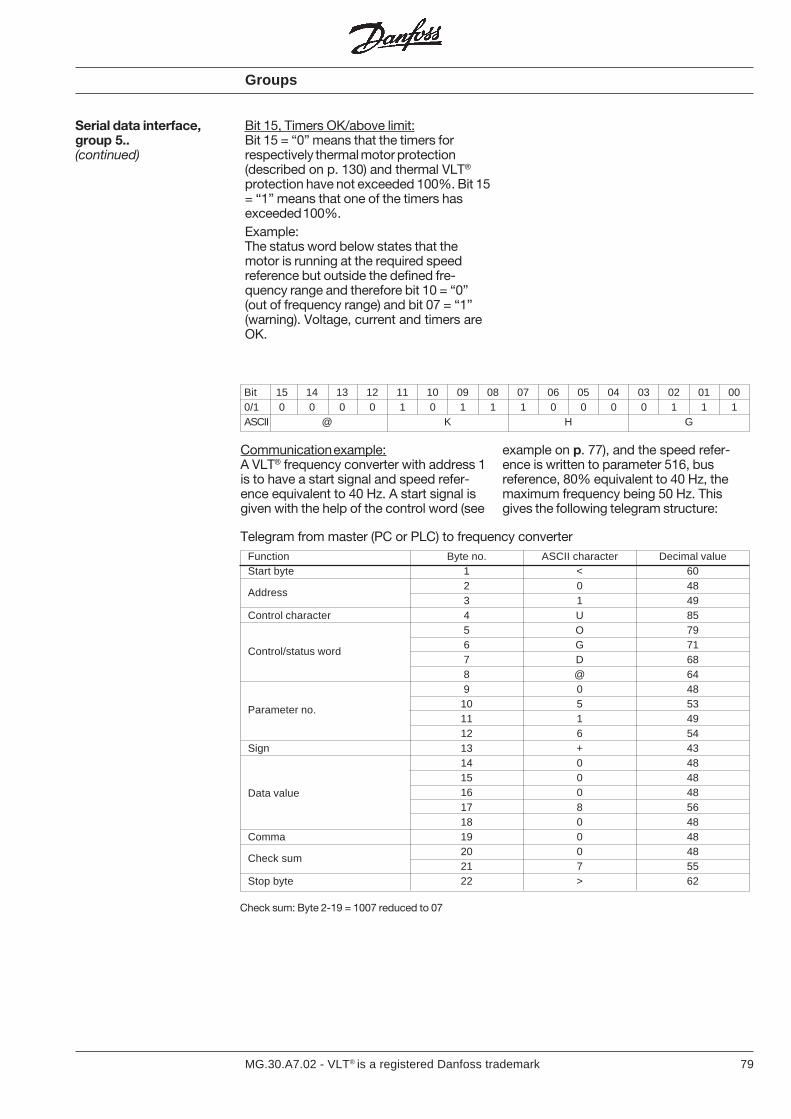
79MG.30.A7.02 - VLT® is a registered Danfoss trademark
Bit 15 14 13 12 11 10 09 08 07 06 05 04 03 02 01 000/1 0 0 0 0 1 0 1 1 1 0 0 0 0 1 1 1ASCII @ K H G
Communication example:A VLT® frequency converter with address 1is to have a start signal and speed refer-ence equivalent to 40 Hz. A start signal isgiven with the help of the control word (see
example on p. 77), and the speed refer-ence is written to parameter 516, busreference, 80% equivalent to 40 Hz, themaximum frequency being 50 Hz. Thisgives the following telegram structure:
Telegram from master (PC or PLC) to frequency converterFunction Byte no. ASCII character Decimal valueStart byte 1 < 60
2 0 483 1 49
Control character 4 U 855 O 796 G 717 D 688 @ 649 0 4810 5 5311 1 4912 6 54
Sign 13 + 4314 0 4815 0 4816 0 4817 8 5618 0 48
Comma 19 0 4820 0 4821 7 55
Stop byte 22 > 62
Data value
Check sum
Check sum: Byte 2-19 = 1007 reduced to 07
Address
Control/status word
Parameter no.
Groups
Bit 15, Timers OK/above limit:Bit 15 = “0” means that the timers forrespectively thermal motor protection(described on p. 130) and thermal VLT®
protection have not exceeded 100%. Bit 15= “1” means that one of the timers hasexceeded 100%.Example:The status word below states that themotor is running at the required speedreference but outside the defined fre-quency range and therefore bit 10 = “0”(out of frequency range) and bit 07 = “1”(warning). Voltage, current and timers areOK.
Serial data interface,group 5..(continued)
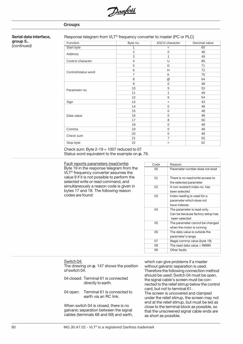
80 MG.30.A7.02 - VLT® is a registered Danfoss trademark
Response telegram from VLT® frequency converter to master (PC or PLC)Function Byte no. ASCII character Decimal valueStart byte 1 < 60
2 0 483 1 49
Control character 4 U 855 G 716 H 727 K 758 @ 649 0 48
10 5 5311 1 4912 6 54
Sign 13 + 4314 0 4815 0 4816 0 4817 8 5618 0 48
Comma 19 0 4820 0 4821 7 55
Stop byte 22 > 62
Check sum: Byte 2-19 = 1007 reduced to 07Status word equivalent to the example on p. 79.
Serial data interface,group 5..(continued)
Fault reports parameters (read/write)Byte 19 in the response telegram from theVLT® frequency converter assumes thevalue 9 if it is not possible to perform theselected write or read command, andsimultaneously a reason code is given inbytes 17 and 18. The following reasoncodes are found:
Address
Control/status word
Parameter no.
Data value
Check sum
Switch 04:The drawing on p. 147 shows the positionof switch 04.
04 closed: Terminal 61 is connecteddirectly to earth.
04 open: Terminal 61 is connected toearth via an RC link.
When switch 04 is closed, there is nogalvanic separation between the signalcables (terminals 68 and 69) and earth,
which can give problems if a masterwithout galvanic separation is used.Therefore the following connection methodshould be used: Switch 04 must be open,the signal cable’s screen must be con-nected to the relief stirrup below the controlcard, but not to terminal 61.The screen is uncovered and clampedunder the relief stirrup, the screen may notend at the relief stirrup, but must be led asclose to the terminal block as possible, sothat the unscreened signal cable ends areas short as possible.
Code Reason00 Parameter number does not exist
01 There is no read/write access tothe selected parameter
02 A non-existent index no. hasbeen selected
03 Index reading is used for aparameter which does nothave indexes
04 The parameter is read-only.Can be because factory setup has
been selected05 The parameter cannot be changed
when the motor is running06 The data value is outside the
parameter’s range07 Illegal comma value (byte 19)08 The read data value > 9999999 Other faults
Groups
81MG.30.A7.02 - VLT® is a registered Danfoss trademark
Service and diagnosis,Group 6..
In group 6, different operating data for usein connection with service and diagnosisare registered. There are also details of theVLT®’s identity and software version.
Groups
82 MG.30.A7.02 - VLT® is a registered Danfoss trademark
= Factory setting. Text in ( ) = Display text.The figures in [ ] are used in bus communication.
000Language select(Language)
Value: English (ENGLISH) [0]German (DEUTSCH) [1]French (FRANCAIS) [2]Danish (DANSK) [3]Spanish (ESPANOL) [4]Italian (ITALIANO) [5]
The choice in this parameter defines thelanguage of the display.
001
Setup selection,operation(Setup operatio)
Value:Factory setup (FACTORY SET) [0]
Setup (SETUP 1) [1]Setup (SETUP 2) [2]Setup (SETUP 3) [3]Setup (SETUP 4) [4]Multi setup (MULTI SETUP) [5]
Example:Setup Terminal 17 Terminal 16
1 0 02 0 13 1 04 1 1
Function:The menu setup to control the VLT®
frequency converter can be selected. Theparameters which can be changed arestated on pp. 149-150. If several setupsare required, up to four different alterna-tives can be selected. Remote-controlledselection between different setups can beoperated from terminals 16/17 or 32/33 andthe serial port.
Description of choices:Factory setup contains the factory-pro-grammed data. Can be used as a datasource if the other setups are to be re-turned to a known status. Here the lan-guage is always English. It is not possibleto change any other data when this setupis selected.Setup 1-4 is four individual setups whichcan be used as required. The currentrunning setup can be changed, and thechanges have an immediate impact on theunit’s function.Multi setup is used for remote-controlledoperation between more than one setup.Terminal 16/17 (para. 400/401), terminal32/33 (para. 406) or the serial bus can beused to alternate between the setups.
Parameter description 0.. Operation and display
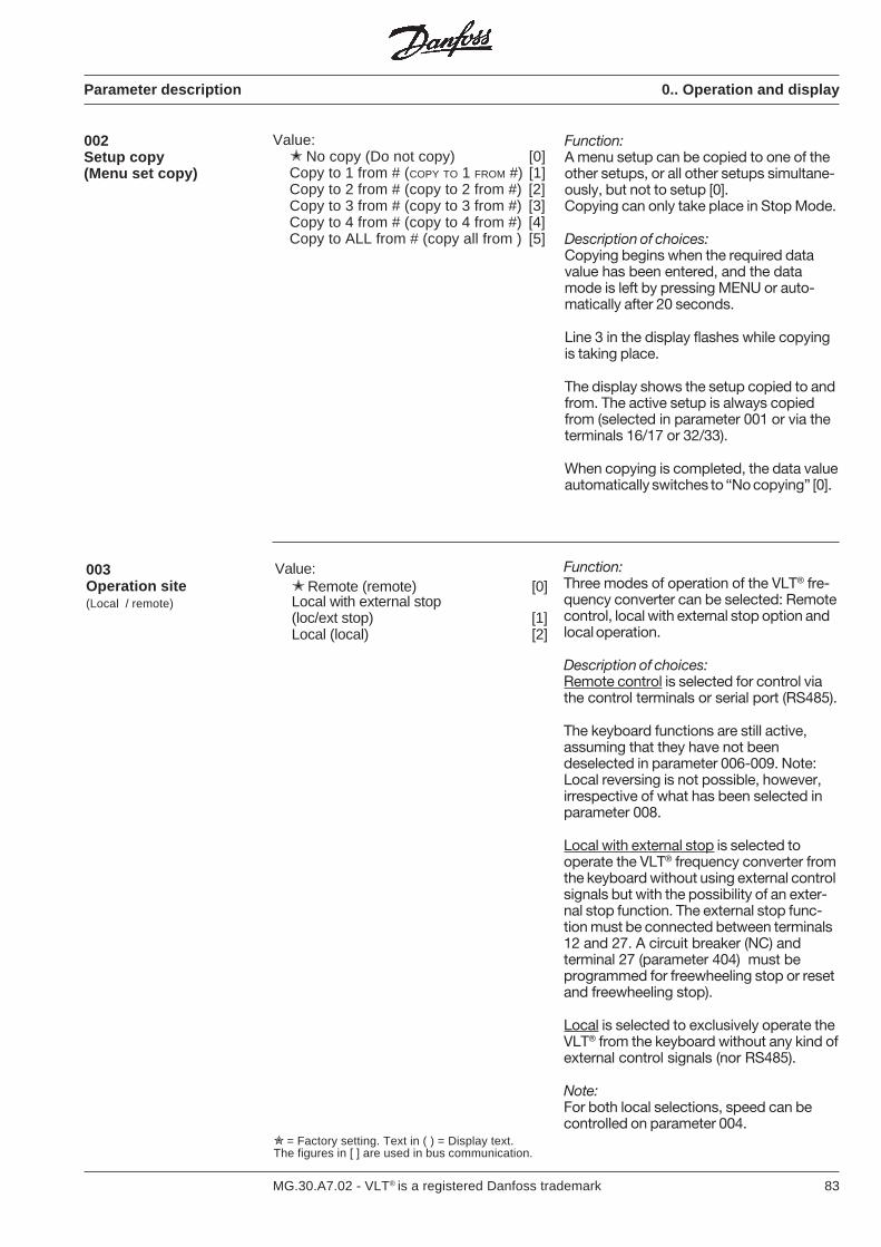
83MG.30.A7.02 - VLT® is a registered Danfoss trademark
Parameter description 0.. Operation and display
= Factory setting. Text in ( ) = Display text.The figures in [ ] are used in bus communication.
002Setup copy(Menu set copy)
Value: No copy (Do not copy) [0]Copy to 1 from # (COPY TO 1 FROM #) [1]Copy to 2 from # (copy to 2 from #) [2]Copy to 3 from # (copy to 3 from #) [3]Copy to 4 from # (copy to 4 from #) [4]Copy to ALL from # (copy all from ) [5]
Function:A menu setup can be copied to one of theother setups, or all other setups simultane-ously, but not to setup [0].Copying can only take place in Stop Mode.
Description of choices:Copying begins when the required datavalue has been entered, and the datamode is left by pressing MENU or auto-matically after 20 seconds.
Line 3 in the display flashes while copyingis taking place.
The display shows the setup copied to andfrom. The active setup is always copiedfrom (selected in parameter 001 or via theterminals 16/17 or 32/33).
When copying is completed, the data valueautomatically switches to “No copying” [0].
003Operation site(Local / remote)
Value: Remote (remote) [0]Local with external stop(loc/ext stop) [1]Local (local) [2]
Function:Three modes of operation of the VLT® fre-quency converter can be selected: Remotecontrol, local with external stop option andlocal operation.
Description of choices:Remote control is selected for control viathe control terminals or serial port (RS485).
The keyboard functions are still active,assuming that they have not beendeselected in parameter 006-009. Note:Local reversing is not possible, however,irrespective of what has been selected inparameter 008.
Local with external stop is selected tooperate the VLT® frequency converter fromthe keyboard without using external controlsignals but with the possibility of an exter-nal stop function. The external stop func-tion must be connected between terminals12 and 27. A circuit breaker (NC) andterminal 27 (parameter 404) must beprogrammed for freewheeling stop or resetand freewheeling stop).
Local is selected to exclusively operate theVLT® from the keyboard without any kind ofexternal control signals (nor RS485).
Note:For both local selections, speed can becontrolled on parameter 004.
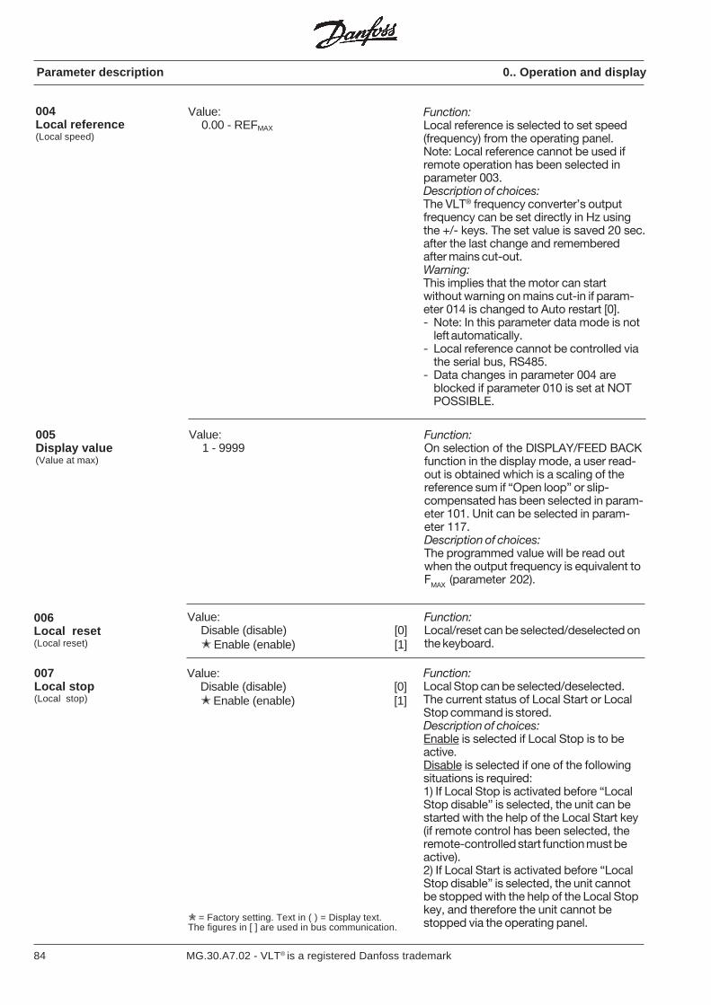
84 MG.30.A7.02 - VLT® is a registered Danfoss trademark
Parameter description 0.. Operation and display
Value:0.00 - REFMAX
004Local reference(Local speed)
Function:Local reference is selected to set speed(frequency) from the operating panel.Note: Local reference cannot be used ifremote operation has been selected inparameter 003.Description of choices:The VLT® frequency converter’s outputfrequency can be set directly in Hz usingthe +/- keys. The set value is saved 20 sec.after the last change and rememberedafter mains cut-out.Warning:This implies that the motor can startwithout warning on mains cut-in if param-eter 014 is changed to Auto restart [0].- Note: In this parameter data mode is not
left automatically.- Local reference cannot be controlled via
the serial bus, RS485.- Data changes in parameter 004 are
blocked if parameter 010 is set at NOTPOSSIBLE.
= Factory setting. Text in ( ) = Display text.The figures in [ ] are used in bus communication.
Value:Disable (disable) [0] Enable (enable) [1]
007Local stop(Local stop)
Value:Disable (disable) [0] Enable (enable) [1]
006Local reset(Local reset)
Function:Local/reset can be selected/deselected onthe keyboard.
Function:Local Stop can be selected/deselected.The current status of Local Start or LocalStop command is stored.Description of choices:Enable is selected if Local Stop is to beactive.Disable is selected if one of the followingsituations is required:1) If Local Stop is activated before “LocalStop disable” is selected, the unit can bestarted with the help of the Local Start key(if remote control has been selected, theremote-controlled start function must beactive).2) If Local Start is activated before “LocalStop disable” is selected, the unit cannotbe stopped with the help of the Local Stopkey, and therefore the unit cannot bestopped via the operating panel.
005Display value(Value at max)
Function:On selection of the DISPLAY/FEED BACKfunction in the display mode, a user read-out is obtained which is a scaling of thereference sum if “Open loop” or slip-compensated has been selected in param-eter 101. Unit can be selected in param-eter 117.Description of choices:The programmed value will be read outwhen the output frequency is equivalent toFMAX (parameter 202).
Value:1 - 9999
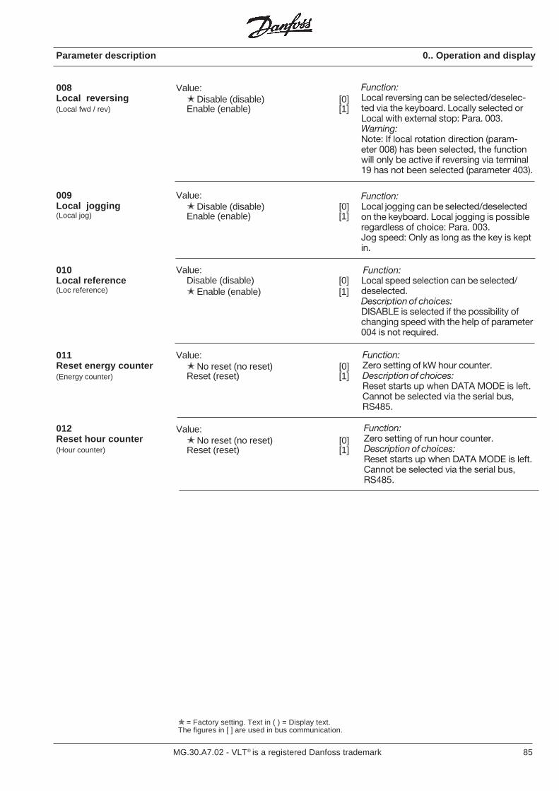
85MG.30.A7.02 - VLT® is a registered Danfoss trademark
Parameter description 0.. Operation and display
008Local reversing(Local fwd / rev)
Function:Local reversing can be selected/deselec-ted via the keyboard. Locally selected orLocal with external stop: Para. 003.Warning:Note: If local rotation direction (param-eter 008) has been selected, the functionwill only be active if reversing via terminal19 has not been selected (parameter 403).
= Factory setting. Text in ( ) = Display text.The figures in [ ] are used in bus communication.
Value: Disable (disable) [0]Enable (enable) [1]
011Reset energy counter(Energy counter)
Value: No reset (no reset) [0]Reset (reset) [1]
009Local jogging(Local jog)
Value: Disable (disable) [0]Enable (enable) [1]
Function:Local jogging can be selected/deselectedon the keyboard. Local jogging is possibleregardless of choice: Para. 003.Jog speed: Only as long as the key is keptin.
010Local reference(Loc reference)
Value:Disable (disable) [0] Enable (enable) [1]
Function:Zero setting of kW hour counter.Description of choices:Reset starts up when DATA MODE is left.Cannot be selected via the serial bus,RS485.
012Reset hour counter(Hour counter)
Function:Zero setting of run hour counter.Description of choices:Reset starts up when DATA MODE is left.Cannot be selected via the serial bus,RS485.
Value: No reset (no reset) [0]Reset (reset) [1]
Function:Local speed selection can be selected/deselected.Description of choices:DISABLE is selected if the possibility ofchanging speed with the help of parameter004 is not required.
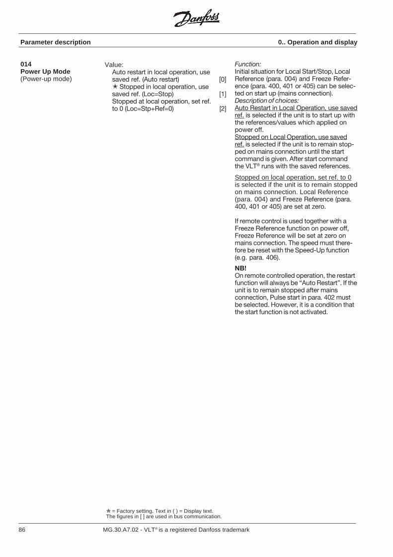
86 MG.30.A7.02 - VLT® is a registered Danfoss trademark
Parameter description 0.. Operation and display
Function:Initial situation for Local Start/Stop, LocalReference (para. 004) and Freeze Refer-ence (para. 400, 401 or 405) can be selec-ted on start up (mains connection).Description of choices:Auto Restart in Local Operation, use savedref. is selected if the unit is to start up withthe references/values which applied onpower off.Stopped on Local Operation, use savedref. is selected if the unit is to remain stop-ped on mains connection until the startcommand is given. After start commandthe VLT® runs with the saved references.
Stopped on local operation, set ref. to 0is selected if the unit is to remain stoppedon mains connection. Local Reference(para. 004) and Freeze Reference (para.400, 401 or 405) are set at zero.
If remote control is used together with aFreeze Reference function on power off,Freeze Reference will be set at zero onmains connection. The speed must there-fore be reset with the Speed-Up function(e.g. para. 406).
NB!On remote controlled operation, the restartfunction will always be “Auto Restart”. If theunit is to remain stopped after mainsconnection, Pulse start in para. 402 mustbe selected. However, it is a condition thatthe start function is not activated.
Value:Auto restart in local operation, usesaved ref. (Auto restart) [0] Stopped in local operation, usesaved ref. (Loc=Stop) [1]Stopped at local operation, set ref.to 0 (Loc=Stp+Ref=0) [2]
014Power Up Mode(Power-up mode)
= Factory setting. Text in ( ) = Display text.The figures in [ ] are used in bus communication.
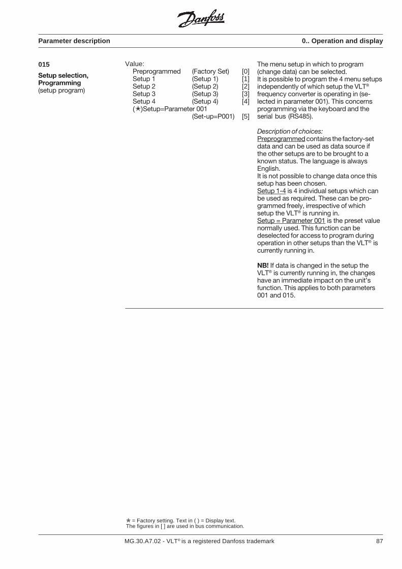
87MG.30.A7.02 - VLT® is a registered Danfoss trademark
Parameter description 0.. Operation and display
015
Setup selection,Programming(setup program)
Value:Preprogrammed (Factory Set) [0]Setup 1 (Setup 1) [1]Setup 2 (Setup 2) [2]Setup 3 (Setup 3) [3]Setup 4 (Setup 4) [4]()Setup=Parameter 001
(Set-up=P001) [5]
The menu setup in which to program(change data) can be selected.It is possible to program the 4 menu setupsindependently of which setup the VLT®
frequency converter is operating in (se-lected in parameter 001). This concernsprogramming via the keyboard and theserial bus (RS485).
Description of choices:Preprogrammed contains the factory-setdata and can be used as data source ifthe other setups are to be brought to aknown status. The language is alwaysEnglish.It is not possible to change data once thissetup has been chosen.Setup 1-4 is 4 individual setups which canbe used as required. These can be pro-grammed freely, irrespective of whichsetup the VLT® is running in.Setup = Parameter 001 is the preset valuenormally used. This function can bedeselected for access to program duringoperation in other setups than the VLT® iscurrently running in.
NB! If data is changed in the setup theVLT® is currently running in, the changeshave an immediate impact on the unit’sfunction. This applies to both parameters001 and 015.
= Factory setting. Text in ( ) = Display text.The figures in [ ] are used in bus communication.
88 MG.30.A7.02 - VLT® is a registered Danfoss trademark
= Factory setting. Text in ( ) = Display text.The figures in [ ] are used in bus communication.
Parameter description 1.. Load and motor
Function:Adjustment of the VLT® frequency convert-er’s U/f characteristics to the load torque’scharacteristics.
Description of choices:Variable torque (VT) low, medium or highis selected if the load is quadratic (centrifu-gal pumps, fans). Choice of torque shouldnormally be made with due considerationof problem-free operation, lowest possibleenergy consumption and least possibleacoustic noise.
Variable torque (VT) low, medium or highwith constant torque (CT) start is selected ifthere is a need for higher break-awaytorque than can be achieved with the threeaforementioned characteristics. The con-stant torque curve is followed until the setreference is reached, after which the vari-able torque characteristics are followed.
Constant torque without start compensa-tion is a load-independent U/f characteristicused for parallel-coupled motors andsynchronous type motors.
Constant torque with start compensation isa load-dependent U/f characteristic wherethe output voltage is increased on increas-ing load (current) to maintain con-stantmagnetization of the motor and to compen-sate for loss in the motor during start.
Constant torque with 4 quadratic slipcompensation has the same function asdescribed for [7] but with slip compensationfor both motor and regenerative op-eration. Slip compensation on regenerativeoperation will usually require use of thebrake option/module. However, the slipcompensation is only active if the functionis selected in parameter 101.
100Load(Load type)
Value:Variable torque low (VT mode-low) [0]Variable torque medium
(VT mode-med) [1]Variable torque high (VT mode-high) [2]VT low CT start (VT low W/CT) [3]VT medium CT start (VT med W/CT) [4]VT high CT start (VT high W/CT) [5]Constant torque (CT mode) [6] Constant torque compensated
(CT with comp) [7]CT 4 quadratic with slip
compensation (CT W 4Q COMP) [8]
89MG.30.A7.02 - VLT® is a registered Danfoss trademark
Parameter description 1.. Load and motor
= Factory setting. Text in ( ) = Display text.The figures in [ ] are used in bus communication.
101Speed control(Speed control)
Value:Open loop (open loop) [0] Slip compensated (slip comp) [1]Closed loop (closed loop) [2]
Function:It is possible to select three different types ofspeed control: open loop, slip compensationand closed loop.Description of choices:Open loop is selected when parallel-coup-led motors or synchronous type motors areused, or if slip compensation is not requiredfor another reason.Slip compensation is selected on normaloperation where constant motor speed isrequired, with varying load.Closed loop is selected if operation withprocess feedback is required. This selectionalso requires selection of feedback type inparameter 114 (current, voltage or pulsa-tions) and setting of PID regulator para-meters (119-125).
102Current limit control(Set cur.limit)
Value: Preprogrammed value
(Program.value) [0]Voltage signal (10 VDC signal) [1]Current signal (20 mA signal) [2]
Function:The current limit can be set in parameter209 and in parameter 412 or 413 with thehelp of a current or voltage signal.Description of choices:Preprogrammed value is selected when afixed set limit for current is required. Thiscurrent limit is set in parameter 209.Voltage signal is selected if the current limitis to be changed during operation with thehelp of a control signal of e.g. 0-10 V onanalogue input 53 (parameter 412) where0 V will correspond to 0% current and 10 Vto the value in parameter 209.Current signal is selected on e.g. 0-20 mAon analogue input 60 (parameter 413).Here 0 mA will correspond to 0% currentlimit and 20 mA will correspond to the valuein parameter 209.
Note:The start conditions (terminals 18 and27) must be present together with aspeed reference (possibly digital ref.parameter 205-208) so that current limitcontrol can be used.
Warning:If the aforementioned conditions existwhen the unit is switched on, the motorcan rotate for up to 5 sec. even thoughthe current limit setting is 0.
90 MG.30.A7.02 - VLT® is a registered Danfoss trademark
Parameter description 1.. Load and motor
103Motor power(Motor power)
Value:(Depending on unit)
Undersize[0] Rated size[1]
Oversize [2]
Function:Selection of connected motor size in kW.This data value is e.g. used for automaticsetting of other motor parameters 107-113.
Description of choices:Read rated motor output in kW from themotor’s type plate and select this value. Ifthis value deviates significantly from thesetting options, select the closest low orhigh value (under- or oversize). The para-meters 107-113 must then be optimizedmanually with standard settings for motorsfrom 0.55-200 kW.
Value:Only for 200-230 V units 200 V [0]220 V [1]230 V [2]Only for 380-415 V units 380 V [3]400 V [4]415 V [5]Only for 440-500 V units 440 V [6]460 V [7]500 V [8]
Select the rated motor output (V) on themotor plate.Parameters 107-113 are changed auto-matically.All values can be addressed via the bus.It is possible to select 440 V motor voltageon a 400 V unit. This can be used tooptimise motor voltage on using e.g. a440 V motor on 415 V mains voltage.If the VLT® types 3060-3250 is factory setto 500 V, so that the lowest motor voltagewhich can be selected is 440 V, this can beadjusted in parameter 650 by changing thedata values to the same VLT® type, but 400V mains voltage.
104Motor voltage (U M,N )(Motor voltage)
105Motor frequency (f N )(Motor freq)
Value:50 Hz (50 Hz) [0]60 Hz (60 Hz) [1]87 Hz (87 Hz) [2]
100 Hz (100 Hz) [3]
Select the rated motor frequency (Hz) on themotor plate. If a motor for 220/230 Vis connected to a 380/415 V frequencyconverter, the default value (50 Hz) must bechanged to 87 Hz. Parameters 107-113 arechanged automatically.
= Factory setting. Text in ( ) = Display text.The figures in [ ] are used in bus communication.
Depending on unit
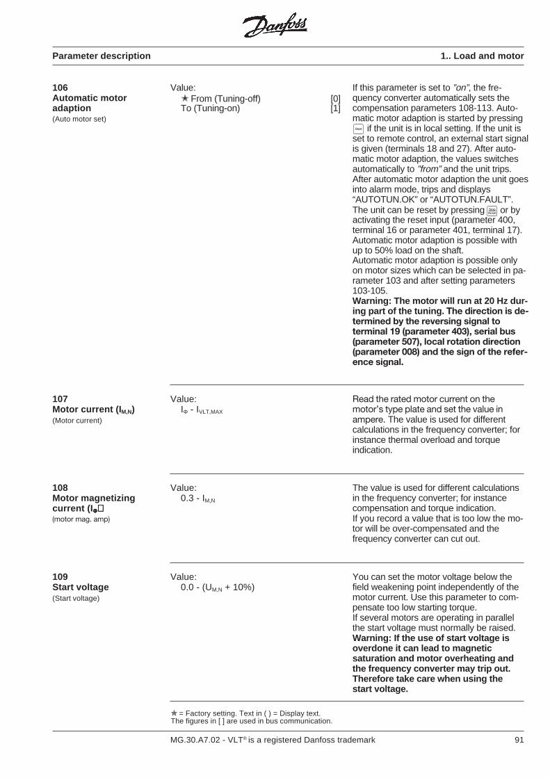
91MG.30.A7.02 - VLT® is a registered Danfoss trademark
Parameter description 1.. Load and motor
106Automatic motoradaption(Auto motor set)
Value: From (Tuning-off) [0]To (Tuning-on) [1]
If this parameter is set to ”on”, the fre-quency converter automatically sets thecompensation parameters 108-113. Auto-matic motor adaption is started by pressing if the unit is in local setting. If the unit isset to remote control, an external start signalis given (terminals 18 and 27). After auto-matic motor adaption, the values switchesautomatically to ”from” and the unit trips.After automatic motor adaption the unit goesinto alarm mode, trips and displays“AUTOTUN.OK” or “AUTOTUN.FAULT”.The unit can be reset by pressing Stop
Reset or byactivating the reset input (parameter 400,terminal 16 or parameter 401, terminal 17).Automatic motor adaption is possible withup to 50% load on the shaft.Automatic motor adaption is possible onlyon motor sizes which can be selected in pa-rameter 103 and after setting parameters103-105.Warning: The motor will run at 20 Hz dur-ing part of the tuning. The direction is de-termined by the reversing signal toterminal 19 (parameter 403), serial bus(parameter 507), local rotation direction(parameter 008) and the sign of the refer-ence signal.
108Motor magnetizingcurrent (I ΦΦΦΦΦ)))))(motor mag. amp)
Value:0.3 - IM,N
The value is used for different calculationsin the frequency converter; for instancecompensation and torque indication.If you record a value that is too low the mo-tor will be over-compensated and thefrequency converter can cut out.
109Start voltage(Start voltage)
Value:0.0 - (UM,N + 10%)
You can set the motor voltage below thefield weakening point independently of themotor current. Use this parameter to com-pensate too low starting torque.If several motors are operating in parallelthe start voltage must normally be raised.Warning: If the use of start voltage isoverdone it can lead to magneticsaturation and motor overheating andthe frequency converter may trip out.Therefore take care when using thestart voltage.
= Factory setting. Text in ( ) = Display text.The figures in [ ] are used in bus communication.
Value:IΦ - IVLT,MAX
Read the rated motor current on themotor’s type plate and set the value inampere. The value is used for differentcalculations in the frequency converter; forinstance thermal overload and torqueindication.
107Motor current (I M,N)(Motor current)
Start
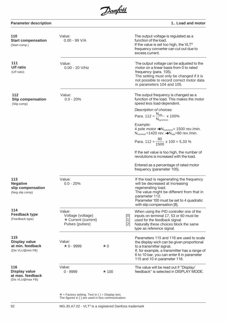
92 MG.30.A7.02 - VLT® is a registered Danfoss trademark
Parameter description 1.. Load and motor
110Start compensation(Start comp.)
Value:0.00 - 99 V/A
The output voltage is regulated as afunction of the load.If the value is set too high, the VLT®
frequency converter can cut out due toexcess current.
= Factory setting. Text in ( ) = Display text.The figures in [ ] are used in bus communication.
111U/f ratio(U/f ratio)
Value:0.00 - 20 V/Hz
The output voltage can be adjusted to themotor on a linear basis from 0 to ratedfrequency (para. 105).The setting must only be changed if it isnot possible to record correct motor datain parameters 104 and 105.
112Slip compensation(Slip comp)
Value:0.0 - 20%
The output frequency is changed as afunction of the load. This makes the motorspeed less load-dependent.
Description of choices:
Para. 112 = x 100%
Example:4 pole motor Nsynchron= 1500 rev./min.Nnominal =1420 rev. Nslip=80 rev./min.
Para. 112 = x 100 = 5,33 %
If the set value is too high, the number ofrevolutions is increased with the load.
Entered as a percentage of rated motorfrequency (parameter 105).
113Negativeslip compensation(Neg slip comp)
Value:0.0 - 20%
114Feedback type(Feedback type)
Parameters 115 and 116 are used to scalethe display wich can be given proportionalto a transmitter signal.If, for example, a transmitter has a range of6 to 10 bar, you can enter 6 in parameter115 and 10 in parameter 116.
The value will be read out if "Display/feedback" is selected in DISPLAY MODE.
If the load is regenerating the frequencywill be decreased at increasingregenerating load.The value might be different from that inparameter 112.Parameter 100 must be set to 4 quadraticwith slip compensation [8].
Value: 0 - 9999 0
115Display valueat min. feedback(Dis VLU@min FB)
Nsynchron
Nslip
150080
Value:0 - 9999 100
116Display valueat max. feedback(Dis VLU@max FB)
Value:Voltage (voltage) [0] Current (current) [1]Pulses (pulses) [2]
When using the PID controller one of theinputs on terminal 17, 53 or 60 must beused for the feedback signal.Naturally these choices block the sametype as reference signal.
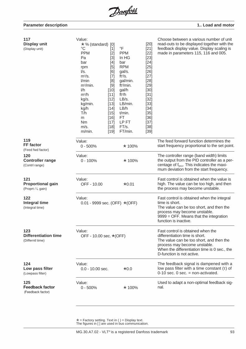
93MG.30.A7.02 - VLT® is a registered Danfoss trademark
Parameter description 1.. Load and motor
117Display unit(Display unit)
Value: % (standard) [0]°C [1]PPM [2]Pa [3]bar [4]rpm [5]l/s. [6]m3/s. [7]l/min [8]m3/min. [9]l/h [10]m3/h [11]kg/s. [12]kg/min. [13]kg/h [14]T/h [15]m [16]Nm [17]m/s. [18]m/min. [19]
[20]°F [21]PPM [22]In HG [23]bar [24]RPM [25]gal/s. [26]ft3/s. [27]gal/min. [28]ft3/min. [29]gal/h [30]ft3/h [31]LB/s. [32]LB/min. [33]LB/h [34]t/min. [35]FT [36]LP FT [37]FT/s. [38]FT/min. [39]
120Controller range(Contrl range)
Value:0 - 100% 100%
The controller range (band width) limitsthe output from the PID controller as a per-centage of fMAX. This indicates the maxi-mum deviation from the start frequency.
121Proportional gain(Proprt / L gain)
Value:OFF - 10.00 0.01
Fast control is obtained when the value ishigh. The value can be too high, and thenthe process may become unstable.
122Integral time(Integral time)
Value:0.01 - 9999 sec. (OFF) (OFF)
Fast control is obtained when the integraltime is short.The value can be too short, and then theprocess may become unstable.9999 = OFF. Means that the integrationfunction is inactive.
123Differentiation time(Differntl time)
Value:OFF - 10.00 sec.(OFF)
Fast control is obtained when thedifferentiation time is short.The value can be too short, and then theprocess may become unstable.When the differentiation time is 0 sec., theD-function is not active.
124Low pass filter(Lowpass filter)
Value:0.0 - 10.00 sec. 0.0
The feedback signal is dampened with alow pass filter with a time constant (τ) of0-10 sec. 0 sec. = non-activated.
125Feedback factor (Feedback factor)
Value:0 - 500% 100%
Used to adapt a non-optimal feedback sig-nal.
Choose between a various number of unitread-outs to be displayed together with thefeedback display value. Display scaling ismade in parameters 115, 116 and 005.
= Factory setting. Text in ( ) = Display text.The figures in [ ] are used in bus communication.
Value:0 - 500% 100%
The feed forward function determines thestart frequency proportional to the set point.
119FF factor(Feed fwd factor)

94 MG.30.A7.02 - VLT® is a registered Danfoss trademark
= Factory setting. Text in ( ) = Display text.The figures in [ ] are used in bus communication.
Parameter description 2.. References and limits
200Frequency range (f RANGE)(Freq range)
Set the maximum of the frequency convert-er’s output frequency range.
201Min. frequency (f MIN)(Min frequency)
The output frequency corresponding to theminimum reference input.
202Max. frequency (f MAX)(Max frequency)
Value:fMIN - fRANGE
The output frequency corresponding to themaximum reference input.
203JOG frequency(JOG frequency)
A preset output frequency. The jog fre-quency can be lower than the minimumoutput frequency recorded in parameter201, but is limited by the fMAX setting inparameter 202. The JOG frequency can beactivated via the keyboard or terminal 29(para. 405).
Value: 0 - 120 Hz [0]0 - 500 Hz [1]
Value:0,0 - fMAX 0,0
Value:0.0 - fRANGE 10 Hz
204Digital reference type(Dig. ref. type)
On selection of sum one of the digital refer-ences (parameters 205-208) as a percent-age of fMAX is added to the other references.
On selection of relative one of the digitalreferences (parameters 205-208) is addedas a percentage of the other references.
On selection of external on/off none of thedigital references is added.
It is possible to switch between the otherreferences and one of the digital referen-ces (parameters 205-208) via terminal 29(parameter 405).
NB: The sign determines only the runningdirection when external to/from is selected.
Other references are the sum of the ana-logue, pulse and bus references.
One of the digital references is selected viaterminals 32 and 33, (para. 406) cf. thetable below.
Terminal 33/ Terminal 320 0 Digital ref. 10 1 Digital ref. 21 0 Digital ref. 31 1 Digital ref. 4
205Digital reference 1(REF. 1 digital)
206Digital reference 2(REF. 2 digital)
207Digital reference 3(REF. 3 digital)
208Digital reference 4(REF. 4 digital)
Value: Sum (sum) [0]Relative (relative) [1]External on / off (ext. on / off) [2]
Value:−100.00% - +100.00% 0of fMAX/analog ref.
Value:−100.00% - +100.00% 0of fMAX/analog ref.
Value:−100.00% - +100.00% 0of fMAX/analog ref.
Value:−100.00% - +100.00% 0of fMAX/analog ref.
Depending on unit
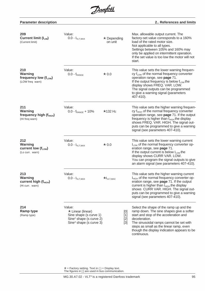
95MG.30.A7.02 - VLT® is a registered Danfoss trademark
209Current limit (I LIM)(Current limit)
Value:0.0 - IVLT,MAX
Max. allowable output current. Thefactory-set value corresponds to a 160%load of the rated motor size.Not applicable to all types.Settings between 105% and 160% mayonly be applied on intermittent operation.If the set value is too low the motor will notstart.
Parameter description 2.. References and limits
210Warningfrequency low (f LOW)(LOW freq warn)
Value:0.0 - fRANGE 0.0
This value sets the lower warning frequen-cy fLOW of the normal frequency converteroperation range, see page 71.If the output frequency is below fLOW thedisplay shows FREQ. VAR. LOW.The signal outputs can be programmedto give a warning signal (parameters407-410).
211Warningfrequency high (f HIGH)(HI freq warn)
Value:0.0 - fRANGE + 10% 132 HZ
This value sets the higher warning frequen-cy fHIGH of the normal frequency converteroperation range, see page 71. If the outputfrequency is higher than fHIGH the displayshows FREQ. VAR. HIGH. The signal out-puts can be programmed to give a warningsignal (see parameters 407-410).
This value sets the lower warning currentILOW of the normal frequency converter op-eration range, see page 71.If the output current is below ILOW thedisplay shows CURR VAR. LOW.You can program the signal outputs to givean alarm signal (see parameters 407-410).
Value:0.0 - IVLT,MAX 0.0
212Warningcurrent low (f LOW)(Lo curr. warn)
213Warningcurrent high (f HIGH)(Hi curr. warn)
Value:0.0 - IVLT,MAX IVLT,MAX
This value sets the higher warning currentIHIGH of the normal frequency converter op-eration range, see page 71. If the outputcurrent is higher than IHIGH the displayshows CURR VAR. HIGH. The signal out-puts can be programmed to give a warningsignal (see parameters 407-410).
214Ramp type(Ramp type)
Value: Linear (linear) [0]Sine shape (s curve 1) [1]Sine2 shape (s curve 2) [2]Sine3 shape (s curve 3) [3]
Select the shape of the ramp up and theramp down. The sine shapes give a softerstart and stop of the acceleration anddeceleration.The sinusoidal ramps cannot be set withsteps as small as the linear ramp, eventhough the display indication appears to becontinuous.
= Factory setting. Text in ( ) = Display text.The figures in [ ] are used in bus communication.
Depending on unit
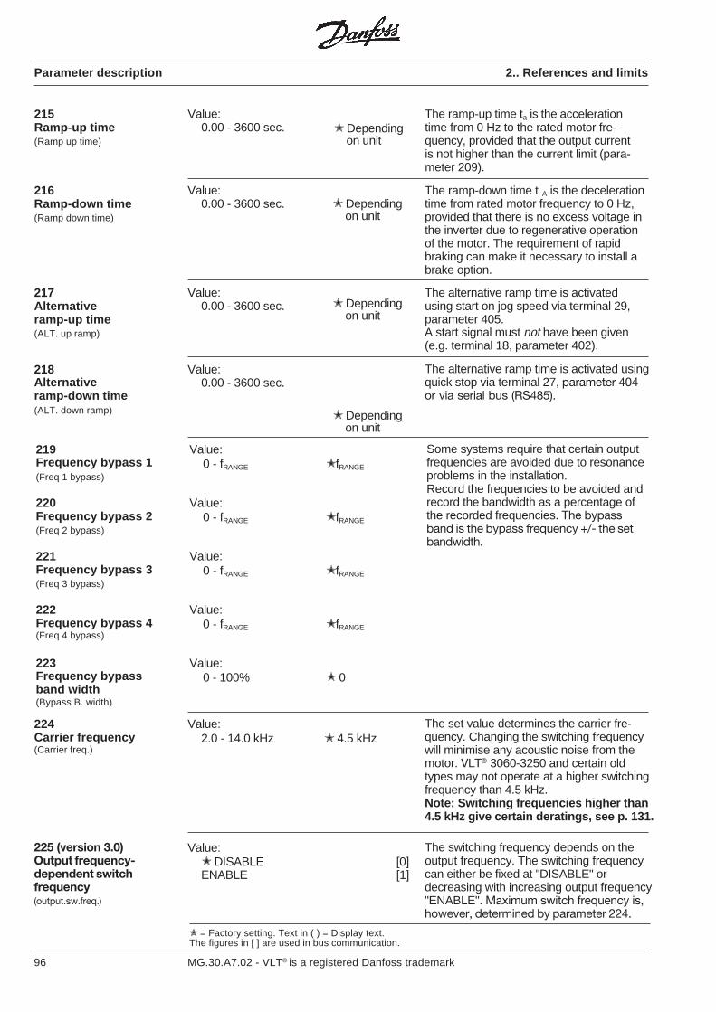
96 MG.30.A7.02 - VLT® is a registered Danfoss trademark
Parameter description 2.. References and limits
= Factory setting. Text in ( ) = Display text.The figures in [ ] are used in bus communication.
Value:0.00 - 3600 sec.
The ramp-up time ta is the accelerationtime from 0 Hz to the rated motor fre-quency, provided that the output currentis not higher than the current limit (para-meter 209).
215Ramp-up time(Ramp up time)
Depending on unit
Depending on unit
225 (version 3.0)Output frequency-dependent switchfrequency(output.sw.freq.)
Value: DISABLE [0]ENABLE [1]
The switching frequency depends on theoutput frequency. The switching frequencycan either be fixed at "DISABLE" ordecreasing with increasing output frequency"ENABLE". Maximum switch frequency is,however, determined by parameter 224.
216Ramp-down time(Ramp down time)
The ramp-down time t−A is the decelerationtime from rated motor frequency to 0 Hz,provided that there is no excess voltage inthe inverter due to regenerative operationof the motor. The requirement of rapidbraking can make it necessary to install abrake option.
Value:0.00 - 3600 sec. Depending
on unit
217Alternativeramp-up time(ALT. up ramp)
Value:0.00 - 3600 sec.
The alternative ramp time is activatedusing start on jog speed via terminal 29,parameter 405.A start signal must not have been given(e.g. terminal 18, parameter 402).
Depending on unit
218Alternativeramp-down time(ALT. down ramp)
Value:0.00 - 3600 sec.
The alternative ramp time is activated usingquick stop via terminal 27, parameter 404or via serial bus (RS485).
219Frequency bypass 1(Freq 1 bypass)
220Frequency bypass 2(Freq 2 bypass)
221Frequency bypass 3(Freq 3 bypass)
222Frequency bypass 4(Freq 4 bypass)
223Frequency bypassband width(Bypass B. width)
Value:0 - fRANGE fRANGE
Value:0 - fRANGE fRANGE
Value:0 - fRANGE fRANGE
Value:0 - fRANGE fRANGE
Value:0 - 100% 0
Some systems require that certain outputfrequencies are avoided due to resonanceproblems in the installation.Record the frequencies to be avoided andrecord the bandwidth as a percentage ofthe recorded frequencies. The bypassband is the bypass frequency +/- the setbandwidth.
224Carrier frequency(Carrier freq.)
Value:2.0 - 14.0 kHz 4.5 kHz
The set value determines the carrier fre-quency. Changing the switching frequencywill minimise any acoustic noise from themotor. VLT® 3060-3250 and certain oldtypes may not operate at a higher switchingfrequency than 4.5 kHz.Note: Switching frequencies higher than4.5 kHz give certain deratings, see p. 131.

97MG.30.A7.02 - VLT® is a registered Danfoss trademark
Parameter description 2.. References and limits
225 (version 3.11)Output frequency-dependent switchfrequency(output.sw.freq.)
Value:Disable (DISABLE) [0]High switching frequency atlow speed [1](HIGH CARR @LO) Low switching frequency atlow speed [2](LOW CARR @LO)
Description of choices:Disable: This gives a fixed switchingfrequency. This is to be chosen, whenusing LC filter (set par. 224 to 4.5 kHz).High switching frequency at low speed:This is to be chosen for variable torque.The function is not available for VLT 3060-3250.0-50% of rated output frequency isswitching frequency = data for par. 224.50-100% of rated output frequencyreduces the switching frequency to 4.5kHz. The function can reduce the acousticmotor noise.Low switching frequency at low speed: Atlow output frequency and current theswitching frequency starts at 1.1 kHz.From 8 Hz the switching frequencyincreases to 4.5 kHz. The functionimproves the motor stability.
Value0.5 Hz-fRANGE 3 HZ
Function:Here the frequency at which the externalbrake is to be released via Relay 01/04 isselected.Description of choices: The electrome-chanical brake must hold the motor untilthe selected frequency is reached, afterwhich the brake is released (voltageimpressed via a relay).If the frequency with connected startsignal comes below the selected value,the voltage to the brake is removed and itagain becomes active.
230Brake cut-out frequency(Brake of freq.)
Function: Here the frequency at which theexternal brake is to be activated by stopvia Relay 01/04 is selected.Description of choices: The electrome-chanical motor brake must first be acti-vated (voltage removed) when the fre-quency during ramp-down reaches the setvalue.
231Brake cut-in frequency(Brake on freq.)
Value0.5 Hz-fRANGE 3 HZ
Value0.0 0.5 X IMAG
Function: Here the minimum current valueto release the brake is selected.Description of choices: The brake isreleased/kept open (voltage impressed viaa relay) when the minimum current value isreached. This function is not active untilexpiry of the time in para. 233.
232Current, Minimum value(Curr. min value)
Value0.00 - 1.00 sec. 0,10 sec.
233Current, Delay time(Curr .dlay. time)
Function: Here the delay time for currentmonitoring is selected (in para. 232).Description of choices: The brake isactivated (de-energized) if the motorcurrent has not reached the value set inpar. 232 after the time delay has run out.If 0.0 sec. is selected, the brake is notreleased until the preselected minimumcurrent is reached.
= Factory setting. Text in ( ) = Display text.The figures in [ ] are used in bus communication.
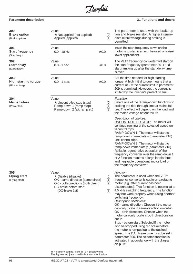
98 MG.30.A7.02 - VLT® is a registered Danfoss trademark
= Factory setting. Text in ( ) = Display text.The figures in [ ] are used in bus communication.
300Brake option(Brake option)
Value: Not applied (not applied) [0]Applied (applied) [1]
The parameter is used with the brake op-tion and brake resistor. A higher interme-diate circuit voltage during braking ispermitted.
Parameter description 3.. Functions and timers
301Start frequency(Start freq.)
Value:0.0 - 10 Hz 0.0
Insert the start frequency at which themotor is to start (can e.g. be used on raise/lower application).
Value:0.0 - 1 sec. 0.0
302Start delay(Start delay)
The VLT® frequency converter will start onthe start frequency (parameter 301) andstart ramping up after the start delay timeis over.
Set the time needed for high startingtorque. A high initial torque means that acurrent of 2 x the current limit in parameter209 is permitted. However, the current islimited by the inverter’s protection limit.
Value:0.0 - 1 sec. 0.0
303High starting torque(HI start torq)
Function:Select one of the 3 ramp-down functions toprolong the ride through time at mains fail-ure. The effect will depend on the load andthe mains voltage before failure.
Description of choices:UNCONTROLLED STOP: The motor willcontinue running at the selected speed un-til control trips.RAMP-DOWN 1: The motor will start toramp down imme-diately (parameter 216)until control trips.RAMP-DOWN 2: The motor will start toramp down immediately (parameter 218).Reliable regenerative operation of thefrequency converter over the ramp down 1or 2 function requires a large inertia forceand negligible operational motor load onthe frequency converter.
Value: Uncontrolled stop (stop) [0]Ramp-down 1 (ramp stop) [1]Ramp-down 2 (alt. ramp st.) [2]
304Mains failure(Power fail)
Function:The parameter is used when the VLT®
frequency converter is cut in on a rotatingmotor (e.g. after current has beendisconnected). This function is optimal at a4.5 kHz switching frequency. The functionmay not work properly when using anotherswitching frequency.Description of choices:OK - same direction: Chosen if the motorcan only rotate in same direction on cut-in.OK - both directions: Chosen when themotor can only rotate in both directions oncut-in.Stop - before start: Selected if the motoris to be stopped using d.c brake beforethe motor is ramped up to the desiredspeed. The D.C. brake time must be set inparameter 306. The selected function isactivated in accordance with the diagramon p. 72.
Value: Disable (disable) [0]OK - same direction (same direct) [1]OK - both directions (both direct) [2]DC-brake before start
(DC-brake 1st) [3]
305Flying start(Flying start)
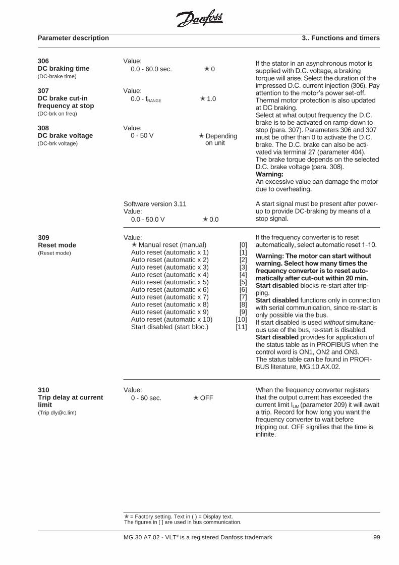
99MG.30.A7.02 - VLT® is a registered Danfoss trademark
Parameter description 3.. Functions and timers
Value:0.0 - 60.0 sec. 0
Value:0.0 - fRANGE 1.0
Value:0 - 50 V
306DC braking time(DC-brake time)
307DC brake cut-infrequency at stop(DC-brk on freq)
308DC brake voltage(DC-brk voltage)
= Factory setting. Text in ( ) = Display text.The figures in [ ] are used in bus communication.
Depending on unit
If the stator in an asynchronous motor issupplied with D.C. voltage, a brakingtorque will arise. Select the duration of theimpressed D.C. current injection (306). Payattention to the motor’s power set-off.Thermal motor protection is also updatedat DC braking.Select at what output frequency the D.C.brake is to be activated on ramp-down tostop (para. 307). Parameters 306 and 307must be other than 0 to activate the D.C.brake. The D.C. brake can also be acti-vated via terminal 27 (parameter 404).The brake torque depends on the selectedD.C. brake voltage (para. 308).Warning:An excessive value can damage the motordue to overheating.
A start signal must be present after power-up to provide DC-braking by means of astop signal.
Software version 3.11Value:
0.0 - 50.0 V 0.0
If the frequency converter is to resetautomatically, select automatic reset 1-10.
Warning: The motor can start withoutwarning. Select how many times thefrequency converter is to reset auto-matically after cut-out within 20 min.Start disabled blocks re-start after trip-ping.Start disabled functions only in connectionwith serial communication, since re-start isonly possible via the bus.If start disabled is used without simultane-ous use of the bus, re-start is disabled.Start disabled provides for application ofthe status table as in PROFIBUS when thecontrol word is ON1, ON2 and ON3.The status table can be found in PROFI-BUS literature, MG.10.AX.02.
Value: Manual reset (manual) [0]Auto reset (automatic x 1) [1]Auto reset (automatic x 2) [2]Auto reset (automatic x 3) [3]Auto reset (automatic x 4) [4]Auto reset (automatic x 5) [5]Auto reset (automatic x 6) [6]Auto reset (automatic x 7) [7]Auto reset (automatic x 8) [8]Auto reset (automatic x 9) [9]Auto reset (automatic x 10) [10]Start disabled (start bloc.) [11]
309Reset mode(Reset mode)
Value:0 - 60 sec. OFF
When the frequency converter registersthat the output current has exceeded thecurrent limit ILIM (parameter 209) it will awaita trip. Record for how long you want thefrequency converter to wait beforetripping out. OFF signifies that the time isinfinite.
310Trip delay at currentlimit(Trip [email protected])

100 MG.30.A7.02 - VLT® is a registered Danfoss trademark
Parameter description 3.. Functions and timers
= Factory setting. Text in ( ) = Display text.The figures in [ ] are used in bus communication.
311Trip delay at inverterfault(Trip dly@fault)
Value:0 - 35 sec.
Software version 3.11:Under voltage fixed 25 sec.Over voltage 0 sec.
When the frequency converter registers anover- or under-voltage in the inverter it willawait a final trip. Record for how long youwant the frequency converter to waitbeforetripping out.
Note: If this value is reduced from thefactory setting, the unit may report a faultat Power on (undervoltage).
Depending on unit
313Motor check(Motor check)
Value: Off (OFF) [0]On (ON) [1]
If "on" is selected the presence of a motoris checked when there is 24 V voltage toterminal 27 and no start command hasbeen given (START, START REV. orJOG). If a motor is not connected, the mes-sage NO MOTOR is shown. This functionis not found for VLT® types 3032-3052, 230V, and VLT® types 3060-3250.
312Max. auto restart time(Auto restart t)
Value:0 - 10 sec. 5 sec.
Sets the max. time allowed for auto restartbefore a final trip, if selected in para. 309.
314Motor pre-heat(Motor pre-heat)
Value: Off (OFF) [0]On (ON) [1]
If "on" is selected the motor will be pre-heated by a DC current when motorcoasting is permitted (terminal 27 = on)and no start command has been given(START, START REV. or JOG). This func-tion is not found for VLT® types 3032-3052,230 V, and VLT® types 3060-3250.
315Motor thermalprotection(Motor thermal)
Value: Off (OFF) [0]Warning 1 (warning 1) [1]Trip 1 (trip 1) [2]Warning 2 (warning 2) [3]Trip 2 (trip 2) [4]Warning 3 (warning 3) [5]Trip 3 (trip 3) [6]Warning 4 (warning 4) [7]Trip 4 (trip 4) [8]
The frequency converter calculateswhether the motor temperature exceedsthe permissible limits. The calculation isbased on 1.16 x rated motor current (setin parameter 107). Four separate calcula-tions are possible, so that one can bechosen for each setup or the samecalculation can be used in severalsetups. Select off if you do not wanteither warning or trip.Select warning only if you want a warningin the display when the motor is overheating.You can also program the frequency con-verter to give a warning signal via thesignal outputs (parameters 407-410).Select “trip” if trip is required when the motoris overloaded.You can also program the frequency con-verter to give a alarm signal via the signaloutputs (parameters 407-410). See graphon page 130.
Value:0.00 - 10.00 sec. 0.00
Value:0.00 - 10.00 sec. 0.00
The delay timers will influence the switchin/out delay of the relay associated with ter-minals 01-02-03.
316Relay ON-delay(Relay on delay)
317Relay OFF-delay(Relay off dela)
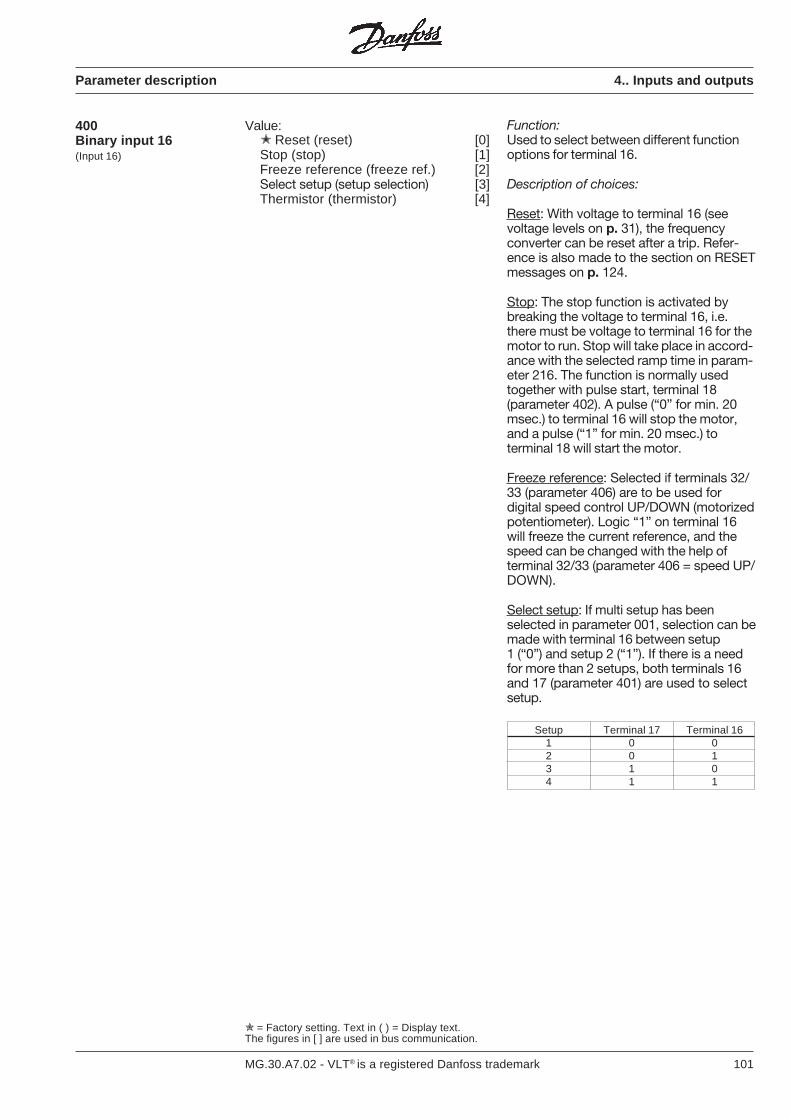
101MG.30.A7.02 - VLT® is a registered Danfoss trademark
= Factory setting. Text in ( ) = Display text.The figures in [ ] are used in bus communication.
Parameter description 4.. Inputs and outputs
400Binary input 16(Input 16)
Value: Reset (reset) [0]Stop (stop) [1]Freeze reference (freeze ref.) [2]Select setup (setup selection) [3]Thermistor (thermistor) [4]
Function:Used to select between different functionoptions for terminal 16.
Description of choices:
Reset: With voltage to terminal 16 (seevoltage levels on p. 31), the frequencyconverter can be reset after a trip. Refer-ence is also made to the section on RESETmessages on p. 124.
Stop: The stop function is activated bybreaking the voltage to terminal 16, i.e.there must be voltage to terminal 16 for themotor to run. Stop will take place in accord-ance with the selected ramp time in param-eter 216. The function is normally usedtogether with pulse start, terminal 18(parameter 402). A pulse (“0” for min. 20msec.) to terminal 16 will stop the motor,and a pulse (“1” for min. 20 msec.) toterminal 18 will start the motor.
Freeze reference: Selected if terminals 32/33 (parameter 406) are to be used fordigital speed control UP/DOWN (motorizedpotentiometer). Logic “1” on terminal 16will freeze the current reference, and thespeed can be changed with the help ofterminal 32/33 (parameter 406 = speed UP/DOWN).
Select setup: If multi setup has beenselected in parameter 001, selection can bemade with terminal 16 between setup1 (“0”) and setup 2 (“1”). If there is a needfor more than 2 setups, both terminals 16and 17 (parameter 401) are used to selectsetup.
Setup Terminal 17 Terminal 161 0 02 0 13 1 04 1 1
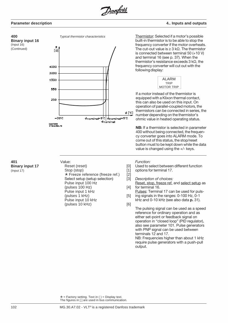
102 MG.30.A7.02 - VLT® is a registered Danfoss trademark
Typical thermistor characteristics Thermistor: Selected if a motor’s possiblebuilt-in thermistor is to be able to stop thefrequency converter if the motor overheats.The cut-out value is ≥ 3 kΩ. The thermistoris connected between terminal 50 (+10 V)and terminal 16 (see p. 37). When thethermistor’s resistance exceeds 3 kΩ, thefrequency converter will cut out with thefollowing display:
If a motor instead of the thermistor isequipped with a Klixon thermal contact,this can also be used on this input. Onoperation of parallel-coupled motors, thethermistors can be connected in series, thenumber depending on the thermistor’sohmic value in heated operating status.
NB: If a thermistor is selected in parameter400 without being connected, the frequen-cy converter goes into ALARM mode. Tocome out of this status, the stop/resetbutton must to be kept down while the datavalue is changed using the +/- keys.
400Binary input 16(Input 16)(Continued)
Parameter description 4.. Inputs and outputs
Value:Reset (reset) [0]Stop (stop) [1] Freeze reference (freeze ref.) [2]Select setup (setup selection) [3]Pulse input 100 Hz(pulses 100 Hz) [4]Pulse input 1 kHz(pulses 1 kHz) [5]Pulse input 10 kHz(pulses 10 kHz) [6]
401Binary input 17(Input 17)
Function:Used to select between different functionoptions for terminal 17.
Description of choices:Reset, stop, freeze ref. and select setup asfor terminal 16.Pulses: Terminal 17 can be used for puls-ing signals in the ranges: 0-100 Hz, 0-1kHz and 0-10 kHz (see also data p. 31).
The pulsing signal can be used as a speedreference for ordinary operation and aseither set-point or feedback signal onoperation in “closed loop” (PID regulator),also see parameter 101. Pulse generatorswith PNP signal can be used betweenterminals 12 and 17.NB: Frequencies higher than about 1 kHzrequire pulse generators with a push-pulloutput.
ALARMTRIP
MOTOR TRIP
= Factory setting. Text in ( ) = Display text.The figures in [ ] are used in bus communication.
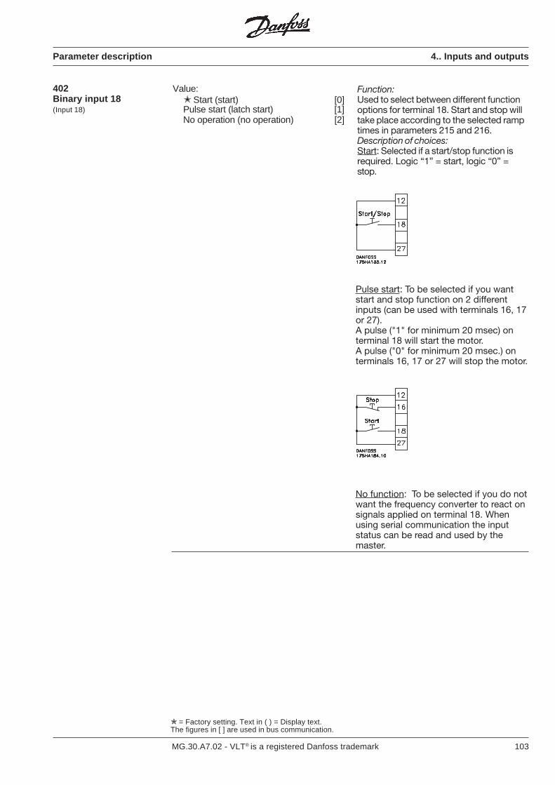
103MG.30.A7.02 - VLT® is a registered Danfoss trademark
Parameter description 4.. Inputs and outputs
402Binary input 18(Input 18)
= Factory setting. Text in ( ) = Display text.The figures in [ ] are used in bus communication.
Value: Start (start) [0]Pulse start (latch start) [1]No operation (no operation) [2]
Function:Used to select between different functionoptions for terminal 18. Start and stop willtake place according to the selected ramptimes in parameters 215 and 216.Description of choices:Start: Selected if a start/stop function isrequired. Logic “1” = start, logic “0” =stop.
Pulse start: To be selected if you wantstart and stop function on 2 differentinputs (can be used with terminals 16, 17or 27).A pulse ("1" for minimum 20 msec) onterminal 18 will start the motor.A pulse ("0" for minimum 20 msec.) onterminals 16, 17 or 27 will stop the motor.
No function: To be selected if you do notwant the frequency converter to react onsignals applied on terminal 18. Whenusing serial communication the inputstatus can be read and used by themaster.
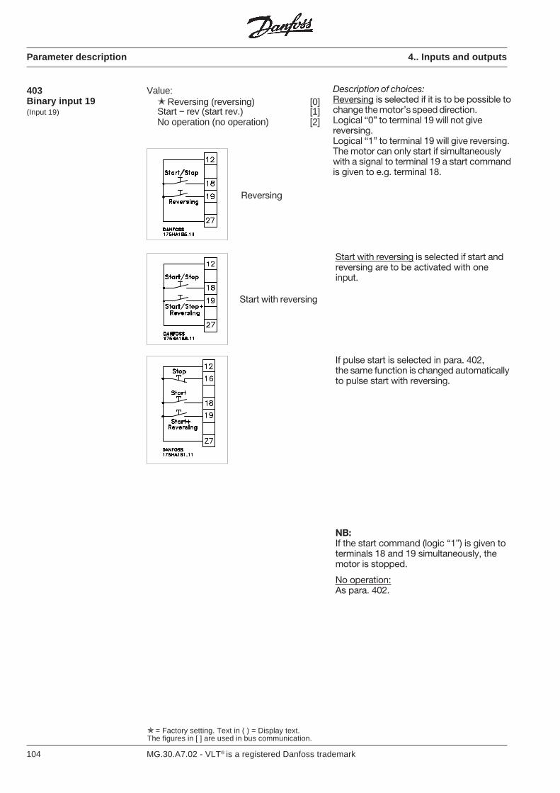
104 MG.30.A7.02 - VLT® is a registered Danfoss trademark
Parameter description 4.. Inputs and outputs
Description of choices:Reversing is selected if it is to be possible tochange the motor’s speed direction.Logical “0” to terminal 19 will not givereversing.Logical “1” to terminal 19 will give reversing.The motor can only start if simultaneouslywith a signal to terminal 19 a start commandis given to e.g. terminal 18.
= Factory setting. Text in ( ) = Display text.The figures in [ ] are used in bus communication.
Value: Reversing (reversing) [0]Start − rev (start rev.) [1]No operation (no operation) [2]
403Binary input 19(Input 19)
Reversing
Start with reversing
Start with reversing is selected if start andreversing are to be activated with oneinput.
If pulse start is selected in para. 402,the same function is changed automaticallyto pulse start with reversing.
NB:If the start command (logic “1”) is given toterminals 18 and 19 simultaneously, themotor is stopped.
No operation:As para. 402.
105MG.30.A7.02 - VLT® is a registered Danfoss trademark
Parameter description 4.. Inputs and outputs
= Factory setting. Text in ( ) = Display text.The figures in [ ] are used in bus communication.
404Terminal 27 Stop(input 27)
Value: Free-wheeling stop(free-wheeling stop) [0]Quick stop (quick stop) [1]D.c. brake (D.C. brake) [2]Reset and free-wheeling stop(reset & fws) [3]Stop (stop - press) [4]
Function:Used to select between different functionoptions for terminal 27.
NB: The motor can only operate if terminal27 is logical “1”. However, this can bedeselected by using serial communication.
Description of choices:Free-wheeling stop: Selected if the fre-quency converter is to “release” the motorwhich then runs freely until it stops. Logical“0” will lead to free-wheeling stop.
Quick stop: Selected if the motor is to bestopped according to alternative ramp timein parameter 218. Logical “0” will meanquick stop.
D.c. brake: Selected if the motor is to bestopped by impressing a D.C. voltage tothe motor for a certain period as selectedin parameters 306 and 308. The function isonly active when the value in parameters306 and 308 is different from 0. Logical “0”will lead to D.C. braking.
Reset and free-wheeling stop: Selectedwhen free-wheeling stop is to be activated(see under free-wheeling stop at the top ofthis description) and reset (see descriptionof reset in parameters 400, 401), simulta-neously.
Logic “0” will mean reset and free-wheel-ing stop.
Stop: Selected if the frequency converteris to be stopped (see description of stop inparameters 400, 401). Logical “0” willmean stop.
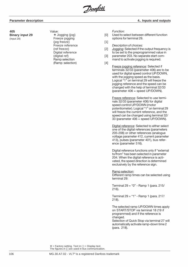
106 MG.30.A7.02 - VLT® is a registered Danfoss trademark
= Factory setting. Text in ( ) = Display text.The figures in [ ] are used in bus communication.
Function:Used to select between different functionoptions for terminal 29.
Description of choices:Jogging: Selected if the output frequency isto be set to the preprogrammed value inparameter 203. No separate start com-mand to activate jogging is required.
Freeze jogging reference: Selected ifterminals 32/33 (parameter 406) are to beused for digital speed control UP/DOWN,with the jogging speed as the basis.Logical “1” on terminal 29 will freeze thejogging reference and the speed can bechanged with the help of terminal 32/33(parameter 406 = speed UP/DOWN).
Freeze reference: Selected to use termi-nals 32/33 (parameter 406) for digitalspeed control UP/DOWN (motorpotentiometer). Logical “1” on terminal 29will freeze the current reference, and thespeed can be changed using terminal 32/33 (parameter 406 = speed UP/DOWN).
Digital reference: Selected to either selectone of the digital references (parameters205-208) or other references (analoguevoltage parameter 412, current parameter413), pulses (parameter 401), bus refer-ence (parameter 516).
Digital reference functions only if “externalto/from” has been selected in parameter204. When the digital reference is acti-vated, the speed direction is determinedexclusively by the reference sign.
Ramp selection:Different ramp times can be selected usingterminal 29:
Terminal 29 = “0” - Ramp 1 (para. 215/216).
Terminal 29 = “1” - Ramp 1 (para. 217/218).
The selected ramp UP/DOWN times applyon START/STOP via terminal 18 (19 ifprogrammed) and if the reference ischanged.Selection of Quick Stop via terminal 27 willautomatically activate ramp-down time 2(para. 218).
Value: Jogging (jog) [0]Freeze jogging(jog freeze) [1]Freeze reference(ref freeze) [2]Digital reference(digital ref) [3]Ramp selection(Ramp selection) [4]
405Binary input 29(Input 29)
Parameter description 4.. Inputs and outputs

107MG.30.A7.02 - VLT® is a registered Danfoss trademark
Terminal 33 Terminal 32No reference-change 0 0Increase reference 0 1Reduce reference 1 0Reduce reference 1 1
Digital reference Terminal 33 Terminal 321 (parameter 205) 0 02 (parameter 206) 0 13 (parameter 207) 1 04 (parameter 208) 1 1
Speed up/down: Selected for digital speedcontrol up/down (motor potentiometer).The function is only active if Freeze refer-ence/Freeze jogging reference has beenselected in parameters 400, 401 or 405,and the equivalent terminal 16, 17 or 29 is“on” (+24 V). As long as terminal 32 is “1”(+24 V), the output frequency will increasetowards fMAX (parameter 202).For as long as terminal 33 is “1” (+24 V),the output frequency will drop towards fMIN(parameter 201). Terminal 33 is mostsignificant.
Function:Used to select between different functionoptions for terminal 32/33.Description of choices:Selection of digital reference: Selected toselect between 4 different preprogrammedspeed references, with the help of a binarycode according to this table:
Setup Terminal 33 Terminal 321 0 02 0 13 1 04 1 1
406Binary input 32/33(Input 32/33)
Value:Digital reference select
(speed select) [0]Speed up / down (speed up/down) [1]Setup selection (setup select) [2] 4 setup extended (4 setup ext.) [3]
A pulse (logical “1” with duration between20 ms and 500 ms) will cause a speedchange of 0.1 Hz to the output.
Logic “1” for more than 500 ms will causethe output frequency to change accordingto the set ramps (parameters 215 and216).Speed reference can be set even thoughthe unit has stopped (does not apply tofree-wheeling stop, quick stop or D.C.brake on terminal 27). Speed reference isremembered after mains cut-out if it hasbeen constant for at least 15 sec. (Seealso parameter 014).Setup select: If “multi setup” has beenselected in parameter 001, there is achoice between setup 1, setup 2, setup 3,or setup according to this table:
= Factory setting. Text in ( ) = Display text.The figures in [ ] are used in bus communication.
Parameter description 4.. Inputs and outputs
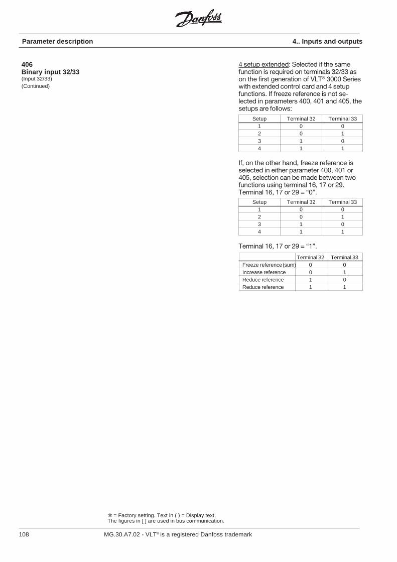
108 MG.30.A7.02 - VLT® is a registered Danfoss trademark
= Factory setting. Text in ( ) = Display text.The figures in [ ] are used in bus communication.
Parameter description 4.. Inputs and outputs
4 setup extended: Selected if the samefunction is required on terminals 32/33 ason the first generation of VLT® 3000 Serieswith extended control card and 4 setupfunctions. If freeze reference is not se-lected in parameters 400, 401 and 405, thesetups are follows:
Setup Terminal 32 Terminal 331 0 02 0 13 1 04 1 1
If, on the other hand, freeze reference isselected in either parameter 400, 401 or405, selection can be made between twofunctions using terminal 16, 17 or 29.Terminal 16, 17 or 29 = “0”.
Setup Terminal 32 Terminal 331 0 02 0 13 1 04 1 1
Terminal 16, 17 or 29 = “1”.
Terminal 32 Terminal 33Freeze reference (sum) 0 0Increase reference 0 1Reduce reference 1 0Reduce reference 1 1
406Binary input 32/33(Input 32/33)(Continued)
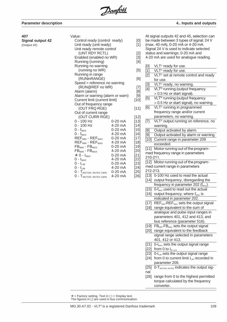
109MG.30.A7.02 - VLT® is a registered Danfoss trademark
Parameter description 4.. Inputs and outputs
407Signal output 42(Output 42)
Value:Control ready (control ready) [0]Unit ready (unit ready) [1]Unit ready remote control
(UNT RDY RCTL) [2]Enabled (enabled no WR) [3]Running (running) [4]Running no warning
(running no WR) [5]Running in range
(RUNinRANGE) [6]Speed = reference no warning
(RUN@REF no WR) [7]Alarm (alarm) [8]Alarm or warning (alarm or warn) [9]Current limit (current limit) [10]Out of frequency range
(OUT FRQ RGE) [11]Out of current range
(OUT CURR RGE) [12]0 - 100 Hz 0-20 mA [13]0 - 100 Hz 4-20 mA [14]0 - fMAX 0-20 mA [15]0 - fMAX 4-20 mA [16]REFMIN - REFMAX 0-20 mA [17]REFMIN - REFMAX 4-20 mA [18]FBMIN - FBMAX 0-20 mA [19]FBMIN - FBMAX 4-20 mA [20] 0 - IMAX 0-20 mA [21]0 - IMAX 4-20 mA [22]0 - ILIM 0-20 mA [23]0 - ILIM 4-20 mA [24]0 - TMOTOR, RATED 100% 0-20 mA [25]0 - TMOTOR, RATED 100% 4-20 mA [26]
= Factory setting. Text in ( ) = Display text.The figures in [ ] are used in bus communication.
At signal outputs 42 and 45, selection canbe made between 3 types of signal: 24 V(max. 40 mA), 0-20 mA or 4-20 mA.Signal 24 V is used to indicate selectedstatus and warnings; 0-20 mA and4-20 mA are used for analogue reading.
[0] VLT® ready for use.[1] VLT® ready for use.[2] VLT® set at remote control and ready
for use.[3] VLT® ready, no warning.[4] VLT® running (output frequency
> 0.5 Hz or start signal).[5] VLT® running (output frequency
> 0.5 Hz or start signal), no warning.[6] VLT® running in programmed
frequency range and/or currentparameters, no warning.
[7] VLT® output running on reference, nowarning.
[8] Output activated by alarm.[9] Output activated by alarm or warning.[10] Current range in parameter 209
exceeded.[11] Motor running out of the program-med frequency range in parameters210-211.[12] Motor running out of the program-med current range in parameters212-213.[13] 0-100 Hz used to read the actual[14] output frequency, disregarding the
frequency in parameter 202 (fMAX).[15] 0-fMAX used to read out the actual[16] output frequency, where fMAX is
indicated in parameter 202.[17] REFMIN-REFMAX sets the output signal[18] range equivalent to the sum of
analogue and pulse input ranges inparameters 401, 412 and 413, andbus reference (parameter 516).
[19] FBMIN-FBMAX sets the output signal[20] range equivalent to the feedback
signal range selected in parameters401, 412 or 413.
[21] 0-IMAX sets the output signal range[22] from 0 to IN x 1.6.
[23] 0-ILIM sets the output signal range[24] from 0 to current limit ILIM recorded in
parameter 209.[25] 0-TMOTOR, RATED indicates the output sig-nal[26] range from 0 to the highest permitted
torque calculated by the frequencyconverter.
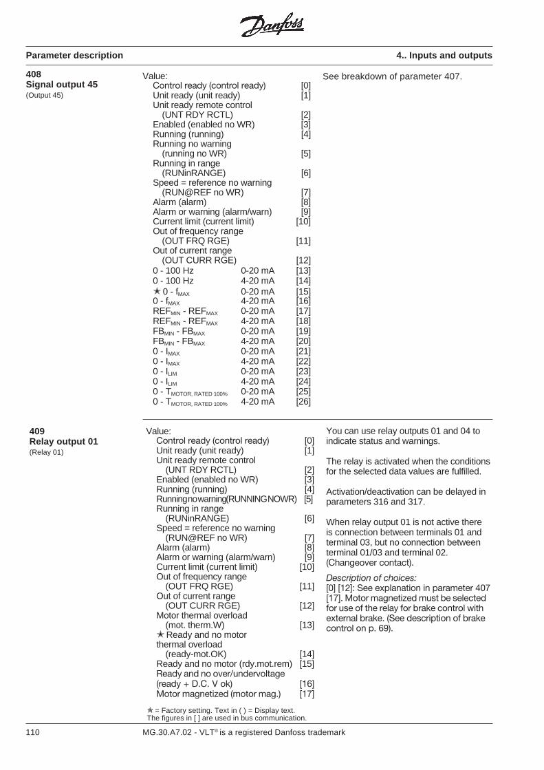
110 MG.30.A7.02 - VLT® is a registered Danfoss trademark
You can use relay outputs 01 and 04 toindicate status and warnings.
The relay is activated when the conditionsfor the selected data values are fulfilled.
Activation/deactivation can be delayed inparameters 316 and 317.
When relay output 01 is not active thereis connection between terminals 01 andterminal 03, but no connection betweenterminal 01/03 and terminal 02.(Changeover contact).
Description of choices:[0] [12]: See explanation in parameter 407[17]. Motor magnetized must be selectedfor use of the relay for brake control withexternal brake. (See description of brakecontrol on p. 69).
Value:Control ready (control ready) [0]Unit ready (unit ready) [1]Unit ready remote control
(UNT RDY RCTL) [2]Enabled (enabled no WR) [3]Running (running) [4]Running no warning (RUNNING NOWR) [5]Running in range
(RUNinRANGE) [6]Speed = reference no warning
(RUN@REF no WR) [7]Alarm (alarm) [8]Alarm or warning (alarm/warn) [9]Current limit (current limit) [10]Out of frequency range
(OUT FRQ RGE) [11]Out of current range
(OUT CURR RGE) [12]Motor thermal overload
(mot. therm.W) [13] Ready and no motorthermal overload
(ready-mot.OK) [14]Ready and no motor (rdy.mot.rem) [15]Ready and no over/undervoltage(ready + D.C. V ok) [16]Motor magnetized (motor mag.) [17]
409Relay output 01(Relay 01)
Value:Control ready (control ready) [0]Unit ready (unit ready) [1]Unit ready remote control
(UNT RDY RCTL) [2]Enabled (enabled no WR) [3]Running (running) [4]Running no warning
(running no WR) [5]Running in range
(RUNinRANGE) [6]Speed = reference no warning
(RUN@REF no WR) [7]Alarm (alarm) [8]Alarm or warning (alarm/warn) [9]Current limit (current limit) [10]Out of frequency range
(OUT FRQ RGE) [11]Out of current range
(OUT CURR RGE) [12]0 - 100 Hz 0-20 mA [13]0 - 100 Hz 4-20 mA [14] 0 - fMAX 0-20 mA [15]0 - fMAX 4-20 mA [16]REFMIN - REFMAX 0-20 mA [17]REFMIN - REFMAX 4-20 mA [18]FBMIN - FBMAX 0-20 mA [19]FBMIN - FBMAX 4-20 mA [20]0 - IMAX 0-20 mA [21]0 - IMAX 4-20 mA [22]0 - ILIM 0-20 mA [23]0 - ILIM 4-20 mA [24]0 - TMOTOR, RATED 100% 0-20 mA [25]0 - TMOTOR, RATED 100% 4-20 mA [26]
408Signal output 45(Output 45)
See breakdown of parameter 407.
= Factory setting. Text in ( ) = Display text.The figures in [ ] are used in bus communication.
Parameter description 4.. Inputs and outputs
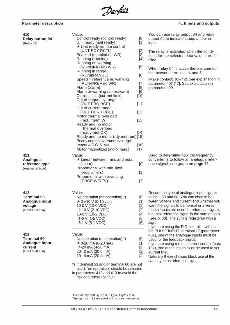
111MG.30.A7.02 - VLT® is a registered Danfoss trademark
= Factory setting. Text in ( ) = Display text.The figures in [ ] are used in bus communication.
Value:Control ready (control ready) [0]Unit ready (unit ready) [1] Unit ready remote control
(UNT RDY RCTL) [2]Enabled (enabled no WR) [3]Running (running) [4]Running no warning
(RUNNING NO WR) [5]Running in range
(RUNinRANGE) [6]Speed = reference no warning
(RUN@REF no WR) [7]Alarm (alarm) [8]Alarm or warning (alarm/warn) [9]Current limit (current limit) [10]Out of frequency range
(OUT FRQ RGE) [11]Out of current range
(OUT CURR RGE) [12]Motor thermal overload
(mot. therm.W) [13]Ready and no motor thermal overload
(ready-mot.OK) [14]Ready and no motor (rdy.mot.rem)[15]Ready and no over/undervoltage(ready + D.C. V ok) [16]Motor magnetized (motor mag.) [17]
410Relay output 04(Relay 04)
You can use relay output 04 and relayoutput 04 to indicate status and warn-ings.
The relay is activated when the condi-tions for the selected data values are ful-filled.
When relay 04 is active there is connec-tion between terminals 4 and 5.
(Make contact). [0]-[12]: See explanation inparameter 407 [17]. See explanation inparameter 409.
Used to determine how the frequencyconverter is to follow an analogue refer-ence signal, see graph on page 71.
Value: Linear between min. and max.
(linear) [0]Proportional with min. limit
(prop w/min.) [1]Proportional with reversing
(PROP W/REV) [2]
411Analoguereference type(Analog ref type)
412Terminal 53Analogue inputvoltage(Input # 53 ana)
Value:No operation (no operation) *) [0] 0-±10 V (0-10 volt) [1]10-0 V (10-0 VDC) [2]2-10 V (2-10 VDC) [3]
10-2 V (10-2 VDC) [4]1-5 V (1-5 VDC) [5]5-1 V (5-1 VDC) [6]
Record the type of analogue input signalsto input 53 and 60. You can choose be-tween voltage and current and whether youwant the signals to be normal or inverse.If both inputs are used for reference signals,the total reference signal is the sum of both.(See p. 68). The sum is registered with asign.If you are using the PID controller withoutthe PULSE INPUT, terminal 17 (parameter401), one of the analogue inputs must beused for the feedback signal.If you are using remote current control (para.102), one of the inputs must be used to setcurrent limit.Naturally these choices block use of thesame type as reference signal.
413Terminal 60Analogue inputcurrent(Input # 60 ana)
Value:No operation (no operation) *) [0] 0-20 mA (0-20 mA) [1]4-20 mA (4-20 mA) [2]
20- 0 mA (20-0 mA) [3]20- 4 mA (20-4 mA) [4]
*) If terminal 53 and/or terminal 60 are notused, “no operation” should be selected
in parameters 412 and 413 to avoid therisk of a reference fault.
Parameter description 4.. Inputs and outputs
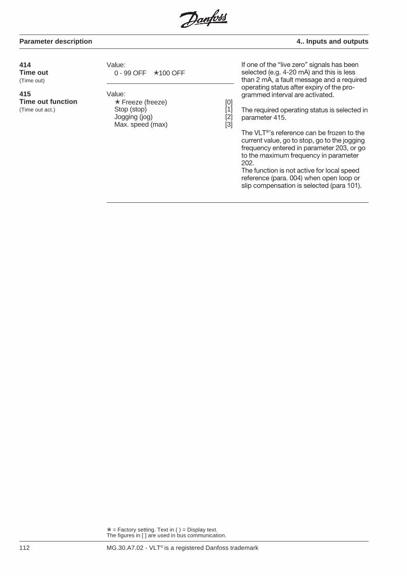
112 MG.30.A7.02 - VLT® is a registered Danfoss trademark
Parameter description 4.. Inputs and outputs
= Factory setting. Text in ( ) = Display text.The figures in [ ] are used in bus communication.
414Time out(Time out)
Value:0 - 99 OFF 100 OFF
If one of the “live zero” signals has beenselected (e.g. 4-20 mA) and this is lessthan 2 mA, a fault message and a requiredoperating status after expiry of the pro-grammed interval are activated.
The required operating status is selected inparameter 415.
The VLT®’s reference can be frozen to thecurrent value, go to stop, go to the joggingfrequency entered in parameter 203, or goto the maximum frequency in parameter202.The function is not active for local speedreference (para. 004) when open loop orslip compensation is selected (para 101).
415Time out function(Time out act.)
Value: Freeze (freeze) [0]Stop (stop) [1]Jogging (jog) [2]Max. speed (max) [3]
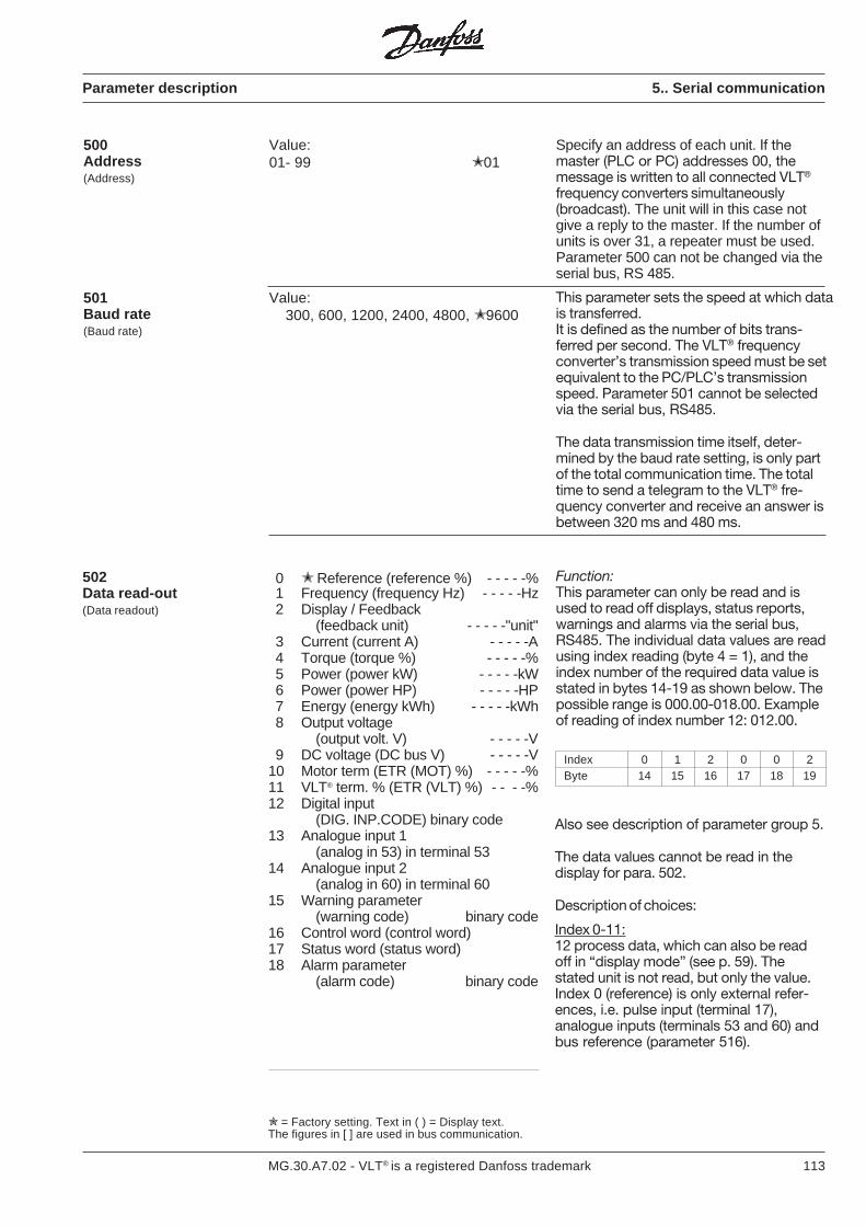
113MG.30.A7.02 - VLT® is a registered Danfoss trademark
500Address(Address)
Value:01- 99 01
Specify an address of each unit. If themaster (PLC or PC) addresses 00, themessage is written to all connected VLT®
frequency converters simultaneously(broadcast). The unit will in this case notgive a reply to the master. If the number ofunits is over 31, a repeater must be used.Parameter 500 can not be changed via theserial bus, RS 485.
501Baud rate(Baud rate)
Value:300, 600, 1200, 2400, 4800, 9600
This parameter sets the speed at which datais transferred.It is defined as the number of bits trans-ferred per second. The VLT® frequencyconverter’s transmission speed must be setequivalent to the PC/PLC’s transmissionspeed. Parameter 501 cannot be selectedvia the serial bus, RS485.
The data transmission time itself, deter-mined by the baud rate setting, is only partof the total communication time. The totaltime to send a telegram to the VLT® fre-quency converter and receive an answer isbetween 320 ms and 480 ms.
502Data read-out(Data readout)
0 Reference (reference %) - - - - -%1 Frequency (frequency Hz) - - - - -Hz2 Display / Feedback
(feedback unit) - - - - -"unit"3 Current (current A) - - - - -A4 Torque (torque %) - - - - -%5 Power (power kW) - - - - -kW6 Power (power HP) - - - - -HP7 Energy (energy kWh) - - - - -kWh8 Output voltage
(output volt. V) - - - - -V9 DC voltage (DC bus V) - - - - -V
10 Motor term (ETR (MOT) %) - - - - -%11 VLT® term. % (ETR (VLT) %) - - - -%12 Digital input
(DIG. INP.CODE) binary code13 Analogue input 1
(analog in 53) in terminal 5314 Analogue input 2
(analog in 60) in terminal 6015 Warning parameter
(warning code) binary code16 Control word (control word)17 Status word (status word)18 Alarm parameter
(alarm code) binary code
Also see description of parameter group 5.
The data values cannot be read in thedisplay for para. 502.
Description of choices:
Index 0-11:12 process data, which can also be readoff in “display mode” (see p. 59). Thestated unit is not read, but only the value.Index 0 (reference) is only external refer-ences, i.e. pulse input (terminal 17),analogue inputs (terminals 53 and 60) andbus reference (parameter 516).
Index 0 1 2 0 0 2Byte 14 15 16 17 18 19
Function:This parameter can only be read and isused to read off displays, status reports,warnings and alarms via the serial bus,RS485. The individual data values are readusing index reading (byte 4 = 1), and theindex number of the required data value isstated in bytes 14-19 as shown below. Thepossible range is 000.00-018.00. Exampleof reading of index number 12: 012.00.
Parameter description 5.. Serial communication
= Factory setting. Text in ( ) = Display text.The figures in [ ] are used in bus communication.
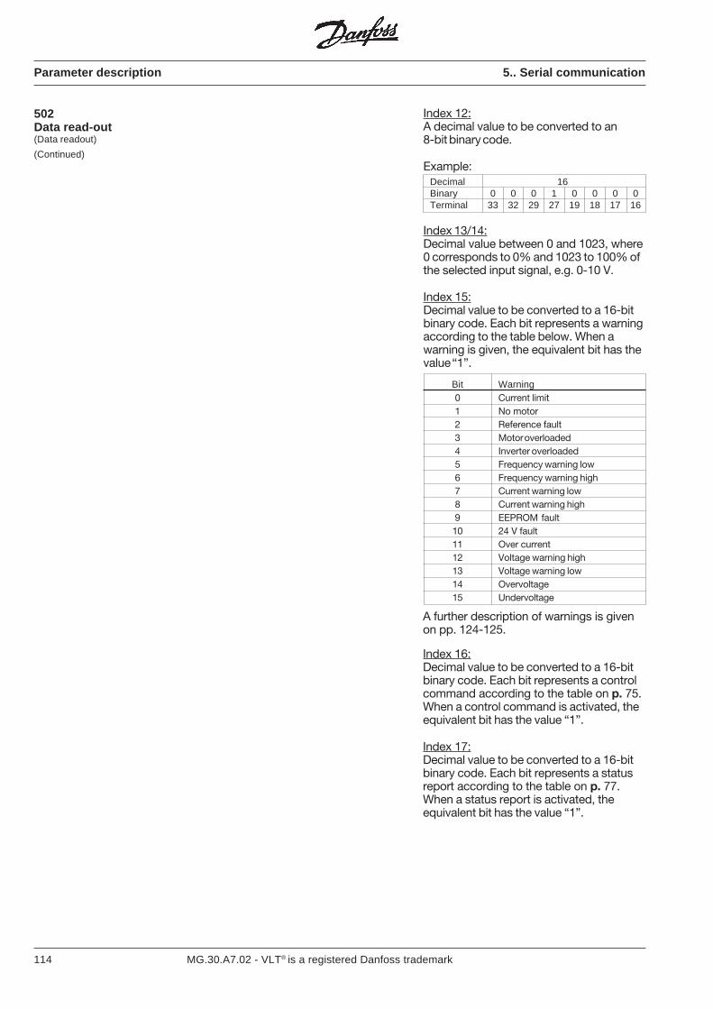
114 MG.30.A7.02 - VLT® is a registered Danfoss trademark
Index 12:A decimal value to be converted to an8-bit binary code.
Example:Decimal 16Binary 0 0 0 1 0 0 0 0Terminal 33 32 29 27 19 18 17 16
Index 13/14:Decimal value between 0 and 1023, where0 corresponds to 0% and 1023 to 100% ofthe selected input signal, e.g. 0-10 V.
Index 15:Decimal value to be converted to a 16-bitbinary code. Each bit represents a warningaccording to the table below. When awarning is given, the equivalent bit has thevalue “1”.
Bit Warning0 Current limit1 No motor2 Reference fault3 Motor overloaded4 Inverter overloaded5 Frequency warning low6 Frequency warning high7 Current warning low8 Current warning high9 EEPROM fault10 24 V fault11 Over current12 Voltage warning high13 Voltage warning low14 Overvoltage15 Undervoltage
A further description of warnings is givenon pp. 124-125.
Index 16:Decimal value to be converted to a 16-bitbinary code. Each bit represents a controlcommand according to the table on p. 75.When a control command is activated, theequivalent bit has the value “1”.
Index 17:Decimal value to be converted to a 16-bitbinary code. Each bit represents a statusreport according to the table on p. 77.When a status report is activated, theequivalent bit has the value “1”.
Parameter description 5.. Serial communication
502Data read-out(Data readout)
(Continued)
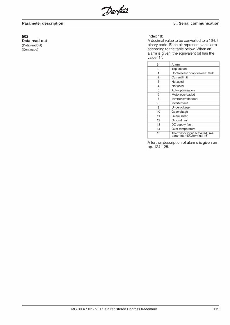
115MG.30.A7.02 - VLT® is a registered Danfoss trademark
Index 18:A decimal value to be converted to a 16-bitbinary code. Each bit represents an alarmaccording to the table below. When analarm is given, the equivalent bit has thevalue “1”.
Bit Alarm0 Trip locked1 Control card or option card fault2 Current limit3 Not used4 Not used5 Auto optimization6 Motor overloaded7 Inverter overloaded8 Inverter fault9 Undervoltage10 Overvoltage11 Overcurrent12 Ground fault13 DC supply fault14 Over temperature15 Thermistor input activated, see
parameter 400/terminal 16
A further description of alarms is given onpp. 124-125.
502Data read-out(Data readout)(Continued)
Parameter description 5.. Serial communication
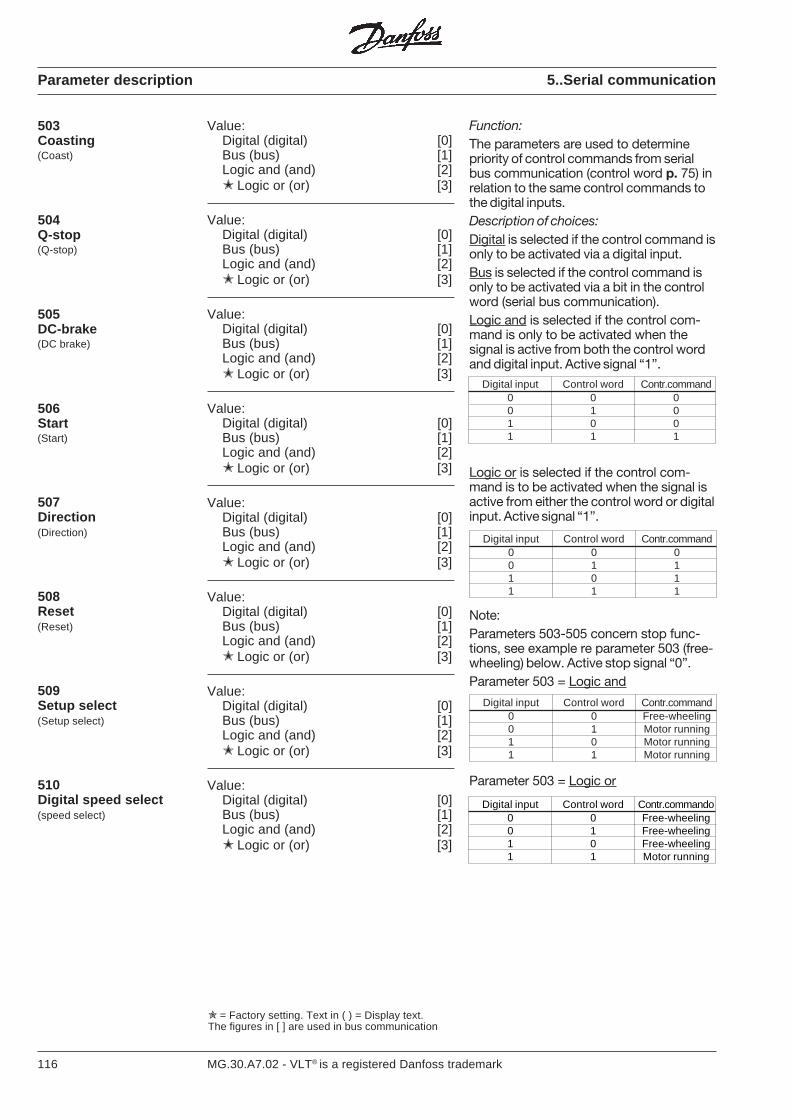
116 MG.30.A7.02 - VLT® is a registered Danfoss trademark
Parameter description
Value:Digital (digital) [0]Bus (bus) [1]Logic and (and) [2] Logic or (or) [3]
503Coasting(Coast)
504Q-stop(Q-stop)
Value:Digital (digital) [0]Bus (bus) [1]Logic and (and) [2] Logic or (or) [3]
505DC-brake(DC brake)
Value:Digital (digital) [0]Bus (bus) [1]Logic and (and) [2] Logic or (or) [3]
506Start(Start)
Value:Digital (digital) [0]Bus (bus) [1]Logic and (and) [2] Logic or (or) [3]
507Direction(Direction)
Value:Digital (digital) [0]Bus (bus) [1]Logic and (and) [2] Logic or (or) [3]
508Reset(Reset)
Value:Digital (digital) [0]Bus (bus) [1]Logic and (and) [2] Logic or (or) [3]
509Setup select(Setup select)
Value:Digital (digital) [0]Bus (bus) [1]Logic and (and) [2] Logic or (or) [3]
510Digital speed select(speed select)
Value:Digital (digital) [0]Bus (bus) [1]Logic and (and) [2] Logic or (or) [3]
5..Serial communication
Function:The parameters are used to determinepriority of control commands from serialbus communication (control word p. 75) inrelation to the same control commands tothe digital inputs.Description of choices:Digital is selected if the control command isonly to be activated via a digital input.Bus is selected if the control command isonly to be activated via a bit in the controlword (serial bus communication).Logic and is selected if the control com-mand is only to be activated when thesignal is active from both the control wordand digital input. Active signal “1”.
Digital input Control word Contr.command0 0 00 1 01 0 01 1 1
Logic or is selected if the control com-mand is to be activated when the signal isactive from either the control word or digitalinput. Active signal “1”.
Digital input Control word Contr.command0 0 00 1 11 0 11 1 1
Note:Parameters 503-505 concern stop func-tions, see example re parameter 503 (free-wheeling) below. Active stop signal “0”.Parameter 503 = Logic and
Digital input Control word Contr.command0 0 Free-wheeling0 1 Motor running1 0 Motor running1 1 Motor running
Parameter 503 = Logic or
Digital input Control word Contr.commando0 0 Free-wheeling0 1 Free-wheeling1 0 Free-wheeling1 1 Motor running
= Factory setting. Text in ( ) = Display text.The figures in [ ] are used in bus communication
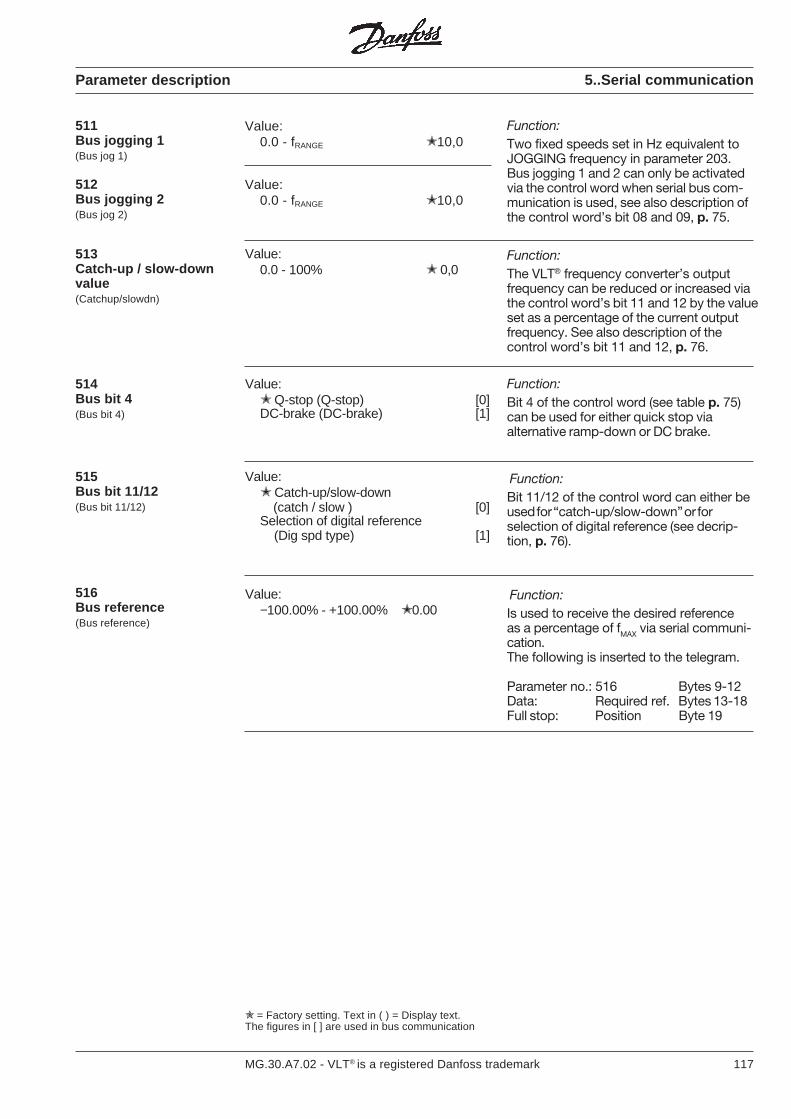
117MG.30.A7.02 - VLT® is a registered Danfoss trademark
511Bus jogging 1(Bus jog 1)
512Bus jogging 2(Bus jog 2)
Value:0.0 - fRANGE 10,0
Value:0.0 - fRANGE 10,0
Function:Two fixed speeds set in Hz equivalent toJOGGING frequency in parameter 203.Bus jogging 1 and 2 can only be activatedvia the control word when serial bus com-munication is used, see also description ofthe control word’s bit 08 and 09, p. 75.
Parameter description 5..Serial communication
= Factory setting. Text in ( ) = Display text.The figures in [ ] are used in bus communication
Function:The VLT® frequency converter’s outputfrequency can be reduced or increased viathe control word’s bit 11 and 12 by the valueset as a percentage of the current outputfrequency. See also description of thecontrol word’s bit 11 and 12, p. 76.
Value:0.0 - 100% 0,0
513Catch-up / slow-downvalue(Catchup/slowdn)
Value: Catch-up/slow-down
(catch / slow ) [0]Selection of digital reference (Dig spd type) [1]
515Bus bit 11/12(Bus bit 11/12)
Value:−100.00% - +100.00% 0.00
516Bus reference(Bus reference)
Function:Is used to receive the desired referenceas a percentage of fMAX via serial communi-cation.The following is inserted to the telegram.
Parameter no.: 516 Bytes 9-12Data: Required ref. Bytes 13-18Full stop: Position Byte 19
Function:Bit 11/12 of the control word can either beused for “catch-up/slow-down” or forselection of digital reference (see decrip-tion, p. 76).
Function:Bit 4 of the control word (see table p. 75)can be used for either quick stop viaalternative ramp-down or DC brake.
Value: Q-stop (Q-stop) [0]DC-brake (DC-brake) [1]
514Bus bit 4(Bus bit 4)
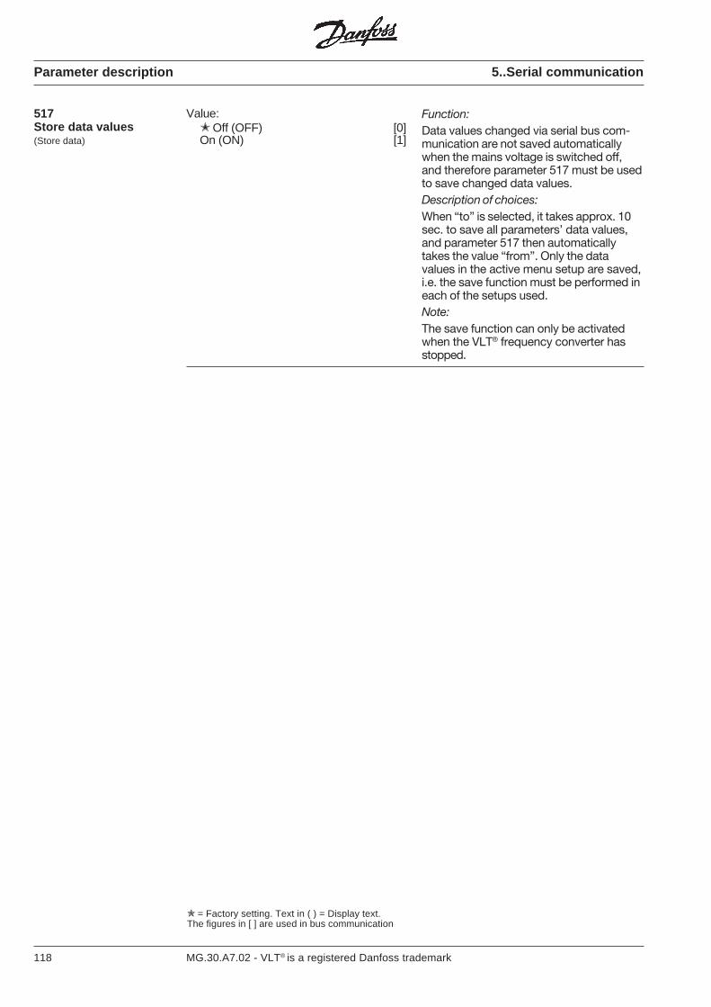
118 MG.30.A7.02 - VLT® is a registered Danfoss trademark
Function:Data values changed via serial bus com-munication are not saved automaticallywhen the mains voltage is switched off,and therefore parameter 517 must be usedto save changed data values.Description of choices:When “to” is selected, it takes approx. 10sec. to save all parameters’ data values,and parameter 517 then automaticallytakes the value “from”. Only the datavalues in the active menu setup are saved,i.e. the save function must be performed ineach of the setups used.Note:The save function can only be activatedwhen the VLT® frequency converter hasstopped.
Parameter description 5..Serial communication
= Factory setting. Text in ( ) = Display text.The figures in [ ] are used in bus communication
517Store data values(Store data)
Value: Off (OFF) [0]On (ON) [1]

119MG.30.A7.02 - VLT® is a registered Danfoss trademark
Function:[Index 000.00-005.00]Display of most important operation data.Description of choices:Display range: Total number of operationhours/running hours/kWh is 0.0-99999(under 10000 with 1 decimal).Number of cut-ins/number of overheatings/number of overvoltages is 0-99999.Serial communication: Total number ofoperation hours/running hours/kWh returnedas floating comma values.Number of cut-ins/number of overheatings/number of overvoltages returned as wholefigures.Total number of operation hours/runninghours/kWh reset automatically after manualinitialization.NB: The stated data is saved every 8 hours.kWh can be reset via parameter 011.Operation hours can be reset via parameter012.Number of cut-ins/number of overheatings/number of overvoltages saved as theyoccur.
600Operation data(Operation data)
601Data log(Data log)
Function:(Index 000.00-019.06)Logging of data for the last few seconds ofoperation.Description of choises:Digital inputs stated in hex code (0-FF).Control word stated in hex code (0-FFFF)for bus operation RS 485, see p. 75.Status word stated in hex code (0-FFFF)for bus operation RS 485, see p. 77.Reference states the control signal as apercentage (0-100%).Frequency out states the unit’s outputfrequency in Hz (0.0-999.9).Phase current is the unit´s output current inA (0.0-999.0).D.C. voltage states the intermediate circuitvoltage in [VDC] (0-999).
0 1 2 3 4 - - 19Digital input [0]Control word [1]Status word [2]Reference % [3]Frequency out [4]Phase current [5]D.C. voltage [6]
Parameter description 6..Service and diagnostics
= Factory setting. Text in ( ) = Display text.The figures in [ ] are used in bus communication
Value:* 0 Total operation hours (tot.hrs xxxx) *)1 Running hours (run hrs xxxx) *)2 kWh (energy xxxx)3 Number of cut-ins (pow.ups xxxx)4 Number of overheatings (ov.temp xxxx)5 Number of overvoltages (ov. volt xxxx)

120 MG.30.A7.02 - VLT® is a registered Danfoss trademark
Parameter description 6..Service and diagnostics
Thermistor input activated, seeparameter 400/terminal 16
602Fault memory(Alarm memory)
0 1 2 3 4 - - 7Fault code [0]Time [1]Value [2]
Function:(Index 000.00-007.02)Storage of data on trip.Description of choices:Fault code indicates the reason for a trip bya figure code between 1 and 15:
= Factory setting. Text in ( ) = Display text.The figures in [ ] are used in bus communication
0 1 2 3 4 - - 19Digital input [0]Control word [1]Status word [2]Reference % [3]Frequency out [4]Phase current [5]D.C. voltage [6]
601Data log(Data log)(Continued)
Fault code Alarm1 Inverter fault2 Overvoltage3 Undervoltage4 Over-current5 Earth fault6 Excess temperature7 Inverter overloaded8 Motor overloaded9 Current limit10 Trip locked11 Control card or option card fault13 Auto-optimization fault14 DC suppley fault15
Time states the value of the total numberof operatin hours on trip. Display range0.0-999.9.
Value states e.g. at what voltage or currenta trip has taken place. Display range 0.0-999.9.On serial communication, the fault code isreturned as a whole number. Time andvalue are returned as floating decimalvalues.8 log values are given (0-7). The lowest lognumber (0) contains the newest/last storeddata value, and the highest log number (7)contains the oldest data value.An alarm can only be represented once.The fault log is reset after manual initializa-tion.Irrespective of which log set is being read,the display will automatically shift to lognumber 0 if a new trip occurs.
20 log values (0-19) are given. The lowestnumber (0) contains the newest/last storeddata value, and the highest log number(19) contains the oldest data value.The data values are logged every 160 msfor as long as the start signal is active.The data log contains the last 20 logvalues (approx. 3.2 s) before a stop signalis given (start not active), or a trip.However, it is possible to scroll through thelog values.The data log is reset during start-up (onmains connection).
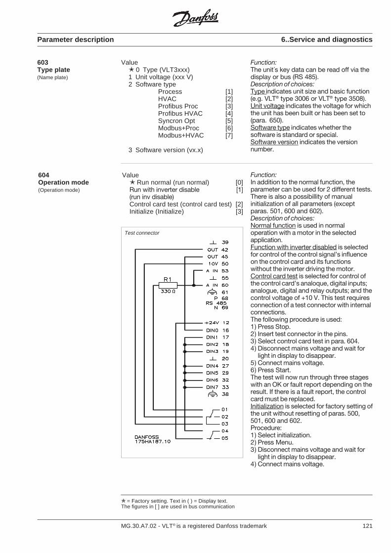
121MG.30.A7.02 - VLT® is a registered Danfoss trademark
603Type plate(Name plate)
Value 0 Type (VLT3xxx)1 Unit voltage (xxx V)2 Software type
Process [1]HVAC [2]Profibus Proc [3]Profibus HVAC [4]Syncron Opt [5]Modbus+Proc [6]Modbus+HVAC [7]
3 Software version (vx.x)
Function:The unit´s key data can be read off via thedisplay or bus (RS 485).Description of choices:Type indicates unit size and basic function(e.g. VLT® type 3006 or VLT® type 3508).Unit voltage indicates the voltage for whichthe unit has been built or has been set to(para. 650).Software type indicates whether thesoftware is standard or special.Software version indicates the versionnumber.
604Operation mode(Operation mode)
Value Run normal (run normal) [0]Run with inverter disable [1](run inv disable)Control card test (control card test) [2]Initialize (Initialize) [3]
Test connector
= Factory setting. Text in ( ) = Display text.The figures in [ ] are used in bus communication
Parameter description 6..Service and diagnostics
Function:In addition to the normal function, theparameter can be used for 2 different tests.There is also a possibillity of manualinitialization of all parameters (exceptparas. 501, 600 and 602).Description of choices:Normal function is used in normaloperation with a motor in the selectedapplication.Function with inverter disabled is selectedfor control of the control signal’s influenceon the control card and its functionswithout the inverter driving the motor.Control card test is selected for control ofthe control card’s analoque, digital inputs;analogue, digital and relay outputs; and thecontrol voltage of +10 V. This test requiresconnection of a test connector with internalconnections.The following procedure is used:1) Press Stop.2) Insert test connector in the pins.3) Select control card test in para. 604.4) Disconnect mains voltage and wait for
light in display to disappear.5) Connect mains voltage.6) Press Start.The test will now run through three stageswith an OK or fault report depending on theresult. If there is a fault report, the controlcard must be replaced.Initialization is selected for factory setting ofthe unit without resetting of paras. 500,501, 600 and 602.Procedure:1) Select initialization.2) Press Menu.3) Disconnect mains voltage and wait for
light in display to disappear.4) Connect mains voltage.
122 MG.30.A7.02 - VLT® is a registered Danfoss trademark
Parameter description 6.. Service and diagnostics
Function:You can have two different displayread-outs in the display at the same time.The extra read-out selected in this para-me-ter will be shown in line 2 of the display.
Description of choices:Standard display is selected for normalreading of e.g. the frequency in Hz in line 1,indication of ’’frequency” in line 2 and indi-cation of status of operation in line 3. Theother data values are selected to read an-other operation value in line 2, so that theaforementioned frequency in line 1 and cur-rent in line 2 simultaneously is possible.There are 14 different data values to selectbetween.
Note that to be able to see both lines si-multaneously, the display must be inDisplay mode.
Value: Standard display (standard disp.) [0]Reference % (reference %) [1]Frequency Hz (frequency Hz) [2]Feedback unit (feedbk 'unit') [3]Current A (current A) [4]Torque % (torque %) [5]Power kW (power kW) [6]HP power (power HP) [7]Energy kWh (energy kWh) [8]Output voltage VLT (out/volt V) [9]DC voltage VLT (DC bus) [10]VLT therm % (ETR (VLT) %) [11]Motor therm % (ETR (MOT) %) [12]Running hours (run hours) [13]Input status "binary code"
(input status) [14]
605Personal display select
Function:Used to indicate which unit the control cardis placed in, in cases where the control cardcannot decide for itself, or to select voltagerange in multi-voltage units if the factorysetting deviates from what is required.
Description of choices:The parameter is used to select the correctVLT® type/size/voltage for VLT® types 3060-3250 and VLT® types 3575-3800, which aremulti-voltage units. If the factory-set voltagedoes not correspond to the voltage in theapplication for which the unit is used, thefollowing procedure is used.
1) Select the required VLT®
type/size/voltage.2) Select parameter 604, data value
initialization.3) Disconnect mains voltage and wait for
the light in the display to disappear.4) Connect mains voltage.
Note that during start-up the displayshows the selected new data.
650VLT type(VLT type)
= Factory setting. Text in ( ) = Display text.The figures in [ ] are used in bus communication.
(Display select)

123MG.30.A7.02 - VLT® is a registered Danfoss trademark
Status messages
Display messages
Status messages appear in the third line ofthe display, see example below:
LOCAL STOP (ENAB STP LOC):“Local” or “local with external stop” hasbeen selected in parameter 003, and “stop”has been activated on the keyboard.
VLT® ready, local (UNIT RDY LOC):“Local” or “local with external stop” hasbeen selected in parameter 003, “free-wheeling stop” in parameter 404, and thereis 0 V to terminal 27.
Local start ok (START LOKAL):
Local operation ok (RUN OK LOCAL):“Local” or “local with external stop” hasbeen selected in parameter 003, and theVLT® frequency converter is running at theset speed reference (parameter 004).
Local jogging (JOG LOCAL):“Local” or “local with external stop” hasbeen selected in parameter 003, and “jog”has been activated on the keyboard.
Local ramp operation (RAMP LOCAL):“Local” or “local with external stop” hasbeen selected in parameter 003, and theoutput frequency changes according to theset ramp times.
Stop (ENAB STOP):“Remote control” has been selected inparameter 003, and the VLT® frequencyconverter has been stopped via the key-board or digital input.
VLT® ready (UNIT READY):“Remote control” has been selected in pa-rameter 003, “free-wheeling stop” in para-meter 404, and there is 0 V to terminal 27.
Start ok (START OK):
Operation ok (RUN OK):“Remote control” has been selected inparameter 003, and the VLT® frequencyconverter is running at the speed refer-ence.
Jogging (JOGGING):“Remote control” has been selected inparameter 003, “jogging” in parameter 405,and there is 24 V to terminal 29.
Ramp operation (RAMPING):“Remote control” has been selected inparameter 003, and the output frequencychanges according to the set ramp times.
Freeze reference (FREEZE.):“Remote control” has been selected inparameter 003, “freeze reference” inparameter 400, 401 or 405, and therespective input (16, 17 or 29) has beenactivated.
Auto optimization (ADPT.TUNING)Adaptive motor tuning is active.
The following status messages are onlyfound when serial communication isused (RS485):
OFF 2 (OFF 2):Bit 01 in the control word is “0”, see p. 77.
OFF 3 (OFF 3):Bit 02 in the control word is “0”, see p. 77.
Start disabled (START INHIB.):Bit 06 in the status word is “1”, see p. 78.
Reference locked (HOLD):Bit 05 in the control word is “0”, see p. 76.
50.0 HzFREQUENCYSTART LOCAL
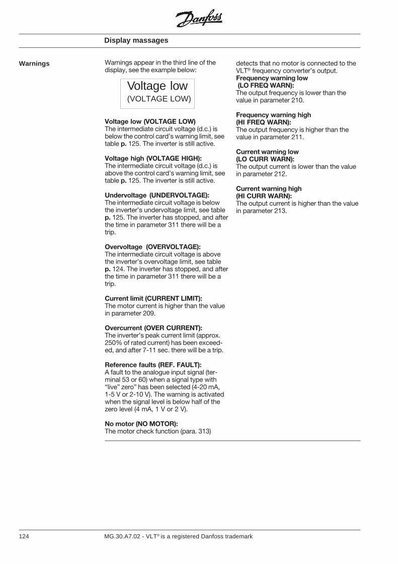
124 MG.30.A7.02 - VLT® is a registered Danfoss trademark
Warnings appear in the third line of thedisplay, see the example below:
Voltage low (VOLTAGE LOW)The intermediate circuit voltage (d.c.) isbelow the control card’s warning limit, seetable p. 125. The inverter is still active.
Voltage high (VOLTAGE HIGH):The intermediate circuit voltage (d.c.) isabove the control card’s warning limit, seetable p. 125. The inverter is still active.
Undervoltage (UNDERVOLTAGE):The intermediate circuit voltage is belowthe inverter’s undervoltage limit, see tablep. 125. The inverter has stopped, and afterthe time in parameter 311 there will be atrip.
Overvoltage (OVERVOLTAGE):The intermediate circuit voltage is abovethe inverter’s overvoltage limit, see tablep. 124. The inverter has stopped, and afterthe time in parameter 311 there will be atrip.
Current limit (CURRENT LIMIT):The motor current is higher than the valuein parameter 209.
Overcurrent (OVER CURRENT):The inverter’s peak current limit (approx.250% of rated current) has been exceed-ed, and after 7-11 sec. there will be a trip.
Reference faults (REF. FAULT):A fault to the analogue input signal (ter-minal 53 or 60) when a signal type with“live” zero” has been selected (4-20 mA,1-5 V or 2-10 V). The warning is activatedwhen the signal level is below half of thezero level (4 mA, 1 V or 2 V).
No motor (NO MOTOR):The motor check function (para. 313)
Warnings
Display massages
Voltage low(VOLTAGE LOW)
detects that no motor is connected to theVLT® frequency converter’s output.Frequency warning low (LO FREQ WARN):The output frequency is lower than thevalue in parameter 210.
Frequency warning high(HI FREQ WARN):The output frequency is higher than thevalue in parameter 211.
Current warning low(LO CURR WARN):The output current is lower than the valuein parameter 212.
Current warning high(HI CURR WARN):The output current is higher than the valuein parameter 213.
125MG.30.A7.02 - VLT® is a registered Danfoss trademark
Display messages
Voltage limits:
Undervoltage 210 400 460 470Voltage warning low 235 440 510 480Voltage warning high 370 665 800 790
(395) (705) (845) (820)Overvoltage 410 730 880 850
(Brake option used,parameter 300)
VLT® 3000 Series3x200/230 V
[VDC]3x380/415 V
[VDC]3x440/500 V
[VDC]
The voltages stated are the VLT®’s intermediate circuit voltage, the equivalent mainsvoltage is the intermediate circuit voltage divided by √2.
Motor overloaded (MOTOR TIME):According to the electronic thermal motorprotection, the motor is too hot. The war-ning only appears if “warning” has been se-lected in parameter 315. See curve p. 130.
Inverter overloaded (INVERT TIME):The electronic thermal inverter protectionreports that the VLT® frequency converter isclose to cutting out due to overload (currenttoo high for too long). The counter forelectronic thermal inverter protection hasreached 98% (100% gives trip).
24 V fault (NO 24 VOLT):24 V voltage supply from power section tocontrol card is absent.
EEPROM fault (EEPROM ERROR):EEPROM fault, data changes are notsaved when the mains voltage is switchedoff.
VLT® 3060-3250[VDC]
Warnings(Continued)
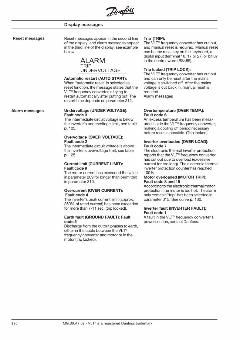
126 MG.30.A7.02 - VLT® is a registered Danfoss trademark
Display massages
Reset messages
Undervoltage (UNDER VOLTAGE):Fault code 3The intermediate circuit voltage is belowthe inverter’s undervoltage limit, see tablep. 125.
Overvoltage (OVER VOLTAGE):Fault code 2The intermediate circuit voltage is abovethe inverter’s overvoltage limit, see tablep. 125.
Current limit (CURRENT LIMIT):Fault code 9The motor current has exceeded the valuein parameter 209 for longer than permittedin parameter 310.
Overcurrent (OVER CURRENT): Fault code 4The inverter’s peak current limit (approx.250% of rated current) has been exceededfor more than 7-11 sec. (trip locked).
Earth fault (GROUND FAULT): Faultcode 5Discharge from the output phases to earth,either in the cable between the VLT®
frequency converter and motor or in themotor (trip locked).
Overtemperature (OVER TEMP.):Fault code 6An excess temperature has been meas-ured inside the VLT® frequency converter,making a cooling off period necessarybefore reset is possible. (Trip locked).
Inverter overloaded (OVER LOAD):Fault code 7The electronic thermal inverter protectionreports that the VLT® frequency converterhas cut out due to overload (excessivecurrent for too long). The electronic thermalinverter protection counter has reached100%.Motor overloaded (MOTOR TRIP):Fault code 8 and 15According to the electronic thermal motorprotection, the motor is too hot. The alarmonly comes if “trip” has been selected inparameter 315. See curve p. 130.
Inverter fault (INVERTER FAULT):Fault code 1A fault in the VLT® frequency converter’spower section, contact Danfoss.
ALARMTRIPUNDERVOLTAGE
Trip (TRIP):The VLT® frequency converter has cut out,and manual reset is required. Manual resetcan be the reset key on the keyboard, adigital input (terminal 16, 17 or 27) or bit 07in the control word (RS485).
Trip locked (TRIP LOCK):The VLT® frequency converter has cut outand can only be reset after the mainsvoltage is switched off. After the mainsvoltage is cut back in, manual reset isrequired.Alarm messages
Reset messages appear in the second lineof the display, and alarm messages appearin the third line of the display, see examplebelow:
Automatic restart (AUTO START):When “automatic reset” is selected asreset function, the message states that theVLT® frequency converter is trying torestart automatically after cutting out. Therestart time depends on parameter 312.
Alarm messages
127MG.30.A7.02 - VLT® is a registered Danfoss trademark
EXCEPTXXXX ERRORPC=XXXX
Display messages
Alarm messages(continued)
• If disabled keypad is pressed:KEY DISABLEDIndicates factory setup.Change parameter 001 to setup 1-4.Or the key is disabled (parameters006-009).
• If data change only possible when thefrequency converter is stopped isattempted: ONLY ON STOP
• If data change is attempted with openLOCK-switch: PROG.LOCKED
• If data change is attempted out ofallowed range: LIMIT
Error messages
Auto optimization ok (TUNING OK):Auto optimization has taken place.
Auto optimization fault(TUNING. FAULT): Fault code 13The reasons for auto optimization fault canbe the following:The connected motor is very small or verylarge in relation to the VLT® frequencyconverter.The motor is loaded more than 50%.The connected motor is a special motor,e.g. a synchronous motor.The fault can be due to electrical noise,e.g. no or poor earth connection to theVLT® frequency converter.The reason can also be attempts at autooptimization on a very small motor in relationto the VLT® frequency converter (5-6undersizes).
The VLT® frequency converter performs aself-test of the control card when the mainsvoltage is connected, giving the followingmessage:
The reason for the fault message is a faulton the control card or possible option card.Contact Danfoss.
TESTINGCONTROL CARDFAULT_XXXX
EXCEPT fault::
Start-up test:
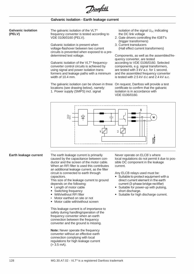
128 MG.30.A7.02 - VLT® is a registered Danfoss trademark
The galvanic isolation of the VLT®
frequency converter is tested according toVDE 0106/0160 (PELV).
Galvanic isolation is present whenvoltage-flashover between two currentcircuits is prevented when exposed to a pre-determined test voltage.
Galvanic isolation of the VLT® frequency-converter control circuits is achieved byusing signal and power isolation trans-formers and leakage paths with a minimumwidth of 10.4 mm.
The galvanic isolation can be shown in threelocations (see drawing below), namely:1. Power supply (SMPS) incl. signal
Galvanic isolation(PELV)
isolation of the signal UDC indicatingthe DC link voltage
2. Gate drivers controlling the IGBT's(trigger transformers)
3. Current transducers(Hall effect current transformers)
Components, as well as the assembled fre-quency converter, are testedaccording to VDE 0106/0160. Selectedcomponents, e.g. signal transformers,are tested with 3 kV a.c. for 1 second,and the assembled frequency converteris tested with 2.5 kV d.c and 2.4 kV a.c.
On request, Danfoss will provide a testcertificate to confirm that the galvanicisolation is in accordance withVDE 0106/0160.
Earth leakage current The earth leakage current is primarilycaused by the capacitance between con-ductor and the screen of the motor cable.When an RFI filter is used this contributesan additional leakage current, as the filtercircuit is connected to earth throughcapacitors.This size of the leakage current to grounddepends on the following:• Length of motor cable• Switching frequency• With/without RFI filter• Motor earthed on site or not• Motor cable with/without screen
This leakage current is of importance tosafety during handling/operation of thefrequency converter when an earthconnection between the frequencyconverter and the ground is missing.
Note: Never operate the frequencyconverter without an effective earthconnection complying with localregulations for high leakage current(> 3.5 mA).
Never operate on ELCB´s wherelocal regulations do not permit it due to pos-sible DC component in the leakagecurrent.
Any ELCB relays used must be:• Suitable to protect equipment with a
direct current element in the earthcurrent (3-phase bridge rectifier)
• Suitable for power-up with pulsing,short discharge.
• Suitable for high discharge current.
Galvanic isolation - Earth leakage current
129MG.30.A7.02 - VLT® is a registered Danfoss trademark
Extreme runningconditions
Short circuitBy means of current measurement in eachof the three motor phases the VLT® 3000Series is protected against short circuits.
A short circuit between two output phaseswill cause overcurrent in the inverter.However, all transistors in the inverter areturned off individually when the short-circuitcurrent exceeds the permitted value.
After 5-10 seconds the driver card turns offthe inverter and the frequency converter willdisplay a fault code.
Earth faultIn case of an earth fault in a motor phasethe inverter is turned off within 5-10 ms.
Switching on the outputThe frequency converter output to the motorcan be cut in/out without any limit.It is not possible to damage the VLT®
frequency converter in any way by cuttingin/out on the output, although fault mes-sages can occur.
Catching a spinning motor (flying start)The frequency converter is able to controla spinning load without stopping it or trip-ping first, e.g. after a mains failure or whena contactor is used on the output with alarge inverter load.It performs this with a speed search whencutting in on a spinning motor (see param-eter 305).
Motor-generated overvoltageThe voltage on the DC link can be increasedwhen the motor acts as a generator. Thistakes place in two cases:1. The load runs the motor (at constant
output frequency from the frequencyconverter), i.e. energy is supplied fromthe load.
2. During deceleration ("ramp-down"),if the moment of inertia is high, thefriction load is low and/or the ramp-down time is short.
The control unit attempts to correct the rampif possible.The inverter turns off to protect the transis-tors and the d.c. bus capacitors when acertain d.c. voltage level is reached.
Mains drop-outDuring a mains drop-out the VLT® frequencyconverter will continue to operate until theDC link voltage drops below the minimumstop level, which is typically 15% below theVLT® frequency converter’s lowest ratedsupply voltage.The time before inverter stop depends onmains voltage before drop-out, and theload of the motor.Ride-through and/or flying start can beprogrammed.
Static overloadWhen the VLT® frequency converter is over-loaded (the current limit ILIM is reached) thecontrol will reduce the output frequency fMin an attempt to reduce the load. If the re-duction of output frequency does not re-duce the load then the control unit’s final tripis released when the output frequency hasreached below 0.5 Hz.
Running-in current limit can be limited(0 - 60 sec.) by parameter 310.
Extreme running conditions
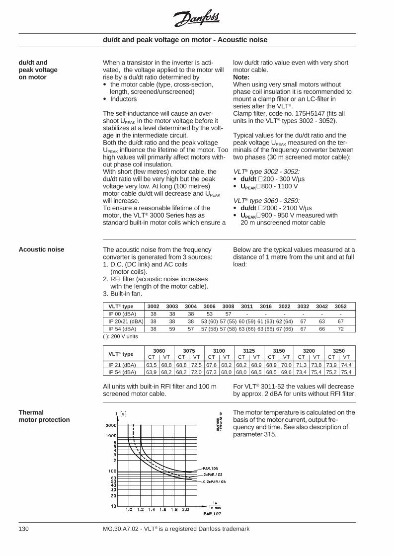
130 MG.30.A7.02 - VLT® is a registered Danfoss trademark
du/dt and peak voltage on motor - Acoustic noise
When a transistor in the inverter is acti-vated, the voltage applied to the motor willrise by a du/dt ratio determined by• the motor cable (type, cross-section, length, screened/unscreened)• Inductors
The self-inductance will cause an over-shoot UPEAK in the motor voltage before itstabilizes at a level determined by the volt-age in the intermediate circuit.Both the du/dt ratio and the peak voltageUPEAK influence the lifetime of the motor. Toohigh values will primarily affect motors with-out phase coil insulation.With short (few metres) motor cable, thedu/dt ratio will be very high but the peakvoltage very low. At long (100 metres)motor cable du/dt will decrease and UPEAK
will increase.To ensure a reasonable lifetime of themotor, the VLT® 3000 Series has asstandard built-in motor coils which ensure a
du/dt andpeak voltageon motor
low du/dt ratio value even with very shortmotor cable.Note:When using very small motors withoutphase coil insulation it is recommended tomount a clamp filter or an LC-filter inseries after the VLT®.Clamp filter, code no. 175H5147 (fits allunits in the VLT® types 3002 - 3052).
Typical values for the du/dt ratio and thepeak voltage UPEAK measured on the ter-minals of the frequency converter betweentwo phases (30 m screened motor cable):
VLT® type 3002 - 3052:• du/dt ∼ 200 - 300 V/µs• UPEAK∼ 800 - 1100 V
VLT® type 3060 - 3250:• du/dt ∼ 2000 - 2100 V/µs• UPEAK∼ 900 - 950 V measured with
20 m unscreened motor cable
The acoustic noise from the frequencyconverter is generated from 3 sources:1. D.C. (DC link) and AC coils
(motor coils).2. RFI filter (acoustic noise increases
with the length of the motor cable).3. Built-in fan.
Acoustic noise Below are the typical values measured at adistance of 1 metre from the unit and at fullload:
All units with built-in RFI filter and 100 mscreened motor cable.
For VLT® 3011-52 the values will decreaseby approx. 2 dBA for units without RFI filter.
Thermalmotor protection
The motor temperature is calculated on thebasis of the motor current, output fre-quency and time. See also description ofparameter 315.
VLT® type 3002 3003 3004 3006 3008 3011 3016 3022 3032 3042 3052IP 00 (dBA) 38 38 38 53 57 - - - - - -IP 20/21 (dBA) 38 38 38 53 (60) 57 (55) 60 (59) 61 (63) 62 (64) 67 63 67IP 54 (dBA) 38 59 57 57 (58) 57 (58) 63 (66) 63 (66) 67 (66) 67 66 72
( ): 200 V units
3060 3075 3100 3125 3150 3200 3250VLT® typeCT VT CT VT CT VT CT VT CT VT CT VT CT VT
IP 21 (dBA) 63,5 68,8 68,8 72,5 67,6 68,2 68,2 68,9 68,9 70,0 71,3 73,8 73,9 74,4IP 54 (dBA) 63,9 68,2 68,2 72,0 67,3 68,0 68,0 68,5 68,5 69,6 73,4 75,4 75,2 75,4
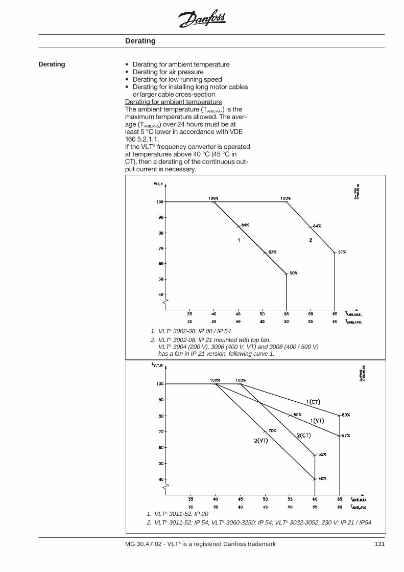
131MG.30.A7.02 - VLT® is a registered Danfoss trademark
Derating
• Derating for ambient temperature• Derating for air pressure• Derating for low running speed• Derating for installing long motor cables
or larger cable cross-sectionDerating for ambient temperatureThe ambient temperature (TAMB,MAX) is themaximum temperature allowed. The aver-age (TAMB,AVG) over 24 hours must be atleast 5 °C lower in accordance with VDE160 5.2.1.1.If the VLT® frequency converter is operatedat temperatures above 40 °C (45 °C inCT), then a derating of the continuous out-put current is necessary.
Derating
1. VLT® 3002-08: IP 00 / IP 542. VLT® 3002-08: IP 21 mounted with top fan.
VLT® 3004 (200 V), 3006 (400 V, VT) and 3008 (400 / 500 V)has a fan in IP 21 version, following curve 1.
1. VLT® 3011-52: IP 202. VLT® 3011-52: IP 54, VLT® 3060-3250: IP 54; VLT® 3032-3052, 230 V: IP 21 / IP54
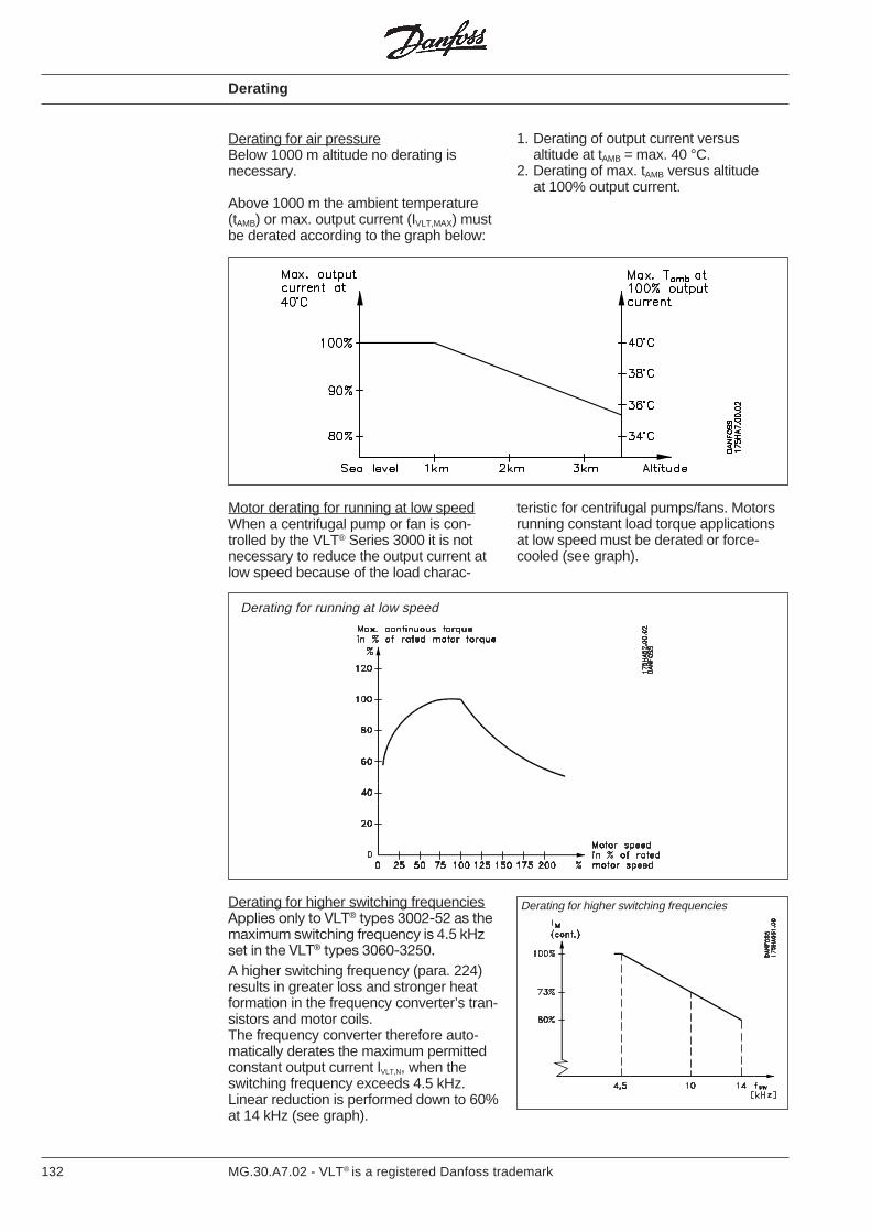
132 MG.30.A7.02 - VLT® is a registered Danfoss trademark
Derating for air pressureBelow 1000 m altitude no derating isnecessary.
Above 1000 m the ambient temperature(tAMB) or max. output current (IVLT,MAX) mustbe derated according to the graph below:
1. Derating of output current versusaltitude at tAMB = max. 40 °C.
2. Derating of max. tAMB versus altitudeat 100% output current.
Derating
teristic for centrifugal pumps/fans. Motorsrunning constant load torque applicationsat low speed must be derated or force-cooled (see graph).
Motor derating for running at low speedWhen a centrifugal pump or fan is con-trolled by the VLT® Series 3000 it is notnecessary to reduce the output current atlow speed because of the load charac-
Derating for running at low speed
Derating for higher switching frequenciesApplies only to VLT® types 3002-52 as themaximum switching frequency is 4.5 kHzset in the VLT® types 3060-3250.A higher switching frequency (para. 224)results in greater loss and stronger heatformation in the frequency converter’s tran-sistors and motor coils.The frequency converter therefore auto-matically derates the maximum permittedconstant output current IVLT,N, when theswitching frequency exceeds 4.5 kHz.Linear reduction is performed down to 60%at 14 kHz (see graph).
Derating for higher switching frequencies
133MG.30.A7.02 - VLT® is a registered Danfoss trademark
Derating for installing long motor cables orlarger cable cross-sectionThe VLT® 3002-3052 is tested with 300 munscreened cable and 150 m screenedcable (for types 3002-3004 this onlyapplies to fSWITCH ≤4.5 kHz. At fSWITCH > 4.5kHz, max. 40 m).
The VLT® 3000 Series is designed to runwith a motor cable of a rated cross-section. Ifa cable with a larger cross-section is to beused it is recommended to reduce the out-put current by 5% for each step thecable cross-section is increased.(Higher cable cross-section givesincreased capacity to earth and thereby in-creased earth current).
Derating - EMC
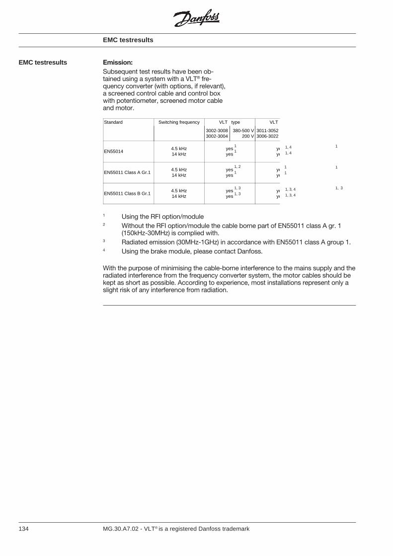
134 MG.30.A7.02 - VLT® is a registered Danfoss trademark
Standard Switching frequency VLT type VLT
3002-30083002-3004
380-500 V200 V
3011-30523006-3022
EN550144.5 kHz14 kHz
yesyes
yeye
EN55011 Class A Gr.14.5 kHz14 kHz
yesyes
yeye
EN55011 Class B Gr.14.5 kHz14 kHz
yesyes
yeye
EMC testresults
EMC testresults Emission:Subsequent test results have been ob-tained using a system with a VLT® fre-quency converter (with options, if relevant),a screened control cable and control boxwith potentiometer, screened motor cableand motor.
With the purpose of minimising the cable-borne interference to the mains supply and theradiated interference from the frequency converter system, the motor cables should bekept as short as possible. According to experience, most installations represent only aslight risk of any interference from radiation.
1 Using the RFI option/module2 Without the RFI option/module the cable borne part of EN55011 class A gr. 1
(150kHz-30MHz) is complied with.3 Radiated emission (30MHz-1GHz) in accordance with EN55011 class A group 1.4 Using the brake module, please contact Danfoss.
11
1
1, 3
1, 3
1
1
1
1
1, 3
1, 2
1, 3, 4
1, 3, 4
1, 4
1, 4
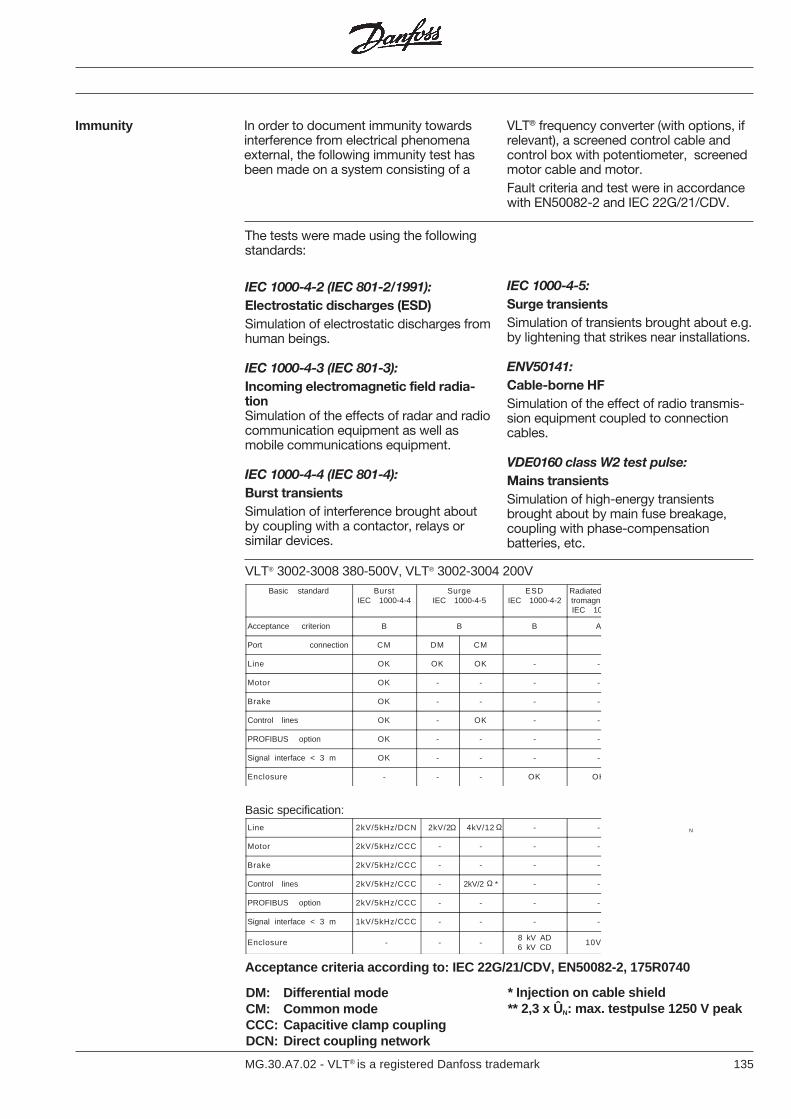
135MG.30.A7.02 - VLT® is a registered Danfoss trademark
Immunity In order to document immunity towardsinterference from electrical phenomenaexternal, the following immunity test hasbeen made on a system consisting of a
VLT® frequency converter (with options, ifrelevant), a screened control cable andcontrol box with potentiometer, screenedmotor cable and motor.Fault criteria and test were in accordancewith EN50082-2 and IEC 22G/21/CDV.
The tests were made using the followingstandards:
IEC 1000-4-2 (IEC 801-2/1991):Electrostatic discharges (ESD)Simulation of electrostatic discharges fromhuman beings.
IEC 1000-4-3 (IEC 801-3):Incoming electromagnetic field radia-tionSimulation of the effects of radar and radiocommunication equipment as well asmobile communications equipment.
IEC 1000-4-4 (IEC 801-4):Burst transientsSimulation of interference brought aboutby coupling with a contactor, relays orsimilar devices.
IEC 1000-4-5:Surge transientsSimulation of transients brought about e.g.by lightening that strikes near installations.
ENV50141:Cable-borne HFSimulation of the effect of radio transmis-sion equipment coupled to connectioncables.
VDE0160 class W2 test pulse:Mains transientsSimulation of high-energy transientsbrought about by main fuse breakage,coupling with phase-compensationbatteries, etc.
VLT® 3002-3008 380-500V, VLT® 3002-3004 200V
Line 2kV/5kHz/DCN 2kV/2 4kV/12 - -
Motor 2kV/5kHz/CCC - - - -
Brake 2kV/5kHz/CCC - - - -
Control lines 2kV/5kHz/CCC - 2kV/2 * - -
PROFIBUS option 2kV/5kHz/CCC - - - -
Signal interface < 3 m 1kV/5kHz/CCC - - - -
Enclosure - - -8 kV AD6 kV CD
10V
Basic specification:
Acceptance criteria according to: IEC 22G/21/CDV, EN50082-2, 175R0740
N
Basic standard BurstIEC 1000-4-4
SurgeIEC 1000-4-5
ESDIEC 1000-4-2
Radiatedtromagn.IEC 10
Acceptance criterion B B B A
Port connection CM DM CM
Line OK OK OK - -
Motor OK - - - -
Brake OK - - - -
Control lines OK - OK - -
PROFIBUS option OK - - - -
Signal interface < 3 m OK - - - -
Enclosure - - - OK OK
Ω Ω
Ω
DM: Differential modeCM: Common modeCCC: Capacitive clamp couplingDCN: Direct coupling network
* Injection on cable shield** 2,3 x ÛN: max. testpulse 1250 V peak
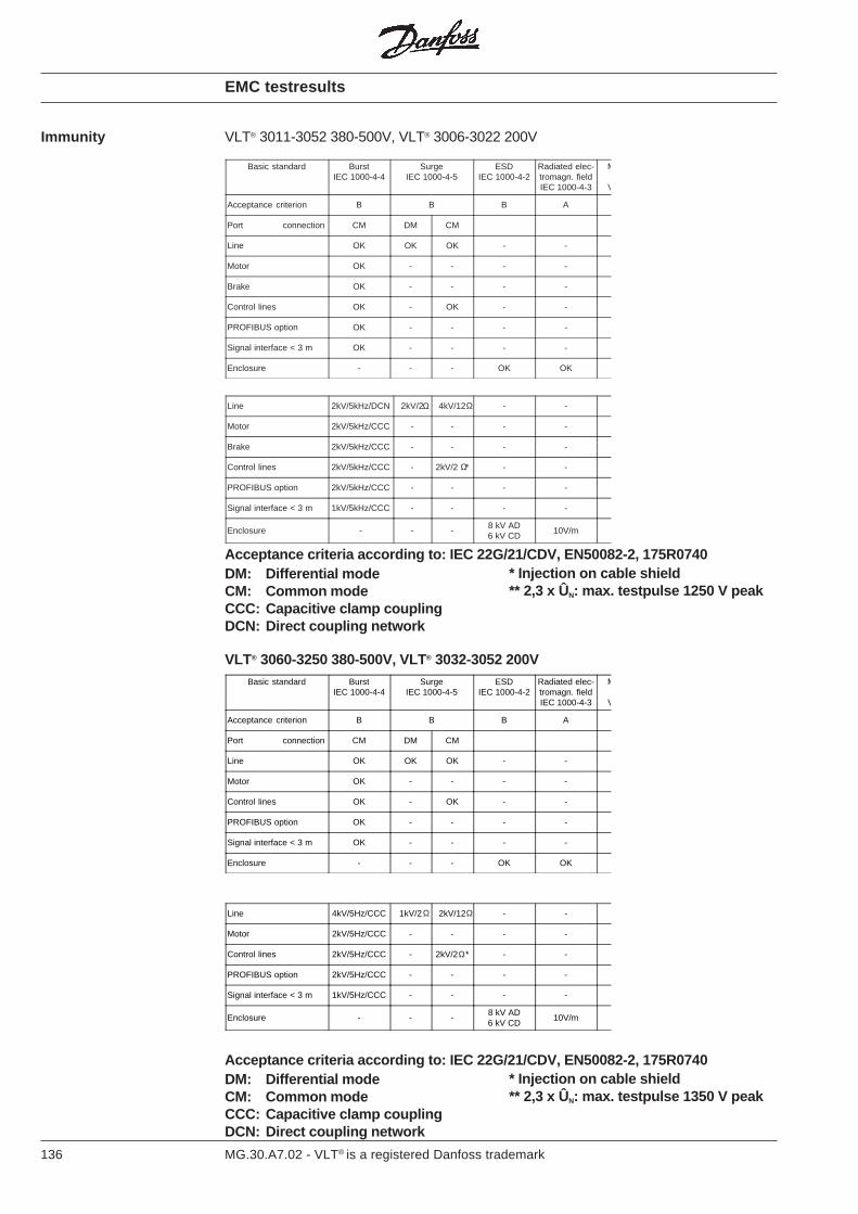
136 MG.30.A7.02 - VLT® is a registered Danfoss trademark
Line 4kV/5Hz/CCC 1kV/2 2kV/12 - - *
Motor 2kV/5Hz/CCC - - - -
Control lines 2kV/5Hz/CCC - 2kV/2 * - -
PROFIBUS option 2kV/5Hz/CCC - - - -
Signal interface < 3 m 1kV/5Hz/CCC - - - -
Enclosure - - -8 kV AD6 kV CD
10V/m
Basic standard BurstIEC 1000-4-4
SurgeIEC 1000-4-5
ESDIEC 1000-4-2
Radiated elec-tromagn. fieldIEC 1000-4-3
M
V
Acceptance criterion B B B A
Port connection CM DM CM
Line OK OK OK - -
Motor OK - - - -
Control lines OK - OK - -
PROFIBUS option OK - - - -
Signal interface < 3 m OK - - - -
Enclosure - - - OK OK
Immunity
EMC testresults
Basic standard BurstIEC 1000-4-4
SurgeIEC 1000-4-5
ESDIEC 1000-4-2
Radiated elec-tromagn. fieldIEC 1000-4-3
M
V
Acceptance criterion B B B A
Port connection CM DM CM
Line OK OK OK - -
Motor OK - - - -
Brake OK - - - -
Control lines OK - OK - -
PROFIBUS option OK - - - -
Signal interface < 3 m OK - - - -
Enclosure - - - OK OK
Line 2kV/5kHz/DCN 2kV/2 4kV/12 - - *
Motor 2kV/5kHz/CCC - - - -
Brake 2kV/5kHz/CCC - - - -
Control lines 2kV/5kHz/CCC - 2kV/2 * - -
PROFIBUS option 2kV/5kHz/CCC - - - -
Signal interface < 3 m 1kV/5kHz/CCC - - - -
Enclosure - - -8 kV AD6 kV CD
10V/m
VLT® 3011-3052 380-500V, VLT® 3006-3022 200V
VLT® 3060-3250 380-500V, VLT® 3032-3052 200V
ΩΩ
Ω
Acceptance criteria according to: IEC 22G/21/CDV, EN50082-2, 175R0740DM: Differential modeCM: Common modeCCC: Capacitive clamp couplingDCN: Direct coupling network
* Injection on cable shield** 2,3 x ÛN: max. testpulse 1250 V peak
Acceptance criteria according to: IEC 22G/21/CDV, EN50082-2, 175R0740DM: Differential modeCM: Common modeCCC: Capacitive clamp couplingDCN: Direct coupling network
* Injection on cable shield** 2,3 x ÛN: max. testpulse 1350 V peak
ΩΩ
Ω
137MG.30.A7.02 - VLT® is a registered Danfoss trademark
The VLT® 3000 Series is tested accordingto a procedure based on the followingstandards:
IEC 68-2-6: Vibration (sinusoidal) - 1970IEC 68-2-34: Random vibration wide
band-general requirementIEC 68-2-35: Random vibration wide
band-reproducibility highIEC 68-2-36: Random vibration wide
band-reproducibility medium
Vibration and shock VLT® 3002-3008 meet the requirementsequal to conditions when mounted close toor directly on heavy production equipment.
VLT® 3011-3052 meet the requirementsequal to conditions when mounted directlyon wall or floor and in panels in factorybuildings.
The VLT® frequency converter has beendesigned to meet the IEC 68-2.3 standard.The VDE 160, 5.2.1.2./7.2.1/ DIN 40040,class E, 40 °C, IP 54, is obtained accordingto IEC 68-2-30.
An occasional light dew is tolerated oninternal insulating surfaces duringoperation.
Air humidity
Vibration and shock - Air humidity
The IP 54 versions can tolerate moremoisture, because less dust and dirt aredeposited on the insulating surfaces, andthe enclosure allows no moisture inside.
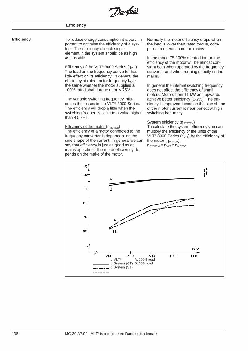
138 MG.30.A7.02 - VLT® is a registered Danfoss trademark
Efficiency
Efficiency
To reduce energy consumption it is very im-portant to optimise the efficiency of a sys-tem. The efficiency of each singleelement in the system should be as highas possible.
Efficiency of the VLT® 3000 Series (ηVLT)The load on the frequency converter haslittle effect on its efficiency. In general theefficiency at rated motor frequency fM,N isthe same whether the motor supplies a100% rated shaft torque or only 75%.
The variable switching frequency influ-ences the losses in the VLT® 3000 Series.The efficiency will drop a little when theswitching frequency is set to a value higherthan 4.5 kHz.
Efficiency of the motor (ηMOTOR)The efficiency of a motor connected to thefrequency converter is dependent on thesine shape of the current. In general we cansay that efficiency is just as good as atmains operation. The motor efficien-cy de-pends on the make of the motor.
Normally the motor efficiency drops whenthe load is lower than rated torque, com-pared to operation on the mains.
In the range 75-100% of rated torque theefficiency of the motor will be almost con-stant both when operated by the frequencyconverter and when running directly on themains.
In general the internal switching frequencydoes not affect the efficiency of smallmotors. Motors from 11 kW and upwardsachieve better efficiency (1-2%). The effi-ciency is improved, because the sine shapeof the motor current is near perfect at highswitching frequency.
System efficiency (ηSYSTEM)To calculate the system efficiency you canmultiply the efficiency of the units of theVLT® 3000 Series (ηVLT) by the efficiency ofthe motor (ηMOTOR):ηSYSTEM = ηVLT x ηMOTOR
: VLT® A: 100% load: System (CT) B: 50% load: System (VT)

139MG.30.A7.02 - VLT® is a registered Danfoss trademark
Harmonic currents compared to the RMSinput current:
The value of I1 is equivalent to the powerfactor.
Power factor
3 x V x I1 x cosϕ1
3 x V x IRMS
I1 x cosϕ1
IRMS
IRMS = I12 + I5
2 + I72 + . . . + In
2
Mains supplyinterference / harmonics
A frequency converter takes up a non-sinusoidal current, which will increase theinput current IRMS. A non-sinusoidal currentcan be transformed by means of a Fourieranalysis and split up into sine wave cur-rents with different frequencies, this meansdifferent harmonic currents IN with 50 Hz asthe basic frequency:
The harmonic currents do not contributedirectly to the power consumption, butincrease the heat losses in the installation(transformer, cables). Therefore, in plantswith a rather high percentage of rectifierload, it is important to maintain harmonicsat a low level to avoid overload of thetransformer and high temperature in the
cables.Some of the harmonics might disturb com-munication equipment connected to thesame transformer or cause resonances inconnection with power-factor correctionequipment.
Due to the above it is important to sup-press these harmonics. The most commonmethod is to mount coils in the mains sup-ply to the frequency converter or in the in-termediate circuit of the frequency con-verter. Coils in the intermediate circuit givethe advantage of a lower voltage dropcompared to the coils in the mains connec-tion.
As standard the VLT® series 3000 has coilsin the intermediate circuit for effective sup-pression of the harmonic currents.
Harmonic currents I1 I5 I7
Hz 50 Hz 250 Hz 350 Hz
Input currentIRMS 1.0I1 0.9I5 0.4I7 0.2I11-49 < 0.1
The voltage distortion of the mains supplydepends on the size of the harmoniccurrents multiplied by the internal imped-ance for the relevant frequency.The total voltage distortion THD is calcu-lated on the individual voltage harmonicsaccording to the following formula:
THD% = U1 + U5+ ..... UN
Furthermore, a high power factor indicatesthat the different harmonic currents are low.
(UN% of U)
=
Power factor =
Mains supply interference / harmonics - Power factor
The power factor is the ratio betweenpower (kW) and total (kVA).Power factor for 3-phased supply
cosϕ1 ≈ 1 ⇒ power factor ≈IRMS
I1
The power factor indicates the frequencyconverter’s load on the supply mains. Thelower the power factor, the higher (IRMS) forthe same kW.
140 MG.30.A7.02 - VLT® is a registered Danfoss trademark
Over-tempThe temperature inside the VLT® frequencyconverter is too high. Possible reasons:the ambient temperature is too high (max.40/45 °C), the VLT® frequency converter’scooling ribs are covered, or the VLT® fre-quency converter's fan is defective.• Reduce the ambient temperature by
increasing the ventilation.Uncover/clean the cooling ribs.Replace the fan.
OverloadThe electronic VLT® protection is active.This means that the motor has consumedmore than 105% of rated VLT® frequencyconverter current for too long.• Reduce the motor load. If this is not
possible the application may require alarger VLT® frequency converter.
Motor tripThe electronic motor protection is active.This means that the current consumed bythe motor at low speed has been too highfor too long.• The motor has been loaded
excessively at low speed.If the load cannot be changed,you must exchange the motor fora bigger one, or provide extra coolingof the existing motor.If so, the electronic motor protectioncan be de-activated in parameter 315.
Fault messages Inverter faultThe VLT® power section is defective.
OvervoltageThe voltage of the VLT® frequency conver-ter’s intermediate circuit (DC-voltage) is toohigh. Possible reasons: line voltage toohigh, transients on the line voltage, or re-generative motor operation.
Note: When the VLT® frequency converteris stopped, repeated transients are charg-ing the intermediate circuit, as it supplies nopower to the motor.• If the fault indication is given when
the speed is reduced, you can increasethe ramp-down time. If this is notpossible, the application may require aVLT® frequency converter with brake.
If the fault indication is given in othersituations, the problem will be due tothe mains supply.
UndervoltageThe voltage of the VLT® frequency conver-ter’s intermediate circuit (DC-voltage) is toolow. Possible reasons: line voltage too lowor defect in the VLT® frequency converter’scharging circuit/rectifier.• Check whether the line voltage is OK.
OvercurrentThe peak current limit of the inverter hasbeen reached. This may be due to a short-circuit in the output of the VLT® frequencyconverter.• Check the motor and the motor cable
for ground failure.
Ground faultGround failure on the VLT® frequency con-verter output. Another reason might be thatthe motor cable is too long.• Consult the data sheets for permitted
cable length.Check the motor and the motor cablefor earth leakage.
Fault messages
141MG.30.A7.02 - VLT® is a registered Danfoss trademark
It is therefore important to take staticelectricity into account when servicing elec-tronic equipment.
When performing field service on DanfossVLT® frequency converters the followingprecautions must be taken:• A portable ESD field service kit
consisting of a wrist strap and aconductive mat must be used.
• The portable ESD field service kit mustbe connected to the same potential asthe VLT® frequency converter.
• Replaced defective control cards mustbe placed in antistatic packing. Thepacking from the new card could beused for this purpose.
Electrostatic discharge(ESD)
Important! Many electronic componentsare sensitive to static electricity. Evenvoltages so low that they cannot be felt,seen or heard can impair components ordamage them completely.
Electronic discharge can, among otherthings, result in the following:
• Drastic reduction in componentoperating life
• Periodic faults - as a rule concurrentlywith varying temperature, vibration or
varying load.• Faults that are difficult to trace and that
cannot be located by testing.
Electrostatic discharge
Use the flow charts The fault location procedure on thefollowing flow charts takes as its startingpoint the main faults affecting the motor,i.e.• Motor runs unevenly• Motor does not run• Motor does not brake
The flow chart layout is generally in aform applicable to all VLT® frequency con-verters, although at certain points it isnecessary to distinguish between some ofthe types.
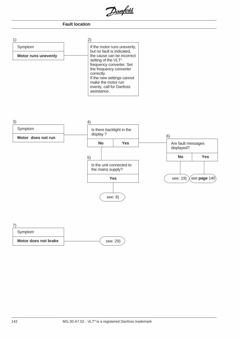
142 MG.30.A7.02 - VLT® is a registered Danfoss trademark
Symptom
Motor runs unevenly
If the motor runs unevenly,but no fault is indicated,the cause can be incorrectsetting of the VLT®
frequency converter. Setthe frequency convertercorrectly.If the new settings cannotmake the motor runevenly, call for Danfossassistance.
1) 2)
Symptom
Motor does not run
3) 4)
6)
5)
see: 8)
see: 19)
Symptom
Motor does not brake
7)
see: 29)
Are fault messagesdisplayed?
No Yes
Is the unit connected tothe mains supply?
Yes
Is there backlight in thedisplay ?
No Yes
Fault location
see page 140
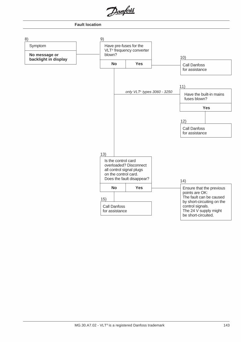
143MG.30.A7.02 - VLT® is a registered Danfoss trademark
Symptom
No message orbacklight in display
Have pre-fuses for theVLT® frequency converterblown?
No Yes
Is the control cardoverloaded? Disconnectall control signal plugson the control card.Does the fault disappear?
No Yes Ensure that the previouspoints are OK:The fault can be causedby short-circuiting on thecontrol signals.The 24 V supply mightbe short-circuited.
8) 9)
13)
10)
11)
14)
only VLT® types 3060 - 3250
Call Danfossfor assistance
12)
Call Danfossfor assistance
15)
Call Danfossfor assistance
Have the built-in mainsfuses blown?
Yes
Fault location
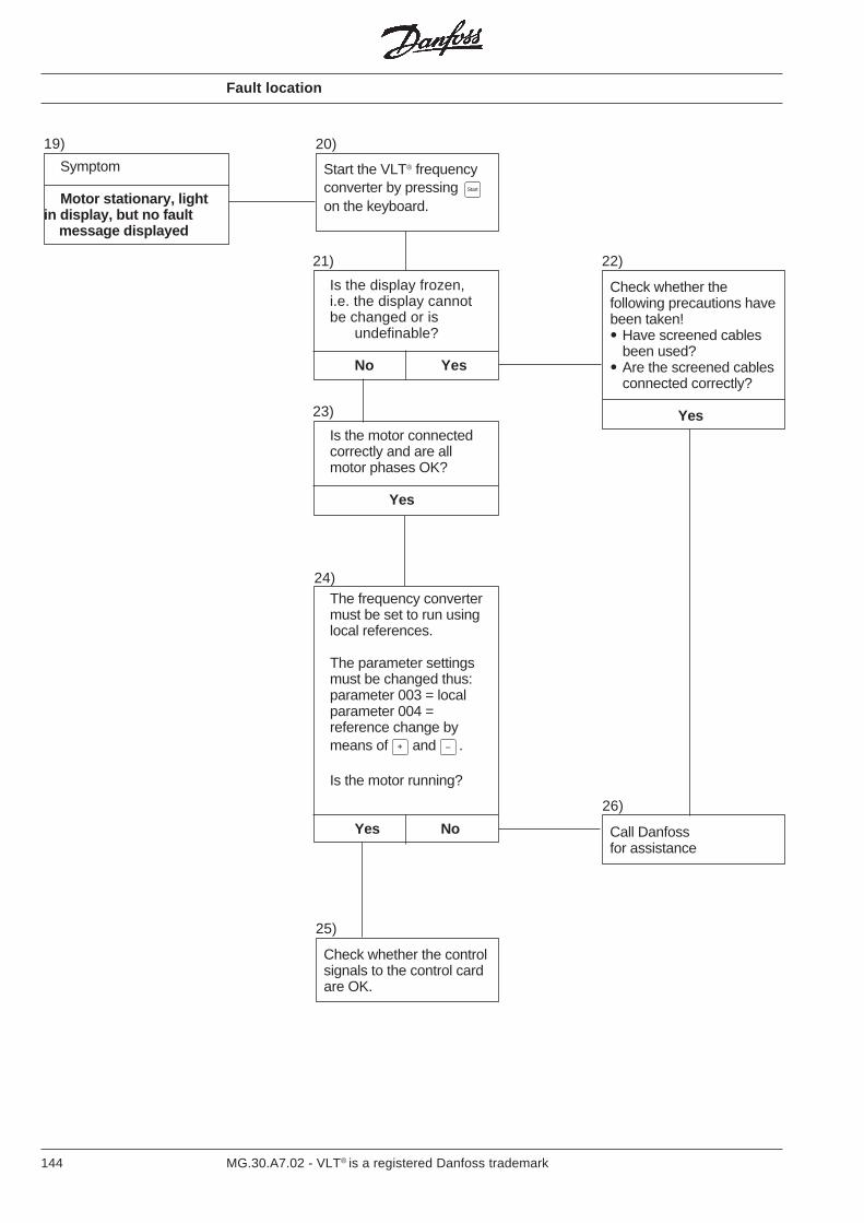
144 MG.30.A7.02 - VLT® is a registered Danfoss trademark
Symptom
Motor stationary, lightin display, but no fault message displayed
Start the VLT® frequencyconverter by pressing Start
on the keyboard.
Is the display frozen,i.e. the display cannotbe changed or is
undefinable?
No Yes
Check whether thefollowing precautions havebeen taken!• Have screened cables
been used?• Are the screened cables
connected correctly?
Yes
19) 20)
21) 22)
Is the motor connectedcorrectly and are allmotor phases OK?
Yes
The frequency convertermust be set to run usinglocal references.
The parameter settingsmust be changed thus:parameter 003 = localparameter 004 =reference change bymeans of + and – .
Is the motor running?
Yes No
Check whether the controlsignals to the control cardare OK.
23)
24)
25)
Call Danfossfor assistance
26)
Fault location
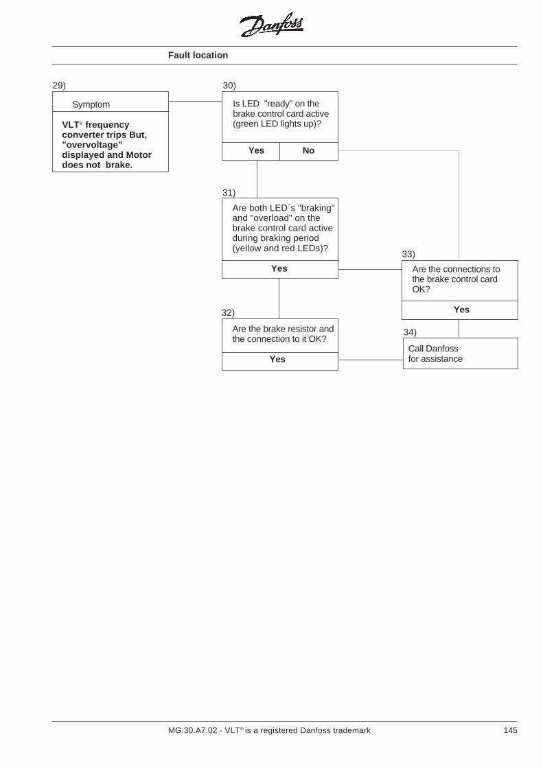
145MG.30.A7.02 - VLT® is a registered Danfoss trademark
Are both LED´s "braking"and "overload" on thebrake control card activeduring braking period(yellow and red LEDs)?
Yes Are the connections tothe brake control cardOK?
Yes
Are the brake resistor andthe connection to it OK?
Yes
29) 30)
31)
32)
33)
Call Danfossfor assistance
34)
Is LED "ready" on thebrake control card active(green LED lights up)?
Yes No
Symptom
VLT® frequencyconverter trips But,"overvoltage"displayed and Motordoes not brake.
Fault location
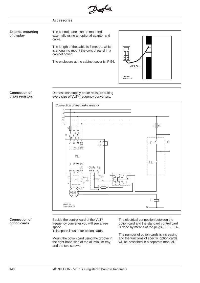
146 MG.30.A7.02 - VLT® is a registered Danfoss trademark
External mountingof display
The control panel can be mountedexternally using an optional adaptor andcable.
The length of the cable is 3 metres, whichis enough to mount the control panel in acabinet cover.
The enclosure at the cabinet cover is IP 54.
Accessories
Danfoss can supply brake resistors suitingevery size of VLT® frequency converters.
Connection ofbrake resistors
Connection of the brake resistor
Connection ofoption cards
Beside the control card of the VLT®
frequency converter you will see a freespace.This space is used for option cards.
Mount the option card using the groove inthe right-hand side of the aluminium tray,and the two screws.
The electrical connection between theoption card and the standard control cardis done by means of the plugs FK1 - FK4.
The number of option cards is increasingand the functions of specific option cardswill be described in a separate manual.
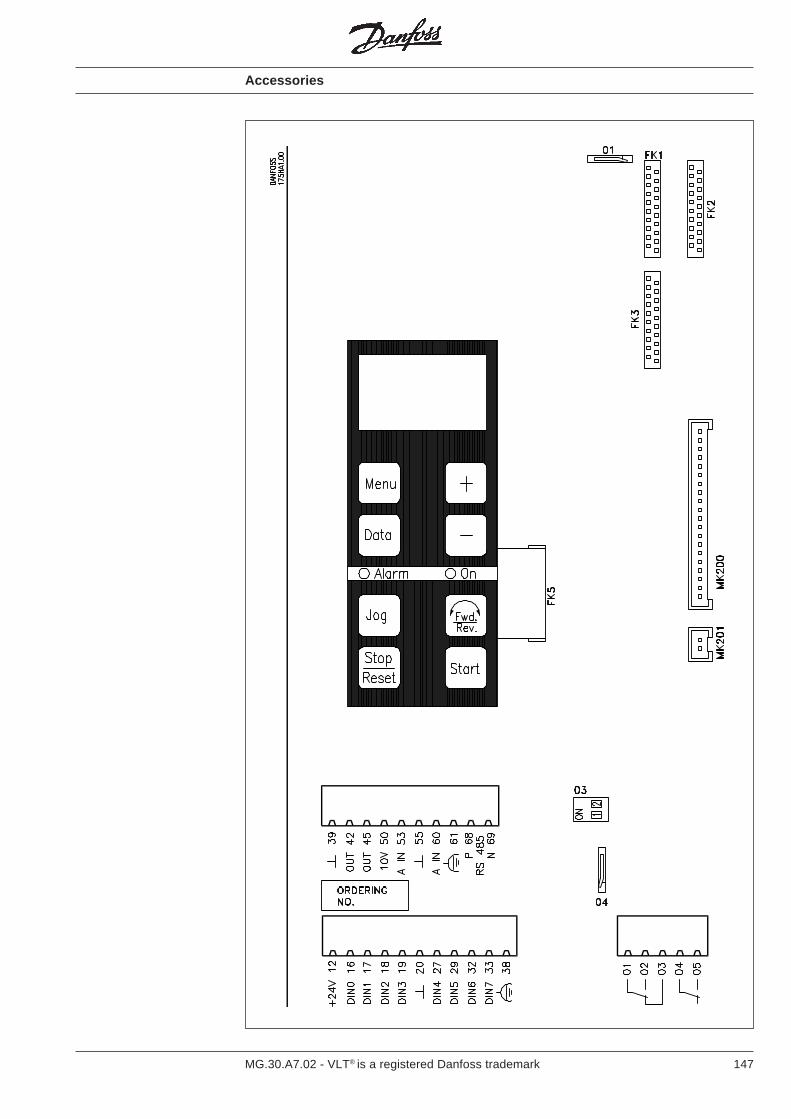
147MG.30.A7.02 - VLT® is a registered Danfoss trademark
Accessories
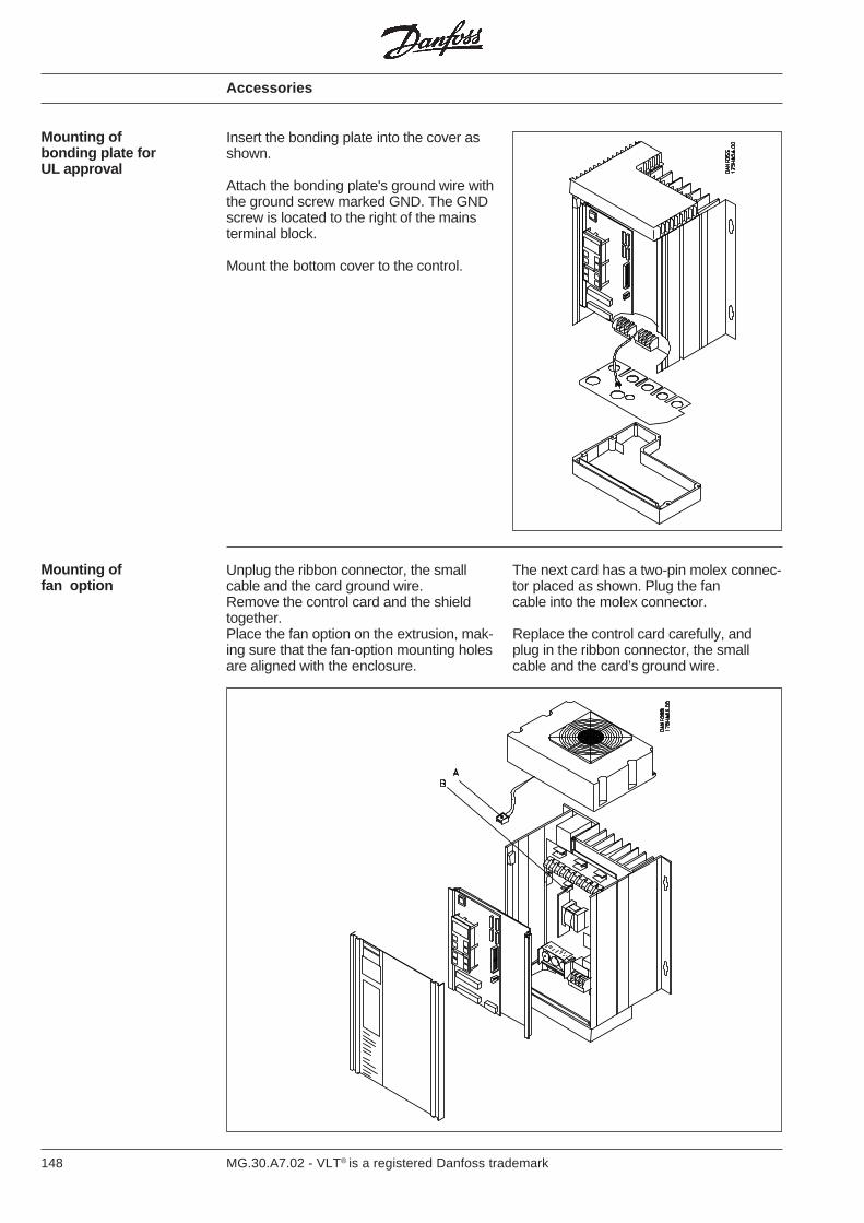
148 MG.30.A7.02 - VLT® is a registered Danfoss trademark
Mounting ofbonding plate forUL approval
Insert the bonding plate into the cover asshown.
Attach the bonding plate's ground wire withthe ground screw marked GND. The GNDscrew is located to the right of the mainsterminal block.
Mount the bottom cover to the control.
Mounting offan option
Unplug the ribbon connector, the smallcable and the card ground wire.Remove the control card and the shieldtogether.Place the fan option on the extrusion, mak-ing sure that the fan-option mounting holesare aligned with the enclosure.
The next card has a two-pin molex connec-tor placed as shown. Plug the fancable into the molex connector.
Replace the control card carefully, andplug in the ribbon connector, the smallcable and the card’s ground wire.
Accessories
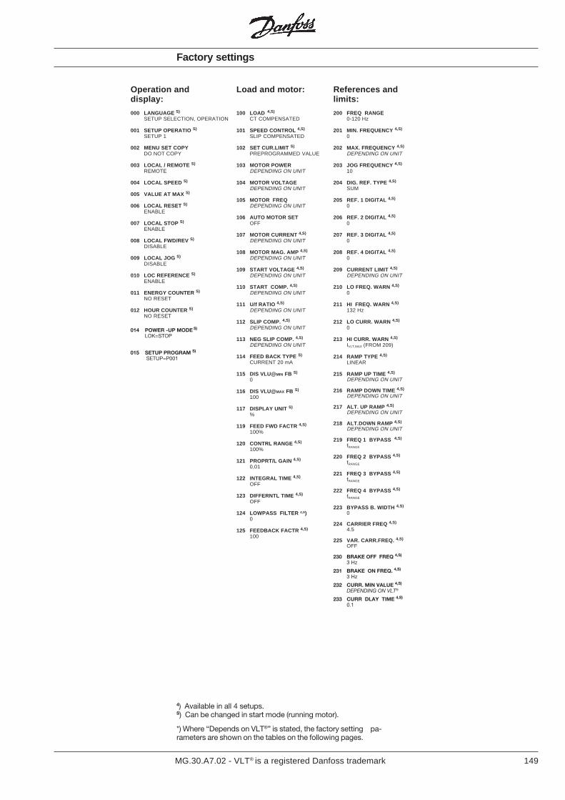
149MG.30.A7.02 - VLT® is a registered Danfoss trademark
Factory settings
Load and motor:
100 LOAD 4,S)
CT COMPENSATED
101 SPEED CONTROL 4,S)
SLIP COMPENSATED
102 SET CUR.LIMIT S)
PREPROGRAMMED VALUE
103 MOTOR POWERDEPENDING ON UNIT
104 MOTOR VOLTAGEDEPENDING ON UNIT
105 MOTOR FREQDEPENDING ON UNIT
106 AUTO MOTOR SETOFF
107 MOTOR CURRENT 4,S)
DEPENDING ON UNIT
108 MOTOR MAG. AMP 4,S)
DEPENDING ON UNIT
109 START VOLTAGE 4,S)
DEPENDING ON UNIT
110 START COMP. 4,S)
DEPENDING ON UNIT
111 U/f RATIO 4,S)
DEPENDING ON UNIT
112 SLIP COMP. 4,S)
DEPENDING ON UNIT
113 NEG SLIP COMP. 4,S)
DEPENDING ON UNIT
114 FEED BACK TYPE S)
CURRENT 20 mA
115 DIS VLU@MIN FB S)
0
116 DIS VLU@MAX FB S)
100
117 DISPLAY UNIT S)
%
119 FEED FWD FACTR 4,S)
100%
120 CONTRL RANGE 4,S)
100%
121 PROPRT/L GAIN 4,S)
0,01
122 INTEGRAL TIME 4,S)
OFF
123 DIFFERNTL TIME 4,S)
OFF
124 LOWPASS FILTER 4,S)0
125 FEEDBACK FACTR 4,S)
100
References andlimits:
200 FREQ RANGE0-120 Hz
201 MIN. FREQUENCY 4,S)
0
202 MAX. FREQUENCY 4,S)
DEPENDING ON UNIT
203 JOG FREQUENCY 4,S)
10
204 DIG. REF. TYPE 4,S)
SUM
205 REF. 1 DIGITAL 4,S)
0
206 REF. 2 DIGITAL 4,S)
0
207 REF. 3 DIGITAL 4,S)
0
208 REF. 4 DIGITAL 4,S)
0
209 CURRENT LIMIT 4,S)
DEPENDING ON UNIT
210 LO FREQ. WARN 4,S)
0
211 HI FREQ. WARN 4,S)
132 Hz
212 LO CURR. WARN 4,S)
0
213 HI CURR. WARN 4,S)
IVLT,MAX (FROM 209)
214 RAMP TYPE 4,S)
LINEAR
215 RAMP UP TIME 4,S)
DEPENDING ON UNIT
216 RAMP DOWN TIME 4,S)
DEPENDING ON UNIT
217 ALT. UP RAMP 4,S)
DEPENDING ON UNIT
218 ALT.DOWN RAMP 4,S)
DEPENDING ON UNIT
219 FREQ 1 BYPASS 4,S)
fRANGE
220 FREQ 2 BYPASS 4,S)
fRANGE
221 FREQ 3 BYPASS 4,S)
fRANGE
222 FREQ 4 BYPASS 4,S)
fRANGE
223 BYPASS B. WIDTH 4,S)
0
224 CARRIER FREQ 4,S)
4.5
225 VAR. CARR.FREQ. 4,S)
OFF
230 BRAKE OFF FREQ 4,S)
3 Hz
231 BRAKE ON FREQ. 4,S)
3 Hz
232 CURR. MIN VALUE 4,S)
DEPENDING ON VLT®
233 CURR DLAY TIME 4,S)
0.1
Operation anddisplay:
000 LANGUAGE S)
SETUP SELECTION, OPERATION
001 SETUP OPERATIO S)
SETUP 1
002 MENU SET COPYDO NOT COPY
003 LOCAL / REMOTE S)
REMOTE
004 LOCAL SPEED S)
005 VALUE AT MAX S)
006 LOCAL RESET S)
ENABLE
007 LOCAL STOP S)
ENABLE
008 LOCAL FWD/REV S)
DISABLE
009 LOCAL JOG S)
DISABLE
010 LOC REFERENCE S)
ENABLE
011 ENERGY COUNTER S)
NO RESET
012 HOUR COUNTER S)
NO RESET
014 POWER -UP MODE S)
LOK=STOP
015 SETUP PROGRAM S)
SETUP=P001
4) Available in all 4 setups.S) Can be changed in start mode (running motor).
*) Where “Depends on VLT®” is stated, the factory setting pa-rameters are shown on the tables on the following pages.
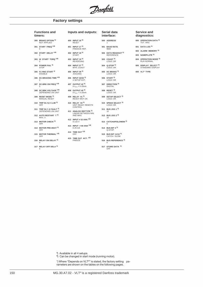
150 MG.30.A7.02 - VLT® is a registered Danfoss trademark
Functions andtimers:
300 BRAKE OPTION S)
NOT APPLIED
301 START FREQ 4,S)
0
302 START DELAY 4,S)
0
303 HI START TORQ 4,S)
0
304 POWER FAIL S)
STOP
305 FLYING START 4)
DISABLE
306 DC-BRAKING TIME 4,S)
0
307 DC-BRK ON FREQ 4,S)
0
308 DC BRK VOLTAGE 4,S)
DEPENDING ON UNIT
309 RESET MODE S)
MANUAL RESET
310 TRIP DLY@ C.LIM S)
OFF
311 TRIP DLY @ FAULT S)
DEPENDING ON UNIT
312 AUTO RESTART T S)
MAX. 5
313 MOTOR CHECK S)
OFF
314 MOTOR PRE-HEAT S)
OFF
315 MOTOR THERMAL 4,S)
OFF
316 RELAY ON DELAY S)
0
317 RELAY OFF DELA S)
0
Inputs and outputs:
400 INPUT 16 S)
RESET
401 INPUT 17 S)
FREEEZE REF.
402 INPUT 18 S)
START
403 INPUT 19 S)
REVERSING
404 INPUT 27 S)
MTR. COAST
405 INPUT 29 S)
JOGGING
406 INPUT 32/33 S)
4 SETUP EXT.
407 OUTPUT 42 S)
0-IMAX = 0-20mA
408 OUTPUT 45 S)
0-fMAX = 0-20mA
409 RELAY 01 S)
READY-MOT.OK
410 RELAY 04 S)
UNIT READY REMOTECONTROL
411 ANALOG REFTYPE S)
LINEAR BETWEEN MIN.AND MAX.
412 INPUT # 53 ANA. 4,S)
0-±10 V
413 INPUT # 60 ANA 4,S)
0-20 mA
414 TIME OUT 4,S)
OFF
415 TIME OUT ACT. 4,S)
FREEZE
Serial datainterface:
500 ADDRESS1
501 BAUD RATE9600
502 DATA READOUT S)
REFERENCE
503 COAST S)
LOGIC OR
504 Q-STOP S)
LOGIC OR
505 DC-BRAKE S)
LOGIC OR
506 START S)
LOGIC OR
507 DIRECTION S)
DIGITAL
508 RESET S)
LOGIC OR
509 SETUP SELECT S)
LOGIC OR
510 SPEED SELECT S)
LOGIC OR
511 BUS JOG 1 S)
10
512 BUS JOG 2 S)
10
513 CATCHUP/SLOWDN S)
0
514 BUS BIT 4 S)
Q-STOP
515 BUS BIT 11/12 S)
CATCH / SLOW
516 BUS REFERENCE S)
0
517 STORE DATA S)
OFF
Service anddiagnostics:
600 OPERATION DATA S)
TOT. HRS
601 DATA LOG S)
602 ALARM MEMORY S)
603 NAMEPLATE S)
604 OPERATION MODE S)
RUN NORMAL
605 DISPLAY SELECT S)
STANDARD DISPLAY
650 VLT® TYPE
4) Available in all 4 setups.S) Can be changed in start mode (running motor).
*) Where “Depends on VLT®” is stated, the factory setting pa-rameters are shown on the tables on the following pages.
Factory settings
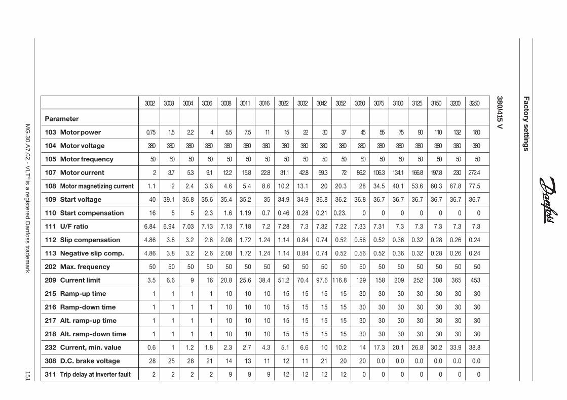
151M
G.30.A
7.02 - VLT
® is a registered D
anfoss trademark
Parameter
103 Motor power 0.75 1.5 2.2 4 5.5 7.5 11 15 22 30 37 45 55 75 90 110 132 160
104 Motor voltage 380 380 380 380 380 380 380 380 380 380 380 380 380 380 380 380 380 380
105 Motor frequency 50 50 50 50 50 50 50 50 50 50 50 50 50 50 50 50 50 50
107 Motor current 2 3.7 5.3 9.1 12.2 15.8 22.8 31.1 42.8 59.3 72 86.2 106.3 134.1 166.8 197.8 230 272.4
108 Motor magnetizing current 1.1 2 2.4 3.6 4.6 5.4 8.6 10.2 13.1 20 20.3 28 34.5 40.1 53.6 60.3 67.8 77.5
109 Start voltage 40 39.1 36.8 35.6 35.4 35.2 35 34.9 34.9 36.8 36.2 36.8 36.7 36.7 36.7 36.7 36.7 36.7
110 Start compensation 16 5 5 2.3 1.6 1.19 0.7 0.46 0.28 0.21 0.23. 0 0 0 0 0 0 0
111 U/F ratio 6.84 6.94 7.03 7.13 7.13 7.18 7.2 7.28 7.3 7.32 7.22 7.33 7.31 7.3 7.3 7.3 7.3 7.3
112 Slip compensation 4.86 3.8 3.2 2.6 2.08 1.72 1.24 1.14 0.84 0.74 0.52 0.56 0.52 0.36 0.32 0.28 0.26 0.24
113 Negative slip comp. 4.86 3.8 3.2 2.6 2.08 1.72 1.24 1.14 0.84 0.74 0.52 0.56 0.52 0.36 0.32 0.28 0.26 0.24
202 Max. frequency 50 50 50 50 50 50 50 50 50 50 50 50 50 50 50 50 50 50
209 Current limit 3.5 6.6 9 16 20.8 25.6 38.4 51.2 70.4 97.6 116.8 129 158 209 252 308 365 453
215 Ramp-up time 1 1 1 1 10 10 10 15 15 15 15 30 30 30 30 30 30 30
216 Ramp-down time 1 1 1 1 10 10 10 15 15 15 15 30 30 30 30 30 30 30
217 Alt. ramp-up time 1 1 1 1 10 10 10 15 15 15 15 30 30 30 30 30 30 30
218 Alt. ramp-down time 1 1 1 1 10 10 10 15 15 15 15 30 30 30 30 30 30 30
232 Current, min. value 0.6 1 1.2 1.8 2.3 2.7 4.3 5.1 6.6 10 10.2 14 17.3 20.1 26.8 30.2 33.9 38.8
308 D.C. brake voltage 28 25 28 21 14 13 11 12 11 21 20 20 0.0 0.0 0.0 0.0 0.0 0.0
311 Trip delay at inverter fault 2 2 2 2 9 9 9 12 12 12 12 0 0 0 0 0 0 0
3002 3003 3004 3006 3008 3011 3016 3022 3032 3042 3052 3060 3075 3100 3125 3150 3200 3250
380/415 V
Factory settings
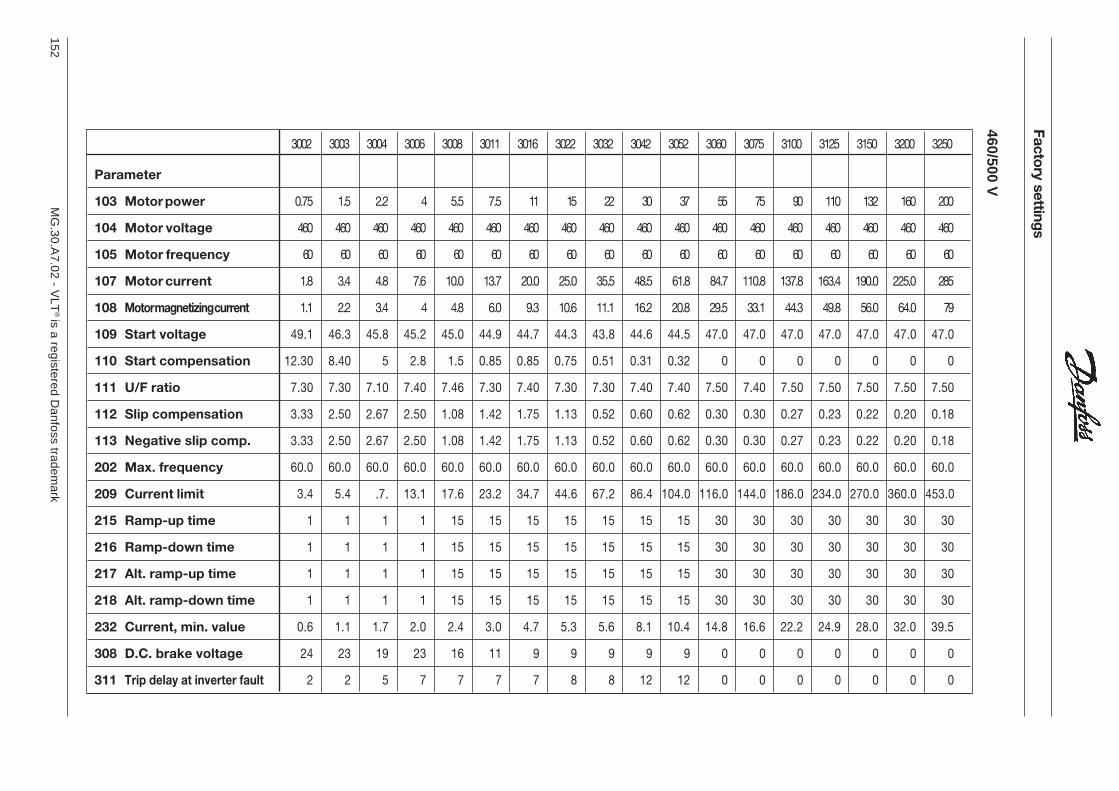
152M
G.30.A
7.02 - VLT
® is a registered D
anfoss trademark
Factory settings
460/500 VParameter
103 Motor power 0.75 1.5 2.2 4 5.5 7.5 11 15 22 30 37 55 75 90 110 132 160 200
104 Motor voltage 460 460 460 460 460 460 460 460 460 460 460 460 460 460 460 460 460 460
105 Motor frequency 60 60 60 60 60 60 60 60 60 60 60 60 60 60 60 60 60 60
107 Motor current 1.8 3.4 4.8 7.6 10.0 13.7 20.0 25.0 35.5 48.5 61.8 84.7 110.8 137.8 163.4 190.0 225.0 285
108 Motor magnetizing current 1.1 2.2 3.4 4 4.8 6.0 9.3 10.6 11.1 16.2 20.8 29.5 33.1 44.3 49.8 56.0 64.0 79
109 Start voltage 49.1 46.3 45.8 45.2 45.0 44.9 44.7 44.3 43.8 44.6 44.5 47.0 47.0 47.0 47.0 47.0 47.0 47.0
110 Start compensation 12.30 8.40 5 2.8 1.5 0.85 0.85 0.75 0.51 0.31 0.32 0 0 0 0 0 0 0
111 U/F ratio 7.30 7.30 7.10 7.40 7.46 7.30 7.40 7.30 7.30 7.40 7.40 7.50 7.40 7.50 7.50 7.50 7.50 7.50
112 Slip compensation 3.33 2.50 2.67 2.50 1.08 1.42 1.75 1.13 0.52 0.60 0.62 0.30 0.30 0.27 0.23 0.22 0.20 0.18
113 Negative slip comp. 3.33 2.50 2.67 2.50 1.08 1.42 1.75 1.13 0.52 0.60 0.62 0.30 0.30 0.27 0.23 0.22 0.20 0.18
202 Max. frequency 60.0 60.0 60.0 60.0 60.0 60.0 60.0 60.0 60.0 60.0 60.0 60.0 60.0 60.0 60.0 60.0 60.0 60.0
209 Current limit 3.4 5.4 .7. 13.1 17.6 23.2 34.7 44.6 67.2 86.4 104.0 116.0 144.0 186.0 234.0 270.0 360.0 453.0
215 Ramp-up time 1 1 1 1 15 15 15 15 15 15 15 30 30 30 30 30 30 30
216 Ramp-down time 1 1 1 1 15 15 15 15 15 15 15 30 30 30 30 30 30 30
217 Alt. ramp-up time 1 1 1 1 15 15 15 15 15 15 15 30 30 30 30 30 30 30
218 Alt. ramp-down time 1 1 1 1 15 15 15 15 15 15 15 30 30 30 30 30 30 30
232 Current, min. value 0.6 1.1 1.7 2.0 2.4 3.0 4.7 5.3 5.6 8.1 10.4 14.8 16.6 22.2 24.9 28.0 32.0 39.5
308 D.C. brake voltage 24 23 19 23 16 11 9 9 9 9 9 0 0 0 0 0 0 0
311 Trip delay at inverter fault 2 2 5 7 7 7 7 8 8 12 12 0 0 0 0 0 0 0
3002 3003 3004 3006 3008 3011 3016 3022 3032 3042 3052 3060 3075 3100 3125 3150 3200 3250
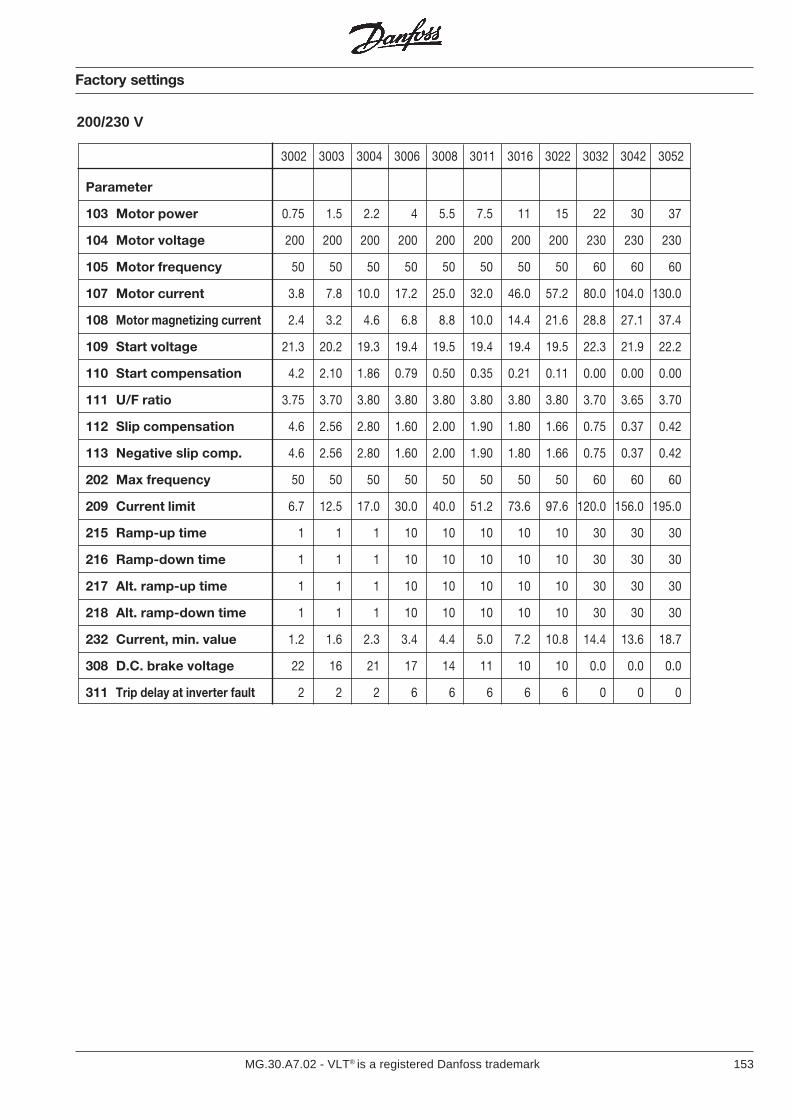
153MG.30.A7.02 - VLT® is a registered Danfoss trademark
200/230 V
3002 3003 3004 3006 3008 3011 3016 3022 3032 3042 3052
Factory settings
Parameter
103 Motor power 0.75 1.5 2.2 4 5.5 7.5 11 15 22 30 37
104 Motor voltage 200 200 200 200 200 200 200 200 230 230 230
105 Motor frequency 50 50 50 50 50 50 50 50 60 60 60
107 Motor current 3.8 7.8 10.0 17.2 25.0 32.0 46.0 57.2 80.0 104.0 130.0
108 Motor magnetizing current 2.4 3.2 4.6 6.8 8.8 10.0 14.4 21.6 28.8 27.1 37.4
109 Start voltage 21.3 20.2 19.3 19.4 19.5 19.4 19.4 19.5 22.3 21.9 22.2
110 Start compensation 4.2 2.10 1.86 0.79 0.50 0.35 0.21 0.11 0.00 0.00 0.00
111 U/F ratio 3.75 3.70 3.80 3.80 3.80 3.80 3.80 3.80 3.70 3.65 3.70
112 Slip compensation 4.6 2.56 2.80 1.60 2.00 1.90 1.80 1.66 0.75 0.37 0.42
113 Negative slip comp. 4.6 2.56 2.80 1.60 2.00 1.90 1.80 1.66 0.75 0.37 0.42
202 Max frequency 50 50 50 50 50 50 50 50 60 60 60
209 Current limit 6.7 12.5 17.0 30.0 40.0 51.2 73.6 97.6 120.0 156.0 195.0
215 Ramp-up time 1 1 1 10 10 10 10 10 30 30 30
216 Ramp-down time 1 1 1 10 10 10 10 10 30 30 30
217 Alt. ramp-up time 1 1 1 10 10 10 10 10 30 30 30
218 Alt. ramp-down time 1 1 1 10 10 10 10 10 30 30 30
232 Current, min. value 1.2 1.6 2.3 3.4 4.4 5.0 7.2 10.8 14.4 13.6 18.7
308 D.C. brake voltage 22 16 21 17 14 11 10 10 0.0 0.0 0.0
311 Trip delay at inverter fault 2 2 2 6 6 6 6 6 0 0 0
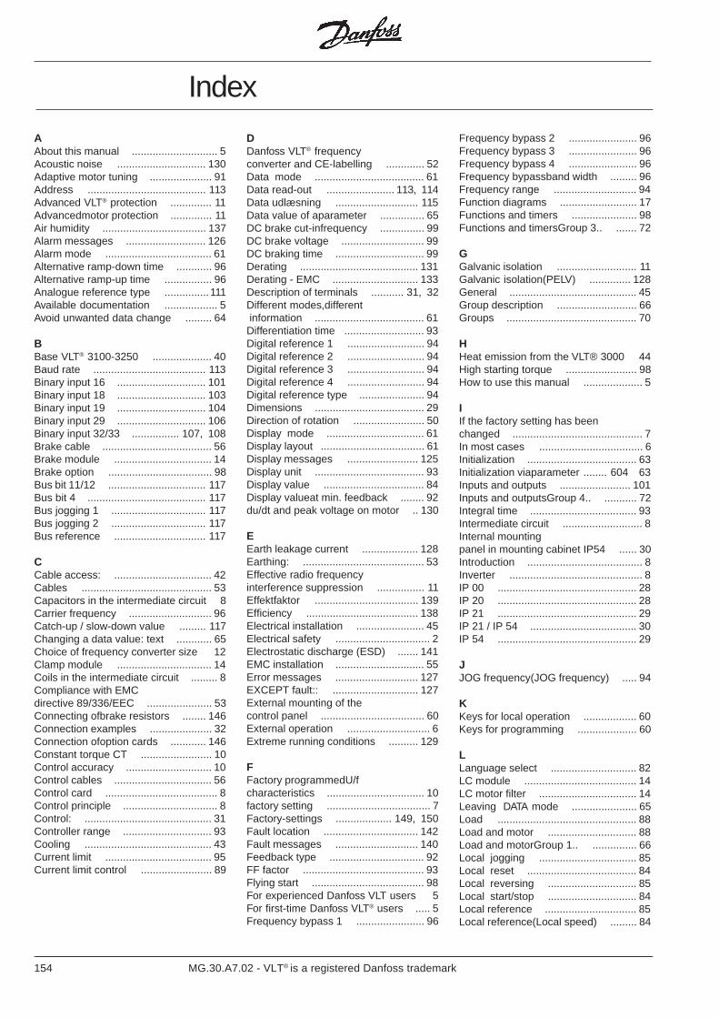
154 MG.30.A7.02 - VLT® is a registered Danfoss trademark
Index
AAbout this manual ............................. 5Acoustic noise .............................. 130Adaptive motor tuning ..................... 91Address ........................................ 113Advanced VLT® protection .............. 11Advancedmotor protection .............. 11Air humidity ................................... 137Alarm messages ........................... 126Alarm mode .................................... 61Alternative ramp-down time ............ 96Alternative ramp-up time ................ 96Analogue reference type ...............111Available documentation .................. 5Avoid unwanted data change ......... 64
BBase VLT® 3100-3250 .................... 40Baud rate ...................................... 113Binary input 16 .............................. 101Binary input 18 .............................. 103Binary input 19 .............................. 104Binary input 29 .............................. 106Binary input 32/33 ................ 107, 108Brake cable ..................................... 56Brake module ................................. 14Brake option ................................... 98Bus bit 11/12 ................................. 117Bus bit 4 ........................................ 117Bus jogging 1 ................................ 117Bus jogging 2 ................................ 117Bus reference ............................... 117
CCable access: ................................. 42Cables ............................................ 53Capacitors in the intermediate circuit 8Carrier frequency ............................ 96Catch-up / slow-down value ......... 117Changing a data value: text ............ 65Choice of frequency converter size 12Clamp module ................................ 14Coils in the intermediate circuit ......... 8Compliance with EMCdirective 89/336/EEC ...................... 53Connecting ofbrake resistors ........ 146Connection examples ..................... 32Connection ofoption cards ............ 146Constant torque CT ........................ 10Control accuracy ............................. 10Control cables ................................. 56Control card ...................................... 8Control principle ................................ 8Control: ........................................... 31Controller range .............................. 93Cooling ........................................... 43Current limit .................................... 95Current limit control ........................ 89
DDanfoss VLT® frequencyconverter and CE-labelling ............. 52Data mode ..................................... 61Data read-out ....................... 113, 114Data udlæsning ............................ 115Data value of aparameter ............... 65DC brake cut-infrequency ............... 99DC brake voltage ............................ 99DC braking time .............................. 99Derating ........................................ 131Derating - EMC ............................. 133Description of terminals ........... 31, 32Different modes,different information ..................................... 61Differentiation time ........................... 93Digital reference 1 .......................... 94Digital reference 2 .......................... 94Digital reference 3 .......................... 94Digital reference 4 .......................... 94Digital reference type ...................... 94Dimensions ..................................... 29Direction of rotation ........................ 50Display mode ................................. 61Display layout ................................... 61Display messages ........................ 125Display unit ..................................... 93Display value .................................. 84Display valueat min. feedback ........ 92du/dt and peak voltage on motor .. 130
EEarth leakage current ................... 128Earthing: ......................................... 53Effective radio frequencyinterference suppression ................ 11Effektfaktor ................................... 139Efficiency ...................................... 138Electrical installation ....................... 45Electrical safety ................................ 2Electrostatic discharge (ESD) ....... 141EMC installation .............................. 55Error messages ............................ 127EXCEPT fault:: ............................. 127External mounting of thecontrol panel ................................... 60External operation ............................ 6Extreme running conditions .......... 129
FFactory programmedU/fcharacteristics ................................. 10factory setting ................................... 7Factory-settings ................... 149, 150Fault location ................................ 142Fault messages ............................ 140Feedback type ................................ 92FF factor ......................................... 93Flying start ...................................... 98For experienced Danfoss VLT users 5For first-time Danfoss VLT® users ..... 5Frequency bypass 1 ....................... 96
Frequency bypass 2 ....................... 96Frequency bypass 3 ....................... 96Frequency bypass 4 ....................... 96Frequency bypassband width ......... 96Frequency range ............................ 94Function diagrams .......................... 17Functions and timers ...................... 98Functions and timersGroup 3.. ....... 72
GGalvanic isolation ........................... 11Galvanic isolation(PELV) .............. 128General ........................................... 45Group description ........................... 66Groups ............................................ 70
HHeat emission from the VLT® 3000 44High starting torque ........................ 98How to use this manual .................... 5
IIf the factory setting has beenchanged ............................................ 7In most cases ................................... 6Initialization ..................................... 63Initialization viaparameter ........ 604 63Inputs and outputs ........................ 101Inputs and outputsGroup 4.. ........... 72Integral time .................................... 93Intermediate circuit ........................... 8Internal mountingpanel in mounting cabinet IP54 ...... 30Introduction ....................................... 8Inverter ............................................. 8IP 00 ............................................... 28IP 20 ............................................... 28IP 21 ............................................... 29IP 21 / IP 54 .................................... 30IP 54 ............................................... 29
JJOG frequency(JOG frequency) ..... 94
KKeys for local operation .................. 60Keys for programming .................... 60
LLanguage select ............................. 82LC module ...................................... 14LC motor filter ................................. 14Leaving DATA mode ...................... 65Load ............................................... 88Load and motor .............................. 88Load and motorGroup 1.. ............... 66Local jogging ................................. 85Local reset ..................................... 84Local reversing .............................. 85Local start/stop .............................. 84Local reference ............................... 85Local reference(Local speed) ......... 84
155MG.30.A7.02 - VLT® is a registered Danfoss trademark
Index
Continued
“LOCK” switch ................................ 64Long motor cables .......................... 11Low disturbance on the mains 1 ........ 1Low pass filter ................................. 93
MMains and motor connection forVLT® types 3002-30 ........................ 46Mains and motor connection forVLT® types 3032-305 ..................... 47Mains failure ................................... 98Mains supply .............................. 8, 23Mains supply interference /harmonics ..................................... 139Manual initialization ........................ 63Max. auto restart time ................... 100Max. frequency ............................... 94Mechanical installation ............ 40, 55Menu mode .................................... 61Menu build-up ................................. 65Min. frequency ................................ 94Motor cable ..................................... 56Motor check .................................. 100Motor coils ........................................ 8Motor connection ............................ 50Motor current .................................. 91Motor frequency .............................. 90Motor power .................................... 90Motor pre-heat .............................. 100Motor thermal protection ............... 100Motor voltage .................................. 90Motormagnetizingcurrent ................ 91Mounting cabinet IP54 .................... 30Mounting of fan option ................. 148Mounting ofbonding plate for ULapproval ........................................ 148
NNegativ slip compensation .............. 92
OOperation and display ..................... 82Operation and displayGroup 0.. ...... 66Operation place .............................. 83Output ............................................... 8
PParallel connection of motors ......... 50Parameter description ............. 82, 83PARAMETER MODE ...................... 61Parameternumbering ...................... 65Personal display select ................. 122Pre-fuses ........................................ 45Product range ................................. 14Programmable control inputsandsignal outputs in 4 ..................... 11Programming keys ............................ 6Proportional gain ............................ 93Protected against mainsdisturbance ..................................... 11
QQuadratic torque VT ....................... 10Quick set-up ..................................... 6
RRadio interference in general ......... 54Ramp type ...................................... 95Ramp-down time ............................ 96Ramp-up time ................................. 96Rectifier .............................................. 8References and limits ..................... 94References and limitsGroup 2.. ...... 71Relay OFF-delay .......................... 100Relay ON-delay ............................ 100Relay output 01 ............................ 110Relay output 04 .............................111Reset ............................................ 116Reset energy counter ..................... 85Reset hour counter ......................... 85Reset messages ........................... 126Reset mode .................................... 99RFI module ..................................... 14RFI module IP21 ............................. 30RFI option ....................................... 14RFI-LC module ............................... 14
SSerial communication ................... 113Serial data interfaceGroup 5.. ......... 73Service and diagnosis, Group 6.. ... 81Signal output 42 ............................ 109Signal output 45 ............................ 110Sizing .............................................. 12Slip compensation .......................... 92Software version: .............................. 1Speed control ................................. 89Start .............................................. 116Start compensation ......................... 92Start delay ...................................... 98Start frequency ............................... 98Start voltage ................................... 91Start-up ............................................. 6Start-up test: ................................. 127Status messages .......................... 123Store data values .......................... 118
TTechnical data ................................. 23Technology ....................................... 9Terminal 53Analogue input voltage 111Terminal 60Analogue input current 111The control panel ............................ 60Thermal motor protection ............. 130These rules concernyour safety ....... 2Time out .......................................... 64Time out function .......................... 112Time out(Time out) ....................... 112Travelling the menu ........................ 65Travelling throughthe menu ............ 65Trip delay at current limit ................ 99Trip delay at inverter fault ............. 100
UU/f ratio ........................................... 92Use the flow charts ....................... 141
VVentilation of VLT® units whenpanel-mounted ................................ 44Vibration and shock ...................... 137VLT type ....................................... 122VLT® 3002-3052 ............................ 40VLT® 3060-3250 ............................ 40VLT® 3100-3250 ............................ 40Voltage Vector Control (VVC) ........... 9
WWarning ............................................ 2Warning current high ...................... 95Warning current low ........................ 95Warning frequency high .................. 95What is CE-labelling? ................ 3, 51Which one to choose? .................... 12