Focus 3 Non-Regen Drive Manual - TecDriver
81
User Guide P/N: FOCUS3N-UG Revision: A1 Date: May 21, 2004 © Control Techniques Drives, Inc. 2004 Focus 3N ¼ to 5HP Single Phase, Uni-Directional Non-Regenerative DC Drive
Transcript of Focus 3 Non-Regen Drive Manual - TecDriver

Page i
P/
Da© Control Techniques
Focus 3N¼ to 5HP Single Phase, Uni-Directional
Non-Regenerative DC Drive
User GuideN: FOCUS3N-UG
Revision: A1te: May 21, 2004
Drives, Inc. 2004

Page ii
General Information
The manufacturer accepts no liability for any consequences resulting frominappropriate, negligent or incorrect installation or adjustment of the optional operatingparameters of the equipment or from mismatching the variable speed drive with themotor.
The contents of this User Guide are believed to be correct at the time of printing. In theinterests of a commitment to a policy of continuous development and improvement, themanufacturer reserves the right to change the specifications of the product or itsperformance, or the contents of the User Guide, without notice.
All rights reserved. No parts of this User Guide may be reproduced or transmitted in anyform or by any means, electrical or mechanical, without permission in writing fromControl Techniques.

Page iii
Customer SupportControl Techniques 359 Lang Boulevard, Building BGrand Island, New York 14072U.S.A. Telephone: (716) 774-1193
It is Control Techniques’ goal to ensure your greatest possible satisfaction with theoperation of our products. We are dedicated to providing fast, friendly, and accurateassistance. That is why we offer you so many ways to get the support you need.Whether it’s by phone, fax or modem, you can access Control Techniques supportinformation 24 hours a day, seven days a week. Our wide range of services include:Fax (716) 774-8327You can FAX questions and comments to Control Techniques Just send a FAX to thenumber listed above.Website and Email www.emersonct.comWebsite: www.emersonct.com
Email: [email protected]
If you have Internet capabilities, you also have access to technical support using ourwebsite. The website includes technical notes, frequently asked questions, releasenotes and other technical documentation. This direct technical support connection letsyou request assistance and exchange software files electronically.Technical Support (716) 774-1193 or (800) 893-2321Email: [email protected]
Control Techniques’ products are backed by a team of professionals who will serviceyour installation. Our technical support center in Grand Island New York is ready to helpyou solve those occasional problems over the telephone. Our technical support centeris available 24 hours a day for emergency service to help speed any problem solving.Also, all hardware replacement parts, if needed, are available through our customerservice organization.When you call, please be prepared to provide the following information:
The type of controller or product you are usingWhat you were doing when the problem occurredHow you tried to solve the problem
Need on-site help? Control Techniques provides service, in most cases, the next day.Just call Control Techniques’ technical support center when on-site service ormaintenance is required. Customer Service (716) 774-1193 or (800) 367-8067Email: [email protected]
Authorized Control Techniques distributors may place orders directly with our CustomerService department. Contact the Customer Service department at this number for thedistributor nearest you.

Page iv
“Warning” indicates a potentially hazardous situation that, ifnot avoided, could result in death or serious injury.
“Caution” indicates a potentially hazardous situation that, ifnot avoided, may result in minor or moderate injury.
“Caution” used without the safety alert symbol indicates apotentially hazardous situation that, if not avoided, may result in propertydamage.

Page v
Safety Considerations
Safety PrecautionsThis product is intended for professional incorporation into a complete system. Ifyou install the product incorrectly, it may present a safety hazard. The productand system may use high voltages and currents, carry a high level of storedelectrical energy, or are used to control mechanical equipment that can causeinjury.
You should give close attention to the electrical installation and system design toavoid hazards either in normal operation or in the event of equipmentmalfunction. System design, installation, commissioning and maintenance mustbe carried out by personnel who have the necessary training and experience.Read and follow this safety information and instruction manual carefully.
EnclosureThis product is intended to be mounted in an enclosure that prevents accessexcept by trained and authorized personnel and prevents the ingress ofcontamination. This product is designed for use in an environment classified aspollution degree 2 in accordance with IEC664-1. This means that only dry, non-conducting contamination is acceptable.
Setup, Commissioning and MaintenanceIt is essential that you give careful consideration to changes to drive settings.Depending on the application, a change could have an impact on safety. Youmust take appropriate precautions against inadvertent changes or tampering.Restoring default parameters in certain applications may cause unpredictable orhazardous operation.
Safety of MachineryWithin the European Union all machinery in which this product is used mustcomply with Directive 89/392/EEC, Safety of Machinery.
The product has been designed and tested to a high standard, and failures arevery unlikely. However the level of integrity offered by the product’s controlfunction – for example stop/ start, forward/reverse and maximum speed – is notsufficient for use in safety-critical applications without additional independentchannels of protection. All applications where malfunction could cause injury orloss of life must be subject to a risk assessment, and further protection must beprovided where needed.

Page vi
General warningFailure to follow safe installation guidelines can cause death or serious injury. Thevoltages used in this unit can cause severe electric shock and/or burns, and could belethal. Extreme care is necessary at all times when working with or adjacent to thisequipment. The installation must comply with all relevant safety legislation in the countryof use.
AC supply isolation deviceThe AC supply must be removed from the drive using an approved isolation device ordisconnect before any servicing work is performed, other than adjustments to thesettings or parameters specified in the manual. The drive contains capacitors, whichremain charged to a potentially lethal voltage after the supply has been removed.
Grounding (Earthing, equipotential bonding)The drive must be grounded by a conductor sufficient to carry all possible fault currentin the event of a fault. The ground connections shown in the manual must be followed.
FusesFuses or over-current protection must be provided at the input in accordance with theinstructions in the manual.
Isolation of control circuitsThe installer must ensure that the external control circuits are isolated from humancontact by at least one layer of insulation rated for use at the applied AC supply voltage.

Page vii

Page 2
Table of Contents
Topic Page
Introduction 4Motor Compatibility 5Eddy Current Clutch Control 6Basic Control Modes/Feedback 7 Armature Voltage Feedback 7 Speed or Tach Feedback 7Quick Stops 7Receiving, Inspection, Storing 8Performance Features 9Nameplate Information 10Nameplate Location 10Catalog Number Definition 10
Specifications Ratings Table 11 Performance Specifications 12 Operating Conditions 12Internal Adjustments (Potentiometer) 12Customer Selections (Jumpers) 12Operator Functions 13Control Circuit Specifications 13Options 13Dimensions 14-15Option Kits & Descriptions 16-20
Customer Connections & Start-Up
Start-Up Guidelines 21Incoming Power Requirements 22Grounding 22Motor Wiring 22-23
When viewing this document electronically, the Table of Content items are active andwill direct you to that topic by clicking on that item.

Page 3
Table of Contents
Topic Page
Power Wiring 24-25
Control Wiring 26-33Speed Pot Wiring 33
Customer SelectionsJumper Programming 34-38
Current Ranges 35Current/Torque Control 35
LED Status Indicators 39Potentiometer Adjustments 40-46 Basic Adjustments 41-42
Tuning Adjustments 43-44
Interconnect DrawingsFunctional Block Diagram 47Non-Regen Circuit Overview 48
Start-up Guide Worksheet 49-51
Initial Start-Up & Basic Test Setups 52Installation of Option Kits 52Motor Test 53-55
Trouble Shooting Guide 56-59Light Bulb Test 60-61
Retrofitting Focus 3 to Focus 2 Applications 62-64
Application Notes 65Tachometer Follower Application 66-67Drive Isolation 68-72
Spare Parts 73
When viewing this document electronically, the Table of Content items are active andwill direct you to that topic by clicking on that item.

Page
IntroductionThis is the User’s Guide for Focus 3N (Non-regenerative) series of DC Drives. The Focus
3 is a 3rd generation product of the long-standing Focus series. The Focus 1 was introducedback in 1980 and the Focus 2 later in 1982. The Focus 2 was retired when the Focus 3 wasintroduced as it took advantage of many technological advances in power electronics. TheFocus 3 Non-regen is a single-phase, uni-directional analog drive for DC motors with powerranges from ¼ to 5HP.
Your Focus 3N is a general purpose non-regenerative DC motor speed controller that ispowered from either 115Vac or 230Vac single phase power. A non-regenerative (singlequadrant) drive is one that can provide motoring torque for acceleration and to overcome ratedloads. There are a great many applications where non-regenerative drives provide the mosteconomical solution. A non-regenerative drive however cannot slow down a motor faster thanthe motors normal coasting rate (unless a Dynamic Braking stop is commanded) nor can it stopoverhauling load situations. For more demanding applications, a sister drive- the Focus 3Regen (regenerative model), offers full four quadrant operation for bi-directional motor controland controlled deceleration as well as opposition to overhauling loads.
Both drives incorporate many features that are standard on high performance systemdrives, such as dynamic stability and built-in signal follower adjustments. Focus 3 drives comein two basic model variations- with and without enclosure.
Chassis Model
The model without an enclosure is denoted as a chassis model.The chassis model is intended for mounting within a Usersupplied cabinet and where the User intends to provide remoteStart/Stop and Speed control signals.
Enclosed Model
The Enclosed version comes to you already in a NEMA 4/12enclosure that would allow the User to mount the Focus on a wallor machine surface. The Enclosed version has Start/Stop and theSpeed Control adjustment on the front cover for convenientoperation.
For a complete overview of the Focus 3 productline and available options, visit our website at:www.emersonct.com or click the link below:
Focus 3 Catalog Section
4

Page 5
Motor CompatibilityThe Focus 3 was designed to run standard 90 Vdc or 180 Vdc Shunt Wound or PermanentMagnet DC motors in one direction. The Focus 3 can run motors with other characteristics(such as Universal motors) but one must review those requirements to insure compatibility.Universal motors have commutator brushes but typically plug into the AC power line. Universalmotors are often used in tools such as Drills, Saws, Shop VAC’s, Routers, etc and typicallycannot be run in reverse.
Shunt Wound Motors that are controlled by single phase DC drives typically have 4 powerwires. Two of these are the Armature leads typically designated A1 & A2 or A+ & A-. Theother two power wires are the shunt field leads and typically designated F1 & F2 or F+ & F-.The Focus 3 can supply up to 1 Amp for shunt field excitation (field current requirementsbeyond 1A may damage field rectifier diodes). If your motor does not have Field Currentinformation on the nameplate, you can determine compatibility by measuring your motors Fieldresistance using a calibrated ohmmeter.
Motors with:
90v Armatures typically require 100 Vdc for field excitation. In these cases, the Focus3 requires 120vac input power and must be internally set for this input level. The motorField resistance should not be less than 100 ohms when cold.
180v Armatures typically require 200 Vdc for field excitation. In these cases, the Focus3 requires 240vac input power and must be internally set for this input level. The motorField resistance should not be less than 200ohms when cold.
240v Armatures typically require 150 Vdc for field excitation. In these cases, the Focus3 requires 240vac input power and must be internally set for this input level. The motorfield resistance should not be less than 150 ohms when cold and will require a seriesresistor to drop the additional field supply voltage. Consult Control Techniques TechnicalSupport for additional information.
Motors with:
Permanent Magnet Motors typically have only 2 power wires. These are the Armatureleads and typically designated A1 and A2 or A+ and A-.

Page 6
Eddy Current Clutch Controls
Focus 3 Non-Regenerative Drives have been used to replace many of our old EddyCurrent Clutch Drive units. To regulate speed the clutch output shaft typically employeda tachometer (typically AC but DC could also be used)
A Replacement Solutionfor 1235 / 367 Eddy Current Controllers
F3N2C-EC
The Eddy Current controls were a very popular means of providing variable speedcontrol of a machine back in the 1970’s. A simple 10-amp eddy current controller couldactually control the speed/torque of a 900 HP motor. The F3N2C-EC can provide coilcurrent up to 10 amps dc in 5 ranges starting at 2.7amps by setting a programmingjumper. This current level can be “fine tuned” to the exact coil current of the clutch beingcontrolled. For more specific information, refer to CTAN213 via the Internet at ourwebsite: www.emersonct.com or click the link below:
CTAN213
F3N2C-EC
WER EddyCurrent 367Controller
Emerson EddyCurrent 1235
Controller
Control TechniquesFocus Eddy Current
Controller

Page 7
Speed Control
Armature Voltage Feedback
The Focus 3 can vary the speed of the motors mentioned above as a function of theSpeed potentiometer setting (or external speed command signal) by simply varying theoutput Armature voltage (field excitation if used typically remains constant). A greatmany motor applications do not require ultra precise speed control. Because of this, theFocus 3 is factory set for Armature Voltage Feedback. Armature Voltage Feedback (orsimply Armature Feedback) does not require any special motor mounted speedfeedback device and is therefore inherently quite reliable and is capable of providing upto 1% speed regulation.
Speed Feedback- Tachometer
Should more precise speed control be required, the Focus 3 can accommodate thosemotors equipped with DC Tachometers (AC tachometers require an option kit). DCtachometers output a linear voltage proportional to their RPM and can provide the Focus3 with exact motor speed feedback information. With good DC tachometers up to 0.5%speed accuracy can be achieved. AC tach’s are not as accurate as DC tach’s but DCtach’s require brush maintenance whereas the AC tach has no brushes.
Tach failure will typically result in motor speed runaway. One who designssystems with Speed Feedback devices such as DC tachometers should be
cognizant of this fault condition and must take machine design precautionsshould this event occur.
We would recommend that all DC Drives be initially run using Armature VoltageFeedback to verify operation even if Tach Feedback is the ultimate goal.
Quick Stops
A non-regenerative drive cannot stop a motor faster than the motors normal coastingrate unless a Dynamic Braking resistor is employed. The DB option provides a ratherquick stopping action and provides motor turning resistance when the drive is not in theRUN condition. The Focus 3N can be outfitted with a Dynamic Braking resistor shouldthis requirement be desired.
Note: DB Resistors require Contactor Option - See Options
Power Outages
Shunt Wound MotorsShould a power outage occur, the drive would turn off and the motor would coast to rest.If a Dynamic Braking resistor were employed there would typically be enough decayingfield strength to enable some faster stopping action.
Permanent Magnet MotorsShould a power outage occur, the drive would turn off and the motor would coast to rest.If a Dynamic Braking resistor were employed, full Dynamic Braking force would beexerted because the field is maintained by the motors internal permanent magnets.Therefore, there would be motor turning resistance during power outages as well.

Page 8
General Information
Introduction
The purpose of this manual is to provide the user with the information needed toinstall, start-up, and maintain the Focus 3 drive. This instruction manual should be readin its entirety, paying special attention to the warning and caution notices, beforeinstallation and before performing any start-up or drive maintenance.
Receiving
The user is responsible for inspecting the equipment thoroughly before acceptingthe shipment from the freight company. Check the items received against the purchaseorder. If any items are obviously damaged, do not accept delivery until the damage hasbeen noted on the freight paperwork.
Inspection
Before installation and start-up of the drive, inspect the unit for mechanical integrity(i.e. loose parts, wires, etc). If physical damage was sustained during shipment, leavethe shipping container intact and notify the freight agent. After unpacking, check thedrive nameplate catalog number against the purchase order. See page 10 fornameplate location.
Storing
Store the drive in its shipping container prior to installation. If the drive isn’t usedfor a period of time, store according to the following instructions in order to maintainwarranty coverage:
Clean, dry locationAmbient Temperature Range: -400C to 700C
Humidity: 95%, Non-condensing
Improper procedures can resqualified electrical maintenancstandard safety precautions shapparatus.
ult in personal injury or equipment damage. Onlye technicians familiar with electronic drives and theirould be permitted to install, start-up, or maintain this

Page 9
PERFORMANCE FEATURES
• Solid State Full Wave Power Bridge -Uses generously rated power semiconductors for Maximum reliability and long life.• Inner Current Loop Regulator - Inherent high bandwidth capability for fast response.
• Semiconductor Fusing - Both AC lines fused for maximum protection in case of shortcircuit.
• AC Line Filter and Transient Voltage Suppressor Network - Eliminates interactionbetween other drives or AC equipment.
• Current Limit Ranges - Selectable current limit ranges to match the drive to the motorbeing used. Provides smooth acceleration of high inertia loads.
• Speed Regulator - 1 % accuracy armature voltage feedback with IR compensation or 0.5 %accuracy with DC tachometer feedback. Regulation accuracy may be affected by thetachometer selected.
• Current (Torque) Regulator -2% accuracy armature current regulator allows the user to control motor torque instead ofspeed.
• Circuit Board Indicators - Light emitting diodes (LEDs) on the control board indicate whenthe drive is in Run Mode or the Current Limit is enabled.
• Remote Current Limit - Available by the simple addition of a potentiometer.• Current Signal Follower lnput* - Allows the motor speed to be controlled by a current
signal from a commercially available transducer. The signal may be one of the following: 1 -5mA or 4-20mA• Voltage Signal Follower lnput* - Allows the motor speed to be controlled by a voltage
signal from a DC tachometer generator or a process voltage signal. It accepts an input witha range of 0-200 Vdc.
• Auto/Manual Operation - Standard circuitry allows the drive to be controlled by theoperator speed potentiometer or by the current/voltage signal inputs.
• UL/cUL - All Focus 3 Drives are UL/cUL listed.
*Use voltage or current input
• The current/voltage signal must be ungrounded and isolated from the AC powersource and other controls which use the signal. If the signal is not isolated, anisolator (such as #F3NSBD) must be used or drive damage will occur.
• One cannot make a connection to ground or a grounded device to any terminal orconnection point to the Focus 3 Non-Regenerative Drive without causing drivedamage. Such failures unfortunately cannot be warranted.
• See Ways of Achieving Isolation on page 69 of this manual

Page 10
The Focus 3 comes in two basic model variations- with and without enclosure.
Chassis ModelThe model without an enclosure is denoted as a chassis model. The chassis model isintended for mounting within a User supplied cabinet and where the User intends toprovide remote Start/Stop and Speed control signals. Enclosed ModelThe Enclosed version comes to you already in a NEMA 4/12 enclosure that would allowthe User to mount the Focus on a wall or machine surface. The Enclosed version hasStart/Stop and the Speed Control adjustment on the front cover for convenient operation.
Nameplate Information
Always record the drive Model Number, Part Number and Serial Number for futurewarranty situations and spare parts. A good location to record these is on the Start-upGuide Worksheet on page #49.
Enclosed Unit
Chassis Unit
Model # Part #
Serial #
Model Number Definition
F3 N 2 C
EnclosureChassis (C)Enclosed (E)
Max HP Rating @240vac2 HP (2)5 HP (5)
Non-Regen (N)Regen (R)
Drive FamilyFocus 3 (F3)
Page 11
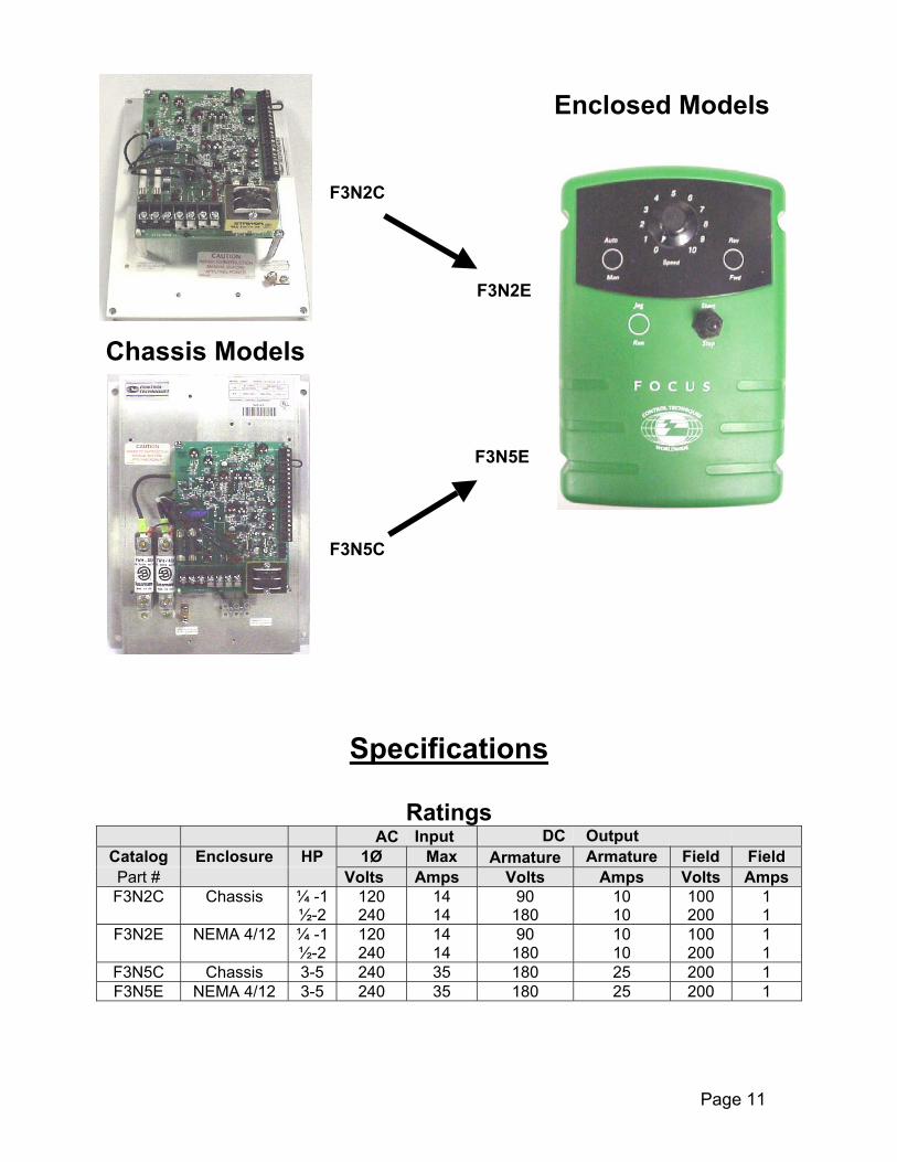
Specifications
RatingsAC Input DC Output
Catalog Enclosure HP 1Ø Max Armature Armature Field FieldPart # Volts Amps Volts Amps Volts AmpsF3N2C Chassis ¼ -1
½-2120240
1414
90180
1010
100200
11
F3N2E NEMA 4/12 ¼ -1½-2
120240
1414
90180
1010
100200
11
F3N5C Chassis 3-5 240 35 180 25 200 1F3N5E NEMA 4/12 3-5 240 35 180 25 200 1
F3N5C
F3N2C
F3N2E
F3N5E
Chassis Models
Enclosed Models

Page 12
PERFORMANCE SPECIFICATIONS
Service Factor 1.0Speed Regulation (95% Load Change): Armature Voltage 1% of Max. Speed with IR Compensation All other variables
(voltage regulated) 15% of Base Speed Tachometer Feedback (DC) 0. 5% of Base SpeedSpeed Range: 30:1Efficiency: Control Only 98% Drive System (motor and control) 86% typically
DRIVE OPERATING CONDITIONS
Altitude (without derating) 3300Ft.Ambient Temperature: Chassis Models 0-550C ( 130° F ) Enclosed (NEMA 4/12) 0-400C ( 104° F )
INTERNAL ADJUSTMENTS (POTENTIOMETERS)
Potentiometer Function RangeMaximum Speed 80-120% of Rated SpeedMinimum Speed 0-30% of Maximum SpeedIR Compensation 0-20% of Rated VoltageCurrent Limit 0-150% of Selected RangeAcceleration Time 0.3-20 seconds (linear)Deceleration Time 0.3-20 seconds (linear)Jog Speed 0-30% of Full Speed commandSpeed Loop Offset AdjustableVelocity Loop Stability AdjustableCurrent Loop Stability AdjustableCurrent Signal Follower Gain AdjustableVelocity Signal Follower Gain AdjustableSignal Follower Zero Bias Adjustable
CUSTOMER SELECTIONS (JUMPERS)
Function Range Input Voltage 120/240Vac Control Mode Speed / Torque Current Feedback range High / Medium / Low / Xlow Current Limit Pot Selector Local / Remote Armature Voltage level 90 Vdc/180 Vdc Optional “M” Contactor Yes/No Tachometer Feedback High/Low Speed Feedback Selector Armature / Tachometer Line Frequency 50/ 60Hz

Page 13
OPERATOR FUNCTIONSChassis Enclosed
Speed Adjustment (Speed Pot) Standard StandardStart/Stop Customer Supplied StandardAuto/Manual Optional OptionalRun/Jog Optional Optional
CONTROL CIRCUIT SPECIFICATIONS
Logic Control Power 24 Vdc
Speed Potentiometer 5000 ohms
Input Signal Requirement 10 Vdc @ 0.5mA
Control Circuit Isolation Optional with non-regen F3N modelsStandard with regen F3R models
Current Signal Follower 1-5mA or 4 - 20mA
Voltage Signal Follower 10 – 200 Vdc (at Maximum Speed)
FOCUS 3 OPTIONS
CATALOGNUMBER DESCRIPTION
F3SE Enclosure Small (2HP), NEMA 4/12F3LE Kits Large (5HP), NEMA 4/12
F3M112 “M” ¼ - 1HP @ 120VF3M224 Contactor ½ - 2HP @ 240VF3M524 Kits 3 - 5HP @ 240VF3DB224 ½ HP @ 120V, 2HP @ 240VF3DB1524 ¼ - 1/3 HP @ 120V, I .5HP @ 240V
F3DB124 Dynamic ¾ -1HP @ 240VF3DB0524 Braking ½ HP @ 240VF3DB112 Kits ¾ -1HP @ 120VF3DB324 3HP @ 240VF3DB524 5HP @ 240V
F3TS Toggle Switch, NEMA 4 /12F3NSBD Signal Isolation Board2450-9024 Remote Percent Speed Meter Kit2450-9021 Remote RPM Speed Meter Kit2950-9066 Remote OperatorStation ( 3 Function )2950-9068 Remote OperatorStation ( 5 Function )6160-9001 Ten-Turn Precision Potentiometer

Page 14
Focus 3 Chassis DimensionsChassisSuitable for mounting in a user’s enclosure where internal temperatures will not exceed550C.
F3N2C
F3N5C
MOUNTINGNON-REGEN
REGEN &
SMALL
T1
0.168" (4 PLACES)
1
7
18
E
8 JP11A
D
CC
B
A
B
19
20
17
16
13
14
15
10
11
12
8
9
5
6
2
3
4
TB2
6.36"
6.75"
9.75" 9.35"AC1 AC2
3.30"
0.25"
MOUNTINGNON-REGEN
REGENLARGE
TB1
1L
A
L 2
A
B B
&
D
1
E
8
AJP11
CC
A
B
19
20
B
17
18
14
15
16
12
13
2
9
10
11
7
8
5
6
3
4
TB2
13.00" 12.00"
8.88"
9.50"
0.312" (4 PLACES)
AC2 G2 4.50"
0.13"

Page 15
Focus 3 Enclosed DimensionsNEMA 4/12
Suitable for most well ventilated factory areas where industrial equipment is installed.Locations subject to steam vapors, oil vapors, flammable or combustible vapors,chemical fumes, and corrosive gases or liquids should be avoided unless anappropriate enclosure has been supplied. Ambient temperature is not to exceed 400C.
12.00
8.88
6.136.91
1.051.053.70
9.50
0.13
Ø0.31
6.36
9.35
2.102.22
5.93 4.63
1.050.51
0.168 Dia(4 Places)
F3N2E
F3N5E

Page 16
Focus 3 Option Kits
Focus 3 Enclosure Option – F3SE (small) up to 2HP F3LE (large) 3-5HP
This kit provides the flexibility of stocking only Chassisdrives and adding the enclosure when required. Itreduces the number of stocked items to 6 (four chassisdrives and two covers) as opposed to eight (fourenclosed drives and four chassis drives). It includes thespeed adjustment potentiometer and the start/stopswitch pre-wired to a plug-on terminal strip and all sealsto provide a NEMA 4/12-enclosure rating.
Focus 3 Contactor Kit – P/N F3M112 (1 HP,120vac) P/N F3M224 (2 HP, 240vac)
This Kit includes a magnetic contactor that can bemounted either in the Focus 3 enclosed unit or on thechassis mount unit. It provides a positive disconnect ofthe motor armature when the controller is stopped,preventing motor rotation in the event of SCR mis-firedue to line noise. This kit may also be required by localand/or National Electrical Codes. This kit also includesthe DB (dynamic braking) poles, an auxiliary normallyopen contact and all connection wires.
Focus 3 Contactor Kit– P/N F3M524 (3-5 HP, 240vac)
This Kit includes a magnetic contactor that can bemounted either in the Focus 3 enclosed unit or on thechassis mount unit. It provides a positive disconnect ofthe motor armature when the controller is stopped,preventing motor rotation in the event of SCR mis-firedue to line noise. This kit may also be required by localand/or National Electrical Codes. This kit also includesthe DB (dynamic braking) poles, an auxiliary normallyopen contact and all connection wires.

Focus 3 Option Kits
AC Input
120 Vac
240 Vac
Focus 3 Dynamic Braking KitPN– See Table Below
For use with Focus 3 Contactor Kits. Dynamicbraking provides rapid motor stopping by quicklydissipating the stored energy in the rotating motorand load. These resistors have been sized inaccordance with Nema specifications for dynamicbraking.
“Providing 3 stops in rapid succession with theload inertia equal to the motor inertia, thencooling forever.”
Note: Large and small dynamic braking resistorsshown, ¼-2 HP use small and the 3-5 HP use thelarge resistor.
Page 17
HP (Typical) Part Number1/4-1/3
1/23/4-1
F3DB1524F3DB224F3DB112
1/23/4-11.5235
F3DB0524F3DB224
F3DB1524F3DB224F3DB324F3DB524
Focus 3 Toggle Switch – P/N F3TS
This kit can be mounted in the drive enclosure coveror remote mounted when used with chassis drives.The kit includes the switch, NEMA 4/12 switch bootand the connection wires for enclosure use. It isused to provide one of the following functions:Fwd/Rev, Run/Jog, or Auto/Manual. Up to 3 ofthese kits may be used with the Drive cover.
Page 18
Focus 3 Option Kits
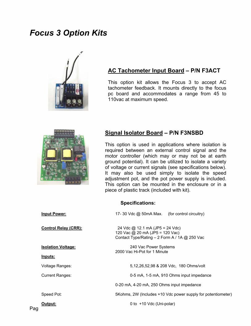
AC Tachometer Input Board – P/N F3ACT
This option kit allows the Focus 3 to accept ACtachometer feedback. It mounts directly to the focuspc board and accommodates a range from 45 to110vac at maximum speed.
Input Power:
Control Relay (CRR):
Isolation Voltage:
Inputs:
Voltage Ranges:
Current Ranges:
Speed Pot:
Output:
Signal Isolator Board – P/N F3NSBD
This option is used in applications where isolation isrequired between an external control signal and themotor controller (which may or may not be at earthground potential). It can be utilized to isolate a varietyof voltage or current signals (see specifications below).It may also be used simply to isolate the speedadjustment pot, and the pot power supply is included.This option can be mounted in the enclosure or in apiece of plastic track (included with kit).
17
212C
20
0-
5K
Specifications:
- 30 Vdc @ 50mA Max. (for control circuitry)
4 Vdc @ 12.1 mA (JP5 = 24 Vdc)0 Vac @ 20 mA (JP5 = 120 Vac)
ontact Type/Rating – 2 Form A / 1A @ 250 Vac
240 Vac Power Systems00 Vac Hi-Pot for 1 Minute
5,12,26,52,98 & 208 Vdc, 180 Ohms/volt
0-5 mA, 1-5 mA, 910 Ohms input impedance
20 mA, 4-20 mA, 250 Ohms input impedance
ohms, 2W (Includes +10 Vdc power supply for potentiometer)
0 to +10 Vdc (Uni-polar)

Page 19
Focus Family Options
Remote Operator Station – P/N 2950-9068 /2950-9066
These NEMA 1 operator stations can be used to remotelycontrol Focus 1 and Focus 3 Motor Controllers. Two modelsare available as shown. Both units include a SpeedPotentiometer, a green normally open start button and a rednormally closed stop button. The 2450-9068 also includestwo two- position switches with two contacts, 1 normallyopen, 1 normally closed.
Remote Percent Speed Meter – P/N 2450-9024
This meter may be used to remotely display the motor speedin percent of maximum speed. Included is a universalcalibration board. The 4 1/2-inch meter is mounted in a NEMA1 wall mountable steel enclosure.
Remote RPM Speed Meter – P/N 2450-9021
This meter may be used to remotely display the motor RPM(up to 2000rpm). Included is a universal calibration board. The4-1/2inch meter is mounted in a NEMA 1 wall mountable steelenclosure.
Ten-Turn Precision Speed Potentiometer – P/N 6160-9001
This is a multi-turn speed potentiometer. It provides a vernierscale for precise and repeatable speed setting. A locking tab isprovided to prevent in advertent speed changes. It may bemounted in either of the Focus 1 and Focus 3 enclosures or theRemote Operator Station described above.
RunJog
AutoMan
Speed
Start
Stop
Speed
Start
Stop
Page 20
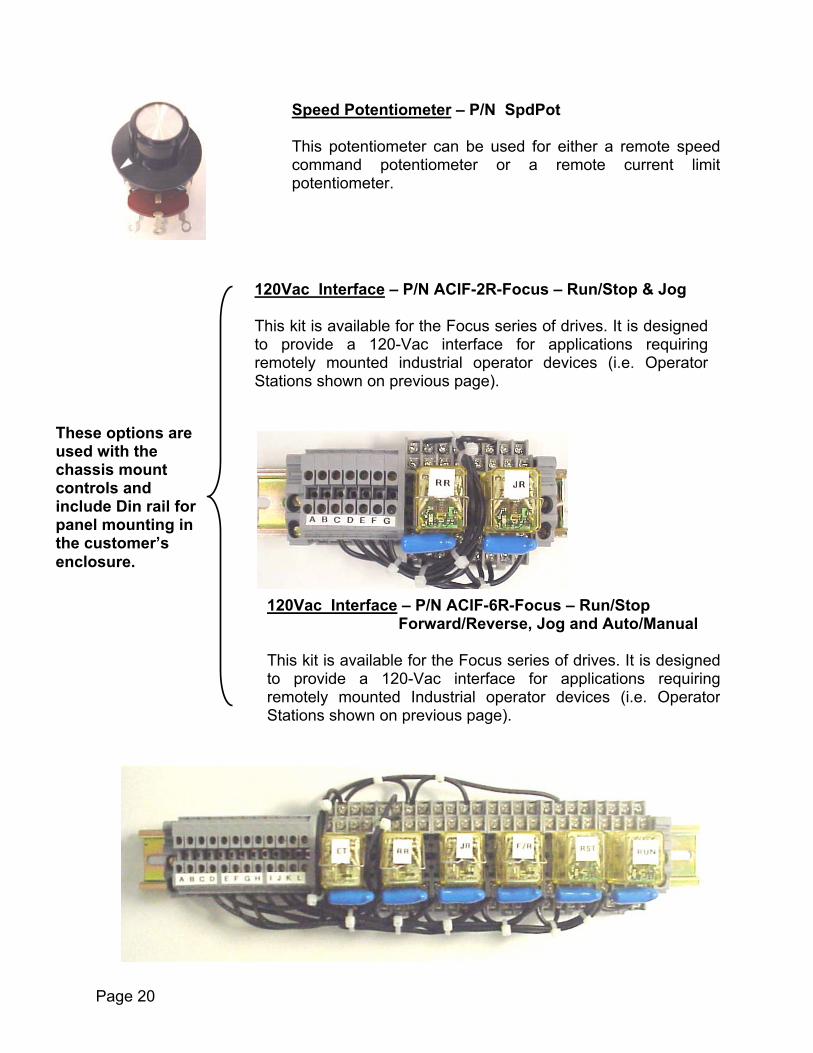
These options areused with thechassis mountcontrols andinclude Din rail forpanel mounting inthe customer’senclosure.
Speed Potentiometer – P/N SpdPot
This potentiometer can be used for either a remote speedcommand potentiometer or a remote current limitpotentiometer.
120Vac Interface – P/N ACIF-2R-Focus – Run/Stop & Jog
This kit is available for the Focus series of drives. It is designedto provide a 120-Vac interface for applications requiringremotely mounted industrial operator devices (i.e. OperatorStations shown on previous page).
120Vac Interface – P/N ACIF-6R-Focus – Run/Stop Forward/Reverse, Jog and Auto/Manual
This kit is available for the Focus series of drives. It is designedto provide a 120-Vac interface for applications requiringremotely mounted Industrial operator devices (i.e. OperatorStations shown on previous page).

Customer Connections & Start-Up
Start-up Guidelines
STEP 1: Receiving & STEP 2: Drive InstallaSTEP 3: Power WirinSTEP 4: Control WiriSTEP 5: Jumper ProgSTEP 6: PotentiometSTEP 7: Start-up of D
Improper procedures can result ielectrical maintenance technicians
precautions should be perm
Read this manual in its entirety, paying pin each section before installin
Installation of this equipment musCode and all other applicable resizing, and short circuit protectinstallation or operation of this cequipment.
Hazardous voltages may be presencan result in personal injury or equ
When performing visual inspectioturned off and locked out. Hazarturned off. The drive contactor doe
n personal injury or equipment damage. Only qualified familiar with electronic drives and their standard safety
itted to install, start-up, or maintain this apparatus.
Inspection . g ng ramm
er Adrive
t be gionaion montro
t on ipme
ns andous s not
NOTEarticular attention to the Warnings and Cautionsg, starting, or maintaining this drive.
Page 21
tion Page 8. . Page 21
Pages 22-25Pages 26-33
ing Pages 34-38justments Pages 40-46
Page 49-55
done in accordance with the National Electricall or local codes. Proper grounding, conductorust be installed for safe operation. Improperl may cause injury to personnel or damage to
external surfaces of ungrounded controls. Thisnt damage.
d maintenance, the incoming AC power must bevoltages will be present until the AC power is remove hazardous voltages when opened.

Page 22
Incoming Power RequirementsA remote fused AC line disconnects or circuit breaker installed ahead of the control is requiredby the NEC (National Electrical Code). The control is designed to accept single-phase AC linevoltage.
Grounding
The control must be connected to earth ground either via mounting screws provided by anenclosure or chassis-installed screw or by using the Earth Ground lug provided on the driveheatsink, for safety of operating personnel. The ground wire should be of the same gauge asthe AC Input wires and must be connected to the panel or enclosure frame for personal safety.
Wiring Guidelines for Focus DC DrivesCheck drive nameplate data for conformance with AC power source and motor
AC Input DC Output Shunt FieldCatalog HP Fusing Max Wire Armature Armature Wire Field Field Wire
Part # Volts Amps AWG Volts Amps AWG Volts Amps AWGF3N2C ¼ -1
½-215
Amp250Vac
120240
1414
#14 90180
1010
#14 100200
11
#14
F3N2E ¼ -1½-2
15Amp
250Vac
120240
1414
#14 90180
1010
#14 100200
11
#14
F3N5CF3N5E
3 40Amp
500Vac
240 21 #10 180 15 #10 200 1 #14
F3N5CF3N5E
5 40Amp
500Vac
240 35 #8 180 25 #8 200 1 #14
Notes: All wiring based on 75° C copper wire, types FEPW, RH, RHW, THHW,THW, THWN, XHHW, USE, ZW
Wire gauge size based on 30° C maximum ambient and no morethan three conductors in a raceway or cable and 1.25 service factor.
Please refer to National Electric Code Table 310-16 for additionalinformation.
Wiring must also meet any Local Codes. Do not place knife switches, polarity reversing switches, reversing contacts inthe armature or field circuits.
During normal operation, keep all covers in place and cabinet doors shut.

Page 23
Motor Thermal Switch
For Motor Thermostat wiring, see the “Control Wiring” section.
Wrong Motor Rotation
If the motor rotates in the wrong direction, one of the following changes will correct it:
Exchange Al and A2 output Motor Armature leads.Or
Exchange Fl and F2 Motor Shunt field leads.
If DC Tachometer Feedback is being used, Tach wires will also need to be swapped.
Installation of Option Kits
Do not install option kits until you have verified the basic operation as outlined in theStart-Up section. Pre-installation of option kits before verification of basic drive operation will maketroubleshooting much more difficult. Option kits are often installed incorrectly and onecannot determine if the drive was functional before kits were installed.

Page 24
Drive Power Wiring
F+
( t
¼ - 2 HP Focus 3 Models F3N2E & F3N2C
F+ F- A- A+
EarthConnection
AC LineInput
A+ & A- are the motorArmature leads
& F- are a shunt woundmotors Field leads
hey will not be present onPermanent Magnet or
Universal Motors )

Drive Power Wiring3 - 5 HP Focus 3 Models
F3N5E & F3N5C
F+
( th
EarthConnection
AC LineInput
F+ F- A+ A-
A+ & A- are the motorArmature leads
& F- are a shunt woundmotors Field leads
ey will not be present onPermanent Magnet or
Universal Motors )
Page 25
Page 26
Control Wiring
TERMINAL CONNECTIONS (TB2) & DESCRIPTIONS
Pin Number
1 +24 Vdc Supply: Powers the logic inputs to the drive. It is not intendedfor it to be used to power external circuits. External use will void warranty.
2 Tie Point: It has no internal connections and is used as a tie point forthe Motor Thermal or Stop button connection.
3 Run Input: When +24 Vdc is applied to this terminal, the Run relay picksup, the Speed loop and the Current loop are enabled, and the clamp onthe SCR firing circuits is released.
4 Run Relay Contact Output: Normally Open connection. Rated:0.5amps @ 120VAC for non-inductive loads. It can be used as the seal-incontact in a three-wire run circuit or as the run contact feedback in a two-wire system.
5 Run Relay Contact: Relay common connection.
6 Run Relay Contact: Normally Closed connection. Rated: 0.5amps @120VAC for non-inductive loads.
7 Jog Input: When +24 Vdc is applied to this input, the output of theaccel / decel circuit is electronically disconnected from the speed loop andthe jog speed command (from the jog speed pot) is electronically switchedin. This jog speed command can be configured as a Thread speed(maintained jog speed) by jumpering terminals TB2-3 & 4 in addition to theRun/Jog connections already shown on page 30.
8 Jog Potentiometer Supply voltage input: This terminal is typicallyconnected to the +10 Vdc (TB2-9) speed pot supply when jog is required.
9 +10 Vdc Speed pot / Jog supply voltage: Maximum load is 5matherefore the recommended Jog Pot value would be 5K ohms
10 Standard Speed command input: Typically this input is connected tothe wiper of the speed pot wiper. Input impedance: 20Kohm.
11 Unused: This terminal is not used with the non-regen F3N drives.
Page 27
TERMINAL CONNECTIONS (TB2) & DESCRIPTIONS
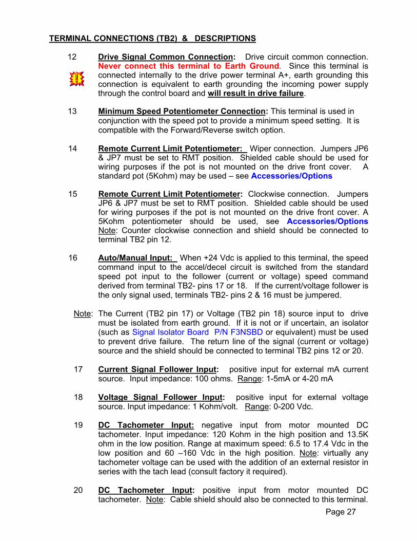
12 Drive Signal Common Connection: Drive circuit common connection.Never connect this terminal to Earth Ground. Since this terminal isconnected internally to the drive power terminal A+, earth grounding thisconnection is equivalent to earth grounding the incoming power supplythrough the control board and will result in drive failure.
13 Minimum Speed Potentiometer Connection: This terminal is used inconjunction with the speed pot to provide a minimum speed setting. It iscompatible with the Forward/Reverse switch option.
14 Remote Current Limit Potentiometer: Wiper connection. Jumpers JP6& JP7 must be set to RMT position. Shielded cable should be used forwiring purposes if the pot is not mounted on the drive front cover. Astandard pot (5Kohm) may be used – see Accessories/Options
15 Remote Current Limit Potentiometer: Clockwise connection. JumpersJP6 & JP7 must be set to RMT position. Shielded cable should be usedfor wiring purposes if the pot is not mounted on the drive front cover. A5Kohm potentiometer should be used, see Accessories/OptionsNote: Counter clockwise connection and shield should be connected toterminal TB2 pin 12.
16 Auto/Manual Input: When +24 Vdc is applied to this terminal, the speedcommand input to the accel/decel circuit is switched from the standardspeed pot input to the follower (current or voltage) speed commandderived from terminal TB2- pins 17 or 18. If the current/voltage follower isthe only signal used, terminals TB2- pins 2 & 16 must be jumpered.
Note: The Current (TB2 pin 17) or Voltage (TB2 pin 18) source input to drivemust be isolated from earth ground. If it is not or if uncertain, an isolator(such as Signal Isolator Board P/N F3NSBD or equivalent) must be usedto prevent drive failure. The return line of the signal (current or voltage)source and the shield should be connected to terminal TB2 pins 12 or 20.
17 Current Signal Follower Input: positive input for external mA currentsource. Input impedance: 100 ohms. Range: 1-5mA or 4-20 mA
18 Voltage Signal Follower Input: positive input for external voltagesource. Input impedance: 1 Kohm/volt. Range: 0-200 Vdc.
19 DC Tachometer Input: negative input from motor mounted DCtachometer. Input impedance: 120 Kohm in the high position and 13.5Kohm in the low position. Range at maximum speed: 6.5 to 17.4 Vdc in thelow position and 60 –160 Vdc in the high position. Note: virtually anytachometer voltage can be used with the addition of an external resistor inseries with the tach lead (consult factory it required).
20 DC Tachometer Input: positive input from motor mounted DCtachometer. Note: Cable shield should also be connected to this terminal.

P
The F3N drive control circuitry is not isolated *. No points in the controlcircuitry, including common, should be connected to earth ground unless
specifically shown on the supplied wiring diagrams. No grounding connectionsshould be made on the terminal block. Improper connections to ground,
including speed potentiometer connections, will result in immediate controlfailure and will void the factory warranty.
* See How to Achieve Isolation on page 68 of this manual
EnclosedUnitsWire Entry
ChassisUnitsWire Entry
Signal &Control WiringEntry
Terminal Block (TB2)
Installation
On chassis drives, the terminal block(TB2) is installed so that control wires areinserted into the terminal point from theright side of the block. For enclosed drives,the terminal block must be installed sowires extend up (900 angle) from the drivePC board. lf the control wires extend outto the side, there is not sufficientclearance space for the enclosurecover.
If the customer supplied motorthermal is not used, pins 1 & 2 must bejumpered or the drive will not start.
NOTE:
Shielded wire (2 or 3 conductor) isrecommended for speed command andother signal wire connections. Shieldsshould be taped off at the remote end. Atthe drive, connect shields to the circuitcommon, route wire away from highcurrent lines (i.e. AC lines and armaturewiring).
Recommended Cables and pots areavailable from :Control Techniques Service Center @ 1-800-367-8067
age 28

Page 29
Terminal Strip Connections
Enclosed Model
Standard Start / Stop & Speed Potentiometer Connections
Chassis Model
The next three pages show various configurations of operator control devices andspeed (or current) adjustment potentiometers. These can be used on Chassis models,which is typically the case, or the Enclosed models, which would require possibleenclosure and internal wiring changes. The two wire configuration (top of next page) iscommonly used for remote contol of the drive (i.e. PLC control). These connectionsmust be isolated from earth ground.
The Chassis Model has nooperator devices connected tothe drive control terminal strip.The only connections madeare connections from terminal#3 to #4 which is required forthree wire Start/Stop controls.
The Speed Potentiometer issupplied “loose” with the drive.
Drive will not startwithout this
The Start/Stop SwitchAnd the SpeedPotentiometer aresupplied as shown onthe drive cover

Page 30
Optional Terminal Strip ConnectionsNote: It is strongly recommended that all remote control connections to the drive (i.e. speed pot,start / stop etc.) are wired with shielded cable for noise immumity. These are all low voltagesignals. No connections are to be tied to earth ground.
Two Wire ON / OFF
with remote 0 to +10Vdc Speedcommand ( this signal must beisolated ! )
Three Wire Start / Stop
With Uni-polar Speed Potentiometer( DO NOT Connect Shield to EarthGround ! )
Three Wire Start / Stopwith Run / Jog Selector Switch
With Uni-polar Speed Potentiometer( DO NOT Connect Shield to EarthGround ! )
Drive will not Start without this!
Drive will not Start without this!

Typical Terminal Strip Connections Note: It is strongly recommended that all remote control connections to the drive (i.e. speed pot,start / stop etc.) are wired with shielded cable for noise immumity. These are all low voltagesignals. No connections are to be tied to earth ground.
Three Wire Start / Stopwith Run / Jog Selector Switch
With Uni-polar Speed Potentiometer( DO NOT Connect Shield to EarthGround ! )
WithManual / Auto Speed command SelectorSwitch(Manual – Speed Pot)(Auto – Either Current Signal
or Voltage Signal)
WithDC Tachometer Feedback
DO NOT Connect Shield to Earth Ground !
Drive will not Start without this!
Shielded cable should be 3 conductor with overall shield w/pot end tied off and dressed.Cable and pots are available from Control Techniques Service Center @ 1-800-367-8067
Cable P/N 3CONCBL-XXX (XXX in feet)
Page 31

Typical Terminal Strip Connections Note: It is strongly recommended that all remote control connections to the drive (i.e. speed pot,start / stop etc.) are wired with shielded cable for noise immumity. These are all low voltagesignals. No connections are to be tied to earth ground.
Three Wire Start / StopWith Run / Jog Selector Switch
WithUni-polar Speed Potentiometer
WithRemote Current Limit PotentiometerThis potentiometer is available fromControl Techniques; see accessories section,page 20
WithDC Tachometer Feedback
( DO NOT Connect Shieldsto Earth Ground ! )
DO NOT Connect Shield to Earth Ground !
Drive will not Start without this !
Shielded cable should be 3 conductor with overall shield w/pot end tied off and dressed.Cable and pots are available from: Control Techniques Service Center @ 1-800-367-8067Cable P/N 3CONCBL-XXX (XXX in feet)
Page 32

Standard Unipolar Speed Potentiometer Wiring
Do
CCW=counterclockwise
Wiper
CWCCW
9
10
12
+10vdc
Ref.
CommonSpeed PotRear View
Cable should be 3 conductor with overall shield w/pot endtied off and dressed. Cable and pots are available from: Control Techniques Service Center @ 1-800-367-8067
Cable P/N 3CONCBL-XXX (XXX in feet)
Speed Potentiometer P/N SpdPot
Page 33
Not Connect shield to Earth. This will result in permanent damage tothe Drive and will not be covered under WARRANTY
Page 34
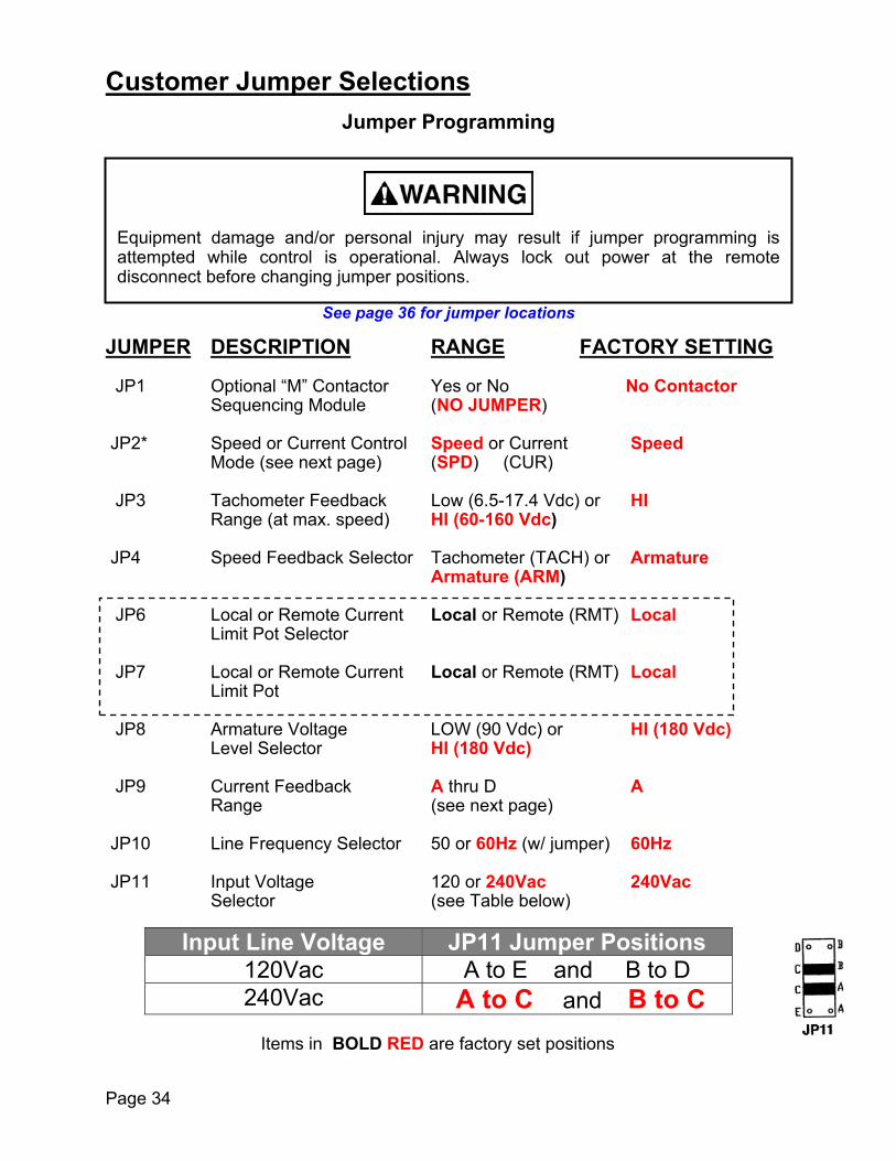
Customer Jumper SelectionsJumper Programming
See page 36 for jumper locations
JUMPER DESCRIPTION RANGE FACTORY SETTING
JP1 Optional “M” Contactor Yes or No No ContactorSequencing Module (NO JUMPER)
JP2* Speed or Current Control Speed or Current SpeedMode (see next page) (SPD) (CUR)
JP3 Tachometer Feedback Low (6.5-17.4 Vdc) or HIRange (at max. speed) HI (60-160 Vdc)
JP4 Speed Feedback Selector Tachometer (TACH) or ArmatureArmature (ARM)
JP6 Local or Remote Current Local or Remote (RMT) LocalLimit Pot Selector
JP7 Local or Remote Current Local or Remote (RMT) LocalLimit Pot
JP8 Armature Voltage LOW (90 Vdc) or HI (180 Vdc)Level Selector HI (180 Vdc)
JP9 Current Feedback A thru D ARange (see next page)
JP10 Line Frequency Selector 50 or 60Hz (w/ jumper) 60Hz
JP11 Input Voltage 120 or 240Vac 240VacSelector (see Table below)
Input Line Voltage JP11 Jumper Positions120Vac A to E and B to D240Vac A to C and B to C
Items in BOLD RED are factory set positions
Equipment damage and/or personal injury may result if jumper programming isattempted while control is operational. Always lock out power at the remotedisconnect before changing jumper positions.

Current Feedback Range (JP9)
FOCUS Catalog DC Output Current JP9Number (Amps) Jumper Position
2.7 No Jumper(1/4 – 2 HP) 5.5 A
F3N2C 6.4 BF3N2E 7.5 C
10 D6.6 No Jumper
(3 – 5 HP) 13.8 AF3N5C 16 BF3N5E 18.75 C
25 D
Current Control Mode
Focus 3 Drives can be configured to operate in the Current Control Mode which is oftenreferred to as making the drive a “Current Regulator”. Since motor torque is directlyproportional to the armature current, a drive configured as a Current Regulator is oftenreferred to as a “Torque Regulator”.
*If using the Focus drive as Torque Regulator, make the followingadjustments:
JP2: Select current (CUR) controlJP4: Select tachometer (TACH) feedback, but do not use a tachometer.JP9: Select the appropriate current feedback range.
ACCEL and DECEL pots: Set to full counterclockwise position. LOCAL CURRENT LIMIT pot: Set to full clockwise position.
In torque control mode, the motor smotor and the torque level set on thset to a level higher than what is respeed until either the load from thedrive reaches its maximum output vo In the case of a lightly loaded motor the motor could accelerate to almo
In this mode the user be aware of t
peed is determined by how much load there is on thee drive. If torque in the motor (as set by the Drive) isquired to move the load, the motor will accelerate in motor increases to the level set by the drive or theltage (as set by the line voltage).
,st twice-base speed under these conditions.
his and MUST PROVIDE OVERSPEED PROTECTION.
Page 35

Page 36
Programming Jumper Locations
Armature /TachometerFeedbackSelectorJP4
TachometerFeedbackRangeSelectorJP3
ArmatureVoltageRangeSelectorJP8
Current LimitPot selectionLocal or RemoteJP6 / JP7
Optional MotorContactor controlconnection JP1
MaximumOutputCurrentSelectionJP9
RegulationModeSpeed / CurrentJP2
50 / 60 HzOperation(in = 60Hz)JP10
A+L1 L2 F+ F- A- X
JP11AC InputRangeSelection

Jumper Programming
Photo shownjumpered for120Vac input
JP3-Tach Feedback Range
Lo - 6.5 to 17.4 Vdc Hi - 60 to 160 Vdc
JP4 -------- Feedback Selector
Tachometer (Tach) Armature (Arm)
JP8 --------- Armature Voltage
90 Vdc 180 Vdc
JP11 ---- Input Voltage
120 Vac A to E &
B to D
240 Vac A to C &
B to C
Bold Fonts indicateFactory Settings
Page 37

P
JP9 -- Max Output Current (100%)
Removed - 2.7 A A – 5.5 A
B – 6.4 AC – 7.5 AD – 10A
Select based on Armaturerequirements
age 38
JP6 & JP7 --- Remote Current Limit
Pot Select
Local – Uses Current Limit pot on Control Board
Remote – Uses remote Current limit Potentiometer
Bold Fonts indicate Factory Settings

LED Status Indicators
Run LED – This red led will illuminate any time the run relay is energised
Curr Lmt (Current Limit) LED – This yellow led will illuminate any time one of the three conditions are met:
1. The drive is at the maximum outputcurrent as set by the current limitpotentiometer and the selected positionof JP9
2. The motor is at the maximum outputvoltage as possible based on the supplyvoltage.
3. The motor armature is open circuit( no motor connected )
CurrentLimit LED
RunLED
Page 39

Page 40
Internal Adjustments I Potentiometers
Jumpers and pots shown in Factory positions
A+L1 L2 F+ F- A- X
CurrentStability(ISTB)
VelocityStability(VSTB)SpeedLoopOffset
MaximumSpeed
IRCompensation
Current Limit
AccelerationTime
Jog Speed
DecelerationTime
MinimumSpeed
FollowerZeroBias Adjust
VoltageFollowerGain Adjust
CurrentFollowerGain Adjust
Factory CalibrationDo Not Adjust !

Page 41
Basic Customer Adjustments
Maximum Speed (MAX SPD)
The MAX SPD pot sets the maximum motor speed (80-120% of motor basespeed) allowed. It is factory preset to the midway position. Note: Do not exceedmotor nameplate maximum speed rating. With the motor running, turn the speedpot on the drive enclosure cover/operator control panel fully clockwise whilemonitoring actual motor RPM or by measuring the Armature Voltage on A+ & A-.Then, adjust the MAX SPD pot on the control board to set the desired maximummotor speed. Do not exceed the motors Armature Voltage nameplate rating.
Minimum Speed (MIN SPD)
The MIN SPD pot sets the minimum speed (0-30% of maximum speedsetting) at which the motor will run. It is factory preset at its full counterclockwiseposition. With the motor running, turn the speed pot on the drive enclosurecover/operator control panel fully counterclockwise. Adjust the MIN SPD potclockwise until the desired lowest motor speed is reached.
Acceleration and Deceleration Times (ACCEL / DECEL)
Adjust the ACCEL and DECEL pots clockwise to increase the linearacceleration and deceleration times (0.3-30 seconds). These adjustments areindependent from each other. Note: Controlled deceleration time occurs when thespeed pot is turned down, but not when the start/stop switch is placed in the STOPposition. Note: When the drive is used in torque (current) control mode, theACCEL/DECEL pots adjust how quickly the motor torque level changes as themain torque pot is varied.
Local Current Limit (LOC ILMT)
Set the LOC ILMT pot to limit the motor armature current to 150% or less ofthe motor nameplate rating. It should represent the lowest level consistent withsatisfactory operation. The pot is factory preset at 150% of the range selected byjumper JP9 (A-D).
The yellow Current Limit LED indicator light on the drive control boardilluminates when the armature current reaches 95-100% of the current limit setting.
Jog Speed (JOG SPD)
Adjust the JOG SPD pot clockwise to increase the speed (0-30% of full speedreference) at which the motor will run when in jog mode. It is factory preset to itsfull counterclockwise position.

Page 42
Basic Customer Adjustments
Accelerationand
DecelerationTime adjustments
Local Current Limit
Limits maximum Output Current
MIN SPD
Adjust for minimum Motor spee
MAX SPD
Adjust for maximum Motor speed
JOG SPEEDSets JogSpeed
d

Page 43
Additional Tuning AdjustmentsInternal Resistance Compensation ( IR COMP )
Compensation pot is used to overcome the motor’s natural tendency to slowdown as the load increases. If the motor slows down excessively as it is loaded, adjustthe IR COMP pot clockwise to recover speed lost during the loaded condition. Themotor will oscillate in speed or “hunt” if the IR COMP pot is adjusted too far clockwise.If this pulsing of speed occurs, adjust the IR COMP pot counter clockwise until themotor speed stabilizes.
If JP4 is set in the TACH position indicated tachometer feedback is being used,turn the IR COMP pot fully counter clockwise otherwise instability will occur.
Note: If the drive is using the voltage or current signal follower, perform theseadjustments with the Auto/Manual switch in the Manual position.
Velocity Stability (VEL STAB)
The VEL STAB pot helps match the dynamic characteristics of the drive to thedynamic characteristics of the DC motor and its load. The drive’s outer velocity loopincludes an electrical “lead” circuit to compensate for the mechanical “lags” that exist inboth the DC motor and its driven mechanical system. The VEL STAB pot adjusts thetime constant of this lead circuit.
Clockwise rotation causes the drive to respond more quickly to speedcommand/speed feedback changes but increases the overshoot experienced by thedrive. Counterclockwise adjustment of this pot dampens the drive response. It is factorypreset at the midway position.
Current Stability (ISTAB)
The ISTAB pot matches the dynamic characteristics of the drive to the dynamiccharacteristics of the DC motor armature. The drive’s inner current loop includes anelectrical “lead” circuit to compensate for the electrical “lag” that exists in the DC motorarmature current. The ISTAB pot adjusts the time constant of this lead circuit.
In torque (current) control applications, the velocity loop is bypassed and thecurrent loop is used. For speed (velocity) control applications, the current loop is fedfrom the output of the velocity loop.
The current loop responds to current changes quickly. Therefore, the ISTAB potis very sensitive and harder to adjust properly. Clockwise rotation causes the drive torespond more quickly to current changes, but the factory shipped setting is usuallyadequate for most applications.
Speed Loop Offset (SPD OFFSET)
This pot is used to zero out any offsets in the speed loop amplifier. With thespeed pot set to zero (as well as the Min Spd pot, if used), adjust the SPD OFFSET soany “creep” in the motor speed is eliminated with zero speed command. It is factorypreset to its midway position.

Page 44
Additional Tuning Adjustments
*** Consult Control Techniques Technical Support f
Current Stability(ISTB)
Adjust for currentloop stability
A
Ad
Velocity Stability(VSTB)
djust for speed loopstability
IR Comp
Adjust for motor speeddroop due to load
Factoryjustment***
onlyDO NOTADJUST
Speed Loop Offset
Adjust for zero creepspeed
or re-adjustment procedure.

Page 45
Optional Tuning Adjustments
The following adjustments are only required when either the current follower input (i.e.4-20 mA input) or the voltage follower input (i.e. tachometer follower) is used. Only oneof these inputs may be used. Terminal #16 must be tied to +24 Vdc (terminal #1) toactivate the follower input speed command; typically this selection is made by theAuto/Manual selector switch (see page 31) .
Signal Follower Zero Bias (BIAS) used with Voltage Input (TB2-18)
The BIAS pot prevents “creep” in the motor speed by eliminating any unwantedoffset voltage levels in the voltage source. It may also be used to add a slight offset tothe voltage signal.
Signal Follower Zero Bias (BIAS) used with Current Input (TB2-17)
Adjust the BIAS pot so the drive is at zero speed when the minimum currentsignal follower speed command (4-20 or 1 –5 mA) is applied.
If a 4-20mA speed command is required, use the optional signal isolationboard (F3NSBD).
Voltage / Speed Signal Follower Gain (SP REF GAIN)
The SP REF GAIN pot calibrates the User supplied Voltage Signal Followerspeed command (0 - 200 Vdc) so the motor reaches its rated voltage/speed when theinput voltage signal is set to its maximum value. It is factory preset to its fullcounterclockwise position.
Current Signal Follower Gain (IREF GAIN)
The IREF GAIN pot calibrates the User supplied Current Signal Follower speedcommand ( 1-5mA or 4-20mA ) so the motor reaches its rated voltage/speed when thecurrent signal is set to its maximum value. It is factory preset to its full clockwiseposition.

Page 46
Optional Tuning Adjustments
Current Ref Gain Speed Ref Gain Zero Bias

Page 47

Page 48

Start-up Guide Worksheet
At this po
Obtain the following info
Focus Drive Model
F3N2C or F3NF3N5C or F3N
a) AC Input Line Voltage
b) Motor Nameplate Infor
c) Type of Speed Feedba
Focus drives come to you facmotor is equipped with Tachomthat you first run your motor umotors maximum speed in tachometers output to verify tha
d) Regulation Mode
Focus drives come to you faccommon case. Even if your asuggest that you first run youproper operation in the Speed m
Improper procedures can result inmaintenance technicians familiarshould be permitted to install, sta
personal injury or equipment damage. Only qualified electrical with electronic drives and their standard safety precautionsrt-up, or maintain this apparatus.
Page 49
int all INPUT POWER must be OFF !
rmation:
2E Drive Serial Number 5E Drive Part Number _____________
240 Vac 120 Vac
mation: Armature Voltage _________Vdc Armature Current _________A Field Voltage _________Vdc Field Current _________A Rated RPM _________ rpm
ck Armature Voltage ( most common case )DC TachometerAC Tachometer (Option Board Required)
tory set for Armature Voltage feedback. Even if youreter for Speed feedback, we would strongly suggest
sing Armature Voltage initially. After you have set theArmature Voltage feedback, you can check yourt it producing the correct output before actually using it.
Speed ( most common case )Torque
tory set for Speed Regulation mode which is the mostpplication requires Torque control, we would stronglyr motor Speed Control initially. After you have verified
ode, you could then switch over to Torque mode.

Page 50
Focus 3 Jumper Setup Worksheet
Refer to the data recorded on the previous page for this worksheet
Refer to your motor nameplate data.
STEP 1 Does your motor have a shunt field winding? If No go to STEP 5 otherwise go on.
STEP 2 Is your motor field current greater than 1.1A? If No, go to STEP 3
If Yes STOP The Focus 3 Field Supply rectifier will be damaged!!! Call Tech Support for a solution.
STEP 3 If your motor field voltage is 100 Vdc,then you must use 120 Vac for Input Power ----- Set JP11 as shown
and Set JP8 to Low then go to STEP 7
If you must use 240 Vac ----- Call Tech Support for a solutionotherwise go to STEP 4
STEP 4 If your motor field voltage is 200 Vdc, then you must use 230 Vac for Input Power ---- Set JP11 as shown
and Set JP8 to Hi then go to STEP 7
otherwise STOP ---- Call Tech Support for a solution
STEP 5 If your motor armature voltage is greater than 110 Vdc,then you should use 230 Vac for Input Power ---- Set JP11 as shown
and Set JP8 to Hi then go to STEP 7
If you must use 120 Vac ---- Call Tech Support for a solution
otherwise go to STEP 7
STEP 6 If your motor armature voltage is less than 110 Vdc, then you must use 115 Vac for Input Power ----- Set JP11 as shown
and Set JP8 to Lo then go to STEP 7
: :
: :
Page 51
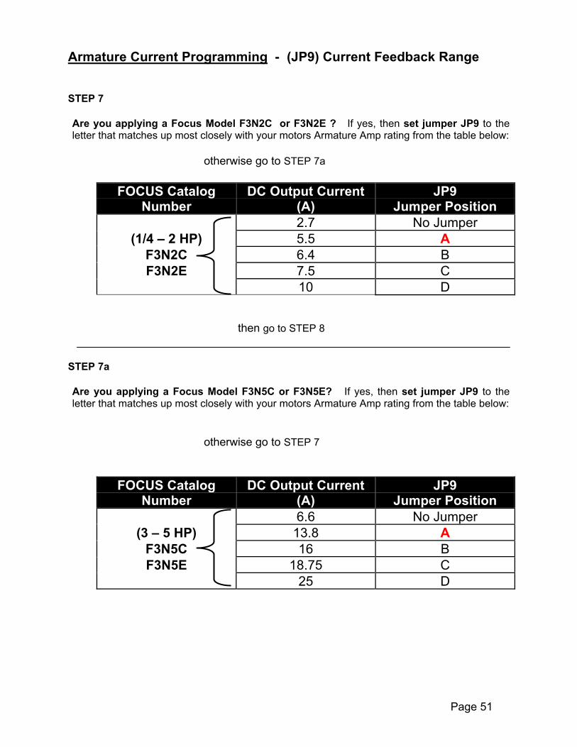
Armature Current Programming - (JP9) Current Feedback Range
STEP 7
Are you applying a Focus Model F3N2C or F3N2E ? If yes, then set jumper JP9 to theletter that matches up most closely with your motors Armature Amp rating from the table below:
otherwise go to STEP 7a
FOCUS Catalog DC Output Current JP9Number (A) Jumper Position
2.7 No Jumper(1/4 – 2 HP) 5.5 A
F3N2C 6.4 BF3N2E 7.5 C
10 D
then go to STEP 8
STEP 7a
Are you applying a Focus Model F3N5C or F3N5E? If yes, then set jumper JP9 to theletter that matches up most closely with your motors Armature Amp rating from the table below:
otherwise go to STEP 7
FOCUS Catalog DC Output Current JP9Number (A) Jumper Position
6.6 No Jumper(3 – 5 HP) 13.8 A
F3N5C 16 BF3N5E 18.75 C
25 D

Page 52
Initial Start-Up
The following procedure is to verify proper operation of the drive in its simplest form asa basic speed regulator with no option kits installed. It is assumed that the drive is in its“out of box” condition with respect to jumper programming with the exception of whatwas just changed in the previous pages, jumper setup worksheet.
Installation of Option Kits
Do not install option kits until you have verified the basic operation as outlined in theStart-Up section. Pre-installation of option kits before verification of basic drive operation will maketroubleshooting much more difficult. Option kits are often installed incorrectly and onecannot determine if the drive was functional before kits were installed.

Page 53
Initial Start-Up con’t
A minimal number of connections are made to the terminal strip (see diagramsbelow). If the drive is an enclosed unit with operator devices (start/stop andspeed pot) only the jumper from terminal block TB2-1 to TB2-2 needs to bemade.
a) Type of Speed Feedback; In this procedure, leave jumper in armaturefeedback (JP4 = ARM).
b) Regulation Mode: In this procedure, leave jumper in speed regulation (JP2 = SPD).
For Chassis Units Only
1
3
7
8
9
close to run
Jog enable
+10vdc
Drive run enable
Jog ref0 to 30%
A+
A-
F+
F-
FE1
FE2
Regenonly
A1
A2
F1
F2
MotorArmature
Motor Field
FOCUS 3Chassis Unit
Note:PermanentMagnet Motorsdo not haveField F1 & F2,connections
1
45
9
Drive run enable
A+
A-
F+
F-
FE1
FE2
Regenonly
A1
A2
F1
F2
MotorArmature
Motor Field
FOCUS 3Enclosed Unit
2
3
Stop
Start
Speed Pot
Enclosure Cover
Add this Jumper
1012
ADD THISJUMPER For Enclosed Units Only

Page 54
Initial Start-Up con’t
1. Adjust Current Limit Pot labeled LOC ILMT, fully counter-clockwise. Adjust Speed pot (enclosed unit) approximately 1/3 turn clockwise (from full CCW position) Adjust Jog pot (chassis unit) fully clockwise.
Power can now be Applied !
2. Start drive. Run light (red) and Current limit light (yellow) are illuminated.
3. Slowly adjust current limit pot clockwise (~1/4 turn) while watching motor shaft.Verify that the motor rotates in the desired direction and that the motor slowlyaccelerates to about 30% of rated speed (also note that current limit light goes outwhen motor is running steady). If the motor rotates in the wrong direction, stop drive,REMOVE AC POWER and then reverse the field leads, F1 and F2.Re-apply power and repeat this step.
4. Stop Drive and Turn off AC Power.
Basic Setup with Tachometer Feedback (go to step #8 if NO tachometer)
5. The drive can now be set up for tachometer feedback if required. Set JP4 to “Tach” positionConnect tachometer signal to drive (- to #19, + to #20)Set JP8 to “Hi” if the following calculated voltage is in the range 60 to 160 Vdc.Set JP8 to “Low” if the following calculated voltage is in the range 6.5 to 17.4Vdc.Tach voltage at max speed = tach volts per 1000rpm X max motor rpm
1000If the calculated voltage is NOT in the ranges listed above, consult factory.
Repeat steps 1 to 2 above then proceed to step 6.
6. Slowly adjust current limit pot clockwise (~1/4 turn) while watching motor shaft.Verify that the motor rotates in the desired direction and that the motor slowlyaccelerates to about 30% of rated speed (also note that current limit light goes outwhen motor is running steady). If the motor continues to accelerate past ~30%speed, tachometer is probably connected backwards. Stop drive, Turn off ACPOWER and then reverse the tachometer leads, re-apply power and repeat thisstep. Stop Drive and Turn off AC Power when complete.
7. Drive can now be set-up for terminal strip connections as required by the particularapplication. Refer to pages 30-32 for typical Terminal Strip Connections.

Page 55
8. Only do the next Step if the Drive is to be configuration as of Current or TorqueRegulator. Otherwise Drive can now be set-up for terminal strip connections asrequired by the particular application. Refer to pages 30-32 for typical TerminalStrip Connections.
Basic Setup for Current (Torque) Regulator
9. If the drive is to be set-up as a Current (torque) Regulator, set jumper JP2 to“CURR” position and JP4 to “TACH” position but DO NOT connect a Tachometer.
The standard speed command input (TB2-#10) is now the drive current reference. Theaccel / decel adjustments on the control board will now control the rate of change ofcurrent.
Note that the drive is now controlling motor torque and NOT speed, therefore ifthe current reference is set to a higher level than the torque required by the load,
the motor will run to speeds in excess of rated motor speed. In applications where thisover-speed condition can occur (such as a web break in a simple re-winder) anexternal over-speed protection device must be added to the system.

Page 56
Focus 3 Trouble Shooting Guide
IMPORTANT SAFEGUARDS
All work on the drive should be performed by personnel familiar with it and itsapplication. Before performing any maintenance or troubleshooting, read theinstructions and consult the system diagrams. Only minor adjustments should benecessary on initial start-up, depending on the application. In addition, some commonsense maintenance needs to be followed.
KEEP IT CLEAN: The control should be kept free of dust, dirt, oil, causticatmosphere and excessive moisture.
KEEP IT COOL: The control should be located away from machines having ahigh ambient temperature. On panel mount controls, air flowacross heatsinks must not be restricted by other equipmentwithin the enclosure.
KEEP CONNECTIONS The equipment should be kept away from high vibrationTIGHT: areas that could loosen connections or cause chafing of
wires. All interconnections should be re-tightened at time ofinitial start-up and at least every six months.
The motor should be inspected amade:
A. See that both the inside and oucause added motor heating, an
B. If a motor blower is used, makeis free to rotate. If air filters arreplaced if they are disposabheating.
C. Inspect the commutator and bruthe proper brush grade is used
D. The motor bearing should be gof grease and maintenance freheating and failure. Consult the
THE DC MOTOR MAY BE AT LINE VNEVER ATTEMPT TO INSPECT, TO(SUCH AS THE BRUSHES) WITHOCONTROL AS WELL AS THE DC PO
MAKE SURE THAT ALL POWER SOURCES HAVE BELETHAL VOLTAGES EXIST INSIDE THE CONTROL ANMOTOR GENERATES VOLTAGE IN THE DRIVE EVENWITH THE CONTROL DRIVING A MOTOR. NEVER INST
OLTAGE EVEN WHEN IT IS NOT INOPERATION. THEREFORE,UCH OR REMOVE ANY INTERNAL PART OF THE DC MOTORUT FIRST MAKING SURE THAT ALL AC POWER TO THE
WER TO THE MOTOR HAS BEEN DISCONNECTED.
EN DISCONNECTED BEFORE MAKING CONNECTIONS OR TOUCHING INTERNAL PARTS.YTIME INPUT POWER IS APPLIED, EVEN IF THE DRIVE IS IN A STOP MODE. A TURNING
IF THE AC LINE IS DISCONNECTED. EXERCISE CAUTION WHEN MAKING ADJUSTMENTSALL OR REMOVE ANY PC BOARD WITH POWER APPLIED TO THE CONTROL
t regular intervals and the following checks must be
tside of the motor are not excessively dirty. This cand therefore, can shorten motor life.
sure that the air passages are clean and the impellere used, they should be cleaned at regular intervals orle. Any reduction in cooling air will increase motor
shes. Replace the brushes if needed. Make sure that.
reased per the manufacturer’s instructions as to typequency. Over greasing can cause excessive bearing instructions supplied with the motor for more details.

TROUBLESHOOTING OVERVIEWFast and effective troubleshooting requires well-trained personnel supplied with thenecessary test instruments as well as a sufficient stock of recommended spare parts.Capable electronic technicians who have received training in the control operation andwho are familiar with the application are well qualified to service this equipment.
Suggested Training
A. Study the system instruction manual and control drawings.B. Obtain practical experience during the system installation and in future servicing.C.Train in the use of test instruments.
Maintenance Records
lt is strongly recommended that the user keeps records of downtime, symptoms, resultsof various checks, meter readings, etc. Such records will often help a service engineerlocate the problem in the minimum time, should such services be required.
General Troubleshooting
The most frequent causes of drive failure are:
A. Loose or broken wire connections.
B. Circuit grounding within the interconnections or the power wiring.
C.Mechanical failure at the motor.
DO NOT make adjustments or replace components before checking all wiring. Alsomonitor all LED indicator lights before proceeding with troubleshooting checks, andcheck for blown fuses.
lt should be noted that modern solid state electronic circuitry is highly reliable. Oftenproblems, which appear to be electrical, are actually mechanical. It is advised that themotor be checked in the event of any drive problems. Refer to the motor owner’smanual for maintenance and repair procedures.
Notes for a Troubleshooting Technician
A minimum knowledge of system operation is required, but it is necessary to be able toread the system schematics and connection diagrams.
An oscilloscope may be needed to locate problem areas and to make adjustments.However, the majority of problems can be solved by using a multimeter and by partssubstitution.
WHEN A TEST INSTRUMENT IS BECHASSIS IS NOT GROUNDED EITCASE BEING IN CONTACT WITHTAKEN WHEN USING THE OSCILHOT TO GROUND WHEN CONNEC
ING USED, CARE MUST BE TAKEN TO INSURE THAT ITSHER BY A GROUNDING PLUG CONNECTION OR BY ITS A GROUNDED SURFACE. EXTREME CARE MUST BELOSCOPE SINCE ITS CHASSIS WILL BE ELECTRICALLYTED TO THE CONTROL SYSTEM.
Page 57

Page 58
BASIC TROUBLESHOOTINGThis paragraph contains a basic list of symptoms of an improperly functioning control.Included in the list are possible causes and corrective measures for each symptomdescribed.
CONTROL APPEARS TO BE DA. Terminals TB2-1 and –2 on t
a jumper or the Motor TheB. No AC power - apply AC powC. Blown line fuses - replace linD. Loose connections -turn off E. Control incorrectly wired - reF. Defective Start/Stop switch, replace bad components as requG. Speed potentiometer set to zLINE FUSES BLOW OR MAIN CIRCUA. Control is wired to AC voltage
voltage or use step-down tranB. Rectifier cube, field diodes on
shorted, or a short to ground C. Improper wiring or jumper proD. Defective main PC board com
Components )E. Motor shaft jammed - determF. Excessive carbon dust from
FUSES BLOW WHEN SPEED POTENA. Motor is overloaded - reducB. Motor is defective - consult
as required.C. Current limit adjustment set
ACCEL TIME IS MUCH LONGER THAA. Check Accel pot settingB Motor overloaded – reduce
DECEL TIME IS MUCH LONGER THAA. Check Decel pot settingB. Motor is being overhauled
MOTOR DOES NOT REACH FULL SPA. Motor is overloaded - correctB. Maximum Speed potentiome
clockwise.C. Low AC line voltage (more th
correct.D. Current limit set too low – re-E. Incorrect jumper programminF. Defective rectifier cube - replG. Motor brushes worn - replace
BEFORE PROCEEDING WITHACTIVITY, ALL POWER SOURC
ANY MAINTENANCE OR TROUBLE-SHOOTINGES MUST BE DISCONNECTED.
EAD:he main PC board not jumpered together - install eitherrmostat between these terminals.er and measure L1 and L2 for correct voltage.
e fuses.AC power and tighten connections.check all wiring.component on main PC board, or rectifier cube -ired. ( See Critical Components )ero - slowly advance from zero to begin motor rotation.
IT BREAKER TRIPS WHEN APPLYING AC POWER: exceeding control rating -rewire control to proper ACsformer. main PC board, motor winding or suppressor networkis present - locate and remove short.gramming during installation.ponent - replace as required. (See Critical
ine cause and correct.brushes in motor - determine cause and correct.
TIOMETER IS ADVANCED FROM ZERO:e load as required. motor instruction manual and repair or replace motor
too high - readjust
N EXPECTED:
or remove load and re-check
N EXPECTED:
by another motor in system or by inertia of the machine
EED: overload condition.ter (MAX) is set too low -adjust MAX potentiometer
an 10% below nominal) -check AC line voltage and
adjust.g of JP9 - follow programming procedure ace as required. (See Critical Components ) as specified in motor instruction manual.

Page 59
MOTOR RUNS IN WRONG DIRECTION:A. The Al and A2 output leads to the motor are incorrectly wired - exchange these leads.B. On shunt wound motors only the shunt field Fl and F2 leads are incorrectly wired – exchange these leads.
MOTOR DOES NOT MAINTAIN SPEED UNDER LOAD:A. IRCOMP potentiometer is set too low - adjust clockwise H. Motor is overloaded - correct overload condition.I. Incorrect jumper programming – check jumpers.J. Defective component on main PC board – replace (See Critical Components)K. Current limit set too low – readjust.L. Motor brushes worn - replace as specified in motor instruction manual.
MOTOR DOES NOT COME TO FULL STOP:A. Minimum Speed potentiometer (MIN) is set too high -readjust B. Defective speed or torque potentiometer, component on regulator PCboard, Start/Stop switch, or rectifier cube -replace as required. (See Critical Components)
NO SPEED CONTROL:M. Defective rectifier cube - replace as required (See Critical Components)N. Defective component on main PC board - replace as required. (See Critical
Components )O. Incorrectly wired or defective speed potentiometer - check the wiring.P. Incorrect jumper programming - check jumper programming.Q. If the control (after rechecking all the wiring for proper and secure connections) is
still inoperative, make the following voltage checks. Double check to make sure thatarmature leads Al and A2 are not grounded.
F. High resistance ground on motor armature
VOLTAGE CHECK CHARTStep Function Normal
VoltageReadings
Terminalor Point
Probable Cause
1with AC
Power “on”
Voltage toRectifiers
120 Vac 240 Vac±10% ± 10%
ACl AC2Onpowercube
Blown Fuses
2*Speed
command
0 to +10 0 to +10 Vdc Vdc 10-12 Defective speed
adjustmentpotentiometer orcircuit board assembly
3 Field SupplyVoltage
100 Vdc 200 Vdc +Fl-F2
Defective field diodesdefective encapsulatedbridge rectifierassembly
4* ArmatureVoltage
0-90 Vdc 0-1 80 Vdc+Al-A2
Defective encapsulatedbridge rectifier ass’y, orcircuit board assembly
*Depends on the setting of the speed adjustment knob

Page 60
Basic Test Setup – Light Bulb Test
It is fairly easy to test Focus Drives on the bench. One does not have to use a motor toverify basic operation. When working properly, the Focus basically creates a variablevoltage much like a light dimmer except the output is DC. The easiest way to check aFocus on the bench without a motor is to connect the Armature output to a resistiveload. One could use a 75 watt light bulb screwed into a light bulb socket base asshown below.
Basic Test Power Wiring
In order to test the Focus, one would need to setup the input for 115 Vac operation andfor basic Armature Voltage feedback. The drive should also be set for the lowestcurrent setting. Therefore before testing, one should record the settings before test sothat they could be reset back after the test.
75 W115VACLine Input

Page 61
Record Drive Set-up BEFORE performing Light bulb test
Basic Armature Circuitry Checkout
After the Focus is wired as shown on the previous page and the jumper set as indicatedabove, 115 Vac power could be applied and the Focus should cause the light bulb tovary in brightness from nothing to full brightness. One could measure the voltageacross the bulb and it should be about 90 Vdc at maximum brightness. This wouldverify the basic Start/Stop, Speed command, Power Supply, Regulator and PowerSections.
Field Supply Checkout
If one wants to check the Field Supply, power should be removed and the light bulbmoved over to the F+ and F- terminals (use a 75 W bulb or less for the field. Use ofgreater than 75 W could permanently damage the Field rectifiers). Then uponapplication of power, the light bulb should light to full brightness and the voltage acrossthe light bulb should measure about 100 Vdc.
If the Focus passes these basic tests, the drive should be OK and the driveshould be able to run a good motor at least in Armature Voltage feedback (JP4 in ARM).Reset jumpers back to the “Before Test Recorded Settings” except for JP4 and re-check.
If the motor has a shunt field, it should measure at least:
200 ohms if Nameplate indicates 200 Vdc Field100 ohms if Nameplate indicates 100 Vdc Field
Before Test Circle One
JP2 SPD CUR
JP4 ARM TACH
JP8 Hi Low
JP9 A B C D
: :
115 Vac 230 Vac Operation
Test
JP2 SPD
JP4 ARM
JP8 Low
JP9 None
: :
115 Vac Operation

Page 62
Retrofitting Focus 2 Drives with Focus 3 Drives
In retrofitting a Focus 2 with a Focus 3 drive there are four key issues to examine;physical size and mounting, location of power and signal connections, electricalcompatibility and available options.
1. Physical size and mounting:The enclosed Focus 3 drives are all slightly smaller in physical size than the Focus 2 drives, the mounting hole locations though are different. The chassis versions of the Focus 3 drives are slightly larger the Focus 2 drivesunless the Focus 2 drive was supplied with the contactor option where as theyare equivalent in size.
2. Power and signal connections:Focus 2 – Power and Motor Connections across the top
Signal Connections down the left sideFocus 3 - Power and Motor Connections across the bottom
Signal Connections down the right
14.24
10.19
Focus 2 2 HP & 5HPEnclosed Units
9.00
10.389.73
6.25
1.25
14.12
Focus 2 2 HP & 5HPChassis Units
Focus 2 2 HP & 5HPContactor OptionMounting Plate
Focus 3 5HPChassis & Enclosed Units13.00 12.00
9.508.88
9.75 9.35
6.75
6.35
Focus 3 2HPChassis & Enclosed Units

Page 63
3. Electrical Compatibility:
The Focus 3 is electrically identical to the Focus 2 controller with the exception that theterminal strip connections are slightly different due to the addition of extra standardfeatures. A comparison these two terminal strips are shown below.
1
2
3
4
5
6
7
8
9
10
11
12
13
Motor Thermal
Stop
Start
Speed Potentiometer
DC Tachometer orAC Tachometer
1
2
3
4
5
6
7
8
9
10
11
12
13
14
15
16
17
18
19
20
(-)
(+)
Stop
Start
Speed
Remote CurrentLimit(If used)
DC Tachometer Only(AC Tachometer with Option)
(-)
(+)
Focus 2Focus 3
Motor Thermal
+24
Tie Point
Run Input
Jog Input
Jog PotSupply
Min SpdPot
Auto/ManualInput
Current SourceInput
Voltage SourceInput
+24
Tie Point
Run Input
+10 Vdc
Speed Ref.
SignalCommon
Run Run
Jog Input
+10 Vdc
Speed Ref.
Min SpdPot
NoConnection
SignalCommon Tach
Input
TachInput
Remote CurrentLimit Input
Manual
Auto
Potentiometer
Run
Jog**
Run
Jog**

Page 64
4. Available options: Focus 3 Focus 2Jog at Jog Speed Standard Optional Current/Voltage follower Standard Optional Remote Current Limit Standard Optional Nema 4/12** Standard Optional AC Tach Feedback Optional Standard Reference Isolator Available Not AvailableReversing Focus 3 Regen Drive Optional
** Enclosed Units

Page 65
Application NotesIn order to provide continuing support for the Focus products (as well as all of our otherproducts): ( if this is being viewed electronically, click on any blue item for link )
Application Notes (CTANXXX) Technical Notes (CTTNXXX) Replacement Instructions (CTRIXXX) and kit Instruction Sheets (CTISXXX) are posted on our web site
These documents provide a wide variety of information instantly available day or night.Below is a list of currently available Application Notes :
Click on DC Drives if on website
ApplicationNote # Rev
DriveFamily Topic
CTAN 125 A Focus 3 Replacing Focus 2 with Focus 3 DrivesCTAN 130 1.1 Focus 3 Tach Follower ApplicationsCTAN 204 1.0 Focus 3 Power Wiring GuidelinesCTAN 213 1.1 Focus 3 Eddy Current Controller RetrofitCTAN 215 1.0 Focus Family Earth Grounding & IsolationCTAN 216 1.0 Focus 3 Eddy Current Replacement SolutionCTAN 235 1.0 Focus 3 Adjustable Brake / Dynamometer App’sCTAN 240 1.0 Focus 3 Speed Master w/Torque SlaveCTAN 241 1.0 Focus 3 120vac Remote Control PushbuttonsCTAN 243 1.0 Focus 3 Multiple Drives Running in TandemCTAN 244 1.0 Focus 3 Isolated Master Reference Board
Replacement Instruction for Control Board (CTRI1210) can be found at our website at:www.emersonct.com or click the link below:
CTRI210
CTAN130 and CTAN 215 are given in the next few pages.

Page 66
CTAN #130Focus 3 Drives in Tachometer Follower Applications
There are many applications that require a second drive to follow the speed ofthe first (or primary) drive. There are two basic methods used, the first is a parallelmethod and the second is a cascaded method. In the parallel method the speedcommand of the first drive is sent directly to the second drive (as a speed command)while in the cascaded method, the speed feedback (tachometer) is directed to thesecond drive as a speed command. A disadvantage to the parallel method is that if forsome reason the first drive slows down while in a current limit condition, for example,the second drive would no longer follow since it may not be in a current limit condition.This is not the case for the cascaded method since the drive is following the actualspeed of the first drive.
The Focus 3 isolator osince it is powered directly by th
F
(F3NSBD)
Focus IsolatorMaster
ption (p/n F3NSBD) is ideally e Follower drive and connections
ocus 3 Non-Regen Drives
Follower
suited for this purpose are minimal.

Page 67
1
45
9
Drive run enable
A+
A-
F+
F-
FE1
FE2
Regenonly
A1
F1
F2
MotorArmature
FOCUS 32
3
Stop
Start
Speed Pot 10
12
Motor Thermal
Manual
Auto16
18
(-)
(+)
20
19
1
45
9
Drive run enable
A+
A-
F+
F-
FE1
FE2
Regenonly
A1
A2
F1
F2
MotorArmature
Motor Field
FOCUS 32
3
Stop
Start
Speed Pot 10
12
Motor Thermal
Manual
Auto16
T
(-)
(+)
20
19
TB2
TB2
5
8
3
4
5
Isolator BoardP/N 2415-4050
TB1
TB2
(+)
(-)
+24vdcInput
Common
Output
A2
Motor Field
TB2
TB2
T
Focus 3 Non-Regen Master / Follower Application


Page 69
CTAN #215
Ways of Achieving Isolation
Non-Regenerative DC DrivesF3N2C / F3N2E / F3N5C / F3N5E
Focus F3N non-regenerative motor controllers are not isolated from the power circuit.Essentially, circuit common on the control card is connected directly to the A+ terminalof the motor. Therefore, NO terminal connection on the control terminal strip (TB2) canbe connected to earth ground in any way, even momentarily. Any earth ground on
these terminals will effectively short out the power line through the circuit board traces. The Focus 3 Regenerative drives (F3R2C / F3R2E / F3R5C / F3R5E) are isolated fromthe power line and therefore, connections on TB2 can be tied to earth ground.
PowerBlock
AC
AC
+
-M
Control
SpeedPot
A-
A+
VAC
Fault Current
CircuitDrive Circuit Common
Circuit BoardTraces
120 / 240
=

Page 70
Damage to Focus 3 Circuit Board caused by connectingspeed potentiometer to earth ground.
Typical Damaged circuit trace dueTo earth ground connection onControl terminal strip

Page 71
Solutions to Applications Requiring Control Inputs to be Earth Grounded
Solution #1 – Focus 3 Signal Isolator Board
This option is used in applications where isolation is required between an externalcontrol signal and the motor controller (which may or may not be at earth groundpotential). It can be utilized to isolate a variety of voltage or current signals (seespecifications below). It may also be used simply to isolate the speed adjustment pot,and the pot power supply is included! This option can be mounted in the enclosure or ina piece of plastic track (included with kit).
CW
Run Stop120VAC
SpeedPot
F3NSBD
TB2
Focus TerminalStrip
Or signal from aPLC or computer
DCS system whereisolation is unknown
or must bemaintained

Page 72
DO NOT CONNTO TRANSFORM
Solution #2 – Isolation Transformer
Transformer KVA = 1.5 x Rated Ar
Example: Your DC Motor has a 1
KVA = 1.5 x 10 A x 120 Vac =
L1
L2
12
TB2
Focus 3 Non-regen DC Drive
120 / 240VAC Input
120 / 240VAC Output
Isolation Transformer
Heat SinkGND Lug
ECT GROUNDER SECONDARY
mature Current x 120 Vac (or 240)
0 A armature
2.4 KVA (use 2.5 KVA)

Critical Components and Replacement Parts
Main Control Board
These components are stocked and sold throuService Center. To order please contact sales
2415-4000
Speed Adjust Pot
3533-0502 –Potentiometer
3549-002 - Knob
Power Blo3720 – 00
F3N2C & F3
Fuses3705-03
15 A, 250
This control board is used onboth the all Focus 3 non-regenmodels:
F3N2C F3N2E F3N5C F3N5E
The low horsepower units,F3N2C and F3N2E use the boardas it is shipped.
Replacement Instruction for ControlBoard (CTRI1210) can be found atour website at:www.emersonct.com or click thelink below:
CTRI210
Page 73
gh the North American @ 1-800-367-8067
ck4N2E
2Vac
Power Block3720- 010A
F3N5C & F3N5E
Fuses3701-504000
40 A, 500 Vac

Page 74
INDEX
A
Adjustments · 2, 3, 21, 40, 42, 43, 44, 45, 46Accel/Decel · 58Current Limit · 9, 12, 27, 39, 54, 64IR Comp · 12Jog Speed · 12, 64Potentiometers · 40Stability · 12, 43Tuning · 3, 43, 44, 45, 46
Application Notes · 3, 65Auto Manual · 9, 13, 27, 43, 45
C
Chassis Model · 4, 10, 11, 12, 13, 14, 29Contactor Kit · 7, 12, 13, 34Control Wiring · 3, 21, 23, 26Current Control · 6, 34, 35, 65Current Limit · 9, 12, 27, 39, 54, 64
D
DB · 7Dynamic Braking · 4, 7
E
Eddy Current Controller · 2, 6, 65Enclosed Model · 4, 10, 12, 13, 15, 29, 64
F
FieldCurrent · 5, 49
FieldVoltage · 49
Focus 1 · 4Focus 2 · 3, 4, 62, 63, 64, 65Fusing · 9, 22
I
InputLine Voltage · 34, 49
InstallationKits · 13
Isolation · 3, 13, 28, 65, 69, 72
J
Jumper SettingsCurrent Limit · 9, 12, 27, 39, 54, 64Current Ranges · 3Line Voltage · 34, 49
Jumpers · 3, 21, 34, 35, 36, 37, 50, 51
K
KitsInstallation · 2, 3, 13, 16, 17, 18, 23, 52Option Kits · 2, 3, 7, 16, 17, 18, 23, 49, 52
L
LED Indicators · 3, 39, 57Current Limit · 9, 12, 27, 39, 54, 64
M
ModelChassis · 4, 10, 11, 12, 13, 14, 29Enclosed · 4, 10, 12, 13, 15, 29, 64
MotorCompatibility · 2, 5, 63Permanent Magnet · 5, 7Shunt Wound · 5, 7, 22, 23Wiring · 2
N
Nema Rating · 4, 10, 11, 12, 13, 15, 64Non-Regenerative · 3, 6, 69
O
OptionKits · 2, 3, 7, 16, 17, 18, 23, 49, 52
P
PowerRequirements · 2, 22Wiring · 3, 21, 24, 25, 60, 65
R
Ratings · 2, 11Regenerative · 4, 64, 69

Page 75
S
Spare Parts · 3Critical Components · 58, 59, 73
Specifications · 2, 11Speed Command
4-20mA · 9, 45Speed Control
Armature Voltage Feedback · 2, 7Speed Pot · 3, 13, 27, 29Tachometer Feedback · 12, 23, 34, 54
Start-Up · 2, 3, 21, 23, 52, 53, 54Stopping
Quick Stopping · 2, 7
T
Terminals · 29, 30, 31, 32, 45, 58, 59Torque Control · 3, 9, 12, 35, 49, 55Troubleshooting · 57Tuning
Stability · 12, 43
W
WiringControl · 3, 21, 23, 26Motor · 2Power · 3, 21, 24, 25, 60, 65