vLocDM2 User Handbook UserHandbook... · 2017-07-10 · There are limitations on the weight of the...
60
vLocDM2 User Handbook (English Edition) Version 1.3 P/N: 4.04.000023
Transcript of vLocDM2 User Handbook UserHandbook... · 2017-07-10 · There are limitations on the weight of the...
vLocDM2 User Handbook(English Edition)
Version 1.3P/N: 4.04.000023


Table of Content
General Safety & Care Information.............................................................................................................1
1.1 Who Can Use This Equipment......................................................................................................1
1.2 Work-site Safety...........................................................................................................................1
1.3 Equipment Safety.........................................................................................................................1
1.4 Batteries and Environmental Safety.............................................................................................1
1.4.1 Alkaline Batteries (Non Rechargeable)...............................................................................1
1.4.2 Nickel Metal Hydride Batteries (Rechargeable)..................................................................1
1.4.3 Lithium-ion Batteries (Rechargeable).................................................................................2
1.4.4 Lithium Metal Batteries (Non Rechargeable)......................................................................2
1.4.5 General Rules Regarding Disposal of Batteries..................................................................2
1.4.6 Transportation of Lithium-ion and Lithium Metal Batteries..................................................2
1.5 Care of Equipment.......................................................................................................................2
1.6 Care When Interpreting the Information Provided by the Locator.................................................3
1.7 American & Canadian Safety Notices..........................................................................................3
Service & Support.......................................................................................................................................4
2.1 Serial Number and Software Revision Number............................................................................4
2.2 Distributors and Service Centers Closest to You:.........................................................................5
Introduction...............................................................................................................................................6
3.1 About this Handbook....................................................................................................................6
3.2 Overview of vLocDM2 System.....................................................................................................6
3.3 Planning a Survey........................................................................................................................6
Transmitter Functions and Operations.......................................................................................................8
4.1 Transmitter Control Panel............................................................................................................8
4.2 Display.........................................................................................................................................8
4.3 Power Supplies and Connections...............................................................................................9
4.4 Connecting to the Pipeline...........................................................................................................9
4.4.1 Connecting at a CP (Cathodic Protection) Station.............................................................9
4.4.2 Connecting to the Pipe when there is No Access to a CP Station......................................10
4.4.2.1SacrificialAnode.........................................................................................................10
4.4.2.2 Connecting at a Point where Access to the Pipe is Possible.......................................11
4.5 Selecting the Correct Frequency................................................................................................11
4.6 Output Current Select................................................................................................................11
4.7 Alarms........................................................................................................................................12
4.7.1 Over Voltage.....................................................................................................................12
4.7.2 Over Temperature.............................................................................................12

4.7.3 Over Power.......................................................................................................................12
Receiver Functions and Operations........................................................................................................13
5.1 vLocDM2 Receiver Main Display................................................................................................13
5.2 Magnetometer Foot.................................................................................................................13
5.2.1 Removing the Magnetometer Foot.........................................................................13
5.3 Pushbuttons..........................................................................................................................14
5.4 Connectors...............................................................................................................................16
5.5 Charging the Receiver Batteries..............................................................................................16
5.6 Setting User Preferences........................................................................................................17
5.7 Setting Frequency Options ................................................................................................18
5.8 Setting Locate Mode..................................................................................................................18
Using the vLocDM2 Receiver..................................................................................................................20
6.1 Locating a Pipeline....................................................................................................................20
6.2 Pinpointing...............................................................................................................................20
6.3 Taking Depth and Current Readings .......................................................................................21
6.4 Storing the Results...................................................................................................................22
6.5 Graphing the Results..............................................................................................................23
6.6 Using the A-frame Fault Finder..................................................................................................24
6.6.1 Fault Finding Method........................................................................................................24
6.6.2 Using the A-frame.............................................................................................................24
6.6.3 Using the A-frame where there are Many Defects Such As Porous Coating....................26
Using an External GPS Data Logger....................................................................................................28
7.1 Compatible GPS and GPS Data Loggers.................................................................................28
7.2 Bluetooth..................................................................................................................................28
7.2.1 Fitting the Bluetooth Module.............................................................................................28
7.2.2 Bluetooth Paring...............................................................................................................28
7.3 Transferring Data from the vLocDM2 to a Computer................................................................29
7.4 MyLocator2...............................................................................................................................29
7.4.1 Launch the Application...................................................................................................29
7.4.2 Splash Screen.................................................................................................................30
7.4.3 Software Update..............................................................................................................31
7.4.4 Transferring Data.............................................................................................................31
7.4.5AdvancedConfigurationTool..........................................................................................32
7.4.6 Switch On/Off User Menu Settings..................................................................................33
7.4.7 Switching On/Off Frequency Selections..........................................................................33
7.4.8SavingaConfiguration....................................................................................................34
7.4.9ConfigurationLockDongle..............................................................................................34
7.4.10 Icon Summary................................................................................................................35
Interpreting Results...............................................................................................................................36
8.1 Introduction......................................................................................................................36
8.2 Sources of Error......................................................................................................................36

8.2.1 Operator Error..................................................................................................................36
8.2.2 Interference (Distorted Fields) .........................................................................................36
8.2.2.1 Source of Interference (Distorted Fields)....................................................................36
8.2.2.2 Checking for Distorted Fields....................................................................................37
8.3 Viewing Data............................................................................................................................38
8.3.1 Viewing .xl Files...............................................................................................................38
8.3.2 Viewing .kml Files.......................................................................................................40
8.4 Interpreting Graphs....................................................................................................................40
8.5 GPS Operational Tips................................................................................................................41
8.5.1 Holux GPS Device Overview...........................................................................................41
8.5.2 Pairing with the vLocDM2 Receiver................................................................................42
8.5.3 Trimble ProXT/XH...........................................................................................................42
8.5.3.1 Trimble ProXT/XH Setting up Procedure..................................................................43
Care and Maintenance.................................................................................................................45
9.1 Cleaning.....................................................................................................................................45
9.2 Checking Functionality...............................................................................................................45
Data Sheet........................................................................................................................................46
10.1 vLocDM2 Receiver Data Sheet...........................................................................................46
10.2 Loc-150Tx Transmitter Data Sheet...................................................................................49
10.3 A-frame Data Sheet...............................................................................................................51
10.4 Holux Bluetooth GPS Data Sheet..........................................................................................51
Glossary ................................................................................................................................................52


Page 1 of 52
1 General Safety & Care Information
General Safety & Care Information
1.1 Who Can Use This Equipment This equipment must only be used by people suitably trained in the use of pipe and cable locators.
1.2 Work-site Safety Use your companies, or other applicable safety code and rules when using this equipment. Unless having the required authorization, license and appropriate training – do NOT make connections to
any pipe, cable or conductor. The equipment should not come in contact with corrosive or hazardous chemicals, or gases, dust. Do NOT directly connect this equipment to cables or pipes that have a potential difference to ground of
greater than 35V AC.
1.3 Equipment Safety Do NOT open the enclosures (housings) of either the transmitter or receiver. Placethegroundstakefirmlyinthegroundbeforeconnectingthecablefromthetransmitter. Do NOT hold any uninsulated portion of the connection leads & clips when the transmitter is switched on.
1.4 Batteries and Environmental SafetyVivax-Metrotech products use four types of batteries:
Alkaline batteries Ni-MH (Nickel Metal Hydride) batteries – rechargeable Lithium-ion batteries – rechargeable Lithium metal batteries – (small non rechargeable button cells for "clock" applications)
1.4.1 Alkaline Batteries (Non Rechargeable) Whenreplacing thealkalinebatteries–useonly thesizeandtypespecified–doNOTmixbattery types
(rechargeable and alkaline). Do NOT mix partially discharged and fully charged cells in the same battery pack – do NOT mix old with
new. Never attempt to charge alkaline batteries.
1.4.2 Nickel Metal Hydride Batteries (Rechargeable) When using rechargeable batteries, use only the correct charging devicesuppliedorspecifiedby the
manufacturer. The battery pack or the battery charger will contain circuitry to manage the charging process – other chargers (even if they have the same connector, polarity, voltage & current rating will not have the samecontrolcircuitryandcancausedamagetotheproduct,overheating,andinextremecasesfireorharmto the individual.
DoNOTassumethatiftheplugfitsitisthecorrectcharger–achargerwiththecorrectpartnumberMUSTbeused– justbecauseit isaVivax-MetrotechchargerandtheplugfitsdoesNOTmeanit is thecorrectcharger.
Beforeusingfor thefirst time,chargerechargeablebatteriesfor6hours. Ifatanytimetherechargeablebatteries do NOT last as long as anticipated – discharge fully and then charge for 6 hours.
Care should be taken when charging batteries – NEVER repeatedly recharge batteries (or turn power off & on) without using the instrument. If used with an inverter in a vehicle – charge the product then unplug the charger and do NOT charge again until the rechargeable batteries have been used for at least ten minutes.

Page 2 of 52
1 General Safety & Care Information
Failure to do this could result in the overcharging of the battery which will shorten the life of the battery, and couldinsomecircumstancescauseoverheatingorfire.
If ever the product becomes hot during the charging process IMMEDIATELY unplug the charger and use the rechargeable batteries for at least 10 minutes before recharging. If this reoccurs the next time the unit is charged – return immediately to Vivax-Metrotech for repair.
Do NOT charge batteries for prolonged periods of time without using the locator for at least 10 mins. Charging for prolonged period of time could overcharge the battery, reduce the battery life and in extreme circumstancescausedamagetothelocatorandfire.
1.4.3 Lithium-ion Batteries (Rechargeable) Lithium-ion Batteries – some products use Lithium-ion batteries – the requirements for marking and
transportation are still developing. Please contact Vivax-Metrotech before shipping products containing Lithium-ion batteries or Lithium-ion battery packs on their own for any “special instructions”.
1.4.4 Lithium Metal Batteries (Non Rechargeable) Commonly known as “button cells” these are small – non rechargeable batteries used to power internal
“clocks” within some units (similar to computers). Generally they have a life of 3-5 years. Under no circumstances should any attempt be made to charge these batteries. Dispose of to your company’s work practice/environmental standards, the prevailing laws, or recognized best
practice. Always dispose of batteries responsibly.
1.4.5 General Rules Regarding Disposal of Batteries NEVER disassemble a battery, or battery pack. Neverdisposeofinafireorwater. Dispose of batteries in accordance with your Company’s work practice/environmental standards, the
prevailing laws, or recognized best practice. Always dispose of batteries responsibly.
1.4.6 Transportation of Lithium-ion and Lithium Metal Batteries The Lithium-ion and Lithium metal batteries used in Vivax-Metrotech products meet the required safety
standards and include the designated protection circuitry. Recent regulation changes require that when batteries with Lithium-ion and Lithium metal batteries are
transported the packaging MUST included specified warning labels. Please contact Vivax-Metrotech Customer Service (USA 1-800-446-3392, International +1-408-734-1400 (USA Pacific Time Zone)) for more details.
Regulations have also changed regarding the shipping of spare battery packs (battery packs that are not inside a product). There are limitations on the weight of the package, and the packaging must be marked with the appropriate warning labels. Please contact Vivax-Metrotech Customer Service (USA 1-800-446-3392, International +1-408-734-1400 (USA Pacific Time Zone)) for more details.
IMPORTANTRemember – Batteries contain dangerous chemicals – They can be affected by many things such as water ingress or heat – In some circumstances they can explode. They also can cause electric shocks!
1.5 Care of Equipment Use equipment only as directed in this User Handbook. Do NOT immerse any part of this equipment in water. Store in a dry place. Keep equipment in the case provided when not in use. If left for prolonged period of time – remove alkaline batteries. Keep unit clean and free of dust and dirt. Protect against excessive heat.

Page 3 of 52
1 General Safety & Care Information
1.6 Care When Interpreting the Information Provided by the Locator Like all locators – this instrument is locating, and providing depth and current readings based on
electromagnetic signals that radiate from the buried cable or pipe. In most cases these signals will enable the locator to pinpoint both position depth and current correctly.
BEWARE–insomecasesotherfactorswilldistortelectromagneticfieldsradiatingfromcableorpipebeinglocated, resulting in incorrect information.
Always locate responsibly, and use information learned during your training to interpret the information provided by the locator.
Do NOT provide information regarding depth of cable or pipe to anyone unless authorized to do so by your company.
REMEMBERthatdepthmeasurementsaretothecenteroftheelectromagneticfieldorpipe–Inthecaseofpipesthismaybesignificantlydeeperthanthetopofthepipe.
1.7 American & Canadian Safety NoticesUSA
This transmitter and receiver comply with the general conditions of operation, pursuant to part 15 of the FCC Rules.• CFR 47 Part 2• CFR 47 Part 15
Changes or modifications not expressly approved by the manufacturer could void the user’s authority to operate the products.
CANADA Equipment is for use by trained operators only, and not for general household or consumer use. Operation is subject to the following two conditions: (1) this device may not cause interference, and (2) this
device must accept any interference that may cause undesired operation of the device.
EUROPE Vivax-MetrotechconfirmsthatthelocationsystemiscompliantwithrelevantprovisionofEuropeandirective
1999/5/EC.• EN 55011• EN 61000-4-2: A1 & A2• EN 61000-4-3• EN 61000-4-8: A1• ETSI EN 300 330-2• ETSI EN 301 489-1• ETSI EN 301 489-3
Page 4 of 52
2 Service & Support
Service & Support
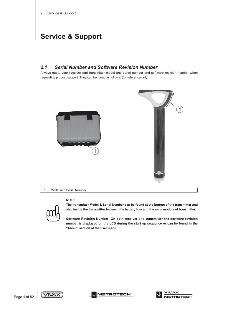
2.1 Serial Number and Software Revision NumberAlways quote your receiver and transmitter model and serial number and software revision number when requesting product support. They can be found as follows: (for reference only)
1 Model and Serial Number
NOTEThe transmitter Model & Serial Number can be found at the bottom of the transmitter and also inside the transmitter between the battery tray and the main module of transmitter.
Software Revision Number: On both receiver and transmitter the software revision number is displayed on the LCD during the start up sequence or can be found in the “About” section of the user menu.
Page 5 of 52
2 Service & Support
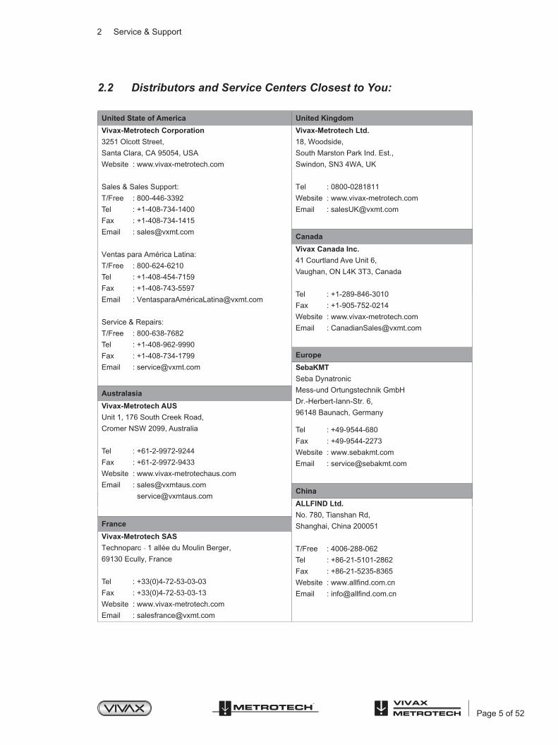
2.2 Distributors and Service Centers Closest to You:
United State of America United Kingdom
Vivax-Metrotech Corporation
3251 Olcott Street,
Santa Clara, CA 95054, USA
Website : www.vivax-metrotech.com
Sales & Sales Support:
T/Free : 800-446-3392
Tel
Tel : 0800-0281811
: +1-408-734-1400
Fax : +1-408-734-1415
Email : [email protected]
Ventas para América Latina:
T/Free : 800-624-6210
Tel : +1-408-454-7159
Fax : +1-408-743-5597
Email : VentasparaAmé[email protected]
Service & Repairs:
T/Free : 800-638-7682
Tel : +1-408-962-9990
Fax : +1-408-734-1799
Email : [email protected]
Vivax-Metrotech Ltd.
18, Woodside,
South Marston Park Ind. Est.,
Swindon, SN3 4WA, UK
Website : www.vivax-metrotech.com
Email : [email protected]
Canada
Vivax Canada Inc.
41 Courtland Ave Unit 6,
Vaughan, ON L4K 3T3, Canada
Tel : +1-289-846-3010
Fax : +1-905-752-0214
Website : www.vivax-metrotech.com
Email : [email protected]
Europe
SebaKMT
Seba Dynatronic
Mess-und Ortungstechnik GmbH
Dr.-Herbert-Iann-Str. 6,
96148 Baunach, Germany
Tel : +49-9544-680
Fax : +49-9544-2273
Website : www.sebakmt.com
Email : [email protected]
Australasia
China
Vivax-Metrotech AUS
Unit 1, 176 South Creek Road,
Cromer NSW 2099, Australia
Tel : +61-2-9972-9244
Fax : +61-2-9972-9433
Website : www.vivax-metrotechaus.com
Email : [email protected]
France
Vivax-Metrotech SAS
Technoparc - 1 allée du Moulin Berger,
69130 Ecully, France
Tel : +33(0)4-72-53-03-03
Fax : +33(0)4-72-53-03-13
Website : www.vivax-metrotech.com
Email : [email protected]
ALLFIND Ltd.
No. 780, Tianshan Rd,
Shanghai, China 200051
T/Free : 4006-288-062
Tel : +86-21-5101-2862
Fax : +86-21-5235-8365
Website : www.allfind.com.cn
Email : [email protected]

Page 6 of 52
3 Introduction
Introduction
3.1 About this HandbookThis handbook is designed to provide the user with a comprehensive understanding of the operation of the vLocDM2 system. The handbook assumes some understanding of Cathodic Protection techniques, it covers the operation of the equipment, the techniques to gather data, storing and retrieving the data in a format that can be analyzed by a competent engineer and a brief explanation of how to use the data to form an understanding of the condition of the pipe network.
3.2 Overview of vLocDM2 SystemThe vLocDM2 (Defect Mapper) has been designed to:
identify the position of coating defects identify shorts to other structures help categorize the faults help plan and prioritize remedial work operate as a long line pipeline locator
The vLocDM2 uses the latest locating and signal processing techniques to plot the current gradient of an industry standard low frequency (3Hz or 4Hz) profiling current. The current is typically applied at CP stations so the disruption of the pipeline can be minimized.
The Loc-150Tx, 150W transmitter (vLocDM2 transmitter) is used to apply a signal current to the anode bed. The pipeline returns the signal via coating faults back to the transmitter. The transmitter is designed to be powered from CP (Cathodic Protection) stations, AC or external batteries, eliminating the need for batteries.
The non-intrusive measuring device, the vLocDM2 receiver, takes measurements along the pipeline and plots the results directly onto the screen of the receiver. There is no need to carry extra logging and display devices. All the data is displayed and logged into the receiver and can be downloaded to a spread sheet or dedicated analysis program.
A +/- 3m accuracy GPS antenna is included with the system. It links to the vLocDM2 receiver via Bluetooth radio link. The GPS enables the user to generate real time current gradient graphs and guides the user back to a point of interest by highlighting the user’s position on the graph. This feature is called the “walk back” feature. The system can also be integrated with high accuracy GPS systems and software packages, for example Trimble and TriGlobal Inc.
Storing the results also has the benefit of facilitating the technique of comparative tests. Comparing the results from previous surveys of the same length of pipe allows the CP engineer to establish trends of coating deterioration.
TheA-framefaultfindingaccessoryisusedtoaccuratelylocatethepositionofafault.Anarrowpointstheusertothepositionofthefaultwhilstquicklyandefficientlygraphingthecharacteristicshapeandmagnitudeoffaultsignalonthereceiversdisplay.Thisensurestheuserminimizesthechancesofmisidentification.
3.3 Planning a SurveySurveys will vary greatly depending on type of terrain, accessibility, condition of pipeline, type of pipeline and coating type.

Page 7 of 52
3 Introduction
The first step of undertaking any survey should be to obtain information about the stretch of pipeline to be surveyed. More work at this stage may well save time and effort later. Obtaining maps showing route information, CPstations,sacrificialanodesandcrossbondingpointswillbeofgreathelp.The transmitter should be capable of transmitting from one CP station to another, so although not absolutely necessary, plan to have the previous and after CP stations disconnected from the stretch of pipeline to be surveyed. Remember that the pipeline is not protected whilst the survey is being undertaken, so unnecessary downtime of CP stations should be avoided.
Choose the survey interval to match the condition of the pipeline. In areas where the coating is particularly poor, a survey interval of as little as 10m may be desirable. However, if the coating is in very good condition and the distance between CP stations is many km, it may be better to choose a survey interval of as much as 200m. Taking measurements at large intervals will enable the surveyor to quickly asses the condition of the pipeline and subsequently identify areas that require further inspection at closer survey intervals or detailed analyses using the A-frame Fault Finder accessory.
WARNINGParts of the pipeline may be crossing road junctions and may even follow the route of roads. Obtaining accurate results from the vLocDM2 requires full concentration from the operator. It is therefore essential that correct traffic management is undertaken at these points to avoid poor results or injury to the operator. Safety should always be the first concern.

Page 8 of 52
4 Transmitter Functions and Operations
Transmitter Functions and Operations
4.1 Transmitter Control Panel
No Control Function1 Power To power on/off the unit2 LCD Display3 Output Current/Active-Standby • Rotate rotary switch to select output current.
• Press and hold to power on or standby4 Frequency/Status • Rotate rotary switch to select frequency.
• Press momentary to view status (refer to status screen in section below)
4.2 Display
Main Screen Status Screen
NOTEPower Limit = The Over Power alarm will be shown on the display when the output power rating of the transmitter is reached. (150W or 50W if 12-28Vdc input is used.)Voltage Limit = The output voltage limit is 100V. If the current cannot be stabilised with a voltage less than 100V it will display an overvoltage alarm.
ON/OFF
LCD Display
Output Current/Standby
Frequency/Status

Page 9 of 52
4 Transmitter Functions and Operations
4.3 Power Supplies and Connections
1 Mains Input2 Mains Input Fuse (5A, 250V)3 12 - 60V DC Input4 Output Fuse (10A, 250V)5 Output Socket
4.4 Connecting to the Pipeline4.4.1 Connecting at a CP (Cathodic Protection) Station
WARNINGConnecting to the CP station involves removing connections from the CP transformer rectifier and should only be performed by authorised personnel. Always make connections before switching on the unit. Switch off before disconnecting the transmitter.
Method:1. Make a note of the CP settings (Output Current and Voltage settings). This is important as the settings must
be checked to ensure they return to the original settings when the connections are re-made.2. SwitchofftheCPtransformerrectifierandallowtheresidualvoltagetodissipate.Thismaybeafewseconds
or a few minutes depending on pipe condition.
3. Disconnect the output wires connecting the CP station to the pipeline and anode bed. If there is an earthed mains socket at the station, connect the transmitter mains power lead to the socket.
CPStation
Mains Socket
DC Output
To Anode
Bed
Standard CP
Station Connections
1
2 3 4
5
-Ve +Ve
Page 10 of 52
4 Transmitter Functions and Operations
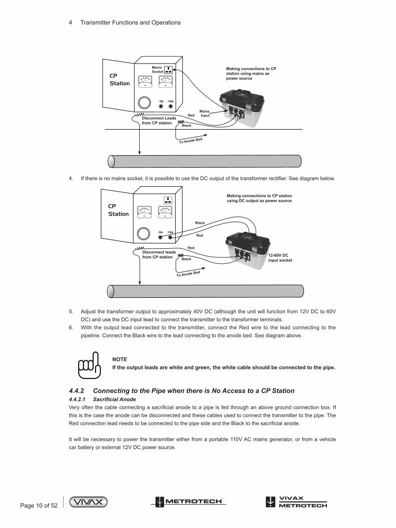
4. Ifthereisnomainssocket,itispossibletousetheDCoutputofthetransformerrectifier.Seediagrambelow.
5. Adjust the transformer output to approximately 40V DC (although the unit will function from 12V DC to 60V DC) and use the DC input lead to connect the transmitter to the transformer terminals.
6. With the output lead connected to the transmitter, connect the Red wire to the lead connecting to the pipeline. Connect the Black wire to the lead connecting to the anode bed. See diagram above.
NOTEIf the output leads are white and green, the white cable should be connected to the pipe.
4.4.2 Connecting to the Pipe when there is No Access to a CP Station4.4.2.1 Sacrificial AnodeVeryoftenthecableconnectingasacrificialanodetoapipeisfedthroughanabovegroundconnectionbox.Ifthis is the case the anode can be disconnected and these cables used to connect the transmitter to the pipe. The RedconnectionleadneedstobeconnectedtothepipesideandtheBlacktothesacrificialanode.
It will be necessary to power the transmitter either from a portable 110V AC mains generator, or from a vehicle car battery or external 12V DC power source.
CPStation
MainsSocket
MainsInput
Disconnect Leadsfrom CP station
To Anode
Bed
Red
Black
Making connections to CPstation using mains aspower source
CPStation
Disconnect leadsfrom CP station
Red
Black
To Anode Bed
Black
Red
12-60V DCinput socket
Making connections to CP stationusing DC output as power source
-Ve +Ve
-Ve +Ve

Page 11 of 52
4 Transmitter Functions and Operations
NOTEIt may not be possible to attain high current from the transmitter, as a sacrificial anode will not provide as good a ground as a system anode bed.
4.4.2.2 Connecting at a Point where Access to the Pipe is PossibleIt is possible to connect the transmitter at any point along the pipe length where an electrical connection is possible. If this is the case a good independent ground will need to be generated by driving a ground stake into the ground a few meters perpendicular to the pipe. The ground needs to be low impedance so the copper ground rod needs to be at least 0.5 meters long. In some cases multiple stakes may be necessary.
A poor ground will result in the transmitter showing the over voltage alarm even at low currents. If this occurs add further ground rods connected in parallel and dampen the surrounding soil.
WARNINGUse a cable locator to ensure the area is clear of services before the rod is driven into the ground.
4.5 Selecting the Correct FrequencyThe available frequency options are:
98Hz, 128Hz, 512Hz, 640Hz, 3Hz/98Hz, 3Hz/128Hz, 4Hz/98Hz 4Hz/128Hz ELF1-3Hz/6Hz/98Hz ELF2-3Hz/6Hz/128Hz ELF3-4Hz/8Hz/98Hz ELF4-4Hz/8Hz/128Hz 3Hz/6Hz/512Hz 3Hz/6Hz/640Hz 4Hz/8Hz/512Hz 4Hz/8Hz/640Hz 512/256Hz 640/320Hz 491Hz
Note that some frequencies may be missing depending on age and software revision of transmitter. Vivax-Metrotechreservetherighttochangethisfrequencylistwithoutnotification.
3Hz/6Hz/98Hz or 3Hz/6Hz/128Hz are the most commonly used frequencies. They provide the low frequency 3Hz component required for current mapping and a low frequency (98Hz or 128Hz depending on local mains frequencies) used to pinpoint the position and is used to determine the pipe depth. The 6Hz enables the locator to calculate the signal direction.
The other frequency options can be used to improve reception in areas of high interference.
4.6 Output Current SelectThere are seven current settings:
100mA 300mA 600mA 1A 2A 3A 4A (When a single locate frequency is selected)

Page 12 of 52
4 Transmitter Functions and Operations
Choosing the correct setting for a particular application depends on many factors but as a general rule “the higher the setting the better”. The higher the current the more stable the readings at long distance and larger currents create larger current changes at faults. However, it will not always be possible or desirable to apply the maximum current.
With the transmitter connected as above, select the 3A position. Wait to see if any alarms are displayed such as over voltage, over power, over temperature. If after 20 seconds no alarms are shown, note the return current reading. This should be 3A+/- 0.1A. Now note the output voltage. This should be less than 100V. The transmitter stabilises the output current by altering the output voltage. The output voltage limit is 100V. If the current cannot be stabilised with a voltage less than 100V it will display an overvoltage alarm. The transmitter is not damaged if this is displayed but the output will not be stabilised. To overcome this, select a lower current setting.
Other causes of over voltage alarms are: Pipeline in very good condition (Small high impedance faults will require higher voltages to achieve the
requested current) Poor anode bed (Poor anode beds will require a high voltage drop across them to create the requested
current) Poor pipe connections
4.7 Alarms4.7.1 Over VoltageOutput exceeds 100V. (Also see Output Current Select)
4.7.2 Over TemperatureTheovertemperaturealarmwillshowsonthedisplaywhenthetemperatureof theoutputamplifierexceedsapredetermined level. At this temperature the unit will shut down and cannot be switched on until the unit has cooled down.
After the unit has been cooled down, it may be necessary to place the unit in a position where the ambient temperature is less such as shaded position. Alternatively select a lower current output.
4.7.3 Over PowerThe Over Power alarm will be shown on the display when the output power rating of the transmitter is reached. The unit will shut down until the output power is reduced.
This can be doing either: Reduce the output current setting Improve the ground and pipe connections. (This may be the case where the ground used is not an anode
bed. For instance where a ground rod is used because access to a CP station is not possible.)

Page 13 of 52
5 Receiver Functions and Operations
Receiver Functions and Operations
5.1 vLocDM2 Receiver Main Display
1 Locate Mode 8 Distance From Last Measurement2 Speaker Status 9 Left/Right Indicator 3 GPS Option Active, bars indicate accuracy 10 Locate Frequency4 Bluetooth Active 11 Signal Strength5 Magnetometer Foot Indicator 12 Pipe Direction Indicator6 Alkaline/Rechargeable Battery Indicator 13 Gain Setting7 Last Record Number 14 Depth to Centre of Pipe
5.2 Magnetometer FootThe device at the bottom of the locator tube is the Magnetometer foot. This device is used to detect the low frequency component (frequencies between 3Hz and 8Hz). These are the vLocDM2 current mapping frequencies. When low frequency mapping is not required, for instance if the equipment is being used for pipeline locating but not defect mapping, the magnetometer foot can be removed.
Removing the magnetometer foot will help reduce the weight of the locator and also change the way the logging is done. The logged frequency will then be the locate frequency selected and graphing will also use this frequency.
5.2.1 Removing the Magnetometer FootIdentify the retaining screw on the side of the antenna tube near the foot. Rotate it anti clockwise for ¼ turn or untilitbecomesstifftorotate.Thisshouldbepossibleusingyourfingers.Onlyuseascrewdriverifthescrewhasbeen over tightened.
Now hold the magnetometer foot and antenna tube. Rotate the magnetometer foot in an anti clockwise direction. The foot should detach itself after a ½ turn.
Nowfittheblankingplatesupplied.
70.2
8kHz
2.24m Log 999104m
74dB

Page 14 of 52
5 Receiver Functions and Operations
IMPORTANTAlways fit the blanking plate when the magnetometer foot is not attached as there are critical contacts within the antenna tube that require protection. Not doing so will invalidate the warranty.
Refittingthefootistheoppositetotheabove.
NOTEWhen setting the retaining screw on the side of the antenna tube, hand tighten only.
5.3 Pushbuttons
Pushbuttons Locate Screen Measure Screen
On/Off On/Off
Change frequency Not active
Short press for measure and long press for user menu Jump back to Locate Screen
Increase gain Save and go to graph
Decrease gain Reject and go to graph and long press to delete log in memory
Change antenna mode Save a record and return to Locate Screen
Pushbuttons Graphing Screen Graph Review
On/Off On/Off
Not active Not active
Highlights active graphing button Deletes highlighted log
Zoom in (scroll right/up) and long press to auto scale horizontal axis
Movescurserright.andalsousedtoconfirmdelete
Zoom out (scroll left/down) and long press to auto scale vertical axis Moves curser left
Return to Locate Screen Returns to Graphing Screen
70.2
8kHz
2.24m Log 999104m
74dB
600mA2.41m
3Hz6Hz104m
10.4mA
V zoom
H zoom H scroll
V scroll SEL Log 213.2mA 19.7mT o Delete
Press

Page 15 of 52
5 Receiver Functions and Operations
Pushbuttons A-frame Screen A-frame Review
On/Off On/Off
Not active Not active
Long press to enter "A-frame Review" mode Deletes highlighted log
Save last reading to graph Movescurserrightandalsousedtoconfirmdelete
Short press rejects last record and long press to clear graph. Moves curser left
Return to Locate Screen Returns to Graphing Screen
Pushbuttons User Menu Screen
On/Off
Not active
Long press to enter "A-frame Review" mode
Save last reading to graph
Short press rejects last record and long press to clear graph.
Select/deselect item
128Hz
15dB
Log 24428dBµV To Delete
Press
OffSpeaker VolumeBacklight HighFrequency Enter
MeterImp/Metric
EnglishLanguage
1 of 3MENU

Page 16 of 52
5 Receiver Functions and Operations
5.4 Connectors
1 Bluetooth Module 6 Charging Socket2 Pushbutton & Display 7 Mini USB Port Data Transfer and Software Upgrade3 Carbon Fiber Reinforced Antenna Assembly 8 Accessories Port4 Accessory & Charging Sockets 9 Model# & Serial#5 USB Memory Stick Data Transfer 10 AA Battery Pack/Rechargeable Battery Pack
5.5 Charging the Receiver BatteriesThe vLocDM2 can be used with either alkaline batteries or it can be supplied with an interchangeable rechargeable battery pack.
Icon A Icon B
When alkaline battery is used, Icon A will appear on the screen. When the rechargeable battery pack is used, Icon B will be displayed. In both cases, the number of bars illuminated within the battery icon indicates the amount of charge remaining.
Rechargeablebatteriesaresuppliedwithamainscharger.Thisisspecifictothebatteries,avoidtheuseofothermanufacturers’ chargers as these may damage the battery pack and may result in overheating of the battery pack.
Tochargetherechargeablebatteries,firstmakesurethepackisinsertedinthereceiverbatterycompartmentascharging is done inside the receiver.
Connect the charger to the charging socket of the receiver. Connect charger to the mains and switch on. The LED indicator on the charger will illuminate red until the batteries are fully charged at which time the LED will change to green.

Page 17 of 52
5 Receiver Functions and Operations
WARNINGRechargeable batteries are supplied with a mains or 12V DC charger. These are specific to the batteries. Only use the charger that is appropriate for the batteries in the product. If in doubt, call Vivax-Metrotech Customer Service. Failure to use the appropriate charger could result in damage to the battery pack, locator and in extreme cases cause fire.
Avoid charging the unit in extreme temperature conditions. (i.e. below 0ºC and above 45ºC)
Although Vivax-Metrotech batteries include all the required safety related features always immediately discontinue use of the charger and battery pack if the battery pack becomes excessively warm. Return both to where they were purchased for investigation.
Always ensure batteries have at least a partial charge if storing for long periods without use.
Dispose of all batteries in accordance with your company procedures and Federal/State and local regulations.
Never dismantle batteries, put them in fire, or get wet.
5.6 Setting User PreferencesThevLocDM2hasmanyfunctionsenablingittobeusedformanyapplicationsandcanbeconfiguredfordifferentmarkets. For instance, it may be desirable for the depth readings to be displayed in imperial measurements or metric. By entering the user menu, it is possible to tailor the vLocDM2 to the requirements of the user.
Enter the user menu by pressing and holding the “i” pushbutton for approximately two seconds until the user menu is displayed.
Select the desired function by pressing the “+” or “-” pushbutton. The active function will be highlighted in red. To change the setting of the selected function, press the “M” pushbutton.
Configurable options are: “Return/M” Pushbutton Note:Speaker Volume Off, Low, Med, HighBacklight Off, Low, HighFrequency Enter Sub menuLanguage EnglishImp/Metric Meter, FeetvLocDM2 Current Live,Static Live - continuous update of vLocDM2 current
Static - One shot display of vLocDM2 current per measurement
Power Sound Normal, Modulated Normal - the pitch remains the same but the volume increase as the signal increasesModulated - the pitch changes as the signal increases
Radio Sound Normal, Modulated
Active Sound Normal, Modulated
Page 18 of 52
5 Receiver Functions and Operations
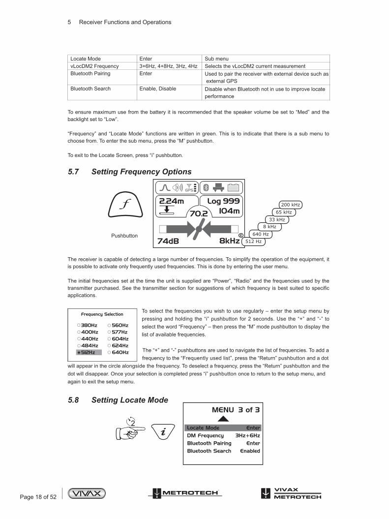
Locate Mode Enter Sub menuvLocDM2 Frequency 3+6Hz, 4+8Hz, 3Hz, 4Hz Selects the vLocDM2 current measurementBluetooth Pairing Enter Used to pair the receiver with external device such as
external GPSBluetooth Search Enable, Disable Disable when Bluetooth not in use to improve locate
performance
To ensure maximum use from the battery it is recommended that the speaker volume be set to “Med” and the backlight set to “Low”.
“Frequency” and “Locate Mode” functions are written in green. This is to indicate that there is a sub menu to choose from. To enter the sub menu, press the “M” pushbutton.
To exit to the Locate Screen, press “i” pushbutton.
5.7 Setting Frequency Options
Pushbutton
The receiver is capable of detecting a large number of frequencies. To simplify the operation of the equipment, it is possible to activate only frequently used frequencies. This is done by entering the user menu.
The initial frequencies set at the time the unit is supplied are “Power”, “Radio” and the frequencies used by the transmitterpurchased.Seethetransmittersectionforsuggestionsofwhichfrequencyisbestsuitedtospecificapplications.
To select the frequencies you wish to use regularly – enter the setup menu by pressing and holding the “i” pushbutton for 2 seconds. Use the “+” and “-” to select the word “Frequency” – then press the “M” mode pushbutton to display the list of available frequencies.
The “+” and “-” pushbuttons are used to navigate the list of frequencies. To add a frequency to the “Frequently used list”, press the “Return” pushbutton and a dot will appear in the circle alongside the frequency. To deselect a frequency, press the “Return” pushbutton and the dot will disappear. Once your selection is completed press “i” pushbutton once to return to the setup menu, and again to exit the setup menu.
5.8 Setting Locate Mode
70.2
8kHz
2.24m Log 999104m
74dB
200 kHz65 kHz
33 kHz8 kHz
640 Hz512 Hz

Page 19 of 52
5 Receiver Functions and Operations
Press and hold the “i” pushbutton to enter the user menu. Use the “+” or “-” pushbutton to navigate to “Locate Mode”. Press “M” pushbutton to select sub menu. The following will be displayed:
Peak Mode:Largest signal over the pipe.
Null Mode:Minimum signal over the pipe includes left/right guidance arrows.
Sonde Mode:Largest signal over the Sonde. Note: Locator is held ACROSS the line of the Sonde. Also note two false signals each side of main signal.
Broad Peak Mode:Increased sensitivity but sharpness reduced. Useful for deep pipes.
Peak with Arrows Mode:Largest signal over the pipe. Includes left/right guidance arrows.
Press the “M” pushbutton to select or deselect a function as indicated by a dot. To exit the user menu, press “i” pushbutton.
Page 20 of 52
6 Using the vLocDM2 Receiver
Using the vLocDM2 Receiver
6.1 Locating a Pipeline
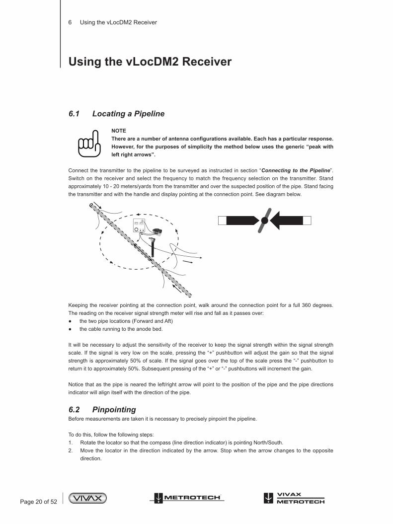
NOTEThere are a number of antenna configurations available. Each has a particular response. However, for the purposes of simplicity the method below uses the generic “peak with left right arrows”.
Connect the transmitter to the pipeline to be surveyed as instructed in section “Connecting to the Pipeline”. Switch on the receiver and select the frequency to match the frequency selection on the transmitter. Stand approximately 10 - 20 meters/yards from the transmitter and over the suspected position of the pipe. Stand facing the transmitter and with the handle and display pointing at the connection point. See diagram below.
Keeping the receiver pointing at the connection point, walk around the connection point for a full 360 degrees. The reading on the receiver signal strength meter will rise and fall as it passes over:
the two pipe locations (Forward and Aft) the cable running to the anode bed.
It will be necessary to adjust the sensitivity of the receiver to keep the signal strength within the signal strength scale. If the signal is very low on the scale, pressing the “+” pushbutton will adjust the gain so that the signal strength is approximately 50% of scale. If the signal goes over the top of the scale press the “-” pushbutton to return it to approximately 50%. Subsequent pressing of the “+” or “-” pushbuttons will increment the gain.
Notice that as the pipe is neared the left/right arrow will point to the position of the pipe and the pipe directions indicator will align itself with the direction of the pipe.
6.2 PinpointingBefore measurements are taken it is necessary to precisely pinpoint the pipeline.
To do this, follow the following steps:1. Rotate the locator so that the compass (line direction indicator) is pointing North/South.2. Move the locator in the direction indicated by the arrow. Stop when the arrow changes to the opposite
direction.

Page 21 of 52
6 Using the vLocDM2 Receiver
3. Adjust the gain by pressing the “+” or “-” pushbuttons so that the bar graph reads approximately 50%.4. Find the largest signal by moving the receiver side to side over the suspected position of the pipeline, see:
(a) Stop at the largest signal. (Note that the left/right arrows will help in this process but the largest bar graph reading gives a truer indication of the actual pipe position.) Now rotate the receiver again until the largest signal is found and the line indicator is pointing at North and South position.
(b) The receiver is now over and the handle is in line with the pipe.
NOTEThe largest signal and current reading will probably be generated by the anode bed cable. Confirm which is which by taking current readings and noting the current direction. The currents on the pipe will be flowing towards the transmitter. The current on the anode cable will be flowing away.
NOTEThe sum of the currents on the two pipe locations should be close to the current displayed on the transmitter. If they are not, it may be that there is a fault at the connection point or that the current flowing on the anode bed cable is interfering with the signal from the pipe. To confirm this take readings a good distance from the connection point. Be aware that the anode bed cable very often runs along the same trench as the pipe for some distance and will affect the readings.
6.3 Taking Depth and Current ReadingsTotakeanymeasurementsitisfirstnecessarytopinpointthepipeasinstructedinthesectionabove“pinpointing”.
Next, hold the receiver on the ground, vertically and with the handle in line with the pipe. Keep the receiver very stationary and press the “i” pushbutton. The display will show the following screen whilst the measurement is made.
50%
Please hold still ...
600mA2.41m
3Hz6Hz104m

Page 22 of 52
6 Using the vLocDM2 Receiver
After approximately 4 seconds the result will be displayed as below.
1 vLocDM2 Mapping Current2 Locate Tone Current3 Depth to Centre of Pipe4 vLocDM2 Frequency5 DistancefromlaststoredmeasurementifGPSfitted6 Save Reading and Enter Graph7 Reject Reading and Enter Graph8 vLocDM2 Signal Direction
Press the “M” pushbutton to save the data and return to “Locate Screen”.
6.4 Storing the Results
NOTEThe vLocDM2 current reading will continue to be updated approximately every second unless Static is chosen in the User setup of “vLocDM2 Current”. This is done so that fluctuations in readings can be identified, allowing the user to wait until stable readings are shown before recording the result.
Pressing the “+” pushbutton whilst the measurement is being displayed will save the results to the next available internal log location, plot the point onto the onboard graph and will also transmit the data using the Bluetooth function.
Pressing the “-” pushbutton whilst the measurement is being displayed does the same as the above. But does not add this point to the record or the graph and does not transmit the data.
Pressing and holding the “-” pushbutton clears the internal log memory. Before the log is cleared a message is displayed as shown in the screen below. Press the “+” pushbutton to delete the log or press the “-” pushbutton to return to the locate screen.
Pressing the “i” pushbutton will exit back to main locate screen without saving the results.
600mA2.41m
3Hz6Hz104m
1.74 A
12
3
4
5
6
7
8
Are you sure you wantto delete all this data log
Press + Key to Delete

Page 23 of 52
6 Using the vLocDM2 Receiver
Pressing the “M” pushbutton whilst the measurement is being displayed will save the results to the next available internal log location, and return to the Locate Screen.
6.5 Graphing the ResultsGraphing the results can be done with or without the GPS function activated. However, if the GPS function is not activated the generated graph will not be scaled with distance but will space the records equally along the x axis. The “walk back feature” will not function unless the GPS feature is activated. To activate the GPS feature, read section 7.1 Compatible GPS and GPS Data Loggers.
The GPS icon on the Locate Screen will illuminate when valid GPS data is being received.
Pressing the “+” pushbutton whilst the measurement is being displayed will automatically update the graph and will also enter the graphing screen.
Graph Screen
Pushbutton Function
Highlight each function in turn. A long press will enter the Review Screen.
Increase zoom or scrolls right/up depending on button highlighted. Long press auto scale horizontal axis.Decrease zoom or scrolls left/down depending on button highlighted. Long press auto scale vertical axis.
Returns to the Locate Screen
To clear the screen, press and hold the “-” pushbutton for 3 seconds. A message will be displayed.
NOTEThe horizontal scale of the graph defaults to equal spaces per record. So the graph assumes equal distance survey points.
IfGPSisactivated,thehorizontalaxisisbasedonthe“asthecrowflies”distancebetweenmeasurementpoints(see Section 7.1 Compatible GPS and GPS Data Loggers).
Therangefinderbarsonthexandyaxisindicatetheportionofgraphbeingviewed.
Pressing and holding the “-” and “+” pushbuttons auto scales the graph in the x and y axis.
If the GPS option is activated, an indicator will be displayed at the present position. This is the “walk back” feature. Use the indicator to identify your position on the graph as you walk back to a point of interest. The indicator will identify the point when it detects that it is within 25m. If the points are closer than 25m, it will show the nearest one. If the distance to any point is greater than 25m, no indicator is shown.
V zoom
H zoom H scroll
V scroll SEL

Page 24 of 52
6 Using the vLocDM2 Receiver
Review Screen
1 Position Indicator Bar2 Record number as indicated by position indicator bar3 vLocDM2 current reading at this point4 Depth to centre of pipe at this point
When in the graphing screen, pressing and holding the “i” pushbutton enters into the Review Screen. This enables the user to scroll through the logged points. A blue vertical line identifies the log position. At each position, the depth and vLocDM2 current readings are shown at the bottom of the graph. To delete a record, pressthe“i”pushbutton.Theunitwillasktheusertoconfirmbypressingthe“+”pushbutton.
To return to the Graph Screen press the “M” pushbutton.
6.6 Using the A-frame Fault FinderThe A-frame is used to pinpoint coating defects along the pipeline. It does this by measuring the voltage in the ground caused by the vLocDM2 signal current entering the pipe at a fault. It is necessary to make a physical/electrical contact with the ground. The A-frame has two spikes to facilitate this. Although the spikes are a few inches long, it is usually only necessary to puncture the ground with the spikes. Inserting them fully is only necessary where the ground conditions are particularly dry or high resistance.
The A-frame should be plugged into the accessory port. The receiver will automatically recognise the A-frame and enterthefaultfindmode.
6.6.1 Fault Finding Method1. Connect the transmitter as previously described. Select either 3Hz/6Hz/98Hz (ELF1) or 3Hz/6Hz/128Hz
(ELF2) depending on mains frequency as previously described.2. Connect the A-frame as above.
6.6.2 Using the A-frameIfthepositionofadefecthasbeenidentifiedbythevLocDM2usingthecurrentgradienttechnique,startanA-framesurvey approximately 20 meters before this point. Place the A-frame in the ground with the A-frame in line, the green pin pointing towards the suspected fault and directly above the pipe. The signal strength will be displayed, if the signal is strong enough an arrow will point forward. Press the “+” pushbutton to save the reading. This will enter the result into the graph. Pressing the “-” pushbutton will delete the last record. The scaling of the graph is automated and may change as points are added.
Log 2132mA 2.41m To Delete
Press

Page 25 of 52
6 Using the vLocDM2 Receiver
A-frame Screen
1 Locate Icon2 Graph3 Fault Direction4 Fault Signal
TIPThe locate icon (1) will still be active whilst using the A-frame and should be used to ensure the A-frame is used directly above the pipe. However, adjustments to sensitivity/mode/frequency can only be made when in the Locate Screen. It is possible to jump to the Locate Screen by pressing the “Return” pushbutton. Make the desired adjustments in the Locate Screen and then jump back to the A-frame Screen by again pressing the “Return” pushbutton.
Continue walking in the direction of the arrow placing the A-frame in the ground at approximately one meter intervals saving the results as you go. The graph will rise as the defect is approached and then fall at the defect. Continuing past the defect will create a similar but reversed effect. A typical defect “signature” is shown below.
NOTEIf GPS is not activated, the horizontal intervals are assumed to be equal. If a GPS option is activated, the intervals are still shown as equal on the graph but the internal data log stores the GPS coordinates with the GPS data. This is because the accuracy of the GPS function tends to be less accurate than is what is required for A-frame fault finding.
To delete the log, you can press and hold the “-” pushbutton. A message will be displayed as shown in the screen below.
128Hz
15dB1
3
4
2

Page 26 of 52
6 Using the vLocDM2 Receiver
Pressthe“+”pushbuttontoconfirmtodeletethelog,orpress“-”pushbuttontoreturntothegraph.
At the null point, the arrows will reverse; this is the location of the defect. Repeating the procedure across the pipeline will help pinpoint the defect in the other plane. See diagram below.
Sometimes it is not possible to gain access to the pipe position. If this is the case walking along the route of the pipe a few meters to one side can very often produce good results. This procedure is also useful where the pipe runs under “blacktop” which acts as an insulator preventing the A-frame from making a good connection to ground.
6.6.3 Using the A-frame where there are Many Defects Such As Porous CoatingPoorly coated pipelines such as old bitchumin coating, may create a confusing result when as multiple defects willinterferewitheachother.Toovercomethis,itissometimesbeneficialtoadoptadifferentapproach.
This alternative approach involves using the A-frame perpendicular and to one side of the pipeline. See diagram below:
Are you sure you wantto delete all this data log
Press + Key to Delete

Page 27 of 52
6 Using the vLocDM2 Receiver
Note the depth of the pipeline. Move approximately this distance to one side. Keep the orientation as above, walk along the section of pipeline taking readings at regular intervals. A typical result is shown below with the main defect being the largest reading. Note that the arrow will always point to the pipe, ie will not reverse unless the signal reduces to a level that cannot be processed correctly.
A-frame Review Screen
1 Position Indicator Bar2 Record number at this point3 A-frame fault intensity reading at this point4 A-frame fault direction at this point
When in the graphing screen, pressing and holding the “i” pushbutton enters into the Review Screen. This enablestheusertoscrollthroughtheloggedpoints.Ablueverticallineidentifiesthelogposition.Ateachpositionthe A-frame readings are shown at the bottom of the graph. To delete a record, press the “i” pushbutton. The unit willasktheusertoconfirmbypressingthe“+”pushbutton.
To return to the Graph Screen press the “M” pushbutton.
Log 24428dBµV To Delete
Press

Page 28 of 52
7 Using an External GPS Data Logger
Using an External GPS Data Logger
7.1 Compatible GPS and GPS Data LoggersThe vLocDM2 is compatible with most Bluetooth operated systems. However, the system has been tried and tested using the standalone GPS system “M-1200 Wireless GPS Receiver” from “HOLUX” (Supplied as standard) and also the “Trimble ProXT” system. Vivax-Metrotech reserve the right to alter or add to this list.
7.2 Bluetooth
ThevLocDM2isfittedwithaBluetoothcommunicationsaccessory.If,foranyreasontheBluetoothmoduleneedsto be replaced follow the instructions below.
7.2.1 Fitting the Bluetooth Module1. Ensure the unit is switched off.2. Use a small cross head screw driver to remove the two screws retaining the Bluetooth cover. This is found
at the back of the handle near the battery compartment.3. Remove the cover by sliding it away from the handle.4. Take the Bluetooth module and carefully slide it into the position the cover was occupying. 5. Replace the two cross head screws.6. Switch on the unit and after a few seconds a grey, Bluetooth icon should appear showing that the module is
fitted.7. If a red line is shown through the icon, this indicates that the Bluetooth module is not enabled. Bluetooth
enable is located in the user menu which is accessed using a long press of the “i” button. 8. The Bluetooth can communicate with external devices that are also Bluetooth enabled. There are many
Bluetooth enabled GPS devices but Vivax-Metrotech offer the Holux GPS as a suitable solution for those requiring mapping to accuracies better than 5m. For those requiring accuracies better than this, for instance submeter accuracy, the customer should contact a GPS supplier of their choice. However, as a recommendation, one such device that delivers submeter accuracy is the Trimble ProXT.
7.2.2 Bluetooth PairingWhenusingtheBluetoothtoconnecttotheexternaldevicethesystemmustfirstbe“Paired”.
1. Switches on the Bluetooth device.2. Then switch on the vLoc receiver and enter the menu by a prolonged press of the “i” pushbutton.3. Scroll down the options using the “+”/“-” pushbuttons until “Bluetooth pairing” is highlighted.4. Press the “Return” pushbutton. 5. The unit will search for available Bluetooth devices. After a few seconds, a list of devices will be shown.
Highlight the appropriate device using “+”/“-” pushbuttons and then press the “Return” pushbutton to select the device.
The system is now paired with this device. It will not be necessary to pair again unless the unit is paired with a different device. That is to say the locator can only be paired with one device at a time.

Page 29 of 52
7 Using an External GPS Data Logger
NOTEThe internal Bluetooth device may affect the operation of the "Radio Mode". When using "Radio Mode" disable the internal Bluetooth device by entering the menu (long press “i") and selecting disable "Bluetooth Search".
7.3 Transferring Data from the vLocDM2 to a ComputerTo transfer data from the vLocDM2 to a computer requires the use of a simple free of charge software package MyLocator2. It can be downloaded from the Vivax-Metrotech web site www.vivax-metrotech.com.
7.4 MyLocator2MyLocator2configurationtoolisasoftwarepackagethatenablestheoperatortoconfigurethevLocseries2oflocators. The software is compatible with Window XP, Vista and 7. To install, use the link on the Vivax-metrotech website and follow the installation instructions. A MyLocator2 shortcut icon will appear on your desktop.
MyLocator2 is under continual development so the following is a guide to its operation but there may be subtle changes to screens etc. However, the guide should still give sufficient information for the user to navigate MyLocator2.
7.4.1 Launch the ApplicationTo launch MyLocator2, double click on the MyLocator2 shortcut icon. If the host computer is connected to the web, it will check to see if MyLocator2 is the latest version. If it is not, it will ask if you wish to install the latest version. Follow the instructions if you wish to install the new version.
MyLocator2 can be operated on different levels. Each level enables different features and functionality. Some levels require a dongle to operate. Dongles are available from Vivax-Metrotech.
In its basic form it allows the operator to: Check the software revision number and download the latest version. This feature is useful where software
changes have been made to enhance existing features and to install new free of charge features as they become available.
Addingflashscreens:TheusercanaddpicturesorcompanyLogo’sofhischoicetothestartupscreen. Transfer data from the receiver data log to a host computer.
The basic operational screen is displayed below.

Page 30 of 52
7 Using an External GPS Data Logger
Connect the vLocDM2 Receiver to the PC using a USB to Mini USB cable. The PC should recognize the vLocDM2 and the display will now change to the below or similar.
If connected to the web, MyLocator2 will check at this stage to see if there is a newer version of MyLocator2 or locator sw is available. If it is and you wish to update either software follow the instructions.
The configuration of the locator can be saved at any time as described below in section 7.4.8. However, MyLocator2willoccasionallyprompttheusertosaveaconfiguration.Itisnotnecessarytosaveaconfigurationatthesetimesunlesstheuserwillfindtheconfigurationusefulatalaterdate.
It will now be possible to perform the 2 operations in the tabs shown.
7.4.2 Splash Screen1. ClicktheSplashScreentab.Clickonthe“Open”button.Browseyourcomputertofindthepicturethat is
intended to be the splash screen.2. The software will accept the following formats: JPG, BMP, GIF, PNG, ICO.3. Selectthefileandopen.Thescreenbelowshouldnowalsocontainarepresentationofthepicture.4. Press“Download”totransferthefiletothevLocor“Clear”toremovethefile.5. Clicking on “Scale to LCD” will alter the aspect ratio of the picture to fully fill the screen. Leave this
unchecked if no scaling is required. Check the “Centre” button to centre the graphic on the screen.

Page 31 of 52
7 Using an External GPS Data Logger
6. Textcanalsobeaddedtotheflashscreen.7. Usethe“Text”,“BGColor”(Backgroundcolor)and“Font”buttonstoaddtexttothestartupflashscreen.
7.4.3 Software Update1. With the locator switched on and connected to the computer, click on the “Software Update” tab.2. A screen similar to the one below should be shown.
3. If connected to the Web, MyLocator2 will indicate if a newer version of software is available. If you wish to download it select “Yes” in the dialogue box. (This action will also be performed automatically when the unit is connected to MyLocator2.)
4. The progress bars below will start to activate showing the progress of the software installation. When it is complete a message “software download complete” will be shown both on the computer and locator screen.
5. Note that the new software will not be active until the unit has been switched off and on again.
7.4.4 Transferring DataTransferring data from the receiver data log to the host computer.1. Click in the “Import Data” tab. A screen similar to the below should be shown.
Time/Date/Distance settings can be selected on the right hand side.
Page 32 of 52
7 Using an External GPS Data Logger
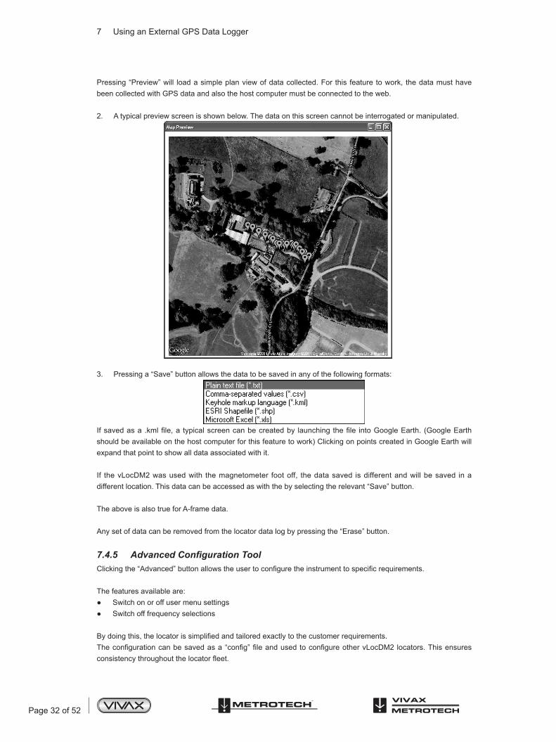
Pressing “Preview” will load a simple plan view of data collected. For this feature to work, the data must have been collected with GPS data and also the host computer must be connected to the web.
2. A typical preview screen is shown below. The data on this screen cannot be interrogated or manipulated.
3. Pressing a “Save” button allows the data to be saved in any of the following formats:
Ifsavedasa.kmlfile,a typicalscreencanbecreatedby launchingthefile intoGoogleEarth.(GoogleEarthshould be available on the host computer for this feature to work) Clicking on points created in Google Earth will expand that point to show all data associated with it.
If the vLocDM2 was used with the magnetometer foot off, the data saved is different and will be saved in a different location. This data can be accessed as with the by selecting the relevant “Save” button.
The above is also true for A-frame data.
Any set of data can be removed from the locator data log by pressing the “Erase” button.
7.4.5 Advanced Configuration ToolClickingthe“Advanced”buttonallowstheusertoconfiguretheinstrumenttospecificrequirements.
The features available are: Switch on or off user menu settings Switch off frequency selections
Bydoingthis,thelocatorissimplifiedandtailoredexactlytothecustomerrequirements.Theconfigurationcanbesavedasa“config”fileandusedtoconfigureothervLocDM2locators.Thisensuresconsistencythroughoutthelocatorfleet.

Page 33 of 52
7 Using an External GPS Data Logger
7.4.6 Switch On/Off User Menu Settings1. With the locator switched on and connected to the host computer click on the “Menu Settings” tab.2. A screen similar to the one below should be shown. If not, click on the “Get Cfg” icon on the top bar. This will
loadtheconfigurationoftheconnectedlocatortothehostcomputer.
3. Check the boxes that are required to be made available.4. Click on the pull down menu and select the settings required.5. The boxes on the right that contain an “+” indicate that there is a sub menu attached to this button. Click on
it to make the sub menu visible.6. Clickingonthe“SendCfg”iconwillsendtheconfigurationtothelocator.
7.4.7 Switching On/Off Frequency Selections1. Click on the “Frequencies” tab. A screen similar to the one below should be shown.
2. Each row is color coded: Grey indicates that frequency is not selected for either the menu or the frequency key. White indicates that the frequency will be active in the locator menu but has not been selected to show
on the frequency key. (Note that it is still possible to make this frequency available on the locator by selecting it in the locator frequency menu.

Page 34 of 52
7 Using an External GPS Data Logger
Green indicates that the frequency will be available both in the locator menu and frequency select key. Blue shows active line.
3. Make the selections required.4. Clickingonthe“SendCfg”iconwillsendtheconfigurationtothelocator.
7.4.8 Saving a ConfigurationHavingcreatedaconfigurationitispossibletosavethisforfutureuse.To save a configuration:1. Click on the “Save Cfg” icon.2. Browsetoadesiredfilelocation.3. Createanameforthatfile,theextensionwillbe:filename.vmcfg.4. Press “Save” in the window.
To retrieve the file:1. Clickonthe“OpenCfg”iconandbrowsetoselectthedesiredfile.2. Click on “open” in the window.3. ThefilewillpopulatetheMyLocator2screenautomaticallywiththesettingsfromtheconfigurationfile.
7.4.9 Configuration Lock DongleA Configuration Lock dongle is available that allows “lockout” of features and functions so that operators are forced to use particular settings. The dongle is also used to unlock these features.
To activate the dongle, plug it into any USB socket on the host computer.With the dongle active, the MyLocator2 screen will look similar to the picture below.
Note the padlocks on the three tabs, Menu Settings, Frequencies and Splash Screen.
Whena locator isconfiguredwith these locksactivated, themenuandfrequencyoptions in the locatorsusermenu will not appear, stopping the user from altering the settings downloaded to the locator by the Dongle activated MyLocator2 facility.
To activate the padlocks simply double click on the desired tab. The features can only be re activated by connecting to a host computer with MyLocator2 which has been dongle activated. Double click on the padlocks as before to unlock them and download the changes to the locator.

Page 35 of 52
7 Using an External GPS Data Logger
Example use of the Dongle Lock:Supposing the Dongle User wishes to force the user to only use 128Hz. The operation would be:1. Connect the locator to the host computer and switch on. Launch MyLocator2.2. Clickonthe“GetCfg”.ThiswillpopulateMyLocator2withtheLocatorsconfiguration.3. Click on the “Frequency” tab.4. Uncheck all frequencies except 128Hz.5. Check both boxes associated with 128Hz as below.6. Double click on the “Frequency” tab to lock the padlock.
7. Now click on the “Send Cfg” icon to send it to the locator8. Toactivatethenewconfigurationswitchthelocatoroffandon.
7.4.10 Icon SummaryIcon Function
Opensapreviouslysavedconfiguration.
Savesaconfigurationcreatedbytheoperatortoafileofyourchoice.
Either“Send”(saves)configurationtoalocatoror“Get”(copy)aconfigurationfromalocator.
“Clears”aconfigurationcreatedontheconfigurationtool.

Page 36 of 52
8 Interpreting Results
Interpreting Results
8.1 IntroductionUsing the vLocDM2 system can quickly and efficiently assess the general coating of a pipeline network. It can help identify defects and possible shorts to other structures. It can be used as a tool to prioritise and plan work on the network. However, unless care is taken when interpreting the results, misinterpretation can lead to unnecessary work and expenses.
8.2 Sources of ErrorMosterrorsareeithercausedbycarelessnessintakingreadingsorbyinterference(ordistortedsignalfield).
8.2.1 Operator ErrorIt is essential that care is taken when taking readings. Great care should be taken to pinpoint the position of the pipeline before a measurement is taken. The locator must be aligned and held vertically. The measurements are only as good as the care taken to obtain them.
Thesensorsusedtodetect the lowfrequencyvLocDM2profilingsignalareverysensitive to lowfrequencies.Movingtheinstrumentwhilsttheunitiscalculatingtheinformationwillcausethestrongearth’smagneticfieldtoinduce an interfering signal into the sensors resulting in errors. The vLocDM2 must be kept absolutely still whilst it is taking measurements.
8.2.2 Interference (Distorted Fields)ThevLocDM2evaluatestheelectromagneticfieldsignalradiatingfromapipelinetodeterminethe informationrequired.Itassumedthatthefieldisradiatingfromthepipeinauniformway.Unfortunatelythefieldispronetobeing distorted and this can lead to errors.
8.2.2.1 Source of Interference (Distorted Fields)Therearemanysourcesoffielddistortionbutthishandbooklistssomeofthemorecommonsourcesofdistortion:
Changes in Pipeline Direction Adjacent Pipes or Cables Cross Bonding Passing Vehicles Pipe Sleeving Changes in Pipeline Direction
Whenever there is a change in pipeline direction there will be some field distortion. See diagram below. The sharper the change, the bigger the distortion. Avoid taking measurements at these points.

Page 37 of 52
8 Interpreting Results
Adjacent Pipes or CablesAdjacent pipelines or cables very often have a signal induced onto them by capacitance or inductive effects. These signals will interfere with the signal on the target pipe and will cause distortion. See diagram below.
Cross BondingPipes can often be cross bonded. This is a deliberate action designed to reduce the number of CP stations and to limit the effects of stray currents.
Ifthepipesarelaidinthesamepathandareincloseproximitythecurrentsflowingonthetwopipeswillinterferewith each other and cause interference. For best results the cross bonding should be disconnected for duration of the survey.
Passing VehiclesThe sensing devices used to detect the 3Hz vLocDM2 profiling signal are very sensitive to low frequencies. Vehicles passing very close to the receiver will disturb the earth’s magnetic field and cause distortion of the received signal. Try to take measurements when there is a gap in passing vehicles.
Inareaswheretrafficispassing,waituntilthreeconstantconsecutivereadingshavebeenshownbeforesavingresult.
Pipe SleevingIt is common practice to insert a pipe in a protective steel sleeve. This may distort the signal and cause errors. Take readings before and after the sleeve. If they are the same, the pipeline is well insulated through the sleeve. Sleeves are very often used at road crossings.
8.2.2.2 Checking for Distorted FieldsChecktosee if thesignal isbeingdistortedbyotherradiatedfields.Locatethepipe,first in the“Peak”mode,and then in the “Null” mode. The two locates should indicate that the pipe is in the same place. If they do not, the signalfieldisdistorted.
If the antenna mode, “Peak with arrows”, is selected the same can be achieved without having to switch between modes.Todothis,firstfindthepositionof thepipeusing the largestbargraphreadingasabove.Then,findthe position as indicated by the arrows. The arrows will indicate the same position as the null response of the bargraph.Hence,ifthearrowsandbargraphindicatethesamepositionthereisunlikelytobesignificantfielddistortion.
1 Null Position2 True Position3 Peak Position

Page 38 of 52
8 Interpreting Results
8.3 Viewing DataUpload the data from the vLocDM2 receiver as described previously in section Upload Data FilesFiles can be saved in the following formats:.xl, .txt, .kml, .shp.
8.3.1 Viewing .xl FilesOpenanExcelspreadsheetandopenthedesiredfile.Somethingsimilartothescreenbelowwillbedisplayed.The data is now in the form of an Excel spreadsheet and can be minupilated to create suitable graphs.
Intheexampleabove,thedistancecolumnisfilledautomatically,astheGPSoptionwasusedwhendatawascollected. If GPS was not used, the distance between measurements will have to be inserted manually.
It is now possible to generate a graph. Graphs are most commonly done as vLocDM2 Current against Distance.
Highlight the Accumulated Distance records and then press the “Ctrl” key whilst highlighting the vLocDM2 Current column.
From the “Insert” tab, select “Scatter Plot”. And from the menu, select the desired graph. The graph will then be generated as below.

Page 39 of 52
8 Interpreting Results
The graph is drawn with a linear current x axis. If a logerithmic scale is required, right click on the x axis and select logerithmic from the options as below

Page 40 of 52
8 Interpreting Results
8.3.2 Viewing .kml FilesToview.kmlfilesitisnecessarytohaveGoogleEarthinstalledonthehostcomputer.IfnotalreadydonevisittheGoogle Earth Web and install the latest version.
Tolauncha.kmlfile,doubleclickontheselectedfile.IfconnectedtothewebandifGoogleEarthapplicationisinstalled on the host computer, Google Earth will automatically launch and will zoom to the site location. Pins will indicate survey points. Clicking on a point will show measurement details for that point. (Note these details are continually under review and may change without notice).The map is a typical representation but note that this feature is under continual development and may change to include new features without notice.
8.4 Interpreting GraphsThere are two types of graphs that can be plotted. These can either be plotted.1. Linear2. Logarithmic
In either case, it is important to look at the trend of the graph rather than individual points. This is because the signalsradiatingfromapipecanbeaffectedbymanyexternalinfluencessuchas:
passing cars ground currents from stray currents ground currents from the transmitter slight movements of the receiver
This is just a few examples, the list is probably endless.The intention is to identify changes in current which signify a defect. So if we were to look at a small section of
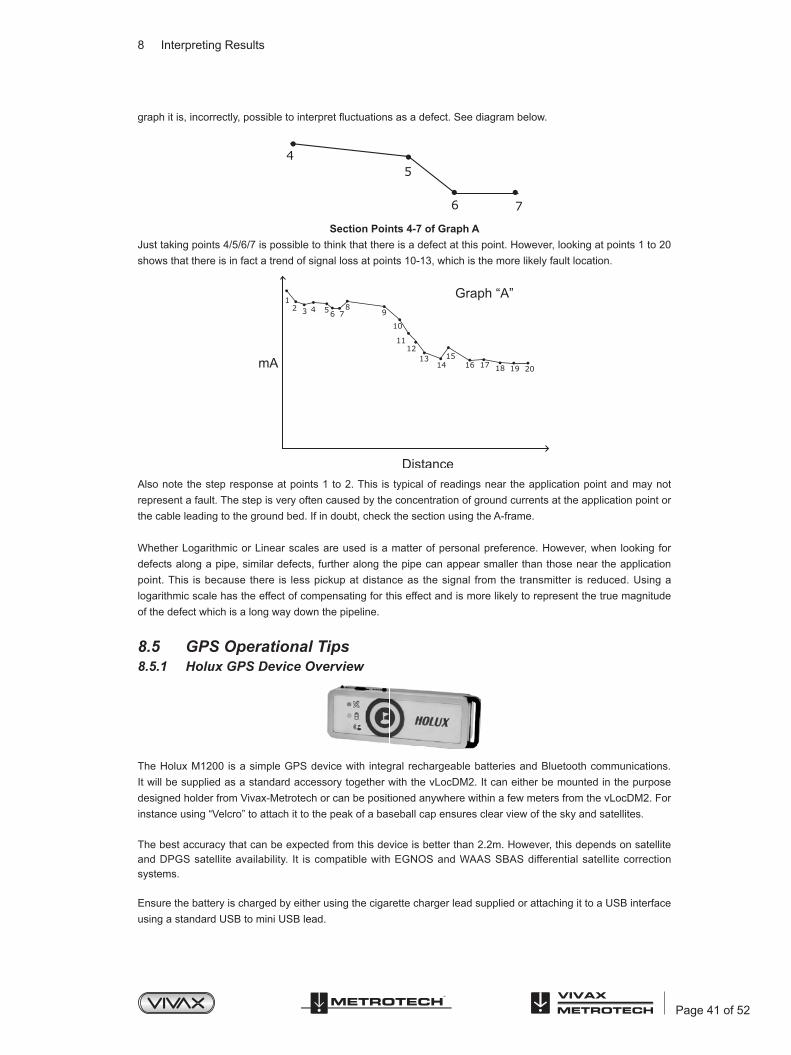
Page 41 of 52
8 Interpreting Results
graphitis,incorrectly,possibletointerpretfluctuationsasadefect.Seediagrambelow.
Section Points 4-7 of Graph AJust taking points 4/5/6/7 is possible to think that there is a defect at this point. However, looking at points 1 to 20 shows that there is in fact a trend of signal loss at points 10-13, which is the more likely fault location.
Also note the step response at points 1 to 2. This is typical of readings near the application point and may not represent a fault. The step is very often caused by the concentration of ground currents at the application point or the cable leading to the ground bed. If in doubt, check the section using the A-frame.
Whether Logarithmic or Linear scales are used is a matter of personal preference. However, when looking for defects along a pipe, similar defects, further along the pipe can appear smaller than those near the application point. This is because there is less pickup at distance as the signal from the transmitter is reduced. Using a logarithmic scale has the effect of compensating for this effect and is more likely to represent the true magnitude of the defect which is a long way down the pipeline.
8.5 GPS Operational Tips8.5.1 Holux GPS Device Overview
The Holux M1200 is a simple GPS device with integral rechargeable batteries and Bluetooth communications. It will be supplied as a standard accessory together with the vLocDM2. It can either be mounted in the purpose designed holder from Vivax-Metrotech or can be positioned anywhere within a few meters from the vLocDM2. For instance using “Velcro” to attach it to the peak of a baseball cap ensures clear view of the sky and satellites.
The best accuracy that can be expected from this device is better than 2.2m. However, this depends on satellite and DPGS satellite availability. It is compatible with EGNOS and WAAS SBAS differential satellite correction systems.
Ensure the battery is charged by either using the cigarette charger lead supplied or attaching it to a USB interface using a standard USB to mini USB lead.
45
6 7

Page 42 of 52
8 Interpreting Results
To switch on the M1200 position the slider switch, located on the side of the device, to the on position. The Bluetoothiconwillflashrapidly(approxeveryhalfsecond).Thisindicatesthatitissearchingforadevicetopairwith.WhentheHoluxispairedwithadevicetheflashingwillchangetoaslowerrate.
The GPS icon will be continuously illuminated indicating that GPS lock is not achieved. When the GPS icon starts toflashGPSlockisachieved.
TIPFor best results allow the GPS indicator to flash at least 15 minutes before commencing a survey.
8.5.2 Pairing with the vLocDM2 Receiver1. Switch on the M1200 and ensure it is within a couple of meters of the receiver.2. Pairing the M1200 with the receiver is achieved through the setup menu. To enter the setup menu press and
hold the “i” pushbutton. 3. Press the “+” pushbutton to scroll to “Bluetooth Pairing” and press the ”M” pushbutton. The receiver will
begin to search for available devices. At the end of the search, a list will be displayed which should include “HOLUX_M-1200” Use the “+” and “–” pushbuttons to highlight this device and press the “M” pushbutton.
4. The vLocDM2 will automatically return to the locate screen. Within 10 seconds the Bluetooth icon will change from grey to blue. This indicates that pairing is successful.
TIPWhen not using the Bluetooth function switch off the Bluetooth search function by entering the user menu and deselecting “Bluetooth Search”. This will save battery life and prevent interference from the Bluetooth search activity, in the Radio mode.
When the Bluetooth search function is deactivated a red line will appear through the Bluetooth icon in the locate screen.
5. Next to the GPS icon is the signal quality bar graph. This will not appear until a valid GPS signal is detected.6. The bar graph has 4 levels. For best results, allow a few minutes after the bar graph has started before
commencing the survey. The accuracy will improve with more bars illuminated.
TIPTo view Google files it is first necessary to install the Google earth application to your computer. This is a free application which can be found at http://www.google.com/earth/download/ge/agree.html
8.5.3 Trimble ProXT/XH
For those wishing to work with accuracies better than 1 meter, the Trimble ProXT/XH provides a simple and cost effective solution. The ProXT operates in a very similar way to the Holux in that it has two LEDs indicating that there is Bluetooth lock and another for GPS lock. Bluetooth pairing is one in the same way as the Holux described above. Data gathering is exactly the same as with the Holux described above.

Page 43 of 52
8 Interpreting Results
8.5.3.1 Trimble ProXT/XH Setting up ProcedureTheProXTcanalsobeconfiguredfordifferentapplicationssothefirsttimeitisuseditshouldbeconfiguredtooperate with the vLocDM2 receiver.
Install to your computer the Trimble GPS Controller software. This is a free application and can be found at http://www.trimble.com/pathfinderproxt_ts.asp?Nav=Collection-32840.
Connect the Trimble ProXT to your computer either by setting up a Bluetooth connection or by using the RS232 lead supplied.
Launch the application and switch on the GPS. When connection is achieved a little satellite icon will appear in the middle of the top bar.
1. From “Skyplot” select “Setup”.
2. Now select “GPS Settings”.
3. Select COM1 and set the parameters as below and then press OK.

Page 44 of 52
8 Interpreting Results
4. Now select the spanner on the “NMEA Output” line.
5. Set the following parameters:
6. Press OK to save parameters to the GPS.7. These parameters are suggested values. Experienced users may decide to alter them to suit the particular
requirements of an application.8. Pairing with the vLocDM2 is similar to the Holux described previously. Data gathering is also similar to the
Holux procedure.

Page 45 of 52
9 Care and Maintenance
Care and Maintenance
9.1 CleaningCleaning can be done with a cloth dampened with warm soapy water. Do not use scouring pads on the casing or display surfaces as this will scratch the device. Do not submerge or pour water over the receiver or transmitter.
Always dry the equipment before storing.
9.2 Checking FunctionalityThe vLocDM2 system can be checked using a simple test procedure. It requires an area clear of pipes and cables and free from metallic structures such as metal tanks, metal railings and reinforced concrete.
A 40m square loop of wire needs to be set out on the ground with a non metallic structure placed at 1m above the cable and at the midpoint of one of the straight sections. See diagram below.
Method:1. Set the transmitter to 128Hz (98Hz if in a 60Hz environment)/3Hz/6Hz, set the current to 100mA.2. Set the locator to receive 128Hz (or 98Hz). Position the locator on the non-metallic structure and carefully
align so that it is above and in line with the cable. Set the gain of the locator to read approximately 50%. Check that the line indicator is pointing “North/South”, if it is not there could be an interfering signal or you may be too near to a bend of the loop.
3. Hold the locator very still and press the “i” pushbutton. After a few seconds, a result will be displayed on the instrument.
4. Check that the arrow is pointing back towards the white (or red) connection lead.5. Check the vLocDM2 current reading is 100mA +/-10mA (10%).6. Check the depth is 1m +/-7cm.7. Repeat for each of the current settings of the transmitter.8. Successfulcompletionofthesetestsconfirmsthatboththereceiverandtransmitterarefunctional.

10 Data Sheet
Page 46 of 52
Data Sheet
10.1 vLocDM2 Receiver Data SheetvLocDM2 Typical Applications
Item ParameterDescription Pipeline defect mapper receiver and transmitter
Uses - Locating and pinpointing coating defects on buried pipelines - ProfilingtheCPcurrentdistributiononapipelinenetwork - Identificationofshortcircuitsfrompipelinestootherstructures - Long distance pipeline location - Transmitting active signals for the location of coating defects on buried
pipes
vLocDM2 Receiver AssemblyItem Parameter
Construction - Carbonfiberreinforcedantennatube - High impact thermoplastic (ABS) injection molded housing - Removable ABS foot molding containing magnetometer
Weight 6lbs (2.7kg)Dimension 11.7in(L) x 5.5in(W) x 30in(H) (262mm x 122mm x 750mm)
Display Type Sharp TFT LCD ¼ VGA color display, 3.52in (89mm)Receiver Antennas 2 x Peak antennas, 1 x null antenna, 1 x compass antenna, 1 x
magnetometer Batteries - Rechargeable Lithium-ion batteries with 100-240V AC mains charger.
- Replaceable (6 x standard alkaline AA batteries) batteries can be used when required
Battery Life - Alkaline – typically 8 hours intermittent use at 70ºF (21ºC) - Lithium-ion – typically 24 hours intermittent use at 70ºF (21ºC) - Re-charging cycles approx. 500 times life cycle
(Battery life varies with temperature)Bluetooth - Plug and Play custom Bluetooth interface
External Connectors
- 1 x Socket for USB accessories & analogue accessories - 1 x Mini USB socket for data transfer / programming - 1 x Socket for battery charger - 1 x Standard USB (Memory stick) socket for data transfer (Future
feature)Approvals - Complies with European standard CE (Directive 99/5/EC)
EN 55011 EN 61000-4-2: A1 & A2 EN 61000-4-3 EN 61000-4-8: A1 ETSI EN 300 330-2 ETSI EN 301 489-1 ETSI EN 301 489-3
- Complies with FCC Rules Part 15 CFR 47 part 2 CFR 47 Part 15

10 Data Sheet
Page 47 of 52
Standard Accessories - Bluetooth Module - Holux GPS (Bluetooth connectivity) - Transmitter: Loc-150Tx and connection leads - A-frame - USB data cable - 100-240V AC mains receiver charger (for Lithium Ion battery) - Soft carry bag (inclusive of accessories bag) - User handbook - Desktop application (desktop programming data management)
Userselectableconfigurationmanagement Replicationofuserconfiguration
Accessories (Optional) - Remote Antenna USB - Sondes (waterproof self-contained transmitters for use in pipes & ducts)
D18-33-SR44 - 0.75in(Dia.) x 3.1in(L) (18mm x 80mm), 33 kHz, range 15ft (4.5m), 2 x button cell batteries
D38-33-AA – 1.5in(Dia.) x 4.1in(L) (38mm x 105mm), 33 kHz, range 16.3ft (5m), 1 x AA battery
D38-09-AA – 1.5in(Dia.) x 4.1in(L) (38mm x 105mm), 9.82 kHz, range 16.3ft (5m), 1 x AA battery
D38-83-AA – 1.5in(Dia.) x 4.1in(L) (38mm x 105mm), 83 kHz, range 16.3ft (5m), 1 x AA battery
D64-33-6LR61 – 2.5in(Dia.) x 7.3in(L) (64mm x 186mm), 33 kHz, range 26ft (8m), 1 x 6LR61 battery
D64-09-6LR61 – 2.5in(Dia.) x 7.3in(L) (64mm x 186mm), 9.82 kHz, range 26ft (8m), 1 x 6LR61 battery
D64-83-6LR61 – 2.5in(Dia.) x 7.3in(L) (64mm x 186mm), 83 kHz, range 26ft (8m), 1 x 6LR61 battery
D23F-512-AA / D23F-640-AA – 1in(Dia.) x 18in(L) (23mm x 456mm), 512Hz or 640Hz, range 20ft (7m),flexibleSondein3sections for use in cast iron pipes as well as non metallic pipes, 1 x AA battery
vLocDM2 Receiver OperationalItem Parameter
Information Displayed - Signal strength - moving bar graph & numeric value - Mode indication (“Peak”, “Null”, “Sonde”, and “Peak with proportional
left/right arrows” location) - Proportional left/right indication - Compass (line direction indicator) - vLocDM2 Signal Direction - Plug and Play automatic recognition of accessories - Accessoryspecificcustomscreen - Line location - Depth & current measurement - Sonde location - Depth measurement - Measurement of vLocDM2 mapping current - Gain level (in dB) - Battery condition - Speaker volume - Operating frequency - Bluetooth and GPS status - Configurationmenu&submenus - Start up screen – product and USB accessories software revision - Customerdefinablestartupscreen

10 Data Sheet
Page 48 of 52
Item ParameterEnhanced Features - Removable foot
- Reduced size and weight with enhanced ergonomic design
- Distance from last reading (when GPS facility activated) - Log number - Real time vLocDM2 mapping and on screen graphing (walk back
feature) - “Walk back feature” giving physical position on graph allowing the user
to walk back to a point of interest. - Real time A-frame fault mapping and on screen graphing
Configuration Intuitive setup menu enables user to configure vLocDM2 receiver or use MyLocator2applicationtoconfigurevLocDM2receiver:1. Setup frequency selection to toggle by “f” pushbutton2. Setup location mode selection to toggle by “M” pushbutton3. Units of measure (feet/meter)4. Power and radio modes – 50Hz or 60Hz environments5. Sound (Pitch) – normal/modulated6. Language7. Continuous depth/current options8. Loudspeaker level 9. Backlight 10. Bluetoothpairingiffitted
Internal Data Logging - At least 1000 records. - All parameters stored at each location including Depth, Current, Mode,
Gain Setting, and Frequency. - If connected to GPS (via Bluetooth) data also recorded with coordinates
and date time. - Files can be saved as .kml, .txt, .xls, .shp. - Data transfer program MyLocator2 available from www.vivax-metrotech.
comOperating Frequencies vLocDM2 (magnetometer) frequencies: 3Hz/6Hz , 4Hz/8Hz
vLocDM2 related locate frequencies: 98Hz, 128Hz, 512Hz, 640HzConfigurablefrequenciesfrom16Hzto200kHz
Vivax-Metrotech Corporation retains the right to make additions or deletions to this list at any time
Operating Modes - Peak - Null - Peak with proportional left/right arrows
Gain Control Manual gain using “+” or “-“ with one touch to return to center (60% of FSD)Performance UsingSingle Undistorted
Signal Source
Locate pinpointing accuracy: - up to 9ft (3m) – 3% of depth - over 9ft (3m) – 5% of depth
Depth measurement accuracy: - 3% of depth
Current measurement accuracy: - 3% of actual current – up to 9ft (3m) - 5% of actual current – over 9ft (3m)
Depth range: - Dependent on strength of signal radiating to locator – generally up to
15ft (5m)Compatible With
TransmitterLoc-150Tx, Loc-10Tx, Loc-5Tx, Loc-1Tx
Features

10 Data Sheet
Page 49 of 52
- Improved power management and Lithium Ion rechargeable batteries provide longer battery life
- Auto detects batteries type (Lithium-ion/Alkaline) and displays appropriate status.
- Non-reflectivedisplay - Enable/Disable auto shut off mode - USB Data logging (Future feature) - Analogue channel - Overload protection
10.2 Loc-150Tx Transmitter Data SheetLoc-150Tx Transmitter Assembly
Item ParameterConstruction High impact ABS
Weight 27.5lbs (12.5kg)Dimension 16.7in(L) x 10.3in(W) x 12.9in(H) (425mm x 262mm x 328mm)
Display Type Monochrome dot matrix display 2.4in x 1.3in (60mm x 32mm)Power Supply - Cathodic Protection (nominally 26V - 60V DC) (max 14A)
- 100 - 250V AC mains power (max 4A) - Or 12V DC external supply or higher (output power is limited when
using 12V DC) (max 8A)External Connectors - 100 – 250V AC mains input - three pin “Multi-Con-X” connector (Male)
- DC Input - two pin “Multi-Con-X” connector (Male) - Transmitter output - two pin “Multi-Con-X” connector (Female) - Fuse sockets - mains input fuse (5A, 250V), output fuse (10A, 250V)
Output Protection Output fuse protected against accidental connection to up to AC/DC 250VApprovals - Complies with European standard CE (Directive 99/5/EC) (Pending)
EN 55011 EN 61000-4-2: A1 & A2 EN 61000-4-3 EN 61000-4-8: A1 ETSI EN 300 330-2 ETSI EN 301 489-1
- Complies with FCC Rules Part 15 (Pending) CFR 47 part 2 CFR 47 Part 15
Standard Accessories(Supplied With Transmitter)
- 1 x direct connection lead (with two cables each 10ft (3.5m) long with crocodile clips)
- 1 x DC input lead (with two cables each 10ft (3.5m) long with crocodile clips)
- 1 x 9ft (3m) mains input lead
Loc-150Tx Transmitter OperationalItem Parameter
Information Displayed - Output Frequency - Output Current setting - Output Current - Output Voltage (info menu) - Operating Temperature (info menu)

10 Data Sheet
Page 50 of 52
Signal Application Modes - Direct connection mode only - applies signal directly to the cable by clipping one output lead to the pipe, the other to an independent ground or anode bed.
Transmitting Frequencies(Varies By Country & Market)
- 98Hz, 128Hz, 512Hz, 640Hz, 3Hz/98Hz, 3Hz/128Hz, 4Hz/98Hz, 4Hz/128Hz
- ELF1-3Hz/6Hz/98Hz - ELF2-3Hz/6Hz/128Hz - ELF3-4Hz/8Hz/98Hz - ELF4-4Hz/8Hz/128Hz - 3Hz/6Hz/512Hz - 3Hz/6Hz/640Hz - 4Hz/8Hz/512Hz - 4Hz/8Hz/640Hz
Other multiple frequencies in the range of 3Hz to 2 kHz available upon request.
Transmitting ModePower Output
- Powered by AC: 150W - Powered by DC: 12-28V, 50W, >28V, 150W
Output Voltage Maximumoutputvoltage=120VRMSOutput Current Maximumoutputcurrent=4ARMSwithupto2frequencies.Outputlimited
to 3A RMS with 3 simultaneous frequencies.Controls Uses 2 Rotary/Push control knobs to select:
- Frequency - Output level - Information - ACTIVE/STANDBY pushbutton
One On/off pushbuttonCompatible With Receivers vLocDM & vLocDM2
SensitivityMode Sensitivity at 3.2ft (1m)
3Hz DM Mapping Frequency 1 mA50Hz/ Power Mode 7.5 mA
Radio Mode 20μA512Hz/640Hz 400μA
8 kHz 40μA32 kHz and Above 25μA
EnvironmentalItem Parameter
Temperature Range Operating: - 4ºF to 122ºF (-20ºC to 50ºC)Storage: -40ºF to 140ºF (-40ºC to 60ºC)
Weather Proof IP54 and NEMA 4Shipping Weight vLocDM2 Receiver: 12lbs (5.5kg)
Loc-150Tx Transmitter: 44.1lbs (20kg)Shipping Dimension vLocDM2 Receiver: 13.0(L) x 8.7in(W) x 32.7in(H) (330mm x 220mm x
830mm)Loc-150Tx Transmitter: 21.7in(L) x 15.2in(W) x 18.3in(H) (550mm x 385mm x 465mm)

10 Data Sheet
Page 51 of 52
WarrantyItem Parameter
Warranty 12 months
UpgradeItem Parameter
Software Software can be upgraded using a PC with USB port. Programs & locator software will be available via email. Additional frequencies will be available free of charge.
10.3 A-frame Data SheetItem Parameter
Construction Carbon FiberSensitivity 2MΩ
Weight 4.0lbs (1.80kg)Dimension 28.3in(L) x 25.2in(W) x 1.6in(H) (720mm x 640mm x 40mm)
Weather Proof IP54Shipping Weight 9.9lbs (4.50kg)
Shipping Dimension 31.5in(L) x 27.8in(W) x 4.5in(H) (800mm x 705mm x 115mm)
10.4 Holux Bluetooth GPS Data SheetItem Parameter
Overview The M-1200 high performance Bluetooth™ GPS Receiver which featured with: - Dual interface (Bluetooth + GPS-mouse) - CompatiblewithBluetooth™SerialPortProfile(SPP)completely - Built-in rechargeable Lithium-ion battery without external power supply
Weight - 0.07lbs (30g)Dimension - 2.63in(L) x 0.9in(W) x 0.63in(H) (67mm x 23mm x 16mm)
Specification - Tracks up to 32 satellites - Receiver: L1, 1575.42 MHz - C/A code: 1.023 MHz - Update rate: 1Hz - Antenna type: built-in patch antenna - Minimum signal tracked: -159dBm - On/Off switch: slide switcher - Lithium-ion battery lasts for 15 hours of use
LED Indication - Bluetooth - Navigation update - Battery/charger status indication
Temperature Range - Store Temperature : -4ºF to 140ºF (-20ºC to 60ºC) : -22ºF to 176ºF (-30ºC to 80ºC) (Without Lithium-ion battery)
- Operation Temperature : 14ºF to 140ºF (-10ºC to 60ºC)

11 Glossary
Page 52 of 52
Glossary
Active Locate A locate where a transmitter is used to apply a signal to a buried pipe or cable, the position of which is then located by a receiver tuned to the same frequency.
Active Signal A signal applied by the locator transmitter to a buried line. Typical this is a very precise frequency.
Attenuation The reduction of an electromagnetic signal from a pipe or cable.Clamp (or Coupler) An accessory used to apply the transmitter signal to an insulated line, removing the
need to connect the transmitter signal directly to a conductor or cable sheath.Coupling The act of signals transferring to lines to which they were not originally applied.
Coupling can be “direct” where the target line has an electrical connection to another line, or “induced” where the signal radiates from the target line to another line or lines.
Display The information visually available on the dot matrix display.Compass Line direction indicator. (Although visually like a compass, this is the only relation to a
compass.)Line A generic term for any buried pipe or cable.Null A minimum response to a buried line.Passive Locate A locate where the receiver searches for a wide range of signals that radiate
from buried pipes or cables. These signals come from a variety of sources in the environment and couple to the buried (& overhead) lines. Typical examples 50/60Hz and LF/VLF radio.
Passive Signals A wide range of signals that radiate from buried pipes or cables. These signals come from a variety of sources in the environment and couple to the buried (& overhead) lines. Typical examples 50/60Hz and LF/VLF radio.
Peak A maximum response to a buried line.Pinpoint Using a receiver to identify the exact position of a buried line.Response The indication that the receiver gives which is caused by the signals it is receiving. This
can be visual, audio or both. Typically it is displayed on the locators dot matrix display and audibly from a loudspeaker in the receiver housing.
Search (sweep) This describes the act of looking for a buried line within a given area.Sonde A small transmitting coil which may be built into a product such as a sewer camera or
packaged as a small self contained battery powered transmitter. A receiver tuned to the same frequency can locate the position of the Sonde and hence whatever it is attached to or in. Frequently used for locating sewer cameras, and the non metallic pipes.
Target Line The buried pipe or cable to be located.Trace Using a locator to following the path of a buried line.
Illustrations used in the preparation of this manual will inevitably show some resemblance to similar illustrations from other manufacturers.-Some manufacturers have given permission for the use of their graphics (Metrotech & Seba) is given credit for these use. This statement is intended to attribute such credit.
Disclaimer:Productandaccessoryspecificationandavailability information issubject tochangewithoutpriornotice.

Notes:
Vivax-Metrotech Corporation,3251 Olcott St.,Santa Clara CA 95054, USA
Website: www.vivax-metrotech.com


![Isms Userhandbook[1]](https://static.fdocuments.in/doc/165x107/577d35761a28ab3a6b907d11/isms-userhandbook1.jpg)


![User Guide...User. {{]}]} {}]}](https://static.fdocuments.in/doc/165x107/60918ca14327954d24291644/-user-guide-user-.jpg)