Visual Environment
34
Visual Environment Objective: 1. learn how to import CAD models 2. Familiar with GUI of Visual Environment 3. T-joint model design 4. Familiar with mesh function 5. Meshing of T-Joint model 6. Meshing and design welded flange 7. Meshing and design turbine blade
-
Upload
ali-varmazyar -
Category
Documents
-
view
46 -
download
8
description
for sysweld
Transcript of Visual Environment

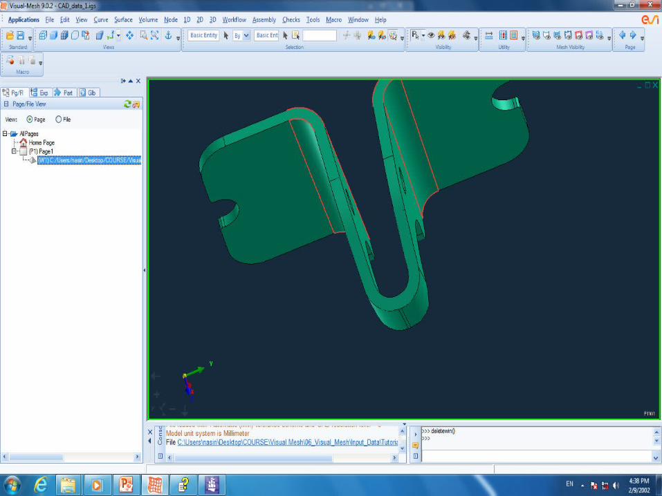
Visual Environment
Objective:1. learn how to import CAD models2. Familiar with GUI of Visual Environment3. T-joint model design4. Familiar with mesh function 5. Meshing of T-Joint model6. Meshing and design welded flange7. Meshing and design turbine blade

Menu Bar ToolbarEx
plor
er
Win
dow
Mod
elwin
dow

Selection Wizard

Application Manager
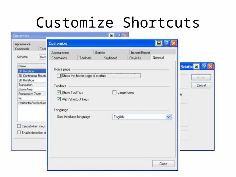
Customize Shortcuts
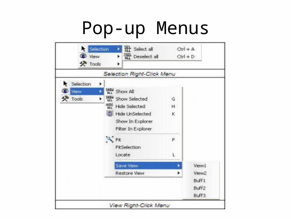
Pop-up Menus

Part Table• The Part Table is used to control part visualization. It allows you to set the
display method (such as Shaded, Wire Frame, etc.), assign colors, or visualize different attributes of the parts.
• 1. State• 2. ID (Part ID)• 3. Name• 4. DM (Display Method)• 5. Last Column Attribute

Point and Vector Definition
– Create / modify a node in 3D space.– Create / modify a point in 3D space.– Create / modify a curve by locating and modifying the
construction points that constitute it.– Locate the orientation vector / node of a line element
in space.– Locate the offset vector of a line element in space.– Vector, Axis and Plane definition.– Create / modify a coordinate system by locating and
modifying the direction of its axes.

Plane / Vector / Axis DefinitionPick three or two points Select one of the X, Y or Z-
axes of the modeling system for vector definition.

shortcutsDel Delete F10 Show Element Quality
A MoveView3 Alt + F4 Exit
B Undo view Alt + G Print Preferences
C Define View Point Shift + F11 Renumber
D Zoom Pro Shift + F1 Advanced Renumber
F Fit F7 Align
G Show F9 Trim/Split
H Hide Shift + X Section XY
K Hide Unselected Shift + F3 Boundary
L Locate Ctrl + F10 FullScreen
N Neighbour + Z ZoomArea
P Part Or Element S Panoramic
R Load Selection F4 Measure
W Save Selection Ctrl + F10 Copy

File OptionsCAD files PAM-CRASH LS-DYNANASTRANMADYMOSYSTUSASCII PRO-CAST filesPAM-CEM filesPAM-MEDYSAPATRAN MOSAICSTRIM100 ANSYSSIMEXABAQUSVDBIGESCATIA V4CATIA V5
*.vdb
*.ASC
This section contains information about setting the configuration of the Visual-Environment Generalbehavior. Using the General tab in Preferences panel you can set preference for the Recent File List,Window drag effects, Context menu style, Application activation, Document tiling, Sensitivity of arrow keys.
Entity Selector
In Visual-Environment:• Nodes, elements are FE entities.• Surfaces, stitched surfaces, curves and vertices
are CAD entities.• ellipsoid, cylinders and planes are rigid body
entities.• Parts, groups, etc., are other types of entities.

Entity Relationships• Element By Element Selects all picked elements.• Element By Part Selects all elements that belong to the picked part.• Element By Node Selects all elements that share the picked node.• Element By Assembly Selects all elements that belong to the picked assembly.• Element By Group Selects all elements that share the picked group.• Element Attached To Element Selects all elements attached to the picked elemElement Attached To
Nodes Selects all elements attached to the picked node• Parts Attached To Welds• Selects all parts attached to the picked weld• elements.• Welds Attached To Parts Selects all welds attached to the picked parts.• Plink Between Parts• Selects all plink elements that lie between the two parts• picked.• Spring Between Quad• Selects all spring elements that lie between the pair of quad• elements picked.
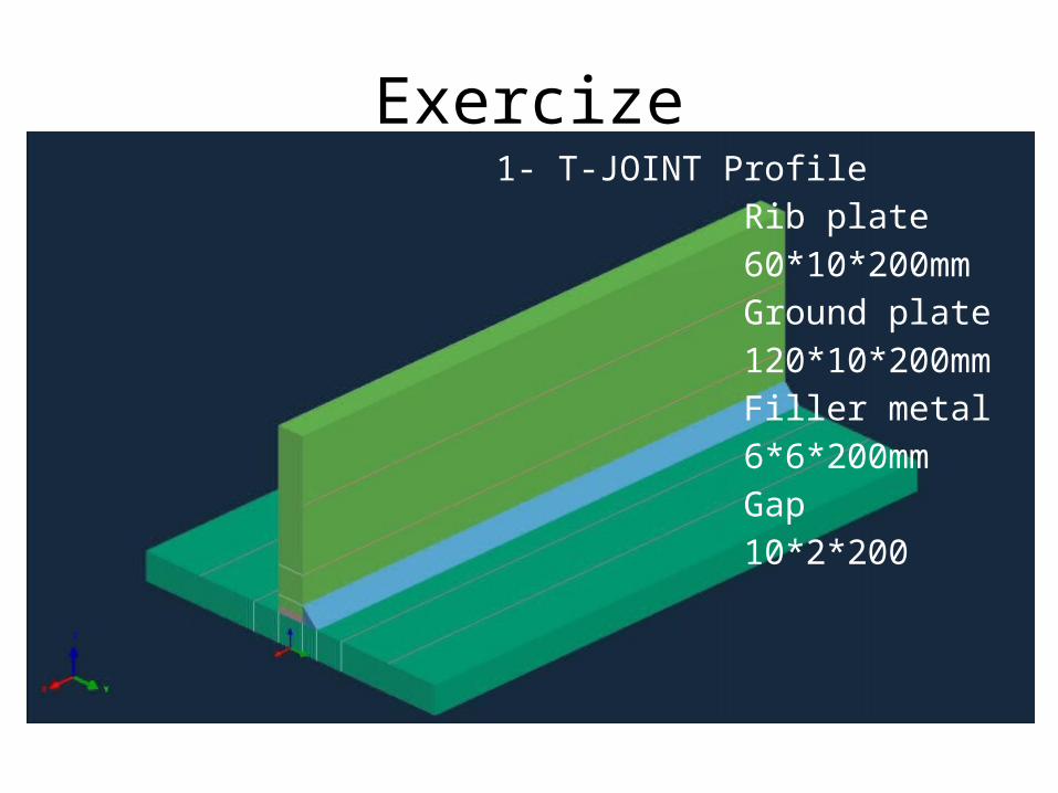
Exercize1- T-JOINT Profile Rib plate 60*10*200mm Ground plate 120*10*200mm Filler metal 6*6*200mm Gap 10*2*200
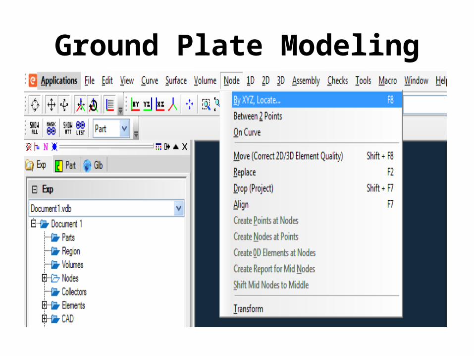
Ground Plate Modeling
• Click File -> New or press CTRL+N Files• Nodes Creation 0,-60,10 0,60,10 0,-60,0 0,60,0
To Create a Surfaces with the required size, you need to create Nodes. With the help of these nodes Surface and curves will be created.

Surface Creation by Blend• Post Blend GUI from Surface menu (Surface -> Blend (Spline) )• Change Mesh only option to Surf Only option• In the model window pick Node 1 & Node 2 and confirm by middle
mouse button. This becomes first primary edge for the blend Surface.
• Pick Node 3 & Node 4 and confirm by middle mouse button. This becomes second primary edge for the blend Surface.
• Click on OK to confirm. The new surface will be created and it will be in Part 1 which is default.

Surface Creation by Sweep• Post Sweep GUI from Surface menu (Surface -> Sweep (Drag) )• Change sweeping curve option to Multiple Curves and enter 200 in the
Distance field.• Change Mesh only option to Surf Only option • Enter 1 in Part ID filed• Pick the top edge of the newly created Surface • After confirming the sweep curve selection, a Vector Definition GUI is posted• Select Global Axis as the Vector definition option and click on Flip to make
the vector in - X direction • Click on Ok/Close in the Vector Definition GUI to accept the Vector and close
the GUI• Look the preview of the surface to be generated and confirm it by clicking on
Ok in Sweep GUI

Surface Transform
• Post Surface Transform GUI from Surface menu (Surface -> Transform)
• Toggle on Fix option for Y Axis and Z Axis and enter -200 in the dX field
• Select the Surface created by blend and confirm by clicking on Update Entities
• Toggle Copy option and keep the other options default
• Confirm the transformation by Clicking on Copy

Rib Modeling
• Nodes Creation (0,-5,12) (0,-5,72)(0,5,12)(0,5,72)• Surface Creation by Blend• Surface Creation by Sweep• Surface Transform

Filler Material Modeling
• Nodes Creation (0, 5, 16) (0, 5, 10) (0, 11, 10)• Surface Creation by Blend• Surface Creation by Sweep• Surface Transform

Gap material Modeling
• Post Drop Points/Curves/ Nodes GUI from Nodes menu. (Nodes -> Drop (Project))or Nodes Creation (0,-5,10)
• Surface Creation by Blend• Surface Creation by Sweep• Surface Transform

Initial model
Curves Generation• Post Nodes Transform GUI from Nodes Menu (Nodes -> Transform)• Select the Node 12 and confirm by middle mouse button on click on Update
Entities• In the posted GUI, Fix X and Z axis. Enter -10 in the dY field and toggle on the
Copy option• Copy the node by clicking on button Copy• Similarly select the Node 11 and confirm by middle mouse button on click on
Update Entities• Fix X and Z axis. Enter 10 in the dY field Copy the node by clicking on Copy• select the Node 9 and confirm by middle mouse button on click on Update
Entities• Fix X axis and Y axis, free the Z Axis. Enter 10 in the dZ field Copy the node
by clicking on Copy• The new Nodes will have the IDs 13, 14 & 15.

Creating Curve by Sketch• Post Sketch GUI from Curve menu (Curve -> Sketch)• With all the default options pick the pairs of nodes that are original and
copied by drop options in the earlier step• See the below picture for the curves to be created in the below picture• Once the pair of nodes is selected confirm by middle mouse button to
accept the created Curve.• Make sure that the Curves will be in Part 5• To make sure the picked point is on the Node only follow the below
procedure.NOTE: Pick the first node for the first Curve. It shows the point handle by Curve (a Mark)Once again click on the same node or the Point handle; it posts a point definition GUI as shown below.

Saving the Model
• The model can be saved in different formats: 1- To save VDB format 2-To Export the Model in IGES format
MODEL BULDING• Curve• Surface• Volume• Node• 1D• 2D• 3D• Transform• Change PID• Properties• Assembly• Checks• Tools
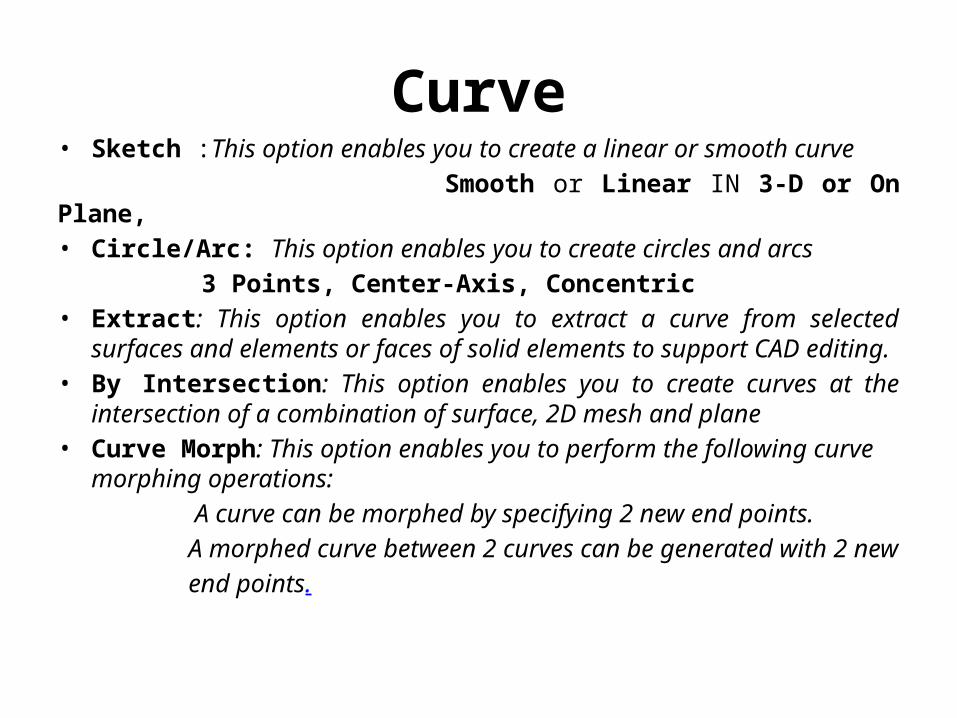
Curve• Sketch :This option enables you to create a linear or smooth curve Smooth or Linear IN 3-D or On Plane,• Circle/Arc: This option enables you to create circles and arcs 3 Points, Center-Axis, Concentric• Extract: This option enables you to extract a curve from selected surfaces
and elements or faces of solid elements to support CAD editing.• By Intersection: This option enables you to create curves at the
intersection of a combination of surface, 2D mesh and plane• Curve Morph: This option enables you to perform the following curve
morphing operations: A curve can be morphed by specifying 2 new end points. A morphed curve between 2 curves can be generated with 2 new end points.
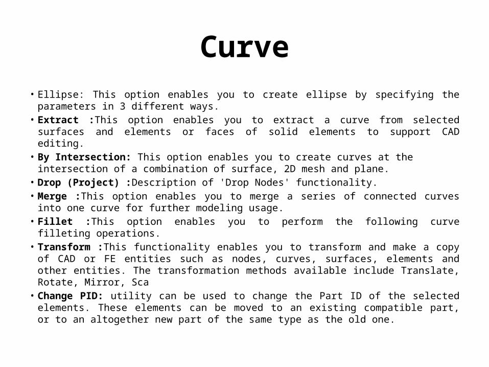
Curve• Ellipse: This option enables you to create ellipse by specifying the parameters in 3
different ways.• Extract :This option enables you to extract a curve from selected surfaces and elements
or faces of solid elements to support CAD editing.• By Intersection: This option enables you to create curves at the intersection of a
combination of surface, 2D mesh and plane.• Drop (Project) :Description of 'Drop Nodes' functionality.• Merge :This option enables you to merge a series of connected curves into one curve for
further modeling usage.• Fillet :This option enables you to perform the following curve filleting operations.• Transform :This functionality enables you to transform and make a copy of CAD or FE
entities such as nodes, curves, surfaces, elements and other entities. The transformation methods available include Translate, Rotate, Mirror, Sca
• Change PID: utility can be used to change the Part ID of the selected elements. These elements can be moved to an existing compatible part, or to an altogether new part of the same type as the old one.
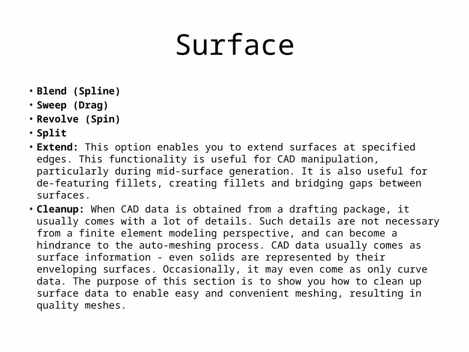
Surface• Blend (Spline)• Sweep (Drag)• Revolve (Spin)• Split• Extend: This option enables you to extend surfaces at specified edges. This
functionality is useful for CAD manipulation, particularly during mid-surface generation. It is also useful for de-featuring fillets, creating fillets and bridging gaps between surfaces.
• Cleanup: When CAD data is obtained from a drafting package, it usually comes with a lot of details. Such details are not necessary from a finite element modeling perspective, and can become a hindrance to the auto-meshing process. CAD data usually comes as surface information - even solids are represented by their enveloping surfaces. Occasionally, it may even come as only curve data. The purpose of this section is to show you how to clean up surface data to enable easy and convenient meshing, resulting in quality meshes.

Topo Mesh / Surface Mesh• Split and merging of faces.• Cleanup of bad Trim/Overlap regions (interactive and automatic).• Stitching edges within/across topology (interactive and automatic).• Alignment of domain lines by replacing corners (vertices).• Creation of washers around holes (interactive and automatic).• Filling cavities (interactive and automatic).• Creation and deletion of vertices (break points) along edges.• Stitching of surrounding elements with topology.• Control of number of seeds, synchronization of seeds of 2 edges, biasing of seeds.• Creation and deletion of mesh on faces (specification of mesh type and meshing
schemes).• Creation and deletion of analysis points.• Display controls for faces.• Display options for seeding, topology, mesh, surface, etc.• Automatic options to do intelligent editing and seeding.

Welded Flange1- Draw semicircle (part 1)
r=1000,1770, 1922 angle: 180,2- Rotate
angle=903- Draw R= 1000 angle= 180 , Rotate angle=904- Plot points
x=2422 ,y= 266.5,436.5,700, -266.5,-436.5,-7005- Drop points on arcs6- Sketch splitter lines(part 2)7- delete un useful lines7- Fillet line(part 1)8- Create external surface by sweep(part 4) 9- Create symmetric surfaces by blend(part 5) 10- Create welded surface by blend(part 6) 11- Create internal surfaces by blend(part 7)
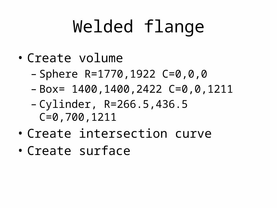
Welded flange
• Create volume– Sphere R=1770,1922 C=0,0,0– Box= 1400,1400,2422 C=0,0,1211– Cylinder, R=266.5,436.5 C=0,700,1211
• Create intersection curve• Create surface
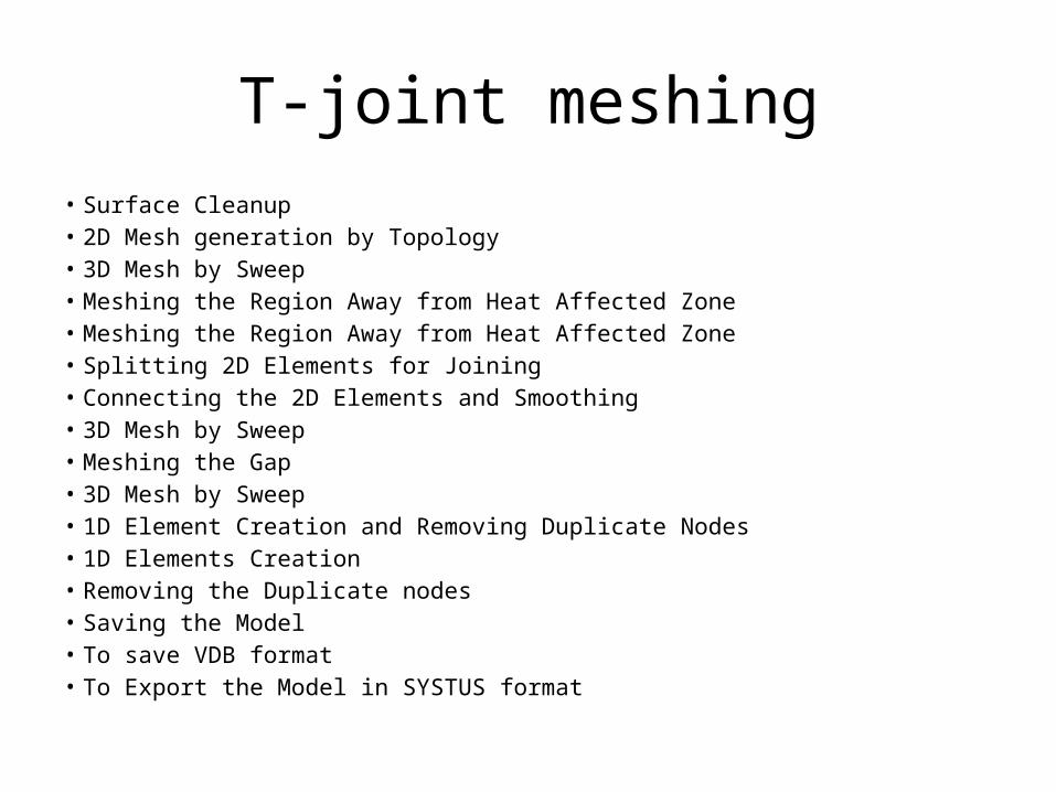
T-joint meshing• Surface Cleanup• 2D Mesh generation by Topology • 3D Mesh by Sweep• Meshing the Region Away from Heat Affected Zone• Meshing the Region Away from Heat Affected Zone• Splitting 2D Elements for Joining • Connecting the 2D Elements and Smoothing • 3D Mesh by Sweep• Meshing the Gap• 3D Mesh by Sweep• 1D Element Creation and Removing Duplicate Nodes• 1D Elements Creation• Removing the Duplicate nodes• Saving the Model• To save VDB format• To Export the Model in SYSTUS format