Vista Technologies, Inc. Radiation Safety ProgramVista Technologies, Inc. Radiation Safety Program...
27
Vista Technologies, Inc. Radiation Safety Program PROCEDURE - 17 SOIL, WATER AND SEDIMENT SAMPLING TECHNIOUES TECHNOLOGIES 1019 Central Parkway North, Suite 115 San Antonio, Texas 78232 210-494-4282
Transcript of Vista Technologies, Inc. Radiation Safety ProgramVista Technologies, Inc. Radiation Safety Program...
Vista Technologies, Inc. Radiation Safety Program
PROCEDURE - 17
SOIL, WATER AND SEDIMENT SAMPLING TECHNIOUES
TECHNOLOGIES
1019 Central Parkway North, Suite 115 San Antonio, Texas 78232
210-494-4282
TABLE OF CONTENTS
1. SYSTEMATIC AND BIASED SURFACE SOIL RADIOLOGICAL SAMPLING ............................................ 1
1. 1. Necessary Supplies ........................................................................................................................................ 1
1.2. Specific Instructions ...................................................................................................................................... 2
1.3. Sam pling Techniques .................................................................................................................................... 3
1.4. Docum entation .............................................................................................................................................. 4
1.5. Post-Rem edial Action Survey ....................................................................................................................... 5
1.6. Obtaining Representative Sam ples ......................................................................... ............................... 6
2. SUBSURFACE SOIL RA DIOLOGICAL SAM PLING ................................................................................. 6
2.1. 2.1 Necessary Supplies .................................................................................................................................. 6
2.2. Specific Instructions ...................................................................................................................................... 7
2.3. Sam pling Techniques .................................................................................................................................... 8 2.4. Hand Auger Sam ples ..................................................................................................................................... 8
2.5. Split-Spoon Sam ples. .................................................................................................................................... 9
2.6. Shelby Tube Sam ples ................................................................................................................................... 10
2.7. Power Auguring .......................................................................................................................................... 10
2.8. Other Sam pling Techniques ........................................................................................................................ 11
2.9. Docum entation ............................................................................................................................................ 12
3. W A TER AND SEDIM ENT SAM PLIN G ...................................................................................................... 13
3.1. Introduction ................................................................................................................................................ 13
3.2. Necessary Supplies ...................................................................................................................................... 13
3.3. Specific Instructions .................................................................................................................................... 14
3.4. Suspended Fraction ..................................................................................................................................... 14
3.5. Sedim ent Sam ples ....................................................................................................................................... 15
List of Attachments
Attachment Number
23
29
30
Name of Attachment
Walkover Gamma Ray Scan Data Sheet Form
Field Sample Collection Form
Custody Seal Form
Procedure 17 Attachments
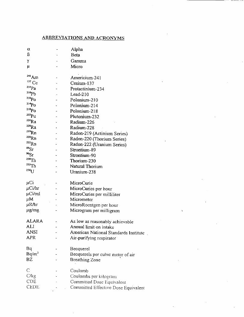
ABBREVIATIONS AND ACRONYMS
cx - Alpha 13 - Beta y - Gamma
-- Micro
241Am - Americium-241 137 Ce - Cesium-137 234Pa - Protactinium-234 2 1oPb - Lead-210 210po - Polonium-21 0 24po - Polonium-214 218po - Polonium-218 232Pu - Plutonium-232 226Ra - Radium-226 22 8Ra - Radium-228 2 19'pn - Radon-219 (Actinium Series) 220pn - Radon-220 (Thorium Series) 222Rn - Radon-222 (Uranium Series) 89Sr - Strontium-89 9OSr - Strontium-90 230Th - Thorium-230 232Th - Natural Thorium 238u- Uranium-238
giCi - MicroCurie [LCi/hr - MicroCuries per hour gCi/ml - MicroCuries per milliliter gM- Micrometer gR/hr - MicroRoentgen per hour jig/mg - Microgram per milligram
ALARA - As low as reasonably achievable ALl - Annual limit on intake ANSI - American National Standards Institute APR - Air-purifying respirator
Bq - Becquerel Bq/m' - Becquerels per cubic meter of air BZ - Breathing Zone
C Coulomb C/kg Coulombs per kilogram CDE Committed Dose Equivalent CEDE Committed Effective Dose Equivalent
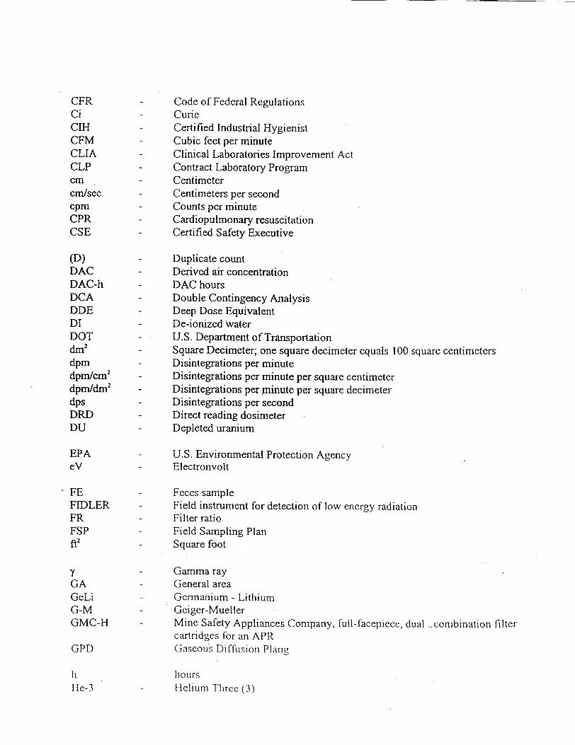
CFR Code of Federal Regulations Ci - Curie CIH - Certified Industrial Hygienist CFM - Cubic feet per minute CLIA - Clinical Laboratories Improvement Act CLP - Contract Laboratory Program cm - Centimeter cm/sec - Centimeters per second cpm - Counts per minute CPR - Cardiopulmonary resuscitation CSE - Certified Safety Executive
(D) - Duplicate count DAC - Derived air concentration DAC-h - DAC hours DCA - Double Contingency Analysis DDE - Deep Dose Equivalent DI - De-ionized Water DOT - U.S. Department of Transportation dm2
- Square Decimeter; one square decimeter equals 100 square centimeters dpm - Disintegrations per minute dpm/cm2 - Disintegrations per minute per square centimeter dpm/dm2 - Disintegrations per minute per square decimeter dps - Disintegrations per second DRD - Direct reading dosimeter DU - Depleted uranium
EPA - U.S. Environmental Protection Agency eV - Electronvolt
FE - Feces sample FIDLER - Field instrument for detection of low energy radiation FR - Filter ratio FSP - Field Sampling Plan t2
- Square foot
Y - Gamma ray GA - General area GeLi - Germanium - Lithium G-M - Geiger-Mueller GMC-H - Mine Safety Appliances Company, full-facepiece, dual ..combination filter
cartridges for an APR GPD Gaseous Diffusion Plang
h hours He-3 - Helium Three (3)

HEPA - High efficiency particulate air HN0 3 - Nitric acid HP - Health Physics hr - Hour HS - Hot spot (radiation) HSP - Site-specific Health and Safety Plan HWP - Hazardous Work Permit
ICRP - International Commission on Radiological Protection ID - Identification IDLH - Immediately dangerous to life or health IDW - Investigation derived waste IP - Ionization potential IVC - Independent verification contractor
keV - Kiloelectronvolt kg - Kilogram
LANL - Los Alamos National Laboratory 1pm - Liters Per Minute
MCA - Multi-channel analyzer MDA - Minimum detectable activity meV - Millielectronvolt m - Meter m2 - Squared Meters M3
- Cubic meters mCi - MilliCurie MSHP - Manager, Vista Safety and Health Program mil - 1/1000 inch ml - Milliliter mm - Millimeter mR - MilliRoentgen mR/hr - MilliRoentgens per hour mrem - Millirem mrem/hr - Millirems per hour MSA - Mine Safety Appliances Company MSDS - Material Safety Data Sheet MSHA - Mine Safety and Health Administration
Nal - Sodium iodide NCA - Nuclear Criticality Analysis NCS - Nuclear Criticality Safety NCRI - National Council on Radiation Protection and Measurements NF.A Nuclear Energy Agency NIST National Institute of Science and Technology

NIOSH National Institute for Occupational Safety and Health n. o. s. - Not otherwise specified
NPDES - National Pollutant Discharge Elimination System NRC - U.S. Nuclear Regulatory Commission NS - Nose swipe NTIS - National Technical Information Service NVLAP - National Voluntary Laboratory Accreditation Program
OHSO - On-Site Health and Safety Officer ORNL - Oak Ridge National Laboratory ORPO - On-Site Ionizing Radiation Protection Officer OSHA - U.S. Occupational Safety and Health Administration
pCi - PicoCurie pCi/gm - PicoCuries per gram pCi/I - PicoCuries per liter P.E. - Professional Engineer PF - Protection Factor PIC - Pocket Ionization Chamber PM - Project Manager PMT - Photomultiplier Tube PPE - Personal Protective Equipment PRP - Potentially Responsible Party PRS - Portable ratemeter/scaler PVC - Polyvinyl chloride
QA - Quality assurance QC - Quality control
R - Roentgen RA - Restricted (radiation) area rad - Radiation absorbed dose RAS- I - Kurz air sampling pump flow calibration kit REM - Roentgen equivalent man RHSC - Radiation Health and Safety Committee RSO VISTA Radiation Safety Officer RWP Radiation work permit
SAP - Sampling and Analysis Plan SCBA - Self-contained breathing apparatus SRD - Self-reading dosimeter
"TODI - Total Organ Dose Equivalent TLD - Thernoluminescent dosimeter ']'\VA IF ime-weighted average

U-" Natural uranium UR - Urine sample U.S. - United States
VISTA - Vista Technologies, Inc. VSHP - VISTA Safety and Health Program VRSP - VISTA Radiation Safety Program
WL - Working Level WP - Work Plan

Page 1
SOIL, WATER, AND SEDIMENT SAMPLING TECHNIQUES
The following sections discuss systematic and biased surface soil radiological sampling, subsurface soil radiological sampling, and water and sediment sampling.
1. SYSTEMATIC AND BIASED SURFACE SOIL RADIOLOGICAL SAMPLING
The purpose of these procedures for systematic and biased surface soil radiological sampling is to establish radiological systematic and biased surface soil sampling techniques for collecting surface soil during remedial action, characterization or other activities at Vista project work sites. These procedures supplement the Field Samnpling Plan (FSP) or Sampling and Analysis Plan (SAP) for a specific Vista project work site.
This procedure describes the systematic and biased surface soil radiological sampling techniques, applicable forms, sample labels, radioactive decontamination of sampling equipment and identification of sampling locations. Additional guidance is provided for requirements as specified within NUREG Nuclear Regulatory Guide) and Environmental Protection Agency (EPA) documents.
The applicable references are:
* NUREG/CR 5849. "Manual tbr Conducting Radiological Surveys in Support of License Termination;
* NUREGiCR-5512, "Residual Radioactive Contamination From Decommissioning;" "* "Test Methods For Evaluating Solid Waste, Physical/Chemical Methods." SW-846.
Third Edition. Proposed Update Package, "* "Test Methods For Evaluating Solid Waste, Physical/Chemical Methods," SW-846,
Third Edition Revised. "* "A Compendium of Super-fund Field Operations Methods." EPA 540 P-87 001 * Vista's RSP Procedurc 15 "Monitoring and Surveying."
1.1. Necessary Supplies
* Sample containers (500 ml Nalgene® jars, etc); * Sampling equipment as required; * Labels; "* "Field Sample Collection Form," shown as Attachment 29; * Measuring tape; "* "Custody Seal," shown as Attachment 30; * Alconox® or Liquinox® (or standard brand of phosphate-free detergent), De-Ionized
(DI) water, spray bottles, 5-gallon plastic buckets (3), and soft bristle brushes (3); and • Radiological field sample collection logbook(s) "* (hIouluid ~cneiratingL Radar ((GPR) "* Facilti area diagram: "* Flags to mark sample hocatioMv.:
Procedure 17-Soil, Water & Sediment Sampling 01/13/99
Note: For the purposes of this document. Ionizing Radiation includes certain types of Non-Ionizing Radiation

Page 2
* Clipboard an(] pen
1.2. Specific Instructions
Sample collection for radiological analysis on Vista project work sites requires that samples be collected consistent with the guidance specified in NUREG and EPA documents. This includes sampling technique, sampling equipment radioactive decontamination, and documentation.
The frequency and number of systematic surface soil samples usually will be specified in the FSP or SAP. The number of samples collected will depend on site-specific information such as elevated y ray readings as detected from 'y ray scans conducted in accordance with Vista's RSP Procedure 15, "Monitoring and Surveying - Gamma Ray Exposure Rate Surveys at One Meter in Open and Enclosed Areas, and Walkover Gamma Ray Scan." Direction from instruction guides, FSPs, SAPs, or other written instruction are required for all sampling events.
Prior to initial sampling, tools and equipment must be cleaned as specified below:
* Sampling tools for radioactive materials must be washed using a solution of Alconox® or Liquinox® and water. A soft bristle brush should be used to remove any visible material from sampling tools and equipment. Sampling tools will be rinsed with DI water and allowed to air dry. After drying, tools should be covered with aluminum foil or wrapped in plastic to preclude their radioactive contamination until used.
Prior to initial sampling, a bound, page-numbered sample logbook will be established, and during sampling the information below will be entered:
* Purpose of samplinig (e.g., characterization, remedial action, and so forth); * Coordinates of sampling point, and depth of sampling; * Name of field technician doing the sampling; * Type of sample (e.g., soil, water, and so forth); and * Number of samples and volume taken. * Description of sampling point and sampling methodology; * Date and time of collection; * Sample identification number(s); * Sample distribution and method of transportation (e.g., cooler, United Parcel Service or
Federal Express); * Name of analytical laboratory; * References such as maps or photographs of the sampling site; * Field observations such as weather conditions, wind direction, wind speed, and relative
humidity must be entered into the sample logbook; * Any measurements taken (e.g.,, pH, soil density, flammability, explosivity); * Signatures of field technician who took the sample or made any observations; * Method used for radioactive decontamination of sampling equipment; and * For composite samples, method of compositing.
Procedure 17-Soil, Water & Sediment Sampling 01/13/99
Note: For the purposes of this document, Ionizing Radiation includes certain types of Non-Ionizing Radiation
Page 3
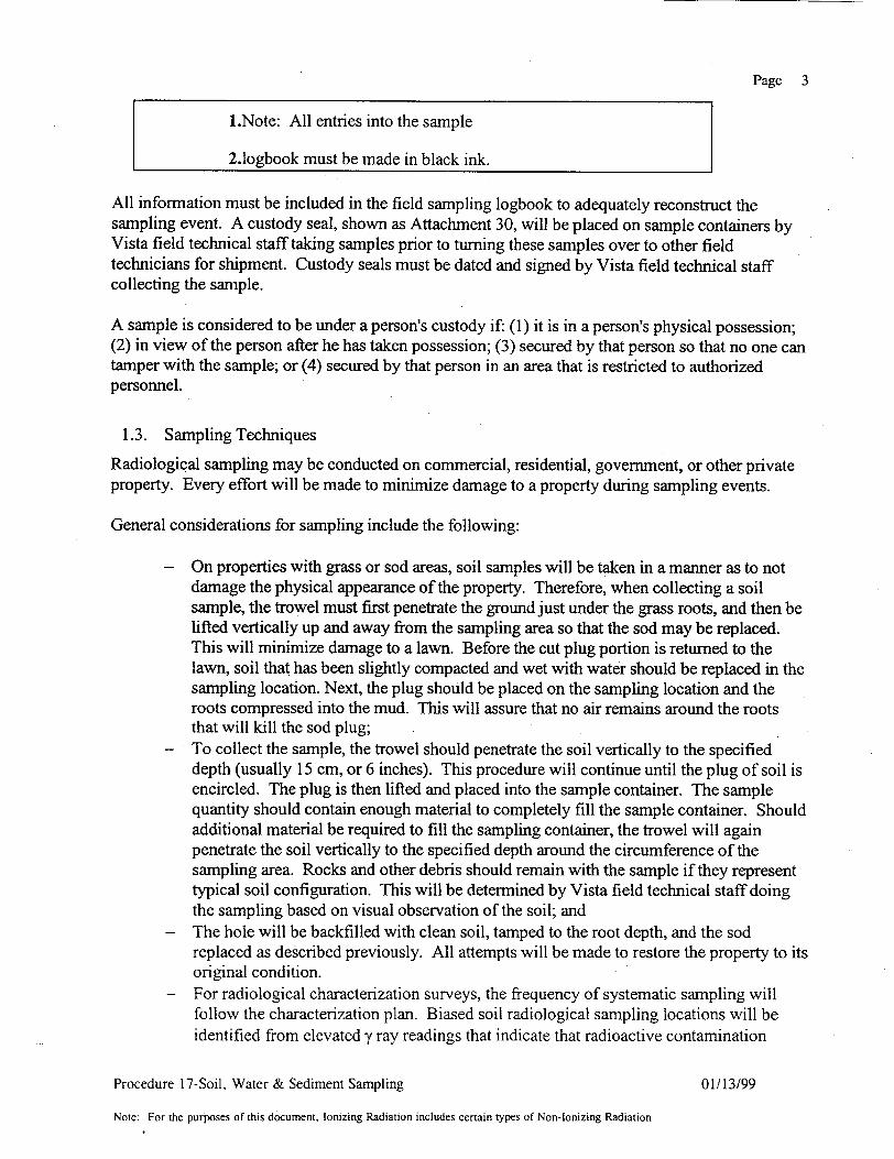
1.Note: All entries into the sample
2.logbook must be made in black ink.
All information must be included in the field sampling logbook to adequately reconstruct the sampling event. A custody seal, shown as Attachment 30, will be placed on sample containers by Vista field technical staff taking samples prior to turning these samples over to other field technicians for shipment. Custody seals must be dated and signed by Vista field technical staff collecting the sample.
A sample is considered to be under a person's custody if: (1) it is in a person's physical possession; (2) in view of the person after he has taken possession; (3) secured by that person so that no one can tamper with the sample; or (4) secured by that person in an area that is restricted to authorized personnel.
1.3. Sampling Techniques
Radiological sampling may be conducted on commercial, residential, government, or other private property. Every effort will be made to minimize damage to a property during sampling events.
General considerations for sampling include the following:
- On properties with grass or sod areas, soil samples will be taken in a manner as to not damage the physical appearance of the property. Therefore, when collecting a soil sample, the trowel must first penetrate the ground just under the grass roots, and then be lifted vertically up and away from the sampling area so that the sod may be replaced. This will minimize damage to a lawn. Before the cut plug portion is returned to the lawn, soil that has been slightly compacted and wet with water should be replaced in the sampling location. Next, the plug should be placed on the sampling location and the roots compressed into the mud. This will assure that no air remains around the roots that will kill the sod plug;
- To collect the sample, the trowel should penetrate the soil vertically to the specified depth (usually 15 cm, or 6 inches). This procedure will continue until the plug of soil is encircled. The plug is then lifted and placed into the sample container. The sample quantity should contain enough material to completely fill the sample container. Should additional material be required to fill the sampling container, the trowel will again penetrate the soil vertically to the specified depth around the circumference of the sampling area. Rocks and other debris should remain with the sample if they represent typical soil configuration. This will be determined by Vista field technical staff doing the sampling based on visual observation of the soil; and
- The hole will be backfilled with clean soil, tamped to the root depth, and the sod replaced as described previously. All attempts will be made to restore the property to its original condition.
- For radiological characterization surveys, the frequency of systematic sampling will follow the characterization plan. Biased soil radiological sampling locations will be identified from elevated y ray readings that indicate that radioactive contamination
Procedure 17-Soil, Water & Sediment Sampling 01/13/99
Note: For the purposes of this document. Ionizing Radiation includes certain types of Non-lonizing Radiation

Page 4
exists. In areas where a ray-emitting contamination is not present, Vista field technical staff will have to determine biased sample locations based on site characteristics (i.e., runoff areas, sumps, and so forth).
1.4. Documentation
Using the Field Sample Collection Form each soil sample collected will be assigned a sequential number and recorded in the field sample collection logbook. Sample information should then be documented on the form shown as "Field Sample Collection Form," Attachment 29. Documentation on the Field Sample Collection Form should contain the following information:
Results of contamination survey; Site number; Site name; Activity support (job) number; Name of Vista field technical staff doing the sampling;
- Sample identification number; - Sample grid points; - Sample type; - Time sample was collected; - Date sample was collected; - Sample preservative used; - Purpose; - Depth (in centimeters or feet); - Analysis required; - Remarks;
Chain-of-custody information; Recorded by; Results of excessive removable contamination scan; Date and time form was completed; Number of samples in each shipping container; Total number of samples in shipment; and Total number of boxes in shipment.
The names of field technician who collected the samples should be recorded ift the field sample collection logbook. Document all facts about the sample on the Field Sample Collection Form and enclose the original Field Sample Collection Form with the samples to be shipped to the analytical laboratory.
To help ensure that each sample has been properly handled, a chain-of-custody procedure must be followed. For chain-of-custody reporting, enter the following information in the appropriate box of the Field Sample Collection Form:
Survey for excessive radioactive material prior to transportation;
Procedure 17-Soil, Water & Sediment Sampling 01/13/99
Note: For the purposes of this document, Ionizing Radiation includes certain types of Non-Ionizing Radiation

Page 5
Reason the sample is being scanned is for assuring there is no excessive radioactive material, prior to transportation released F'rom the site (i.e.. shipment, archival, analysis, and so forth); Person physically relinquishing the sample to the carrier (consignee); Person or consignor (e.g., United Parcel Service or Federal Express); Date and approximate time the sample was released to the consignor (time the sample leaves the site or is delivered to the consignor); and Personnel at the analytical laboratory (or location that receives the sample) will acknowledge receipt of the sample on the next line of the chain-of-custody box by their signature in the "received by" column, and by entering the date and time the sample was received.
A copy of the Field Sample Collection Form should be provided to the Vista Project Manager (PM) and the Vista Radiation Safety Officer (RSO) by the Vista On-site Radiation Protection Officer (ORPO). A copy should be retained for the on-site records by the Vista ORPO. Upon receipt of samples in the analytical laboratory, receiving personnel should acknowledge the shipment by completion of appropriate information in the chain-of-custody section of the Field Sample Collection Form. The laboratory must also note within the remarks section of this form if custody seals have been violated.
1.5. Post-Remedial Action Survey
Upon completion of excavation, a 10 m by 10 m grid will be established inside the excavated area. The surface area inside the grid block will be scanned using an unshielded y ray scintillation detector. The detector is held near the ground surface, and is slowly moved from side to side as the surveyor advances. This procedure is conducted over the entire excavation and documented on the form shown as "Walkover Gamma Ray Scan Data Sheet Form," Attachment 23.
To reach this step within this procedure, all y ray-emitting contamination, including hot spots, should have been removed. To further confirm or document the radiological status of the excavation, shielded y.ray (cone shield) apparatus scintillation detector readings should be conducted at locations as specified by the work plan. This information may be used to infer actual radionuclide concentration by cross calibration of cpm to pCi/g. This does not replace actual soil sample requirements as specified within the Vista procedures for post-remedial action sampling. Detection of any residual radioactive contamination during cone-shield apparatus surveys will require additional excavation and repetition of steps of the Post-Remedial Action Survey.
Gamma ray exposure rate measurements will be obtained at 1 meter above the ground as described in Procedure 15 "Moniloring and Surveying,". The final step in confirming compliance with regulatory remedial action guidelines for soil is to collect soil samples. The samples provide documented evidence supporting the certification of the property for release for unrestricted use. Soil samples should, therefore, be representative of the entire sampled grid block(s) to demonstrate that a 100 m2 area meets the averaging criteria as specified in the protocol.
Procedure 17-Soil, Water & Sediment Sampling 01/13/99
Note: For the purposes of this document, Ionizing Radiation includes certain types of Non-Ionizing Radiation

Page 6
1.6. Obtaining Representative Samples
A series of 2.5 cm diameter plugs, 15 cm deep will be collected from 25 equally spaced locations within each 100-m2-grid block. The samples will be placed in a plastic bag and blended (wet). The wet sample will then be placed in a 2-liter Marinelli beaker and shipped to the analytical laboratory for initial wet count screening by y ray spectroscopy. Additional biased hot spot samples will be acquired in areas where 'y survey data may be subject to Independent Verification Contractor (IVC) scrutiny with respect to meeting criteria. The samples will be noted as "biased" and may be taken in 500-ml Nalgene® jars.
After the initial y ray and neutron count, the entire soil sample will be dried and pulverized. After samples have been pulverized and thoroughly blended, an aliquot that completely fills a 500 ml Marinelli beaker will be taken from the blended sample. The remaining soil will be placed in a container, identified, and archived.
The 500-ml Marinelli beaker will be sealed and allowed to equilibrate if Ra-226 analyses are required. The results obtained from counting the "dry" sample will be transmitted to Vista for inclusion on post remedial action reports.
2. SUBSURFACE SOIL RADIOLOGICAL SAMPLING
The purpose of this procedure is to establish radiological sampling techniques for collecting subsurface soil samples during remedial action, characterization or other activities at Vista project work sites. This procedure describes subsurface soil sampling techniques, applicable forms, sample labels, radioactive decontamination of sampling equipment and identification of sampling locations. Additional guidance is provided for requirements as specified within NUREG and EPA documents.
Applicable references are:
"* "Test Methods For Evaluating Solid Waste, PhysicallChemical Methods," SW-846 Third Edition, Proposed Update Package;
"* "Test Methods For Evaluating Solid Waste, Physical/Chemical Methods," SW-846, Third Edition Revised, November;
"• "A Compendium Of Super-fund Field Operations Methods," EPA 540 P-87 001,
2.1. Necessary Supplies
* Sample containers - 500 ml Nalgene® jars; * Sampling equipment as required; * Labels; "* "Field Sample Collection Form," shown as Attachment 29; * "Custody Seal," shown as Attachment 30;
' Measuring tape; * Alconox® or Liquinox® (or standard brand phosphate-free detergent, Dc-lonized (D1)
water, spray bottles, 5-gallon plastic buckets (3), and soft bristle brushes (3); and
Procedure 17-Soil, Water & Sediment Sampling 01/13/99
Note: For the purposes of this document, Ionizing Radiation includes certain types of Non-Ionizing Radiation

Page 7
"* Radiological Field Sample Collection Logbook(s) "• Ground Penetrating Radar (GPR) * Facility area diagram; * Flags to mark sample locations; * Clipboard and pen.
2.2. Specific Instructions
Sample collection for radiological analysis on Vista project work sites requires that samples be collected as specified within NUREG and EPA documents. This includes sampling technique, sampling equipment radioactive decontamination, and documentation.
"* The frequency and number of subsurface soil samples will be determined by the site characterization plan, or by written guidance provided by the Vista PM. If the Vista PM makes decisions about the number or frequency of samples, he or she must advise the team leader for that site. The number of samples collected will depend on site-specific information such as elevated -y ray readings and direction from project management personnel to assure the property is adequately covered.
"* Instruction guides, FSPs, SAPs, or other written instruction are required for all sampling events. The Vista PM will provide necessary guidance documents.
"* Prior to initial sampling, tools and equipment must be thoroughly cleaned. Sampling tools will be washed using a solution of Alconox® or Liquinox® and water. A soft bristle brush will be used to remove any visible material from sampling tools and equipment. Sampling tools will be rinsed with DI water and allowed to air dry. After drying, tools will be covered with aluminum foil or wrapped in plastic to prevent radioactive contamination until used.
* Prior to initial sampling, a bound, page-numbered sample logbook will be used. During sampling the following information should be recorded in the logbook:
- Purpose of sampling (e.g., characterization, remedial action, and so forth); Release survey of material to be transported; Coordinates of sampling point, and depth of sampling;
- Names of field technician doing the sampling; - Sample matrix (e.g., soil, water, and so forth); - Number of samples and volume taken; - Description of sampling point and sampling methodology; - Date and time of collection; - Release scan; - Sample identification number(s); - Sample distribution and method of transportation (e.g., cooler, United Parcel
Service or Federal Express); - Name of analytical laboratory; and - References such as maps or photographs of the sampling site.
Procedure 17-Soil, Water & Sediment Sampling 01/13/99
Note: For the purposes of this document, Ionizing Radiation includes certain types of Non-Ionizing Radiation
Page 8
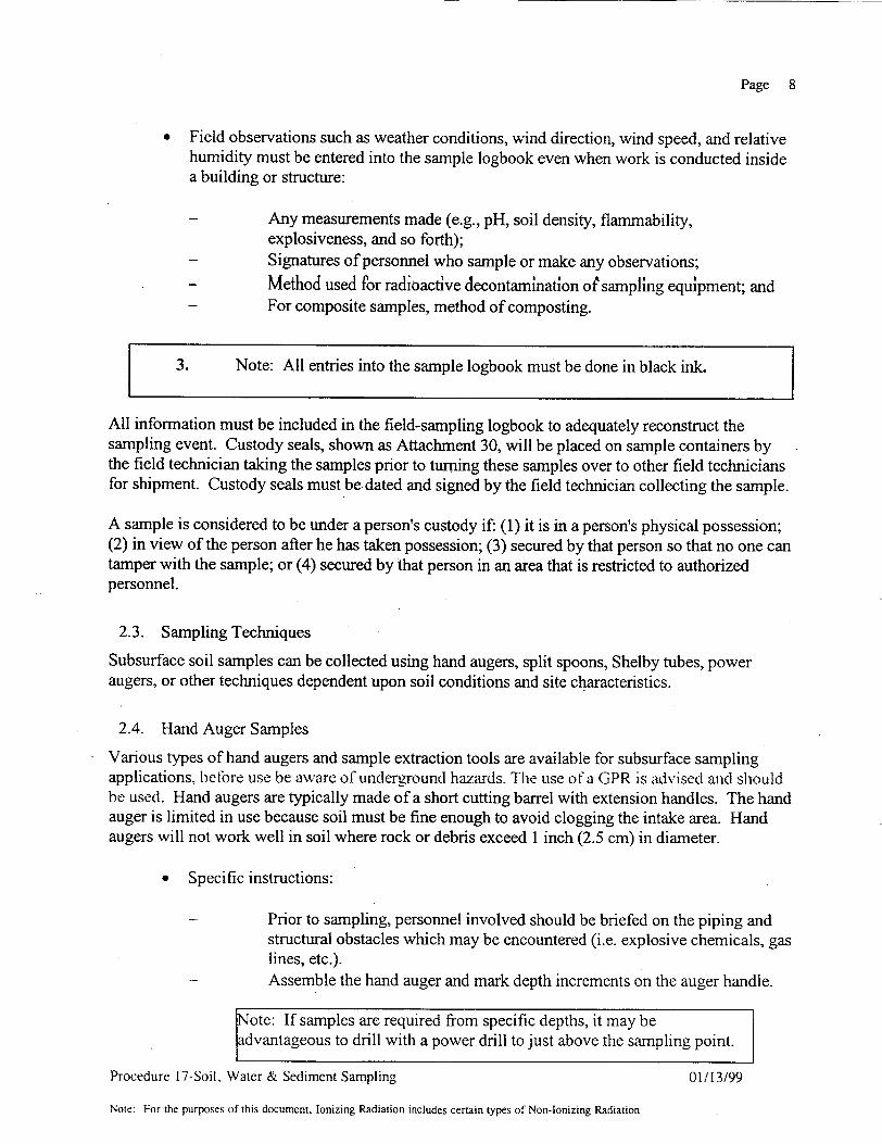
* Field observations such as weather conditions, wind direction, wind speed, and relative humidity must be entered into the sample logbook even when work is conducted inside a building or structure:
Any measurements made (e.g., pH, soil density, flammability, explosiveness, and so forth);
- Signatures of personnel who sample or make any observations; - Method used for radioactive decontamination oftsampling equipment; and - For composite samples, method of composting.
3. Note: All entries into the sample logbook must be done in black ink.
All information must be included in the field-sampling logbook to adequately reconstruct the sampling event. Custody seals, shown as Attachment 30, will be placed on sample containers by the field technician taking the samples prior to turning these samples over to other field technicians for shipment. Custody seals must be. dated and signed by the field technician collecting the sample.
A sample is considered to be under a person's custody if: (1) it is in a person's physical possession; (2) in view of the person after he has taken possession; (3) secured by that person so that no one can tamper with the sample; or (4) secured by that person in an area that is restricted to authorized personnel.
2.3. Sampling Techniques
Subsurface soil samples can be collected using hand augers, split spoons, Shelby tubes, power augers, or other techniques dependent upon soil conditions and site characteristics.
2.4. Hand Auger Samples
Various types of hand augers and sample extraction tools are available for subsurface sampling applications, belbre use be aware of underground hazards. The use of a GPR is advised and should be used. Hand augers are typically made of a short cutting barrel with extension handles. The hand auger is limited in use because soil must be fine enough to avoid clogging the intake area. Hand augers will not work well in soil where rock or debris exceed 1 inch (2.5 cm) in diameter.
* Specific instructions:
Prior to sampling, personnel involved should be briefed on the piping and structural obstacles which may be encountered (i.e. explosive chemicals, gas lines, etc.). Assemble the hand auger and mark depth increments on the auger handle.
Note: If samples are required from specific depths, it may be
advantageous to drill with a power drill to just above the sampling point.
Procedure 17-Soil, Water & Sediment Sampling 01/13/99
Note: For the purposes of this document, Ionizing Radiation includes certain types of Non-Ionizing Radiation

Page 9
Drill-to depth of sample removing excess soil from hole.
Note: Place contaminated soil in a stainless steel bowl or pan for homogenization.
- Drill and obtain samples from auger barrel as required for sampling plan. - Decontaminate hand auger after each sampling effort.
2.5. Split-Spoon Samples
Split-spoon samples are often the best method for obtaining subsurface soil samples when soil conditions are rocky or wet. Split-spoon samplers vary in size. Typical split spoons have 1.5- to 3inch (4 to 8 cm) inner diameter. Samples are pushed up into the spoon when the spoon is driven/hammered into the ground. Spoons have a steel or plastic basket that works as a check valve to keep sample material from falling out during removal of the spoon from the hole.
Split spoons have threaded ends and screwed-on caps used to hold the sampler parts together. The caps are unthreaded after sampling. The spoon comes apart so that the enclosed sample can be obtained.
2.5.1. Specific instructions:
Assemble the split-spoon sampler with steel or plastic basket (radiological only) in place. Typical spoons are made with cap ends as a matched set (i.e., end caps only fit the spoon for which they were made as a set). Assemble extension rods as required, and drive the spoon to the depth as specified in the FSP or SAP. After the spoon has passed through the required sampling depth, remove the spoon from the hole. Place the spoon on a clean piece of plastic and remove the threaded end caps. Open the spoon by prying it apart. Measure the amount of material inside the spoon and note the percent recovery. Typical spoon lengths are 24 inches long (61 cm). Example: 24 inches of sample equals 100 percent recovery; 12 inches of sample equals 50 percent recovery. Loosely reassemble the split spoon for radioactive decontamination. It is important to keep the matched ends with the manufactured set. Continue sampling as required.
Procedure 17-Soil, Water & Sediment Sampling 01/13/99
Note: For the purposes of this document. Ionizing Radiation includes certain types of Non-Ionizing Radiation

Page 10
Should the field technician be required to drive split spoons, an impact rod must be constructed. The rod may be made from a piece of drill steel that has the split-spoon thread. A section of the drill steel is cut off to a length of 1 foot and screwed into the spoon threads. This will prevent the split spoon from being damaged by hammer impact. When the field technician is required to drive split spoons with a sledge hammer, it will be difficult to remove the spoon from the hole. One method used is to place a pipe wrench on the steel extending from the hole at a point high enough to place a hydraulic jack under the pipe wrench, and jack the spoons out.
2.6. Shelby Tube Samples
A Shelby Tube is a hollow pipe which is used to push into the ground to force material up into the tube. Shelby tubes range in size, but most commonly used is 30 inches long (76 cm) by 3 inches (8 cm) inner diameter. Shelby tubes are not suitable if soil is rocky or extremely wet.
Note that it is very difficult to push Shelby tubes without the assistance of a drilling rig. However, in some cases Shelby tubes may be pushed by heavy equipment such as a backhoe to acquire a good sample.
2.6.1. Specific instructions include the following:
The drilling contractor will auger to the required sampling depth. The contractor will push and extract the Shelby tube sample. The contractor places plastic caps over the ends of the sampling tube and the tube is then turned over to the field technician for identification, extraction (if required) and shipment.
Estimate the percent recovery as discussed in the split-spoon sampling procedure. If the sample enclosed in the Shelby tube is to be extracted, an extraction tool will be required. Record all pertinent data on a metal sampling label. Clean the exterior of the tube, and attach completed sampling label to the tube. Seal the end caps of the Shelby tube with duct tape or paraffin if sample is to be sent intact. If the sample is to be extracted, remove end caps and place the tube into the extractor. Extract sample increments as required, homogenize the sample in a stainless steel bowl or pan, and place into Nalgene® jars and correctly label. Ship the samples to the laboratory for analysis.
2.7. Power Augering
It is possible to acquire information samples during and after auguring bore holes. This method should be used for information samples only. The sample obtained from the sampling method described below will, in general, be biased by soil mixing and subsequent dilution. A (iroimd
Procedure 17-Soil, Water & Sediment Sampling 01/13/99
Note: For the purposes of this document, Ionizing Radiation includes certain types of Non-Ionizing Radiation

Page 11
Penetrating Radar Should always be used befbre any augering is clone. Use ofa GPR will aid in avoidingz damage to underground plumbing. gas,. electrical systcms or any other possible hazard
2.7.1. Specific instructions include the following:
- Use a GPR and site specific documents to help identity, any possible underground hazards.
- Assemble power auger for drilling. As with any power equipment check the oil level prior to using the equipment. Routine B particle and y ray surveys of soils may assist in bias sampling.
- Screw the auger in to the required depth and remove. It is important to minimize soil extraction from the hole by auger rotation.
- Obtain sample from auger and decontaminate the auger. - Repeat the above steps as required to obtain additional samples.
2.8. Other Sampling Techniques
Other techniques include any method by which subsurface soil samples can be obtained. The methods described below may assist the field technician in collecting samples when other sampling tools are not available.
* Technique No. 1
Post hole digger samples can be obtained from two sources. Source No. 1 is to use the post hole digger to dig a hole acquiring samples at the required depths as the hole is dug. Source No. 2 is used after power auguring. This method utilizes the open bore hole drilled by a rig or other source. The post hole digger is used on the side of the hole to collect samples at the required depths. This technique is easier because of the pre-opened hole.
• Technique No. 2
Side wall samples can be obtained from an open bore hole. Fabrication of a sampling tool is required to obtain these types of samples. Typical side wall samplers consist of a can or cup attached to a pipe or piece of wood. Samples are obtained from existing bore holes by scraping the side of the bore hole at the required depths.
* Technique No. 3
Test pit sampling can be done with the assistance of a backhoe. Holes are dug to the required depth and samples are then cut from the side of the hole. As in any open hole, be sure that adequate shoring, sloping, or shielding is in place prior to any work inside the hole. USE CAUTION and a G PR!
* Technique No. 4
Procedure 17-Soil, Water & Sediment Sampling 01/13/99
Note: For the purposes of this document, Ionizing Radiation includes certain types of Non-Ionizing Radiation

Page 12
Hollow nail pipe samplers are sections of pipe that are 3 or 4 inches in diameter and connected together with couplings at 1-foot increments. The pipe is pushed into the ground with-abackhoe and then removed. The pipe is then taken apart to obtain the samples needed at the required depths. This method requires the use of heavy equipment to push and extract the hollow nait pip....
2.9 Documentation Each subsurface soil sample collected should be assigned a sequential number and recorded in the field sample collection logbook. Sample information should then be documented on the form shown as Attachment 29. Documentation on the form should contain the following information:
Site number; Activity support (job) number; Name of field technician staff the sampling; Sample identification number; Sample grid points; Time sample was collected; Sample preservative used; Analyses required; Chain-of-custody information; Date and time form was completed; Number of samples in each shipping container; Total number of samples in shipment; and Total number of boxes in shipment. GPR I.D. Scan survey results of samples
* Site name; 0 Purpose;
0 Sample type; * Date sample was collected; * Depth (in centimeters or feet); 0 Remarks; * Recorded by;
NOTE: Samples should be surveyed for possible contamination before packaging to be sent to the laboratory. If external contamination is detected, do not send the samples to the laboratory and immediately contact the Vista ORPO for further directions.
Record in the field sample collection logbook the names of field technician who collected the samples. Document all facts about the sample on the Field Sample Collection Form and enclose the original Field Sample Collection Form with samples to be shipped to the laboratory.
To help ensure that each sample has been properly handled, a chain-of-custody procedure must be followed. For chain-of-custody reporting, enter the following information in the appropriate box of the Field Sample Collection Form:
Procedure 17-Soil, Water & Sediment Sampling 01/13/99
Note For the purposes of this document, Ionizing Radiation includes certain types of Non-Ionizing Radiation
S
0
S
0
0
0
0
0
S
0
0
S
S
S
S

Page 13
* Reason the sample is being released from the site (i.e., shipment, archival, analysis, and so forth);
• Person physically relinquishing the sample to the carrier (consignee); * Person or consignor (e.g., United Parcel Service or Federal Express); • Date and approximate time the sample was released to the consignor (time the sample
leaves the site or is delivered to the consignor); and * Personnel at the laboratory (or location that receives the sample) will acknowledge
receipt of the sample on the next line of the chain-of-custody box by their signature in the "received by" column, and entering the date and time the sample was received.
A copy should be retained for the on-site records by the Vista ORPO.
Upon receipt of the samples in the analytical laboratory, receiving personnel should acknowledge the shipment by completing appropriate information in the chain-of-custody section of the Field Sample Collection Form. The laboratory should also note within the remarks section of the form if custody seals have been violated.
3. WATER AND SEDIMENT SAMPLING
The purpose of this procedure is to establish a systematic sampling technique for the collection of water or sediment samples at Vista project work sites. This procedure describes sample acquisition, filtration and preservation. This procedure also describes how to complete the required paperwork for these samples.
The applicable reference is:
"Standard Methods for the Examination of Water and Waste Water," American Public Health Association.
3.1. Introduction
In general, water samples are acquired from areas where the potential of radioactive contamination is suspected. Sediment samples are collected at sedimentation areas. When collecting water and sediment samples, be aware of the possibility of soluble or insoluble radioactive contamination in the area of concern. All samples should be representative of the sample matrix.
3.2. Necessary Supplies
• Sample containers; * Sampling tools (bailer, depth sampler, and so forth); * Nitric acid (HN0 3) 70 percent; * 0.45 p.M filters; and * Filtering funnels and apparatus. * (r'Olnd Penetrali ng Radar (GPR) * IzUCilit. arca (iauraiM :
Procedure 17-Soil, Water & Sediment Sampling 01/13/99
Note: For the purposes of this document, Ionizing Radiation includes certain types of Non-Ionizing Radiation

Page 14
* Flags to mark sample locations, * Clipboard and pen
3.3. Specific Instructions
The frequency, number, and type of samples must follow the site-specific FSP or SAP. The FSP or SAP will be completed prior to any on-site sampling effort, and will be reviewed by the Vista RSO and Vista ORPO prior to any sampling unless the sampling effort is minimal.
Sample collection may start after the following check list has been completed.
- Pre-release Survey of package; - FSP is completed (if required); - SAP is completed (if required); - Equipment and materials are ready; - Sample containers are labeled; - Sampling tools decontaminated (as per the FSP or SAP); and - Filtration and preservation are ready.
Samples should be acquired from required location as per the FSP or SAP. If pH or temperature is to be determined, the measurements must be made when the sample is first drawn from the sampling point. Water should be transferred into the sample container if required by the FSP or SAP.
If suspended and dissolved fractions are to be determined, filtration will be required. For the dissolved fraction, filter I to 2 liters of water through a 0.45 p.M filter. Preserve the filtered sample with approximately 10 ml of 70 percent HNO3, and note such preservation on the exterior of the sample container. Document all sample information on the sample label and the form "Field Sample Collection Form," Attachment 29, including time, date, temperature, and so forth.
If samples are suspected of containing agents that may be reactive with acid, do not preserve. Consult with individuals who are knowledgeable about the characteristics of the area to be sampled. Samples will be packaged to help assure that no leakage occurs during transportation. Complete the Field Sample Collection Forms. The Field Sample Collection Form must include any special hazards the samples may pose to analytical laboratory personnel.
3.4. Suspended Fraction
If the suspended fraction of a water sample is required for analysis, it must be filtered in the field at collection time because temperature and dissolved oxygen concentration can cause changes in the sample. If this is not possible, return to the sample filtering area as soon as possible and conduct the following steps:
* Assemble the filter apparatus in preparation of filtering water samples. Place a 0.45-ptM filter in the filter holder and wet with DI water. Shake the water sample to suspend all
Procedure 17-Soil, Water & Sediment Sampling 01/13/99
Note: For the purposes of this document, Ionizing Radiation includes certain types of Non-Ionizing Radiation

Page 15
insoluble material in the sample and quickly pour a measured volume (1 to 2 liters) into a volumetric flask or graduated cylinder. The volume to the ml must be known and marked on the Field Sample Collection Form and the sample label. Filter the measured volume through the filter.
"* If the sample contains a substantial amount of insoluble or fine suspended particles, filtering may be difficult. The use of a pre-filter Whatman 41 paper may help.
"* Once filtering has been completed, place filter in a sample container, label and ship to the laboratory. Mark on the sample label SUSPENDED FRACTION and the total volume (ml) filtered.
"* Send three (3) unused filters to the laboratory to be analyzed as blanks.
3.5. Sediment Samples
The sampling frequency, number and type of sediment samples must follow the FSP or SAP. The SAP should be written prior to the sampling effort. Prepare all sampling equipment and containers prior to collection of samples.
Sediment samples may be collected by several methods. These include the use of clam-shell, splitspoon, and dredge samplers. The method used will be dependent upon sampling conditions. A combination of methods may be required to obtain sediment samples for a project. Samples should contain at least 500 grams of sediment. Sampling techniques will be discussed with the sample requester. The agreed methods will be used for specific sampling areas.
Samples should be collected as required by the FSP or SAP and placed in sample containers. Complete the sample container label and the Field Sample Collection Form. This information should include any special considerations such as the potential of toxic materials present in the samples. Package and ship all samples to the laboratory for analysis.
Procedure 17-Soil, Water & Sediment Sampling 01/13/99
Note: For the purposes of this document, Ionizing Radiation includes certain types of Non-Ionizing Radiation
ATTACHMENTS

Attachment 23
WALKOVER GAMMA RAY SCAN DATA SHEET FORM
Site: D
Scaler: Probe:
Background:
ite: Technician:
Serial No. Conversion
Indicates Maximum Gamma Rate nn (rid T4ev
X-Grid Grid Key Gamma Range Remarks/Coordinates of Biased Y-Grid Soil Samples (If Taken)

Attachment 29
FIELD SAMPLE COLLECTION FORM
Sample Type (1) SS -Surface Soil BS - Bias Soil PS - Profile Soil SD - Sediment Silt OR - Other VE - Vegetation GW - Ground Water SW - Surface Water
Purpose (2) RC - Rad Character VR - Verification QC - Quality Control HS - Hot Spot RS - Resample BG - Background RT - Routine SP - Special
Note: Scan Samples Prior to Release
"This package conforms to the conditions and limitations specified in 49 CFR 173.421 for excepted radioactive material, limited quantity, n..a., UN 2910"
CHAIN OF CUSTODY
REASON RELNQ BY REC'D BY DATE TIME
Recorded By:
Date/Time:
No. of sample in box
Total No. of samples in
shipment:
Total No. of boxes in
shipment:
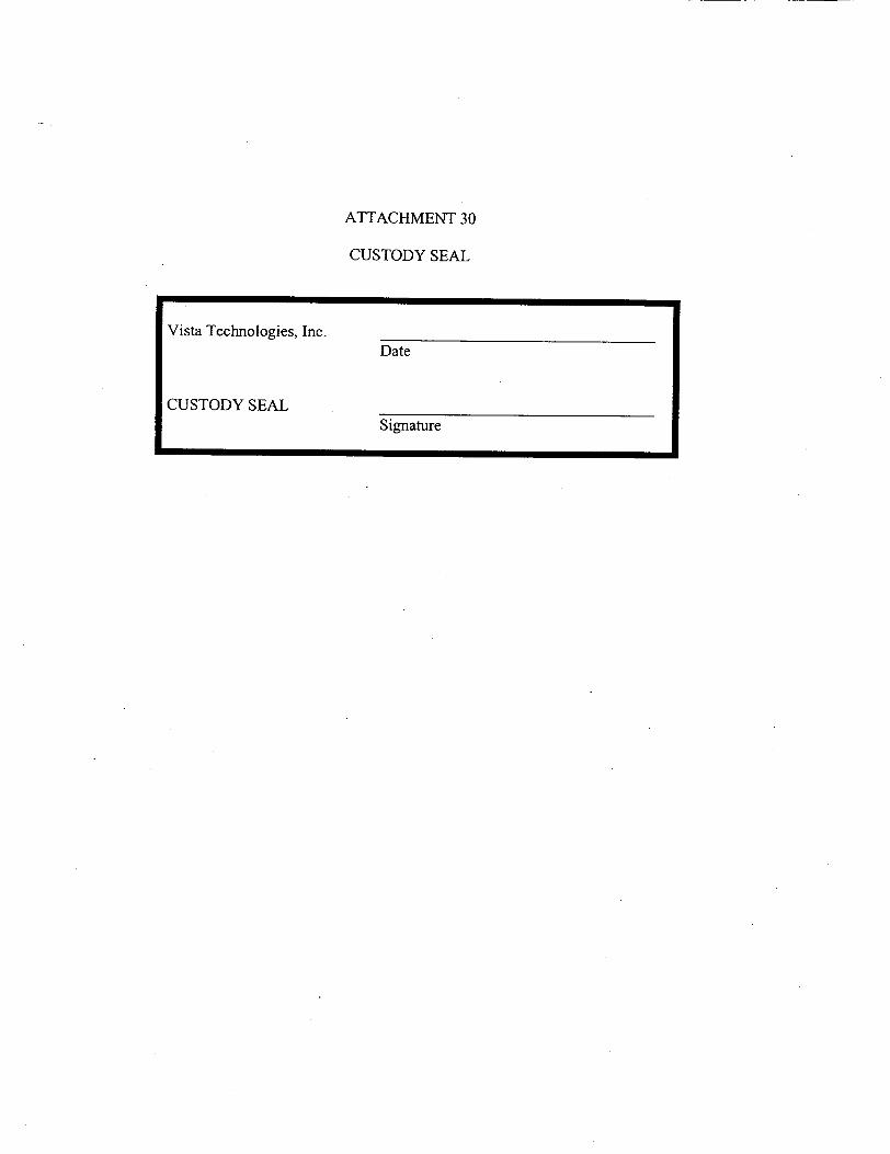
ATTACHMENT 30
CUSTODY SEAL
Vista Technologies, Inc. Date
CUSTODY SEAL Signature