Virtual Cut-Through: A New Computer Communication ... Cut-through...Virtual Cut-Through: A New...
20
Virtual Cut-Through: A New Computer Communication SwitchingTechnique Parviz Kermani and Leonard Kleinrock Computer Science Department, University of California, Los Angeles, Los Angeles, California 90024, USA In this paper a new switching technique called virtual cut-through is proposed and its performance is analyzed. This switching system is very similar to message switching, with the difference that when a message arrives in an intermediate node and its selected outgoing channel is free (just after the reception of the header), then, in contrast to message switching, the message is sent out to the adjacent node towards its destination before it is received completely at the node; only if the message is blocked due to a busy output channel is a message buffered in an intermediate node. Therefore, the delay due to unnecessary buffering in front of an idle channel is avoided. We analyze and compare the performance of this new switching technique with that of mes- sage switching with respect to three measures: network delay, traffic gain and buffer storage requirement. Our analysis shows that cut-through switching is superior (and at worst identical) to message switching with respect to the above three performance measures. Leonard Kleinrock is Professor of Computer Science at the University of California, Los Angeles. He received his B.E.E. at the City College of New York in 1957 and his M.S.E.E. and Ph.D.E.E. at the Massachusetts Institute of Technology in 1959 and 1963 respectively. In 1963 he joined the faculty of the School of Engineering and Applied Science at the Univer- sity of California, Los Angeles. His research spans the fields of computer networks, computer systems modeling and anal- ysis, queueing theory and resource sharing and allocation in general. At UCLA, he directs a large group in advanced tele- * This research was supported by the Advanced Research processing systems and computer networks. He serves as con- Projects Agency of the Department of Defense under con- sultant for many domestic and foreign corporations and tract MDA 903-77-(3-0272. governments and he is a referee for numerous scholarly publi- cations and a book reviewer for several publisher~. He was awarded a Guggenheim Fellowship for 1971-1972 and is an IEEE Fellow "for contributions in computer-communication © North-Holland Publishing Company networks, queueing theory, timeshared systems, and engi- Computer Networks 3 (1979) 267-286 neering education", 267
Transcript of Virtual Cut-Through: A New Computer Communication ... Cut-through...Virtual Cut-Through: A New...

Virtual Cut-Through: A New Computer Communication Switching Technique
Parviz Kermani and Leonard Kleinrock Computer Science Department, University o f California, Los Angeles, Los Angeles, California 90024, USA
In this paper a new switching technique called virtual cut-through is proposed and its performance is analyzed. This switching system is very similar to message switching, with the difference that when a message arrives in an intermediate node and its selected outgoing channel is free (just after the reception of the header), then, in contrast to message switching, the message is sent out to the adjacent node towards its destination before it is received completely at the node; only if the message is blocked due to a busy output channel is a message buffered in an intermediate node. Therefore, the delay due to unnecessary buffering in front of an idle channel is avoided. We analyze and compare the performance of this new switching technique with that of mes- sage switching with respect to three measures: network delay, traffic gain and buffer storage requirement. Our analysis shows that cut-through switching is superior (and at worst identical) to message switching with respect to the above three performance measures.
Leonard Kleinrock is Professor of Computer Science at the University of California, Los Angeles. He received his B.E.E. at the City College of New York in 1957 and his M.S.E.E. and Ph.D.E.E. at the Massachusetts Institute of Technology in 1959 and 1963 respectively. In 1963 he joined the faculty of the School of Engineering and Applied Science at the Univer- sity of California, Los Angeles. His research spans the fields of computer networks, computer systems modeling and anal- ysis, queueing theory and resource sharing and allocation in general. At UCLA, he directs a large group in advanced tele-
* This research was supported by the Advanced Research processing systems and computer networks. He serves as con- Projects Agency of the Department of Defense under con- sultant for many domestic and foreign corporations and tract MDA 903-77-(3-0272. governments and he is a referee for numerous scholarly publi-
cations and a book reviewer for several publisher~. He was awarded a Guggenheim Fellowship for 1971-1972 and is an IEEE Fellow "for contributions in computer-communication
© North-Holland Publishing Company networks, queueing theory, timeshared systems, and engi- Computer Networks 3 (1979) 267-286 neering education",
267

268 P. Kermani, L. Kleinrock / "Virtual cut-through"
1. Introduction
One of the basic problems in a computer communication network design is to select the switching method. Early computer networks were built over the existing telephone networks using principles of telephone switching, namely line (circuit) switching. With circuit switching, a complete path of communication links must be set up between two parties before the real communication begins. This set up is accomplished via a signalling message. The path is tied up during the entire session between the two parties. This includes the set up time plus any idle periods during which the parties are silent. Once a path is set up, no further signalling for addressing purposes is necessary; thus, in a circuit switched network, a path, once set up, implicitly provides all the addrsssing informa- tion.
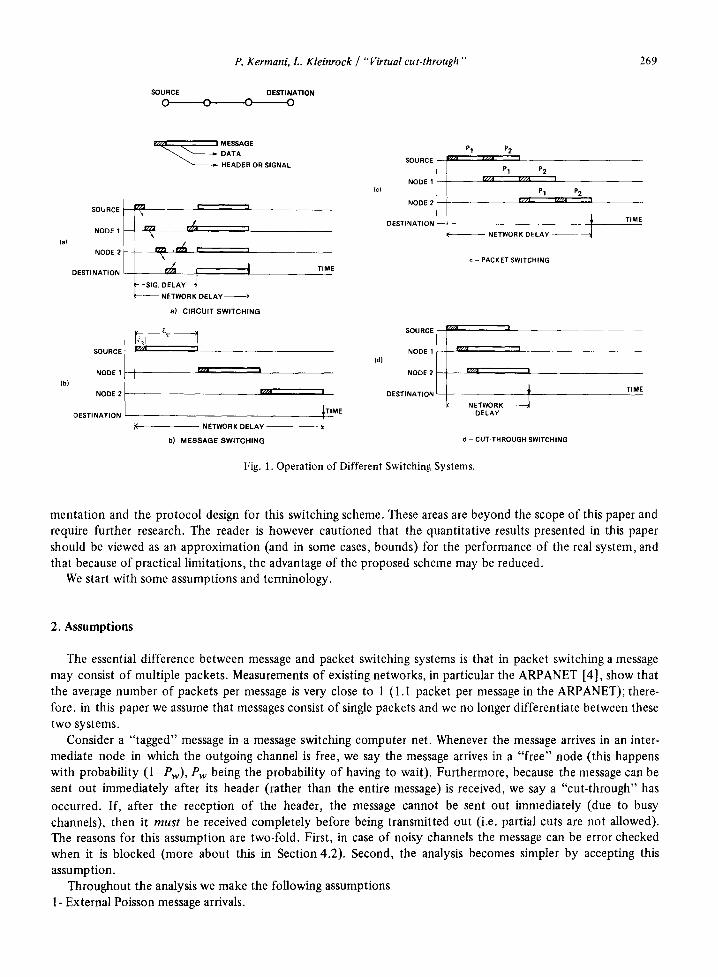
When applied to data communication networks, circuit switching suffers from some drawbacks. One is the slow path set up which delays transfer of messages from sender to receiver. Circuit switching was originally used in telephone networks designed for human communication. A telephone conversation is typically an order of magnitude longer than the signalling delay. On the other hand, measurement studies [1] and [2] conducted on time sharing systems indicate that computer communication data streams are bursty. That is, they consists of frequent short messages with occasional long ones. If the circuit is released after each message, then the excessive signalling delay, especially for short messages, is a serious disadvantage of this switching technique. Another draw- back is the low channel utilization due to the fact that the channels on a path are tied up but actually are not being used during the idle periods. That is, the dynamic assignment of paths is not dynamic enough. Fig. la shows the network delay in a circuit switched system. It is assumed that there is no interfering traffic and that the number of intermediate nodes in the path is 2.
In order to achieve a better channel utilization, one may think of relinguishing the channels on a path during periods in which the parties are silent. This brings us to the idea of(store-and forward) message switching. In this method messages are routed toward their destination node without establishing a path beforehand; rather, the paths are assigned dynamically. Through provision of a storage facility at each node, message are stored in inter- mediate nodes and then are sent forward to a selected adjacent node (hence the name store-and-forward). This selection is made by a well-defined decision rule referred to as the routing algorithm. The process is repeated until the message reaches the destination node. By attaching addressing bits to the header, each message carries information regarding its destination. Since we do not allocate communication links into complete paths for specific source-destination pairs of nodes, each link is statistically shared by many nodes. Fig. Ib shows the net- work delay in a message switching system.
Examination of Fig. lb suggests that a better utilization and further reduction in network delay is possible by dividing a message into smaller pieces called packets. This method is called packet switching and is shown in Fig. 1 c. In packet switching, each packet (instead of a message) carries its own addressing information. This intro- duces extra overhead; however, by dividing messages into packets, a message can use a number of links on a path simultaneously. This allows more complete resource sharing (here the resource is the communication link), a higher channel utilization and lower net delay [3].
From Fig. lb and lc we observe that the extra delay is incurred because we do not permit a message (or packet) to be transmitted out of a node before it is received completely. We not that when a message arrives in an intermediate node and its outgoing channel is free, it actually does not need to be completely received in the node before being transmitted out. In fact, it can be transmitted out immediately after the outgoing channel is identi- fied, i.e., after the reception of the message header and the selection of outgoing channel by the routing proce- dure. That is, we need only buffer when we encounter a busy channel, but we may avoid the delay due to unnecessary buffering in front of an idle channel. This is essentially a hybrid mixture of circuit switching and packet switching techniques. Fig. ld shows the delay when this "virtual cut-through" method is used. If the packet encounters busy channels at all of the intermediate nodes, the outcome is exactly the same as in packet switched network. On the other hand, if all of the intermediate channels are free, the outcome is similar to a circuit switched system. Cut-through switching is most advantageous when the network load is low.
In this paper we study and analyze the performance of this virtual cut-through switching technique and com- pare it with message switching. The development of the analytical models is based on a number of simplifying assumptions. Unless it is necessary for the development of the models, we avoid discussing the physical imple-
SOURCE o
P. Kermani, L. Kleinrock / "Virtual cut-through"
DESTINATION o o o
269
(al
(b)
v..~ , MESSAGE ~ , ~ = DATA
HEADER OR SIGNAL
SOURCE - - ~ I I
NODE 1 r/~'A I
NODE 2 ~ I I
DESTINATION I ~ I I ~-~- SIG. DELAY~ . ' - - - - NETWORK DELAY
a) CIRCUIT SWITCHING
2222 t - 2 NODE 2
DESTINATION
TIME
r//A I
NETWORK DELAY I TM b) MESSAGE SWITCHING
(c)
P1 P2 i - i SOURCE I ~ "~ ,,,A !
P1 P2 NODE 1 ~/A r//A I
~ _ P1 P2 NODE 2 r,/, ~/IA
DESTINATION ~ . . . . ~ TIME i ( NETWORK DELAY -
C - PACKET SWITCHING
(d)
SOURCE i~'i !
N O D E I ~ ~ H [ / H j I
NODE2 rz//J 1
DESTINATION l TIME I~ - -NETWORK-- - - -
DELAY
d - CUT-THROUGH SWITCHING
Fig. 1. Operation of Different Switching Systems.
mentation and the protocol design for this switching scheme. These areas are beyond the scope of this paper and require further research. The reader is however cautioned that the quantitative results presented in this paper should be viewed as an approximation (and in some cases, bounds) for the performance of the real system, and that because of practical limitations, the advantage of the proposed scheme may be reduced.
We start with some assumptions and terminology.
2. Assumptions
The essential difference between message and packet switching systems is that in packet switching a message may consist of multiple packets. Measurements of existing networks, in particular the ARPANET [4], show that the average number of packets per message is very close to 1 (1.1 packet per message in the ARPANET); there- fore, in this paper we assume that messages consist of single packets and we no longer differentiate between these two systems.
Consider a "tagged" message in a message switching computer net. Whenever the message arrives in an inter- mediate node in which the outgoing channel is free, we say the message arrives in a "free" node (this happens with probability (1-Pw), Pw being the probability of having to wait). Furthermore, because the message can be sent out immediately after its header (rather than the entire message) is received, we say a "cut-through" has occurred. If, after the reception of the header, the message cannot be sent out immediately (due to busy channels), then it must be received completely before being transmitted out (i.e. partial cuts are not allowed). The reasons for this assumption are two-fold. First, in case of noisy channels the message can be error checked when it is blocked (more about this in Section 4.2). Second, the analysis becomes simpler by accepting this assumption.
Throughout the analysis we make the following assumptions 1- External Poisson message arrivals.
270 P. Kermani, L. Kleinrock / "Virtual cut-through"
2- Exponentially distributed message lengths. 3- Infinite nodal capacity. 4- Deterministic routing. 5- Independence assumption [5]. 6- Balanced network (defined below). 7- Negligible Propagation delay.
Definition A network is said to be balanced if the utilization factor of all of its channels is the same. Note that this
property does not imply any assumption on the topology of the network. Assumptions 1 and 2 assign specific distributions to message arrivals and lengths *. Measurement studies [1 ]
on multi-access computer systems justify these assumptions to some extent. In accepting Assumption 2 we are faced with a further implication which is raised by the fact that we will assume each message can fit in a buffer of a constant length. We delay discussion of this limitation until Section 7. Nodal storage limitation can cause block- ing, and consequently retransmissions, or loss of messages, hence an increase in delay or a decrease in throughput [6]. It is generally accepted [7], [8], that with a reasonable storage size the above assumption is fairly accurate. Most store-and-forward networks employ a variant of adaptive routing schemes, consequently, the validity of assumption 4 depends critically on the difference of behavior between deterministic and adaptice techniques. Fultz [9] has found that with a proper deterministic routing scheme (e.g., shortest path, etc.) the delay perform- ance of both routing schemes are in close agreement. The implications imposed by the independence assumption are thoroughly discussed in [5]. In short, this assumption is quite acceptable as long as the network does not con- tain long chains with no interfering traffic. We use Assumption 6 as a means to avoid complexity in our analysis and while we have not made specific assumptions regarding the topology of the network, there are certain topologies (e.g., grid or toms [6]) in which this assumption is easily realizable. For a more detailed discussion regarding implications of the above assumptions, the interested reader is referred to [5] and [6].
The implications and limitations imposed by these assumptions will affect our analysis of both the cut-through as well as the message switching systems. Considering the fact that in our study we mainly compare the performance of these two switching systems with each other, and that these assumptions affect the two schemes equally, the comparison results should be reasonable and close to reality.
The analysis is carried out for multiple channel links. We use the word link for the communication media between nodes. A link of capacity C can be split into NchC~l) channels, each of capacity CINch.
3. Analysis of the Number of Cut-throughs
Although the average number of cut-throughs is not a good measure of performance, it is a quantity needed in the evaluation of the network delay. In this section we investigate some of its properties.
Theorem I The average number and the generating function of the number of cut-throughs in a balanced network with
channel utilization p are given by
ne = (nh - 1)(1 -Pw) (1)
and
N[Pw + z(1 -Pw)] (2) Co(z)= e w + z ( l _ P w )
where ~c is the average number of cut-throughs, ~h is the average number of hops (or path length), Pw is the
* The assumption is that a message consists of data bits and a header. The header is used, among other things, for addressing purposes.
P. Kermani, L. Kleinrock / "Virtual cut-through" 2 71
probability of waiting at an arbitrary channel (no cut), Cp(.) is the generating function of the number of cut- throughs when the utilization factor of the network channels is p and N[.] is the generating function of the number of hops.
Proof'." Appendix 1.
to For the special case of single channel links, Pw = P, the utilization of channels, and so Eqs. (1) and (2) reduce
fie = (fib -- 1)(1 -- p) (3)
W[p + z(1 - o ) ] C ° ( z ) - p + z ( 1 - p ) (4)
These equations show that when the average number of hops (fib) increases, so does the average number of cut-throughs. This is intuitively clear since, as the number of intermediate nodes increases, there is a greater chance to experience more cuts. They also show that if c is a decreasing function of p which means that in a less crowded network the average number of cuts is larger.
Special Cases
(t) p = 1
(II) p=O This implies Pw = 1 and tic = 0, i.e., no cut-throughs are made. This implies Pw = 0 and nc = nh -- 1.
In case (I), with probability one, all of the intermediate nodes are busy upon arrival of the message. The network then behaves like a pure message switched system. In (II), with probability one, all of the intermediate nodes are free and all of them are cut through; thus it resembles a circuit switched system. Later in this paper we show performance curves for the system.
4. Delay Analysis
An important performance measure for a computer communication net is the average source to destination message delay T, defined below:
T= ~ T q _
• . - - Z q t , l ~"
where 7ih is the average number of messages entering the network per second with origin i and destination/, 7 is the total arrival rate of messages from external sources, and Zq is the average message delay for messages with origin i and destination/.
For a message switched system a straight forward application of the Little's result [10] to the queueing model leads to the following expression for the average network delay, [5]. (Here we use the symbol Tm to indicate that this delay is for message switching systems).
T,,, --- X;
i 7
where Ti and ?ti are the average delay and the traffic rate on channel i, respectively. Calculation of T i is, in general, a nontrivial and currently unachieved task; however, by accepting the assump-
tions of Section 2, especially the independence assumption of Kleinrock [5], we are in a position to reduce the network of queues model to the model first studied by Jackson [ 11 ]. By virtue of his results, each node behaves stochastically independent of the other nodes and similar to an M/M/m system, for which the average delay is

212 P. Kermani, L. Kleinrock / “Virtual cut-through ”
known [ 121. For the special case of uniform p all of the nodal delays are identical and we have
Tm=Ti q:
In [.5] it is shown that Ci Xi/y = nh, So we get
Tn, = G,,Ti (3
So far we have not made any assumption regarding channel error rate. We will initially give an analysis of delay
for a network with noiseless channels. It turns out that for such a system the analysis is fairly simple and a closed form expression for network delay is obtainable. However, when the network contains noisy channels, as we will
see shortly, the network delay can be calculated through a fairly complicated iterative routine. We will present a delay analysis of these two systems; however, later WC deal only with networks with noiseless channels.
4.1, Delay Analysis for a Network with Noiseless Channels
When channels are error free, each nodal delay becomes similar to the system delay of an M/M/m queueing
system. So we have
TizN,h+-‘??_ PC ,Q - P)
and
(6)
where Nch is the number of channels per link, l/p is the average message length, and C is the total capacity of the link (notice that capacity of each channel is C/NC,,). For the special case of Nch = 1 we get
For the average network delay in the cut-through system we have the following result:
Theorem 2
The average network delay in the cut-through system is given by
T,==T,,,-(n,- l)(l -P,)(l -a)t, (7)
where t,(=l/yC) is the average transmission time of a message on a channel, t/, is the average transmission time of
a header and a = t/,/t,,, < 1 (note that a header is part of a message).
Proof: Appendix 2.
For the special case of Nch = 1 and (Y = 0, we have T, = Eht,/( 1 - p) and P, = p and Eq. (7) reduces to
T, = z - (& - 1)(1 -p) 1,
From Eq. (7) we have
(tih - l)(l -cY)tm forp=O T,,, - T,=
0 forp= 1
(8)
(9)
which shows that if all of the intermediate nodes are busy (p = 1 and P, = l), no reduction in delay is made. On
the other hand, when p = 0 and there is no intermediate busy node, the transmission times of the intermediate

P. Kermani, L. Kleinrock / "Virtual cut-through" 273
channels are saved. This fact becomes clear when we set a --- 0. For a = 1 Eq. (7) gives T c = T,n ; this is intuitively clear because a = 1 implies that a message is completely composed of its header and the cut-through system is identical to message switching.
4.2. Delay Analysis for a Network with Noisy Channels
A detailed analysis of a network with noisy channels is very complicated. The difficulty is that in a network with unreliable channels there must be some combination of acknowledgment and timeout mechanisms to guarantee correct delivery o f messages; modeling of such mechanisms is usually an involved task [13], [14] and [ 15]. In this paper we accept a very simplified model for this mechanism. For message switching we assume if a message is received with some bits in error (which we assume happens with a constant probability Pe), it is retransmitted immediately (i.e. instantaneous negative and positive acknowledgment). We further assume that with retransmission traffic, the network is still balanced (Definition 1).
I f the average delay for one pass transmission is ~-, the total nodal delay becomes
(Nch ew ) Ti= ~ = \ t~C +/JC(1 - P e ) /(1 - Pe)
and the network delay for message switching will be
Tm=~Nch+ Pw ) \ktC pC(1---Pe) fib~(1-Pe) (10)
In the above expression Pe is the effective network traffic. The useful traffic is given by
p = ( 1 -Pe) Pe (11)
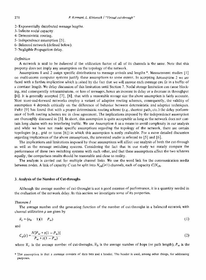
For the cut-through system the operation is somewhat more involved. We assume that a message is error checked only in its destination node or any intermediate node which it cannot cut through; we call this type of node a final node (which is not necessarily the same as the destination node although the destination node is always a final node). It is not that a message cannot be checked for error in an intermediate node through which it makes a cut, but even if it is recognized that a message contains some bits in error (this can be done only after the last bit of a message arrives in a node), the message has already started its transmission out of the node and there is no way to stop the transmission and to notify the next node(s) not to accept the message. In a final node, because the message is received completely, error checking (and stopping) can be done. If it is recognized that the message is erroneous, it has to be retransmitted through all of the intermediate nodes (including the first node on the cut-through path). As before, we further assume that acknowledgments (positive and/or negative) are instantaneous. Fig. 2 makes these operations clear. In this figure a message is to be transmitted from source node S to destination node D. The message has already made its way to an intermediate node i (in which it has been blocked). When it starts transmission from this node, it makes cuts through nodes i + 1, i + 2 and i + 3 and is again blocked at node i + 4. At this node, however, after error checking, the message is found to have some bits in error. Through a negative acknowledgment (which we assume is instantaneous), it is retransmitted from node i. In the retransmission process, however, it can make a cut only through node i + 1 and is blocked at node i + 2. Depending on whether it is received incorrectly or not, further retransmission from node i is necessary or it can start making its way toward its destination node D (after queueing delay) *.
The delay analysis for the cut-through system in a network with noisy channels is fairly complicated and in fact no closed form expression for it has been derived. The conditional delay, when the number of hops is constant (nh = n) is given below.
* Note that in cut-through switching a header should carry information regarding not only the source-destination, but also the last node in which the message was blocked (the last final node). This results in a larger header length for cut-through switching than message switching. We will ignore this fact in our analysis in order not to make the derivations complex. The reader is however cautioned that the performance of the cut-through system will be lower than what is predicted by our model.

274 P. Kermani, L. Kleinrock / "Virtual cut-through"
SOURCE
0 /~
FIRST TRANSMISSION
~ 0~~ 0 ./¢DESTINATIONo FIRST RETRANSMISSION
S i i+I i+2 i+3 i+4 i+5 D
Fig. 2. Example of Rctransmission in the Cut-Through System.
Theorem 3 The average network delay for the cut-through system in a network with noisy channels is given by
T~ : ~ " ) ( . )
where
(12)
] - 1
. . . . ~ {~ck)(i , /)+ ~ci-k+l)(l](1 pe)k+l + ~c])(])[l (1 Pe)k+' ]}pe~(i) (k) ( i>]>O) k=O
(13)
and
and
] - - l
[T~cck)(i,/') + T~c]-k+ l)( i)(l _ pe)k+ 1] pc~)(k ) ~J~(i) - k=o
] -1 (1 -- Pe) k+ 1p(ci)(k )
k=O
( i : j > 0)
=0 (/= 0)
Nch Pw IE[~]+ktn =--~-+ ~ - - .+k th I I -tL I'~( 1 -- Pe)
J)
| pC uC(1 -pe)
(i = j)
÷ kth (i > ])
(14)
(1 -Pw)kPw ( 0 ~ < k < ] - 1 a n d ] > l) (15)
POc)(k) = (1 Pw) k ( k = ] - 1)
where ~" and ~ are the service thne and the waiting time in a node, respectively, Pe is the effective traffic and n is the path length.
For a proof of this theorem the interested reader is referred to [14]. If we set Pe = 0, after some algebra Eq.(12) reduces to Eq. (7), the delay for the cut-through system in a net-
work with noiseless channels. The useful traffic is related to effective traffic according to the following theorem.
Theorem 4 For an n-hop cut-through system in a balanced network with noisy channels, the useful traffic p is determined
according to the following relationships
n p = N--~-~ p~ (16)

P. Kermani, L. Kleinrock / "Virtual cut-through" 275
where
Nt(n ) -'-
n - l i [ (k+ 1)+ Xt(n - k - 1)(1 - P e ) k+l] P(en)(k)
k=o
n - - 1
(1 - Pe) k+ 'P(cn)(k) k=O
(n > 0)
0 (n = O) (17)
where P(cJ)(k) is given by Eq. (15). Nt(n) is the total number of times a message is transmitted when the path length is n; note that Nt(n ) >~ n.
For a proof of this theorem the reader is referred to [ 14]. Let us consider some special cases of interest
1- If Pw ~ 1 then it can be shown that Eqs. (10) and (12) become identical. This is intuitively clear as in this case ~c = 0 and retransmissions take place only over one hop in both systems.
11- If n = 1, again Eqs. ( I0) and (12) become identical (on a one-hop path there cannot be any cut-throughs!). III- If Pe = 0 then both Eqs. (11) and (16) reduce to p = Pe. Clearly, in this case there is no retransmission and the
effective traffic is the same as the useful traffic. In Section 6 we present some performance curves which show the effect of channel errors on network
performance, with the exception of these cases, we assume that network channels are noiseless in the remainder of this paper.
5. Traffic Gain
Analysis o f Eq. (7) shows that
T m ( p ) - Tc(p)~O O < p < l
(here we use Tin(p) and Tc(p) to indicate the delay at a given traffic load, p). Below, we present performance curves which explicitly show this fact. This property indicates that at the same traffic level the network delay in a cut-through system is less than in message switching. Equivalently, for the same network delay the cut-through system can handle more traffic; see the sketch Fig. 3 in which Pm and Pc are defined as the throughput carried by message switching and cut-through switching, respectively, at a constant network delay. In this section we calculate the throughput increase (Pc -Pro). (Actually, what we find is the difference between channel utiliza-
OEL?~ ,m~,
UTILIZATION
Fig. 3. Sketch of Traffic Gain in the Cut-Through System.

276 P. Kermani, L. Kleinrock / "Virtual cut-through"
tion of the two systems at the same delay; this gives us a measure of traffic gain). Setting Tin(Pro) = Tc(Pe) we get the condition
~h(N~ ÷ Pwm ]_- [Nch Pwc ) \ IAC IdC6 ~ Pm) ] - n h t - ~ + IdC(i 7~ t9e) -- (nh -- 1)(1 - Pwc)( l - ~) Uc~pc (18)
where Pwm or Pwc are the waiting probabilities at a node for which the utilization factor is Pm or Pc, respectively (recall that we are assuming noiseless channels).
For Nch > 1, Pw is a complicated expression of p and Nch and it is not possible to find Pc in terms of Pm explicitly. For this reason we solve Eq. (18) analytically only for the case where Nch = 1. For higher values of Nch numberical evaluation techniques are necessary. For Neh = 1 we have Pw = P and Eq. (18) reduces to
1 - Pc 1 - p . , = 1 - n ( l - p J ( 1 - a )
where 7? = (fib - 1)/fih, 0 ~<r/< 1. From the previous equation we obtain the throughput to be
1 + 277(1 - a ) ( 1 - p r o ) 2 - [1 + 477(1 - ~ ) ( 1 - pm) 2] 1/2 Pc - P m = 2r/(1 - a)(1 - Pro) (19)
When fij, = 1 (r? = 0), then Pc = Pro; i.e., there is no gain. This is the case for a fully connected net. Forf ih-+ oo(r/-+ 1) we have
lira (Pc Pro) = l + 2 ( l - a ) ( 1 - p m ) 2 - [ l + 4 ( 1 - a ) ( 1 - P m ) 2 l in - ( 2 0 )
~,-~o 2(l - ~)(1 - Pm)
Note that when -n h -+ ~o, Tm and Tc both grow to infinity; however, in the limit, there is still a throughput gain in using the cut-through system.
6. Some Performance Curves and Simulation Results
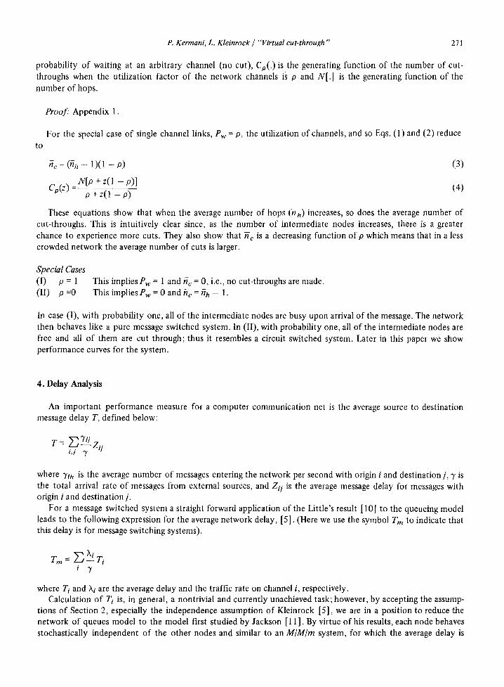
Fig. 5 shows the number of cuts as a function of p, the channel utilization as given in Eq. (1). The network configuration and traffic pattern is shown in Fig. 4. This is a tandem queue in which, except for the first and the last 2 nodes, traffic passes through 3 hops (2 internediate nodes). The reason for selecting this topology was to create a uniform traffic load on each channel. For a single channel system nc is a linear function of p. Fig. 5 also shows some simulation results on this tandem queue model for Nch = 1, 2, and 4. In the simulation program we used all the assumptions of Section 2, but we assumed the message lengths to be of constant length (instead of exponentially distributed), and also did not use the independence assumption. As our analytic model predicts, when the traffic is light (p ~ 0), the average number of cuts is equal to (-nh -- 1) which is 1.6 for our network; whereas, for a heavily loaded system (p ~ 1) the average number of cuts becomes zero. In spite of the differences between the underlying assumptions o f the analytic and the simulation model, the match between the simulated and the analytic results is very encouraging.
Figs. 6a to 6c show the normalized delay curves (pCTc) as a function of useful channel traffic. Recall that throughput is not necessarily equal to the effective channel traffic; they are related to each other according to
R" h = 2 . 7 1
~ 1 ~ = 20 m r ~ . pC a - o . 1
Fig. 4. The Simulated Tandem Queues.

P. Kermani, L. Kleinrock / "Virtual cut-through" 277
R h = 2.71
! Nch = 1 SIMULATION RESULTS Nch = 2
Nch =4
ANALYTIC RESULTS
1.6
1.2
0 . 8
Z
0 . 4
O
Nch =20
15
10
4
~ 2 /k
1
i i i , i i ~ J
0 . 2 0.4 0.6 0.8 1.0
UTILIZATION
Fig. 5. Average Number of Cut-Throughs.
Eqs. (1 1) and (16). The curves shown are for a number of cuts equal to 3 and for different values of a(=th/tm)and Pe (channel error rate). Although channel error rate affects performance of both message switching and the cut-through system, it is interesting to note that this parameter has a more serious effect in the cut-through system than in the message switching system. In fact for a very noisy channel (large Pe) the performance of message switching may become better than the cut-through system (for the parameters of these graphs this happens approximately when Pe > 0.4). The reason for this phenomenon is that in the cut-through system, if a retransmission becomes necessary, it must take place over more than one hop; Eq. (16) makes this fact clear. Fig. 6c shows this effect is addition to a rather interesting phenomenon. Here the channel error rate is (unreason- ably) high, Pe = 0.45. When traffic is low the chance of making many cut-throughs is high, but the received messages therefore have a greater chance of having bits in error; thus the retransmission overhead and hence the delay is high. As traffic increases, althoug the cut-through properties are less effective, we are saved unnecessary long retransmissions and the network delay decreases. Further increase in traffic results in higher delay due to queueing phenomena.
Perhaps a better comparison is to find the ratio Tc/Tm. We have
T c h h - 1 (1 - Pw)(1 - a)Nch - 1 ( 2 1 )
Tm ~h Nc~ + P w / ( 1 - P)
This ratio is shown in Figs. 7a to 7c. We see from Eq. (21) and from Fig. 7a that when c~ = O,Nch = 1 and p = 0 then Tm is ~h times larger than Tc. This is intuitively clear since, in the cut-through system, messages can snake through all of the intermediate nodes without experiencing any delay (recall that a = 0); however, in message switching the delay incurred at each intermediate node is tin, the transmission time of a message over a single channel. As the channel utilization (or the normalized throughput) approaches 1, cut-through switching and message switching delay become identical (see also Figs. 5 and 6).
Some limiting cases Let us study the limiting value of Tc/Tm as a function of the variables a, fih and Nch(O <<-a <~ 1, 1 <~fih,
1 ~ Arch). When ~h = 1 (i.e. in a fully connected net), then, as we expect, Te/Tm = 1 for all possible values of p, the utili-

278 P. Kermani, L. Kleinrock / "Virtual cut.through"
20
12
=~ o
8
0 ~ 0
. . . . CUT-THROUGH
Nch = 6 J
a ~
Nch =
~ / ; - / /
0.2 0.4 0.6 0.8
NORMALIZED THROUGHPUT (~//aC}
1.0
MESSAGE SWITCHING
Nch = 6 J
16 4 - -
~ 2
/ ~ Nch =
I / / " " \ ' ~ - 2
. . . . . ..55,5-" 1
0 ' 0 0 2 0.4 0.6 0.8
NORMALIZEDTHROUGHPUT ( ~ C )
1.0
Fig. 6a. Delay vs. Throughput. Fig. 6b. Delay vs. Throughput.
24 r ~ MESSAGE SWITCHING
. . . . . . CUT-THROUGH
Nch =
16
N
0 • 0 0.2 0.4 0.6 0.8
NORMALIZEDTHROUGHPUT
Fig. 6c. Delay vs. Throughput
1.0

P. Kermani, L. Kleinrock / "Virtual cut-through "' 279
nh ; 1 2
o..t
0.6
~= o~o Pe = 0.0
O.4
0.2
0 0 0.2 0.8 0.4 0.6 NORMAL IZED THROUGHPUT
1.0
0.8
O.6
J
0.4
0.8 0.6
- ~ 0.1
~h = 5
Nch = 1
oi~ oi, DiE olB NORMAL IZED THROUGHPUT
l-'ig. 7a. Ratio of the Delay in the Two Switching Systems Fig. 7b. Ratio of the Delay in the Two Switching Systems.
J
0.4
J
/
/
J
/ I Nch =i
1 '! 2 1
_ - - 16
a=o .1
Pe = 0.0
0.2 0.4 0.6 0.8 1.0
NORMAL IZEDTHROUGHPUT
Fig. 7c. Ratio of the Delay in the Two Switching Systems.
zation, as shown in Fig. 7a. For nh ~ '~ the ratio becomes
Tc (1 - P w ) ( 1 - a ) Nch lira = 1 - - ( 2 2 )
~ h ~ ~ Nch + Pw/(1 - P)
The interesting point is that, even though Tc and Tm both become unbounded as ~h ~ 0% their ratio has a well defined limit. In fact Eq. (21) shows that Tc/Tm is a strictly decreasing function ofn'h; the longer the path length, the more advantageous is cut-through.
Looking at the dependency of Tc/T m on c~, it is no surprise that Eq. (21) shows that smaller values of a result in a better performance. In fact for a = 1, both system are identical; this behavior is shown in Fig. 7b.
The dependency of Tc/T m on Arch is shown in Fig. 7c. As expected, we see that larger values of Ncn result in a lower value o f Tc/Tm.
Some simulation results for the throughput-delay performance are shown in Fig. 8. The simulated network is once again the tandem queue system shown in Fig. 4. The discrepancy between the simulated and the calculated values o f T c and Trn is the result of the topology of the network and the message length distribution. The analytic

280 P. Kermani, L. Kleinrock / "Virtual cut.through"
2 4 ,
16
I -
D = N J
g Z
8
CUT - THROUGH
II~zC 20 msec C~=1
n h = 2.71
S IMULAT ION:
• Nch = 4
• Nch = 2
ONch= l
Nch
0 1 - 0.0 0.2 0.4 0,6 0.8 1,0
NORMAL IZED THROUGHPUT (~./u C)
Fig. 8. Some Simulation Results.
results are for exponentially distributed message lengths, whereas in the simulation program we have used fixed length messages.
The traffic gain is shown in Fig. 9; The curves are for single channel links (Eq. (19)). This figure shows that at the same network delay, cut-through switching can carry more traffic than message switching, and that the difference is higher when the network is lightly loaded.
The curves show that higher values o f n h or smaller values ofc~ result in a better gain. For ~a = 1 or a = 1 both systems behave identically.
i
0,2
o,I ! Nch = 1 a =0.1
Po=O.O
~ 2
0 ' - ( ' 0.2 0.4 0.6 0,8
Pm
Fig. 9. Traffic Gain.

P. Kermani, L. Kleinrock / "Virtual cut-through" 281
7. Storage Requirements
In a store-and-forward message switching system, buffer storage is provided at the switching nodes. Although the cost of storage is decreasing, it nevertheless is an important component of the overall network cost. The pur- pose of this section is to calculate the storage requirements for the cut-through system and compare it with the requirements of the message switching system. Throughout this section we deal with noiseless channels. We start with some assumptions regarding buffer allocation in the two systems.
7.1. Buffer Allocation in Message Switching
Storage is divided into buffers of equal size which can accommodate a message of maximum length. Each buffer can be used by only one message at a time, even though such a message may not fill its entire buffer. Within a node, a message is never allocated more than one buffer. With this buffer management, one might think that the assumption of exponentially distributed message length should be replaced with a truncated exponential distribution. However, measurements of the existing networks, expecially the ARPANET [4], show that the average message length is a small fraction of the maximum packet length (250 bit average compared to 1000 bit maximum for the ARPANET). In such cases where the average message length is much smaller than the buffer size, we find that the exponential message length assumption is not unreasonable. Regarding the messages which are being transmitted, we assume that when the first bit of a message arrives in a node, a full buffer is imme- diately allocated to the message. This means that all messages in transmission use two buffers simultaneously (one in the node transmitting and one in the mode receiving). We assume that acknowledgment is instantaneous. As a result, the moment a message is completely received at a node, its source buffer is relinquished.
7.2. Buffer Allocation in Cut-Through Switching
There are two types of buffers in this system: message buffers and header buffers (with lengths lm and lh, respectively). A header buffer is used by a message when it cuts through a node. The buffer is allocated when the first bit of a message arrives at a node. After the reception of the message header, if it is recognized that the selected outgoing channel is free, no further storage is allocated to this message and it starts being transmitted out (however, this header buffer is used while the message is snaking through the node). If, however, the outgoing channel is busy, then the message must be completely received in the node and (the remainder of) a message buffer is allocated to it (this happens at a final node, i.e. the destination node or any intermediate node where a cut is not possible). We note that a message may be using a number of header buffers simultaneously, but it can use at most two message buffers at one time. Regarding the acknowledgment, we assume that a copy of a message is kept at the source node, or at any intermediate node in which it is blocked (i.e. through which it cannot make a cut), until it is completely received at a succeeding final node. If this final node is the destination node then, after completion of transmission out of the network, both message buffers are released simultaneously. If, however, this final node is not the destination node then a copy of the message is kept in this final node and the preceding message buffer is released (i.e. after reception of the first acknowledgment, the copy of the message at the source node is dropped and its buffer is released).
7.3. Storage Requirement: Results
Let S-m be the expected value of the total amount of storage required at a node in message switching and let ,~c be the same quantity for the cut-through system. As before, we use lm and lh for message buffer and header buffer size. We also assume that
th _ lh header buffer size Og~
tm Im message buffer size
For storage requirements in the message switching and the cut-through switching systems we have the follow- ing theorem.

282 P. Kermani, L. Kleinrock / "Virtual cut-through"
Theorem 5 The expected amount of storage required at a node in message switching and cut-through switching are given
by:
am = (Nm + Nchp) lm (23)
and
where N m is the average number of messages at each node.
Proof.- See Appendix 3.
Note that if Pw = 1 and/or a = 1 (i.e. no cut is possible or a message carries only addressing and control information) then S-m = S-c- To compare storage requirements of the two switching methods, we study the behavior of the ratio (~ = S c/S m
Nm + NchP ( 1 - 2 fih - l ( l - a ) ( 1 -
na (25) ¢ = 2 . , + Nch0
From Eq. (25) it is clear that ffc <<-Sin, and equality holds only when Pw = 1 or a = I. This shows that performance of the cut-through system, in terms of storage requirement, is never worse than the message switch- ing system.
The ratio ¢ is a decreasing function of Non, the number of channels. For Nch + ~o we have the limiting value of given below:
n h - 1 1 + ( n h - l ) a lira ~b = 1 (1 - c t ) - (26)
Nch~¢ ~h ffh
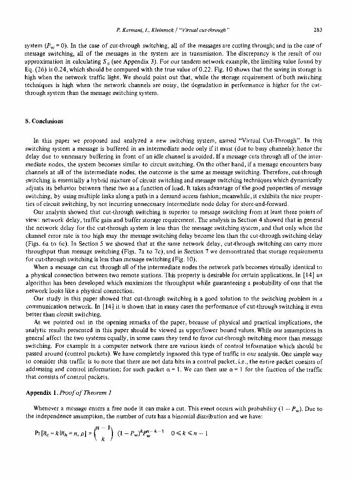
which is independent o f the utilization factor p. Fig. 10 shows the behavior of ~ as a function of Nch for different values of/9. Note that the true limiting value should be
2 + ( n h - 1 ) a
2fin
which can be found by considering the fact that in the limit (Nch -~ oo) there are no waiting messages in the
L0
0.8
0.6
0.4
o;
%-,4
" - - . 2
%- .O5 ,-,o
t0 20 30 40 50 . NUMBER OF CHANNELS PER L INK (Nch)
~h:5 a = . 0 5
Fig. 10. Comparison of Storage Requirement in the Cut-Through System and the Message Switching System.
P. Kermani, L. Kleinrock / "Virtual cut-through" 283
system (Pw -- 0). In the case of cut-through switching, all of the messages are cutting through; and in the case of message switching, all of the messages in the system are in transmission. The discrepancy is the result of our approximation in calculating S-c (see Appendix 3). For our tandem network example, the limiting value found by Eq. (26) is 0.24, which should be compared with the true value of 0.22. Fig. 10 shows that the saving in storage is high when the network traffic light. We should point out that, while the storage requirement of both switching techniques is high when the network channels are noisy, the degradation in performance is higher for the cut- through system than the message switching system.
8. Conclusions
In this paper we proposed and analyzed a new switching system, named "Virtual Cut-Through". In this switching system a message is buffered in an intermediate node only if it must (due to busy channels); hence the delay due to unnessary buffering in front of an idle channel is avoided. If a message cuts through all of the inter- mediate nodes, the system becomes similar to circuit switching. On the other hand, if a message encounters busy channels at all of the intermediate nodes, the outcome is the same as message switching. Therefore, cut-through switching is essentially a hybrid mixture of circuit switching and message switching techniques which dynamically adjusts its behavior between these two as a function of load. It takes advantage of the good properties of message switching, by using multiple links along a path in a demand access fashion; meanwhile, it exhibits the nice proper- ties of circuit switching, by not incurring unnecessary intermediate node delay for store-and-forward.
Our analysis showed that cut-through switching is superior to message switching from at least three points of view: network delay, traffic gain and buffer storage requirement. The analysis in Section 4 showed that in general the network delay for the cut-through system is less than the message switching system, and that only when the channel error rate is too high may the message switching delay become less than the cut-through switching delay (Figs. 6a to 6c). In Section 5 we showed that at the same network delay, cut-through switching can carry more throughput than message switching (Figs. 7a to 7c), and in Section 7 we demonstrated that storage requirements for cut-through switching is less than message switching (Fig. 10).
When a message can cut through all of the intermediate nodes the network path becomes virtually identical to a physical connection between two remote stations. This property is desirable for certain applications. In [ 14] an algorithm has been developed which maximizes the throughput while guaranteeing a probability of one that the network looks like a physical connection.
Our study in this paper showed that cut-through switching is a good solution to the switching problem in a communication network. In [14] it is shown that in many cases the performance of cut-through switching is even better than circuit switching.
As we pointed out in the opening remarks of the paper, because of physical and practical implications, the analytic results presented in this paper should be viewed as upper/lower bound values. While our assumptions in general affect the two systems equally, in some cases they tend to favor cut-through switching more than message switching. For example in a computer network there are various kinds of control information which should be passed around (control packets). We have completely ingnored this type of traffic in our analysis. One simple way to consider this traffic is to note that there are not data bits in a control packet, i.e., the entire packet consists of addressing and control information; for such packet a = 1. We can then use a = 1 for the fraction of the traffic that consists of control packets.
Appendix 1. Proof of Theorem 1
Whenever a message enters a free node it can make a cut. This event occurs with probability (1 - Pw). Due to the independence assumption, the number of cuts has a binomial distribution and we have:
C - 1 ) ( 1 - P w ) k P n w - k - 1 0 < ~ k < ~ n - 1 Pr[nc = k I~ h = n, p] = k

284 P. Kerrnani, L. Kleinrock / "Virtual cut-through"
The conditional generating function [ 12] of the number of cut-throughs may be written as
n - - 1
Cn'°(z) : E[znc[-nh = n 'P] = k=oZ~ z k ( n -k 1) ( l -Pw)ICPnw-k-1
So,
Cn, o(z) = Jew + z(1 - ew)l n - 1
We may now find the conditional mean number of cut-throughs:
dCn, p(z) ~ c ( n ' p ) = E [ n c l h h = n ' P ] = dz I = ( n - 1 ) ( 1 - P w )
z = l
The mean number of cut-throughs is therefore
ffc = ~ E[nclnh = n, p] Pr[hh : n] = (fin -- 1)(1 -- ew) n
The unconditional generating function of the number of cut-throughs is simply
Co(z ) = ~ Cn, o(z) Pr [~h = n] = ~ [Pw + z(1 - Pw)]" - ~ Pr [~h = n] n n
o r
N[P w + z(1 - ew)]) C o ( z ) -
Pw + z(1 - Pw)
where N[z] = E[z h'h] is the generating function of the number of hops.
Appendix 2. Proof o f Theorem 2
For each node at which a cut-through is made, a nodal service time is saved. However, this service time is con- ditioned on the event that the waiting time is zero. So we have
T m - Tc=ffcE[~IW=O]
where ~" is the total delay in a node and ~ is the waiting time in a node. Considering the fact that E ~ Iw = 0] = tm, and that a message can be sent out only after its header is received, the previous equation is changed to
T m - - Tc : nc(tm - th)
where (tm - th) is the saving in delay at each node when the cut-through method is used. Using the value of ffc from Eq. (1), we get
Tc : T m - (nn - 1 )(1 - Pw)(1 - a) tm
Appendix 3. Proof o f Theorem 5
Let S-(m p) be the average value of the total amount of storage required on a path in message switching. At any instant a message in transmission occupies two buffers. All other messages occupy only one buffer, and so we have
S-(P) = [TV(m p) + nh(NchP)] lm (A3.1)
where
~V(mP) = E [number of messages on a path for message switching] = Tm~

P. Kermani, L. Kleinrock / "Virtual cut-through" 285
and (Nchp) is the average number of messages which are being transmitted at each node. The expected number of buffers required at each node is therefore S-m = S ( m P ) / n h • Using Eq. (A3.1) we get
Srn = (Nrn + NchP) lm (A3.2)
where -Nm is the average number of messages at each node. This proves the first part of Theorem 5. To prove Eq. (24) we must describe the operations of the cut-through system in more detail. Let
6 = ceiling {l /a}
= ceiling {(msg length)/(header length)}
(ceiling(x} = smallest integer larger than or equal to x). Consider a message which is being transmitted along a path. Every time that the message cuts through a node, it is allocated a header buffer, i.e., the total amount of storage allocated to it is increased by one header buffer. This process continues until the number of the consecu- tive cuts exceeds ~, after which, for each new header buffer that the message is allocated, it releases one. Fig. 1 la shows this phenomenon for the case 6 = 4. The solid lines show the amount of storage allocated to the message while it is being transmitted along the path, Fig. 1 lb. At time tl the message starts transmission from node 1, the source node. Because we have assumed propagation delay is negligible, at the same time a header buffer is allo- cated to the message at node 2. After th seconds the header is received completely at node 2 (because it can make a cut through this node) and it starts transmission towards node 3 (while using the header buffer at node 2). At node 3 another header buffer is allocated to it instantaneously. This process continues and the amount of the allocated storage increases up to node 5; however, from node 6 on (at time t3), the tail of the message starts leav- ing nodes 2, 3 . . . . ; for each new header buffer it occupies, it releases one, hence the total amount of storage allocated remains unchanged. At time t4 the message arrives in node 8 and a header buffer is allocated to it (so, there is no change in the total amount of buffer allocated to this message on the path). But, after th seconds (at
6 = 4/1 = 4
MESSAGE BEING TRANSMITTED
MESSAGE BEING STORAGE OCCUPANCY RECEIVED
s (t)
(a)
SOURCE
(b)
DESTINATION
t 1 t 2 t 3 ~ t 5 t6
I
h ! , :
1
I
. . . . . i ! L
TIME
Fig. 11. Storage Occupancy m the Cut-Through System.

286 P. Kermani, L. Kleinrock / "Virtual cut-through"
time ts) when the header is received, it is recognized that the selected outgoing link is busy. So the message is blocked and (the remainder of) a message buffer is allocated to it. As the tail of the message leaves the inter- mediate nodes, header buffers are released. When the message is received in full at node 8 (at time t6), the copy of the message present at node 1 (the source node) is dropped and its buffer is released. The right part of Fig. 1 la shows the situation where the number o f consecutive cuts is less than 6.
Let s(t) be the amount of storage allocated to a message at time t. If we approximate the step function s(t), drawn in solid lines in Fig. 1 la , by the broken lines shown in the same figure, we observe a very useful property. The shaded areas in this figure are equal. The interesting fact is that when the number of consecutive cuts is larger than 6, there is no approximation involved (left part o f Fig. 1 la) . By using this property and the assumptions
stated above, it can be shown that
~(o) = ( n ~ m + NehO[nh -- 2(nh -- 1)(1 -- a)(1 - Pw)] )/m (A3.3)
where S-(P) is the expected number of buffers required on a path for cut-through switching. The expected number o f required buffers at a node is, therefore, S-e = S~'P)/nh, or
Sc = Nm +NehP 1 - 2 ~ ( 1 - a ) ( 1 - P w /m (A3.4) nh
(For a detailed derivation of Eqs. (A3.3) and (A3.4) the interested reader is referred to [14] .)
References
[1] Jackson, P.E. and C.D. Stubbs. "A Study of Multi-access Computer Communications," AFIPS Lonference Proceedings, SJCC, 1969, Vol. 34, pp. 491-504.
[ 2] Fuchs, E. and P.E. Jackson. "Estimates of Distributions of Random Variables for Certain Computer Communication Traffic Models," Communications oftheACM, Vol. 13 No. 12, December 1970, pp. 752-757.
[3] Kleinrock, L. Queueing System, Vol. H: Computer Applications, Wiley-Interscience, New York, 1976. [4] Kleinrock, L. and W.E. Naylor. "On Measured Behavior of the ARPA Network," AFIPS Conference Proceedings, NCC,
Chicago, May 1974, Vol. 43, pp. 767-780. [5 ] Kleinrock, L. Communication Nets: Stochastic Message Flow And Delay, McGraw-Hill, New York, 1964 (also Dover, 1972). [6] Kamoun, F. "Design Considerations for Large Computer Communication Networks," Computer Science Department,
School of Engineering and Applied Science, University of California, Los Angeles, UCLA-ENG-7642, April 1976. [7] Frank, H., I.T. Frisch and W. Chou. "Topological Considerations in the Design of the ARPA Network," AFIPS Conference
Proceedings, SJCC, Atlanta City, New Jersey, 1970, pp. 581=587. [8] Cole, G.C. "Computer Network Measurements: Techniques and Experiments," School of Engineering and Applied Science,
University of California, Los Angeles, UCLA-ENG- 7165, 1971. [9] Fultz, G.L. "Adaptive Routing Techniques for Message Switching Computer-Communication Networks," School of Engi-
neering and Applied Science, University of California, Los Angles, UCLA-ENG-7252, July 1972. [10] Little, J. "A Proof Of The Queueing Formula L = kW," Operations Research, Vol. 9, No. 2, March 1961, pp. 383-387. [ 11 ] Jackson J.R. "Networks Of Waiting Lines," Operations Research, Vol. 5, 1957, pp. 518 521. [12] Kleinrock, L. Queueing Systems, Vol. 1: Theory, Wiley-Interscience, New York, 1975. [13] Danthine, A.A.S. and L. Echenauer. "Influence on The Node Behavior of The Node-to-Node Protocol," Inter-Network
Working Group (INWG) Protocol Note No. 22, March 1975, pp. 87-92. [ 14] Kermani, P. "Switching and Flow Control Techniques In Computer Communication Networks," Ph.D. Dissertation, Com-
puter Science Department, School of Engineering and Applied Science, University of California, Los Angeles, UCLA-ENG- 7802. (Also published as Ph.D. Dissertation, December 1977).
[15] Lain, S.S. "Store-and-forward Buffer Requirements in a Packet Switching Network," IEEE Transactions on Communi- cations, Vol. Com-24, No. 4, April 1975, pp. 394-403.