Virtual crack the code – teacher workbook€¦ · Web view2020-03-26 · Watch Connecting the...
42
| NSW Department of Education Stage 4 Technology Mandatory– Digital Technology Virtual crack the code – teacher workbook 01001001 00100000 01100010 01100101 01110100 00100000 01111001 01101111 01110101 00100000 01110100 01101000 01101111 01110101 01100111 01101000 01110100 00100000 01110100 01101000 01101001 01110011 00100000 01110111 01100001 01110011 00100000 01101010 01110101 01110011 01110100 00100000 01100001 00100000 01110010 01100001 01101110 01100100 01101111 01101101 00100000 01100001 01110010 01110010 01100001 01101110 01100111 01100101 01101101 01100101 01101110 01110100 00100000 01101111 01100110 00100000 01101111 01101110 01100101 01110011 00100000 01100001 01101110 01100100 00100000 01111010 01100101 01110010 01101111 01100101 01110011 00101110 education.nsw.gov.au
Transcript of Virtual crack the code – teacher workbook€¦ · Web view2020-03-26 · Watch Connecting the...

| NSW Department of Education
Stage 4 Technology Mandatory– Digital Technology
Virtual crack the code – teacher workbook01001001 00100000 01100010 01100101 01110100 00100000 01111001 01101111 01110101 00100000 01110100 01101000 01101111 01110101 01100111 01101000 01110100 00100000 01110100 01101000 01101001 01110011 00100000 01110111 01100001 01110011 00100000 01101010 01110101 01110011 01110100 00100000 01100001 00100000 01110010 01100001 01101110 01100100 01101111 01101101 00100000 01100001 01110010 01110010 01100001 01101110 01100111 01100101 01101101 01100101 01101110 01110100 00100000 01101111 01100110 00100000 01101111 01101110 01100101 01110011 00100000 01100001 01101110 01100100 00100000 01111010 01100101 01110010 01101111 01100101 01110011 00101110
education.nsw.gov.au

Virtual crack the codeUsing Tinkercad and the Arduino IDE, you are required to complete a series activities to develop basic programming skills. Each activity is designed to extend upon the previous activity and enhance your skills with a range of inputs and outputs that can be used with the Arduino UNO R3.
OutcomesA student:
TE4-1DP designs, communicates and evaluates innovative ideas and creative solutions to authentic problems or opportunities
TE4-2DP plans and manages the production of designed solutions
TE4-4DP designs algorithms for digital solutions and implements them in a general-purpose programming language
TE4-10TS explains how people in technology related professions contribute to society now and into the future
Technology Mandatory Years 7-8 © NSW Education Standards Authority (NESA) for and on behalf of the Crown in right of the State of New South Wales, 2017
1 Stage 4 Technology Mandatory – Digital Technology – teacher workbook

Introduction to ArduinoWatch ‘Introduction to the Arduino UNO and the MAAS ThinkerShield’ – duration 3:24, and label the components of the Arduino UNO below.
Arduino UNO R3 boardThe image below is from tinkercad.com.
Word bank: analogue pins, built-in LED, DC power jack, digital pins, microprocessor, power LED, power pins, reset button, USB port.
© NSW Department of Education, May-2320

Arduino integrated development environmentWatch Connecting the Arduino – duration 3:37, and label the components of the Arduino IDE.
Word bank: debug area, loop, serial monitor, setup, update, verify.
3 Stage 4 Technology Mandatory – Digital Technology – teacher workbook

Using TinkercadTo log into tinkercad, go to the student portal and sign in. Once you are signed in to the portal open G-suite and this will sign you in to Google. Open a new tab and navigate to tinkercad.com, select sign in, and then sign in with Google and this should automatically log you in.
Once you have successfully logged in, from the left side menu select ‘circuits’ and then ‘create new circuit.’
© NSW Department of Education, May-2320

5 Stage 4 Technology Mandatory – Digital Technology – teacher workbook

Creating your first circuitIn the component menu on the right side of the window, search for ‘blink’ and then drag and drop the circuit into the workspace. To navigate around the workspace use left-click and drag on the background to pan, and scroll in and out to zoom in and out.
The blink circuit uses three components: a light emitting diode (LED), a resistor and the Arduino UNO. You will learn more about these components later.
© NSW Department of Education, May-2320

7 Stage 4 Technology Mandatory – Digital Technology – teacher workbook

Testing your first code.The blink circuit has prewritten code for you to use and modify. Tinkercad uses both block and text-based code. For this unit of work we will work with the text-based code. To access the text-based code select the ‘code’ tile, and then the ‘blocks’ drop down menu and change to ‘text.’
Note: When you have the simulation running (if the start simulation button is green) you cannot access this drop down menu until you have stopped the simulation.
A dialogue box will appear asking if you are sure that you want to close the blocks editor, select ‘continue’ and your text-based code will appear. Finally click ‘start simulation’ and observe what happens.
© NSW Department of Education, May-2320

9 Stage 4 Technology Mandatory – Digital Technology – teacher workbook
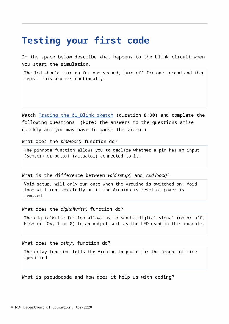
Testing your first codeIn the space below describe what happens to the blink circuit when you start the simulation.
The led should turn on for one second, turn off for one second and then repeat this process con-tinually.
Watch Tracing the 01_Blink sketch (duration 8:30) and complete the following questions. (Note: the answers to the questions arise quickly and you may have to pause the video.)
What does the pinMode() function do?
The pinMode function allows you to declare whether a pin has an input (sensor) or output (actu-ator) connected to it.
What is the difference between void setup() and void loop()?Void setup, will only run once when the Arduino is switched on. Void loop will run repeatedly until the Arduino is reset or power is removed.
What does the digitalWrite() function do?
The digitalWrite fuction allows us to send a digital signal (on or off, HIGH or LOW, 1 or 0) to an output such as the LED used in this example.
What does the delay() function do?
The delay function tells the Arduino to pause for the amount of time specified.
What is pseudocode and how does it help us with coding?
© NSW Department of Education, May-2320

Pseudo code is a computer algorithm written in plain English. Pseudocode helps us with coding as we can design the logic of the code without using the actual coding language. If we have logic errors with the code once it is created we can refer back to the pseudocode to try and solve the issues.
Editing the blink codeReturn to your Tinkercad blink circuit and look at the text code.
Edit the code so that the LED turns on for 2 seconds and off for 2 seconds. When you are ready to test it click ‘start simulation.’
Which lines of code did you edit, and what did you change?
Edit line 9 and 11 and change the value (argument) between the brackets.
If the LED was connected to pin 8 instead of pin 13, which lines of code would you need to edit and what would you change?
Change line 3 to initialise pin 8 as an output. Additionally, change lines 8 and 10 to turn pin 8 on and then off.
11 Stage 4 Technology Mandatory – Digital Technology – teacher workbook

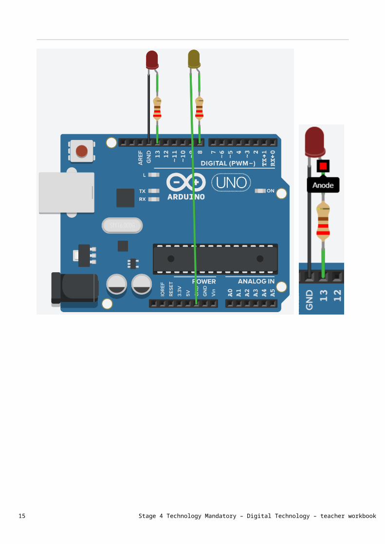
Connecting additional componentsFrom the component menu in Tinkercad search for another LED and drag it into the workspace. When you drag it into the workspace a dialogue box will appear where you can change the name and the colour of the LED if you wish
Additionally drag another resistor into the workspace, and when the dialogue box appears for the resistor change its value to 220Ω (note the default unit will be kΩ)
This symbol (Ω) is the Greek letter Omega and is the symbol for Ohms which is the unit used to compare values of resistors. When attaching an LED to the Arduino, a 220Ω resistor is used to protect the LED from being damaged.
If you have the correct resistor it should have two red bands and one brown band arranged in the same way as the image above.
© NSW Department of Education, May-2320

Connecting an additional LEDConnect the LED and resistor as shown below by click and dragging wires from each of their legs.
LEDs are polarized electrical components. This means that generally electric current can only pass through them in one direction. If an LED is connected incorrectly, even if your code is correct, it will not function as intended. If you place your mouse cursor over a leg of the led in Tinkercad it will show a label of ‘anode’ or ‘cathode’. The anode of the LED should be connected to the pin you have referenced in your code, and the cathode should be connected to ‘GND’ which stands for ground. When adding the second LED connect the anode to pin 8, and the cathode to the pin labelled GND on the other side of the board as shown below.
13 Stage 4 Technology Mandatory – Digital Technology – teacher workbook

© NSW Department of Education, May-2320
Pseudocode and coding challengesWritten is the pseudocode for making the LED connected to pin 13 blink once per second.
Step Blink pseudocode
1 Initialise pin 13 as an OUTPUT
2 Turn LED on pin 13 on
3 Wait 1 second
4 Turn LED on pin 13 off
5 Wait 1 second
6 Repeat
Below is a partially complete pseudocode for making the LEDs connected to pin 13 and pin 8 blink on together and then off together once per second. Complete the incomplete pseudocode, then edit the blink code in Tinkercad according to your pseudocode to make two LEDs blink together. Test it by clicking ‘start simulation.’
Step Blink two LEDs pseudocode
1 Initialise pin 13 as an OUTPUT
2 Initialise pin 8 as an OUTPUT
3 Turn LED on pin 13 on
4 Turn LED on pin 8 on
5 Wait 1 second
6 Turn LED on pin 13 off
7 Turn LED on pin 8 off
8 Wait 1 second
9 Repeat
If you have issues with your code or you get any errors refer to this video – Troubleshooting the code – duration 5:24.
15 Stage 4 Technology Mandatory – Digital Technology – teacher workbook

Traffic light challengeTry connecting an additional LED and code the three LEDs to function like a traffic light. Green, followed by yellow, followed by red and back to green. Note: there should always be one LED on. Use the pseudocode below to help edit the blink code.
Step Traffic light pseudocode
1 Initialise green LED as OUTPUT
2 Initialise yellow LED as OUTPUT
3 Initialise red LED as OUTPUT
4 Turn green LED on
5 Turn yellow LED off
6 Turn red LED off
7 Wait 5000
8 Turn green LED off
9 Turn yellow LED on
10 Turn red LED off
11 Wait 1000
12 Turn green LED off
13 Turn yellow LED off
14 Turn red LED on
15 Wait 5000
16 Repeat
© NSW Department of Education, May-2320

Flow chartsComputer algorithms can also be represented using flow charts. Each unique shape in a flow chart represents a different function. The flowchart below is for the blink sketch. As you can see the flowchart highlights the fact that the setup only runs once, and once the Arduino runs through the loop it returns to the beginning of the loop.
In the space below draw a flow chart for the traffic light challenge. Refer to the pseudocode on the previous page to help you.
17 Stage 4 Technology Mandatory – Digital Technology – teacher workbook

Digital inputsIn the right side component menu search ‘button’ and drag and drop the Arduino starter circuit called ‘button’ into the workspace.
© NSW Department of Education, May-2320

Run the simulation and click the button where shown above. What happens when you click the button? (Hint: observe the built-in LED, labelled ‘L’ on the board.)
The LED will come on when the button is pressed and turn off when the button is released.
19 Stage 4 Technology Mandatory – Digital Technology – teacher workbook

The if statementWatch The if Statement (duration 9:18) and answer the questions below.
Teacher note: suggested solution provided.
Why is creating variables using int helpful?
Helps us by creating an intuitive name for inputs and outputs connected to the Arduino. Also lets us change the value of inputs or outputs in one place rather than throughout the whole code. Int also enables us create variables for the state of the button for example.
What does the digitalRead() function do?
The digitalRead function checks a pin and returns a value of 1 or 0. In the case of the button, if it is pressed the digitalRead function returns a 1 and if it is not pressed it returns a 0.
What happens to the variable called buttonState after the Arduino reads the buttonPin (pin 7)?
The Arduino will change the buttonState variable to a 0 if the button is not pressed and to a 1 if the button is pressed.
How does the if() structure enhance the functionality of the Arduino?
The if structure allows the Arduino to make decisions based on data it is getting from inputs.
How is the double equals sign different to the single equals sign?
The double equals sign is used when we are comparing. The single equals sign is used to as-sign a value to something.
© NSW Department of Education, May-2320

Button challengesReturn to Tinkercad and open the text code for the button circuit.
Edit the code as shown below and then run the simulation.
21 Stage 4 Technology Mandatory – Digital Technology – teacher workbook

Button challengesRun the simulation, and click the button. What has changed and why?
Teacher note: suggested solution provided.
The action of the button should be reversed. When the button is pressed the LED will turn off and when the button is released it will turn on.
Return to the code and change the condition of the ‘if’ statement back to the double equals sign by typing it, or pressing ctrl + z (undo) twice. (Line 36 in the code.)
Change the ‘condition’ of the ‘if’ statement from HIGH to LOW as shown below.
Run the simulation, and click the button. What do you observe happening and why?
The button action should still be reversed.
In both cases above the action of the button should be reversed. When the button is not pressed, the LED turns on, and when it is pressed the LED turns off. There is one additional way to achieve this. Try to work it out by reading through each line of code and considering what it does. If you cannot work it out there is a hint on the next page.
© NSW Department of Education, May-2320

Button ChallengesChange the condition of the ‘if’ statement back to HIGH as shown below. To reverse the action of the button the third way, you need to edit lines 38 and 41.
Write how you changed lines 38 and 41 to reverse the action of the button.
Replace the HIGH in line 38 with LOW and the LOW in line 41 with HIGH.
Note: while working on and editing the code if you make mistakes, and it becomes irreparable, simply delete all of the components, search for the ‘button’ circuit again and drag a new one into the workspace. This will reset the code.
23 Stage 4 Technology Mandatory – Digital Technology – teacher workbook

Button challengesBelow is the flowchart for the button sketch. When the button is pressed we want the LED to stay on for three seconds. Mark on the flow chart below where you could insert a delay.
Once you have identified where to insert the delay, try editing the code in Tinkercad to make the LED stay on for three seconds after the button has been pressed.
Hint: when the code reads the delay function, nothing will change for the length of the delay.
© NSW Department of Education, May-2320

Introduction to binaryThe button used in the last activity is an example of a digital sensor. When the button is read it can only generate 2 possible values a 1 or HIGH if the button is pressed, or a 0 or LOW. This is the essence of binary.
Watch An Introduction to Binary – duration 6:34, and answer the following questions.
Teacher note: suggested solution provided.
What is one digit of binary called?
A bit. (binary digit)
What is a group of eight binary digits called?
A byte.
Why do we use binary?
Fundamentally digital systems can only exchange data as 1 or 0, which is on/HIGH or off/LOW.
How many values can be represented with one byte?
256 values can be represented, though the range is from 0-255.
What does ASCII stand for?
American Standard Code for Information Interchange.
What number represents capital A in ASCII?
65
What number represents lower case A in ASCII?
97
What system do modern computers use to communicate?
Unicode
25 Stage 4 Technology Mandatory – Digital Technology – teacher workbook
© NSW Department of Education, May-2320
Send a message in binaryGo to binarytranslator.com and copy the binary code from the front of the workbook into the translator.
Write the decoded message in the space below.
I bet you thought this was just a random arrangement of ones and zeroes.
Write a short message below to be sent to a friend or relative in plain English.
Use the binary translator to convert it to binary and copy the binary code into the space below.
27 Stage 4 Technology Mandatory – Digital Technology – teacher workbook

Analogue inputsWatch Analogue inputs – duration 9:19 and complete the questions below.
Teacher note: suggested solution provided.
Why is the pin number for the potentiometer referred to with an ‘A’ as in ‘A5’?
Because it is an analogue pin.
What is the difference between digital and analogue signals?
Digital signals are on or off. Analogue signals have a range.
What is the difference between digitalRead() and analogRead()?digitalRead can only return a value of 1 or 0. analogRead returns a value from 0-1023.
What is the range of values the Arduino can read from an analogue sensor?
0-1023.
What is the difference between Serial.print() and Serial.println()?Serial.print will print values to the serial monitor on a continuous, single line. Serial.println will print a value to the serial monitor and then return to the next line.
What does LDR stand for and what does it sense?
Light Dependant Resistor. It can be used to sense the amount of ambient light in a room.
© NSW Department of Education, May-2320

Analogue inputsSearch the component menu for ‘analog input’ and drag the circuit into the workspace.
Start the simulation and use your mouse cursor to change the value of the potentiometer by clicking and dragging it.
What happens to the built-in LED as you change the value of the potentiometer? Why?
The rate of flashing speeds up or slows down. This is due to using a variable which is equivalent to the value of the potentiomater as the argument for the delay function, instead of a fixed value.
29 Stage 4 Technology Mandatory – Digital Technology – teacher workbook

Analogue inputTo see the live value of the sensor you need to add the serial commands mentioned in the ‘Analogue inputs’ video. In the setup at the Serial.begin(9600) function as shown below.
Additionally you need to tell the Arduino what you want to print to the serial monitor, by adding the Serial.print() and Serial.println() functions in the loop.
Run the simulation and open the serial monitor which is at the bottom of the code window. Use your cursor to change the value of the potentiometer and watch the value of the potentiometer in real time.
© NSW Department of Education, May-2320

31 Stage 4 Technology Mandatory – Digital Technology – teacher workbook

Extension activity – analogue input challengeBelow is the pseudocode for making a light that comes on when the potentiometer reaches a value below 500. In the code you have produced you have everything you need to program the Arduino to do this, except for an ‘if’ statement. Look at the pseudocode below and identify where in your code you would need to insert an ‘if’ statement. If you get stuck refer to The if Statement – duration 9:18. (Hint: you may have to delete some lines of code too.)
Step Traffic light pseudocode
1 Initialise built-in LED on pin 13 as an OUTPUT
2 Initialise the sensor connected to A0 as an OUTPUT
3 Start the serial monitor
4 Read the value of the sensor
5 If the sensor is <=500
6 Turn the LED on pin 13 on
7 Else
8 Turn the LED on pin 13 off
9 Print “The sensor value is:” to the serial monitor
10 Print the value of the sensor and return to a new line
© NSW Department of Education, May-2320

Marking Criteria
Criteria Grade
Student demonstrates extensive knowledge of Arduino programming data types, functions and structures.Student demonstrates extensive knowledge of programming logic.Student designs comprehensive, logical algorithms using pseudocode and flow charts.Student demonstrates extensive knowledge of binary and its application in digital systems.
A
Student demonstrates thorough knowledge of Arduino programming data types, functions and structures.Student demonstrates thorough knowledge of programming logic.Student designs logical algorithms using pseudocode and flow charts.Student demonstrates thorough knowledge of binary and its application in digital systems.
B
Student demonstrates sound knowledge of Arduino programming data types, functions and structures.Student demonstrates sound knowledge of programming logic.Student designs algorithms using pseudocode and flow charts.Student demonstrates sound knowledge of binary and its application in digital systems.
C
Student demonstrates basic knowledge of Arduino programming data types, functions and structures.Student demonstrates basic knowledge of programming logic.Student designs algorithms using pseudocode and flow charts.Student demonstrates basic knowledge of binary and its application in digital systems.
D
Student demonstrates elementary knowledge of Arduino programming data types, functions and structures.Student demonstrates elementary knowledge of programming logic.Student attempts to design algorithms using pseudocode and flow charts.Student demonstrates elementary knowledge of binary and its application in di-gital systems.
E
33 Stage 4 Technology Mandatory – Digital Technology – teacher workbook