Virginia State University Design Guidelines 2013 1-15-14vsu.edu/files/docs/capital-outlay/Virginia...
68
Virginia State University Design Guidelines JANUARY 15, 2014
Transcript of Virginia State University Design Guidelines 2013 1-15-14vsu.edu/files/docs/capital-outlay/Virginia...
Virginia State University
Design Guidelines
JANUARY 15, 2014

Virginia State University
Design Guidelines
2 | P a g e
DESIGN PHILOSOPHY & PLANNING STANDARDS
The University’s Design Guidelines are intended for the use of Architects, Landscape Architects, and
Engineers involved in the preparation of Construction Documents for the University. The Design
Guidelines are to be used as a reference for Facilities Project Managers and other personnel whose
responsibilities include executing institutional lessons-learned through design, construction and in-
house services.
The Design Guidelines provide routine and technical requirements that are generally applicable to all
design and construction. As part of the contractual agreement, between the design professional and
the University, the conscientious application of the Design Guidelines is a tool to expedite the design
and construction process in a mutual, partnering endeavor. In a similar approach, Facilities
Management personnel are accountable for executing the purpose of the Guidelines.
The arrangement of this First Edition of the University’s Design Guidelines is intended to be user
friendly, with stress on a pre-design understanding for a partnering effort between the Architect, the
Engineer, the End User, and a variety of Facilities personnel under the responsibility of the Project
Manager. The Code Review Team is responsible for ensuring these Guidelines are implemented.
Periodic supplements to these Design Guidelines may be available and circulated to anyone on record
as having a copy of the Design Guidelines. These Design Guidelines and any added supplements shall be
followed for all projects unless due process is used for waivers or modifications.
The University’s Design Guidelines shall apply to all design projects unless specifically waived by the
Director of Capital Outlay. The Design Guidelines are to be incorporated into the Design and
Construction Documents and not referenced. All waiver requests are to be submitted by the Project
Manager to the Director Capital Outlay.

Virginia State University
Design Guidelines
3 | P a g e
APPLICABLE CODES, GUIDELINES, MANUALS, and POLICIES
ADA Accessibility Guidelines for Buildings and Facilities ADAAG
2010 ADA Standards for Accessible Design ASAD
Construction and Professional Services Manual - 2013 CPSM
Public Right-of-Way Accessibility Guidelines PROWAG
Virginia Energy Conservation Code - 2009 VECC
Virginia Construction Code – 2009 VCC
Virginia Public Procurement Act VPPAB
Virginia Rehabilitation Code – 2009 VREHAB
Virginia Uniform Statewide Building Code – 2009 VUSBC
National Electrical Code – 2008 NEC
Virginia State University Safety Handbook
Virginia State University Annual Standards and Specifications for Erosion and Sediment
Control
Chesterfield County Water and Sewer Specifications and Procedures – 2002
WEB RESOURCES
BCOM Web Page
http://www.dgs.virginia.gov/DEB/BCOM/tabid/375/Default.aspx
DGS Forms Center
http://www.dgs.state.va.us/FormsCenter/tabid/820/Default.aspx

Virginia State University
Design Guidelines
4 | P a g e
TABLE OF CONTENTS
DIVISION 1 - GENERAL REQUIREMENTS ............................................................ 10
VSU Requirements ........................................................................................................................................ 10
Summary ....................................................................................................................................................... 10
END OF SECTION ........................................................................................................................................... 10
DIVISION 2 – SITEWORK .................................................................................... 11
Demolition ..................................................................................................................................................... 11
Erosion and Sediment Control ...................................................................................................................... 11
Site Clearing ................................................................................................................................................... 11
Landscape Standards ..................................................................................................................................... 11
END OF SECTION ........................................................................................................................................... 12
DIVISION 3 - CONCRETE .................................................................................... 13
Concrete Paving............................................................................................................................................. 13
Reinforcement ............................................................................................................................................... 13
Concrete Placement ...................................................................................................................................... 13
Curing ............................................................................................................................................................ 13
Glass Fiber Reinforced Concrete (GFRC) ....................................................................................................... 14
END OF SECTION ........................................................................................................................................... 14
DIVISION 4 - MASONRY ..................................................................................... 15
Exterior Enclosure ......................................................................................................................................... 15
Brick Masonry ................................................................................................................................................ 15
Veneer Masonry ............................................................................................................................................ 16
Brick Pier........................................................................................................................................................ 17
Expansion Joints ............................................................................................................................................ 18
Unit Pavers .................................................................................................................................................... 18
Existing Brick.................................................................................................................................................. 18
Masonry Retaining Walls ............................................................................................................................... 18
Concrete Retaining Walls .............................................................................................................................. 19
Seat Walls ...................................................................................................................................................... 20
Cast Stone Masonry ...................................................................................................................................... 21
END OF SECTION ........................................................................................................................................... 21
DIVISION 5 - METALS ........................................................................................ 22
Decorative Fences & Gates ........................................................................................................................... 22
END OF SECTION ........................................................................................................................................... 22
DIVISION 6 - WOOD, PLASTICS and COMPOSITES .............................................. 23
END OF SECTION ........................................................................................................................................... 23

Virginia State University
Design Guidelines
5 | P a g e
DIVISION 7 - THERMAL AND MOISTURE PROTECTION- THERMAL INSULATION . 24
Roofing .......................................................................................................................................................... 24
Shingles ......................................................................................................................................................... 24
Thermal Insulation ........................................................................................................................................ 25
END OF SECTION ........................................................................................................................................... 25
SUSTAINABLE DEISGN REQUIREMENTS (LEED) FOR NEW CONSTRUCTION &
MAJOR RENOVATIONS ...................................................................................... 26
New Construction .......................................................................................................................................... 26
Major Renovations ........................................................................................................................................ 26
Enhanced Commissioning ............................................................................................................................. 26
Selection of LEED points during schematic design ........................................................................................ 26
END OF SECTION ........................................................................................................................................... 26
DIVISION 8 – DOORS and WINDOWS ................................................................ 27
Interior Doors ................................................................................................................................................ 27
Locksets ......................................................................................................................................................... 27
Kick Plates ...................................................................................................................................................... 27
Exterior Aluminum Windows ........................................................................................................................ 27
END OF SECTION ........................................................................................................................................... 27
DIVISION 9 –FINISHES ....................................................................................... 28
Interior Walls – Gypsum Board ..................................................................................................................... 28
Paint .............................................................................................................................................................. 28
Floor Finishes ................................................................................................................................................. 29
Concrete Floor ............................................................................................................................................... 30
Ceramic Tile ................................................................................................................................................... 30
Resilient Base ................................................................................................................................................ 30
Carpet ............................................................................................................................................................ 30
Ceiling Finish .................................................................................................................................................. 31
END OF SECTION ........................................................................................................................................... 31
DIVISION 10 – SPECIALTIES ............................................................................... 32
Fire Extinguisher Cabinet & Extinguishers ..................................................................................................... 32
Interior Signage ............................................................................................................................................. 32
Toilet Accessories .......................................................................................................................................... 32
Wall & Corner Guards ................................................................................................................................... 32
Fire Caulking .................................................................................................................................................. 32
END OF SECTION ........................................................................................................................................... 32
DIVISION 11 - EQUIPMENT ................................................................................ 33
END OF SECTION ........................................................................................................................................... 33
DIVISION 12 - FURNISHINGS .............................................................................. 34
Virginia State University
Design Guidelines
6 | P a g e
END OF SECTION ........................................................................................................................................... 34
DIVISION 13 - SPECIAL CONSTRUCTION ............................................................. 35
END OF SECTION ........................................................................................................................................... 35
DIVISION 14 - CONVEYING SYSTEMS ................................................................. 36
Elevators ........................................................................................................................................................ 36
Elevator Key Boxes ........................................................................................................................................ 36
END OF SECTION ........................................................................................................................................... 36
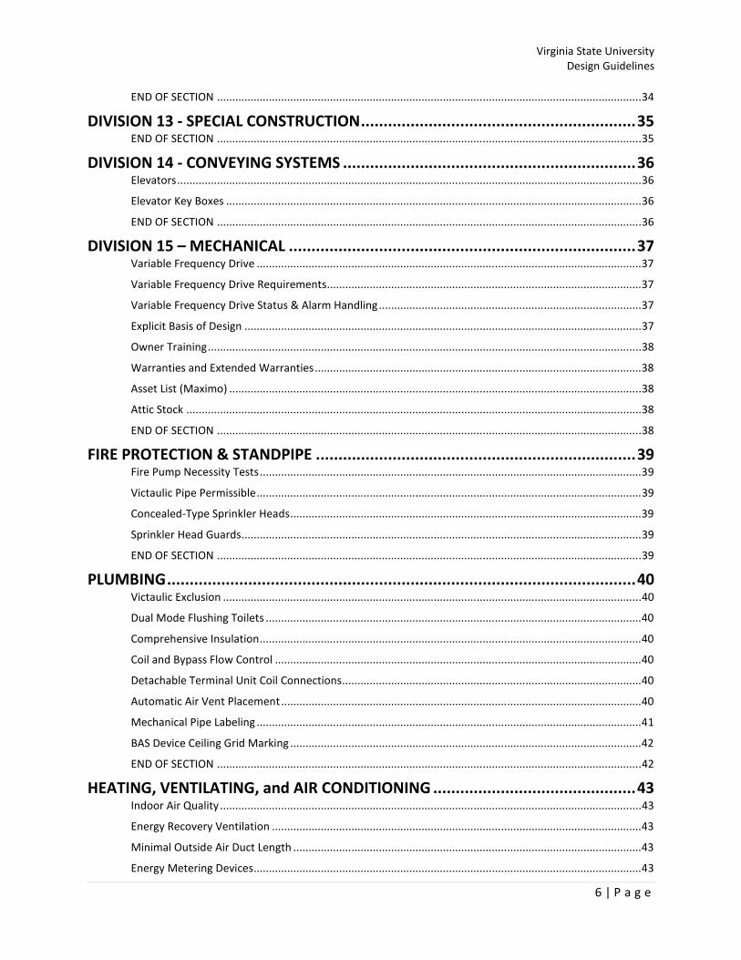
DIVISION 15 – MECHANICAL ............................................................................. 37
Variable Frequency Drive .............................................................................................................................. 37
Variable Frequency Drive Requirements ....................................................................................................... 37
Variable Frequency Drive Status & Alarm Handling ...................................................................................... 37
Explicit Basis of Design .................................................................................................................................. 37
Owner Training .............................................................................................................................................. 38
Warranties and Extended Warranties ........................................................................................................... 38
Asset List (Maximo) ....................................................................................................................................... 38
Attic Stock ..................................................................................................................................................... 38
END OF SECTION ........................................................................................................................................... 38
FIRE PROTECTION & STANDPIPE ....................................................................... 39
Fire Pump Necessity Tests ............................................................................................................................. 39
Victaulic Pipe Permissible .............................................................................................................................. 39
Concealed-Type Sprinkler Heads ................................................................................................................... 39
Sprinkler Head Guards ................................................................................................................................... 39
END OF SECTION ........................................................................................................................................... 39
PLUMBING ........................................................................................................ 40
Victaulic Exclusion ......................................................................................................................................... 40
Dual Mode Flushing Toilets ........................................................................................................................... 40
Comprehensive Insulation ............................................................................................................................. 40
Coil and Bypass Flow Control ........................................................................................................................ 40
Detachable Terminal Unit Coil Connections .................................................................................................. 40
Automatic Air Vent Placement ...................................................................................................................... 40
Mechanical Pipe Labeling .............................................................................................................................. 41
BAS Device Ceiling Grid Marking ................................................................................................................... 42
END OF SECTION ........................................................................................................................................... 42
HEATING, VENTILATING, and AIR CONDITIONING ............................................. 43
Indoor Air Quality .......................................................................................................................................... 43
Energy Recovery Ventilation ......................................................................................................................... 43
Minimal Outside Air Duct Length .................................................................................................................. 43
Energy Metering Devices ............................................................................................................................... 43

Virginia State University
Design Guidelines
7 | P a g e
Duct Air Leakage Testing ............................................................................................................................... 44
Outdoor Air Coil Freeze Protection ............................................................................................................... 44
Heat Trace ..................................................................................................................................................... 44
XY Plane Coil Connections on RTUs ............................................................................................................... 44
Filter Change Data ......................................................................................................................................... 45
Water-Shedding Outdoor Insulation ............................................................................................................. 45
Appropriately Pinned Insulation ................................................................................................................... 45
Sized to Return the Space to Control ............................................................................................................ 45
Designed for Heat Wheel Replacement and Maintenance ........................................................................... 45
Total BAS Integration .................................................................................................................................... 45
END OF SECTION ........................................................................................................................................... 45
DIVISION 16 - ELECTRICAL ................................................................................. 46
Site Lighting – General................................................................................................................................... 46
Luminaires ..................................................................................................................................................... 46
Lamps and Ballast .......................................................................................................................................... 47
Light Poles ..................................................................................................................................................... 47
Light Bollards ................................................................................................................................................. 48
Site Lighting – Foundation ............................................................................................................................. 48
Occupancy Lighting Controls ......................................................................................................................... 48
Day-Lighting Control ...................................................................................................................................... 49
Dedicated BAS Power & UPS ......................................................................................................................... 49
BAS Lighting Control ...................................................................................................................................... 49
Power ............................................................................................................................................................ 49
END OF SECTION ........................................................................................................................................... 49
DIVISION 17 - BUILDING AUTOMATION ............................................................ 50
Integrated Automation.................................................................................................................................. 50
Control Point List Development .................................................................................................................... 50
BAS Front – End Design ................................................................................................................................. 50
Residence Hall Terminal Unit Control ........................................................................................................... 51
Thermostat Covers ........................................................................................................................................ 51
BAS Front – End Terminal Unit Indicator Colors............................................................................................ 51
Chiller Control Strategy ................................................................................................................................. 51
Hot Water Reset Control Strategy ................................................................................................................. 51
Alarm Handling .............................................................................................................................................. 51
Rainwater Irrigation Control.......................................................................................................................... 51
Data Backup .................................................................................................................................................. 51
Educational “Dashboard” Contents............................................................................................................... 52
Educational “Dashboard” Interactivity .......................................................................................................... 52

Virginia State University
Design Guidelines
8 | P a g e
*Owner-Provided Static IP Addresses ........................................................................................................... 52
Humidity Tracking, Sampling Locations and Dehumidification ..................................................................... 52
Mandatory Unoccupied Operation Mode ..................................................................................................... 53
Unoccupied Humidity Control ....................................................................................................................... 53
END OF SECTION ........................................................................................................................................... 53
COMMUNICATIONS .......................................................................................... 54
Access ............................................................................................................................................................ 54
Heating, Ventilation and Air Conditioning (HVAC) ........................................................................................ 54
END OF SECTION ........................................................................................................................................... 55
ELECTRONIC SAFETY and SECURITY ................................................................... 56
Access Control System .................................................................................................................................. 56
Exterior Door Security Card Readers ............................................................................................................. 56
Interior Wing or Pod Door Security Card Readers ......................................................................................... 56
Security Cameras ........................................................................................................................................... 56
Egress Locks ................................................................................................................................................... 56
END OF SECTION ........................................................................................................................................... 56
EXTERIOR IMPROVEMENTS ............................................................................... 57
Exterior Building Colors ................................................................................................................................. 57
Brick Walkways and Ramps ........................................................................................................................... 58
Concrete Bollards .......................................................................................................................................... 61
Landscape Chain and Post ............................................................................................................................. 62
Exterior Signage ............................................................................................................................................. 62
Graphic Standards and Use of Logo .............................................................................................................. 63
Asphalt Paving ............................................................................................................................................... 64
END OF SECTION ........................................................................................................................................... 64
TURF AND GRASSES .......................................................................................... 65
END OF SECTION ........................................................................................................................................... 65
UTILITIES ........................................................................................................... 66
Required Notice for planned Service Disruptions (Steam, water, sewer, power)......................................... 66
DVP service requests ..................................................................................................................................... 66
Requests for Easements ................................................................................................................................ 66
Tracer wire/balls............................................................................................................................................ 66
Updating of master utility plans .................................................................................................................... 66
Steam ............................................................................................................................................................ 66
Gas ................................................................................................................................................................. 66
Water............................................................................................................................................................. 66
Junction Boxes ............................................................................................................................................... 67
END OF SECTION ........................................................................................................................................... 67

Virginia State University
Design Guidelines
9 | P a g e
APPENDICES...................................................................................................... 68

Virginia State University
Design Guidelines
10 | P a g e
DIVISION 1 - GENERAL REQUIREMENTS
VSU Requirements
Sign in at the Police Station
Contractor Handbook
Parking Pass and contractor parking lots
Sign in at Physical Plant
No parking or driving on grass or sidewalks
Protection of grounds and hardscapes
Emergency Contact Information
Adherence to University Policies
• Excavation
• Hot Work
• Environmental Hazards
• Inspections
Academic Calendar and blackout dates
Disruption of traffic
Summary
END OF SECTION

Virginia State University
Design Guidelines
11 | P a g e
DIVISION 2 – SITEWORK
Demolition
Prior to any demolition, the Contractor is to submit a demolition plan to the University for approval.
Erosion and Sediment Control
The University self manages the campus E&S Plan. All E&S control measures must be identified on
plans, submitted for approval and accepted by the University, and conform to all University, state
and federal regulations.
The Engineer shall show all E&S control measures on the contract documents and obtain approval
from DEQ.
The University will file for the Virginia Stormwater Management Program (VSMP) permit prior to the
start of construction and will transfer the permit over to the contractor.
Prior to commencement of work, the University, A/E and Contractor will meet with DCR to review
the Erosion and Sediment Control plans for permit approval.
The contractor will be responsible to prepare a Stormwater Pollution Prevention Plan from the
approved VSMP Permit. A copy of the Stormwater Pollution Prevention Plan (SWPP) shall be kept at
the jobsite at all times.
The Contractor is required to have a Responsible Land Disturber (RLD) onsite at all times.
The University will perform the Erosion Control Measure inspections and will require the contractor
to sign all reports and keep a copy on file at the jobsite. The contractor will be responsible to keep
the Erosion Control Measures functional at all times during construction. All erosion control
measures will be removed once the jobsite has been stabilized.
Site Clearing
The A/E shall provide Contract Documents and Specifications for the following work:
• Clearing and Grubbing
• Removal of Trees and other vegetation
• Protection of existing trees
• Topsoil stripping
Burning on VSU Campus is prohibited
Selective clearing shall be done around trees, shrubs grass, and other vegetation as required to
permit installation of the work.
Landscape Standards
Acceptable Plants
Prohibited Plants
Warranty Period

Virginia State University
Design Guidelines
12 | P a g e
CPTED – Crime Prevention Through Environmental Design
• In design consideration for landscaping around campus and in front of buildings.
Designers must take into consideration the CPTED guidelines.
Irrigation
END OF SECTION

Virginia State University
Design Guidelines
13 | P a g e
DIVISION 3 - CONCRETE
Concrete Paving
All concrete paving work shall conform to the provisions of the Contract Documents, VDOT
Standards and the current VDOT Road and Bridge specifications and shall apply to the following
items:
• Curbs and gutters
• Walkways/sidewalks
• Service area pavement.
For new construction, the width of sidewalks shall be a minimum of 6’ and use Heavy Duty Concrete
(See Detail Below). The sidewalks shall have a minimum concrete compressive strength of 3500 psi
and shall contain reinforcement.
Reinforcement
Welded Wire Mesh shall be included in all concrete sidewalk operations.
Concrete Placement
Placement of concrete shall be in one continuous operation with the installation of the welded wire
mesh prior to concrete pour. Place concrete, strike off, and screed.
The contractor will be required to following the placement guidelines in the Contract Documents
and VDOT Road and Bridge Specifications.
Curing
The contractor is required to protect all freshly placed concrete from premature drying and
excessive cold or hot temperatures. Contractor will be required to follow the guidelines outlined in
the Contract Documents and VDOT Road and Bridge Specifications.
Unformed Surfaces: Begin curing immediately after finishing concrete. Cure unformed surfaces,
including floors and slabs, concrete floor toppings, and other surfaces.

Virginia State University
Design Guidelines
14 | P a g e
Glass Fiber Reinforced Concrete (GFRC)
On new construction projects that include Architectural features such as column covers, fascia units,
cornices, soffits, balusters, railings and accessories, the University would like to use GFRC units.
Acceptable Manufacturers include:
• Stromberg Architectural
• Clark Pacific
• Concrete Designs, Inc.,
• Whitestone Designs, Inc.
Sidewalk Design – Scoring.
END OF SECTION

Virginia State University
Design Guidelines
15 | P a g e
DIVISION 4 - MASONRY
Exterior Enclosure
The University’s goal is to retain the historic character of the existing buildings and match the
general architectural style and character of the campus for new building construction. All exterior
masonry design and construction shall conform to all applicable code requirements, including the
applicable standards adopted by the building codes.
Face Brick and other masonry veneers shall be backed with masonry units.
Cut stone, rough stone, and slate shall be used only for trim, and not as the basic wall material.
The use of metal stud framing in brick veneer exterior walls is not acceptable. Exceptions require
approval premised on detailed information regarding moisture barriers and stainless steel
anchorage.
Brick Masonry
Face Brick selections shall conform to ASTM C216 and shall be Grad SW, Type FBS and a minimum
compressive strength of 3,000psi. A Minimum Net Area Assemblage Compressive Strength shall be
1500 psi.
Historic Face Brick combinations are as follows:
The Main Field Brick shall be Carolina Ceramics Smooth Red Common in Modular Size. The Header
Brick shall be:
Taylor Clay Black Onyx Smooth in Modular Size
Taylor Clay Royal Salisbury Smooth in Modular Size
Carolina Ceramics Burgundy Smooth in Modular Size
The headers are a Flemish Bond style and are 33% of the total wall. Of that 33%, the breakdown is
as follows:
16% of Black Onyx Smooth
16% of Royal Salisbury Smooth
1% or Burgundy Smooth
The Flemish Bond Headers could be adjusted down to 15% for the Black Onyx Smooth and the Royal
Salisbury Smooth; the Burgundy Smooth could then be increased to 3%.

Virginia State University
Design Guidelines
16 | P a g e
Veneer Masonry
Face Brick and other masonry veneers shall be backed with masonry units.
Cut stone, rough stone, and slate shall be used only for trim, and not as the basic wall material.
Non-Academic
The University has designated the following Precast selections for non-academic and non-residence
hall buildings:
All precast shall be Seaboard Concrete Products #7105 - Dover White with Machine Honed Finish
All EIFS Ceiling systems at Balconies shall be Masterwall #108 - Burris White
Residence Hall
The University has designated the following Precast selections for Residence Halls (Residence Hall
Buildings):
All Precast shall be Stafford Stone Works Color 261
All Composite Wall Panels shall be Reynobond Bone White

Virginia State University
Design Guidelines
17 | P a g e
Brick Pier
Entry columns shall match existing piers on campus. .

Virginia State University
Design Guidelines
18 | P a g e
Expansion Joints
All Brick Expansion Joints shall be Dow Corning 790 - Rustic Brick.
All Precast Expansion Joint shall be Dow Corning 790 Precast White.
All Storefront and Curtain Wall Expansion Joints shall match Kawneer Bone White.
All Storefront and Curtain Wall Insulated Spandrel Panels shall be Mapes Bone White.
Unit Pavers
All Unit Pavers shall be Pine Hall Brick Pathway Full Range Traditional Edge Pavers – English Edge FR
4x8.
Existing Brick
Removal of existing brick for use on additions or renovations shall be carefully executed to prevent
cracks, splits, spalls, and damage to the surface integrity of the units.
Masonry Retaining Walls
All CMU Retaining Walls installations shall be constructed and installed per the guidelines shown in
below

Virginia State University
Design Guidelines
19 | P a g e
Concrete Retaining Walls
All Concrete Retaining Walls installations shall be constructed and installed per the guidelines shown
in below.

Virginia State University
Design Guidelines
20 | P a g e
Seat Walls
All seat wall cap installations shall be constructed and installed per the guidelines shown below.
Cast stone seat wall units; include construction details, material descriptions, dimensions of
individual components and profiles, and finishes.
Acceptable Manufacturers: Subject to compliance with requirements, provide products by one of
the following:
• Arban Precast Stone, Ltd.
• Safford Stone Works, Inc.
• ACCI-Tannerstone.
• Cast Stone Systems, Inc.
• Con Art Precast, LLC.
• RockCast.
• Nitterhouse Masonry Products, LLC
Regional Materials: Provide cast stone units that have been manufactured within 500 miles of
Project site from aggregates and cement that have been extracted, harvested, or recovered, as well
as manufactured, within 500 miles of Project site.
Show fabrication and installation details for cast stone units. Include dimensions, details of
reinforcement and anchorages if any, and indication of finished faces.

Virginia State University
Design Guidelines
21 | P a g e
Cast Stone Masonry
The University prefers the use of Cast stone units at the following exterior locations;
• Windowsills.
• Lintels.
• Arches.
• Coping.
• Wall caps.
• Belt courses.
• Water tables.
• Keystone.
Acceptable Manufacturers include:
• Arban Precast Stone, Ltd.
• Safford Stone Works, Inc.
• ACCI-Tannerstone.
• Cast Stone Systems, Inc.
• Con Art Precast, LLC.
• RockCast.
• Nitterhouse Masonry Products, LLC
END OF SECTION

Virginia State University
Design Guidelines
22 | P a g e
DIVISION 5 - METALS
Decorative Fences & Gates
All new projects that separate the University’s property with adjacent property owners will be
separated by the use of fencing. The University prefers the traditional wrought-iron looking
aluminum.
Manufacture:
• Ultra Aluminum Manufacturing, INC.
END OF SECTION

Virginia State University
Design Guidelines
23 | P a g e
DIVISION 6 - WOOD, PLASTICS and COMPOSITES
END OF SECTION

Virginia State University
Design Guidelines
24 | P a g e
DIVISION 7 - THERMAL AND MOISTURE PROTECTION- THERMAL
INSULATION
Roofing
Roofing material shall be designed with keeping with the historic architectural look of slate roofs
throughout campus. New or reroofing projects on VSU’s campus shall require the A/E to design to
this standard. Economy, aesthetics, constructibility, and compatibility shall be considered in
evaluation and design of all roof systems Color of shingles and other steep slope roofs
The A/E will verify if the University has a current roofing survey for the existing buildings.
The A/E is required to provide conceptual drawings and specifications prepared by a licensed
Virginia Architect or Engineer.
Standing Seem Metal roofs is not the normal roof for design consideration.
Acceptable Low Slope Roofing Membranes are;
• EPDM, single-ply, 45 mil minimum thickness, 60 mil preferred
• KEE, Single-ply, 45 mil min. thickness
• NBP, single-ply, 45 mil Min. thickness
• PVC, Single-ply, ASTM D 4434 Type III and Type IV, 45 mil minimum thickness
• TPO, Single-ply, 60 mil minimum thickness
Re-Roofing – is required for over 25% of the roof area in a calendar year:
• Provided secondary (Emergency) roof drains in accordance with the requirements for new
construction.
• Provide guarantees for new construction
• Provide insulation in the roof covering assembly in accordance with the requirements for
new roof construction.
The Owner will have a full-time inspector on site while the roof is being applied. The Owner shall
inspect the roof(s) semi-annually, as a condition of the roofing guarantee. The Owner shall also
inspect the roof(s) before the two-year guarantee expires.
During construction, the contractor will be required to make sure the roof is sealed prior to ending
operations each day.
Placement of roofing materials during construction
Placement of kettles away from outside air intakes
Response to roof leaks during construction
Shingles
All Non-Residence Building Shingles shall be Timberline in Oyster Gray.
All Residence Building Shingles shall be CertainTeed Hatteras Shingles in Windswept Gray.
Dimensional shingles 30-year warranty min.

Virginia State University
Design Guidelines
25 | P a g e
Thermal Insulation
As part of the University’s roof design, the thermal insulation should exceed the minimum
requirements of ASHRAE 90.1-2004, with R-10 at perimeter of slab, R-7.5 continuous insulation, and
R-19 batt insulation in stud cavities on exterior walls, with R-30 insulation in attic.
END OF SECTION
Virginia State University
Design Guidelines
26 | P a g e
SUSTAINABLE DESIGN REQUIREMENTS (LEED) FOR NEW
CONSTRUCTION & MAJOR RENOVATIONS
New Construction
The new construction should be designed to achieve USGBC LEED Certification for Silver Rating, and
the LEED Scorecard Identifying Credits targeted should be submitted to the University Capital Outlay
Department for approval.
Major Renovations
For major renovations, windows should have high-performance, insulated glass units with low-E
coating, providing a SHGC-.29 and a U-value of 0.33.
Exhaust ducts from all Bathrooms should be connected to Energy Recovery Units with a heat wheel,
which captures heat from exhaust to precondition the outside air supplied for make-up air when
practical.
Enhanced Commissioning
Selection of LEED points during schematic design
END OF SECTION
Virginia State University
Design Guidelines
27 | P a g e
DIVISION 8 – DOORS and WINDOWS
Interior Doors
All doors shall have a minimum width of 3’-0” and minimum height of 7’-0” using only
manufacture’s standard door sizes.
All wood doors shall be 5-ply, solid core with a minimum thickness of 1 3/4”. Specifications shall call
for a lifetime warranty of wood doors.
All metal doorframes shall be of welded construction.
Clear glazed vision panels shall be used in all classroom and stair doors.
Due to higher maintenance and replacement costs, bi-fold, folding doors, or folding grilles are
prohibited.
Hollow core wood doors and plastic laminated doors are prohibited.
Pocket doors are prohibited.
Locksets
General: The University uses Best Mortise Locksets with Coremax Cores for J-Style keys. All cores
shall be 7-pin and interchangeable core cylinders. Best shall supply all cylinders and cores
accordingly.
Locksets shall be Best Mortise Locksets, Extra-Heavy Duty, Security Grade 2, and be UL10C.
All interior locksets shall have lever handles with a removable core.
The Facilities Management lock shop shall accomplish all keying and installation of cylinders and
cores, with the exception of construction cores, which shall be the responsibility of the contractor.
Locks shall be reviewed with University Police and the locksmith shop for approval no later than
submission of working drawings. Use of Combination Locks is not permitted.
Kick Plates
Doors subject to abuse by equipment associated with building function shall have kick plates.
Exterior Aluminum Windows
Exterior Aluminum windows on any new construction or renovation project are prohibited.
END OF SECTION

Virginia State University
Design Guidelines
28 | P a g e
DIVISION 9 –FINISHES
The Capital Outlay Department and A/E shall meet with the End User to review the acceptable interior
finishes. The End User will be given the opportunity to pick from a list of acceptable finishes.
Interior Walls – Gypsum Board
The minimum single layer thickness shall be 5/8” for walls. Abuse resistant gypsum board shall be
provided in corridors and other similar high-traffic areas.
All gypsum board shall be mold resistant.
All gypsum board in wet areas such as toilets, baths, janitor closets, and slop sink areas shall be mold
and moisture resistant.
Paint
Paint finishes other than those listed below, require documented University approval through the
Capital Outlay Department, and shall be discussed during the design process.
All paints, glues etc. need to be low VOC – showing standard SW Latex.
To assure economical repainting in the future, all interior walls shall be painted an eggshell finish in
a color to match Benjamin Moore OC - 95. “Navaho White”
• Gypsum board. Drywall (Walls) Latex System
o Prime Coat: Interior latex primer/sealer. Intermediate Coat: Interior latex
matching topcoat.
o Topcoat: Interior latex (eggshell).
All gypsum ceilings shall be painted a flat finish in a color to match Benjamin Moore White OC-59
“Vanilla Milkshake”
• Drywall (Ceilings) Latex System
o Prime Coat: Interior latex primer/sealer.
o Intermediate Coat: Interior latex matching topcoat.
o Topcoat: Interior latex (eggshell)
Metal surfaces (doors, doorframes) will receive semi-gloss paint of the same tone. In the same hue,
moisture-resistant paint with a semi-gloss finish will be specified for public and student bathrooms,
housekeeping rooms, laundry/recycling rooms, and janitors’ closets.
Accent Colors
• Game Room – Pittsburgh Paints #547-7 “Annapolis Blue”, Benjamin Moore #2016-10
“Startling Orange”
• Multi-Purpose, Main Commons, Corridor- Benjamin Moore #1053 ”Sierra Hills”
• Stairwells - Pittsburgh Paints #547-7 “Annapolis Blue”
Virginia State University
Design Guidelines
29 | P a g e
Athletics Colors
• Pantone Blue 286C
• Pantone Orange 165U
At end of each workday, the contractor will be responsible for removing rubbish, empty cans, rags,
and other discarded materials from Project site.
Floor Finishes
Interior flooring, wall covering, and ceilings shall be selected from manufacturer’s standard material
selection. Custom material selections are prohibited, irrespective of initial lower costs resulting
from significant quantities. Future replacement or matching materials are an unnecessary premium
in cost.
One of the preferred VSU flooring:
Floor Plank:
• Mannington Commercial Luxury Vinyl Plank Flooring – Nature’s Paths (3”x36”, 4”x36” or
6”x36”)
VCT – Standard EXCELON® MultiColor™ Resilient Tile Flooring manufactured by Armstrong World
Industries, Inc., in color selected from the range currently available from Armstrong World
Industries, Inc.], having a nominal total thickness of 1/8 in. (3.2 mm), 12 in. x 12 in. (305 mm x 305
mm), composed of polyvinyl chloride resin binder, plasticizers, fillers, and pigments with colors and
texture dispersed uniformly throughout its thickness. Vinyl composition tile shall conform to the
requirements of ASTM F 1066, Class 2 – through pattern.
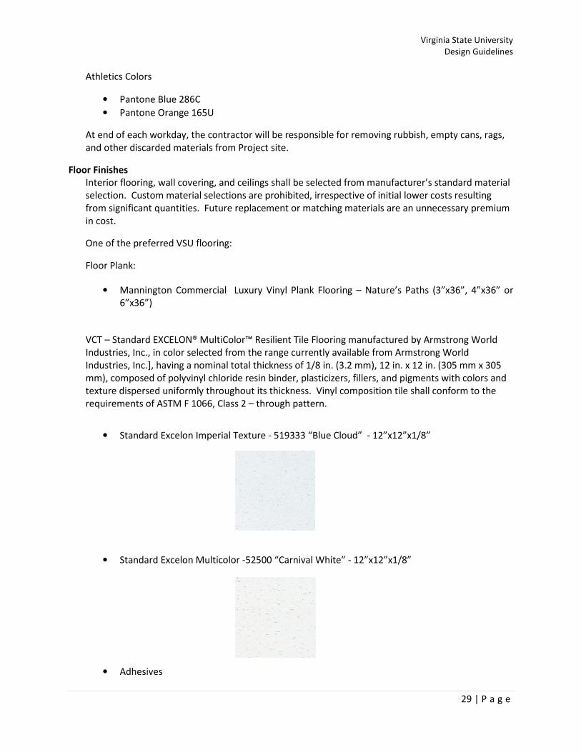
• Standard Excelon Imperial Texture - 519333 “Blue Cloud” - 12”x12”x1/8”
• Standard Excelon Multicolor -52500 “Carnival White” - 12”x12”x1/8”
• Adhesives

Virginia State University
Design Guidelines
30 | P a g e
A. For Tile Installation System, Full Spread: Provide Armstrong [S-515][S-525][S-700][S-
750] Resilient Tile Adhesive under the tile and Armstrong S-725 Wall Base Adhesive
at the wall base as recommended by the flooring manufacturer.
B. For Tile Installation System, Tile On: Provide Armstrong [S-515] S-525][S-750]
Resilient Tile Adhesive under the tile over smooth, completely bonded existing
resilient flooring and Armstrong S-725 Wall Base Adhesive at the wall base as
recommended by the flooring manufacturer.]
C. For Tile High-Moisture Installation Warranty, Full Spread: Provide Armstrong [S-
515][S-525] Resilient Tile Adhesive under the tile and Armstrong S-725 Wall Base
Adhesive at the wall base as recommended by the flooring manufacturer.]
Concrete Floor
All exposed concrete floors shall be sealed. Provide a sealer hardener in high-traffic areas.
Ceramic Tile
Ceramic tile floor and base shall be used in restrooms and showers with non-slip floor surfacing.
Detailing shall minimize moisture penetration to concrete substrate.
Cement backer board shall be used in all metal stud partition systems.
The detailing on the construction documents shall include a membrane type moisture barrier, which
shall minimize moisture penetration to substrate and/or metal studs.
Resilient Base
The standard resilient base in the University’s facilities is a heavy-duty vinyl or rubber base with a
minimum height of 4”. For all areas subject to heavy-wheeled equipment traffic or frequent
maintenance buffing equipment, the minimum height shall be 6”.
Outside corners shall be specified as pre-molded.
One of the preferred office bases:
• Mannington Commercial 915 Forest, Premium Edge (Type IP-rubber or Mannington Edge
Type TV- Vinyl)
Carpet
Carpet tile will be used in all academic building offices. Residence Halls will only use carpet in
Resident Educators offices.
The University does not allow carpet to be installed in basement areas in any building.

Virginia State University
Design Guidelines
31 | P a g e
One of the preferred office carpets:
• Mannington Commercial Cobb (Halftime/Gametime III), Texture-Twist Loop, Broadloom
Backing
Ceiling Finish
Suspended Acoustical Tile:
The use of fire-rated ceiling/floor assemblies requiring hold-down clips is prohibited unless there is
no other reasonable, economical solution to achieve the required assembly rating.
Access to all utilities above the ceiling shall be provided regardless of ceiling type used. Access
panels shall be shown on the Contract Documents.
END OF SECTION

Virginia State University
Design Guidelines
32 | P a g e
DIVISION 10 – SPECIALTIES
Fire Extinguisher Cabinet & Extinguishers
All fire extinguisher cabinets shall have the UL Rating visible on the inside of the cabinet.
Fire extinguishers shall have the current inspection label.
See VSU’s Safety Handbook for additional information.
Interior Signage
Toilet Accessories
Hand Dryers in all public spaces shall be Dyson Airblade model AB 02 or AB 04
Wall & Corner Guards
Wall and corner guards are required in corridors in all buildings and other areas where service carts,
moveable equipment, beds, and such similar equipment will typically be used.
Fire Caulking
For all fire rated walls, corridors, those are shown on the contract drawings. All penetrations in
walls, ceilings, decks, floors need to be fire caulked using approved fire caulking.
END OF SECTION
Virginia State University
Design Guidelines
33 | P a g e
DIVISION 11 - EQUIPMENT
END OF SECTION

Virginia State University
Design Guidelines
34 | P a g e
DIVISION 12 - FURNISHINGS
VCE as a mandatory source
Waiver Request and approval
Exemption Request
END OF SECTION

Virginia State University
Design Guidelines
35 | P a g e
DIVISION 13 - SPECIAL CONSTRUCTION
END OF SECTION

Virginia State University
Design Guidelines
36 | P a g e
DIVISION 14 - CONVEYING SYSTEMS
Elevators
The University prefers to use Machine Room Less Elevators for all new construction projects.
Machine-Room less (MRL) Elevators shall be designed to use steel suspension ropes not less than
9.5 millimeters in diameter. (See DEB Notice 051811 dated 5/18/2011)
Manufactures
• KONE –Mono Space Mid Rise Elevator. Min 4000 lbs
• http://www.kone.us/elevators/monospace/default.aspx
Elevator Key Boxes
Elevator Fire Service Key Box shall be Vator FSKB-SI2
Box has red powder coat finish with stainless steel door. Door is printed "EMERGENCY USE ONLY"
in black. Standard box depth is 1-3/8" D, or 2" Deep and flush mount with 1" frame.
END OF SECTION
Virginia State University
Design Guidelines
37 | P a g e
DIVISION 15 – MECHANICAL
Variable Frequency Drive
The University prefers the use of Variable Frequency Drives (VFD) installed in new construction or
retrofit projects. Below is a list of the preferred brands:
• Allen Bradley Drives
• Eaton/cutler hammer drives
• Danfoss drives/ Westinghouse drives
Variable Frequency Drive Requirements
• Indoor type 12 dustproof enclosure not installed in air stream
• Outdoor NEMA 3R enclosure within line of site of unit. (Noise filter)
• Backnet configuration
• Line surge and single phase protection:
Variable Frequency Drive Status & Alarm Handling
VFDs must provide running status and alarms to the BAS. All VFDs, including those built into or
included in installed mechanical systems, must meet this stipulation and include all relevant BAS
interlocks.
VFD Status will be reported to the BAS and displayed on the relevant equipment’s page in the
graphical Front-End.
Statuses passed to the BAS must include:
• Running Speed
• Running Mode (Hand/Off/Auto)
• Power Usage
Alarms will be collected on an Alarm reporting page accessible through the graphical BAS Front-End.
Alarms passed to the BAS must include:
• BAS Communication Failures
• Electrical Service Abnormalities
• Phase Failure
• Motor Overload
• Interlock for freezstat
• smoke detector interlock (sample tube external of ductwork)
Explicit Basis of Design
A basis of design (BOD) must be stipulated for all major equipment installed on the job, including
but not limited to:
• Chillers
• Pumps
• Cooling Towers
• Air Handlers
• Energy Recovery Systems

Virginia State University
Design Guidelines
38 | P a g e
• Major Fans
• Terminal Units
Owner Training
Training shall not be conducted until after all functional testing of the equipment is completed
unless given written authorization by the owner. Failure to comply with this requirement will result
in the repetition of the training session at no additional cost to the owner.
Warranties and Extended Warranties
Asset List (Maximo)
Attic Stock
END OF SECTION

Virginia State University
Design Guidelines
39 | P a g e
FIRE PROTECTION & STANDPIPE
Fire Pump Necessity Tests
Before the fire suppression system is designed, water flow and static pressure tests should be
performed in order to determine the necessity of a Fire Pump. Pressure and flow testing shall be
coordinated with Capital Outlay’s Project Manager, VSU’s Safety Officer and verified with
Chesterfield County Utilities.
Victaulic Pipe Permissible
Victaulic pipe may be used for the construction of the mains in fire suppression systems and must be
accessible. Branch line construction methods will be at the discretion of the Design Build Team and
the Owner.
Concealed-Type Sprinkler Heads
Whenever possible, Sprinkler Heads will be of a concealed design.
Fire alarm Pre-testing verification will be a part of the project under the scope of the Owner’s
Commissioning Representative.
Sprinkler Head Guards
Sprinkler heads in areas in high traffic areas (near roof access ladders, in gymnasia, etc.) must have
guards to prevent accidental contact from setting them off.
END OF SECTION

Virginia State University
Design Guidelines
40 | P a g e
PLUMBING
Victaulic Exclusion
It is the Owner’s policy that Victaulic pipe may not be used in hydronic OR OTHER systems that are
subject to large temperature changes. Dual temperature hydronic systems in particular must not be
constructed with Victaulic pipe.
Victaulic terminal connections to major equipment are permissible for ease of maintenance and
replacement.
Victaulic pipe may be used in fire suppression systems as is customary.
Dual Mode Flushing Toilets
In the interest of conserving water, whenever possible, provide dual-mode flushing toilets.
Comprehensive Insulation
All liquid transfer pipes like hydronic, domestic, hot, cold, and otherwise, must be insulated in an
appropriate manner.
VSU does not accept elastomeric pipe insulation. Change to fiberglass pipe insulation
Coil and Bypass Flow Control
Whenever hydronic water flow through a device is controlled with a three-way valve, any auto-flow
valve or control device regulating flow on that device will be placed on the return common to both
the coil and the bypass pipe, ensuring that the water flow is balanced under all conditions of the
valve operation.
Detachable Terminal Unit Coil Connections
When connecting a terminal unit to hydronic mains, always provide the means to detach the
connecting devices (control valves, flex hose, auto-flow devices, bypasses, strainers, etc.) from both
the hydronic piping and the coil. This allows these devices to be worked on at ground level and
permits their easy replacement.
The unions shown in the accompanying graphic represent any device, which can be easily and totally
disconnected. Flex hoses with standard connector ends are permissible for this application.
Automatic Air Vent Placement
Place automatic air vents on each local maximum in each hydronic system. Local maxima serve as
traps for air introduced through maintenance work or normal operation. These trapped air pockets
can prevent hydronic systems from functioning appropriately.

Virginia State University
Design Guidelines
41 | P a g e
Local maxima can occur:
• Inside mechanical rooms
• When pipes exit the tops of chases
• Inside AHU dog houses
• When branches depart mains
All Automatic Air Vents must have a ball valve for service
installed along with the AAV.
Mechanical Pipe Labeling
Mechanical piping shall be labeled as follows:
• In accordance with applicable ANSI Standards.
• With permanent, color-coded plastic markers.
• Markers no more than 20 feet apart.
• Within 5 feet of a valve on every pipe entering or leaving it.
• Indicating direction of flow.
• Making distinction primary and secondary circuits.
The following matrix summarizes desired labeling colors:
Service Color
Chilled Water Blue
Condenser Water Green
Hydronic Hot Water Orange
Steam Red
Figure 1 - Detachable Terminal Coil Connections
Figure 2 - Local Maxima

Virginia State University
Design Guidelines
42 | P a g e
BAS Device Ceiling Grid Marking
The following BAS devices must be labeled on the ceiling grid below them when they are mounted
above the ceiling:
Device Mark
CO2 Blue Dot with White X
Chilled Water Valve Blue Dot
Hydronic Hot Water Valve Orange Dot
Steam Valve Red Dot
END OF SECTION
Virginia State University
Design Guidelines
43 | P a g e
HEATING, VENTILATING, and AIR CONDITIONING
Indoor Air Quality
When possible and appropriate, include the following methods to achieve good indoor air quality:
• High performance filtration (MERV rating minimum 8, preferably 13)
• Carbon-Dioxide monitoring and control
• Carbon Monoxide detection and control in areas with combustion Equipment
• Refrigerant Monitoring and control when suitable in areas with refrigeration equipment
• Ionization of supply air
Energy Recovery Ventilation
Energy Recovery Ventilation improves the energy-efficiency of an air handling system by “pre-
conditioning” incoming outside air with heat from exhaust airflows. When possible and appropriate,
include the following to achieve energy recovery ventilation:
In order of preference:
1. A cross-flow air-to-air sensible heat exchanger
• These devices have no moving parts and are very low maintenance.
2. A rotating enthalpy wheel
• These devices have moving parts but are very effective when maintained properly.
3. A hydronic “run around” coil
• These devices have moving parts (pumps) and must be kept filled with heat transfer
fluid (water / glycol). They save more energy than they use when controlled
properly.
Minimal Outside Air Duct Length
The length (and resultant static pressure buildup) of all outside air ductwork must be kept to a
minimum (below 10’ if at all possible). When it is necessary to separate exhaust outlets and outside
air intakes, err on the side of extending exhaust ductwork rather than displacing outside air intakes.
Energy Metering Devices
In order to carefully analyze the energy usage of the building, there must be a way of collecting data
on the usage of individual devices. Whenever possible, include individual energy monitoring
capabilities on:
• Variable Frequency Drives
• Pumps
• Chillers
• Air Handlers
• Split-System Refrigeration units
• Boilers
• Water Heaters
• Energy Recovery Ventilators
• Fans
• Fan Coil Units
• Cooling Towers

Virginia State University
Design Guidelines
44 | P a g e
Duct Air Leakage Testing
Duct Air Leakage Testing (DALT) verifies that ductwork is suitable for carrying the air that it must at
the appropriate pressure without unacceptable leakage. This is a necessary verification step,
especially in the case of ductwork that will be sealed into shafts.
Perform DALT under the following conditions:
• Location of DALT test points will be at the discretion of the Owner’s representatives or
agents.
• System readiness for DALT testing will be determined by the Owner’s representatives or
agents.
• Duct Leakage Classes, pressure classes and seal classes will be determined by the design
build team in collaboration with the Owner.
Outdoor Air Coil Freeze Protection
Coils that are exposed to outside air must be protected from freezing. When possible and
appropriate, include the following to achieve coil freeze protection:
In order of preference, but not mutually exclusively:
1. Propylene Glycol Solution Heat Transfer Fluids
• Propylene Glycol is relatively non-toxic and provides a passive method of preventing
coil freezing by decreasing the freezing point of the heat transfer fluid.
• The concentration of Propylene Glycol in the system must be maintained at all times
at a minimum of 20% by volume as read by a refractometer. Install systems to
ensure that this concentration is maintained.
2. Circulation Pumps and Associated Control Sequences
• Circulating the heat transfer fluid through the coil during freezing conditions makes
it more difficult to freeze. This active method requires that the freeze-protection
circulation pumps operate under proper control. Freeze protection pumps are
piped parallel to system and powered from the emergency generator.
3. De-Frost Control Sequences
• Periodic stoppage or reduction of the outside airflow through the coil gives the coil
time to defrost. This active method requires that the unit be under proper control.
Heat Trace
Any pipe exposed to the outdoors must be wrapped with insulation and provided with radiant
heating elements (heat trace) that will activate during low temperature conditions to prevent
freezing. If there is a Building Automation System, IT must display the status of the heat trace and
produce an alarm if it does not function appropriately.
Heat trace thermostats must be located outside of the air plumes of any exhaust or relief discharges
and powered from the emergency generator circuit.
XY Plane Coil Connections on RTUs
Any pipe penetrating the envelope of a piece of roof-mounted air moving must do so on the XY
plane after having penetrated the roof separately from the unit. Connections on the z axis of the
unit, whether through the bottom of the unit or in a dog house next to it, are not acceptable. This
requirement is due to protracted problems with sweating pipe over non-weatherized attic spaces.

Virginia State University
Design Guidelines
45 | P a g e
Filter Change Data
For each piece of equipment, provide the following in a single, collated document in the operations
and maintenance manual:
• Number of Filters
• Type of Filters, including MERV rating, size and connections, if applicable
• Filter Change Schedule
• Conditions under which filters must be changed
o Exceeding a set differential pressure across the filter bank
o Contamination of HEPA filters - include bagging procedures and supplies if
applicable
Water-Shedding Outdoor Insulation
Insulation on outdoor ductwork must be installed such that water is prevented from collecting on
top of it.
Appropriately Pinned Insulation
Whenever ductwork is insulated, this insulation must be affixed to the ductwork securely on all
surfaces in accordance with applicable SMACNA guidelines.
Sized to Return the Space to Control
The air handling system must be capable both of maintaining an already under-control building at its
target temperature economically, AND bringing a building which has operated outside its ordinary
conditions under temperature and humidity control rapidly. This means that the system will need to
be able to recover itself even after the system has been off or the doors have been forced open for
extended periods.
Designed for Heat Wheel Replacement and Maintenance
Any air handler that contains a heat wheel must be constructed such that the heat wheel can be
easily replaced without damaging the unit or endangering those performing this task.
Total BAS Integration
Air Handling Units must have a control system that allows total integration (monitoring and
modification of most control points) with the BAS. Simply being able to view the ERU alarm points
and sensor readings is not sufficient. AHUs that are designed to be stand-alone must also be
capable of total control by the BAS.
END OF SECTION

Virginia State University
Design Guidelines
46 | P a g e
DIVISION 16 - ELECTRICAL
Site Lighting – General
Lighting is an important element in security design. An effective security lighting design should
consider all element of the site: facility location and usage, the landscape or planting plan and site
walkways and traffic patterns as well as the impact of lighting on the surrounding areas.
The A/E is to provide Point-by-Point foot-candle calculations of the site lighting and voltage drop
calculations for site lighting circuits with the contract document submission.
All exterior lighting fixtures shall be full cut-off pole mounted fixtures and low-level bollards,
designed to meet Illumination Engineering Society (IES) standards for cut-off optics, unless
otherwise directed.
All exterior areas 25’ from the building, parking lots, in addition to egress pathways shall be 1.0
horizontal foot-candle (fc) uniform lighting level.
Building mounted lighting shall be provided at exit discharges and service areas. The fixtures and
poles shall be painted matte black.
Luminaires
The University has developed a standard light from Architectural Area Lighting www.aal.net.
Luminaires shall comply with UL 1598 and be listed and labeled for installation in wet locations by
an NRTL acceptable to authorities having jurisdiction.
MANUFACTURES:
1. Architectural Area Lighting “Providence Medium” (PROV-H3 or H5)
2. Architectural Area Lighting “Providence Medium LED” (T3-60 LED BW, T2-60 LED BW)

Virginia State University
Design Guidelines
47 | P a g e
Lamps and Ballast
The University utilizes two types of Lamps:
• HID Ballast, Include the following features unless otherwise indicated. Ceramic, Pulse Start,
Metal Halide, minimum CRI (80), and CCT color temperature (4,000K).
• LED MicroEmitter with a tempered glass lens, sealed with an extruded silicone gasket held
by stainless steel fasteners. Comply with UL 1598 for outdoor, wet location. Color
temperature 5,000K.
Voltage shall be 208/277 for all exterior lighting fixtures
Light Poles
The University requires decorative poles either round or fluted and three different heights (12’, 16’,
and 25’) depending on the location of the pole. All poles are Aluminum, 4”-5” diameter cast
aluminum #356 alloy.
Grounding and Bonding Lugs welded ½ inch threaded lug for attaching grounding and bonding
conductors of type and size required.
• Pole Height for sidewalks 12’
• Pole Height for sidewalks adjacent to roadway 16’
• Pole Height for parking lot 25’
Manufacturer:
• Architectural Area Lighting model “DB -3, DB-6 or DB-10”
• NAFCO International, Fond du Lac, WI 1-800-558-4810 model “Washington”.
DB-1 DB-3 DB-6 DB-10

Virginia State University
Design Guidelines
48 | P a g e
Light Bollards
The University prefers the Providence Series LED light bollard.
Acceptable Manufacture
• Architectural Area Lighting
36 LED-WW (3,500k), IES Type 5, 277 volt
Site Lighting – Foundation
The University utilizes two different light pole foundations, based on the height and location of the
light pole. Pole foundation outside of VSU right-of-way should utilize VDOT Standards. Poles should
never be erected without the luminaire installed.
Occupancy Lighting Controls
Whenever possible, include occupancy sensors and tie them into the lighting systems in order to
conserve energy. Follow these guidelines when installing occupancy lighting controls:
• Occupancy lighting controls may or may not be under BAS control or monitoring. When
lighting will be under BAS control, occupancy sensors and lighting systems must be provided
with any necessary interlocks.

Virginia State University
Design Guidelines
49 | P a g e
• Occupancy sensors must be sufficiently sensitive to not turn off when a person is calmly
working in the room.
• Attic, mechanical, and common spaces should be provided with occupancy-sensing systems
to ensure cutoff when not in use.
Day-Lighting Control
Day-lighting control allows lighting systems to burn only when necessary: then the building is in use
to supplement or replace natural light.
Specify external light fixtures that ensure lighting cutoff during daylight, regardless of their
attachment to an external control system. This functionality may be provided via a timer or
photocell.
Dedicated BAS Power & UPS
The BAS must have its own power circuit, independent of any other device. This power shall be
backed up with an Uninterruptable Power Supply (UPS) to ensure operation for no less than 6 hours
without external power, connected to generator if available.
BAS Lighting Control
Whenever possible, lighting systems should be controlled through the BAS rather than through an
independent lighting control system. This limits the number of interfaces that users must learn.
BAS lighting control also facilitates remote monitoring and centralized control of campus lighting.
Power
Energy metering will be required on all new construction and renovation projects and shall be
capable of reporting through the BAS system.
END OF SECTION

Virginia State University
Design Guidelines
50 | P a g e
DIVISION 17 - BUILDING AUTOMATION
Integrated Automation
Control Point List Development
VSU and the commissioning representative will create a document, listing the specific minimal set of
control points for the project. This document’s contents will be considered necessary for producing
an acceptable Building Automation System. This minimal point list does not define the entire extent
of the BAS system, which the controls contractor must submit.
The Mechanical Design Build Team (DBT) will be provided the OPR and the minimal set of BAS points
before the control system is designed and submitted. The DBT will expand this list to include those
points perceived as necessary to meet the specific requirements of the project systems and to
minimize service calls.
This preliminary DBT point list will be used as a starting point for BOD (Basis of Design) discussion. A
Basis of Design will be decided upon after the preliminary DBT point list has been reviewed and
edited to conform to the OPR (Owner’s Project Requirements).
BAS Front – End Design
The BAS Front-End is the control interface for the Owner. As such, it must be clear, easy to use, and powerful.
The following requirements must be met by any installed or retrofitted BAS system installed for the owner:
• Graphical User Interface
• Graphic Mockups for one of each type of equipment and each screen type must be
submitted for consideration by the bid date.
• When there is a pre-existing map for BAS control of multiple facilities, establish a hyperlink
from this map to this building’s BAS interface.
• Provide a graphing utility capable of producing clearly legible graphs and PDF output of each
quantity logged by the BAS, including but not limited to those depicted on any educational
“Dashboards”. This output is necessary for correspondence and troubleshooting.
• Sequences of operation - as refined by the Design-Build Team - should be included on the
BAS Front-End graphic screens. The sequences should include:
o Design energy usage for comparison to operating data
o A list of possible alarms and/or a key for deciphering alarm codes
o A list of self-diagnostic or warm-up behaviors of the displayed equipment, including
wait times before normal operation or control is restored.
• Accessory protection devices - these should be monitored and displayed through the BAS,
including:
o CO2 Sensors (display status, alarm above a threshold value)
o Co Sensors (display status, alarm above a threshold value)
o Heat Trace Status (display status, alarm if non-functional)
o Filter Differential Pressure (display status, alarm above a threshold value)
• Other devices monitored and displayed through BAS
o Fan speed of any motor driven by a Variable Frequency Drive which moves over
3000 CFM
Virginia State University
Design Guidelines
51 | P a g e
Residence Hall Terminal Unit Control
In Residence Hall applications, VSU would like to enable the student to command the Terminal Unit
associated with his/her room on and off and, perhaps, adjust fan speed. This could permit the
students to shut off the unit when opening a window.
The Terminal Unit’s display on the BAS Front-End should include:
• A rolling average percentage of time that the unit is off
• A rolling average space temperature setting
Thermostat Covers
Thermostats will have clear tamper proof lockable covers and should be of one consistent type in
all public spaces.
BAS Front – End Terminal Unit Indicator Colors
All Terminal Units must be tied to the BAS.
The BAS frontend graphics shall indicate the state of Terminal Units by the following color codes:
• Red – Space served by FCU is above set point tolerance.
• Blue – Space served by FCU is below set point tolerance.
• A Color To Be Determined by the Owner – The Terminal Unit is commanded off.
Chiller Control Strategy
The Design Build Team will provide the conditions under which the Chiller will be activated. These
conditions may include the number of units calling for cooling and/or the total volume of chilled
water required.
Hot Water Reset Control Strategy
Process Hot water temperature should adjust its temperature based on outdoor conditions. Higher
hot water temperatures will be required for colder outdoor temperatures and vice versa.
Alarm Handling
Alarms transmitted to or generated by the BAS shall be transmitted to Central Physical Plant, with a
robust backup strategy for alarm history. Under the warranty period, these alarms shall be
transmitted to:
• The Alarm History Page for storage.
• The Owner of the building (VSU).
• The contractor who installed the system.
• The Owner’s Commissioning Agent.
Rainwater Irrigation Control
When implementing control of the rainwater irrigation system, build in the following considerations:
• Irrigation controllers shall prohibit system from operating while raining.
• Rainwater irrigation shall not run when the cistern is empty. Domestic water could be used
to make up for this deficit.
Data Backup
A robust data backup strategy must be included in the BAS package. This strategy must protect the
following:

Virginia State University
Design Guidelines
52 | P a g e
• BAS Programming and Set Points
• Alarm Records
• Performance Data
Educational “Dashboard” Contents
The Educational “Dashboard” is a tool that allows the occupants of a building to understand their
effects on the mechanical operation of the building. The information displayed is pulled from the
BAS. Installation of a “Dashboard” is counted toward LEED educational credit 2.5.
When establishing a “Dashboard” the following considerations apply:
• Quantities that must be tracked and displayed daily, weekly and monthly in order to meet
the LEED requirements include the following:
o Power Usage Totals
o Water Usage Totals
o Temperature
o Relative humidity
• Quantities to be tracked daily, weekly and monthly in the interest of running the facility well
include the following:
o Overall Room Occupancy (information about individual rooms must not be
displayed)
o Rain water/gray water cistern level and Flow (if any)
Educational “Dashboard” Interactivity
Interactivity is key in engaging and educating the building occupants. The following solutions are
stated in order of preference:
• A fully interactive interface that allows building occupants to satisfy their curiosity about the
performance of the building to the maximum extent desired by the Owner. This exploration
shall be possible in a self-guided manner as well as through a default loop of automatically
rotating, pre-determined screens/metrics.
• A slightly interactive interface that allows accelerated movement around a loop of
automatically rotating, pre-determined screens/metrics.
• A non-interactive loop of automatically rotating, pre-determined screens/metrics.
Owner-Provided Static IP Addresses
Static IP addresses will be assigned by the Owner’s IT department for each device, which requires
one. The BAS contractor will work with the Owner’s IT department to establish an acceptable
network architecture (including layer 3).
It is preferable to set up sub-networks in each building that then report to a central network (Layer 3
Network architecture).
Humidity Tracking, Sampling Locations and Dehumidification
The HVAC and control systems must be designed such that they can monitor and control the
humidity in the space, even when the building is not running in occupied mode.
Humidity sampling can be done from building return/exhaust air ONLY if the return/exhaust being
sampled is not from bathroom or locker room areas. If all return/exhaust is being pulled from

Virginia State University
Design Guidelines
53 | P a g e
bathroom/locker areas, there must be sensors in each partition of the building (at minimum in each
hallway on each floor) in order to sample the temperature and humidity of the space.
Mandatory Unoccupied Operation Mode
All buildings (including those with “24-7-365” schedules) will be presumed to have not only night
setback modes, but also unoccupied modes.
Unoccupied Humidity Control
An unoccupied mode will maintain the temperature and humidity characteristics required by the
most recent LEED standard during an IAQ purge OR below the growth conditions of mold, mildew,
and fungi in buildings (including a safety factor), whichever is most stringent.
END OF SECTION

Virginia State University
Design Guidelines
54 | P a g e
COMMUNICATIONS
All new and renovation projects must considered IT Networking and Audio Visual (A/V)
requirements. The Office of University Technology has developed a standard guideline for all
university data, equipment and main distribution rooms for new construction. Please refer to the
OIT design guidelines.
The following is an example of a typical equipment room or main distribution frame layout.
Figure 1 - Example of a ER/MDF
ERs and MDFs may not be inside of or be part of a Mechanical space, Equipment room, Washroom,
storage area, janitor closet. All room locations must be approved in writing by the Office of
University Technology prior to design.
Access
Access to the Rooms shall be 24 hours-per-day, 365 days-per-year basis (24x7). Access shall be
through common use corridors and not accessed by way of any other room. All doors must be on
the approved VSU Access Control System.
Heating, Ventilation and Air Conditioning (HVAC)
Continuous operation HVAC shall be available on a 24 hours-per-day, 365 days-per-year basis. A standalone unit should be
considered for all Rooms.
Standby operation If a standby power source is available in the building, consideration should be given to also
connecting the HVAC system serving the Communications Rooms to the standby supply.
Virginia State University
Design Guidelines
55 | P a g e
Equipment 110V Outlets
ERs / MDFs shall be equipped with a minimum of six (6) dedicated 110V, 20A circuits. Outlets shall
be 110V, 20A duplex outlets designed for twist-lock plugs. Outlets may be wall mounted, installed in
divided surface raceway, or installed on Kindorf channel above equipment racks depending on room
configuration. Outlets shall be installed 16" from finished floor to center. All outlets shall have a
laser printed circuit identifiers affixed to it indicating the panel room number, panel ID, and circuit
number. Office of University Technology may specify additional outlets on a case-by-case basis.
Convenience 110V Outlets
ERs/ MDFs shall be equipped with convenience outlet placed on each wall of the TR for uses other
than network equipment (i.e. power tools, testing equipment). This outlet shall be run from a
separate electrical panel. All outlets shall have a laser printed circuit identifiers affixed to it
indicating the panel room number, panel ID, and circuit number. The Office of University
Technology may specify additional outlets on a case-by-case basis.
END OF SECTION

Virginia State University
Design Guidelines
56 | P a g e
ELECTRONIC SAFETY and SECURITY
Access Control System
The VSU standard for the Access control system is the Software House, I-Star system with Mifare II
multi readers. The system must be fully integrated with the CCTV system and Fire Detection System.
All I-Star panels are housed in the MDF/IDF areas and will have enough battery power to last a
minimum of 1 hour.
Exterior Door Security Card Readers
Security card readers interfacing with the Owner’s security system should be installed whenever
practicable at exterior doors that open from the outside.
Interior Wing or Pod Door Security Card Readers
If the building has separate wings, pods, or modules, access to these areas may also be controlled
with security card readers.
Security Cameras
The VSU standard for the security cameras (CCTV) is the American Dynamics Intellex system, which
must be integrated with the Software House I-Star panel. Camera deployment must cover all
building egresses, hallways, and stairwells, insuring complete coverage of all traffic flow.
Egress Locks
All egress Residence Life egress doors shall be equipped with delayed egress locks. The preferred
manufacture is MagForce 390DEL
The 390DEL Series Delayed Egress Locking System is a self-contained unit, designed to meet
NFPA 101 Life Safety Code and BOCA, while providing ongoing access controlled security.
This easy to install, cost effective solution provides the highest access security and safety.
The 390DEL delayed egress is triggered by an internal “plunger switch” to initiate a 15
second delay and audible alarm before unlocking and can be triggered by external contacts
such as an electrified exit bar or request to exit device. The 390DEL utilizes an on board
iButton Reader to provide reset and legal release.
Sequence of Operation- Emergency Exit
• The lock will release with the following conditions- 1.Actuation of the automatic
sprinkler system or fire detection system, 2. Loss of power controlling the lock or lock
mechanism, 3. Signal from the fire command center, 4. Manual release through the
access control system software or by a legal card read or other control input.
• The 390DEL will release when a force applied to the exit door of not more than 15 lbs
is applied for 1 second. This action initiates an irreversible process that releases the
magnetic holding force of the lock and activates the audible alarm in the lock.
• Once the 390DEL releases, a manual reset is required to reset the lock to its previous
secure state.
END OF SECTION

Virginia State University
Design Guidelines
57 | P a g e
EXTERIOR IMPROVEMENTS
While the University respects the artistic freedom inherent in the Architectural design process, it
requires that all designers work within the traditional pattern of the Campus.
A color schedule for all exterior materials shall be submitted for approval by the Campus Architect at
the preliminary design phase.
Exterior Building Colors
Quad I
• Brick Field – Lawrenceville Modular 102
• Brick Black Accent – Lawrenceville Modular 023
• Brick Mortar – Gray to match New Science Building
• Precast – Stafford Stone Works Color 261
• Shingles – CertainTeed Hatteras Shingles in Windswept Gray
• Composite Wall Panels – Reynobond Bone White
• Cornice Sheet Metal – Sentriclad New Bone White
• Downspouts – Sentriclad Medium Brown
• Brick Expansion Joint – Dow Corning 790 “Rustic Brick”
• Precast Expansion Joint – Down Corning 790 “Precast White”
• Storefront and Curtain Wall – Kawneer Bone White
• Storefront and Curtain Wall Insulated Spandrel Panels – Mapes Bone White
• Unit Pavers – Pine Hall Brick Pathway Full Range Traditional Edge Paver
Quad II
• Brick Field – Lawrenceville Modular 102
• Brick Black Accent – Lawrenceville Modular 023
• Brick Mortar – Gray to match New Science Building
• Precast – Stafford Stone Works Color 261
• Shingles – CertainTeed Hatteras Shingles in Windswept Gray
• Composite Wall Panels – Reynobond Bone White
• Cornice Sheet Metal – Sentriclad New Bone White
• Downspouts – Sentriclad Medium Brown
• Brick Expansion Joint – Dow Corning 790 “Rustic Brick”
• Precast Expansion Joint – Down Corning 790 “Precast White”
• Storefront and Curtain Wall – Kawneer Bone White
• Storefront and Curtain Wall Insulated Spandrel Panels – Mapes Bone White
• Unit Pavers – Pine Hall Brick Pathway Full Range Traditional Edge Paver
Gateway Dining and Events
• Brick A – Lawrenceville Modular 212
• Brick B – Lawrenceville Modular 373
• Brick Mortar – Essroc C-223
• Precast – Seaboard Concrete Products #7105 Dover White with Machine Honed Finish

Virginia State University
Design Guidelines
58 | P a g e
• EIFS Ceiling at Balconies – Masterwall #108 Burris White
• Shingles – Timberline in Oyster Gray
• Metal and Downspouts – Sentriclad Bone White
• Storefront and Windows – Efco Bone White
Brick Walkways and Ramps
Brick walkways patterns shall be constructed and installed per the guidelines shown in Fig. 35.3.1 –
BRICK LANDSCAPE WALK.
Fig 35.3.1 – BRICK LANDSCAPE WALK

Virginia State University
Design Guidelines
59 | P a g e
The University has adopted and modified VDOT’s Brick Sidewalk Ramp. Brick ramps shall be
constructed and installed per the guidelines shown in Fig 35.3.2 – BRICK SIDEWALK RAMP
FIG. 35.3.2 – BRICK SIDEWALK RAMP- MODIFIED VDOT CG-12 (SECTION
Detectable Warning Paver shall be Pine Hall Brick Tech Bullet #3 – Tactile Paver. It satisfies the
ADAAG Requirements for 4.29 - Detectible Warnings as required by 4.1 – Minimum Requirements
and 4.7 – Curb Ramps. See Fig. 35.5.1 – SIDEWALK RAMP WITH DETECTABLE WARNING for
installation guidelines.
FIG. 34.5.1 – SIDEWALK RAMP WITH DETECTABLE WARNING PAVERS

Virginia State University
Design Guidelines
60 | P a g e

Virginia State University
Design Guidelines
61 | P a g e
Concrete Bollards
The University utilizes fixed Bollards to control vehicular access in pedestrian zones and to protect
equipment for vehicular damage. On special circumstances, removable Bollards may be used.
Placement of bollards in pavement must consider how vehicles are controlled. All post shall
conform to current OSHA Standards
• Constructed of steel not less than 4 inches (102mm) in diameter and concrete filled.
• Spaced not more than four feet (1,219mm) between posts on center.
• Set with minimum of four stainless steel anchor bolts.
• Set with the top of the posts not less than 3 feet (914 mm) above ground.
• Located not less than three feet (914 mm) from the protected object.
•
All below ground bollards shall conform to the following:
• Constructed of steel not less than 4 inches (102mm) in diameter and concrete filled.
• Spaced not more than four feet (1,219mm) between posts on center.
• Set not less than three feet (914mm) deep in concrete footing of not less than a 15-inch
(381 mm) diameter.
• Set with the top of the posts not less than 3 feet (914 mm) above ground.
• Located not less than three feet (914 mm) from the protected object.
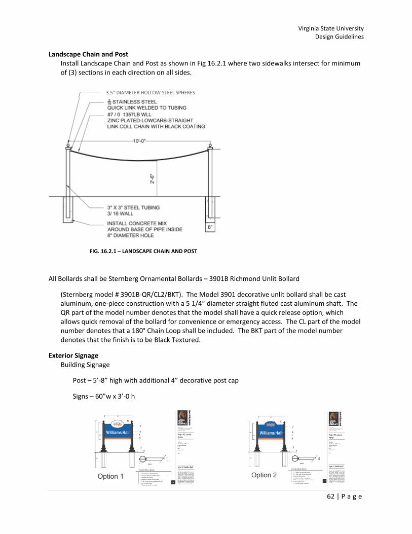
Virginia State University
Design Guidelines
62 | P a g e
3.5” DIAMETER HOLLOW STEEL SPHERES
Landscape Chain and Post
Install Landscape Chain and Post as shown in Fig 16.2.1 where two sidewalks intersect for minimum
of (3) sections in each direction on all sides.
All Bollards shall be Sternberg Ornamental Bollards – 3901B Richmond Unlit Bollard
(Sternberg model # 3901B-QR/CL2/BKT). The Model 3901 decorative unlit bollard shall be cast
aluminum, one-piece construction with a 5 1/4” diameter straight fluted cast aluminum shaft. The
QR part of the model number denotes that the model shall have a quick release option, which
allows quick removal of the bollard for convenience or emergency access. The CL part of the model
number denotes that a 180° Chain Loop shall be included. The BKT part of the model number
denotes that the finish is to be Black Textured.
Exterior Signage
Building Signage
Post – 5’-8” high with additional 4” decorative post cap
Signs – 60”w x 3’-0 h
FIG. 16.2.1 – LANDSCAPE CHAIN AND POST

Virginia State University
Design Guidelines
63 | P a g e
Directional Signage (wayfaring)
Post – 7’-0 high with additional 4” decorative post cap
Signs – 3’-6” wide x 6’-0 high
Directional Strips – 3’-4” wide X 4” high
Text Font
A FUTURAORTO FONT –Text on directional signs is 3” high
Student Parking Lot Signage
24”w X 18”h, color orange with blue lettering, Font 1-7/8” (top half) and 1” (bottom half)
Graphic Standards and Use of Logo

Virginia State University
Design Guidelines
64 | P a g e
Asphalt Paving
The University has adopted VDOT’s Asphalt Paving Guidelines and shall be constructed and installed
per the guidelines shown below:
END OF SECTION

Virginia State University
Design Guidelines
65 | P a g e
TURF AND GRASSES
The University’s grounds maintenance contract follows the guidelines in accordance with the
following;
• APPA- Association of Higher Education Facilities Officers.
• National Recreation and Park Association.
• Professional Grounds Management Society.
The contractor is prohibited from driving any vehicles or equipment on the existing turf or grass,
except when proper protection is installed.
University grounds that are disturbed or damaged as a result of the contractor’s operation shall be
replaced or repaired by the contractor at no cost to the University.
Maintenance projects or capital projects shall have the following requirements for new turf or
grasses:
• If irrigated, use top soil and sod
• If not irrigated, use 3-4 inches of high grade top-soil and hydro seed
END OF SECTION
Virginia State University
Design Guidelines
66 | P a g e
UTILITIES
Any contractor doing work on VSU’s campus must follow VSU’s Policy and Procedures when working on
existing campus utilities or when installing new utilities on campus.
No utilities on campus are to be abandoned in place. Electrical conductors, sanitary, sewer, gas lines are
to be removed.
Required Notice for planned Service Disruptions (Steam, water, sewer, power)
DVP service requests
Requests for Easements
Tracer wire/balls
Updating of master utility plans
Steam
Any building that uses steam to generate heating and hot water shall utilize steam condensate
pumps and not electric.
Insulation: For Direct buried, Underground repairs, Tunnels (new installation, repairs), Vaults, and
High, Medium, Low Temperatures, the University prefers to use the following type of insulation:
• Pour-in-Place Insulation (DriTherm )
• Pre-Cut Insulation System (DriWrap)
• Factory Applied Jacket System (DriClad)
o Installing contractor shall be responsible to install in accordance with
manufacturer’s published instructions for the specific application.
o Dritherm International Inc.
2500 Plaza 5
Harborside Financial Ctr.
Jersey City, NY 07311
www.dritherm.com
800-343-4188
Gas
The University prefers to use gas as the primary fuel source for emergency generators.
Water
The University water supply comes from Chesterfield County.
Virginia State University
Design Guidelines
67 | P a g e
Junction Boxes
All junction boxes installed in roadways and sidewalks shall be traffic rated.
END OF SECTION

Virginia State University
Design Guidelines
68 | P a g e
APPENDICES
List of State Forms
CO-7CM General Conditions Of The Construction Manager “At Risk” Construction
Contract (DGS-30-057)
GC-SWAM Supplemental General Conditions 51 (SWAM) (DGS-30-377)
CO-6a & 6b Statement of VUSBC Special Inspections (DGS-30-052)
CO-9 Contract between Owner and Contractor (DGS-30-064)
CO-9a Workers Compensation Certificate of Insurance (DGS-30-076)
CO-10 Standard Performance Bond (DGS-30-084)
CO-10.1 Standard Labor and Material Payment Bond (DGS-30-088)
CO-11 Contract Change Order (DGS-30-092)
GC-1 Change Order Estimate - General Contractor (DGS-30-200)
SC-1 Change Order Estimate - Subcontractor (DGS-30-204)
SS-1 Change Order Estimate - Sub Subcontractor (DGS-30-208)
CO-12 Schedule of Values and Certificate For Payment (DGS-30-104)
CO-13 Affidavit of Payment of Claims (DGS-30-108)
CO-13.1 Certificate of Completion by Architect/Engineer or Project Manager
(DGS-30-112)
CO-13.1a Architect/Engineer’s Certificate of Substantial Completion (DGS-30-116)
CO-13.1b Final Report of Structural & Special Inspections (DGS-30-120)
CO-13.2a Contractors’ Certificate of Substantial Completion (DGS-30-140)
CO-13.2 Contractors’ Certificate of Completion (DGS-30-136)
---------- Participation by Disadvantaged Businesses (DGS-30-360)
Reports For Information Only
Geotechnical Engineering Study
Hazardous Material Survey