· Web viewThe current density in windings shall be kept within 2.4 A/sq.mm. 8. FLUX DENSITY The...
123
TENDER FOR CONVERSION OF EXISTING 33 KV OH LINE (APPROX 10 KMS) UPGRADING EXISTING CONDUCTOR TO 100 SQMM AAA CONDUCTOR AS WELL AS CONSTRUCTION OF A NEW 4 POLE STRUCTURE WITH ASSOCIATED WORKS COMPLETE WITH SUPPLY, ERECTION, TESTING, & COMMISSIONING. FOR P/S TO NEW AUTO COMPLEX AT,MANIA. TANGI CHOUDWAR Estimated Cost : Rs. 44.3 lakh Time of Completion : 2 MONTHS Cost of tender paper : Rs. 10,000.00 EMD to be deposited with tender : RS. 45000.00 Date of sale : DT. 12.11.2007 TO 17.11.07 WITHIN 11 HOURS TO 13.00 HOURS Date of Submission : Dt. 21.11.07 UP TO 17 HOURS. Date of opening : Dt. 22.11.07 AT 15.30 No of Corrections: Page No 1 Signature of the Tenderer
-
Upload
vuonghuong -
Category
Documents
-
view
215 -
download
2
Transcript of · Web viewThe current density in windings shall be kept within 2.4 A/sq.mm. 8. FLUX DENSITY The...

TENDERFOR
CONVERSION OF EXISTING 33 KV OH LINE (APPROX 10 KMS)
UPGRADING EXISTING CONDUCTOR TO 100 SQMM AAA
CONDUCTOR AS WELL AS CONSTRUCTION OF A NEW 4 POLE
STRUCTURE WITH ASSOCIATED WORKS COMPLETE WITH SUPPLY,
ERECTION, TESTING, & COMMISSIONING. FOR P/S TO NEW AUTO
COMPLEX AT,MANIA. TANGI CHOUDWAR
Estimated Cost : Rs. 44.3 lakh
Time of Completion : 2 MONTHS
Cost of tender paper : Rs. 10,000.00
EMD to be deposited with tender
: RS. 45000.00
Date of sale : DT. 12.11.2007 TO 17.11.07 WITHIN 11 HOURS TO 13.00 HOURS
Date of Submission : Dt. 21.11.07 UP TO 17 HOURS.
Date of opening : Dt. 22.11.07 AT 15.30 HOURS
MR. No. & Date :
Issued to :
No of Corrections:
Page No 1 Signature of the Tenderer
ISO 9001& 14001 CORPORATION
ORISSA INDUSTRIAL INFRASTRUCTURE DEVELOPMENT
CORPORATION
Sir,
1. After careful examination of the above specification together with the general conditions referred therein, we hereby offer to supply, erect, test and commission the materials covered thereon complete in all respects as per specification and general conditions at the rate quoted in attached schedule of prices of the tender.
2. Our offer shall be valid up to 180 days from the date of opening of Price Bid of the tender.
3. We hereby undertake to have the materials delivered/ work executed within the time specified in the tender and to adhere to the quantity to be supplied at destinations to be prescribed by the owner.
4. We hereby guarantee the technical particulars given in the tender, supported with necessary test reports from concerned authorities.
5. We certify to have purchased a copy of the tender papers by remitting Rs._________ (Rupees _______________________________________) only by cash and this has been acknowledged by you in your money receipt No dated .
6. We agree to furnish the security deposit in the manner to be decided by your competent authority.
We remain.
Yours faithfully,
(Signature)(With seal)
Note: This form should be duly filled in by the tenderer and returned to the Divisional Head (Elect), IDCO Bhubaneswar - 751 022 along with the tender.
No of Corrections:
Page No 2 Signature of the Tenderer

Orissa Industrial InfrastructureDevelopment Corporation(A Government of Orissa Undertaking)IDCO Towers, Janpath, Bhubaneswar-751022Phones: (0674) 2542784, 2540820, Fax: 2542956Email: [email protected] ISO 9001 & 14001 CORPORATION
No. BBSR-ELECT/E-6258 / 07-08 / 3089 Date: 6.11.07
TENDER CALL NOTICE
1. Sealed tenders are invited from experienced and reputed HT Electrical contractors having valid license from the competent licensing authority, for the following works for P/S to new Auto complex Park at Mania, Tangi Choudwar in the dist of Cuttack.
2. The tender documents shall be issued to the firms on production of the following documents regarding fulfillment of eligibility criteria.a) The tenderer should have executed similar type of composite works in turn key basis of value not
less than 15 lakh during the last 5 years and should produce the successful completion certificate from the client such as Govt., PSU, registered society etc. Work experience as sub – contractor to the principal contractor will not be entertained.
b) Average annual turn over of Rs.1.00 crores or more during the last three years duly certified by Chartered Accountant (excluding current year).
c) Photo copy of valid EPF registration certificate, STCC/ITCC or PAN/TIN. 3. The bid documents with all details may be purchased from the office of the Divisional Head
(Elect.) from 12.11.2007 to 17.11.2007 (both days inclusive) between 11.00 hours to 13.00 hours on cash payment of non-refundable amount as indicated in the table below.
4. The tender document can also be downloaded from our Website at www.idcoindia.com. In that case the cost of the bid document shall be submitted along with the tender in the form of demand draft drawn in favour of “Orissa Industrial Infrastructure Development Corporation” payable at Bhubaneswar in a separate cover. The offer shall be considered only if the authority is satisfied about the fulfillment of eligibility criteria.
5. IDCO shall not be responsible for any delay/difficulties/inaccessibility of the down loading facility for any reason whatsoever, in case of any discrepancy between the tender documents down loaded from internet and the master copy available in the office, the master copy will prevail. No claim on this account will be entertained.
6. Bids must be accompanied with Bid Security (EMD) of the amount specified in the table below in manner prescribed in the tender document.
7. The sealed bid prescribing the name of the work as given in tender notice must be delivered to the office of the undersigned on or before 5.00 PM hours on dated 21.11.2007 by either register post/speed post only and will be opened on the next date at 15.30 hours in presence of the bidders or their authorized representative. If the office happens to be closed on the specified date, the bids will be received and opened on the next working day of office at the same time and venue. Non-receipt or delayed receipt of tender on any account shall be at tenderers risk.The authority reserves the right to accept or reject any or all offers without assigning any reason thereof.
Package No.
Name of the work Est. cost in Rs.
Bid security EMD (Rs.)
Cost of bid document
(Rs.)
Period of Completion
(1) (2) (3) (4) (5) (6)1. Conversion of existing 33 KV OH line (approx 10 kms)
upgrading existing conductor to 100 same AAA conductor as well as construction of a new 4 pole structure with associated works complete with supply, erection, testing, & commissioning.
44.3 lakhs 45,000.00 10,000.00 2 months
2 Construction of new 33 KV lin (7 KMs), one 6 pole structure & 1 no station Transformer with all associated
63 lakhs 65,000.00 10,000.00 2 months
No of Corrections:
Page No 3 Signature of the Tenderer

works complete with supply, erection, testing, & commissioning.
Yours faithfully Sd
Divisional Head (EL)
Memo No 3090 /Dt. 6/11/07
Copy forwarded to Jt.Manager (PR), IDCO, Bhubaneswar with a request for publication of the Tender Call Notice in any one largest circulated Oriya daily and national level English daily (Kolkata edition) for one day consecutive publications and wide publicity. The copies of the paper publication may please be furnished to this office for record. It is also requested to please include this tender call notice in IDCO Website for wide circulation.
Sd Divisional Head(EL)Memo No 3091(2) /Dt. 6/11/07
Copy to S.E (civil) / General Manager (Elect.), HO, IDCO, Bhubaneswar for information and necessary action.
SdDivisional Head(EL)
Memo No 3092 /Dt. 6/11/07
Copy to Manager (MIS), IDCO, Bhubaneswar for information and necessary action. The copy of the tender call notice contained in the floppy enclosed may please be included in one Web site of IDCO.
SdDivisional Head(EL)
Memo No 3093 /Dt. 6/11/07
Copy to Notice Board, IDCO.
Sd
Divisional Head(EL)
No of Corrections:
Page No 4 Signature of the Tenderer

COMMERCIAL TERMS & CONDITIONS
The Bidder shall tabulate the commercial terms and conditions of the tender in the following. Additional sheets may be attached, if required.
1.0 Bidder’s Complete Company Name :
2.0 Bidder’s Proposal Number :
3.0 Bidder’s Proposal Date :
4.0 Name and Designation of the Officer of the Bidder to whom all references shall be made for expeditious technical co-ordination.
:
5.0 Bidder’s Proposal Validity :
a) Is the Bidder’s proposal validity as per owner’s specification acceptable?
: (Yes / No)
b) If not, specify the terms of Validity of Bidder’s Proposal (in months) from the date of opening of Price Bid
6.0 Delivery and completion
a) Is the terms of Delivery / Completion Period as per owner’s specification acceptable?
: (Yes / No)
b) If not, specify the terms of Delivery / Completion Period (in months) from the date of issue of Letter of Intent
i) Supply of material (Delivery) :
ii) Installation, testing and commissioning of works complete in all respect. (Completion)
:
c) Whether the Delivery / Completion : (Yes / No)
No of Corrections:
Page No 5 Signature of the Tenderer

Period is guaranteed under Penalty / Liquidated Damage as per GCC?
7.0 Terms of Payment:
a) Are Terms of payment as per owner’s specification acceptable?
: (Yes / No)
b) If not, specify the terms of payment :
8.0 Whether EMD deposited? : (Yes / No)
If so, give reference. :
If not, give reasons. :
7.0 Whether registered with D.G.S. & D / E.P.M. / Any other such Organisation?
: (Yes / No)
If so, Give details? (Enclose Photostat copy of the reference letter)
:
8.0 Whether Photocopy of following currently valid documents furnished?
(a) Orissa Sales Tax Registration Certificate : (Yes / No)
(b) Orissa Sales Tax Clearance Certificate : (Yes / No)
(c) Income Tax Clearance Certificate : (Yes / No)
(d) Provident Fund Registration Certificate : (Yes / No)
9.0 Conformance:
a) Whether the materials offered are strictly in accordance with owner’s specification?
: (Yes / No)
b) If not, have deviation sheets been duly filled up?
: (Yes / No)
10.0 Is the Performance Guarantee period specified in GCC accepted?
: (Yes / No)
If not, specify the Performance Guarantee period (in months)
a) From the date of commissioning at site :
b) From the date of despatch :
11. Whether after sales service facilities are available at Bhubaneswar.
: (Yes / No)
a) If Yes, give address & details
b) If No, location nearest service centre
12. Whether tenderer is a manufacturer of : (Yes / No)
No of Corrections:
Page No 6 Signature of the Tenderer

approved make of materials?
No of Corrections:
Page No 7 Signature of the Tenderer

GUIDELINES ON BANK GUARANTEEThe following points are required to be noted by the party while
submitting any Bank Guarantee.1. Non-judicial stamp papers on which Bank Guarantee is typed must be
purchased in the name of the issuing Bank.2. The Bank Guarantee must be executed on non-judicial stamp paper of the
value applicable in the State, where the Bank Guarantee has been executed.3. The Bank Guarantee must be furnished in the given proforma by any
Nationalised Bank and made operable at Bhubaneswar only .4. The Bank Guarantee must be executed within six months from the date of
purchase of non-judicial stamp papers.5. The Bank Guarantee should never be typed on both sides of the non-judicial
stamp papers.6. The Bank Officer executing the Bank Guarantee must furnish the number and
date of power of Attorney / Delegation of Authority by which, he has been authorised to issue the Bank Guarantee.
7. The person executing the Bank Guarantee must write his full name and designation.
8. The person, executing the Bank Guarantee, must sign in all pages of Bank Guarantee.
9. All cuttings / additions / over writings in inks must be authenticated by the person executing the Bank Guarantee by his signature and seal of the Bank.
10. Execution of Bank Guarantee must be witnessed by two persons.11. Witnesses must mention their full name and address.12. Three months time must be given to file claim or suit from the date of expiry
of the Bank Guarantee.13. The Act, under which issuing Bank is constituted, should be correctly given.14. If EMD is deposited in shape of Bank Guarantee, it should be valid, operative
and irrecoverable till 60 (sixty days) after the validity of offer.15. All dates should be carefully and correctly put in the Bank Guarantee.
No of Corrections:
Page No 8 Signature of the Tenderer

SECTION - 1(Formats & Deviations)
FORMAT FOR BANK GUARANTEE AS EMDDatedBank Guarantee No.
Ref. No.
ToM/s. Orissa Industrial Infrastructure Development Corporation,IDCO, IDCO Towers, Janpath,Bhubaneswar - 7, Dist. Khurda (Orissa)
Dear Sirs,In consideration of Orissa Industrial Infrastructure Development Corporation,
having its Registered Office at IDCO Towers, Jan path, Bhubaneswar (hereinafter called the ‘Owner’ which expression shall unless repugnant to the subject or context include its successors and assigns) having issued Notice Inviting Tender for ““Conversion of existing 33 KV OH line (approx 10 kms) upgrading existing conductor to 100 sqmm AAA conductor as well as construction of a new 4 pole structure with associated works complete with supply, erection, testing, & commissioning..” and M/s. Having its Registered Head Office at ______________________hereinafter called the ‘Tenderer’) who wished to participate in the said tender for “Conversion of existing 33 KV OH line (approx 10 kms) upgrading existing conductor to 100 sqmm AAA conductor as well as construction of a new 4 pole structure with associated works complete with supply, erection, testing, & commissioning..” and the owner, as a special favour, have agreed to accept an irrevocable and unconditional Bank Bid Guarantee executed by any Nationalised Bank operable at its Bhubaneswar Branch only for an amount of Rs. Valid up to on behalf of the tenderer in lieu of Cash Deposit required to be made by the Tenderer, as a condition precedent for participation in the said tender.
We the (Bank & Address) incorporated under law and having our Registered Head Office at and one of our branches at (Bhubaneswar Branch Address) do hereby unconditionally and irrevocably guarantee and undertake to pay to the ‘Owner’ immediately on demand at our Bhubaneswar Branch without any demur reservation, protest, contest and recourse to the extent of the said sum of Rs. (Rupees ) only. Any such claim/ demand made by the said ‘Owner’ on us shall be conclusive and binding on us irrespective of any dispute or differences raised by the tenderer. This guarantee shall be irrevocable and shall remain valid up to . If any further extension of this guarantee is required, the same shall be extended to such required period on receiving instruction from the Tenderer on whose behalf this guarantee is issued.
No of Corrections:
Page No 9 Signature of the Tenderer

We, the said Bank, lastly undertake not to revoke this guarantee during its currency except with the previous consent of the Owner in writing and agree that any change in the constitution of the said tenderer or the said Bank shall not discharge our liability here under.
I witness where of, the Bank, through its authorised offices has set its hand and stamp on this day of 2007 at .
Witness:
Signature (Signature)
Name : Name :Designation with Bank Stamp.
Official Address :
Attorney as per power of
Attorney No.
Date. Note: The stamp papers of Rupees forty only shall be purchased in the name of “Bid Guarantee issuing Bank”.
No of Corrections:
Page No 10 Signature of the Tenderer

DEVIATION SHEET: PART - A
If the proposal has got any deviation from the Technical Specification, the Bidder shall tabulate these deviations clause by clause in this Schedule. Additional sheets may be attached, if required.
Clause No. Deviations
No of Corrections:
Page No 11 Signature of the Tenderer

DEVIATION SHEET : PART - B
If the proposal has got any deviation from the tendering conditions and the General Conditions of Contract, the Bidder shall tabulate these deviations clause by clause in this Schedule. Additional sheets may be attached, if required.
Clause No. Deviations
No of Corrections:
Page No 12 Signature of the Tenderer

DEVIATION SHEET (IN PRICE): PART - C
Against each and every deviation from the Technical Specification as enumerated in Deviation Sheet: Part - A, the amount by which the Bid Price will thereby be increased or decreased shall be intimated clause by clause in this Schedule. In case the amount is not mentioned in the Schedule against any of the deviations mentioned in Deviation Sheet: Part - A, it will be taken for granted that the same does not involve any change in the Bid Price. Additional sheets may be attached, if required.
Clause No. Deviation if any Amount by which the Bid Price will change
Increase (Rs.) Decrease (Rs.)
No of Corrections:
Page No 13 Signature of the Tenderer

List of Testing Facilities to be Extended During Factory InspectionThe Bidder shall tabulate the Routine and Acceptance tests to be conducted as
per IS Specification and the Testing facilities, which would be extended by him or the manufacturer during the factory inspection before despatch of materials. Sample format of Inspection and test plan shall be enclosed for detailed activity of the job. Additional sheets may be attached, if required.
Sl No Name of the Test Whether required as per IS Specification
Whether Testing Facility Available
1.
2.
3.
4.
5.
6.
7.
8.
9.
10.
No of Corrections:
Page No 14 Signature of the Tenderer

LIST OF MAKESThe Bidder shall tabulate the make of the offered major materials in the
following proforma. Additional sheets may be attached, if required. Detail technical specification, leaflets etc. relating to the major materials shall be annexed to the bid.
SL.NO. MATERIAL DESCRIPTION MAKE OF MATERIALS
1.
2.
3.
4.
5.
No of Corrections:
Page No 15 Signature of the Tenderer

DETAILS OF SIMILAR WORKS DONE DURING LAST THREE YEARSThe Bidder shall tabulate the details of similar works done during last five years by him or the manufacturer, on whose behalf he is
quoting, in the following proforma.
SSl No
Name of Client & Postal Address
Description of Work
Contract Value
Commence-ment Date
Scheduled Completion Time
Actual Date of Completion
Reasons for Time Over-run, if any.
No of Corrections:
Page No 16 Signature of the Tenderer

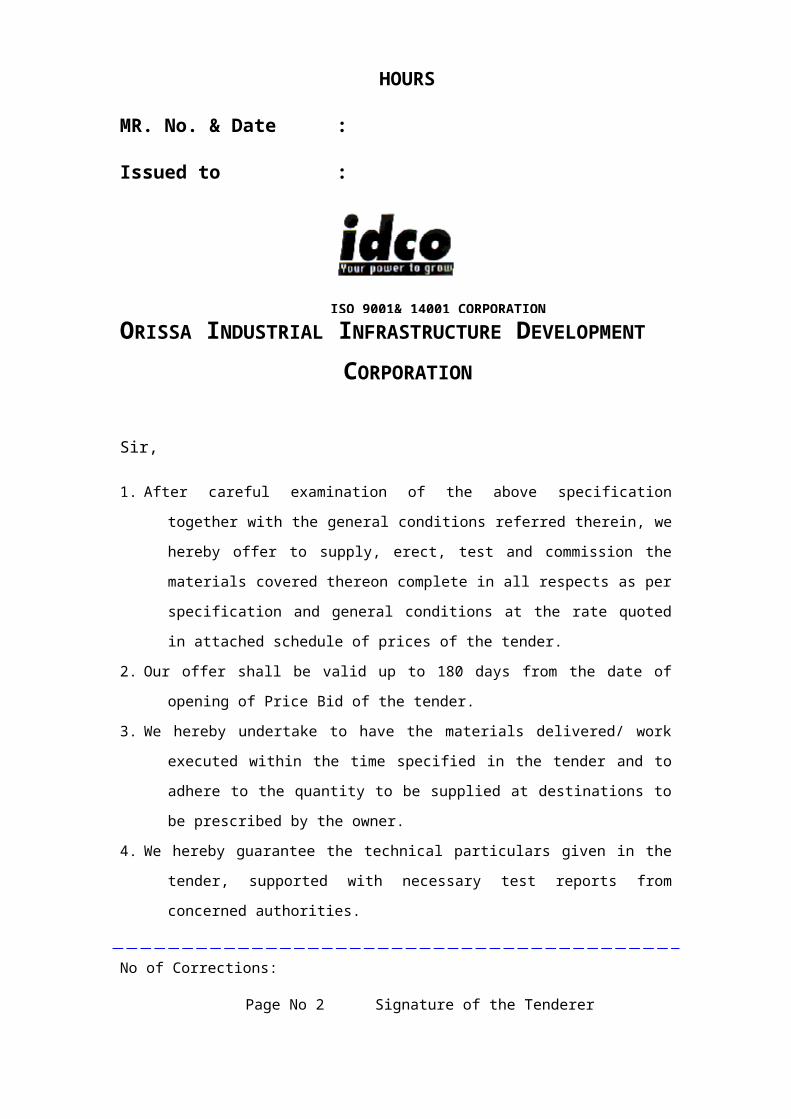
DETAILS OF SIMILAR CONCURRENT WORKSThe Bidder shall tabulate the details of similar works presently being undertaken by him or the manufacturer, on whose behalf he is
quoting, in the following proforma.
SSl No
Name of Client & Postal Address
Description of Work with capacity
Contract Value
Commence-ment Date
Scheduled Completion Time
Expected Date of Completion
Reasons for Time Over-run, if any.
No of Corrections:
Page No 17 Signature of the Tenderer

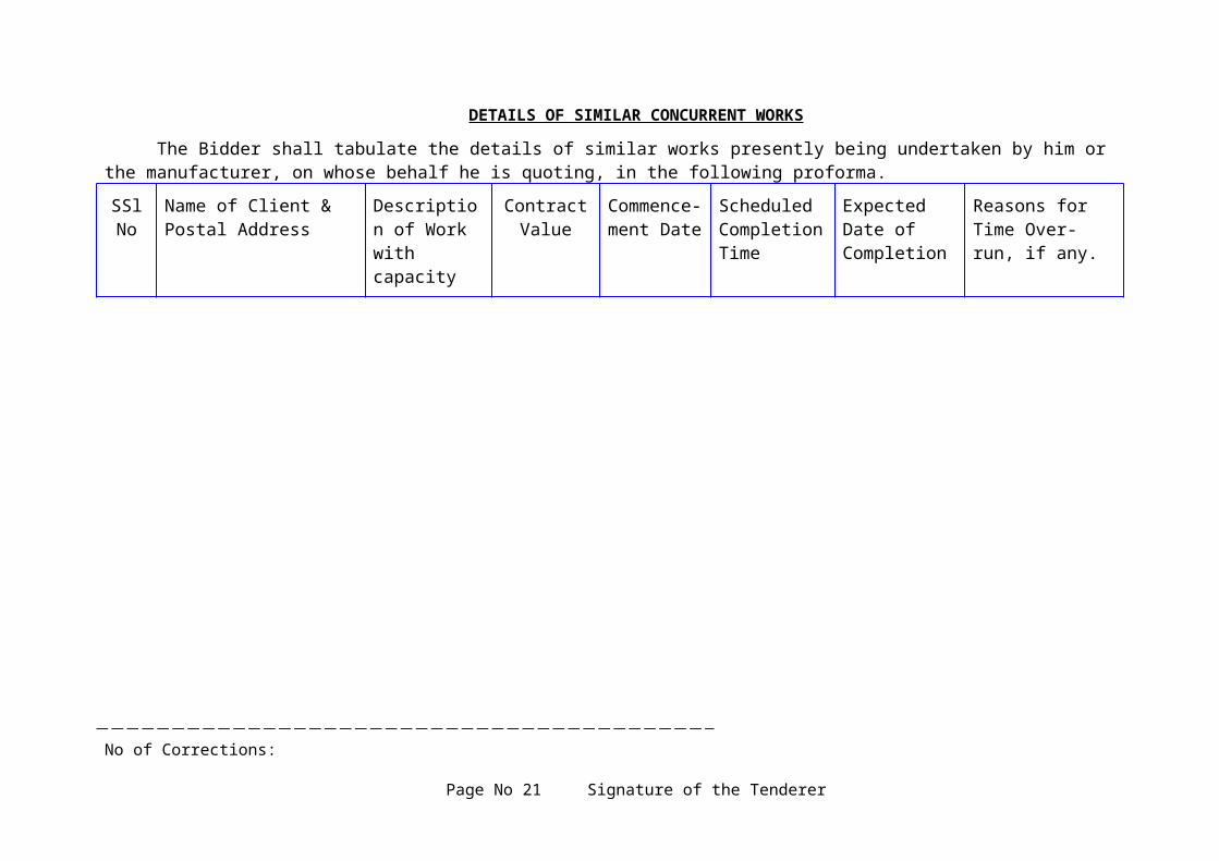
ANNUAL TURNOVER STATEMENT The bidders shall indicate herein his annual turnover during preceding 3 years based on the audited balance sheet/profit & loss account statement.
FINANCIAL YEAR ANNUAL TURNOVER (Rs.) NET WORTH (Rs.)
2003-2005
2004-2006
2005-2007
NOTE 1. Copies of audited balance sheets with profit & loss account statement for last 3 years are enclosed along the bid.
2. Bidders shall work out Net worth on following basis.
Net worth: Reserve + capital - accumulated loss
No of Corrections:
Page No 18 Signature of the Tenderer

INSTRUCTION FOR THE TENDERER
General Instructions:
The work put to tender pertains to Conversion of existing 33 KV OH
line (approx 10 kms) upgrading existing conductor to 100 sqmm AAA
conductor as well as construction of a new 4 pole structure with associated
works complete with supply, erection, testing, & commissioning”. The
tenderer shall ensure to follow the instructions given hereunder failing which
the tenders shall be liable for rejection.
Scope of Proposal:
The scope of proposal shall be in accordance with the enclosed
technical specification for Conversion of existing 33 KV OH line (approx 10
kms) upgrading existing conductor to 100 sqmm AAA conductor as well as
construction of a new 4 pole structure with associated works complete with
supply, erection, testing, & commissioning” on turnkey basis complete in all
respect.
Submission of Tender:
Tenderers are advised to fill up the prices in the prescribed format given by IDCO only. The tender shall be submitted in three parts, each part being sealed in separate envelope.Part I will cover the Commercial Bid such as the Letter of application, Commercial Terms and Conditions, VAT clearance certificate, Income tax clearance certificate, VAT registration certificate and EMD etc.Part ii will cover the technical bid with required drawings, general conditions, special conditions, technical specifications, guaranteed technical particulars and deviations, if any.Part iii will cover only the price bid.
Each envelope shall be duly sealed and super-scribed with
‘Commercial Bid’, ‘Technical Bid’ and ‘Price Bid’ respectively. All the
three envelopes shall be put inside another envelope, super-scribed with
No of Corrections:
Page No 19 Signature of the Tenderer

“Conversion of existing 33 KV OH line (approx 10 kms) upgrading existing
conductor to 100 sqmm AAA conductor as well as construction of a new 4
pole structure with associated works complete with supply, erection, testing,
& commissioning” Date of Opening: Dt.22.11.07” and sealed properly. The
Commercial bid and Technical Bid in Part (i) & (ii) shall be opened on the
due date of opening mentioned in tender call notice. Tenderers may be called
to participate in techno-commercial discussions/ negotiations for finalisation
of technical bid. The price bid shall be opened after finalisation of technical
bid.
Telegraphic tenders will not be accepted.
Receipt and Opening of Tender:Tenders as described above shall be received in the Office of the
Divisional Head (Elect), IDCO, IDCO Towers, Janpath Bhubaneswar and shall be opened on the scheduled date and time.Prices:
The tenderer shall ensure that all prices are filled in the price schedule
both in words and figures. No overwriting shall be allowed. The tenderer
shall countersign all scoring and cancellation. In case of illegibility, the
interpretation and decision of the Engineer-in-charge of the work shall be
final.
All entry shall be in English language only. The price should be
inclusive of all taxes, duties & transit insurance and FOR destination.
In case if on check, there are differences between the rate given by the
bidder in words and figures or in the amounts worked out by him, the
following procedure shall be followed.
No of Corrections:
Page No 20 Signature of the Tenderer
When there is difference between a rate in figure and in words, the rate that correspond to the amount worked out by the bidder shall be taken as correct.
When the bidder has not worked out the amount of an item or it does neither correspond with the rate written in figures nor in words, then rate quoted by the bidder in words shall be taken as correct.
When the rate quoted by the bidder in figures and in words tallies but the amount is not worked out correctly, the rates quoted by the bidder shall be taken as correct and not the amount.Sales Tax and Income Tax Clearance:
The tenderer shall furnish valid current VAT Clearance
Certificates, VAT Registration Number (TIN/ SRIN) and ITCC/ PAN along
with EMD contained in the envelope. Tenders not accompanied with these
documents shall be liable for rejection at the direction of the purchaser.
Please note that this office will not issue any concessional form for sales tax.
The purchaser shall not issue any Waybill.
Nature of Contract
The work put to tender as described “scope of proposal” being a job contract
in nature shall be treated as “Indivisible” works contract. Therefore this
contract shall be subject to “Orissa Sales Tax on works contract”.
Validity:
The Tenderers shall keep the tender valid for a period of 180 (one hundred eighty) days from the date of opening of price bid.Reservation of Right:
The owner reserves the right to accept any bid or reject any or all bids or cancel or withdraw invitation for bid without assigning any reason for such decision. Such decision, by the owner shall not be subject to question by any
No of Corrections:
Page No 21 Signature of the Tenderer
bidder and the owner shall bear no liability whatsoever consequent upon such a decision.Clarifications on Tender Specifications:
The tenderer should seek for the clarifications with regard to the specification, if any, before submission of the tenders. No correspondence on this account will be entertained after submission of tender. But the bidders may submit their manufacturers technical data alongwith the catalogue/literatures alongwith their tender.
No of Corrections:
Page No 22 Signature of the Tenderer

GENERAL TERMS AND CONDITIONS OF CONTRACT FOR
TURNKEY CONTRACT
Definition of Terms:
In construing this contract and the scope of work, the following words
will have same meaning herein assigned to them unless there is something in
the subject or context in consistent with such construction.
Owner:
The “Owner” shall mean the Orissa Industrial Infrastructure
Development Corporation (IDCO) (A Government of Orissa
Undertaking) and shall include its legal representatives, successors
and assignees.
Contractor:
The “Contractor” shall mean the firm whose tender has been
accepted by the owner and shall include its legal representatives,
successors and assignees.
Engineer In Charge:
The “Engineer-in-charge” shall mean the Divisional Head (Elect) , IDCO, Electrical Division, First Floor, IDCO Towers, Janpath, Bhubaneswar or his authorised representative.
Consulting Engineer:
The “Consulting Engineer” shall mean the General Manager (Electrical), IDCO, IDCO Towers, Janpath, Bhubaneswar or his authorised representative.
No of Corrections:
Page No 23 Signature of the Tenderer

Consignee:
The “Consignee” shall mean the person authorised by the Consulting Engineer / Engineer-in-charge to receive the materials, supervise and take measurement of the work.
Site:
The “Site” shall mean, the actual place of the proposed Project as detailed in the specification or other place where work has to be executed under this contract.
Specification:
The “Specification” shall mean collectively all terms stipulated in the contract known as General Conditions, Technical Specification and such amendments as may be made in the Agreement pertaining to method and manner of performing the work with respect of quantities & qualities of materials and workmanship to be furnished under the contract.
Contract:
The “Contract” shall mean and include the following documents:
(a) Invitation to Tender(b) Instructions to Tenderer(c) General Terms & Conditions of Contract(d)Technical Specification(e) Contract Agreement(f) Contractors’ tender proposal including clarification letters(g)Letter of Intend(h)Work order(i) Agreement
Commissioning:
The “Commissioning” shall mean the first authorised operation of the equipment / installation after completion of erection, testing, initial adjustments, statutory approvals etc.
No of Corrections:
Page No 24 Signature of the Tenderer

Approved:
The “Approved” shall mean the written approval of the Consulting Engineer / Engineer-in-charge.
Months:
Months shall mean the calendar month.
Performance Test:
The “Performance Test” shall mean all the tests as prescribed in the specification / ISS to be carried out by the contractor before taking over the installation by the owner.
Final Acceptance:
The “Final Acceptance” shall mean the owners written acceptance of the works performed under the contract after successful completion of Performance & Guarantee Test and Commissioning.
Contractor to Inform Himself Fully:
The contractor shall be deemed to have carefully examined the
General Conditions, Specifications, Schedules and Drawings and also to
have satisfied himself as to the nature and type of work to be executed and
where necessary of the site conditions and other relevant matters and details.
Any information thus had or otherwise obtained from the owner / consulting
engineer or the inspector shall not in any way relieve the contractor from his
responsibility for supplying the plant and equipment or material and
executing the work in terms of the specification including all details and
incidental works and supply of all accessories or apparatus which may not
have been specifically mentioned in the specification or drawings but
otherwise necessary for ensuring complete erection and safe and sufficient
working of the plant and equipment or installation.
No of Corrections:
Page No 25 Signature of the Tenderer

Deviation:
The contractor must get the sample materials, which are under scope
of supply of contractor, approved by OPTCL Authorities /Engineer-in-
charge before procurement otherwise the same shall be liable for rejection.
In case the tenderer wish to deviate in any way from the General
Conditions of contract or the Technical Specifications, he should draw
specific attention to such departure in his tender. All such deviations shall be
clearly mentioned in the Deviation Sheet giving the corresponding reference
clause Number. Terms such as See covering letter or Tender printed General
Terms & Condition are not acceptable, unless such deviations are submitted
with the tender, it will be understood and agreed that the Tenderers proposal
is based on strict conformance to purchasers specification in all respects.
Price:
i. The unit rates quoted for design, engineering manufacturing supply at site, storage, handling installation, testing and commissioning shall be inclusive of all taxes, duties, royalties and all other taxes applicable such as sales tax on work contract and income tax etc.
ii. The prices are to be quoted on the lump-sum price based on item rates as indicated in the specification. THE TENDERER SHALL QUOTE FIRM PRICES FOR THE COMPLETE SCOPE OF WORK. The prices are to be quoted for the work complete in all respects in strict accordance with the specifications. Should the Tenderer wish to propose alternatives the same should be clearly mentioned in the deviation. Any action on the part of the Tenderer to revise the price/ prices/ and/ or to change the structure of price/ prices at his own instance after opening of the tender may result in rejection of the tender.
No of Corrections:
Page No 26 Signature of the Tenderer

Terms of Payment:
Subject to any deduction which the owner may be authorised to make
under the contract, the contractor shall on the certificate of the engineer or
his authorised representatives whose certificate will be final regarding
evidence of materials at site and completion or erection etc. be entitles to
payments generally as follows.
Supply of Materials: 65% of the value materials shall be paid after receipt,
verification and acceptance of materials at site in good condition by CESU &/or Consignee / Engineer - in -charge and presentation of bills, subject to acceptance of your Security Deposit B.G. and execution of agreement.
25% shall be paid after completion of erection work. Balance 10% shall be paid on completion, satisfactory
commissioning, and performance tests and after necessary inspection by the statutory authority following final handing over to CESU, subject to your submission of performance B.G. and acceptance thereof.
Contract Price:
The lump sum price quoted by the contractor in his bid with additions
and deletion as may be agreed before signing of the contract for the entire
scope of the work viz. Supply and erection of equipment concerned under
the specification and documents shall be treated as the contract price.
Change of Quantity:
The owner reserves the right to vary the quantities of items or groups
of items to be ordered as specified in the accompanying Technical
Specifications as may be necessary during the execution of the contract.
No of Corrections:
Page No 27 Signature of the Tenderer

Taxes
The contractor shall include all taxes, duties, royalty of whatever nature, entry tax; other local taxes etc. if any in the quoted price.
Sales tax or any other tax on materials required for the work and also tax on works contract shall be payable by the contractor. Owner will not entertain any such claim whatsoever on this account.
Not with standing anything contained elsewhere in the contractor the owner shall deduct at source from the payment due to the contract, the taxes as required under VAT and Income Tax Act, 1961 or as amended from time to time, or any other statute. The owner shall pay the amount so deducted to the Sales Tax and Income Tax authorities as per the law. This is for the contractor to deal with the Sales tax Authority directly in respect to any claim or refund relating to the above tax owner shall not be liable or responsible for any type of payment for reimbursement in this regard.
The supplier / contractor should furnish his valid VAT with OVAT Registration Number.
Liquidated Damage for Delay in Completion:If the contractor fails in the due performance of the contract to supply/
erection/ testing / commissioning the equipment within the time fixed by the
owner or any extension thereof, he shall be liable at the discretion of the
Engineer to liquidated damage amounting to 0.5% (HALF PERCENT ) of the
contract price per week. The contractor’s liability for delay shall not in any
case exceed 5% ( FIVE PERCENT ) of the total contract price. If the contractor
shall fail to supply the equipment or any part thereof within a reasonable
period after the expiry of the appointed time of extended time as may be
provided for in the contract the provisions in clause " Negligence " shall
become operative, in addition to the liability of Liquidated Damage as
above.
No of Corrections:
Page No 28 Signature of the Tenderer

Despatch Instructions:
The materials that will be required to be despatched under this
contract, shall be despatched to the work site in the name of the Consignee
with a copy addressed to Divisional Head, Electrical Division, IDCO, First
Floor, IDCO Towers, Janpath, Bhubaneswar. The contractor shall have to
intimate the probable date of arrival of materials at site to the Engineer.
Inspection and Tests:
The corporation shall inspect, examine and test the equipment
material through its representative at the manufacture/ suppliers works
during or after the manufacture of goods prior to despatch on receipt of a
clear notice of minimum two weeks in advance to the reckoned from the
date of receipt by the purchase. The supplier/ contractor shall provide all
facilities as may be required to carry out the tests in accordance with
approved standards free of cost.
Negligence:
If the contractor neglects to execute the work with due diligence and
expedition of refuse or neglects to comply with any reasonable orders given
to him in writing by the Engineer in connection with the work, or contravene
the provisions of the contract, the purchaser may give notice in writing to the
contractor calling upon him to make good the failure, neglect or
contravention complained of. Should the contractor fail to comply with such
notice within a period, in the case of failure, neglect or contravention
capable of being made good within that time or otherwise within such time
as may in the opinion of the purchaser be reasonably necessary for making it
good, then and in such case the purchaser shall have the option and be at No of Corrections:
Page No 29 Signature of the Tenderer

liberty to take the work wholly or in part, out of the contractors hand and
may carry on the work envisaged in the contract at a price with any other
materials, tools, tackle or labour for the purpose of completing the works or
part thereof. In such event the purchaser shall without being responsible to
the contractor for fair wear and tear of the same be entitled to seize and take
possession and have free use of all materials, tools tackle or other things
which may be on the site, for use at any time in connection with the work to
the exclusion of any right of the contractor over the same and the purchaser
shall be entitled to apply and balance sum which may otherwise be then due
on the contract by him to the contractor or such part thereof as may be
necessary. If the cost of executing the work as aforesaid shall exceed the
balance due to the contractor fails to make good the deficit, the said
materials, tools tackle, construction plant or other things, the property of the
contractor as may not have been used up in the completion of the works,
may be sold by the purchaser and the proceeds applied towards the payment
of such sale. Any outstanding balance existing after crediting the proceeds of
such sale shall be paid by the contractor on the certificate of the Engineer,
but when all expenses, cost and charges incurred in the completion of the
work are paid by the contractor, all such materials, tools tackle,
construction plant or other things not used up in the completion of the works
and remaining unsold shall be removed by the contractors. If the proceeds of
the above sale of the contractors materials tools and tackle, construction
plant etc. are insufficient to cover the executing the aforesaid work, the
balance remaining after crediting the proceeds of such sale shall be
recoverable from the contractor by encasing the Bank Guarantee available/
any other money payable by the purchase or by action of law.
No of Corrections:
Page No 30 Signature of the Tenderer

Notwithstanding anything contained above, the purchaser may
determine the contract due to any breach of failure of the contract, without
notice before determining the contract as above, if in the opinion of the
purchaser, the default or defaults committed by the contractor is/ are curable
and can be cured by the contractor if an opportunity is given to him, then the
owner may issue a notice in writing calling upon the contractor or default
within such time as may be specified in the notice.
If the cost of executing the work as aforesaid shall exceed the balance
due to the contractor fails to make good the deficit, the said materials, tools,
tackle, construction plant or other things, the property of the contractor as
may not have been used up in the completion of the work, may be sold by
the purchaser and the proceeds applied towards the payment of such sale.
Any outstanding balance existing after crediting the proceeds of such sale
shall be paid by the contractor on the certificate of the Engineer, but when
all expenses, costs and charges incurred in the completion of the work are
paid by the contractor, all such materials, tools, tackle, construction plant or
other things not used up in the completion of the works and remaining
unsold shall be removed by the contractor. If the proceeds of the above sale
of the contractor's materials, tools, tackle, construction plant etc. are
insufficient to cover executing the aforesaid work, the balance remaining
after crediting the proceeds of such sale shall be recoverable from he
contractor by encasing the bank Guarantee available/ any other money
payable by purchaser or by action of law.
Notwithstanding anything contained above, the purchaser may
determine the contract due to any breach of failure of the contract, without
notice before determining the contract as above, if in the opinion of the
No of Corrections:
Page No 31 Signature of the Tenderer

purchaser, the default or defaults committed by the contractor is / are curable
and can be cured by the contractor if an opportunity is given to him, then the
owner may issue a notice in writing upon the contractor to cure the default
within such time as may be due in the event of termination, the security
deposit will be forfeited without reference to the contractor and if no amount
is available towards security deposit, an identical amount is recoverable
from the contractor.
Power to Vary or Omit Work:
No alternation, amendments, omissions, additions or variations of the
work herein after referred to as variations, under the contract shall be made
by the contract except as directed in writing by the Engineer, but the
engineer shall have full power, subject to the provision hereinafter contained
from time to time during the execution of the contract by notice in writing,
to instruct t the contractor shall carry out such variations and be bound by
the same conditions as far as applicable, as through the said clarifications
occurred in the contract, if any suggested variations would , in the opinion of
the contractor, if carried our, percent him from fulfilling any of his
obligations or guarantees under the contract, he shall notify the Engineer
thereof within 10 days in writing and the Engineer conforms his instructions,
the contractor’s obligations and guarantees shall be modified to such as
extent as may be justified. In the absence of any such notification, the
contractor shall be bound to carry out the suggested variations without any
additional financial implication to purchaser and it will amount to an
absolute waiver of any claim whatsoever.
No of Corrections:
Page No 32 Signature of the Tenderer

Settlement of Dispute:
Except as otherwise specifically provided in the contract all dispute
concerning questions of facts arising under the contract shall be decided by
the Engineer subject to a written appeal by the contractor to the Engineer,
whose decision shall be final to the parties hereto. Any dispute or difference
including those considered as such by only one of the parties arising out of
or in connection with the contract shall be to the extent possible settled
amicably between the parties.
Termination of Contract:
Notwithstanding anything contained elsewhere in this contract, if at
any time during the terms of this contract, the plans of the Government of
India and of the State Government change for any reason, the purchaser shall
have the right to terminate the contractor by notice to the contractor by a
registered letter. In respect of such changes the materials those are complete
as ready for transportation within thirty- (30)-days after such notice,
purchaser agrees to accept delivery thereof at the contract price and terms. In
the case of the reminder of the undelivered materials, the purchaser may
elect
To have any part thereof complete and take delivery thereof at the contract price and
To cancel the reside (if any) and pay to the contractor a prorate amount of the contract price based upon the state of completion to be certified by him.
The contractor shall deliver all such materials in process of
manufacture to the purchaser and shall return to the purchase any funds
remaining to the purchaser's credit. The purchaser shall not make any
No of Corrections:
Page No 33 Signature of the Tenderer

payment for any material not yet in process of manufacture on the date of
notice of cancellation is received.
Deductions from Contract Price:
All costs, damages or expenses which the purchaser may have paid,
for which under the contract the contractor is liable, may be deducted by the
purchaser from any money due or becoming due by him to the contractor
under the contract, or may be recovered by action of law or other wise from
the contract. Further all legal and statutory deductions will be made and the
contractor is not entitled to any reimbursement or claim whatsoever other
than only a tax deduction certificate.
In the event of recovery to the necessary extent becoming impossible owing to insufficiency of the performance bond and withheld amounts, the balance due to the purchase, may be recovered in any way the purchaser may deem fit.
Earnest Money:
The tenderer shall be required to submit earnest Money to be deposited as indicated in the NIT.The Bid Guarantee offered shall be in one of the following alternative forms:A crossed Bank Draft/ Banker’s cheque in favour of IDCO, Bhubaneswar payable at Bhubaneswar.An irrevocable Bank Guarantee of any Nationalised schedule Bank OPERABLE AT ITS BRANCH AT BHUBANESWAR ONLY in favour of IDCO, as per the proforma.The Bank Guarantee should be kept valid up to 12 (twelve) months from the date of opening of tender as per tender specification.Earnest Money shall be forfeited in case of withdrawal/ modification of an offer within the validity period as required in the NIT/ Tender specification after opening of tender. EMD shall be forfeited in case of non-acceptance of LOI / WO within stipulated period.In case of tenders not accepted, the earnest money shall be refunded within 30 days of the accord of order/ contract to the successful tenderer.
No of Corrections:
Page No 34 Signature of the Tenderer

Bids not accompanied by the required Bid Guarantee in accordance with the clause above, or if the Bid Guarantee is of in adequate value of the tender will not be entertained and shall be returned unopened.Bidders are to attend the techno-commercial discussion whenever called by the owner. In case the bidder fails to attend the techno-commercial discussion, the same will be treated as violation of tender condition and the EMD may be forfeited with rejection of the offer.
Security Deposit:
The successful Tenderers shall be required to submit security deposit for faithful execution of the contract at the rate of 10% (TEN PERCENT) OF THE CONTRACT VALUE in shape of Bank Guarantee from any Nationalised Bank operable at its branch at Bhubaneswar only VALID UP TO ONE MONTH AFTER THE COMPLETION OF CONTRACT PERIOD. In the event of default on the part of the contractor in the faithful execution of contract the security deposit shall be forfeited by an order of the purchaser. The forfeited of security deposit shall be without prejudice to any other rights arising or accruing to the purchaser under relevant provision of contract link L.D Negligence, termination etc.
Performance Bond:
The contractor shall furnish a performance bond as a guarantee for due performance during the guarantee period by way of a Bank Guarantee from any nationalised bank operable by its branch at Bhubaneswar to be kept valid for 12 months after completion of contract in all respects equal to an amount at a rate 10% ( TEN PERCENT ) of the total contract price for faithful filling the terms of guarantee for a period of 12 MONTHS AFTER SUCCESSFUL COMPLETION OF WORK. If during the contract period the bid amount gets reduced on account of any recoveries of otherwise the contractor shall furnish a bond covering the short fall to bring it to 10% of the contract value
Extension of Time:The application for extension of time is to be given to the owner
through the Engineer and the owner may authorise the extension of time
after considering the due merits. Whenever the owner grants extension of
time the same shall be on the existing terms and conditions of the contract
No of Corrections:
Page No 35 Signature of the Tenderer

and without financial liability to the owner. The contractor in any case shall
have no claim whatsoever for any of compensation on account of any delay
attributable to any one.
Erection of the Materials:
The contractor shall be responsible for complete installation of the equipment materials required under the scope of contract. The contractor shall provide all equipment, tools, scaffolding and minor civil works required for safe transportation and erection.
All the materials and/ or equipment after receipt at site shall be checked and verified against shipping documents and all claims against loss or damage in transit shall be intimated to the owner. All insurance charges such as transit insurance, storage insurance and handling insurance charges shall be borne by he contractor. The materials and / or equipments shall remain under the custody of the contractor until the owner takes up the plant / installation as a whole after completion of the work. The contractor shall take adequate steps to ensure safety of such materials and/ or equipment. Necessary stores receipt certificates shall be issued to the owner after the stores are checked and certified. No materials and/ or equipment pertaining to the contract shall be removed from site without the consent in writing of the owner. The contractor shall be responsible for obtaining the correct reference lines for purchases of fixing the alignment of various equipment and/ or materials.
Regulation of Local Authorities and Status:
The contractor shall comply with the rules and regulations of local authorities during the performance of his field activities. He shall also comply with the Minimum Wages Act, 1948 and the payment made there under in respect of any employee of workmen employed or engaged by his sub-contractor.The contractor shall get the entire installation inspected and cleared by the Electrical Inspector, Government of Orissa before commissioning. Only the statutory inspection and drawing approval fees, if any, in respect of his work pursuant to this contract shall be reimbursed to the contractor on production of documentary evidence. However, any registration, statutory inspection fees lay fully payable under the provision of any other Regulations and statutory laws or amendments thereof from time to time shall be to the account of the contractor.
No of Corrections:
Page No 36 Signature of the Tenderer

Should any such inspection or registration need to be rearranged due to the fault of the contractor or his sub-contractor, the additional fees for such inspection and/ or registration shall be borne by the contractor.
Manufacture's Supervision:
The contractor may be required to work under the supervision of the manufacture's Engineer, where the contractor is not the manufacture. However, this will not relieve the contractor of his responsibility of the correctness of quality of workmanship shall be responsible for the correctness of the positions, levels and dimensions of the works according to the drawing, notwithstanding that he may have been assisted by the Engineer in setting out the same.
Taking Over:
Upon successful completion of all the tests to be performed at site on equipment and/ or materials and systems supplied and erected by the contractor the Engineer shall issue to the contractor a taking over certificate as a proof of the final acceptance of the equipment system. Such certificate shall not relieve the contract of any of his obligation which otherwise survive by terms and condition of the contract issuance of such certificate.
Engineer's Decision:
In respect of all materials, which are left to the decision of the Engineer, the Engineer shall if so required to do so by the contractor given in writing a decision thereon to the contract. All decisions of the Engineer shall be binding on the contractor.
Completion Certificate & Final Certificate:
When the contractor fulfils his obligation under the contract he shall be eligible to apply for completion certificate in respect of the work by submitting the completion documents along with such application for completion certificate.
The owner of his representative shall normally issue to the contractor the completion certificate within one month after receiving an application there of from the contractor after verifying from the completion documents and satisfying that thework has been completed in accordance with and as set out in the construction and erection drawings, and the contract documents. The contractor, after obtaining the completion certificate is eligible to present the final bill for the work executed by him under terms of the contract.
No of Corrections:
Page No 37 Signature of the Tenderer

Completion Certificate:
Within one month of the completion of work in all respects, the contractor shall be furnished with a certificate by the owner or his representative of such completion but no completion certificate shall be given nor shall the work by deemed to have been executed until all scaffolding, surplus materials and rubbish are cleared off the site completely nor until the work shall have been measured by the Engineer, whose measurement shall be binding and conclusive, the binding and conclusive, the work will not be considered as complete and taken over by the owner until the temporary works and staff colonies etc. constructed are removed and work site cleared to the satisfaction of the owner.
If the contractor shall fail to comply with the requirement of this
clause on or before the date fixed for the completion of the work, the
Engineer may at the expense of the contract remove such scaffolding,
surplus materials and rubbish and dispose off the same as the things fit and
clean off such dirt as aforesaid, and the contractor shall forth will pay the
amount of all expenses so incurred and shall have no claim in respect of any
such scaffolding or surplus materials as aforesaid except for any sum
actually realized by the sale thereof.
Completion certificate shall be in 3 parts as follows:(a) Physical/ Mechanical completion work.(b)Satisfactory completion of commissioning of equipment with load.(c) Satisfactory completion of guarantee.
The contractor shall clearly indicate the three dates separately for
completion documents / to form the completion documents.
The technical documents according to which the work was carried out.Three sets of construction drawings showing therein the modification
corrections made during the course of executing and signed by the Engineer.
Completion certificate for embedded and Covered-up works.Certificates of final levels as set out for various works.Certificates of tests performed for various works.
No of Corrections:
Page No 38 Signature of the Tenderer
Materials appropriation statement for the materials issued by the owner for the works and list of surplus materials returned to the owner’s store duly supported necessary documents.
Physical/Mechanical completion work.Satisfactory completion of commissioning of equipment with load.Satisfactory completion of guarantee.Miscellaneous:Entire Agreement:
These General Conditions together with the specifications, tender
drawing and guaranteed technical particulars, tender data with subsequent
agreed modification thereof shall constitute the entire Agreement between
the parties in respect of the subject matter thereof. No variation of
modification of the contract of modification of the contract of waiver of any
of the terms and conditions thereof shall be deemed valid unless in writing
and signed by the parties hereto.
General Conditions of Contract, the tender specification and other
contract/tender documents are to be taken as mutually explanatory to one
another. However, in case of conflict between these documents, the technical
specification, special conditions of the contract and general condition of the
contract shall have precedence in that order.
Endorsement of Terms:
The failure of either party to endorse at any time of the provisions of
the contract of any rights in respect there to or to exercise an option herein
provided shall in no way be construed to be a waiver of such provisions,
rights of options or in any way to effect the validity of the contractor. The
exercise by either party of any of his herein shall not preclude of prejudice
either party from exercising the same of any other it may have hereunder.
No of Corrections:
Page No 39 Signature of the Tenderer

Contract Labour Regulation & Abolition:
The contractor shall be responsible for following all statutory obligations
under Contract Labour (Regulation & Abolition) Act, 1970, E.S.I and
Provident Funds Acts as applicable for their labour and staff engaged in
executing this work. The contractor will also keep purchaser indemnified
against all claims and disputes arising out of death or injury to their
workmen and staff. It will be necessary for the contractor to ensure that their
workmen follow proper safety measures to avoid accident/ damage/ loss to
life and property. Their workmen when working at any height must use
approved safety belts. Charges for above are deemed included in the quoted
rates and accepted amount. The bidder shall furnish the photocopy of their
valid registration with Provident Fund Department.
Recovery of Damage:
Nothing contained in the conditions or in any other part of this
contract, in case of any damage, it shall be construed as the purchaser
preventing the contractor from committing the damage and the purchaser
shall be entitled to recover the amount required for the repair/ replacement/
rectification of the damage as a consequence of the breach of any of the
terms of the contract by the contractor.
Completeness of Equipment / Installation:
The equipment / installation shall be complete in every respect with
all mountings fixtures and standard accessories which are normally even
though not specifically detailed in the specification.
The contractor shall be eligible for any extra payment in respect of
such mounting, fittings and fixtures and accessories which are needed for
No of Corrections:
Page No 40 Signature of the Tenderer

safe operation of the equipment/installations as required by applicable codes
though they may not have been included in the contract. The various
equipment and / or materials supplied this contract shall be subject to the
purchaser/owners approval.
Time Schedule:
Time is the essence of the contract and the contractor shall be responsible for performance his works in accordance with the specified construction schedule. The offer should clearly indicate monthly/ quarterly schedule of deliveries, date of commencement and completion of supply erection testing and commissioning against that indicated in the NIT/construction schedule. If any time the contractor failing behind schedule he shall take necessary action to make good for such delays by increasing his work to comply with the schedule and shall communicate such actions in writing to the Engineer satisfying that the action will compensate delay. The contractor shall however not be responsible for provision of additional labour and / or materials or supply of any other services to the contractor except for the co-ordination of works. The entire scope of work shall be completed within 2 (TWO) MONTHS from the date of issue of work order.
Safety Regulations:
Without prejudice to the general obligations under the statutes the contractor shall ensure the safety of all the workmen, materials and equipment either belonging to him or to others working at site.
Subletting of Contract:
The contractor shall not without the consent in writing of the purchaser, which shall not be unreasonably withhold, assign or sublet his contract of any substantial part thereof other than for raw materials, for minor details, or for any part of the works of which the markers are named in the contract, provided that any such consent shall not relieve the contractor from any obligation, duty or responsibility under the contract.For components/equipment procured for the purpose of the contract, after obtaining the written approval of the owner, the contractor’s purchase specifications and inquiries shall call for quality plans to be submitted by the suppliers along with their proposals. The quality plans called for from the No of Corrections:
Page No 41 Signature of the Tenderer

vendors shall set out during the various stages of manufacture and installations, the quality practices and procedures followed by the vendor’s quality control organisation, the relevant reference documents/standards used, acceptance level, inspection of documentation raised, etc. Such quality plans of the successful vendors shall be discussed and finalised in consultation with the Engineers and shall from a part of the purchase order/ contract between the contractor and the vendor. Within 3 weeks of the release of the same purchase order /contracts for such bought out items/ components a copy of the same without price details but together with detailed purchase specifications, quality and delivery conditions shall be furnished to the Engineer by the contractor.
Force Majeure:
Any delays in or failure of the performance of either parties thereof shall not constitute default here or give rise to any claims for damages, if any, to the extent such delays or failure of performance caused by occurrences such as acts of God or the public enemy, expropriation or confiscation of facilities by Government authority, compliance with any order or request of any Government authorities, act of war, rebellion, sabotage, fire, floods explosions, riots or illegal strikes, provided always that such occurrences result in impossibility or performances of the contract. Only events of force majeure, which impedes the execution of the contract at the time of its occurrence, shall be taken into cognisance.
Language and Measurement System:
All documents pertaining to the contract including specifications schedules, notices, correspondence operating and maintenance instructions drawings or any other writing shall be in English Language. All measurements, location marking and drawings shall be in Metric Units.
Materials and Workmanship:
All materials used in the manufacture of these equipments shall be selected from the best available for the purpose, considering strength, durability and best engineering practice. Liberal factors of safety shall be used through out the design and especially in the design of all parts subject to alternation stresses or shocks. All the work shall be performed and completed in a thorough workmanship like manner and shall follow the best modern practice in the manufacture of high-grade equipment notwithstanding any No of Corrections:
Page No 42 Signature of the Tenderer

omissions in the specification. Castings shall be free blow holes, flaws, cracks of other defects and shall be smooth, close grained and of true forms and dimensions. No plugged or filled up holes or other defects will ordinarily be allowed. Such castings are liable to be rejected.However, the contractor may rectify minor casting defects be welding or other method in accordance with the standard manufacturing practice provided such rectification does not affect the strength of the casting or impair the efficient working of the plant and proper approval of the purchaser is obtained for the same.
Facility to the Contractor:
The purchase/ owner will at his own discretion and convenience and for the duration of the execution of the work make available near the site land for construction of contractors field office, go-downs, workshop and assembly year required for the execution of the contract. The contractor shall at his own cost construct all these temporary buildings and provide suitable water/ electricity and sanitary arrangement after obtaining approval from the Engineer. On completion of the works undertaken by the contractor he shall remove all temporary works erected by him and have the site cleared as directed by the Engineer. If the contractor fails to comply with these requirements, the Engineer at the expense of the contractor will remove such surplus and rubbish materials and dispose off the same as he deems fit and get the site cleared as aforesaid and the contractor shall forthwith pay the amount of all expense so incurred and shall have no claim in respect of any such surplus materials disposed of as aforesaid. But the purchaser/ owner reserves the right to ask the contractor at any time during the pendency of the contract to caveat the land by giving 7 days notice on security reasons or national interest or otherwise a token rent of Rs. 100/- per month per hectare a part thereof shall be charged for the land so occupied. Electricity and drinking water at normal charges will be supplied at one point. The cost of distribution if any shall be borne by the contractor.
Modification Prior to the Date of Tender Opening:
The purchase/ owner reserves the right revise or amend the tender specifications prior to the date notified for opening of the tender and also the right to postpone the date for presentation and opening of tender without assigning any reason, whatsoever.
No of Corrections:
Page No 43 Signature of the Tenderer
Clarification Desired by the Tenderer:
The tenderer, before submission of the tender, should seek for any clarification with regard to the specifications. No correspondence on this account will be entertained once the tenderer has submitted the tender.The contractor will be responsible for any loss theft, destruction and deterioration of quality of any materials when it is in the storage under the custody of the contractor. A custodian certificate is to be issued by the firm to the owner. The purchaser reserves the right to inspect the materials under the custody of the contractor from time to time. The contractor will indemnify the owner for any loss arising due to any reason whatsoever of the materials during storage under the custody of the contractor.The contractor will make good of the loss at his own cost and arrangement without waiting for settlement of claim from insurance of any other Agencies.
Consignee:Divisional Head, Electrical Division, IDCO, First Floor, IDCO
Towers, Janpath, Bhubaneswar shall be the Consignee.Inspection & Handing over
It is the responsibilities of the Contractor to get the installation inspected & obtain clearance from EI, Govt of Orissa following the handing over of the completed installation to CESU.. It is also the responsibility of the Contractor to get power shut down from OPTCL/CESU authority as & when required for the installation work.Jurisdiction of Court:Dispute / Litigation if any, arising out of this contract deemed to have been entered into at Bhubaneswar shall be under the jurisdiction of Orissa High Court.
T E C H N I C A L S P E C I F I C A T I O NThe installations shall generally be carried out in conformity with the
requirements of Indian Electricity Act, 1910 as amended up to date and Indian Electricity Rules, 1956 framed there under, the relevant regulations of the Electric Supply Authority concerned. The work shall be executed as per
No of Corrections:
Page No 44 Signature of the Tenderer

National Electrical Code and if any item is not covered there under or there is any doubt, the specification approved by the Engineer-in-charge will be final and binding.
Ambient Conditions:
All Electrical installations and equipments shall be suitable to work in following ambient conditions.
Maximum Temperature : 50-Degree Celsius
Relative Humidity : 100%
In the vicinity : Cuttack district System Conditions:
The Electrical installations and equipments shall be suitable for operation in following system conditions.
Supply voltage : 33000 Volts, +/-10%
Supply frequency : 50 Hz, +/-5%
Number of Phases : Three
Scope of Work:
The scope of this work covers supply of all materials and labour required for the construction of 33 KV overhead lines/under ground cabling in the exact location as specified in the bill of quantities complete including statutory Electrical inspection etc., as required. The Corporation shall reimburse the statutory fees deposited in Govt. treasury. Any item that has not been specifically mentioned in the tender schedule but required for satisfactory commissioning shall be borne by the contractor. No extra payment is to be made on this account
No of Corrections:
Page No 45 Signature of the Tenderer

Salient features:-1.Type of 33 KV line Three phase Three wire 33 KV over head
line2.Support for 33 KV Line 11.00 mtr. Long 150x150 mm R.S.Joist3.Span length 80 Mtr. Approximately4.Conductor 100-sqmm AAA conductor
All materials, fittings, appliances used in electrical installations shall confirm to Indian Standard Specifications wherever these exist. All required materials covered under this specification should be supplied and installed by the contractor complete in all respect. The materials and accessories those are required for completing the work would form part of the work although they have not been specified separately.
Selection of materials and installation work shall be such as to simplify operation, inspection, maintenance and testing. The work shall include all reasonable precautions and provisions for safety of operation and maintenance personnel.
Standard:-
(a) Unless otherwise specified, all materials covered under this specification shall be designed, manufactured, tested and installed in conformity with the latest Indian Standard Specifications. In case such Indian Standard Specifications are not published equivalent British Standard Specifications shall be followed. All equipments and installations shall confirm to latest Indian Electricity Rules, REC standard, CESU norms, PWD and Local / State laws or byelaws as regards to safety, earthing and other essential provisions specified therein. Lines and sub-stations must be constructed as per latest Indian Electricity Rules, REC standard, CESU norms, which are subject to inspection by CESU Authorities and Electrical Inspector of the State Government.
(b) All equipments and materials selected shall also be supplied and installed taking into consideration the Factories Act, Fire Regulations and Local laws or bylaws.
No of Corrections:
Page No 46 Signature of the Tenderer

(c) All the materials supplied by the contractor according to the contract conditions will be subject to inspection, approval and acceptance by the Engineer-in-charge / CESU authorities or their authorized representative from time to time. The contractor shall extend all required facilities for such inspection free of cost. At the time of inspection, the inspecting officer shall have full liberty to reject any such material, which does not confirm to specifications or the requirements. The owner shall not entertain any claim for any rejected materials. The contractor shall remove all rejected materials from the site at his own cost.
(d) The owner shall not accept any surplus material procured by the contractor.
(e) The contractor will be responsible to get electrical installations inspected by the Electrical Inspector of the State Government/ Central Government and to obtain the statutory clearance for energisation. Only the statutory fees deposited by the Contractor in the Govt. treasury shall be reimbursed on production of documentary evidence.
(f) The contractor will be responsible for handing over of the installations to CESU authorities. The cost of watch and ward of the installations till final handing over to CESU shall be borne by the contractor.
(g) The contractor should possess valid electrical contract license, RPF registration and labour license issued by the appropriate statutory authority of the State/ Central Government during the execution of the contract.
Inspection and Approval of materials .
The pre-delivery factory inspection (PDI) shall be conducted for major materials such as RS Joist poles, Conductor, etc., as mentioned in respective technical specification. The authorised engineer of IDCO shall witness the PDI. Minimum 7 days clear notice in advance shall be given to depute the inspecting officer. The materials shall be despatched to the site after issue of despatch clearance by Engineer-in-Charge / Divisional Head (Elect).
No of Corrections:
Page No 47 Signature of the Tenderer

The contractor shall put up samples of other items for approval by the Engineer-in-charge. The contractor shall furnish the original bills of the procured materials to the concerned E-I-C/CESU authorities for verification, if required.
SPECIFICATION OF 3-PHASE 3 WIRE OH LINE
JOIST Pole :-
Supply: - 11 mtr long 150x150mm R.S.Joist Pole confirming to IS shall be supplied by contractor. The pole should be of approved make and shall be despatch after conducting pre delivery factory inspection and issue of despatch clearance by this office.
Pole erection:-
The average spacing of the poles shall be 70-80 mtrs. However, the exact location of pole supports shall be finalized as per site conditions in consultation with the engineer-in-charge. Pole pits of depth 1/6 th of the pole height shall be excavated in all kinds of soil and rock. 1:3:6 PCC base padding of thickness 150-mm shall be provided at the bottom of the pole pit & balance of the pit should be provided with mass concreting in 1:4:8 P.C.C No of Corrections:
Page No 48 Signature of the Tenderer

ratio using 40-mm HG metal. Care should be taken for perfect leveling of the pole to keep it straight & after erection it should be provided with couping of size mentioned in the BOQ with plastering complete. Each pole should be coil earthed as per specification & standard & Anti-climbing device and Danger notice boards shall be fixed on the poles as per I.E. Rules / REC Specification. Nomenclature of the poles shall be made with enamel paint.
A pole shall be erected as a strut when support to the pole by a stay is not possible .The strut pole shall be of the same specification as the normal poles. The strut poles shall be erected at an angle of 45 deg. approximately with the horizontal. All other erection procedures shall be same as stated above for pole erection.
Stay Set:
HT stay sets shall be installed at all end points, tapping points, DP structure and cut points of the overhead line as required as per direction of Engineer-in-charge.
Supply:
The HT stay set suitable for 33 KV line as per standard comprising of stay rod, turn buckle, thimble, anchor plate, HT guy insulator and stay wire (7/8) shall be supplied by the contractor.
No of Corrections:
Page No 49 Signature of the Tenderer

TECHENICAL SPECIFICATION FOR HT STAY SET.
1. MS stay rod of 20-mm diameter 1800mm in length, one side formed an eye and welded with internal diameter 40mm with one thimble and the other side of the rod is threaded and fitted with 2 nos. Suitable hexagonal nuts with one round washer of 3 mm thickness complete with ms anchor plate 250x250x6mm dimension with centre hole of 22mm diameter. The entire rod, plate, thimble, nuts and washer should be hot dipped galvanized as per is: 2633-1972 (as per OSEB drawing no-9634/92).
2. Single bow turnbuckle made of 16mm diameter MS rod and the centre rod of 20mm diameter of length 450mm with one end formed an eye and welded. The threaded length of the centre rod should be 300mm. The base channel of the bow of size 75x40x6mm and 180mm in length with thimble and 2 nos. suitable hexagonal nuts. The items should be hot dipped galvanized as per IS-2633/1972 ( As per drawing No-9675/92)
Stay installation:-
Stay pit of size (0.9-m x 0.6-m x 1.4-m depth) shall be excavated in all kinds of soil and rock. The stay rod with anchor plate shall be installed therein and the pit shall be filled in with 1:3:6 PCC using 40-mm HG metal. Proper curing of PCC shall be done to enable the concrete to acquire strength. The binding of stay shall be done before the stringing of conductors neatly by twisting each and every stand of stay wire. The stay insulator shall be provided at least at a height of 3.0-metre from the ground level and fixed in such a fashion that the wires would not fall on ground in case of the failure of the insulator.
Cross arms: -
Supply: -
The cross arms required for the work shall be supplied by the Contractor at his cost. The following types of cross arms shall normally be
No of Corrections:
Page No 50 Signature of the Tenderer

used in the construction of 11KV overhead line.
Straight cross arm
V cross arm
Pole top channel
The Straight cross arms shall be used in pairs and fabricated out of 1500-mm long ISMC-100 (100 x 50 x 6-mm mild steel channels). The V cross arms shall be fabricated from ISMC-100 (100 x 50 x 6-mm ISMC) as per REC specifications, CESU norms and I.E. Rules. The pole top channel shall be fabricated from ISMC-100 of required length as per standard.
Cross arm installation:-
The straight cross arms shall be used in pairs. Two numbers pressure bolts shall be provided for maintaining the uniform gap between the cross arms. The V cross arms shall be fixed using suitable clamps. The pole top clamps shall be either directly bolted in the nuts provided in the pole or fixed using suitable clamps. The cross arms shall be properly fixed on the pole with nut and bolt after de-rusting. These shall be painted with two coats of red oxide primer and finished with two coats aluminium painting. Earthing lead connection shall be made to the cross arms by 6 swg GI wire from pole top earthing point. All the nut bolts should be of GI only.
Insulators:-
Supply: -
The 33 KV insulators and associates hardware shall include the following
33 KV pin insulator with GI pin
33 KV string insulator with hardware fitting (B&S type)
All other materials required for installation of insulators such as GI nut bolts etc shall be provided by the contractor.
No of Corrections:
Page No 51 Signature of the Tenderer
Installation of Insulators:-
The 33 KV insulators shall be fixed to the cross arms using suitable hardware only as per REC specification, CESU norms and I.E. Rules complete & as per direction of Engineer-in-charge.
Conductor- :-
Supply: -
100-sqmm AAA conductors shall be supplied by the contractor confirming to the following technical specification. The conductors shall be dispatched to work site after conducting the pre-delivery factory inspection and issue of despatch clearance by this office.
TECHNICAL DETAILS OF 100-sqmm AAAC AS PER IS: 398
Sl No Description Acceptance Criteria
Indian Standard No IS-398 (Pt4) 1994
Number and diameter of wires 7/4.26 No/mm
Total area of conductor 100-sqmm
Overall diameter of stranded conductor 12.78 mm
Mass of Conductor per Kilo-meter 272.90 Kg.
Breaking load 2843.5 Kg
Max. Length of conductor supplied on one drum
6 Km
Calculated maximum resistance at 20 deg. C.
0.3299 Ohm/Km
Current carrying capacity 260 Amp at 75*
No of Corrections:
Page No 52 Signature of the Tenderer

Installation of Conductor (Stringing): -
The conductor stringing shall be carried out including scaffolding as per standard practice of CESU maintaining proper sag and tension. Paving of 100-sqmm AAA conductors shall be done carefully such that no sharp twist and no scratch should be developed in the conductor. All required bindings and jumpering etc shall be done using Aluminium binding wire and PG clamps only. Proper clearances as specified in IE Rules shall be maintained.
Earthing:-
The earthing installations shall generally conform to IS: 3043/1966 and requirements of Indian Electricity Rules, 1956. GI coil earthing of specific length & turns shall be provided for earthing of every support of the line. Pipe earthlings shall be provided for earthing of every cut point poles and line DP structures as required. Earthing lead using 6 SWG GI wires shall be laid and firmly connected to the grounding points provided in the poles. All materials required for earthing such as coil earth electrode / GI pipe earth electrode, salt, charcoal etc shall be supplied by the Contractor.
Earthing leads:
GI flats / wire of appropriate size as specified in bill of quantities shall be laid as earthing lead. For earthing of cross arms No-6 GI wire shall be used as earthing lead..
Danger Notice Board:
All the overhead line supports and distribution equipments shall be fitted with danger notice boards mentioning the system voltage confirming to IS: 2551/1963. The danger notice boards shall be fitted at a height of 3000mm above the ground level in case of overhead line supports. It shall be made of a 1.6mm thick mild steel sheet duly derusted, primered, vitreous enamelled with white letters and marked with conventional skull and bone signal in red colour. The "Danger" & its appropriate translated word along with the system voltage shall be written in Oriya, English and Hindi languages. The sizes recommended are as follows
No of Corrections:
Page No 53 Signature of the Tenderer

For low & medium voltages up to 650 Volts : 200mm x 150mm
For high voltages above 650 Volts : 250mm x 200mmTECHNICAL SPECIFICATION FOR 250 KVA 33KV/0.433 KV STATION TRANSFORMER
1. TYPE:
The Transformers shall be of the out door core type double wound oil immersed self cooled type ‘ON’ and conform to ISS 1183/1964 and 2026/1977 with up-to-date amendments.
All the transformers shall be suitable for operation in humid atmosphere in the tropical place with ambient temperature ranging from 50˚ to 60˚ C.
2. STANDARD
The transformers shall comply with ISS 2026/1977 and 1183/1964 or the latest version thereon with Class-A materials specified therein and should be designed taking ambient temp. as 50˚ C.
3. RATING
The transformer shall have core type Alluminium wound construction, oil immersed ‘ON’ suitable for out-door service as a step down transformer. The rating and electrical characteristics of the transformers shall be as follows:
Frequency - 50 Hz ± 5%Continuous rating - 250 KVARated HT/LT voltage - 33/0.433 KVNumber of phase - 3 phasesConnection HT - DeltaConnection LT - StarVector group - Dyn – IITaps - -5% to +7.5% in steps 2.5%
in high voltage side.
ix) Percentage impedance at -+5% (Minimumcontinuous maximum (No negative tolerance is
allowed)rating at 75˚ C
No of Corrections:
Page No 54 Signature of the Tenderer

x) Type tap changer for transformer(Rotary type, off load control
tap changing gear)xi) BIL - 170 KVPxii) terminal connection -Bimetallic clamp suitable for
AAA conductor as per system
Requirement.xiii) Minimum knee point voltage 110% rated voltage
(This will be verified during no load loss test in the method that by increasing voltage by 10% of the 1105 rated voltage, the existing current shall not increase by more than 50%).
4. The primary-winding shall be connected Delta and secondary winding star as per vector symbol Dyn-11(IS:2026/1977). The terminal arrangement shall be out door bushing suitable for bare 100 sqmm AAA conductors for 33 KV side and with LT end terminal box with extended copper terminal to suit 2 no of 3 ½ x185 mm² AL armored PVC cable in LT side.
The temperature rise should not exceed the limits stated in relevant standards. The transformer shall be capable of withstanding thermal and mechanical effects, of a short circuit on the terminals of any winding with full voltage maintained on other windings for a duration of at least five seconds.
5. INSULATION
5.1 The electric strength of the winding insulation and of bushings shall conform to the values given in the IS:2026/1977.For rated system voltage of 33 kV the impulse test voltage is 170 kV (Peak).All windings of the transformer shall have uniform insulations.
6. VOLTAGE RATIO
No of Corrections:
Page No 55 Signature of the Tenderer

The transformers shall be for the rated kV specified on the HV side and on the LV side.
The insulation and magnetic circuit shall be suitable for working continuously at 10% in excess of the normal voltage and at the same time at a frequency of 3% below the normal.
7. CURRENT DENSITY
The current density in windings shall be kept within 2.4 A/sq.mm.
8. FLUX DENSITY
The maximum induction with maximum system i.e. 36 kV frequency and the type of steel used for core laminations should be stated in the tender. Flux density at maximum system voltage i.e. 36 kV and lowest frequency 48.5 C/S should not exceed 1.6 Tesla.
9. FREQUENCY
The transformers shall be suitable for continuous operation with a frequency variation of plus or minus 3% from the normal frequency of 50 Hz without exceeding the temperature rise specified in clause – 15.
10. TERMINAL ARRANGEMENTS
HT side – Bimetallic clamp type, suitable for 10 sqmm AAA conductor as per requirement and layout.
LT side – cable connection, 2 no of 3 ½ x 185 mm² armoured PVC aluminium cable. The neutral side of the standing brought to a separate insulation terminal for earthing purpose.
11. TAPPINGS
Tappings range shall be 12.5% in steps of 21/1% and it shall be off road type with local control. The taps shall provide for voltage adjustment on the high voltage side from –5% to +7.5% of the rated voltage, the tappings being located on higher voltage winding.
No of Corrections:
Page No 56 Signature of the Tenderer

The transformer shall be so designed that the temperature rise is maintained within limits, specified in relevant standards when operated at full output or constant primary service voltage on any primary tappings irrespective of the tapping corresponding to the service voltage.
An externally operated off circuit tapping switch shall be provided to enable changing of taps without removing the transformers cover or lowering of the oil level. The transformer shall give full rated KVA output of each winding at all the taps.
The switch mechanism shall be so designed as to prevent the entry of moisture into the tank. The design of the switch mechanism shall ensure that the switches are making full contact and then only it shall be possible to look the operating mechanism. The tap mechanism shall be provided with a locking device.
12. BUSHING TERMINALS
All main winding and neutral leads shall be brought out through outdoor type bushing suitable for bare copper or ACSR conductors for 33 kV side and to 3 ½ x 300 mm² armoured PVC cable so located that the full flash over strength will be utilized.
Each bushing shall be so co-ordinated with the transformer insulation that all flash overs will occur outside the tank. The porcelain used for the bushings shall be of the wet processed type, homogenous and free from cavities or other defects. The glaze of the porcelain parts shall be uniform in colour and free of blisters burns and other defects.
The bushings should conform to IS: 2099/73 and with 3347(Part-I & II Section – 1 & 2).
13. FLASHOVER CHARACTERISTICS OF BUSHINGS
The spacing between the bushings must be adequate to prevent flash over between phases under all condition of operation. Special adjustable coordinating gaps should be provided on the high-tension terminals and the gap setting adjusted with reference to the impulse coordination of the system. The tenderer is requested to give the guaranteed with stand voltage for the impulse and flash over values of the bushings.
No of Corrections:
Page No 57 Signature of the Tenderer

14. SUPPRESSION OF HARMONNICS
The transformers shall be designed with particular attention to suppression of harmonic voltages especially the 3rd and 5th
so as to eliminate wave form distortion and any possibility of high frequency distortion and any possibility of high frequency disturbances, inductive factor or of circulating current between neutral point at the different transformer station reaching such a magnitude as to cause, interference with post office or other communication circuits.
15. CENTRE OF GRAVITY
The center of gravity of the assembled transformer shall be low and as near the vertical center line as possible. The transformer shall be stable with or without oil. If the center of gravity is eccentric to the vertical line either with or without oil, its location shall be shown on the outline drawing.
16. VIBRATION AND NOISE
The transformers shall operate without undue vibration and noise and shall comply with NEMA publication – TR – 1.
17. TEMPERATURE RISE
Each transformer shall be capable of operating continuously at this normal rating without exceeding temperature rise limits as specified below:
i) Winding 55˚C by resistance measurement.ii) Top oil 50˚C by thermometer measurement.
The above limits are with an ambient temperature of 50˚ maximum. All transformers shall comply with requirement of IS: 2026/77 as regard the rating and temperature rise.
18. EFFICIENCY
The efficiencies of the transformer corresponding to 25%, 50%, 75%, 100% and 125% load may be specified. Maximum efficiency should occur at 50% load.
19. PERCENTAGE IMPEDENCE
No of Corrections:
Page No 58 Signature of the Tenderer

The transformer offered must be designed for a minimum impedance of +5% at 75˚ C. No negative tolerance on impedance is allowed.
20. LOSSES
Same as provided
21. PARALLEL OPERATION
The transformers with similar connection shall be capable of operating in parallel on corresponding taps and of sharing loads in preparation to their ratings subject to the tolerances of impedance.
22. WINDING AND INSULATION
All permanent current carrying joints shall be welded or brazed.
All threaded connections shall be provided with locking facilities.
The assembled core and coils shall be properly dried before impregnation. The process of impregnation should be stated.
All leads from the winding shall be rigidly supported to prevent injure isolation due to vibration. Flexible tubes shall be used where practicable.
The HT and L:T winding of all transformers shall be of the fully insulated type.
Special attention should be given to provisions of adequate insulation and clearances between HT and LT windings and live parts must be adequate for normal voltage of operation plus 10%.
The end turn insulation of the transformers shall inconformity with latest practice.
Windings shall be circular and concentric with the HT windings on the outside. All similar coils shall be inter changeable.
The insulation of the transformer winding and connection shall be free from insulating compound which may so often coagulate shrink or collapse during service. None of the materials used shall shrink, disintegrate, carbonized or become brittle under the action of hot oil when the transformer is operated continuously with the conductors
No of Corrections:
Page No 59 Signature of the Tenderer

at any temperature which may be reached at the specified loading conditions.
The finished width of any oil ducts shall be such and the clamping arrangement shall be so designed as not to impede the free circulation of oil through the ducts.
23. BRACING OF WINDINGS
Windings connections and tappings of the transformers shall be braced to withstand the shocks, which may occur during transport and during service due to short circuit, switching or other transient condition. No mechanical movement of coils shall be possible with dead short circuit on either side of the transformer. The short circuit rating shall be as per Clause 9.1 ISS: 2026/1977
24. MAGNETIC CIRCUITS
The transformers core shall be of high grade non-ageing, electrical silicon steel cold-rolled laminations each coated with hot oil proof, lead enamel insulation clamped together firmly to the frame to ensure even pressure over the whole of the core laminations and to prevent undue vibration and noise. After being sheared the laminations shall be treated to remove all burns and shall be reannealed to remove all strains.
Paper or varnish insulation shall not be accepted. The joints in the core shall be inter leaved and in no account will ‘Butt Joints’ be accepted. Suitable axial cooling ducts suitable proportioned to prevent excessive temperature rise must be provided to ensure, free circulation of oil and efficient cooling of the core. The clamping structure shall be so constructed with MS Channels, and insulated bolts and so designed that eddy currents is minimum and hood must not be used for the purpose. The core shall be designed and build up in such a manner as to avoid accidental or slow development of short circuit plates through iron and frame.
The core and coils, shall be so fixed in the tank that the8ir shifting will not occur when the transformer is moved.
Means shall be provided for earthing the core and framework at one point only.
25. TRANSFORMER TANK
No of Corrections:
Page No 60 Signature of the Tenderer
The tank and cover of each transformer shall be of welded boilerplate with suitable stiffeners so constructed that all joints are hot oil tight and bulging does not occur in service. The tank shall be so designed that with the minimum dismantling necessary, the core and winding can be lifted free of the case. External lugs or eyes for lifting the core or windings shall be provided. Ample spaced shall be provided with an appropriate arrangement of things, suitable for lifting transformer core with winding. The tank shall be lifted with a substantial under carriage and provided with rollers.
26. OIL
Sufficient quantity of oil shall be supplied with each transformer for filing each tank, bushing and conservator to the proper level. The oil shall be in accordance with ISS No.335/1972.
27. EARTHINGS
The core and tank cover shall be earthed to the tanks by means of copper connection capable of carrying for 30 seconds without injury and over loading with earth fault current not less than full load current of the main transformer. In no case shall the cross sectional area be less than 0.1 sq.in.
Two earthing terminal shall be provided suitable for NO7SGW bare copper wire with suitable soldering lugs.
28. TANK FITTINGS AND ACCESSORIES
The standard fittings to be provided on each transformers in line with manufacturers practice may be provided including the following:
Oil conservator of sufficient capacity to prevent inadvertent operation of Buchholz relay where used and shall be provided with drain plug/valve oil gauge, with a mark to indicate oil level at a temperature of 50˚ C filling cap. Silica Gel dehydrating breather.
2. Explosion Vent
A safety valve of chimney type shall be provided. The bottom of the safety valve pipe shall project into the tank.
No of Corrections:
Page No 61 Signature of the Tenderer

3. Glass Type Thermometer
Mercury in glass type thermometer mounted on the top of the transformer to read the temperature in the hottest part of the oil.
4. Drain Valve
1” (15mm) drain valve cum lower filter valve suitable for connection to the Mangee of the same diameter. The valve should be fitted with an adopter for 16 mm hose for filtering purposes. The valve shall be located as to enable with drain out of the oil from the tank. This valve shall be equipped with a small sampling cock.
Earthing terminal and numbers.Air relief vent.Rating and diagram plate
The rating plate should bear the data specified in the proper clauses of ISS-2026/1977. The diagram plate should also show the internal connection and so the voltage vector relationship of the several windings in accordance with ISS: 2026/1977 and in addition a plan view of the transformer giving accurate physical relationship with the terminals.
Oil filter valve
The oil filter valves should be fitted with adopter for 16 mm hose. These valves are for oil filtration and for draining of oil for sample and test purpose.
Joint and Gaskets
All joints in the transformer and auxiliary equipment shall be made in such a manner as to prevent ingress of moisture of leakage of oil.
Arcing horn with each HT bushings.Pad lock for tap changing switch.Accessory equipment not specifically listed above but normally
regarded as standard shall be provided in accordance with Clause 15 of ISS: 2026/1977.
No of Corrections:
Page No 62 Signature of the Tenderer

29. PACKAGE
The packing may be in accordance with the manufacture’s standard practice. The bushings shall be packed and dispatched separately. Full details of packing for approval of the purchaser should be given. The package shall be such to satisfy the conditions of transport by rail and road to existing place where the transformer is to be erected and also be suitable for rough handling.
30. PAINTING
Before dispatch all steel work not under oil shall be painted with a primary coat of anti-corressive paint of durable nature and one coat of final finishing paint. The transformers shall be painted with heat resisting dark grey paint sand blast painting will be preferred.
31.1 TESTS
The transformers shall be subjected to stage inspection of core, tanks and fittings step by step before the final inspection. Test certificates from manufacturer for coir, conductors, oil mild steel used for tanks, insulations and etc. shall be furnished before calling for stage inspection. After the stage inspection, final inspection will be carried out as per the attached Appendix ‘A’ at Manufacturer’s works before dispatch to site, in accordance with Indian Standard Specification No. 2026/1977.
The purchaser reserves the right of having other reasonable tests carried out at his own expenses either before dispatch or at site to ensure that transformer complies with the requirement of the specification. The test certificates in triplicate shall be submitted as soon as the tests are completed for approval.
31.2 Before calling for final inspection, the supplier shall furnish the factory test results (routine and additional routine test results) of the offered transformer along with list of equipment used during testing with serial number, make class of accuracy the calibration certificates of the equipments/instruments used during testing to the owner for owner’s information and reference. The test results and measuring instruments with calibration certificates the owners may direct the contract or for use of better equipments/meters during inspection/testing.
32 TEST REPORTNo of Corrections:
Page No 63 Signature of the Tenderer

After all tests have been completed seven certificated copies of each test report shall be furnished. Each report shall supply the following information.
i) Complete identification date including several number of the transformer.
Method of application where applied duration and interpretation of the results for each test.
Temperature data corrected to 75 ˚C including ambient temperature.
33. The tender shall give the guaranteed technical particulars required in Schedule – ‘A’ failing which the tender will be rejected.
34. The tender shall submit the detailed dimensional drawing for the transformer offered along with the offer failing which the offer will not be considered.
35. REJECTION
The transformer may be rejected at the discretion of the purchaser if the test results are not satisfactory and tolerances are exceeded.
36. The supplier should guarantee for after sales service for minimum period of one and half years from the date of receipt of the equipment in complete shape or one year from the date of commissioning of the equipment whichever is earlier.
36.1 The supplier also should guarantee after sales services beyond the free service period as stipulated in 36.
36.2 The supplier also should provide after sales services within 15 days of receipt of intimation from the field engineer in charge of the equipment as the purchaser against Clause – 35.1, 35.2.
APPENDIX – A
TESTS
Following routine tests are to be conducted at the factory as per IS: 1977 in presence of purchasers representative routine and type test
No of Corrections:
Page No 64 Signature of the Tenderer

certificates are to be submitted in support of the tests conducted successfully.
1. Routine Test
All transformers shall be subjected to routine tests at the manufacturer’s works. The tests shall comprise:
a) Measurement of winding resistance.b) Ratio, polarity and phase relationship.
Impedance voltage.Load losses (ref. Pag-47)
Measurement of load loss and short circuit impedance/Impedance voltage:
This test shall be a carried out with three wattmeters method with low power factor wattmeter low range Ammeters and phase sequence meters. The measurement shall be made at 100% rated current, but in no case not less than 80% current of the rated current (Principal tapping) or tapping current (in case of extreme taps). Load loss measurement to be done on the normal tap (rated voltage tap) and extreme taps.
No load losses and no load current.
Measurement of no load loss and current.
This test to be carried out with 3 wattmeter method by using low power factor watt-meters, 3 power factor meters, phase sequence meters, three low range ammeters and three each average value and RMS value voltmeters. The test voltage from 10% voltage to 112.5% voltage shall be applied and currents, voltages (Average value and RMS value), wattmeter, power factor and frequency meter readings in all the 3 phases to be recorded during the test. A voltage (RMS) vrs. Measured current graph shall be plotted by the supplier and handed over it to the purchaser for analysis on knee point voltage (saturation characteristic). Knee point voltage is the voltage at which by increasing voltage by 10% (percent) the exciting current shall not increase by more than 50%. During the test, suppliers own generator set shall be used for feeding
No of Corrections:
Page No 65 Signature of the Tenderer

the rated voltage at rated frequency. If the applied frequency is greater than the rated frequency, then proportionate voltage to the rated frequency, then proportionate voltage to the rated frequency will be fed during the test and following frequency correction formula along with the formula given in Clause 16.5 IS: 2026(Part-I) shall be used.
K = 0.5/f 1 +0.5 (f/f 1)²
Where t = rated frequency & f = applied frequency.
For example :- If measured loss = x, correction factor due to rms & Average voltage as per ISS = K, and frequency correction factor = k. Then corrected loss will be calculated as = measured loss xk, xk.
It applied frequency is less than the rated frequency, then no frequency correction formula will be applied. Rated voltage at that frequency will be fed during the test.
Insulation resistance. Ratio of insulation resistance taken at 10 minutes and 1 minutes should not be less than 1.5Induced over voltage withstand.Separate sources voltage withstands.Magnetic balance test
Type and special test.Oil B.DV test.Oil leakage test
The transformer tanks shall be subjected to a pressure equal to the normal transfer 35 KN/m² measured at the base of the tank. Not less than the pr. Shall be maintained for a period of 12 hours for oil and 1 hour for air during which there shall not be any leakage.In addition to the routine tests, the following type and special test certificate for tests made by the suppliers on proto type of transformers of identical design at CPRL shall be submitted along with tender failing which offer will not be accepted CPRI test certificate along with CPRI approved drgs (internal and external drgs.) must accompany the bid.
a) Impulse – Voltage withstand testTemperature rise testNo of Corrections:
Page No 66 Signature of the Tenderer

Short Circuit Test.
The CPRI tested transformer deign result confirm with the technical particulars as stipulated in this specification without which the tender is liable for rejection
Installation of Transformer: -The installation shall confirm to Indian Standard Code of Practice IS: 1886/1967 and meet with the approval of the Electrical Inspectorate and other statutory bodies. The transformer shall be positioned with acceptable clearance all around.
Visual inspection shall be conducted for mechanical damage to any part of parts, leaking tanks, tubes and bushings. Suitable steps shall be taken to rectify the defects immediately.
Before connecting the transformer to the supply, the tank must be earthed by two separate and distinct connections through two separate copper leads of not less than 40 x 6mm cross section each. All connections to the earthing system should be visible for inspection. Gas or water pipes should not be used for such earth connection.
The star point of LV winding shall be earthed by means of two separate and
distinct earth conductors of not less than 40 x 6 mm strips. Earth resistance shall not
exceed 2 ohms. The Contractor shall provide necessary earthing system to achieve the
required earth resistance.
The transformer along with its accessories shall confirm in all respect to the latest publication of relevant Indian Standards Specifications and IS: 2026/ 1977, IS: 1180/ 1989 and IS: 6600.
Lightning Arrestor:
Supply : - The contractor shall supply the 33KV Lightning Arrestors. Non-linear resistor
type distribution class lightning arrestor with 30 KV RMS voltage rating and 10 KA
standard discharge current shall be used. The lightning arrestor shall confirm to IS: 3070
( Part –I) /1974.
All other materials required for installation of lightning arrestor such as nut bolts
etc shall be provided by the contractor.
No of Corrections:
Page No 67 Signature of the Tenderer

Installation of Lightning Arrestor: - The 33KV lightning arrestor shall be fixed as per
REC specification, CESU norms and I.E. Rules complete as per direction of Engineer-in-
charge.
Air Break Switch:
Supply: - The contractor shall supply the 33 KV AB switch. The 33 KV AB switch shall
be despatched to work site after conducting the pre-delivery factory inspection and issue
of despatch clearance by this office or his authorised representative. The contractor shall
make arrangement for transportation of these materials to the work site and store, handle
and erect it at his own cost.
The Air Break Switch (A.B. Switch) shall be horizontal gang operated two-insulator version rotating type confirming to relevant Indian Standard specification amended up to date. There shall be two numbers 12 KV post insulators per phase. It shall be rated to carry a nominal current of 400 Amp or more at rated frequency. The contacts shall be self-aligned, high-pressure jaw type and shall be made of electrolytic copper. The operating handle shall be made of 6-metre long single length 32mm NB medium gauge GI pipe. Pad locking arrangement shall be provided at both “ON” and “OFF” position. The supporting channel shall be made of hot dip galvanised 75mm x 40mm mild steel channel.
All other materials required for installation of AB switch such as nut bolts etc shall be provided by the contractor. Installation of AB switch: - The 33 KV AB switch shall be fixed as per REC specification, CESU norms and I.E. Rules complete as per direction of Engineer-in-charge.
ISOLATOR (33 KV) Type: 33 KV1. Main switch Double end break centre post rotating,
gang operated
2. Service ---------------- Outdoor -------------------
3. Applicable standard - IS : 9921 / IEC-129/IEC-62271-102.
No of Corrections:
Page No 68 Signature of the Tenderer

4. Pole : 3 pole gang operator ----------------
5. Rated requency ------------ 50 HZ + 5%---------------------
6. System earthing ----------- effectively earthed -------
7. Temperature rise As per relevant IS/IEC publication
SCOPEThis specification provides for design, manufacturer, testing at manufacturer’s Works and delivery erection, commissioning of outdoor station type 33 KV, THREE phase triple pole double break gang operated centre rotating type Isolator with / without earth switches, with electrical inter lock, insulators and complete in all respect with bimetallic connectors arcing horns operating mechanism, auxiliary switches, indicating devices, fixing detail etc. as described hereinafter IN Basta, KARANJIA and Barapalli grid Sub station.
STANDARDS Disconnecting switches covered by this specification shall conform to latest edition IEC-129/IEC 62271-102 I.S.1813 and IS: 9921,IS-325 and unless specifically stated otherwise in this specification.
TYPEThe 33 KV Isolators shall be outdoor type with three phase double break centre rotating type.33 KV Isolators suitable for electrical as well as manual operation and local/remote operation. All Isolators offered shall be suitable for horizontal upright mounting on steel structures. Each pole unit of the multiple Isolators shall be of identical construction and mechanically linked for gang operation.Each pole of the Isolator shall be provided with two sets of contacts to be operated in series and the moving contact blades shall rotate in horizontal plane.The design shall be such that the operating mechanism with the linkages shall be suitable for mounting on any of the outer pole ends without much difficulty and with minimum shifting of parts.Moving contacts of all isolators shall rotate through 90 deg from their “fully closed position” to “fully open position so that the break is distinct and clearly visible from ground level.
The isolators shall be so constructed that they don’t open under the influence of short circuit conditions.
The Isolators and earthing switches are required to be used on electrically exposed installation and this should be taken into No of Corrections:
Page No 69 Signature of the Tenderer

account while fixing the clearance between phases and between phase and earth.MAIN CONTACTS
All Isolators shall have heavy duty, self aligning and high pressure line type contacts made of high conductivity, corrosion resistant, hard-drawn electrolytic copper strips of proper thickness and contact area. Fixed contact should consist of loops of above copper strips suitable for 800 Amps,400 Amps ratings. The hard dawn elecrolytic copper strips should be silver plated 10 micron thickness and fixed contacts should be backed by powerful phospher bronze/stainless steel springs of suitable numbers. However, the thickness and contact area of the contact should conform to the drawing approved during type test.These fixed and moving contacts shall be able to carry the rated current continuously and the maximum fault current for 3 seconds without any appreciable rise in temperature. The Isolator blades shall retain their form and straightness under all conditions of operation including all mechanical stress arising out of operation as well as under rated short circuit condition.Fixed guides shall be provided so that even when the blades are out of alignment by one inch (maximum), closing of the switches, proper seating of the blades in between contacts and adequate pressure to give enough contact surfaces is ensured. Wherever possible, the blades shall be counter balanced by weights and springs. The contact shall be self cleaning by the wiping action created by the movements of the blades. The surface of the contacts shall be tendered smooth and silver-plated.
The Isolator shall be self-cleaning type so that when isolator remains closed for long periods in a heavily polluted atmosphere, binding does not occur. No undue wear or scuffing shall be evident during the mechanical endurance tests; contacts and springs shall be designed so that adjustment of contact pressure shall not be necessary throughout the life of the isolator. Each contact or part of contacts shall be independently sprung so that full pressure is maintained on all contact at all times.
ARCING HORN AND GRADING HORNSuitable arcing horn made of tinned electrolytic copper
which is required for guiding contacts shall be provided on the fixed and moving contacts of all Isolators. The contacts shall be of ‘make before and break after” type.
ELECTRICAL INTERLOCK / MECHANICAL INTERLOCKNo of Corrections:
Page No 70 Signature of the Tenderer

The disconnecting switches whenever required shall be with an approved type electrical interlock for interlocking with the associated circuit breakers and earth switch. Electrical interlock assembly should be more right in construction and properly mounted to ensure reliable operation. The design should be such that the electrical circuit for the interlocking mechanism will only remain energised during operation of the switches.
AUXILIARY SWITCHESAll isolators and earthing switches shall be provided with 220VDC auxiliary switches for their remote position indication on the control board and for electrical locking with other equipment. The auxiliary switch shall be provided with a minimum of six auxiliary contacts-3 normally open and 3 normally closed and 2 normally open and 2 normally closed for earth switch. Separate auxiliary switches shall be provided for isolating and earth switches. Two additional NO and NC contact to be provided as spare in each case.The auxiliary switches and auxiliary circuits shall have a continuous current carrying capacity of at least 10 Amps. Auxiliary switches shall not be used as limit switches. Details of make, rating and type of limit switch shall be furnished in the offer.
EARTH SWITCHLine earth switch shall consist of three earthing blades for Isolator which normally rest against the frame when the connected Isolator is in closed position. The earthing blades for three phase shall be mechanically linked to a coupling shaft which shall be capable of being fitted on either side of the Isolator. The earthing blades shall match and be similar to the main switch blades and shall be provided at the hinge; with suitable flexible conductors with terminal lugs for connecting to the station ground bus. The earthing blades shall be operated by a separate mechanism but shall be mechanically interlocated with the main switch so that the earthing blades can be closed only when the main switches are in open positon and vice-versa. The earthing blades shall be gang operated and all the three blades will operate simultaneously.
OPERATING MACHANISMThe operating mechanism shall be simple and shall ensure quick and effective 1000 operation. The design shall be such as to enable one man to operate it with nominal effort.The Isolator blades shall be in positive continuous control throughout the entire cycles of operation. The operating rods and pipes shall be rigid enough to maintain positive control under most adverse conditions and to withstand all torsional and bending stresses arising from operation. Operation of the switches at any speed should not No of Corrections:
Page No 71 Signature of the Tenderer

result in improper functioning, in displacement of parts / machines after final adjustment has been made. All holes in cranks, linkages etc. having moving pins shall be drilled and fitted accurately so as to prevent slackness and lost motion.Provision shall be made for padlocking the operating mechanism of disconnecting and earth switches in both open and closed positions. Bearings shall be ball and roller type shall be protected from weather and dust by means of cover and grease retainers. Bearings pressures shall be kept low to ensure long life and care of operation.Each power operated isolator shall be motor driven as well as manually operated and shall be complete with local / remote selector switch and open / close push buttons. The function of all control facilitate operating isolators.Provision shall be made in the control cabinet to disconnect power supply to prevent local / remote power operation. Limit switches for open and close positions of re-isolations and earth switches.
DESIGN, MATERIALS AND WORKMANSHIPThe live parts shall be designed to eliminate sharp points, edges and similar corona producing surfaces. Where this is impracticable, adequate shields to be provided. All ferrous metal parts shall be hot dip galvanised, as per IS 2629.All metal parts shall be of such materials or treated in such a way so as to avoid rust, corrosion and deterioration due to continued exposure to atmosphere and rain. All current carrying parts shall be made from high conductivity electrolytic copper / aluminium. Bolts, screws and pins shall be provided with standard locking device viz. Locknuts, spring washers, keys etc. and when used with current carrying parts, they shall be made of copper silicon or other high conductivity and wear resistant alloys.The switches should not need lubrication of any parts except at very long interval of five year minimum.
PROTECTIVE COATINGSAll ferrous parts including bolts, nuts and washers of the switches assembly shall be galvanised to withstand at least six one minute dips in copper sulphate solution of requisite strength (Prece tests) except the threaded portions which should withstand four dips.
Insulators – Support insulators for all type of isolators shall be of solid core type.
The insulator shall be made of homogeneous and vitreous porcelain of high mechanical and dielectric strength. It shall have sufficient mechanical strength to sustain electrical and mechanical loading on account of wind load, short circuit forces etc. Glazing of the porcelains shall be of uniform dark brown colour with a smooth surface arranged No of Corrections:
Page No 72 Signature of the Tenderer

to shed away raise water. The porcelain shall be free from laminations and other flaws or imper fections that might affect the mechanical or dielectric quality. It shall be thoroughly vitrified, tough and impervious to moisture. The porcelain and metal ports shall be assembled in such a manner and with such material that any thermal differential expansion between the metal and porcelain parts throughout the range of temperature specified in this specification shall not loosen the parts or create under internal stresses which may affect the mechanical or electrical strength or rigidity. The assembly shall not have excessive concentration of electrical stresses in any section or across leakage surfaces. The cement used shall not give rise to chemical reaction with metal fittings. The insulator shall be suitable for water washing by rain or artificial means in service condition. Profile of the insulator shall also conform to IEC-815. Insulator shall have a minimum cantilever strength of 800 kgs. Caps to be provided on top of the insulator shall be of high grade cast iron or malleable steel casting. It shall be machine faced and hot dip galvanized. The cap shall have four numbers of tapped holes spaced on a pitch circle diameter of 127mm. The holes shall be suitable for bolts with threads having anti corrosoive protection. The effective depth of threads shall not be less than the nominal diameter of the bolt. The cap shall be so designed that it shall be free from visible corona and shall have radio interference level within 500 microvolts.Casing shall be free from blow holes cracks and such other defects
Horn Gap Fuse:
Supply: - The contractor shall supply the 33 KV HG fuse. The Horn Gap Fuse (H.G. Fuse) shall be suitable for horizontal mounting confirming to relevant Indian Standard specification amended up to date. There shall be two numbers 12 KV post insulators per phase. It shall be rated to carry a nominal current of 400 Amp at rated frequency. Arcing horns made of silver plated copper rods with screwing arrangement shall be provided. All other materials required for installation of HG fuse such as nut bolts etc shall be provided by the contractor.
Installation of HG Fuse: - The 33 KV HG fuse shall be fixed as per REC specification,
CESU norms and I.E. Rules complete as per direction of Engineer-in-charge.
No of Corrections:
Page No 73 Signature of the Tenderer

Distribution Boards: -
The LT distribution box shall be outdoor type suitable for floor mounting. The contractor shall supply all materials required for completion of work. Distribution boards shall be earthed effectively at two points from two separate & distinct earth electrodes by means of GI flat.
All the LT Distribution Boards shall be suitable for operation in 3 phase/ single phase, 415/ 240 Volts, 50Hz, neutral grounded at transformer system. All Distribution Boards shall generally confirm to all relevant Indian Standards amended up to date.Enclosure: The substation panel shall be of out-door floor mounted cubicle type totally enclosed double front having hinged doors, dust, damp and vermin proof construction LT panel board suitable for 415 V, 50 HZ, ac System. This should be made out of 2mm thick CRCA sheet steel fabricated for IP 54 Degree of protection. The structure will be of rigid welded/ bolted construction and the enclosure should be acid treated for rust proofing, thoroughly cleaned before painting. All doors and covers shall be fully gasketed with neoprene PVC strips and shall be lockable. All the hinged doors shall be effectively earthed with flexible copper wires.
The structure will be mounted on a rigid base frame of MS channels of size 75 x 40 mm (Minimum size). The Distribution board will contain horizontal busbars running throughout the length of the panel and be readily accessible. Each vertical panel structure will contain a vertical wire/ cable alley with suitable supports. Provision is to be made for permanently earthing the frames and other metal parts of the Distribution Board through an Aluminium earth bar running throughout the full length of the panel at the bottom. Lifting eyes for each whipping section are to be provided. Ventilation arrangement in the form of finely divided wire mesh shall be provided at both sides towards the top.
All the doors shall be interlocked with the operating handle mechanism of equipment fixed in the chamber such as ACB, MCCB etc so that the door cannot be opened when they are ON. Knock out holes of appropriate sizes and number shall be provided on detachable plates in the board in conformity No of Corrections:
Page No 74 Signature of the Tenderer

with the location of incoming and outgoing cables/ conduits. No apparatus shall project beyond and edge of the panel. No holes, other than meant for fixing the panel shall be drilled within 13mm of the edge of the panel.Painting:- All steel works used in the construction of the panel must undergo a rigorous metal treatment process. All sheet steel components shall be Degreased, Pickled & Phosphatised to prevent the surface from rusting & ensure better paint adhesion. All components shall be Passivated to remove water contaminants, which may affect the corrosion resistance. After the above chemical process, all components shall be dried in drying chamber.
Two coats of primer cum surfacer shall be applied to ensure good rust inhibitive properties ensuring a good adhesion between metal surface and paint. After the above operation, the panel is to be applied with putty filling and the surface shall be rubbed thoroughly by sandpaper to provide a flaw less surface. Then a final coat of stoving enamel paints will be applied, which would ensure a uniform and good surface finish. Bus bar System :- The arrangement of bus bars shall confirm to IS:375/1963. The bus bars and inter-connections shall be of electrolytic annealed copper or high conductivity electrolytic wrought aluminium of rectangular cross section as specified in Bill of Quantities. The bus bars shall be suitable for carrying full load current for phases & neutral bus bars at worst ambient conditions and shall be extensible on either side. Main horizontal bus bar shall be of uniform cross section throughout the length of the panel.
The bus bars shall be supported on SMC/ DCM/ Glass fibre reinforced polyester, non-breakable non-hygroscopic, arc resistant, flame retardant moulded support insulators at regular intervals. The bus bar shall have high insulation resistance, high rigidity, high tracking index with built in anti tracking ribs providing high creep-age distances to withstand the forces arising from short circuit in the system. Bus bars shall be thoroughly cleaned at the joint locations and contact grease shall be applied just before making a joint. These are insulated by HEAT SHRUNK PVC SLEEVES to provide additional protection against accidental contact and to prevent failure in the presence of foreign matter. The PVC SLEEVES shall be colour coded in phase
No of Corrections:
Page No 75 Signature of the Tenderer

sequence of R-Y-B & N. All bus bar shall be provided in a separate chamber and properly ventilated. Separate bus bar shall be provided for power supply to control wiring controlled by suitable rating MCB.
A separate horizontal earth bus bar made of Aluminium flats of adequate size to be provided at the bottom of all cubicles along length of the panel with necessary terminating arrangements for outgoing and external earth conductor.
The maximum current density shall be considered as 1.0 Amp/ sqmm for Aluminium and 1.5 Amp/sqmm for copper bus bar. The minimum clearance between the phases shall be 25 mm and between phase and earth shall be 20mm. The interconnection between bus bar and switchgear of rating above 63A shall be through strips having 125% of the switchgear current rating.
The entire bus bar shall be covered on the front with a Bakelite sheet barrier. In longer sections of bus bar, provision shall be made for thermal expansion by providing flexible joints made out of multi-foil thin copper/ aluminium foils. All joints shall be of clamped type as far as possible, else, of bolted construction with double cover fishplates.Wiring: - All connections between pieces of apparatus or between apparatus and terminal on a board shall be neatly arranged in a definite sequence, following arrangements of the apparatus mounted there on, avoiding unnecessary crossings. Wire interconnections shall be colour coded and connected to terminals only by soldered lugs/ crimped lugs without cutting away the strands. No interconnecting wires shall come in contact with the live bus bar other than the terminal points.
The control wiring shall be carried out with 1.1 KV grade PVC insulated stranded copper conductor only. The control wires shall be of 2.5-sqmm copper for CT circuits and 1.5-sqmm copper for the rest. The control wires shall be neatly bunched together inside PVC trunking securely fasten to the compartment properly marked with ferrules at the end. Wires shall be properly colour coded.
No of Corrections:
Page No 76 Signature of the Tenderer

All the power & control wiring are to be brought to the wiring alley and terminated on screw less terminal blocks of proper rating. Light points controlled by door switch shall be provided in each cubicle. One number 15A-plug socket shall be provided in the panel for providing power for future maintenance.Cable Termination:- Panels shall be designed to facilitate PVC cable entry from bottom.
Removable gland plates of 2mm thickness shall be provided. Sufficient spaces for
incoming/ outgoing connections are to be provided to avoid sharp bending of cables. All
terminal blocks are to be located in the cable alley such that they allow easy approach for
the termination/ attendance of outgoing power/ control cables. Spare outgoing terminals
to be provided as and when required.
Arrangement Of Switchgears & Instruments: - The switches shall be so arranged that
fuses are not alive when the switch is in OFF position. No apparatus shall project beyond
and edge of the panel. No switch body shall be mounted within 25mm of any edge of the
panel. The various live parts shall be effectively screened by barriers of non-hygroscopic,
non-inflammable insulating materials or shall be so spaced that an arc can be maintained
between such parts and earth. All items of switchgears shall be readily accessible and all
connections, including those to instrument and apparatus, be easily traceable. All
switchgears above 63A rating and breakers shall be provided with door interlocks so as to
open only in OFF position. All MCCBs shall be provided with external operating handle.
The ON, OFF, TRIP (where available), Rating marking and nomenclature plates shall be
provided near operating handle.
Adequate space shall be provided for accommodating various instruments. These shall be accessible for testing and maintenance without any accidental contact with live parts of circuit breakers, switchgear, bus bar and inter-connections. The indicating lamps shall be provided with individual switch and fuses. The voltmeters shall be provided with fuses for each phase.
No of Corrections:
Page No 77 Signature of the Tenderer

Danger Board:- An enamelled danger notice plate shall be provided on each board connected to medium voltage supply or above.
Cable:-
Supply:- All required materials shall be supplied and erected by the Contractor. The cable shall generally confirm to IS:1554/1996 amended upto date. It shall consist of a multiple core, as required, of stranded aluminium conductor of nominal cross section as mentioned in bill of quantities. The conductors shall be insulated with PVC compound by extrusion method. Each core of the cable up to 10-sqmm shall be circular. For cables of higher cross section, the cores shall be shaped. The cores of the cable shall be laid up and surrounded by inner sheath of PVC wrapping. GI wire/ strip armours of suitable size and numbers shall be applied over the PVC insulation. The armours shall be applied as closely as possible. The outer sheath shall be provided over the armours by means of extruded PVC compound. The PVC compound to be used as insulation of conductor and sheath of cable shall be suitable to operate at a maximum conductor temperature of 70 degree Celcius. The cables shall be wound on wooden cable drums and shall be marked with the following information.
1. Name of Manufacturer with ISI mark and number2. Batch No & Date of Manufacture3. Size of Cable4. Length of CableThe rate quoted per Metre of cable shall be firm. The payment would
be made as per actual quantity of cable supplied.
No of Corrections:
Page No 78 Signature of the Tenderer

Cable Laying & Installation:- The cables shall be of approved make and tested at factory in presence of Engineer-in-charge or his authorised representative. The cables shall be despatched to the work site packed on wooden drums with both ends properly sealed. Jointing of the cables in between the terminal points shall be avoided as far as possible. For longer length of cable exceeding the normal length of manufacture, cables may be joined by means of jointing kits only. The cables shall be tested for insulation resistance by 500-volt insulation Megger for cables up to 1100-volt grade and by 2500-volt insulation Megger for cables beyond 1100V grade prior to laying of the same. Cable loops for future requirement shall be kept at both ends as per direction of the Engineer-in-charge.
One number 6 swg G.I. wire in case of single phase 230V a.c. system and either 2 numbers 6 swg G.I. wire or 2 numbers suitable size G.I. flat in case of multi phase 400V or more a.c. system shall run all along the trench or tray with the cables as earth continuity conductor. The supply and laying of earth continuity conductor such as G.I. wire or flat has been considered separately in the schedule of quantity.
Minimum bending radius for PVC insulated armoured cables shall be 1200mm. At joints and terminals, the individual cores of multi-core cable should never be bent so that radius of bending is less than 12 times the overall diameter of the cable.
Wherever more than one cable shall exist, suitable marker tags inscribed with cable identification details shall be permanently attached to all cables in the man hole, pulpits, joints, open ducts, under ground cables etc at suitable intervals.
The laying and installation of cable shall be carried out as per IS:1255/1983. Cable trenches shall be excavated cutting all types of soil and rock upto a minimum depth of 750mm for L.T. cables & 1200mm for H.T. cables and of appropriate width (not less than 350mm) to accommodate the cables and cable protecting materials within the tendered rate.
The sides and bottom of the trench shall be dressed and filled with 75mm thick layer of fine sand. The cables shall then be laid with bricks on both side of each cable continuously along the length. Space between the bricks shall be filled with fine sand upto 75mm above the top of the cable. No of Corrections:
Page No 79 Signature of the Tenderer

The top layer bricks shall be placed side by side continuously as protective cover. The horizontal distance between the adjacent cables shall be minimum 200mm. The clearance between the outer cables to the sides of the trench shall be at least 150mm.
In case of multiple tiers, same procedure shall be applied keeping a vertical clearance of 300mm among the tiers and the top most layers shall be kept at a depth of 750mm for LT cables and 1200mm for H.T. cables from finished ground level.
The trench shall then be filled up with the excavated materials free from stone or sharp edged debris and duly compacted. A crown of earth neither less than 50mm nor more than 100mm in the centre and tapering towards the sides of the trench shall be left to allow for subsidence.
Cable route markers shall be installed at salient and strategically located points parallel to and 500mm or so away from the edge of the trench for easy identification of cable routes at a maximum interval of 10 metre for straight run.
In locations such as road crossing, pipeline crossing, entry to buildings or poles in paved area etc, the cables shall be laid in pipes or closed ducts. Pipes provided for entry to building shall slope upward to prevent entry of water to the building. Stone ware, cast iron, NP-2 class RCC pipes or medium class M.S./G.I. pipe of appropriate diameter shall be laid during the construction to avoid damage later on.
In case of stone ware pipes, a 100mm thick 1:3:6 cement concrete covering shall be provided. In case of cast iron or RCC pipes no concrete covering is required. The collars in case of RCC pipes shall be embedded by 1:2:4 cement concrete. Top surface of pipe shall be at a minimum depth of 1.0 metre. The minimum size of hume pipes shall not be less than 100mm in diameter for a single cable and not less than 150mm for multiple cables.
The diameter of the cable protecting pipes shall be at least 1.5 times the outer diameter of the cable. In one pipe, single core cables shall not be laid individually but instead, all the three/four cables of the same system shall be laid.
Earthing
The earthing installations shall generally conform to IS:3043/1966 and requirements of Indian Electricity Rules, 1956.
No of Corrections:
Page No 80 Signature of the Tenderer

All three-phase medium voltage equipments shall be earthed by two separate and distinct connections with earth through earth electrodes. Single phase equipments shall be earthed at least at one point. In case of high & extra high voltages, the neutral point shall be earthed by not less than two separate and distinct connection with earth each having its own electrode.
An earthing electrode shall not be situated within a distance of 1.5 metre from the building whose installation system is being earthed. The cross sectional area of earth continuity conductor in electrical installation shall no where be less than 16swg copper or 14swg GI wire. The earth resistance for various installations shall be restricted within the following maximum permissible limits.
Distribution Substations : 2 ohms
Industrial Buildings : 4 ohms
Non industrial Buildings : 5 ohms
Earth continuity inside an
installation
: 1 ohm(From electrode to any point in
installation)
The following types of earthing installations shall in general be provided.
(a) Pipe earthing
Pipe Earthing
Pipe earth electrodes shall be of perforated class B G.I. pipe of specified length and diameter. Galvanising of pipes shall conform to relevant ISS. The G.I. pipe electrode shall be cut tapered at the bottom and provided with holes of 12mm dia drilled not less than 75mm from each other in zigzag manner upto 500mm from the top of the electrode. A pair of 50mm x 5mm G.I. flat clamp with 2 nos 18mm dia drilled holes on either side shall be welded to the electrode at about 150mm below the top of the pipe.
The electrode shall be buried in the ground vertically with its top not less than 200mm below the ground level. The pipe earth electrode shall be surrounded by, either salt & charcoal in alternate layers or a homogeneous
No of Corrections:
Page No 81 Signature of the Tenderer

mixture of the both, for a radius of about 150mm and upto a height of about 250mm below the top of the electrode. The balance portion of the excavated pit shall be filled with good quality soil and properly compacted.
A brick masonry chamber with hinged cast iron/ removable RCC inspection cover of size 300mm x 300mm shall be constructed within the tendered rate. Watering arrangement shall be made with funnel and wire mesh fixed by means of a reducer socket on the top of the electrode.
All materials required for earthing such as earth electrode, salt, charcoal etc shall be supplied by the Contractor.
Earthing leads:
GI flats / wire of appropriate size as specified in bill of quantities shall be laid as earthing lead. For earthing of cross arms No-6 GI wire shall be used as earthing lead.
Danger Notice Board:
All the overhead line supports and distribution equipments shall be fitted with danger notice boards mentioning the system voltage confirming to IS: 2551/1963. The danger notice boards shall be fitted at a height of 3000mm above the ground level in case of overhead line supports. It shall be made of a 1.6mm thick mild steel sheet duly derusted, primered, vitreous enamelled with white letters and marked with conventional skull and bone signal in red colour. The "Danger" & its appropriate translated word along with the system voltage shall be written in Oriya, English and Hindi languages. The sizes recommended are as follows
For low & medium voltages up to 650 Volts : 200mm x 150mm
For high voltages above 650 Volts : 250mm x 200mm
No of Corrections:
Page No 82 Signature of the Tenderer

Approved Make of Materials
Sl No Description Approved Makes Offered Make (Specify)
1. Joist Poles ( 11 mtr.)(150x150) RS Joist
SAIL/TATA/any other reputed make
2. Transformer Alstom/Alfa/ OEU/ OTPL
3. Porcelain Insulators BHEL/ Jayshree/ WS or equivalent.
4.A.B. Switch Sigma/ Orissa Electrum
5.HG Fuse Sigma/ Orissa Electrum
6. Cable Finolex/ CCI/ Incab/ Asian/ Fort Gloster/Polycab/Havells
7. Distribution Boards ESS/ Technocrat/ Utkal electrical/ Power Tech /GE/ C &S/Alstom /any other reputed make
8. MCCB/ SDF L&T/ Siemens/ ABB/ MDS Legrand/M.G/Indo Asian
9. AAAC Any SSI unit of Orissa having past experience in similar type of conductor manufacturing
No of Corrections:
Page No 83 Signature of the Tenderer

BOQ for conversion of 33 KV existing conductor to 100 sqmm AAA conductor & construction of 4-Pole structure with
associated works against P/S to Auto Complex at Mania.
Sl No.
Description Unit Qnty Rate Amount
1 Supply, delivery with fabrication & errection of 150 x 150 R.S joist Pole of ( 11 Mtr. long ) with welded base plate (320 x 320x8mm) duly painted with 2 coats of red oxide & 2 coats of Aluminium paint excavation of pole pits in all kidns of soil, base padding ( 900 x 600x 150mm) mass concreting (1800x600x600) in 1:4:8 C:C ratio couping (450x450x450) with plastering as required including supply of all required materials like cement, HG metal (maximum 40mm size) sand, chips (20mm size) etc and T & P as per technical specification as direction of E.I.C.
Nos 33
Rate in words
2 Supply, delivery & erection of following 33 KV line materials at works site including supply of G.I NBW as required.
a) 33 KV .'V' Cross arms made out of 100x 50mm ISMC duly painted with 2 coats of red oxide and 2 coats of Aluminium paints.
Nos 50
Rate in words
b) 33 KV straight Cross arm made out of 100x 50mm ISMC with duly painted with red oxide and aluminium paint.
pair 5
No of Corrections:
Page No 84 Signature of the Tenderer

Rate in words
c) Pole top channel made out of 100x50x6mm ISMC duly painted with red oxide and aluminium paint.
Nos 33
Rate in words
3 Supply, delivery & fixing of following mateirlas for instllation of HT stay sets for 33 KV overhead line after digging of stay pit in all kinds of soil and rock with HT stay set complete with HT stay insulator, stay clamp & bow , stay plate, stay rod 7/8 SWG G.I stay wire, thimble etc. including concreting with cement, HG metal, sand, water @ 1:3:6 ratio etc. complete as per excavation and concreting with supply of all required materials and technical specification and direction of E.I.C.
set 60
Rate in words
4 Supply , delivery & fixing of following materials for construction of 33 KV over head line including conductor with suitable P.G clamp as required as per technical spection and direction of E.I.C.
i) 33 KV Pin insulator with G.I Pin & nut bolt as required
Nos 249
Rate in words
ii) 11 KV 90 KN. Disc insulator(B&S type) suitable for 100sqmm . AAA conductor.
Nos 210
No of Corrections:
Page No 85 Signature of the Tenderer

Rate in words
iii) 33 KV hardware fittings( B & S type) suitable for 100mm2 AAA conductor.
Nos 70
Rate in words
iv) 100mm2 AAA conductor. (3 conductors/KM)
Km. 10
Rate in words
5 Supply of following mateirals for earthing of 33 KV overhead line
(i) 115 turns 50mm dia no.8 SWG GI spriral earth electrode for coil earthing of the pole as required including excavation and supply of GI nut bolts, salt and charcoal and filling the pit with the salt, charcoal and suitable earth as per technical specification and dirction of E.I.C.
Nos 33
Rate in words
6 Sundries like danger Board, Anticlimbring device plate complete as required.
LS LS
Rate in words
7 Dismantling of conductor and returned to the competant authority with labour and T & P as required. (3 conductors/KM)
Km. 10
Rate in words
8 Dismantling of single pole structure and returned to the competant authority with labour and T & P as required.
Nos 33
No of Corrections:
Page No 86 Signature of the Tenderer

Rate in words
9 Supply, delivery with fabrication & errection of 4 pole structure complete with required Top channels,supporting channels,bracing channels,bracing angles etc as per specification suitable for cross bus bar system & 150 x 150xmm R.S joist Pole of ( 11 Mtr. long ) with welded base plate (320 x 320x8mm) duly painted with 2 coats of red oxide & 2 coats of Aluminium paint, excavation of pole pits in all kidns of soil, base padding ( 900 x 600x 150mm) mass concreting (1800x600x600) in 1:4:8 C:C ratio couping (450x450x450) with plastering as required including supply of all required materials like cement, HG metal (maximum 40mm size) sand, chips (20mm size) etc and T & P as per technical specification as direction of E.I.C.All the NBW should be of GI only.
set 1
Rate in words
10 Supply , delivery & fixing of following materials for construction of 33 KV over head line including conductor with suitable P.G clamp as required as per technical spection and direction of E.I.C.
i) 33 KV Pin insulator with G.I Pin & nut bolt as required
Nos 10
Rate in words
ii) 11 KV 90 KN. Disc insulator(B&S type) suitable for 100sqmm . AAA conductor.
Nos 72
No of Corrections:
Page No 87 Signature of the Tenderer

Rate in words
iii) 33 KV hardware fittings( B & S type) suitable for 100mm2 AAA conductor.
Nos 24
Rate in words
iv) 100mm2 AAA conductor. (single conductor)
Km. 0.2
Rate in words
11 Supply, installation, testing and commissioning of 33 KV Single break Isolator complete with all required accesories as per site engineers instruction & technical specification as per Direction of E-I-C.
Set 3.00
Rate in words
12 Supply, installation, testing and commissioning of 30 KV lightening Arrestors complete as reqd. & as per site engineers instruction & technical specification as per Direction of E-I-C.
nos 9.00
Rate in words
13 Supply installation, testing and commissioning of earthing pit complete with G.I. pipe as earth electrode made out of 50mm dia B class G.I pipe with perforated holes burried with alternate layer of salt, charcoal and foreigh soil and back filling including inspection chamber and RCC cover including inspection chamber and cover as per technical specification & site engineers instruction as per Direction of E-I-C. .
Nos 8.00
Rate in words
No of Corrections:
Page No 88 Signature of the Tenderer

14 Supply of all materials & fixing / laying No.6 G.I.wire for earth connection as reqd & as per site engineers' instruction & technical specification as per Direction of E-I-C.
mtr. 200.00
Rate in words
15 Sundries for Anticlimbing device, danger Board, nuts & bolts area levelling etc.
LS
Rate in words
TOTAL
(Rupees----
Divisional Head(El) IDCO,BBSR
No of Corrections:
Page No 89 Signature of the Tenderer