video amplifier
16
1-5FREQUENCY RESPONSE OF AMPLIFIERSIn addition to being classified by function, amplifiers are classified by frequency response. Thefrequency response of an amplifier refers to the band of frequencies or frequency range that the amplifierwas designed to amplify.You may wonder why the frequency response is important. Why doesn't an amplifier designed toamplify a signal of 1000 Hz work just as well at 1000 MHz? The answer is that the components of theamplifier respond differently at different frequencies. The amplifying device (electron tube, transistor,magnetic amplifier, etc.) itself will have
-
Upload
pradhyumna-yambar -
Category
Documents
-
view
215 -
download
9
Transcript of video amplifier

1-5FREQUENCY RESPONSE OF AMPLIFIERSIn addition to being classified by function, amplifiers are classified by frequency response. Thefrequency
response of an amplifier refers to the band of frequencies or frequency range that the amplifierwas designed to amplify.You may wonder why the frequency response is important. Why doesn't an amplifier designed toamplify a signal of 1000 Hz work just as well at 1000 MHz? The answer is that the components of theamplifier respond differently at different frequencies. The amplifying device
(electron tube, transistor,magnetic amplifier, etc.) itself will have frequency limitations and respond in different ways as thefrequency changes. Capacitors
and inductors in the circuit will change their reactance as the frequencychanges. Even the slight amounts of capacitance and inductance between the circuit
wiring and othercomponents (interelectrode capacitance and self-inductance) can become significant at high frequencies.Since the response of components
varies with the frequency, the components of an amplifier are selectedto amplify a certain range or band of frequencies.NOTE: For explanations of interelectrode
capacitance and self-inductance see NEETS Modules 2—Introduction to Alternating Current and
Transformers; 6—Introduction to Electronic Emission, Tubes,and Power Supplies; and 7—Introduction to
Solid-State Devices and Power Supplies.The three broad categories of frequency response for amplifiers are AUDIO AMPLIFIER, RFAMPLIFIER, and VIDEO
AMPLIFIER.An audio amplifier is designed to amplify frequencies between 15 Hz and 20 kHz. Any amplifier thatis designed for this entire band of frequencies or any band of frequencies contained in the audio range
isconsidered to be an audio amplifier.In the term rf amplifier, the "rf" stands for radio frequency. These amplifiers are designed to amplifyfrequencies between
10 kHz and 100,000 MHz. A single amplifier will not amplify the entire rf range, butany amplifier whose frequency band is included in the rf range is
considered an rf amplifier.A video amplifier is an amplifier designed to amplify a band of frequencies from 10 Hz to 6 MHz.Because this is such a wide band of
frequencies, these amplifiers are sometimes called WIDE-BANDAMPLIFIERS. While a video amplifier will amplify a very wide band
of frequencies, it does not have thegain of narrower-band amplifiers. It also requires a great many more components than a narrow-bandamplifier to enable it to amplify a wide range of frequencies.Q-4. In what two ways are amplifiers classified?Q-5. What type of amplifier would be used to drive the speaker system of a record player?Q-6. What
type of amplifier would be used to amplify the signal from a radio antenna?
Description.The TV transmitter given here uses UK standard 1 FM modulation for sound and PAL for video modulation. The audio signal to be modulated is pre-amplified using the transistor Q1 and associated components. The transistor Q2 has two jobs: production of carrier frequency and modulation. The pre-amplified audio signal is fed to the base of transistor Q2 for modulation. Capacitor C5 and inductor L1 forms the tank circuit which is responsible for producing the carrier frequency. The video signal is fed to the emitter of transistor Q2 via POT R7 for modulation. The modulated composite signal (audio+video) is transmitted by the antenna A1.
Circuit diagram with Parts list.

Notes.
Assemble the circuit on a good quality PCB. Inductor L1 can be made by making 4 turns of 24SWG enameled copper wire on a 6mm dia: plastic
former. T1 can be a radio frequency transformer with built in capacitor. (Can be found on old transistor
radio boards). Antenna A1 can be a 1M long copper wire. (Experiment with the length to get optimum
performance). This transmitter is working in VHF band somewhat between 50 – 210MHz.
This transmitter is compatible only with PAL B and PAL G systems.
Read more: http://www.circuitstoday.com/tv-transmitter-circuit#ixzz1AZ6Nc11z Under Creative Commons License: Attribution
TECHNICAL CHARACTERISTICS:
Tendency of catering: + 12V/1A DC
Frequency of emission at AM: ~27MHz
Force of expense: 2,5W

Materially:
The resistances are 1/4W.
R1 10KW
R2 100KW
R3 39W
R4 180W
R5 4,7KW

R6 1MW
R7 3,9KW
C1, C9, C10 100nF polyester
C2 33pF ceramic
C3 470pF ceramic
C4 4,7nF polyester
C5 1nF ceramic
C6 10-60pF trimmer
C7 220nF polyester
C8 10mF/25V electrolytic
C11 47mF/25V electrolytic
C12 1,5nF ceramic
J1, J2, J3 VK200 (inductor of high frequencies).
L1, L2 Wires of coper (smaltwme'na) with diameter 0,4mm wrapped in plastic support of diameter 6-7mm of perjstrofjkoy' core. For the L1 you wrap 13 coils. For the L2 you wrap 4 coils. (As in the receptor CB.)
L3 Wrap 20 coils cupreous wire of (0,3-0,4mm diameter) convolution round a resistance 2,2W/2W of coal.

Q1, Q2 BC108
Q3 BD139
Q4 2N4427 (it is not replaced)
Q5 BD329 (or 2N3553)
Y1, Y2? Crystal hails. (You can you put the so much, those who also channels that you want you emit). See here.
MIC microphone with preamplifier.
ANT1 Aerial for CB (For the trials is enough a piece wire of few metres but better connects a regular aerial so that does not have many stagnantly and burns the transmitter).
S1 (Choice of receptor of - transmitter, if you combine the transmitter with the receptor CB, you are supplied the receptor from exit 12V OUT)
S2 Switch of choice of channel. It has so much places, those who also the channels that you want pja'nete.(Kaly'tera he is mechanically connected with the S1 of receptor for simultaneous change of channels).
Charge 50W:
Materially:

R1, R2 100W/2W
C1 47nF ceramic
C2 4,7nF ceramic
J1 VK200 (inductor of high frequencies).
D1 Passage of germanium (AA119 or OA92 or..).
Regulations:
For the regulation it needs a voltmeter (with needle better) and charge 50W/5W.
1. Connect charge 50W in the place of aerial, with the voltmeter in the exit voltmeter.
2. Be supplied the transmitter with + 12V. It will be supposed we have consumption between 0,7-1A.
3. With a screwdriver we regulate the core of inductor L1/L2 and later the variable C6 until we see the biggest tendency
4. We connect the microphone and speaking we observe the clue in the multimeter. If all have become right will be supposed the tendency, speaking, to go up roughly 30-35%.
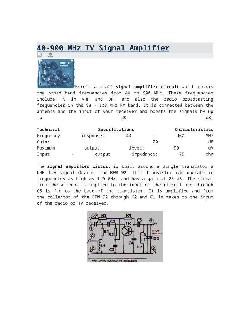
40-900 MHz TV Signal Amplifier |
Here's a small signal amplifier circuit which covers the broad band frequencies from 40 to 900 MHz. These frequencies include TV in VHF and UHF and also the radio broadcasting frequencies in the 88 - 108 MHz FM band. It is connected between the antenna and the input of your receiver and boosts the signals by up to 20 dB.

Technical Specifications -CharacteristicsFrequency response: 40 - 900 MHzGain: . 20 dBMaximum output level: 90 uVInput - output impedance: 75 ohm
The signal amplifier circuit is built around a single transistor a UHF low signal device, the BFW 92. This transistor can operate in frequencies as high as 1.6 GHz, and has a gain of 23 dB. The signal from the antenna is applied to the input of the circuit and through C5 is fed to the base of the transistor. It is amplified and from the collector of the BFW 92 through C2 and C1 is taken to the input of the radio or TV receiver.
The circuit operates off a small 9 V battery which, because of the very low power
consumption of the circuit, is going to last for a very long time.
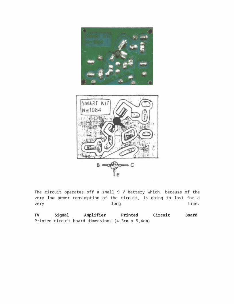
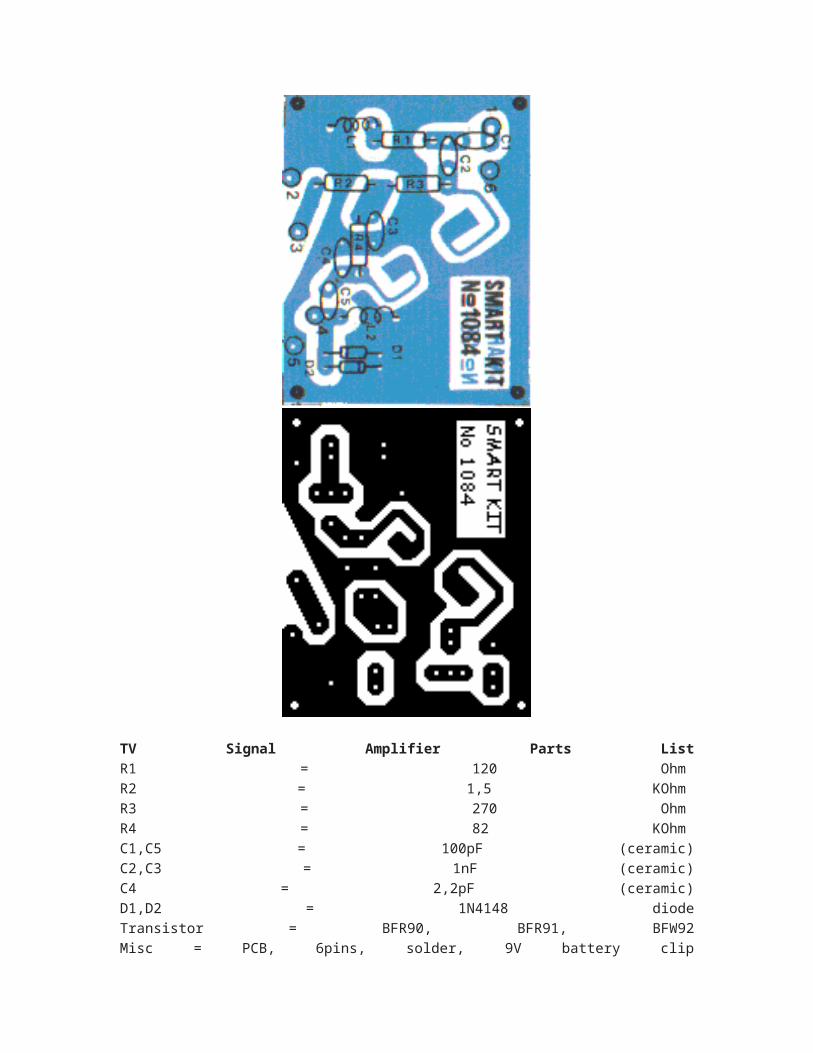
TV Signal Amplifier Printed Circuit Board
Printed circuit board dimensions (4,3cm x 5,4cm)
TV Signal Amplifier Parts List
R1 = 120 Ohm
R2 = 1,5 KOhm
R3 = 270 Ohm
R4 = 82 KOhm
C1,C5 = 100pF (ceramic)
C2,C3 = 1nF (ceramic)
C4 = 2,2pF (ceramic)
D1,D2 = 1N4148 diode
Transistor = BFR90, BFR91, BFW92
Misc = PCB, 6pins, solder, 9V battery clip
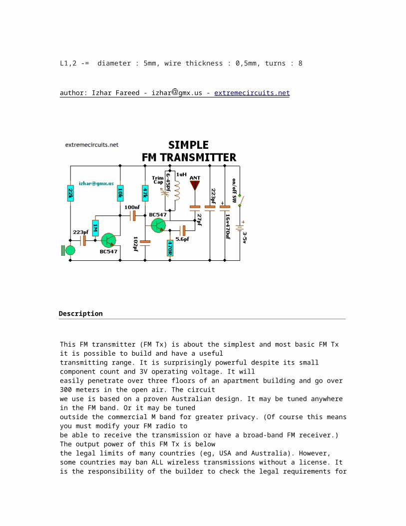
L1,2 -= diameter : 5mm, wire thickness : 0,5mm, turns : 8
author: Izhar Fareed - izhar gmx.us - extremecircuits.net
Description
This FM transmitter (FM Tx) is about the simplest and most basic FM Tx it is possible to build and have a usefultransmitting range. It is surprisingly powerful despite its small component count and 3V operating voltage. It willeasily penetrate over three floors of an apartment building and go over 300 meters in the open air. The circuit we use is based on a proven Australian design. It may be tuned anywhere in the FM band. Or it may be tuned outside the commercial M band for greater privacy. (Of course this means you must modify your FM radio tobe able to receive the transmission or have a broad-band FM receiver.) The output power of this FM Tx is below the legal limits of many countries (eg, USA and Australia). However, some countries may ban ALL wireless transmissions without a license. It is the responsibility of the builder to check the legal requirements for the operation of this circuit and to obey them.
CIRCUIT DESCRIPTION:
The circuit is basically a radio frequency (RF) oscillator that operates around 100 MHz. Audio picked up andamplified by the electret microphone is fed into the audio amplifier stage built around the first transistor. Outputfrom the collector is fed into the base of the second transistor where it modulates the resonant frequency ofthe tank circuit (the 5 turn coil and the trimcap) by varying the junction capacitance of the transistor. Junctioncapacitance is a function of the potential difference applied to the base of the transistor. The tank circuit isconnected in a Colpitts oscillator circuit.
CIRCUIT CALIBRATION:
Place the transmitter about 10 feet from a FM radio. Set the radio to somewhere about 89 - 90 MHz. Walk back tothe Fm Tx and turn it on. Spread the winding of the coil apart by approximately 1mm from each other. No coil winding should be touching another winding. Use a small screw driver to tune the trim cap. Remove the screwdriver from the trim screw after every adjustment so the LC circuit is not affected by stray capacitance. Or use a plastic screwdriver. If you have difficulty finding the transmitting frequency then have a second person tune up and down the FM dial after every adjustment. One full turn of the trim cap will cover its full range of capacitance from 6pF to 45pF. The normal FM band tunes in over about one tenth of the full range of the tuning cap. So it is best to adjust it in steps of 5 to 10 degrees at each turn. So tuning takes a little patience but is not difficult. The reason that there must be at least 10 ft. separation between the radio and the Tx is that the Tx emits harmonics; it does not only emit on one frequency but on several different frequencies close to each other.
NOTE:You may experiment with using 6V or 9V with the circuit to see how this increases the range of the transmitter. The sensitivity may be increased by lowering the 22K resistor to 10K. Try it and see.
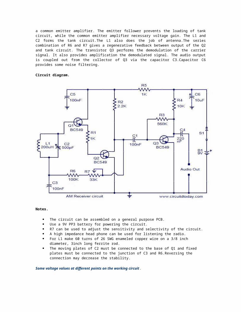
Description.
Here is a low cost AM receiver circuit that can be tuned from around 550 to 1100 KHz. Three transistors are used in this project. The transistors Q1 and Q2 are wired as a compound transistor pair in which Q1 is an emitter follower and Q2 is a common emitter amplifier. The emitter follower prevents the loading of tank circuit, while the common emitter amplifier necessary voltage gain. The L1 and C2 forms the tank circuit.The L1 also does the job of antenna.The series combination of R6 and R7 gives a regenerative feedback between output of the Q2 and tank circuit. The transistor Q3 performs the demodulation of the carrier signal. It also provides amplification the demodulated signal. The audio output is coupled out from the collector of Q3 via the capacitor C3.Capacitor C6 provides some noise filtering.
Circuit diagram.
Notes.
The circuit can be assembled on a general purpose PCB. Use a 9V PP3 battery for powering the circuit. R7 can be used to adjust the sensitivity and selectivity of the circuit. A high impedance head phone can be used for listening the radio. For L1 make 60 turns of 26 SWG enameled copper wire on a 3/8 inch diameter, 3inch long ferrite
rod. The moving plates of C2 must be connected to the base of Q1 and fixed plates must be connected
to the junction of C3 and R6.Reversing the connection may decrease the stability.
Some voltage values at different points on the working circuit.
Read more: http://www.circuitstoday.com/am-receiver-circuit#ixzz1AZORSvLS Under Creative Commons License: Attribution
Description.
This is a simple, but very useful circuit that can be used to transmit telephone conversations. When the telephone receiver is on hook the voltage across the lines will be about 48 volts. The preset R7 is so adjusted to obtain a 24.7 V across between the cathode of D2 and ground. At this voltage the Zener diode D2 will be in breakdown and the transistor T1 will conduct. This makes the transistor T2 OFF. When the receiver is off hook, the line voltage drops to about 11 volts. This makes the transistor T1 OFF and subsequently the T2 ON. The T2 in switched ON
condition will provide a DC path for the transistor T3 used in the FM transmitter section.
The transistor T3 is wired as a common emitter radio frequency oscillator. In simple words the transistor T2 serves as an ON/OFF switch for this oscillator. The modulated signal will be available at the collector of transistor T3 and the signal id fed to the antenna via capacitor C5.
Circuit diagram with Parts list.
Notes.
Assemble the circuit on a good quality PCB. For L1 make 45 turns of 36 SWG enameled copper wire on the resistor R6 itself. The resistor R6 must be a 1M, 1 watt resistor. For L2 make 3 turns of 21 SWG enameled copper wire on a 12 mm plastic former. For antenna, use a 1 meter insulated copper wire.
The capacitor C3 can be a 50pF trimmer.
Read more: http://www.circuitstoday.com/telephone-transmitter#ixzz1AZPvTRB9 Under Creative Commons License: Attribution