Vickers Vane Pumps Variable Displacement Vane Pumps for ... · Loads on drive shaft No radial or...
36
5137.00/EN/1198/A Variable Displacement Vane Pumps for Industrial Applications Model Series VVS and VVP Maximum Displacements to 100 cm 3 /r (6.1 in 3 /r) Maximum Pressures to 160 bar (2300 psi) Vickers ® Vane Pumps
-
Upload
trinhhuong -
Category
Documents
-
view
223 -
download
0
Transcript of Vickers Vane Pumps Variable Displacement Vane Pumps for ... · Loads on drive shaft No radial or...

5137.00/EN/1198/A
Variable Displacement Vane Pumpsfor Industrial ApplicationsModel Series VVS and VVP Maximum Displacements to 100 cm3/r (6.1 in3/r) Maximum Pressures to 160 bar (2300 psi)
Vickers®
Vane Pumps

2
Contents
Introduction 3
Series VVS Pumps 3. . . . . . . . . . . . . . . . . . . . . . . . . . . . . . . . . . . . . . . . . . . . . . . . . . . . . . . . . . . . . . . . . . . . . . . . . . . . . . . . . . . .
Model Code 5. . . . . . . . . . . . . . . . . . . . . . . . . . . . . . . . . . . . . . . . . . . . . . . . . . . . . . . . . . . . . . . . . . . . . . . . . . . . . . . . . . . . . .
Technical Data 6. . . . . . . . . . . . . . . . . . . . . . . . . . . . . . . . . . . . . . . . . . . . . . . . . . . . . . . . . . . . . . . . . . . . . . . . . . . . . . . . . . . . .
Two-stage Pressure Device 7. . . . . . . . . . . . . . . . . . . . . . . . . . . . . . . . . . . . . . . . . . . . . . . . . . . . . . . . . . . . . . . . . . . . . . . . . . .
Performance Characteristics
VVS0 8. . . . . . . . . . . . . . . . . . . . . . . . . . . . . . . . . . . . . . . . . . . . . . . . . . . . . . . . . . . . . . . . . . . . . . . . . . . . . . . . . . . . . . . . . .
VVS1 9. . . . . . . . . . . . . . . . . . . . . . . . . . . . . . . . . . . . . . . . . . . . . . . . . . . . . . . . . . . . . . . . . . . . . . . . . . . . . . . . . . . . . . . . . .
VVS2 10. . . . . . . . . . . . . . . . . . . . . . . . . . . . . . . . . . . . . . . . . . . . . . . . . . . . . . . . . . . . . . . . . . . . . . . . . . . . . . . . . . . . . . . . .
VVS3 11. . . . . . . . . . . . . . . . . . . . . . . . . . . . . . . . . . . . . . . . . . . . . . . . . . . . . . . . . . . . . . . . . . . . . . . . . . . . . . . . . . . . . . . . .
Dimensions
VVS0 12. . . . . . . . . . . . . . . . . . . . . . . . . . . . . . . . . . . . . . . . . . . . . . . . . . . . . . . . . . . . . . . . . . . . . . . . . . . . . . . . . . . . . . . . .
VVS1 13. . . . . . . . . . . . . . . . . . . . . . . . . . . . . . . . . . . . . . . . . . . . . . . . . . . . . . . . . . . . . . . . . . . . . . . . . . . . . . . . . . . . . . . . .
VVS2 & VVS3 14. . . . . . . . . . . . . . . . . . . . . . . . . . . . . . . . . . . . . . . . . . . . . . . . . . . . . . . . . . . . . . . . . . . . . . . . . . . . . . . . . .
Series VVP Pumps
Model Code 16. . . . . . . . . . . . . . . . . . . . . . . . . . . . . . . . . . . . . . . . . . . . . . . . . . . . . . . . . . . . . . . . . . . . . . . . . . . . . . . . . . . . .
Technical Data 18. . . . . . . . . . . . . . . . . . . . . . . . . . . . . . . . . . . . . . . . . . . . . . . . . . . . . . . . . . . . . . . . . . . . . . . . . . . . . . . . . . . .
Controls
Pressure Regulation 19. . . . . . . . . . . . . . . . . . . . . . . . . . . . . . . . . . . . . . . . . . . . . . . . . . . . . . . . . . . . . . . . . . . . . . . . . . . . .
Load sensing and Pressure Regulation 20. . . . . . . . . . . . . . . . . . . . . . . . . . . . . . . . . . . . . . . . . . . . . . . . . . . . . . . . . . . . . .
Performance Characteristics
VVP1 21. . . . . . . . . . . . . . . . . . . . . . . . . . . . . . . . . . . . . . . . . . . . . . . . . . . . . . . . . . . . . . . . . . . . . . . . . . . . . . . . . . . . . . . . .
VVP2 22. . . . . . . . . . . . . . . . . . . . . . . . . . . . . . . . . . . . . . . . . . . . . . . . . . . . . . . . . . . . . . . . . . . . . . . . . . . . . . . . . . . . . . . . .
VVP3 23. . . . . . . . . . . . . . . . . . . . . . . . . . . . . . . . . . . . . . . . . . . . . . . . . . . . . . . . . . . . . . . . . . . . . . . . . . . . . . . . . . . . . . . . .
Dimensions
VVP1 24. . . . . . . . . . . . . . . . . . . . . . . . . . . . . . . . . . . . . . . . . . . . . . . . . . . . . . . . . . . . . . . . . . . . . . . . . . . . . . . . . . . . . . . . .
VVP2 & VVP3 25. . . . . . . . . . . . . . . . . . . . . . . . . . . . . . . . . . . . . . . . . . . . . . . . . . . . . . . . . . . . . . . . . . . . . . . . . . . . . . . . . .
Series VVS and VVP Pumps
Dimensions – Base Mounted Pumps 27. . . . . . . . . . . . . . . . . . . . . . . . . . . . . . . . . . . . . . . . . . . . . . . . . . . . . . . . . . . . . . . . . . .
Combined Pumps
Pump Combinations 28. . . . . . . . . . . . . . . . . . . . . . . . . . . . . . . . . . . . . . . . . . . . . . . . . . . . . . . . . . . . . . . . . . . . . . . . . . . . . . .
Torque Requirements 30. . . . . . . . . . . . . . . . . . . . . . . . . . . . . . . . . . . . . . . . . . . . . . . . . . . . . . . . . . . . . . . . . . . . . . . . . . . . . . .
Dimensions 31. . . . . . . . . . . . . . . . . . . . . . . . . . . . . . . . . . . . . . . . . . . . . . . . . . . . . . . . . . . . . . . . . . . . . . . . . . . . . . . . . . . . . . .
Installation Instructions 35. . . . . . . . . . . . . . . . . . . . . . . . . . . . . . . . . . . . . . . . . . . . . . . . . . . . . . . . . . . . . . . . . . . . . . . . . . . . . .
� Eaton Hydraulics, Incorporated 2000 All Rights Reserved

3
Introduction
DescriptionVickers variable displacement vanepumps are available in four nominalsizes (0–1–2–3) and, are divided intothree displacements. Each size, whileretaining the same pump body, isavailable in two versions: low pressureVVS (100 bar, 1500 psi) with mechanical pressure regulator and highpressure VVP (160 bar, 2300 psi) withhydraulic pressure regulator. The rotor shaft of Vickers pumps ispre-arranged for mounting an additionalpump. By removing the rear cover,the secondary pump can be easilyattached (see items A and B on page4). Combining standard pumpseliminates the need for many “specialapplication” pumps.
As shown in the cross-sectional views,pumps consist of: (1) Body (2) One-piece shaft and rotor(3) Vanes (4) Pressure ring that changes the eccentricity and therefore the displacement of the pump, at
hydrostatic axial compensation(5) Pressure plate stator to provide
the passage of oil from the suction port to the pressure port
(6) Guide block balancing adjustment screw
(7) Displacement adjustment piston that regulates the maximum pressure compensated flow
(8) Maximum volume adjustment screw (optional feature – see model code page 5)
(9) Pressure regulator (10) Pressure regulator adjustment
Features & Benefits�Long pump life resulting from
manufacturing material characteristics,hydrodynamic lubrication of bearings,and hydrostatic balancing ofdistribution plates
�Quiet pump operation from 66 to 73 dBA
�Simplifies hydraulic circuit byeliminating maximum pressure reliefvalves and heat exchangers. Pumpscan be supplied with various pressureregulators to control the maximumsystem pressure.
�Standard ISO and SAE mountings�Combinations of standard pumps
provide flexibility and cost effectivepump packages.
Modular Construction
Basic pump
VVP hydraulic pressure compensator for pressure and flow controls
VVS mechanicalpressure compensator
VVS mechanical pressurecompensator with twostages of pressure (notavailable on VVS0)

4
VVP Pump
VVS Pump
10
9
1 2 3 4
876
5
10 9
1 2 3 4
6 7 8
5P
P
See descriptionon page 3.
See descriptionon page 3.
A B
A B

5
Series VVS Model Code
16
Mounting flange/port conn.
Variable vane pump
Frame size
0 – 6, 10, 12 cm3/r 1 – 16, 20, 25 cm3/r2 – 32, 40, 50 cm3/r3 – 63, 80, 100 cm3/r
Nominal size/geometricdisplacement, max. pressure
06 – 6 cm3/r10 – 10 cm3/r12 – 12 cm3/r16 – 16 cm3/r20 – 20 cm3/r 25 – 25 cm3/r32 – 31,5 cm3/r40 – 40 cm3/r50 – 50 cm3/r 63 – 63 cm3/r80 – 80 cm3/r100 – 100 cm3/r
Adjust. max. displacement stop
S – With stop (Omit if not required.)
10(03)
Electrical rating and wiringconnection (for CD pressurecontrol only)
01 – 220V AC 50 Hz with DIN 43650 plug connection
02 – 115V AC 60 Hz with 1/2” NPT conduit box
03 – 24V DC with DIN 43650 plug connection
(Omit if not required.)
Control pressure setting
A – 15–50 bar (215–700 psi) B – 30–80 bar (430–1200 psi)
(sizes 63–100 cm3/r)C – 30–100 bar ( 430–1500 psi)
(sizes 6–50 cm3/r)D – 80–150 bar (1200–2200 psi)
(sizes 6–12 cm3/r)
Control adjustment
W – Screw with locknutKL – Screw with key lock
Control design number
10 – For all models. Subject to change. Installation dimensions remain unaltered for designs 10–19.
Special features suffix
Rotation viewed from shaft end
R – Right hand (clockwise) only
Fluid compatibility
M – Mineral oilE – Phosphate esters
Pump design number
Subject to change. Installation dimensions remain unaltered fordesigns 30–39.
Pressure control
C – Standard pressure compensatorCD – Dual pressure compensator (only
available for 16–100 cm3/r)
3 4 5 876 91 2
1
2
3
5
6
7
8
9
10 11 12 13
10
11
12
R
13
**30 CDVVS R M D W
Code
Mounting flange Port connections
ISO 3019/2 with straight keyed shaft(size 0 is only available as a single orsecondary pump)
R
RF ISO 3019/2 with straight keyed shaft
PS
SAE B 4-bolt with straight keyed shaft(for size 1 pumps only)
PFSAE C 2-bolt with straight keyed shaft(only available on a primary or singlepump)
PX
ISO 3019/2 with straight keyed shaft(available only on secondary pump)
B Base plate mounting (available onlyas single pump)
G (BSPF) thread. (6–25 cm3/r pumps)
SAE 4-bolt flange with metric mounting bolts(31,5–100 cm3/r pumps)
SAE UNF thread. (6–25 cm3/r pumps)
SAE 4-bolt flange with UNC mounting bolts(31,5–100 cm3/r pumps)
O-ring sealed (16–100 cm3/r pumps)
SAE 4-bolt flange with UNC mounting bolts(31,5–100 cm3/r pumps)
Maximum150 bar(2200 psi)
Maximum100 bar(1500 psi)
Maximum80 bar(1200 psi)
4
14
(S)
14
Note: See page 34 for detailed dimensional listing for mounting flanges, shafts and ports.
ISO 3019/2 with straight keyed shaft(for size 0 pumps only). Size 0 is onlyavailable as a single or secondarypump.
1

6
Series VVS Technical Data
Nominal size Size 0 Size 1 Size 2 Size 3
Displacement according to ISO 3662 – cm3/r (in3/r)6 (0.366)10 (0.610)12 (0.732)
16 (0.976)20 (1.220)25 (1.526)
31,5 (1.922)40 (2.441)50 (3.051)
63 (3.845)80 (4.882)100 (6.102)
Actual displacement – cm3/r (in3/r)6,9 (0.421)11 (0.671)13,1 (0.799)
17,9 (1.092)22,1 (1.349)26,9 (1.642)
34,5 (2.105)42,8 (2.612)53,1 (3.240)
69 (4.211)86,2 (5.260)105,5 (6.438)
Mounting flange type (See model code, page 5.)ISO 3019/2SAE 4-bolt
ISO 3019/2SAE 4-boltBase plate
ISO 3019/2SAE C 2-boltBase plate
ISO 3019/2SAE C 2-boltBase plate
Maximum working pressure – bar (psi) 150 (2200) 100 (1500) 100 (1500) 80 (1200)
Allowed maximum drain port pressure – bar (psi) 1 (15)
Inlet pressure (absolute) – bar (psi) 0,5 to 1,5 (7 to 22)
Speed range – r/min 800 to 1800
Rotation direction (viewed from shaft end) Right-hand (clockwise)
Loads on drive shaft No radial or axial loads allowed
Maximum torque on primary shaft – Nm (lb-in)(See pages 28 and 30 for torque requirements ofcombined pumps.)
110 (974) 197 (1744) 400 (3540) 740 (6550)
Hydraulic fluid Mineral oil – HM according to ISO 3498 – Phosphate Ester
Viscosity range at working temperature – mm2/s (cSt) 23 to 45
Recommended viscosity – mm2/s (cSt) at 50�C (122�F) 32
Viscosity index 100 minimum
Fluid temperature range – �C (�F) –10 to 70 (14 to 158)
Maximum fluid contamination level Class 9 per NAS 1638, or class 18/15 per ISO 4406
Weight – kg (lb) 6,5 (14.3) 12 (26.5) 32 (70.5) 44 (97)
In case of different operating conditions, contact Vickers.

7
Two-stage Pressure Device for VVS Pumps
Advantages of hydraulic circuit withtwo-stage pressure adjustment:� Two pressure settings allow pump to
reduce power consumption requiredwhen working against a closed-centerhydraulic valve system
� Pump will compensate at the lowerpressure setting with no pilot flow loss.
� Allows the use of hydraulic valves with“all closed” neutral positions
� Allows several different pressuresettings to be used
� Pump has a longer effective workinglife with less downtime
Pump with two-stage pressure device
P

8
VVS0 Performance Characteristics
Power consumption with zero flow setting
Power consumption with maximum flow
Performance with: speed 1450 r/min;oil per ISO 3498;visc. 32 mm2/s (cSt);temp. 50�C (122�F)
VVS0-06
VVS0-10
VVS0-12
VVS0-06, -10, -12
VVS0-06, -10, -12
VVS0-06, -10, -12
Values established with zero flow setting
Typical noise level
Response time and pressure peak (Test from Q max Qo - Qo Q max)
25(350)
50(700)
75(1100)
100(1500)
125(1850)
150(2200)
Operating pressure - bar (psi)
25(350)
50(700)
75(1100)
100(1500)
125(1850)
150(2200)
Operating pressure - bar (psi)
25(350)
50(700)
75(1100)
100(1500)
125(1850)
150(2200)
Operating pressure - bar (psi)
25(350)
50(700)
75(1100)
100(1500)
125(1850)
150(2200)
Operating pressure - bar (psi)
25(350)
50(700)
75(1100)
100(1500)
125(1850)
150(2200)
Operating pressure - bar (psi)
0
2 (0.53)
4 (1.06)
6 (1.59)
8 (2.11)
10 (2.64)
12 (3.17)
14 (3.70)
Flo
w -
L/m
in (
US
gpm
)
0
3 (0.79)
6 (1.59)
9 (2.38)
12 (3.17)
15 (3.96)
18 (4.76)
21 (5.55)
Flo
w -
L/m
in (
US
gpm
)
3 (0,79)
6 (1,59)
9 (2.38)
12 (3.17)
15 (3.96)
18 (4.76)
21 (5.55)
Flo
w -
L/m
in (
US
gpm
)
Dra
inag
e -
L/m
in (
US
gpm
)
0,5 (0.13)
1 (0.26)
1,5 (0.40)
2 (0.53)
2,5 (0.66)
Noi
se le
vel d
B(A
)
56
58
60
62
64
66
Pre
ssur
e -
bar
(psi
)
50 (700)100 (1500)150 (2200)200 (2900)
0
250 (3600)
0
0
0 Time (msec)(Time scale - 50 msec indexing
Pressure peaks are due to testcircuit. Peaks exceeding 30% ofthe max. operating pressure shallbe eliminated.
Inpu
t pow
er -
kW
(hp
)
1,5 (2.01)
3 (4.02)
4,5 (6.03)
6 (8.05)
1 (1.34)
2 (2.68)
3 (4.02)
4 (5.36)
1,5 (2.01)
3 (4.02)
4,5 (6.03)
6 (8.05)
Inpu
t pow
er -
kW
(hp
)In
put p
ower
- k
W (
hp)

9
VVS1 Performance Characteristics
3 (4.02)
4 (5.36)
100(1500)
Performance with: Speed 1450 r/min;Oil per ISO 3498;Visc. 32 mm2/s (cSt);Temp. 50�C (122�F)
VVS1-16
VVS1-20
VVS1-25
VVS1-16, -20, -25
VVS1-16, -20, -25
VVS1-16, -20, -25
Values established with zero flow setting
Typical noise level
Response time and pressure peak(Test from Q max Qo - Qo Q max)
20(300)
40(600)
60(900)
80(1200)
Operating pressure - bar (psi)
Operating pressure - bar (psi)
20(300)
40(600)
60(900)
100(1500)
80(1200)
Operating pressure - bar (psi)
20(300)
40(600)
60(900)
100(1500)
80(1200)
Operating pressure - bar (psi)
0
5 (1.32)
10 (2.64)
15 (3.96)
20 (5.28)
25 (6.60)
30 (7.93)
Flo
w -
L/m
in (
US
gpm
)F
low
- L
/min
(U
Sgp
m)
Flo
w -
L/m
in (
US
gpm
)
Dra
inag
e -
L/m
in (
US
gpm
)
0,5 (0.13)
1 (0.26)
1,5 (0.40)
2 (0.53)
2,5 (0.66)
Noi
se le
vel d
B(A
)
68
62
64
66
Pre
ssur
e -
bar
(psi
)
50 (700)
100 (1500)
150 (2200)
200 (2900)
0
250 (3600)
0
0
Time (msec)(Time scale - 50 msec indexing
Pressure peaks are due to test circuit. Peaks exceeding 30% of the max.
operating pressure shall be eliminated.
Inpu
t pow
er -
kW
(hp
)
1 (1.34)
2 (2.68)
Inpu
t pow
er -
kW
(hp
)In
put p
ower
- k
W (
hp)
5 (6.71)
6 (8.05)
35 (9.25)
10 (2.64)
15 (3.96)
20 (5.28)
25 (6.60)
30 (7.93)
3 (4.02)
4 (5.36)
1 (1.34)
2 (2.68)
5 (6.71)
6 (8.05)6 (8.05)
7 (9.39)
0 100(1500)
20(300)
40(600)
60(900)
80(1200)
Operating pressure - bar (psi)
10 (2.64)
40 (10.57)
20 (5.28)
30 (7.93)
100(1500)
20(300)
40(600)
60(900)
80(1200)
0
3 (4.02)
4 (5.36)
1 (1.34)
2 (2.68)
5 (6.71)
6 (8.05)6 (8.05)
7 (9.39)300 (4350)
8 (10.73)
Power consumption with zero flow setting
Power consumption with maximum flow

10
VVS2 Performance Characteristics
4 (5.36)
1 (1.34)
2 (2.68)
6 (8.05)
8 (10.73)
10 (13.41)
12 (16.09)
14 (18.77)
4 (5.36)
100(1500)
Performance with: Speed 1450 r/min;Oil per ISO 3498;Visc. 32 mm2/s (cSt);Temp. 50�C (122�F)
VVS2-32
VVS2-40
VVS2-50
VVS2-32, -40, -50
VVS2-32, -40, -50
VVS2-32, -40, -50
Values established with zero flow setting
Typical noise level
Response time and pressure peak(Test from Q max Qo - Qo Q max)
20(300)
40(600)
60(900)
80(1200)
Operating pressure - bar (psi)
Operating pressure - bar (psi)
20(300)
40(600)
60(900)
100(1500)
80(1200)
Operating pressure - bar (psi)
20(300)
40(600)
60(900)
100(1500)
80(1200)
Operating pressure - bar (psi)
0
10 (2.64)
20 (5.28)
30 (7.93)
Flo
w -
L/m
in (
US
gpm
)F
low
- L
/min
(U
Sgp
m)
Flo
w -
L/m
in (
US
gpm
)
Dra
inag
e -
L/m
in (
US
gpm
)
1 (0.26)
2 (0.53)
Noi
se le
vel d
B(A
)
70
64
66
68
Pre
ssur
e -
bar
(psi
)
50 (700)
100 (1500)
150 (2200)
200 (2900)
0
250 (3600)
0
0
Time (msec)(Time scale - 50 msec indexing
Pressure peaks are due to test circuit. Peaks exceeding 30% of the max.
operating pressure shall be eliminated.
Inpu
t pow
er -
kW
(hp
)
2 (2.68)
Inpu
t pow
er -
kW
(hp
)In
put p
ower
- k
W (
hp)
6 (8.05)
0 100(1500)
20(300)
40(600)
60(900)
80(1200)
Operating pressure - bar (psi)
15 (3.96)
60 (15.85)
30 (7.93)
45 (11.89)
100(1500)
20(300)
40(600)
60(900)
80(1200)
0
2 (2.68)
5 (6.71)
8 (10.73)
11 (14.75)
300 (4350)14 (18.77)
40 (10.57)
50 (13.21)
60 (15.85)
8 (10.73)
10 (13.41)
12 (16.09)
3 (0.79)
4 (1.06)
5 (1.32)
50 (13.21)
40 (10.57)
20 (5.28)
30 (7.93)
60 (15.85)
70 (18.49)
75 (19.81)
90 (23.78)
17 (22.80)
Power consumption with zero flow setting
Power consumption with maximum flow

11
VVS3 Performance Characteristics
3 (4.02)
15 (20.12)
23 (30.84)
72
66
68
70
80(1200)
Performance with: Speed 1450 r/min;Oil per ISO 3498;Visc. 32 mm2/s (cSt);Temp. 50�C (122�F)
VVS3-63
VVS3-80
VVS3-100
VVS3-63, -80, -100
VVS3-63, -80, -100
VVS3-63, -80, -100
Values established with zero flow setting
Typical noise level
Response time and pressure peak(Test from Q max Qo - Qo Q max)
20(300)
35(500)
50(700)
80(1200)
Operating pressure - bar (psi)
Operating pressure - bar (psi)
Operating pressure - bar (psi)
Operating pressure - bar (psi)
0
20 (5.28)Flo
w -
L/m
in (
US
gpm
)F
low
- L
/min
(U
Sgp
m)
Flo
w -
L/m
in (
US
gpm
)
Dra
inag
e -
L/m
in (
US
gpm
)
1 (0.26)
2 (0.53)
3 (0.79)
4 (1.06)
5 (1.32)
Noi
se le
vel d
B(A
)
Pre
ssur
e -
bar
(psi
)
20 (300)
80 (1200)
140 (2000)
200 (2900)
0
260 (3800)
0
0
Time (msec)(Time scale - 50 msec indexing
Pressure peaks are due to test circuit. Peaks exceeding 30% of the max.
operating pressure shall be eliminated.
Inpu
t pow
er -
kW
(hp
)In
put p
ower
- k
W (
hp)
Inpu
t pow
er -
kW
(hp
)
0
Operating pressure - bar (psi)
60 (15.85)
30 (7.93)
0
320 (4600)
20(300)
35(500)
65(900)
50(700)
5 (6.71)
10 (13.41)
15 (20.12)
40 (10.57)
60 (15.85)
25 (6.60)
50 (13.21)
75 (19.81)
90 (23.76) 20 (26.82)
25 (33.53)
3 (4.02)
6 (8.05)
12 (16.09)
15 (20.12)
9 (12.07)
18 (24.14)
65(900)
20(300)
35(500)
50(700)
80(1200)
65(900)
80(1200)
20(300)
35(500)
65(900)
50(700)
100 (26.42)
125 (33.03)
7 (9.39)
11 (14.75)
19 (25.48)
80 (21.13)
100 (26.42)
120 (31.70)
150 (39.63)
120 (31.70)
150 (39.63)
180 (47.55)
30 (40.23)
20(300)
35(500)
50(700)
80(1200)
65(900)
Power consumption with zero flow setting
Power consumption with maximum flow

12
Dimensions - VVS0 with ISO Mounting Flange
8(0.31)
W
7(0.28)
Case drain port“J” thread
Pressure adjustmentscrew. Turning clockwiseincreases pressure.
Dimensions in millimeters (inches)
60(2.36)
7 x 7 (0.28 x 0.28)adjuster of maximumdisplacement stop(optional feature –see model code)
Outlet port“D” thread
55 (2.17)
87 (3.43)
180(7.09)
35 (1.38)30 (1.18)
GG
104 (4.09)87 (3.43)
Ø 103(4.06)
115(4.53)
65(2.56)
28 (1.10) max.
70 (2.76)
94 (3.70)
Ø 9(0.35)
N
Ø 80(3.15)
Ø AA
JJ
45 (1.77)
Identificationplate
Inletport“DD” thd.
“C” control with “W” adjustment
Note:1. Dual pressure control “CD” is not available on VVS0 frame size. 2. All mounting flange, port and shaft options are listed on page 34.
Pressure adjustment knob.Turning clockwise increasespressure.
“C” control with “KL” adjustment
170(6.69)
60(2.36)
Mounting flangeand ports code* D J N W Ø AA DD GG JJ
R 3/8 BSP 1/4 BSP 6 (0.236) 22,5 (0.886) 20 (0.787) 1/2 BSP 148 (5.83) 44 (1.73)
PS .750-16UNF-2B
.500-20UNF-2B 4,76 (0.187) 17,9 (0.705) 15,88 (0.625) .875-14
UNF-2B 136 (5.35) 32 (1.25)
* See model code, page 5.

13
Dimensions - VVS1 with ISO or SAE Mounting Flange
Note: All mounting flange, port and shaft options are listed on page 34.
PP
19 (0.79)
10.3(0.41)
Ø AA
26(1.02)
34 (1.34)max.
Pressure adjustment screw.Turning clockwise increasespressure.
Dimensions in millimeters (inches)
70 (2.75)26 (1.02)
Outlet port“D” thread
66 (2.60) 66 (2.60)
30 (1.18) max.
213(8.38)
131(5.16)
82(3.23)
80 (3.15)
120(4.72)
Ø 11(0.43)
N
120 (4.72)
WØ V
Inlet port“DD” thread
Casedrain port“J” thread
125 (4.92)JJ
11 (0.39)
GG159 (6.25)
182(3.23)9
(0.35)
Ø BB
89(3.50)
241(9.49)
159(6.26)
32,5 (1.28)26,6 (1.05)
60 (2.36)
CETOP 03 valvemounted here
Identification plate
16,3 (0.64)6 (0.24)
31 (1.22) 40,5 (1.59)
PT
“C” control with “W” adjustment
“CD” control with “W” adjustment
7 x 7 (0.28 x 0.28)adjuster of maximumdisplacement stop(optional feature –see model code)
Pressure adjustment knob.Turning clockwise increasespressure.
“CD” control
60 (2.36)
191(7.52)
60 (2.36)
“KL” adjustment
“C” control
214(8.43)
Mounting flangeand ports code* D J N ØV W AA ØBB DD GG JJ
R (ISO) 3/4 BSP 3/8 BSP 8(0.315)
125(4.921)
28(1.102)
25(0.984)
100(3.937) 1 BSP 205
(8.07)46(1.81)
PS (SAE) 1.0625-12UNF-2B
.5625-18UNF-2B
6,35(0.250)
127(5.000)
28,17(1.109)
25,4(1.000)
101,6(4.000)
1.3125-12UNF-2B
207(8.15)
48(1.89)
* See model code, page 5.

14
Dimensions - VVS2 & VVS3 with ISO Mounting Flange
Note: All mounting flange, port and shaft options are listed on page 34.
Outlet portØ D
W A
E
Dimensions in millimeters (inches).
19 (0.79)
10.3(0.41)
32,5 (1.28)26,6 (1.05)
16,3 (0.64)6 (0.24)
31 (1.22) 40,5 (1.59)
Case drain“J” thread
Pressure adjustment screw.Turning clockwise increasespressure.
Identification plate
10 x 10 (0.39 x 0.39)adjuster of maximumdisplacement stop(optional feature –see model code)
67 (2.64)
CETOP 03 valvemounted here
P
63 (2.48)
63 (2.48)
BC
40 (1.57) max.
FØ M
N
Ø V
Y
ZAA
Inlet portØ DD
FFGG
9 (0.35)
PP
PT
45 (1.77)
10 (0.39)
JJ
K K
H
G
R
RU
T
X
BB
EE
CC
HH
SL
“C” control with “W” adjustment
“CD” control with “W” adjustment
“C” control
60 (2.36)
LL
“KL” control adjustment
60 (2.36)
Pressure adjustment knob.Turning clockwise increasespressure.
“CD” control
KK
Case drain“J” thread
Model A B C Ø D E F G H J K L Ø M N P R S
VVS2 52,4(2.06)
26,2(1.03)
30(1.18)
25(0.98)
M10 or.375-16UNC-2B*
285(11.22)
175(6.89)
110(4.33)
1/2 BSP or.875-14UNF-2B*
95(3.74)
122(4.80)
14(0.55)
10(0.39)
M12 or.500-13UNC-2B*
150(5.91)
147(5.79)
VVS3 58,7(2.31)
30.2(1.19)
36(1.42)
32(1.26)
M10 or.4375-14UNC-2B*
305(12.01)
185(7.28)
120(4.72)
1/2 BSP or.875-14UNF-2B*
105(4.13)
132(5.20)
18(0.71)
12(0.47)
M12 or.500-13UNC-2B*
185(7.28)
157(6.18)
* See mounting flange/port connections codes RF and PX, page 5.
Model T U Ø V W X Y Z Ø AA Ø BB CC Ø DD EE FF GG HH JJ KK LL
VVS2 115(4.53)
113(4.45)
160(6.30)
35(1.38)
35,7(1.41)
40(1.51)
70(2.76)
32(1.26)
125(4.92)
207(8.15)
38(1.50)
91(3.58)
220(8.66)
280(11.02)
317(12.48)
60(2.36)
267(10.51)
235(9.25)
VVS3 125(4.92)
123(4.84)
200(7.87)
43(1.69)
43(1.69)
46(1.81)
77,8(3.06)
40(1.57)
160(6.30)
217(8.54)
51(2.01)
105(4.13)
245(9.65)
313(12.32)
337(13.27)
68(2.68)
277(10.91)
245(9.65)

15
Dimensions - VVS2 & VVS3 with SAE Mounting Flange
C
Note: All mounting flange, port and shaft options are listed on page 34.
Dimensions in millimeters (inches).
A
B
Outlet port Ø D
Identification plate
E thread
F
G
H
U
K K
18(0.71)
LS
X
9 (0.35)
Y
Z
T
EE
Inlet portØ DD
FF
GG
HH
CC
32,5 (1.28)
26,6 (1.05)
16,3 (0.64)
19 (0.75)
6 (0.24)
40,5 (1.59)
10,3 (0.41)
67 (2.64)
31 (1.22)
10 x 10 (0.39 x 0.39)adjuster of maximumdisplacement stop(optional feature –see model code)
34,5(1.36)
58 (2.28)
10 (0.39)
Case drain.875-14 UNF-2B
.500-13 UNC-2B
Ø 127(5.00)
Ø 31,75(1.25)
CETOP 03 valvemounted here63 (2.48)
“C” control with “W” adjustment
“CD” control with “W” adjustment “KL” control adjustmentPressure adjustment knob.Turning clockwise increasespressure.
“C” control
“CD” control
60(2.36)
60(2.36)
LL
KK
40 (1.57) max
210(8.27)
Ø 181(7.13)
Key 6,35(0.25) wide
63 (2.48)
45 (1.77)
Model A B C Ø D E F G H K L S T
VVS2 52,4(2.06)
26,2(1.03)
27(1.06)
25(0.98) .375 UNC 285
(11.22)175(6.89)
110(4.33)
95(3.74)
122(4.80)
147(5.79)
115(4.53)
VVS3 58,7(2.31)
30.2(1.19)
35(1.38)
32(1.26) .4375 UNC 305
(12.01)185(7.28)
120(4.72)
105(4.13)
132(5.20)
157(6.18)
125(4.92)
Model U X Y Z CC Ø DD EE FF GG HH KK LL
VVS2 113(4.45)
35,7(1.41)
40(1.51)
70(2.76)
207(8.15)
38(1.50)
91(3.58)
220(8.66)
280(11.02)
317(12.48)
267(10.51)
235(9.25)
VVS3 123(4.84)
43(1.69)
46(1.81)
77,8(3.06)
217(8.54)
51(2.01)
105(4.13)
245(9.65)
313(12.32)
337(13.27)
277(10.91)
245(9.65)

16
Series VVP Model Code
Mounting flange/port conn.
Mounting flange Port connections ISO 3019/2 with straight keyed
shaft
SAE B 4-bolt with straight keyedshaft
SAE C 2-bolt with straight keyedshaft (available only on primaryor single pump)
ISO 3019/2 with straight keyedshaft (available only onsecondary pump)
Base plate mounting (availableonly as single pump)
G (BSPF) thread. (16–25 cm3/r pumps)
SAE 4-bolt flange with metric mountingbolts (31,5–100 cm3/r pumps)
SAE UNF thread. (16–25 cm3/r pumps)
SAE 4-bolt flange with UNC mountingbolts (31,5–100 cm3/r pumps)
O-ring sealed (16–100 cm3/r pumps)
SAE 4-bolt flange with UNC mountingbolts (31,5–100 cm3/r pumps)
ISO 3019/2 with straight keyedshaft
Code R
RF PS
PF
PX
B
Variable vane pump
Frame size
1 – 16, 20, 25 cm3/r2 – 32, 40, 50 cm3/r3 – 63, 80, 100 cm3/r
Nominal size/geometricdisplacement, maximum
16 – 16 cm3/r20 – 20 cm3/r 25 – 25 cm3/r32 – 31,5 cm3/r40 – 40 cm3/r50 – 50 cm3/r 63 – 63 cm3/r80 – 80 cm3/r100 – 100 cm3/r
Adjust. max. displacement stop
S – With stop(Omit if not required.)
15(03)
Rotation viewed from shaft end
R – Right hand (clockwise) only
Fluid compatibility
M – Mineral oilE – Phosphate esters
Pump design number
Subject to change. Installationdimensions remain unaltered for designs30–39.
3 4 5 8761 2
1
2
3
5
6
7
1 R
8
*30 CVTCEVVP 20 R M B
Maximum160 bar(2300 psi)
Maximum150 bar(2200 psi)
10 **(S)
4
Note: See page 34 for detailed dimensional listing for mounting flanges, shafts and ports.
04

17
30M 15(03)
9
1
10 11 12 13
R *CVTCEVVP 20 R B 10
14
**(S)
15
04
16
Control pressure setting
B – 30–160 bar (430–2300 psi) (sizes 16–50 cm3/r
C – 30–150 bar (430–2200 psi) (sizes 63–100 cm3/r
Control adjustment
Omit for CR, CE, CVPR, CVTD,CVPCE and CVTCE pump controls.K – Micrometer knob (standard)KL – Micrometer knob with key lock
Maximum power setting in kW
Applies to CVT pump control only.** – Factory setting of power limit in
kilowatt; for example 04=4 kW
Maximum pressure setting
Applies to CVT pump control only.** – Factory setting of pressure for
zero flow in 10-bar increments; for example 15=150 bar
Control design number
10 – For all models. Subject to change.Installation dimensions remain unaltered for designs 10–19.
Special features suffix
Pump controls
C – Standard pressure compensator
CR – Remote controlled pressure control
CD1 – Dual pressure control with non-adjustable min. pressure
CD2 – Dual adjustable pressure control
CE – Proportional pressure controlCVP – Load sensing compensatorCVPR –Remote controlled load
sensing controlCVPD1–Load sensing control with dual
pressure with fixed minimum pressure
CVPD2–Load sensing control with dualadjustable pressure control
CVPCE–Load sensing control with proportional pressure control
CVT – Torque limiterCVTR – Remote controlled torque
limiterCVTD – Torque control with dual
adjustable pressure controlCVTCE–Torque control with
proportional pressure control
Electrical rating andwiring connection
For CD*, CVPD*, CVTD pump controls,three options below apply; for CE,CVPCE, CVTCE, only option 03applies.01 – 220V AC 50 Hz with DIN 43650
plug connection 02 – 115V AC 60 Hz with 1/2” NPT
conduit box03 – 24V DC with DIN 43650 plug
connection
(Omit if not required.)
9 11
12
13
14
15
10
16

18
Series VVP Technical Data
Nominal size Size 1 Size 2 Size 3
Displacement according to ISO 3662 – cm3/r (in3/r)16 (0.976)20 (1.220)25 (1.526)
31,5 (1.922) 40 (2.441)50 (3.051)
63 (3.845) 80 (4.882)100 (6.102)
Actual displacement – cm3/r (in3/r)17,9 (1.092)22,1 (1.349)26,9 (1.642)
34,5 (2.105)42,8 (2.612)53,1 (3.240)
69 (4.211)86,2 (5.260)105,5 (6.438)
Mounting flange type (See model code, page 16.)ISO 3019/2SAE 4-boltBase plate
ISO 3019/2SAE C 2-boltBase plate
ISO 3019/2SAE C 2-boltBase plate
Maximum working pressure – bar (psi) 160 (2300) 160 (2300) 150 (2200)
Allowed maximum drain port pressure – bar (psi) 1 (15)
Inlet pressure (absolute) – bar (psi) 0,5 to 1,5 (7 to 22)
Speed range – r/min 800 to 1800
Rotation direction (viewed from shaft end) Right-hand (clockwise)
Loads on drive shaft No radial or axial loads allowed
Maximum torque on primary shaft – Nm (lb-in)(See pages 28 and 30 for torque requirements ofcombined pumps.)
197 (1744) 400 (3540) 740 (6550)
Hydraulic fluid Mineral oil – HM according to ISO 3498 – Phosphate Ester
Viscosity range at working pressure– mm2/s (cSt) 23 to 45
Recommended viscosity – mm2/s (cSt) at 50�C (122�F) 32
Viscosity index 100 minimum
Fluid temperature range – �C (�F) –10 to 70 (14 to 158)
Maximum fluid contamination level Class 9 per NAS 1638, or class 18/15 per ISO 4406
Weight – kg (lb) 13 (28.7) 33 (72.8) 45 (99.2)
In case of different operating conditions, contact Vickers.

19
Controls for VVP Pumps
VVP pumps offer a wide selection ofelectrohydraulic controls for theregulation of pressure and volume. In addition to the various pressureregulating controls, a hydraulicload-sensing control is available toprovide pumps with maximum flexibilityfor use in energy saving systems.
Pump with standard pressure compensator
Pump with remote pressure control
Pump with two stages of pressureof which one with fixed setting (atminimum pressure level of pump)
Modelcode CD1
Modelcode C
Pump with two adjustable stages of pressure
Pump with proportional pressure control Modelcode CE
Modelcode CD2
Modelcode CR
Remote max. pressure relief valve from 0 to 5 L/min (0 to 1.3USgpm) not supplied. Length of pilot line between compensatorand relief valve should not exceed 5 m (16 ft).
Q
P
Q
P
Q
P
Q
P
Q
P
The load sensing compensator controlreceives a signal pressure directly afteran external throttle and before anactuator. When a variation in pressureis sensed (with a fixed fall in pressure�P=20 bar (300 psi), the control willautomatically change the pump’sdisplacement independent of pressurevariations that occur in the circuit.
Diagrams and Characteristic Curvesfor Pressure Regulation
The load sensing control producesa notable reduction in displacedpower and is recommended for usein applications where there arenotable variations in torque (or force)and speed.

20
Controls for VVP Pumps
Double pressure loadsense device
Load sensing pump for standardflow control
Load sensing pump with remotepressure control
Load sensing pump with two stages ofpressure of which one with fixed setting(at min. pressure level of pump)
Model codeCVPD1
Modelcode CVP
Load sensing ump with two adjustablestages of pressure
Load sensing pump with proportionalpressure control Model code
CVPCEModel codeCVPR
Max. pressure relief valve from 0 to 5 L/min (0 to 1.3 USgpm)not supplied. Length of pilot line between compensator andrelief valve should not exceed 5 m (16 ft).
Q
P
Q
Diagrams and Characteristic Curves for Load Sensing and Pressure Regulation
Model codeCVPD2
P
Q
Q
Q
P
P
P
Manual or electroproportionalthrottle (not supplied)
Manual or electroproportionalthrottle (not supplied)
Manual or electroproportionalthrottle (not supplied)
Manual or electroproportionalthrottle (not supplied)
Manual or electroproportionalthrottle (not supplied)
Standard loadsense device
Double pressure load sense device
Double pressure load sense device
Double pressure loadsense device

21
VVP1 Performance Characteristics
140(2000)
60(900)
100(1500)
72
66
68
70
80(1200)
120(1750)
4 (5.36)
100(1500)
Performance with: Speed 1450 r/min;Oil per ISO 3498;Visc. 32 mm2/s (cSt);Temp. 50�C (122�F)
VVP1-16
VVP1-20
VVP1-25
VVP1-16, -20, -25
VVP1-16, -20, -25
VVP1-16, -20, -25
Values established with zero flow setting
Typical noise level
Response time and pressure peak(Test from Q max Qo - Qo Q max)
20(300)
40(600)
60(900)
80(1200)
Operating pressure - bar (psi)
Operating pressure - bar (psi)
Operating pressure - bar (psi)
Operating pressure - bar (psi)
0
5 (1.32)
10 (2.64)
15 (3.96)
20 (5.28)
25 (6.60)
30 (7.93)
Flo
w -
L/m
in (
US
gpm
)F
low
- L
/min
(U
Sgp
m)
Flo
w -
L/m
in (
US
gpm
)
Dra
inag
e -
L/m
in (
US
gpm
)
1,5 (0.40)
3 (0.79)
4,5 (1.19)
6 (1.59)
7,5 (1.98)
Noi
se le
vel d
B(A
)
Pre
ssur
e -
bar
(psi
)
40 (600)
100 (1500)
160 (2300)
220 (3200)
0
280 (4000)
0
0
Time (msec)(Time scale - 50 msec indexing
Pressure peaks are due to test circuit. Peaks exceeding 30% of the max.
operating pressure shall be eliminated.
Inpu
t pow
er -
kW
(hp
)
2 (2.68)
Inpu
t pow
er -
kW
(hp
)In
put p
ower
- k
W (
hp)
6 (8.05)
35 (9.25)
10 (2.64)
15 (3.96)
20 (5.28)
25 (6.60)
30 (7.93)
4 (5.36)
2 (2.68)
8 (10.73)
6 (8.05)
12 (16.09)
0
Operating pressure - bar (psi)
10 (2.64)
40 (10.57)
20 (5.28)
30 (7.93)
0
340 (4900)
120(1750)
140(2000)
160(2300)
100(1500)
20(300)
40(600)
60(900)
140(2000)
160(2300)
8 (10.73)
100(1500)
20(300)
40(600)
60(900)
80(1200)
120(1750)
140(2000)
160(2300)
10 (13.41)
80(1200)
120(1750)
20(300)
40(600)
160(2300)
100(1500)
20(300)
40(600)
60(900)
80(1200)
120(1750)
140(2000)
160(2300)
4 (5.36)
2 (2.68)
8 (10.73)
6 (8.05)
12 (16.09)
10 (13.41)
Power consumption with zero flow setting
Power consumption with maximum flow

22
VVP2 Performance Characteristics
3 (4.02)
6 (8.05)
12 (16.09)
15 (20.12)
9 (12.07)
18 (24.14)
21 (28.16)
140(2000)
60(900)
100(1500)
74
68
70
72
80(1200)
120(1750)
100(1500)
Performance with: Speed 1450 r/min;Oil per ISO 3498;Visc. 32 mm2/s (cSt);Temp. 50�C (122�F)
VVP2-32
VVP2-40
VVP2-50
VVP2-32, -40, -50
VVP2-32, -40, -50
VVP2-32, -40, -50
Values established with zero flow setting
Typical noise level
Response time and pressure peak(Test from Q max Qo - Qo Q max)
20(300)
40(600)
60(900)
80(1200)
Operating pressure - bar (psi)
Operating pressure - bar (psi)
Operating pressure - bar (psi)
Operating pressure - bar (psi)
0
10 (2.64)
20 (5.28)
30 (7.93)
Flo
w -
L/m
in (
US
gpm
)F
low
- L
/min
(U
Sgp
m)
Flo
w -
L/m
in (
US
gpm
)
Dra
inag
e -
L/m
in (
US
gpm
)
1,5 (0.40)
3 (0.79)
4,5 (1.19)
6 (1.59)
7,5 (1.98)
Noi
se le
vel d
B(A
)
Pre
ssur
e -
bar
(psi
)
40 (600)
100 (1500)
160 (2300)
220 (3200)
0
280 (4000)
0
0
Time (msec)(Time scale - 50 msec indexing
Pressure peaks are due to test circuit. Peaks exceeding 30% of the max.
operating pressure shall be eliminated.
Inpu
t pow
er -
kW
(hp
)In
put p
ower
- k
W (
hp)
Inpu
t pow
er -
kW
(hp
)
0
Operating pressure - bar (psi)
15 (3.96)
60 (15.85)
45 (11.89)
30 (7.93)
0
340 (4900)
120(1750)
140(2000)
160(2300)
100(1500)
20(300)
40(600)
60(900)
140(2000)
160(2300)
100(1500)
20(300)
40(600)
60(900)
80(1200)
120(1750)
140(2000)
160(2300)
80(1200)
120(1750)
20(300)
40(600)
160(2300)
100(1500)
20(300)
40(600)
60(900)
80(1200)
120(1750)
140(2000)
160(2300)
4 (5.36)
8 (10.73)
12 (16.09)
16 (21.46)
40 (10.57)
50 (13.21)
60 (15.85)
20 (5.28)
30 (7.93)
40 (10.57)
50 (13.21)
60 (15.85)
70 (18.49)
75 (19.81)
90 (23.76)
20 (26.82)
24 (32.18)
3 (4.02)
6 (8.05)
12 (16.09)
15 (20.12)
9 (12.07)
18 (24.14)
Power consumption with zero flow setting
Power consumption with maximum flow

23
VVP3 Performance Characteristics
30 (40.23)
12 (16.09)
18 (24.14)
6 (8.05)
24 (32.18)
36 (48.28)
42 (56.32)
75
69
71
73
150 (2200)
Performance with: Speed 1450 r/min;Oil per ISO 3498;Visc. 32 mm2/s (cSt);Temp. 50�C (122�F)
VVP3-63
VVP3-80
VVP3-100
VVP3-63, -80, -100
VVP3-63, -80, -100
VVP3-63, -80, -100
Values established with zero flow setting
Typical noise level
Response time and pressure peak(Test from Q max Qo - Qo Q max)
30(400)
60(900)
90(1300)
150 (2200)
Operating pressure - bar (psi)
Operating pressure - bar (psi)
Operating pressure - bar (psi)
Operating pressure - bar (psi)
0
20 (5.28)Flo
w -
L/m
in (
US
gpm
)F
low
- L
/min
(U
Sgp
m)
Flo
w -
L/m
in (
US
gpm
)
Dra
inag
e -
L/m
in (
US
gpm
)
4 (1.06)
6 (1.59)
8 (2.11)
10 (2.64)
12 (3.17)
Noi
se le
vel d
B(A
)
Pre
ssur
e -
bar
(psi
)
50 (700)
100 (1500)
150 (2200)
200 (2900)
0
250 (3600)
0
0
Time (msec)(Time scale - 50 msec indexing
Pressure peaks are due to test circuit. Peaks exceeding30% of the max. operating pressure shall be eliminated.
Inpu
t pow
er -
kW
(hp
)In
put p
ower
- k
W (
hp)
Inpu
t pow
er -
kW
(hp
)
0
Operating pressure - bar (psi)
60 (15.85)
30 (7.93)
0
300 (4400)
30(400)
60(900)
120(1700)
90(1300)
7 (9.39)
14 (18.77)
21 (28.16)
40 (10.57)
60 (15.85)
25 (6.60)
50 (13.21)
75 (19.81)
90 (23.76) 28 (37.55)
35 (46.94)
5 (6.71)
10 (13.41)
20 (26.82)
25 (33.53)
15 (20.12)
30 (40.23)
120(1700)
30(400)
60(900)
90(1300)
150 (2200)
120(1700)
150 (2200)
30(400)
60(900)
120(1700)
90(1300)
100 (26.42)
125 (33.03)
80 (21.13)
100 (26.42)
120 (31.70)
150 (39.63)
120 (31.70)
150 (39.63)
180 (47.55)
42 (56.32)
30(400)
60(900)
90(1300)
150 (2200)
120(1700)
35 (46.94)
49 (65.71)
Power consumption with zero flow setting
Power consumption with maximum flow

24
Dimensions - VVP1 with ISO or SAE Mounting Flange
Note: All mounting flange, port and shaft options are listed on page 34.
19 (0.79)
7 x 7 (0.28 x 0.28) adjuster of maximumdisplacement stop; suitable for handwheel.(Optional feature – see model code)
T
32,5 (1.28)26,6 (1.05)16,3 (0.64)6 (0.24)
31 (1.22) 40,5 (1.59)
P
Dimensions in millimeters (inches)
Identification plate140 (5.51)
Outlet port“D” thread
26 (1.02)
70 (2.75)34(1.34)
116(4.57)
198(7.80)
82(3.23)
66(2.60) 66
(2.60)
120(4.72)
11(0.43)
80 (3.15)
120 (4.72)
GG159 (6.25)9 (0.35)
26 (1.02)
96(3.78)
Ø BB
Ø AA
Inlet port. “DD” thd.
JJ10 (0.39)
82 (3.23)
70 (2.75)
Case drain“J” thread
Ø V
N
W
Pressure setting knob. Turningclockwise increases pressure.
CETOP 03 controlmounted here
“K” control adjustment“KL” key lock control adjustmentis shown on page 33.
Mounting flangeand ports code* D J N Ø V W Ø AA Ø BB DD GG JJ
R (ISO) 3/4 BSP 3/8 BSP 8(0.315)
125(4.921)
28(1.102)
25(0.984)
100(3.937) 1 BSP 205
(8.07)46(1.81)
PS (SAE) 1.0625-12UNF-2B
.5625-18UNF-2B
6,35(0.250)
127(5.000)
28,17(1.109)
25,4(1.000)
101,6(4.000)
1.3125-12UNF-2B
207(8.15)
48(1.89)
* See model code, page 16.

25
Dimensions - VVP2 & VVP3 with ISO Mounting Flange
Note: All mounting flange, port and shaft options are listed on page 34.
Outlet port Ø D
AA
X Inlet portØ DD
Dimensions in millimeters (inches)
B
C
A
MM
H
NN
R
R
U
EE
EE
K K67 (2.64)140 (5.51) max.
TØ M
N
Ø V
10 x 10 (0.39 x 0.39)adjuster of maximumdisplacement stop.Optional feature –see model code.
GGFF
Y
JJ
BB
10 (0.39)
“E” thread4 places
45 (1.77)
W
Identification plate
Case drain“J” thread
9 (0.35)
T
19(0.79)
32,5 (1.28)26,6 (1.05)
16,3 (0.64)6 (0.24)
31 (1.22) 40,5 (1.59)
P
CETOP 03 controlmounted here
Z
“P” thread4 places
“K” control adjustment“KL” key lock control adjustmentis shown on page 33.
Model A B C D E H J K Ø M N P R T
VVP2 52,4(2.06)
26,2(1.03)
30(1.18)
25(0.98)
M10 or.375-16UNC-2B*
110(4.33)
3/4 BSP or1.0625-12UNF-2B*
95(3.74)
14(0.55)
10(0.39)
M12 or.500-13UNC-2B*
150(5.91)
123(4.84)
VVP3 58,7(2.31)
30.2(1.19)
36(1.42)
32(1.26)
M10 or.4375-14UNC-2B*
120(4.72)
3/4 BSP or1.0625-12UNF-2B*
105(4.13)
18(0.71)
12(0.47)
M12 or.500-13UNC-2B*
185(7.28)
133(5.24)
* See mounting flange/port connections codes RF and PX, page 16.
Model U Ø V W X Y Z Ø AA Ø BB Ø DD EE FF GG JJ MM NN
VVP2 113(4.45)
160(6.30)
35(1.38)
35,7(1.41)
40(1.51)
70(2.76)
32(1.26)
125(4.92)
38(1.50)
91(3.58)
220(8.66)
280(11.02)
60(2.36)
253(9.96)
143(5.63)
VVP3 123(4.84)
200(7.87)
43(1.69)
43(1.69)
46(1.81)
77,8(3.06)
40(1.57)
160(6.30)
51(2.01)
105(4.13)
245(9.65)
313(12.32)
68(2.68)
273(10.75)
153(6.02)

26
Dimensions - VVP2 & VVP3 with SAE Mounting Flange
Note: All mounting flange, port and shaft options are listed on page 34.
Dimensions in millimeters (inches)
18(0.71)
GG
FF
67(2.64)
K K140(5.51)max
Identification plate
Outlet portØ D
A
34,5(1.36)
E thread4 places
MM
NN
H
U45 (1.77)
10 x 10 (0.39 x 0.39)adjuster of maximumdisplacement stop.Optional feature –see model code.
210(8.27)
181(7.13)
Ø 127(5.00)
Ø 31,75(1.25)
Key 6,35 (0.25) wide
58 (2.28) EE
10 (0.39)
Inlet portØ DD
.500-13 UNC-2Bthd. 4 places
T
Z
Y
X
9 (0.35)
Case drain1.0625-12 UNF-2Bthread
T
19(0.79)
32,5 (1.28)
26,6 (1.05)
16,3 (0.64)
6 (0.24)
31 (1.22)40,5 (1.59)
P
CETOP 03 controlmounted here
“K” control adjustment“KL” key lock control adjustmentis shown on page 33.
B
C
EE
Model A B C D E H K T U
VVP2 52,4 (2.06) 26,2 (1.03) 27 (1.06) 25 (0.98) .375-16 UNC-2B 110 (4.33) 95 (3.74) 123 (4.84) 113 (4.45)
VVP3 58,7 (2.31) 30.2 (1.19) 35 (1.38) 32 (1.26) .4375-14 UNC-2B 120 (4.72) 105 (4.13) 133 (5.24) 123 (4.84)
Model X Y Z Ø DD EE FF GG MM NN
VVP2 35,7 (1.41) 40 (1.51) 70 (2.76) 38 (1.50) 91 (3.58) 220 (8.66) 280 (11.02) 253 (9.96) 143 (5.63)
VVP3 43 (1.69) 46 (1.81) 77,8 (3.06) 51 (2.00) 105 (4.13) 245 (9.65) 313 (12.32) 273 (10.75) 153 (6.02)

27
Dimensions - VVS and VVP Base Mounted
Ymax.
25 (0.98)max.
Ø AA
Ø DD inlet port
Dimensions in millimeters (inches)
B C
F
G
H
2,2 (0.09)
Ø D outlet port
Ø J drain port (VVS2 and VVP2 only)
Ø CC
X
N
W
A
Pressure adjustment knob (VVP).Turning clockwise increases pressure.
Identification plate
Flow adjustment screw (upon request).Turning clockwise decreases flow.
Pressure setting screw(VVS). Turning clockwiseincreases pressure.
Ø J drain port (VVS1,VVP1, VVS3 andVVP3 only)
Ø P
140 (5.51)max. (VVP)
E (VVP)
R R
K Z L BB
GG
S T
UV
Ø MØ M
Model A B C Ø D E F G H Ø J K L Ø M N Ø P
VVS1VVP1
25(0.98)
82(3.23)
131(5.16)
14(0.55)
117(4.61)
80(3.15)
54(2.13)
13(0.51)
6(0.24)
32(1.26)
52.5(2.07)
32(1.26)
5(0.20)
14(0.55)
VVS2VVP2
31(1.22)
110(4.33)
175(6.89)
24(0.94)
143(5.63)
113(4.45)
75(2.95)
20(0.79)
10(0.39)
50(1.97)
68(2.68)
45(1.77)
10(0.39)
20(0.79)
VVS3VVP3
53,5(2.11)
125(4.92)
185(7.28)
28(1.10)
153(6.02)
123(4.84)
114(4.49)
21(0.83)
13(0.51)
47(1.85)
57,5(2.26)
49(1.93)
6,35(0.25)
29(1.14)
Model R S T U V W X Y Z AA BB Ø CC Ø DD GG
VVS1VVP1
25,5(1.00)
46(1.81)
25,5(1.00)
121(4.76)
140(5.51)
21(0.83)
– 30(1.18)
27(1.06
19(0.75)
89.5(3.52)
11(0.43)
21(0.83)
201(7.91)
VVS2VVP2
38(1.50)
57(2.24)
30(1.18)
159(6.26)
188(7.40)
35(1.38)
12,5(0.49)
40(1.57)
33(1.30)
32(1.26)
129(5.08)
11(0.43)
32(1.26)
280(11.02)
VVS3VVP3
57(2.24)
76(2.99)
51(2.01)
247,5(9.74)
273(10.75)
27,5(1.08)
– 40(1.57)
55,5(2.19)
25,35(1.00)
140(5.51)
13,5(0.53)
35(1.38)
300(11.81)

28
Combined Pumps
The rotor shaft of Vickers variable vanepumps is pre-arranged for mounting anadditional pump. Simply take off the rearcover to easily attach the secondarypump. (See items A and B on sectionalview, page 4.)
Vickers combined standard pumps (seetable below) eliminate the need formany “special application” pumps. Forsolutions other than those shown in thetable, contact your Vickersrepresentative.
Typical Pump Combinations
Combined pumps
Check valves required(not supplied) if flowsare combined
Components for Combining Pumps
Primary pump Secondary pump Adapter kit Max. torque on drive shaftfor secondary pump
VVS0-R AK-VVS/VVP1-0-R
VVS0–PS AK-VVS/VVP1-0-PS
VV*1-***-R/PS VV*1-R AK-VVS/VVP1-1-R 55 Nm (487 lb-in)
VV*1-PS AK-VVS/VVP1-1-PS
( )
SAE A 2-bolt † AK-VVS/VVP1-SAE-A
VVS0-R AK-VVS/VVP2/3-0-R ‡
VVS0-PS AK-VVS/VVP2/3-0-PS ‡
VV*1-R AK-VVS/VVP2/3-1-R ‡
VV*2/3-RF/PF VV*1-PS AK-VVS/VVP2/3-1-PS ‡ 110 Nm (974 (lb-in)
VV*2-RF/PX AK-VVS/VVP2/3-2-RF/PX ‡
( ( )
SAE A 2-bolt † AK-VVS/VVP2/3-SAE-A ‡
SAE B 2-bolt † AK-VVS/VVP2/3-SAE-B ‡
VV*3-RF/PF VV*3-RF/PX AK-VVS/VVP3-3-RF/PX 200 Nm (1770 lb-in)
†SAE A and B 2-bolt are generic interfaces. Secondary pump with SAE A or B mount should conform to dimensions on the following page.‡Adapter kits for same displacements within frame sizes 2 and 3 primary pumps are identical. Ordering Combined PumpsOrder pumps and coupling unit in progressive order of coupling.Example: One (1) VVP1-20-RR-M-30-CVTCE03B-15-10 Primary Pump One (1) AK-VVS/VVP1-0-R Adapter Kit One (1) VVS0-10-RR-M-30-CDD03W-10 Secondary Pump

29
C
D
E
F
Ø A Ø B
Secondary pumps with SAE A or B2-bolt mounts should conform to thedimensions below. Dimensions inmillimeters (inches)
Primarypump
2-bolt flange ofsecondary pump †
Adapter kit Ø A Ø B C D E max. F
VVS1VVP1
SAE A AK-VVS/VVP1-SAE-A 82,5(3.25)
19,05(0.75)
21,1(0.83)
4,8(0.19)
50(1.97)
7(0.28)
VVS2SAE A AK-VVS/VVP2/3-SAE-A 82,5
(3.25)19,05(0.75)
21,1(0.83)
4,8(0.19)
7(0.28)
VV 2VVP2VVS3VVP3 SAE B AK-VVS/VVP2/3-SAE-B 101,6 22,2
25,1(0.99) ‡
6,375(0.25) ‡
60(2.36) 9,5
VVP3 SAE B AK-VVS/VVP2/3-SAE-B 101,6(4.00)
22,2(0.87) 25,5
(1.00) ‡4,8(0.19) ‡
( ) 9,5(0.37)
† Secondary pumps with ISO mounting flange are listed on page 28.‡ Both shafts are accommodated within same coupling.

30
Torque Requirements - Combined Pumps
Combined pumps must be installed in decreasing order of displacement. Torquerequirements and limitations of single and combined pumps must not exceed thevalues shown in the tables below.
Drive shaft ofprimary pump Drive shaft for
secondary pump
Pump Frame Size 1
Pump type Required torque for primarypump – Nm (lb in)
Maximum torque on the drive shaft forsecondary pump – Nm (lb in)
VVS1-16 30 (266)
VVS1-20 37 (327)
VVS1-25 46 (407)55 (487)
VVP1-16 47 (416) 55 (487)
VVP1-20 58 (513)
VVP1-25 73 (646)
Pump Frame Size 2
Pump type Required torque for primarypump – Nm (lb in)
Maximum torque on the drive shaft forsecondary pump – Nm (lb in)
VVS2-32 57 (504)
VVS2-40 73 (646)
VVS2-50 91 (805)110 (974) VVP2-32 92 (814) 110 (974)
VVP2-40 117 (1036)
VVP2-50 146 (1292)
Pump Frame Size 3
Pump type Required torque for primarypump – Nm (lb in)
Maximum torque on the drive shaft forsecondary pump – Nm (lb in)
VVS3-63 92 (814)
VVS3-80 117 (1036)
VVS3-100 146 (1292) Dependent on secondary pump; see VVP3-63 172 (1522)
De endent on secondary um seepage 28.
VVP3-80 219 (1938)
VVP3-100 273 (2416)
31
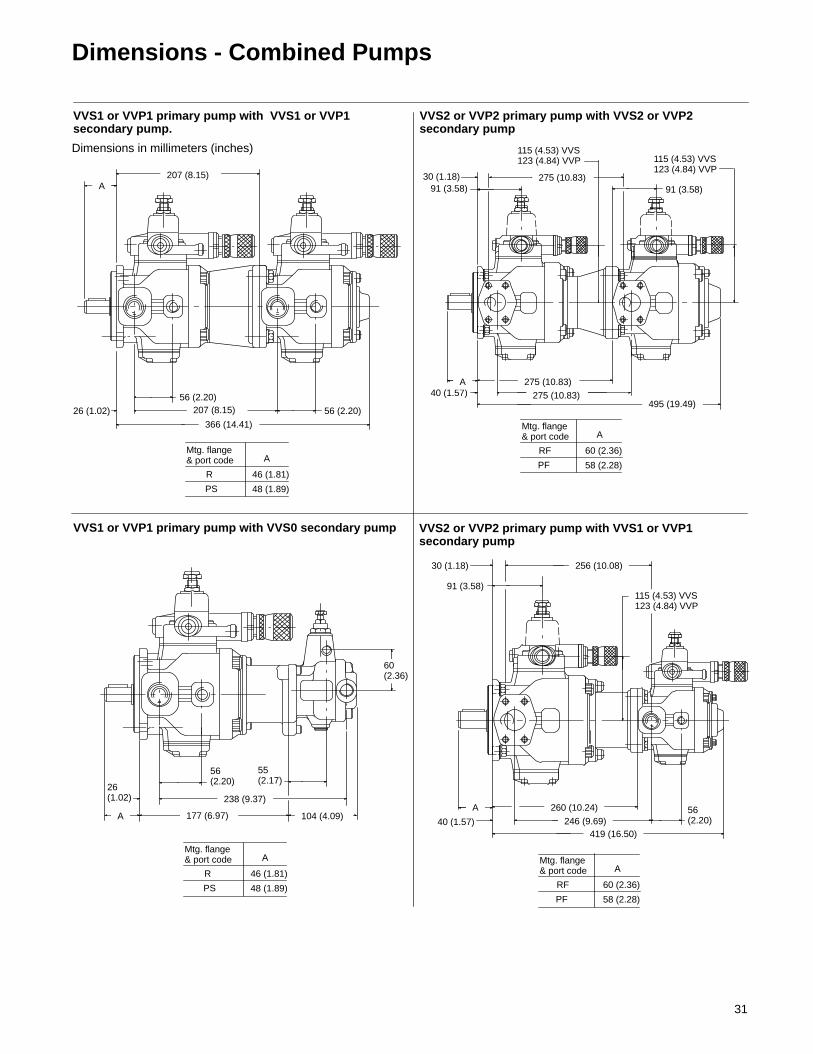
Dimensions - Combined Pumps
R
PS
46 (1.81)
40 (1.57)
26 (1.02)
26(1.02)
Dimensions in millimeters (inches)
177 (6.97) 104 (4.09)
238 (9.37)
56(2.20)
55(2.17)
60(2.36)
VVS1 or VVP1 primary pump with VVS0 secondary pump
VVS1 or VVP1 primary pump with VVS1 or VVP1secondary pump.
366 (14.41)
207 (8.15) 56 (2.20)
56 (2.20)
207 (8.15)
495 (19.49)275 (10.83)
275 (10.83)
275 (10.83)30 (1.18)91 (3.58) 91 (3.58)
VVS2 or VVP2 primary pump with VVS2 or VVP2secondary pump
VVS2 or VVP2 primary pump with VVS1 or VVP1secondary pump
40 (1.57)
115 (4.53) VVS123 (4.84) VVP
256 (10.08)30 (1.18)
91 (3.58)
56(2.20)
260 (10.24)
246 (9.69)419 (16.50)
115 (4.53) VVS123 (4.84) VVP
115 (4.53) VVS123 (4.84) VVP
Mtg. flange& port code A
48 (1.89)
A
RF
PF
60 (2.36)
A
58 (2.28)
A
AA
Mtg. flange& port code
R
PS
46 (1.81)
Mtg. flange& port code A
48 (1.89) RF
PF
60 (2.36)
A
58 (2.28)
Mtg. flange& port code

32
Dimensions - Combined Pumps
VVS2 or VVP2 primary pump with VVS0 secondary pump
Dimensions in millimeters (inches)
VVS3 or VVP3 primary pump with VVS3, VVP3, VVS2 orVVP2 secondary pump
VVS3 or VVP3 primary pump with VVS1 or VVP1secondary pump
VVS3 or VVP3 primary pump with VVS0 secondary pump
258 (10.16) 104 (4.09)
305 (12.01)40 (1.57)
315 (12.40)
30 (1.18)
55 (2.17)91 (3.58)
60(2.36)
46 (1.81) A
AB
C
D
E
36 (1.42)105 (4.13)
VVS3, VVP3
Secondarypump
315(12.40)
A
294(11.57)
105(4.13)
B
91(3.58)
125 (4.92) VVS3133 (5.24) VVP3
C
115 (4.53) VVS2123 (4.84) VVP2
315(12.40)
D
300(11.81)
560(22.05)
E
520(20.47)
VVS2, VVP2
275 (10.83)
46 (1.81) 265 (10.43)
36 (1.42)
105 (4.13)
56(2.20)
285 (11.22)A
444 (17.48)
283 (11.14)
334 (13.15)
324 (12.76)
60(2.36)
36 (1.42)
46 (1.81)
105 (4.13) 55 (2.17)
104 (4.09)
115 (4.53) VVS123 (4.84) VVP
125 (4.92) VVS133 (5.24) VVP
125 (4.92) VVS133 (5.24) VVP
125 (4.92) VVS133 (5.24) VVP
A
RF
PF
60 (2.36)
A
58 (2.28)
Mtg. flange& port code
RF
PF
68 (2.68)
A
58 (2.28)
Mtg. flange& port code
RF
PF
68 (2.68)
A
58 (2.28)
Mtg. flange& port code
A
F
RF
PF
68 (2.68)
F
58 (2.28)
Mtg. flange& port code

33
Key Lock Adjustment for VVP Pumps
133 (5.24)
123 (4.84)
82 (3.23)
“KL” control adjustmentfor VVP1, VVP2 and VVP3single pumps
“KL” control adjustmentfor VVP1, VVP2 and VVP3combined pumpsNOTE: Because of length, controlson combined pumps are mountedperpendicular to pump shaft
CETOP 03 controlmounted here82
(3.23)
C
B
A max
166 (6.54) max
Pressure setting knob.Turning clockwiseincreases pressure.
Pressure setting knob.Turning clockwiseincreases pressure.
VVP1
Pump
116 (4.57)
B
96 (3.78)
C
VVP2
B
C
VVP3
143 (5.63)
153 (6.02)
Pump A B C
VVP1 162 (6.38) 162 (6.38) 139 (5.47)
VVP2 155 (6.10) 189 (7.44) 166 (6.54)
VVP3 155 (6.10) 199 (7.83) 176 (6.93)

34
Dimensions - Mounting, Shaft and Port Options
Mountings and Shafts
Fr me
Mtg.flange
ISO mounting flange SAE mounting flange Front end shaft Rear end shaftFramesize
flange &portscode
Pilot dia. Bolt circledia.
Pilot dia. Bolt circledia.
Diameter Length Diameter Length
0R 80 (3.15) 103 (4.06) – – 20 (0.79) 36 (1.42) – –
0PS 80 (3.15) 103 (4.06) – 15,88 (0.625) 24 (0.938) – –
B – – – – 19 (0.75) 32 (1.26) – –
1 R 100 (3.94) 125 (4.92) – – 25 (0.98) 36 (1.42) 20 (0.79) 26 (1.02)
PS – – 101,6 (4.000) 127 (5.000) 25,4 (1.00) 38 (1.50) 20 (0.79) 26 (1.02)
B – – – – 25,37 (1.00) 50 (1.97) – –
2RF 125 (4.92) 160 (6.30) – – 32 (1.26) 50 (1.97) 28 (1.10) 45 (1.77)
2PF – – 127 (5.000) 181 (7.125) 31,75 (1.25) 48 (1.88) 28 (1.10) 45 (1.77)
PX 125 (4.92) 160 (6.30) – – 32 (1.26) 50 (1.97) 28 (1.10) 45 (1.77)
B – – – – 25,37 (1.00) 47 (1.85) – –
3RF 160 (6.30) 200 (7.87) – – 40 (1.57) 58 (2.28) 28 (1.10) 45 (1.77)
3PF – – 127 (5.000) 181 (7.125) 31,75 (1.25) 48 (1.88) 28 (1.10) 45 (1.77)
PX 160 (6.30) 200 (7.87) – – 40 (1.57) 58 (2.28) 28 (1.10) 45 (1.77)
Ports
Frame
Mtg.flange& Inlet port O tlet port
Drain portRemote pressurecontrol, loadsensing andFrame
size &portscode
Inlet port Outlet port
VVS pumps VVP pumps
sensing anddual-pressureload sensingports
0R G 1/2” BSP G 3/8” BSP G 1/4” BSP – –
0PS .875-14 UNF-2B .750-16 UNF-2B .500-20 UNF-2B – –
B 21 (0.83) 14 (0.55) 6 (0.24) 6 (0.24) –
1 R G 1” BSP G 3/4” BSP G 3/8” BSP G 3/8” BSP G 1/4” BSP
PS 1.3125-12 UNF-2B 1.0625-12 UNF-2B .5625-18 UNF-2B .5625-18 UNF-2B .500-20 UNF-2B
B 32 (1.26) 24 (0.94) 10 (0.39) 10 (0.39) –
2RF
1.50 SAE 4-blt.flange with M12 x 45deep mounting holes
1.00 SAE 4-blt.flange with M10 x 35deep mounting holes
G 1/2” BSP G 3/4” BSP G 1/4” BSP
PF 1.50 SAE 4-blt. flg.w/ 500 UNC x 1 75
1.00 SAE 4-blt. flg.w/ 4375 UNC x 1 50 875-14 UNF-2B 1 0625-12 UNF-2B 500-20 UNF-2B
PXw/ .500 UNC x 1.75deep mounting holes
w/ .4375 UNC x 1.50deep mounting holes
.875-14 UNF-2B 1.0625-12 UNF-2B .500-20 UNF-2B
B 35 (1.38) 28 (1.10) 13 (0.51) 13 (0.51) –
3RF
2.00 SAE 4-blt.flange with M12 x 45deep mounting holes
1.25 SAE 4-blt.flange with M10 x 40deep mounting holes
G 1/2” BSP G 3/4” BSP G 1/4” BSP
PF 2.00 SAE 4-blt. flg.w/ 500 UNC x 1 75
1.25 SAE 4-blt. flg.w/ 4375 UNC x 1 75 875-14 UNF-2B 1 0625-12 UNF-2B 500-20 UNF-2B
PXw/ .500 UNC x 1.75deep mounting holes
w/ .4375 UNC x 1.75deep mounting holes
.875-14 UNF-2B 1.0625-12 UNF-2B .500-20 UNF-2B

35
Installation Instructions
The following notes will assist in thecorrect installation of your pumps. 1. Pump frame sizes 0 & 1 can bemounted in any position. Pump sizes 2& 3 must be mounted with the shafthorizontal. In all cases, thecasing/compensator drain connectionmust be at the highest possible position.In applications where high flow ratesand pressures are required, it isrecommended that pumps be installedbelow the reservoir oil level, external ofthe reservoir. 2. The oil reservoir should have acapacity of at least 3–4 times the pumpflow rate per minute. In case ofcontinuous operation at high pressureand flow rate, it is advisable to use heatexchangers. In any case, oiltemperature should never exceed 60�C(140�F). Pumps are designed to operateat optimum working temperatures of 40to 50�C (104 to 122�F).
3. The inlet line should never bereduced from the port size. Excessiverestrictions and length will degradepump performance. 4. The drain line should be separate anddirectly piped to the reservoir andterminated below the minimum oil level,as far as possible from the pump inlet. 5. When operating pumps usingphosphate ester or water-oil emulsion,contact Vickers regarding maximumoperating pressure.

36
Form No. 00-000 Copyright Eaton Corporation, 0000All rights reserved.Printed in U.S.A
Eaton Hydraulics15151 Highway 5Eden Prairie, MN 55344Telephone: 612 937-7254Fax: 612 937-7130www.eatonhydraulics.com
46 New Lane, HavantHampshire PO9 2NBEnglandTelephone: (44) 170-548-6451Fax: (44) 170-548-7110