
VIBRATION CHARACTERISTICS ANALYSIS OF THE …€¦ · rub-impact rotors with mass ... of the next...
13
Mathematical and Computational Applications, Vol. 18, No. 2, pp. 71-83, 2013 VIBRATION CHARACTERISTICS ANALYSIS OF THE RUB- IMPACT ROTOR SYSTEM WITH MASS UNBALANCE Jiu-Hong Jia and Tian-Qi Hang Key Laboratory of Pressure Systems and Safety, Ministry of Education East China University of Science and Technology, 200237 Shanghai, PR China [email protected] Abstract- In this paper, vibration characteristics of a rub-impact Jeffcott rotor system excited by mass unbalance including the eccentric mass and the initial permanent deflection are investigated. Through the numerical calculation, rotating speeds, mass eccentricities, initial permanent deflections and phase angles between the eccentric mass direction and the rotor initial permanent deflection direction are used as control parameters to investigate their effect on the rub-impact rotor system with the help of bifurcation diagrams, Poincare maps, frequency spectrums and orbit maps. Result shows that these two kinds of mass unbalance have great but different effect on the dynamic characteristic of the rubbing rotor system. Different motion characteristics appear with the varying of these control parameters, and complicated motions such as periodic and quasi-periodic vibrations are observed. Corresponding results can be used to diagnose the rub-impact fault and decrease the effect of rub impact in the rotor system with mass unbalance. Key Words- Rub-impact rotor system, Mass unbalance, Nonlinear motion 1. INTRODUCTION Mass unbalance of the rotor is the main factor to increase vibration and bring unstable characteristics to the whole rotor system [1-2]. Since the rotor-stator rub is one of the main faults for large rotary machines, it has attracted great concern and lots of research work has been done by many researchers. Cao and Ma [3] investigated nonlinear dynamic characteristics of rub-impact rotor system with fractional order damping. From the study, various complicated dynamic behaviors and types of routes to chaos were found, including period doubling bifurcation, sudden transition and quasi- periodic from periodic motion to chaos. Jawaidi [4] investigated dynamics of a rigid rotor supported by load-sharing between magnetic and auxiliary bearings for a range of realistic design and operating parameters. Many phenomena were found and studied. Zhang and Meng [5] carried out an analytical investigation on the stability of the rub
Transcript of VIBRATION CHARACTERISTICS ANALYSIS OF THE …€¦ · rub-impact rotors with mass ... of the next...

Mathematical and Computational Applications, Vol. 18, No. 2, pp. 71-83, 2013
VIBRATION CHARACTERISTICS ANALYSIS OF THE RUB- IMPACT
ROTOR SYSTEM WITH MASS UNBALANCE
Jiu-Hong Jia and Tian-Qi Hang
Key Laboratory of Pressure Systems and Safety, Ministry of Education
East China University of Science and Technology, 200237
Shanghai, PR China
Abstract- In this paper, vibration characteristics of a rub-impact Jeffcott rotor system
excited by mass unbalance including the eccentric mass and the initial permanent
deflection are investigated. Through the numerical calculation, rotating speeds, mass
eccentricities, initial permanent deflections and phase angles between the eccentric mass
direction and the rotor initial permanent deflection direction are used as control
parameters to investigate their effect on the rub-impact rotor system with the help of
bifurcation diagrams, Poincare maps, frequency spectrums and orbit maps. Result
shows that these two kinds of mass unbalance have great but different effect on the
dynamic characteristic of the rubbing rotor system. Different motion characteristics
appear with the varying of these control parameters, and complicated motions such as
periodic and quasi-periodic vibrations are observed. Corresponding results can be used
to diagnose the rub-impact fault and decrease the effect of rub impact in the rotor
system with mass unbalance.
Key Words- Rub-impact rotor system, Mass unbalance, Nonlinear motion
1. INTRODUCTION
Mass unbalance of the rotor is the main factor to increase vibration and bring
unstable characteristics to the whole rotor system [1-2]. Since the rotor-stator rub is one
of the main faults for large rotary machines, it has attracted great concern and lots of
research work has been done by many researchers. Cao and Ma [3] investigated
nonlinear dynamic characteristics of rub-impact rotor system with fractional order
damping. From the study, various complicated dynamic behaviors and types of routes to
chaos were found, including period doubling bifurcation, sudden transition and quasi-
periodic from periodic motion to chaos. Jawaidi [4] investigated dynamics of a rigid
rotor supported by load-sharing between magnetic and auxiliary bearings for a range of
realistic design and operating parameters. Many phenomena were found and studied.
Zhang and Meng [5] carried out an analytical investigation on the stability of the rub

72 J.H. Jia and T.Q. Hang
solutions of the rotor system in MEMS. Numerical calculation demonstrated the
complex nonlinear motion forms in this system.
Although much work has been done respectively on the research of rotor mass
unbalance and rotor-stator rubbing impact, the vibration characteristics of this kind of
rub-impact rotors with mass unbalance have rarely been studied specially in the
literature. Due to mass unbalance’s ubiquity, great effect on the vibration of the rub-
impact rotor system and rub’s large threat to the safe operation of the rotor system,
Therefore, in this paper attention is paid to the research of vibration characteristics of
rub-impact rotors with mass unbalance.
2. PHYSICAL MODEL AND EUATIONS
Rub-impact forces in the O-xy coordinate system are [6]:
cos sin (1 h ) ( )
sin cos (1 h ) ( )
x N T r
y N T r
F F F r K x y
F F F r K x y
(1)
when r h , the rub doesn’t happen. When r h , the rub happens. Carrying out
the nondimensional procedure, the governing motion equations are as follows:
When ˆ 1.0R r h , the rub doesn’t happen, and the nondimensional motion
equations are:
2
0 0
2
0 0
ˆ ˆ ˆ ˆ'' 2 ' cos cos( )
ˆ ˆ ˆ ˆ'' 2 ' sin sin( )
x x x T r T
y y y T r T
(2)
When ˆ 1.0R r h , the rub happens, and the nondimensional motion equations
are:
2
0 0
2
0 0
ˆ ˆˆ ˆ ˆ ˆ ˆ ˆ'' 2 ' (1 1 )( ) cos cos( )
ˆ ˆˆ ˆ ˆ ˆ ˆ ˆ'' 2 ' (1 1 )( ) sin sin( )
x x x K R x y T r T
y y y K R x y T r T
(3)
Where: x x h , y y h , ˆrK K K ,
02C M , 0 K M the natural frequency of
the shaft, 0 the frequency ratio,
me h , 0 0r r h ,
0T t , ' d dT .
Since the nondimensional governing equations of motion have been got above,
they are transferred into a set of first order differential equations ( )u f u . Then the
fourth-order Runge-Kutta method is used to integrate this set of equations. According to
the analysis need, some parameters can be used as the control parameters such as the
rotor rotating speed, the initial permanent deflection and so on, while other parameters
keep fixed during every time of calculation. To get the stable result, a small integration

Rub-Impact Rotor System with Mass Unbalance 73
step has to be chosen to avoid the numerical divergence at the point where derivatives
of xF and
yF are discontinuous. In this paper, the integration step is chosen to be
2 /500 , i.e., within one period, there are 500 times of integral calculation. Generally,
long time marching computation is required to obtain a convergent orbit. In this paper,
during every calculation, results of the first 500 periods are abandoned, and then results
of the next 100 periods are got to carry out various kinds of analysis. To study the
vibration characteristics of the rubbing rotor system with mass unbalance, bifurcation
diagrams, Poincare maps, frequency spectrums and orbit maps are employed. They are
all useful and effective ways to illustrate the motion behavior of the rotor system.
3. NUMERICAL SIMULATION OF MOTIONS OF THE ROTOR SYSTEM
3.1. Effect of Rotor Rotating Speeds
Although many parameters such as the system damping and the frictional
coefficient between the rotor and the stator can be used to investigate the vibration
characteristics of the rub-impact system, the most common and useful parameter used is
the rotor rotating speed. The whole starting process can be observed by using the
rotating speed to simulate the rub-impact rotor system. The parameters used during
computations are: =0.12, K =30.0, 0.12 .
0 0.5 1 1.5 2 2.5 3-0.6
-0.4
-0.2
0
0.2
0.4
Rotating speed ratio
X
(a) =0.2
0 0.5 1 1.5 2 2.5 3
-0.2
0
0.2
0.4
0.6
0.8
1
1.2
Rotating speed ratio
X
(b)
0r =0.8,0 / 4 ;

74 J.H. Jia and T.Q. Hang
0 0.5 1 1.5 2 2.5 3-0.5
0
0.5
1
1.5
Rotating speed ratio
X
(c)
0r =0.8,0 / 4 , =0.2
Figure 1. Bifurcation diagram
Fig.1.(a) is the bifurcation diagram of the rub-impact rotor’s vibration which is
excited only by the eccentric mass. Fig.1.(b) is the bifurcation diagram of the rub-
impact rotor’s vibration which is excited only by the initial permanent deflection.
Fig.1.(c) is the bifurcation diagram of the vibration excited by these two kinds of mass
unbalance jointly. Very clearly from Fig.1, different shapes of three diagrams
demonstrate that the eccentric mass and the initial permanent deflection have different
influence to the vibration of the rubbing rotor system and both contribute a lot to the
vibration characteristics of the rub-impact rotor system. As shown in Fig.1.(a), the rub-
impact motion excited only by the eccentric mass keeps synchronous with period-one
for the whole calculating rotating speed range. Fig.2 shows that only one point is
correspondingly shown in the Poincare map, only one peak appears in the frequency
spectrum, and the orbit of the rotor center is an ellipse. All these further demonstrate the
motion is period-one motion. From Fig.1.(b), it can be seen that when the rotating speed
ratio is from 0.0 to 1.1, the motion is period-one. From 1.1 to 1.6, the motion is quasi-
periodic, then the motion transits to period-one motion again for the higher speed ratios.
This can be seen from Fig.3. It illustrates the rubbing motion excited only by the initial
permanent deflection at =1.2. The Poincare map is a closed circle, several peaks
appear in the frequency spectrum, and the rotor center orbit is irregular. These prove
that the motion is quasi-periodic.
From Fig.1.(c), it can be seen that when the rotating speed ratio is from 0.0 to 1.1,
the motion is period-one, from 1.1 to 2.4, the motion is quasi-periodic, then the motion
transits to period-one motion again for the higher speed ratios. This motion type is
clearly different from the one excited only by the eccentric mass in Fig.1.(a) and the one
excited only by the initial permanent deflection in Fig.1.(b). Fig.4 demonstrates that the
motion in this case at =1.5 is quasi-periodic as analyzed above.

Rub-Impact Rotor System with Mass Unbalance 75
-1.5 -1 -0.5 0 0.5 1-1
-0.5
0
0.5
1
1.5
X
X`
(a) Poincare map
-0.4 -0.2 0 0.2 0.4-0.4
-0.3
-0.2
-0.1
0
0.1
0.2
0.3
0.4
X
Y
(b) orbit
0 1 2 3 4 50
0.05
0.1
0.15
0.2
0.25
0.3
0.35
0.4
Frequency
X
(c) spectrum of frequency
Figure 2. Motion excited by =0.2 at =1.5
0.9 0.95 1 1.05 1.1-0.8
-0.6
-0.4
-0.2
0
0.2
X
X`
(a) Poincare map
-1.5 -1 -0.5 0 0.5 1 1.5-1.5
-1
-0.5
0
0.5
1
1.5
X
Y
(b) orbit

76 J.H. Jia and T.Q. Hang
0 2 4 6 80
0.2
0.4
0.6
0.8
1
Frequency
X
(c) spectrum of frequency
Figure 3. Motion excited by 0r =0.8,
0 / 4 at =1.2
0.4 0.6 0.8 1 1.2 1.4-1.5
-1
-0.5
0
0.5
1
1.5
X
X`
(a) Poincare map
-1.5 -1 -0.5 0 0.5 1 1.5-1.5
-1
-0.5
0
0.5
1
1.5
X
Y
(b) orbit
0 1 2 3 4 50
0.1
0.2
0.3
0.4
0.5
0.6
0.7
0.8
Frequency
X
(c) spectrum of frequency
Figure 4. Motion excited jointly by and 0r at =1.5

Rub-Impact Rotor System with Mass Unbalance 77
3.2. Effect of the Eccentric Mass
Eccentric mass is one of the mass unbalance to excite the motion of the rotor
system, so it’s essential to study its effect on dynamic characteristic of the rub-impact
rotor system. Fig.3 are bifurcation diagrams of rotor’s vibration at different rotating
speeds using the mass eccentricity ratio as the control parameter. The initial
permanent deflection is not included in this analysis and is set as 0.0.
0.05 0.1 0.15 0.2 0.25 0.3 0.350
0.1
0.2
0.3
0.4
0.5
0.6
0.7
0.8
Mass eccentricity ratio
X
(a) =1.0
0.05 0.1 0.15 0.2 0.25 0.3 0.35-0.5
-0.2
0.1
0.4
0.7
1
Mass eccentricity ratio
X
(b) =1.5
Figure 5. Bifurcation diagram using as the control parameter
-0.5 0 0.5 1 1.5 2-0.5
0
0.5
1
1.5
2
X
X`
(a) Poincare map
-1.5 -1 -0.5 0 0.5 1 1.5-1.5
-1
-0.5
0
0.5
1
1.5
X
Y
(b) orbit

78 J.H. Jia and T.Q. Hang
0 1 2 3 4 50
0.2
0.4
0.6
0.8
1
Frequency
X
(c) spectrum of frequency
Figure 6. Motion with =0.3 at =1.0
0.4 0.5 0.6 0.7 0.8
0.4
0.6
0.8
1
1.2
1.4
1.6
1.8
2
X
X`
(a) Poincare map
-1.5 -1 -0.5 0 0.5 1 1.5-1.5
-1
-0.5
0
0.5
1
1.5
X
Y
(b) orbit

Rub-Impact Rotor System with Mass Unbalance 79
0 1 2 3 4 50
0.2
0.4
0.6
0.8
1
Frequency
X
(c) spectrum of frequency
Figure 7. Motion with =0.3 at =1.5
As shown in Fig.5.(a), when the rotating speed ratio is not high like 1.0, the motion
of the rub-impact rotor system keeps synchronous with period-one for the whole
calculating range. Further demonstration is shown in Fig.6 with =0.3 at =1.0 that
only one point is correspondingly shown in the Poincare map, only one peak appears in
the frequency spectrum, and the orbit of the rotor center is an ellipse. All these further
demonstrate the motion is period-one motion.
As shown in Fig.5. (b), at =1.5 when the mass eccentricity ratio is from 0.0 to
0.26, the motion is period-one. From 0.26 to higher values of the mass eccentricity ratio,
the motion keeps quasi-periodic. In Fig.7 with =0.3 at =1.5, the Poincare map is a
closed circle, several peaks appear in the frequency spectrum, and the rotor center orbit
is irregular. These prove that the motion is quasi-periodic.
3.3. Effect of the Initial Permanent Deflection
The initial permanent deflection is another one of the mass unbalance to excite the
motion of the rotor system, it’s also important to study its effect on dynamic
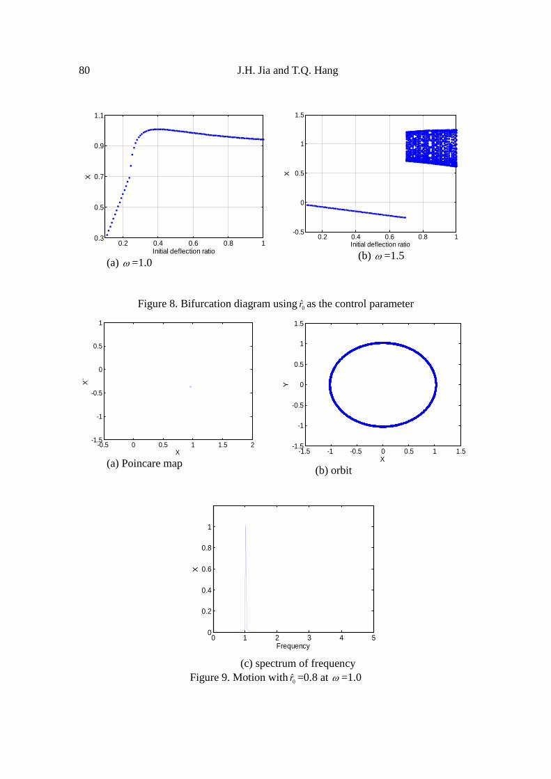
characteristic of the rub-impact rotor system. Fig.8 is bifurcation diagrams of rotor’s
vibration at different rotating speeds using the initial permanent deflection ratio 0r as
the control parameter. The mass eccentricity is not included in this analysis and is set as
0.0. 0 is fixed as / 4 .
80 J.H. Jia and T.Q. Hang
0.2 0.4 0.6 0.8 10.3
0.5
0.7
0.9
1.1
Initial deflection ratio
X
(a) =1.0
0.2 0.4 0.6 0.8 1-0.5
0
0.5
1
1.5
Initial deflection ratio
X
(b) =1.5
Figure 8. Bifurcation diagram using0r as the control parameter
-0.5 0 0.5 1 1.5 2-1.5
-1
-0.5
0
0.5
1
X
X`
(a) Poincare map
-1.5 -1 -0.5 0 0.5 1 1.5-1.5
-1
-0.5
0
0.5
1
1.5
X
Y
(b) orbit
0 1 2 3 4 50
0.2
0.4
0.6
0.8
1
Frequency
X
(c) spectrum of frequency
Figure 9. Motion with0r =0.8 at =1.0

Rub-Impact Rotor System with Mass Unbalance 81
0.7 0.8 0.9 1 1.1 1.2 1.3
-1
-0.5
0
0.5
1
X
X`
(a) Poincare map
-1.5 -1 -0.5 0 0.5 1 1.5-1.5
-1
-0.5
0
0.5
1
1.5
X
Y
(b) orbit
0 1 2 3 4 50
0.2
0.4
0.6
0.8
1
Frequency
X
(c) spectrum of frequency
Figure 10. Motion with0r =0.8 at =1.5
As shown in Fig.8.(a), when the rotating speed ratio is at 1.0, the motion of the
rub-impact rotor system keeps synchronous with period-one for the initial deflection
ratio ranging from 0.0 to 1.0. Further demonstration is shown in Fig.9 with 0r =0.8 at
=1.0.
As shown in Fig.7.(b), at =1.5 when the initial permanent deflection ratio 0r is
from 0.0 to 0.7, the motion is period-one. From 0.7 to higher values of the initial
permanent deflection ratio, the motion keeps quasi-periodic. Further demonstration is
shown in Fig.10 with 0r =0.8 at =1.5.
3.4. Effect of Phase Angles between the Eccentric Mass Direction and the Rotor
Deflection Direction
As shown in above equations (2) and (3), the phase angle between the eccentric
mass direction and the rotor deflection direction is an important factor to influence the
82 J.H. Jia and T.Q. Hang
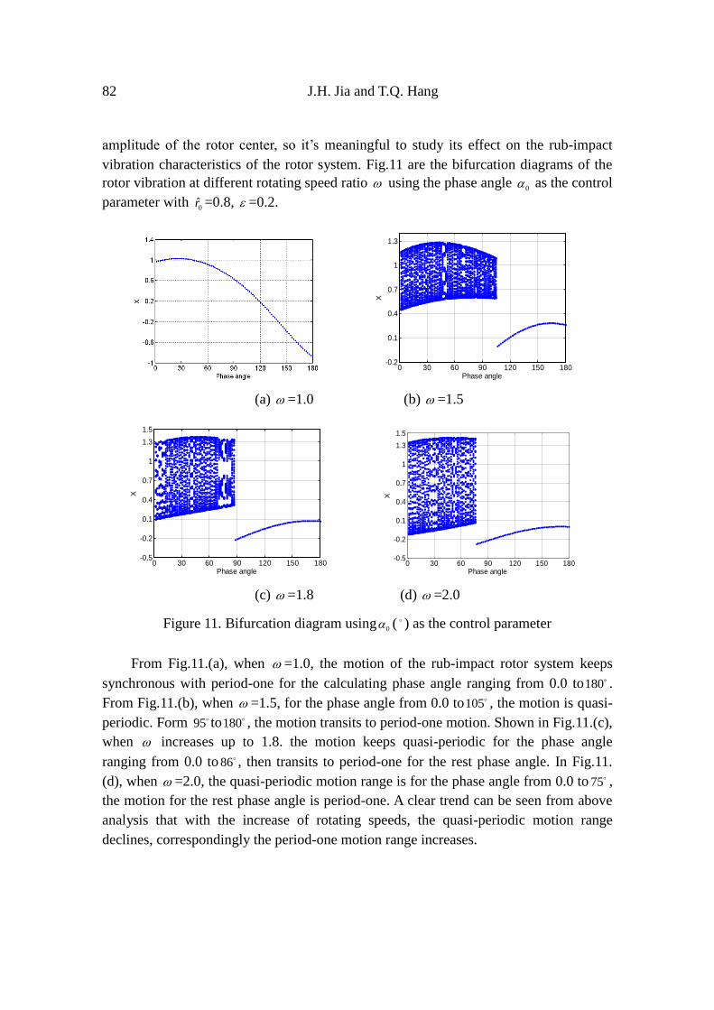
amplitude of the rotor center, so it’s meaningful to study its effect on the rub-impact
vibration characteristics of the rotor system. Fig.11 are the bifurcation diagrams of the
rotor vibration at different rotating speed ratio using the phase angle 0 as the control
parameter with 0r =0.8, =0.2.
0 30 60 90 120 150 180
-0.2
0.1
0.4
0.7
1
1.3
Phase angleX
(a) =1.0 (b) =1.5
0 30 60 90 120 150 180-0.5
-0.2
0.1
0.4
0.7
1
1.3
1.5
Phase angle
X
0 30 60 90 120 150 180
-0.5
-0.2
0.1
0.4
0.7
1
1.3
1.5
Phase angle
X
(c) =1.8 (d) =2.0
Figure 11. Bifurcation diagram using0 ( ) as the control parameter
From Fig.11.(a), when =1.0, the motion of the rub-impact rotor system keeps
synchronous with period-one for the calculating phase angle ranging from 0.0 to180 .
From Fig.11.(b), when =1.5, for the phase angle from 0.0 to105 , the motion is quasi-
periodic. Form 95 to180 , the motion transits to period-one motion. Shown in Fig.11.(c),
when increases up to 1.8. the motion keeps quasi-periodic for the phase angle
ranging from 0.0 to 86 , then transits to period-one for the rest phase angle. In Fig.11.
(d), when =2.0, the quasi-periodic motion range is for the phase angle from 0.0 to 75 ,
the motion for the rest phase angle is period-one. A clear trend can be seen from above
analysis that with the increase of rotating speeds, the quasi-periodic motion range
declines, correspondingly the period-one motion range increases.

Rub-Impact Rotor System with Mass Unbalance 83
4. CONCLUSIONS
In this paper, vibration characteristics of a rub-impact Jeffcott rotor system excited
by mass unbalance including the eccentric mass and the initial permanent deflection are
investigated. From numerical calculation, rotating speeds, mass eccentricities, initial
permanent deflections and phase angles between the eccentric mass direction and rotor
initial permanent deflection direction are used as the control parameters to investigate
their effect on the rub-impact rotor system. Result shows that these two kinds of mass
unbalance: eccentric mass and initial permanent deflection have great but different
effect on the dynamic characteristic of the rubbing rotor system. Periodic, quasi-
periodic motions appear with the varying of these control parameters. Because the
quasi-periodic motion is the route to chaos, it indicates that the system has the potential
to become chaotic. These results can be used to diagnose the rub fault and direct the
work to decrease the effect of rub impact in the rotor system with mass unbalance.
Acknowledgements- The authors are grateful for the support of National natural
science foundation of China (NO.50905059) and new teacher fund of doctorial program
sponsored by Ministry of Education of China (20090074120005).
5. REFERENCES
1. Y. H. Liao, and P. Zhang, Unbalance related rotor precession behavior analysis and
modification to the holobalancing method. Mechanism and Machine Theory 45, 601-
610. 2010.
2. A. K. Jalan and A.R. Mohanty, Model based fault diagnosis of a rotor–bearing system
for misalignment and unbalance under steady-state condition. Journal of Sound and
Vibration 327, 604-622, 2009.
3. J. Y. Cao, C. B. Ma, etc. Nonlinear dynamic analysis of fractional order rub-impact
rotor system. Communications in Nonlinear Science and Numerical Simulation 16,
1443-1463, 2011.
4. I. H. Jawaidi, Nonlinear dynamics of a magnetically supported rigid rotor in auxiliary
bearings. Mechanism and Machine Theory 45, 1651-1667, 2010.
5. W. M. Zhang and G. Meng. Stability, bifurcation and chaos of a high-speed rub-
impact rotor system in MEMS. Sensors and Actuators A 127, 163-178, 2006.
6. X. Y. Shen, J. H. Jia and M. Zhao, Nonlinear analysis of a rub-impact rotor-bearing
system with initial permanent rotor bow, Archive of Applied Mechanics 78, 225-240,
2008.


![Vibration Signature Analysis of 4 Jaw Flexible Coupling ... · PDF file[15] did experimental vibration analysis of rotors for the identification of shaft misalignment. In this paper](https://static.fdocuments.in/doc/165x107/5a78b78b7f8b9a83238b69df/vibration-signature-analysis-of-4-jaw-flexible-coupling-15-did-experimental.jpg)


