Modal Testing of Rotors with Fluid...
35
International Journal of Rotating Machinery 1995, Vol. l, No. 2, pp. 83-116 Reprints available directly from the publisher Photocopying permitted by license only (C) 1995 OPA (Overseas Publishers Association) Amsterdam B.V. Published under license by Gordon and Breach Science Publishers SA Printed in the United States of America Modal Testing of Rotors with Fluid Interaction AGNES MUSZYNSKA Bently Rotor Dynamics Research Corporation, Minden, NV 89423 Modal testing of rotating structures has specific aspects, and it requires a specialized approach. Classical modal testing when applied to active (rotating) structures does not provide complete results. These aspects, and specific application of sweep frequency circular input force perturbation testing of rotors rotating in fluid environment, are discussed in this paper. Emphasis is placed on nonsynchronous perturbation of shafts rotating at a constant rotative speed. The results are presented in the direct and quadrature dynamic stiffness versus perturbation frequency formats, which permits the separation of components for easy evaluation. This perturbation technique provided new results: 1) identification of solid/fluid interaction modes; 2) identification of fluid dynamic forces in lightly loaded bearings and seals; and 3) multimode identification of rotor systems. Results of several laboratory rig experiments, the identification algorithm, and data processing techniques are discussed. A comparison with other testing methods is given. Key Words: Modal testing; rotor systems; dynamic stiffness, parameter identification;fluid interaction modes XPERIMENTAL modal analysis has become a pop- ular method for studying practical vibration prob- lems of mechanical structures. Application of modal test- ing for parameter identification of rotating machines, which represent an important class of mechanical struc- tures, has several specific aspects and requires a special- ized approach. The results and predictions obtained by applying the classical "passive structure" modal testing to a rotating machine are usually incomplete, and not suf- ficiently accurate for the most important lateral modes, while providing information not significant for the rotat- ing machine operating performance. SPECIFIC ASPECTS OF MODAL TESTING OF ROTATING MACHINES Most of the modal identification methods and conven- tional procedures of modal analysis deal with structures with assumed linear behavior. The structures are modeled by self-adjoint differential operators, and discretized by symmetric matrices. Rotating machines have an inherent nonsymmetric nature, due to rotation-related factors, such as gyroscopic effects, and fluid dynamic forces in bear- ings and seals, which provide feedback-like effects. The dynamic behavior of rotating machines can adequately be represented only by the nonself-adjoint differential oper- ators. The discretization yields nonsymmetric matrices. The modal analysis must not only determine all classical modal parameters (for example, eigenvalues, eigenfunc- tions constituting the right eigenvectors and form of eigen- functions yielding generalized/modal masses associated with each eigenmode), but also the parameters provided by the left eigenfunctions. Decoupling of rotor precessional mode components requires the utilization of additional relations (such as biorthogonality) between left and right eigenvectors (Childs 1976], Glasgow et al. 1980], Bigret [1984], Andrews [1985], Zhang et al. [1985]). Rotating machines can be modeled by linear equations in very limited ranges of deflections and velocities. The classical modal analysis, based on the assumption of lin- earity, has to be completed by taking nonlinearities into consideration. Significant nonlinear effects of geometric and physical origin in rotating machines can introduce large errors on the classical modal tests (Black et al. [1980], Fillod et al. [1985], Sullivan [1985]). All dynamic phenomena occurring during the perfor- mance of a rotating machine are closely related to the ro- tative motion of the rotor (Fig. 1). The continuous supply
Transcript of Modal Testing of Rotors with Fluid...

International Journal ofRotating Machinery1995, Vol. l, No. 2, pp. 83-116Reprints available directly from the publisherPhotocopying permitted by license only
(C) 1995 OPA (Overseas Publishers Association) Amsterdam B.V.Published under license by Gordon and Breach Science Publishers SA
Printed in the United States of America
Modal Testing of Rotors with Fluid Interaction
AGNES MUSZYNSKABently Rotor Dynamics Research Corporation, Minden, NV 89423
Modal testing of rotating structures has specific aspects, and it requires a specialized approach. Classical modal testing whenapplied to active (rotating) structures does not provide complete results. These aspects, and specific application of sweepfrequency circular input force perturbation testing of rotors rotating in fluid environment, are discussed in this paper.
Emphasis is placed on nonsynchronous perturbation ofshafts rotating at aconstant rotative speed. The results are presented inthe direct and quadrature dynamic stiffness versus perturbation frequency formats, which permits the separation ofcomponentsfor easy evaluation. This perturbation technique provided new results: 1) identification of solid/fluid interaction modes;2) identification of fluid dynamic forces in lightly loaded bearings and seals; and 3) multimode identification ofrotor systems.Results of several laboratory rig experiments, the identification algorithm, and data processing techniques are discussed. Acomparison with other testing methods is given.
Key Words: Modal testing; rotorsystems; dynamic stiffness, parameter identification;fluid interactionmodes
XPERIMENTAL modal analysis has become a pop-ular method for studying practical vibration prob-
lems of mechanical structures. Application of modal test-ing for parameter identification of rotating machines,which represent an important class of mechanical struc-tures, has several specific aspects and requires a special-ized approach. The results and predictions obtained byapplying the classical "passive structure" modal testing toa rotating machine are usually incomplete, and not suf-ficiently accurate for the most important lateral modes,while providing information not significant for the rotat-ing machine operating performance.
SPECIFIC ASPECTS OF MODALTESTING OF ROTATING MACHINES
Most of the modal identification methods and conven-tional procedures of modal analysis deal with structureswith assumed linear behavior. The structures are modeledby self-adjoint differential operators, and discretized bysymmetric matrices. Rotating machines have an inherentnonsymmetric nature, due to rotation-related factors, suchas gyroscopic effects, and fluid dynamic forces in bear-
ings and seals, which provide feedback-like effects. Thedynamic behavior of rotating machines can adequately berepresented only by the nonself-adjoint differential oper-ators. The discretization yields nonsymmetric matrices.The modal analysis must not only determine all classicalmodal parameters (for example, eigenvalues, eigenfunc-tions constituting the right eigenvectors and form ofeigen-functions yielding generalized/modal masses associatedwith each eigenmode), but also the parameters provided bythe left eigenfunctions. Decoupling of rotor precessionalmode components requires the utilization of additionalrelations (such as biorthogonality) between left and righteigenvectors (Childs 1976], Glasgow et al. 1980], Bigret[1984], Andrews [1985], Zhang et al. [1985]).
Rotating machines can be modeled by linear equationsin very limited ranges of deflections and velocities. Theclassical modal analysis, based on the assumption of lin-earity, has to be completed by taking nonlinearities intoconsideration. Significant nonlinear effects of geometricand physical origin in rotating machines can introducelarge errors on the classical modal tests (Black et al.[1980], Fillod et al. [1985], Sullivan [1985]).
All dynamic phenomena occurring during the perfor-mance of a rotating machine are closely related to the ro-tative motion of the rotor (Fig. 1). The continuous supply
84 A. MUSZYNSKA
INPUT
(e. g., FORCE)
ROTATIVE ENERGY$ROTATING MACHINE
OPERATIONAL TEMPERATUREPRESSURE, LOAD, ETC.
OUTPUT
(e.g., VIBRATION)
FIGURE Perturbation technique for modal testing of rotating ma-chines at their operational conditions.
of rotative energy makes the system "active," containing afeedback loop. Numerous vibrational phenomena in rotat-ing machines occur due to the transfer of energy from ro-tation (main performance) to vibration (undesirable sideeffects). Rotation of the shaft with all mechanical partsattached to it, as well as involvement in rotation of theworking fluid (in fluid-flow machines, in seals, and in bear-ings), causes important modifications in modes and naturalfrequencies. In large turbomachines, additional changescan be generated by thermal effects, foundation deforma-tions, and misalignment. All these factors cause the resultsof modal testing of rotating machines "at rest" ("passivestructure" approach) to differ significantly from the resultsof testing during machine operational conditions ("activestructure" approach).
Rotors, which represent the main parts of rotating ma-chines, are similarly constrained in two lateral directions;therefore, they exhibit vibrational motion which alwayshas two inseparably coupled, two-orthogonal lateral com-ponents (conventionally called "vertical" and "horizon-tal"). The lateral vibrations result in two-dimensional pre-cessional motion of the rotor. Widely used unidirectionalimpulse testing, when applied to a rotating shaft, results ina response containing vertical and horizontal components,and an undetermined tangential input force components.
In practical performances of rotors, the precessionalmotion can contain multi-frequency, two-dimensionalcomponents, with definite relations to the direction of ro-tation. In the most general case, each individual compo-nent can be either forward (direction of precession thesame as direction of rotation) or backward (direction ofprecession opposite to rotation). The direction of preces-sional motion is vital to the rotor integrity, as it deter-mines the rotor stress/deformation pattern. The net defor-mation frequency of the rotor is equal to the differencebetween rotative and precessional frequencies, with theirsigns taken into account. During backward precession theshaft is therefore subject to high frequency deformation(sum of both frequencies). When measuring rotating ma-
chine vibrations, it is important to identify each vibrationalfrequency component, whether it is forward or backward.Narrow band filtering, and time base/orbit analysis, areextremely helpful for this purpose. In classical modal test-ing, "negative" frequencies have no meaning. Applied torotating machines, the "negative" frequency has a direct,and very significant physical interpretation related to rotorbackward precession.Most important vibrational phenomena of rotating ma-
chines are associated with rotor lateral vibrations. Eachmode of rotor lateral vibration contains two components(vertical and horizontal), the characteristics of which are,usually, slightly different as a result ofelasticity/mass non-symmetry of the rotor, and supporting structure, in twoorthogonal lateral directions. Modal testing of structureswith closely spaced modes presents numerous difficulties.Rotating machines belong to this category. An alleviationofthe problem is offered by consideration of "pair modes"in rotating machines (for example, "first mode vertical"and "first mode horizontal").
Classical modal testing usually, though not always,deals with a large number of modes of a structure overa broad frequency range. In the performance of rotatingmachines, the most important are the lowest modes, andlow-frequency precessional phenomena. This is because:first, the stiffness/mass characteristics of a rotor are al-ways located in a lower range of frequencies than those ofthe supporting structure. The lowest modes of the rotatingmachine correspond, therefore, to the modes of the rotoritself. Second, the rotating machine has its own continu-ously active forcing function--the unbalance, which is aninseparable feature of the rotating system. The frequencyof this force is equal to the rotor’s actual rotative speed.The resulting motion is referred to as a "synchronous"precession. The operating speed of a single-span machinetrain, even if it represents dozens of thousands of rpm, sel-dom exceeds the third balance resonance frequency (thirdlateral natural frequency); therefore, main interest shouldbe concentrated on investigating the rotor’s first two orthree lateral/bending modes, because the rotating machinehas to survive resonant conditions ofthe lowest modes dur-ing each start-up and shutdown. The amplitudes of rotordeformations at low modes are the highest, and the lowmodes are usually poorly damped; therefore, they are ofthe greatest concern.
There is one more aspect of importance, focused onthe rotor lowest modes. Almost all self-excited vibra-tional/precessional phenomena occurring during the per-formance of a rotating machine are characterized bylow frequencies that are always located in the subsyn-chronous region (frequencies lower than the synchronousfrequency). The self-excited vibrations usually occur

MODAL TESTING OF ROTORS 85
when rotative speed is sufficiently high, and when thereexists a mechanism that transfers rotative energy into self-excited vibrations. The latter are often referred to as "rotorinstabilities" (instability of the pure rotative motion afteran onset of instability, with an immediately following,limit cycle of self-excited vibrations). The frequency ofself-excited vibrations is either equal to a fraction of theactual rotative speed, with the same ratio to rotative speedmaintained if the rotative speed varies (for example, oilwhirl, partial rub) or it is rotative speed independent, andclose to any rotor bending mode natural frequency (forexample, oil whip, full annular rub). Most often, due to aspecific role of rotor internal/structural friction, the sub-synchronous vibrations of rotating machines are charac-terized by much higher amplitudes than supersynchronousvibrations.When dealing with a high number ofmodes during clas-
sical modal testing, the accuracy of the phase angle read-ings is usually low. In rotating machines the phase anglerepresents an extremely important parameter. It not onlygives information on the force/response relationship, butalso relates the shaft lateral vibration to its rotative motion.It also yields significant information in modal parameteridentification procedures. By limiting modal testing to thelowest modes, it is possible to increase the accuracy ofphase angle measurements.
Finally, the most important aspect: the results of themodal testing of rotors at their operational conditionsreveal the existence of specific modes, unknown in "pas-sive" structures. These modes are generated by solid/fluid
interaction, activated by the shaft rotation, such as in fluid-lubricated bearings and seals. During the rotating machineperformance, these modes exhibit their activity throughrotor self-excited vibrations (for example, "oil whirl" isthe rotor/bearing system self-excited vibration; "oil whirlresonance," "oil whirl natural frequency," and "oil whirlmode" are modal parameters of the rotor/bearing systemrevealed by perturbation testing, as discussed by Bently etal. [1982b, 1985c], and Muszynska [1986].
In summary, modal analysis of rotating machines pro-vides a significant computational complexity due to thenonsymmetric nature ofrotating structure dynamic behav-ior. Modal testing of rotating machines should be focusedon the rotor lowest bending modes, and applied to the ro-tor during normal operational conditions of the rotatingmachine.The classical modal testing, as used in case of "passive"
structures, is not the most efficient for this purpose. Bet-ter results can be obtained by applying limited frequencysweep, circular-force, perturbation testing, which will bediscussed in the next section.
INPUT FUNCTIONS USED IN MODALTESTING OF ROTATING MACHINES
Classical modal testing uses unilateral exciting forces,such as provided by hammer impacting or shaker sinu-soidal excitation. Static structures exhibit symmetry (interms of the mathematical model, all matrices are sym-metric), which results in reciprocity of the cross-data: ac-celerance at point "p" when force is applied at point "r" isequal to the accelerance at point "r" when force is appliedat point "p".
Rotors are not symmetric. Nonsymmetry in the sys-tem matrices results from rotation-generated tangentialforces. The natural frequencies and lateral modes are dif-ferent for each direction of rotation. They are referred toas "forward" and "backward" modes. Their correspondingnatural frequencies differ in values, and these differencesare functions of rotative speed. Some other operationalfactors may also contribute to the differences.When the classical unilateral excitation is applied to a
rotating shaft, the forced response consists of both for-ward and backward modes, which are difficult to sepa-rate. The best excitation for rotating shaft modal testingduring machine operational conditions is a rotating cir-cular force with distinct direction: forward (same as ro-tation) or backward (opposite to rotation). This type ofnonsynchronous excitation allows for the easy separationof the forward and backward lateral modes, and the iden-tification of rotation-generated terms (Stone et al. 1947];Hull [1955]; Bently et al. [1979, 1982a,b, 1983, 1984,1985a,b,c, 1986]). Muszynska [1986]). The term "non-synchronous" refers to the perturbation frequency whichis different from the rotative speed.The use of a circular rotating input force perturbation
system has further advantages, namely, and ease of con-trolling the frequency, force magnitude, and phase, by us-ing, for instance, a controlled unbalance.
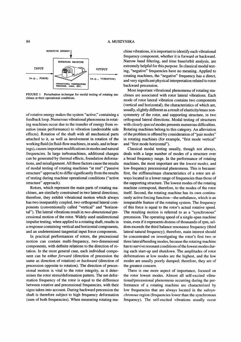
Various types of perturbation systems generating rotat-ing forces can be applied, such as: A) an unbalanced ro-tating free spinner mounted on the shaft and driven bya compressed air jet flow; B) an unbalanced auxiliaryshaft attached to the end of the rotating machine rotorthrough a pivoting bearing, and driven by a separate mo-tor; both A) and B) allow for shaft "nonsynchronous" per-turbation (Fig. 2). Two electromagnetic actuators in XYconfiguration generating sinusoidal forces with 90-degreephase shift can also be applied as input circular forceperturbators. Another device which provides a perturba-tion frequency-independent input force amplitude consistsof radial spring-like elastic elements attached from oneend to the rolling element bearing mounted on the rotor.
86 A. MUSZYNSKA
(a)ONCE-PER-TURN
PROBEPERTURBATION WEIGHTS
ONCE-PER-TURNREFERENCE t]ROLLINGELEMENTBEARING
PE]DISK ROTATEDBY AIR FLOW
AIR NOZZLES
AIR VALVES FOR CLOCKWISEAND COUNTERCLOCKWISEROTATION OF THEPERTURBATION DISK
MACHINESHAFT
-TO AIR SUPPLY
(b)
PERTURBATIONROTOR
KNOWN DISPLACEMENTUNBALANCE / PROBESMASS
STATOR
SELF ALIGNINGROLLING ELEMENT
BEAING
FIGURE 2 Perturbation testing of rotating machines using sweep frequency circular forces generated by rotating unbalance at (a) free spinner; or(b) rigid auxiliary rotor. Rotative speed of the main shaft (2) maintained constant.
On the other ends the springs are mounted in a nonsyn-chronously rotating and (due to its eccentricity) oscillatingring (Fig. 3). This device provides a good resolution in lowfrequency range testing.
In all these systems, the frequency (angular speed) oftheperturbing force is entirely independent from the rotativespeed of the main shaft: the latter rotates at a chosen con-stant speed, while the perturbator provides the input rotat-ing force with sweep frequency. The shaft can be perturbedeither in a forward or a reverse direction. These perturba-tion systems also yield very good results in "passive".
In all above-mentioned methods, as well as other pop-ular modal testing routines (such as impulse testing), theinput into the system is a force; the output is a measuredresponse in terms of mechanical displacement, velocity,
or acceleration. There exists a method applied in rotatingsystems with fluid interactions, in which a displacementis used as an input, and the force is measured at the out-put (Iwatsubo et al. [1980, 1988], Ohashi et al. [1984,1988], Jery et al. [1984], Adkins et al. ([986], Childset al. [1986, 1988], Kanki et al. [1986], Adams et al.[1988], Brennen et al. [1988]). The forced circular dis-placement in an orbital form is generated by a cam mech-anism on the shaft rotating in a fluid environment. Theoutput fluid dynamic force is calculated from the pressuretransducer or load cell readings (Fig. 4). This method pro-vides nonsynchronous perturbation; it is used for identifi-cation of fluid dynamic forces in seals and fluid-handlingmachines. A comparison ofresults yielded by this method,and the input force/output displacement method is given

MODAL TESTING OF ROTORS 87
PULLEY SYSTEM
BEARING
\: MACHINE SIIAFT
ADJUSTABLE ECCENTRICITY
DISK MADE OF ELASTICMATERIAL ACTING AS"RADIAL SPRINGS"
ROLLINGELEMENT
FIGURE 3 Constant force amplitude perturbation device (eccentricity exaggerated).
FIGURE 4 Rotating displacement input and fluid pressure (a) or load cell; (b) output perturbation method.
in the section where perturbation results are compared(see p. xxx).
RESPONSE MEASUREMENTS
Accelerometers are the most popular transducers usedin classical modal testing. The testing results are pre-sented in terms of accelerances (or "inertances") whichare the ratios of response acceleration vectors to inputforce vectors ("vector" means amplitude and phase of aharmonic variable). Accelerometers are the most appro-priate instruments for modal testing of passive structures,which deals usually with high number of modes, with nat-
ural frequencies located in a relatively broad frequencyrange.
In a rotating machine the modes of highest interest arethose of the rotor itself. Most often the rotor modes cor-respond to the lowest modes of the entire machine struc-ture. The first natural frequency may occur in the rangeof 5 to 15 Hz. In this range of frequencies accelerometersperform very poorly. The best transducer in the low fre-quency range is the displacement proximity probe. Whenmounted in casings or bearings, the proximity probe pro-vides relative measurements (shaft motion relative to sup-port motion). For machines with very soft supports theproximity probe can be complemented by a seismic probeproviding casing absolute measurements (for instance, adual transducer).

88 A. MUSZYNSKA
ata Filtering rocssinquisition to perturbation and formattingstem equency
TURBATIONther PROXIMITY0 --7"1- J}{ l------2 BACKWARD)
transduce,, PR,OBCS(pressure, /\ ./ " _."’I v
temperature) ,/ \ It.,,,---[ qL1 "-FORWARO)
p- squared
FIGURE 5 Modal testing of a rotating shaft using circular forward and backward perturbation forces and displacement noncontacting proximitytransducers for vibration response measurements.
Results of modal testing using displacement transduc-ers are usually presented in terms of receptances (thereexists in the literature equally used names, such as "ad-mittances," "compliances," "dynamic flexibilities"). Thereceptances are the ratios of the displacement responsevectors to input force vectors. Receptance vectors arewidely used, for instance, in rotor balancing. (They areoften called "influence coefficients," but the more propername should be "influence vectors.")The use of accelerometers, velocity pickups, or prox-
imity transducers in measurements of mechanical struc-ture vibrations is not only a matter of rational choice,corresponding by matching the best to the type of en-countered conditions, it is also a matter of philosophicalusage--although popular in modal analysis applications,accelerometers are not widely used in on-line monitoringand diagnostics ofrotating machinery malfunctions. Rotordisplacements, not accelerations, are the most meaningfulsignals for the operating personnel.
Specific changes in rotor displacements (vibration am-plitudes, as well as static positions) relative to machinecasing directly indicate what type of malfunctions the ma-chine develops. Changes in the static positions indicatechanges in the alignment state. These data assist in pre-diction of fluid whirl/whip self-excited vibrations, as wellas shaft crack prevention. A specific content of vibrationsignals indicates presence of unbalance, misalignment,rotor-to-stator rubs, loose parts, shaft crack propagation,and other malfunctions of the rotating machine.The most harmful vibrations for the integrity of the ro-
tating machine are low frequency, subsynchronous vibra-tions, resulting usually from an instability action transfer-
ring rotational energy into vibrations. Acceleration ampli-tudes are proportional to the square of vibration frequency.This means that when measuring rotor vibration by usingaccelerometers, the higher frequency components becomedominant, indicating high amplitudes. The low frequencycomponents look insignificantly small, even though theymight have very high amplitudes in terms ofrotor displace-ments. In addition, accelerometers are most often installedoutside the rotor casing; thus they measure vibrations ofthe outside structure, not the vibrations of the rotor, whichis the main source of vibration. During transmission fromthe source through the structure, vibration becomes atten-uated, the degree ofattenuation depending on the structuretransmissibility.
In summary, in the rotating machine perturbation test-ing, the most useful instruments to measure rotor re-sponses are displacement transducers mounted in XYconfiguration (Fig. 5), with a Keyphasor(R) once-per-turnmarker for phase reference.
NONSYNCHRONOUS SWEEPFREQUENCY PERTURBATIONTESTING AND DYNAMIC STIFFNESSIDENTIFICATION ALGORITHM
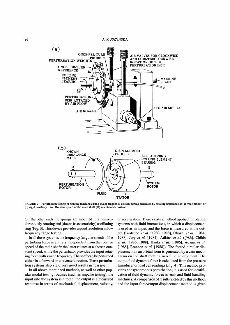
In the classical modal testing, identification of the struc-ture modal parameters is usually based on curve fittingof results presented in the form of receptances (Ewins,[1984], Fig. 6). Much better identification results are
MODAL TESTING OF ROTORS 89
a) RECEPTANCE APPROACH
" 10 100 IHzl t773 100 (Hz) 1000
:2
b) DYNAMIC STIFFNESS APPROACH
<4 6 %, K -0.0039 60 2 + 480>-o 14
o,,z co
PERTURBATION FREQUENCY
..-t SOUARED IRADIS- 100}
FIGURE 6 Identification of modal parameters: (a) curve fitting of receptances (Ewins 1984])’ (b) straight-line fitting of dynamic stiffness results(Muszynska [1986]).
obtained, however, when a Dynamic Stiffness approachis applied. Straight lines of dynamic stiffness componentsare definitely the best to fit. A dynamic stiffness algorithmfor identification of modal parameters of a rotating ma-chine rotor using nonsynchronous sweep frequency per-turbation testing is outlined below.
Rotor responses to rotating force excitation bring mean-ingful data for identification ofthe system parameters. Theidentification procedure involves matrix inversion, thus acomputer is necessary for experimental data acquisitionand processing.
Consider a modal of a nonsymmetric (laterallyanisotropic), anisotropically supported, flexible 2n degreeof freedom (2n lateral mode) rotor rotating at a constantspeed f2 (Fig. 5):
[[D1][D12]]r[M1 ][M12]] [,] 4- []L[M2]][M2]J DZl][D2]J
[[[K1][K12]]qK21][K2]
[Z] [F] d/dt (1)
where Z col[xl Xp xn,Yl yp Yn]represents rotor deflections at its p n axial lo-cations in two orthogonal directions x and y. The systemparameters are represented by the matrices"
[Mq], [Mq,3_q] [Dq], [Dq,3_q] [gq], [gq,3-q],q= 1,2,
which are inertia, damping, and stiffness matrices corre-spondingly. The matrices Dq,3_q contain "cross" damp-ing terms, matrices [Kq,3_q] contain elements of the"cross" stiffness type. Both these matrices usually dependon the rotative speed 9. The vector [F] contains con-trolled perturbation (excitation) forces. For identificationof the system parameters, a controlled rotating perturba-tion force is applied consecutively at "r" (r 1,..., n)axial locations of the rotor in either forward (s 1) orbackward (s 2) direction. The "n" pairs of displace-ment transducers in an XY configuration are mounted at"p" (p n) axial locations of the rotor (Fig. 5).When the force is applied at the rth location, the excitation

90 A. MUSZYNSKA
vector used in nonsynchronous perturbation is, therefore,
[F] col[0 O, Fsr cos(cot + tsr), 0 O, (-1)s+l
Fsr sin(cot + tsr), 0 ,0], s 1, 2 (2)
where
/qsll
[Aqs]
Lqsnl
Aqsln
[aqspreJtqspr],qsnn (6)
where co is perturbation frequency, Fsr and tsr are theperturbation force amplitude and phase, respectively. Notethat the perturbation frequency w is entirely independentfrom the rotative speedThe rotor forced response to exciting force (2) based on
model (1) is as follows:
[Z] col[Alslr cos(cot + 0tlslr )
Alsnr cos(cot + Otlsnr), A2slr sin(wt + Ct2slr
A2snr sin(cot + Ot2snr)] (3)
where Aqspr, Otqspr are amplitudes and phases of theresponses, narrow-band filtered to the perturbation fre-quency. All phases are measured from the same once-per-rotation marker. By substituting (3) into Eqs. (1), elimi-nating time-related functions, and using Euler’s complexnumber transformations, the algebraic set of 2n equationsis obtained"
I[A lspreJalspril FsreJsr {col O, 1,[tO]L[A2sprejtzwr j- 0 O, (-1)s+l,
o o]}(4)
where j and
[K1]+jw[D1]_oo2[Ml
j ([K21]+"jw[D21 ]-o2 M21 ])
-j ([K12]+jto[D12]-o92[M12]) ]K2]+joo[D2]-ro2 M2
is the system complex dynamic stiffness matrix. Thenonzero components at the right side of Eq. (4) are atthe rth and (n + r)th rows.
For the sequence of n experiments, in which the forceis applied consecutively at r 1, 2 n locations, firstin forward (s 1) then in backward (s 2) directions,the set of 2n equations is obtained:
[[All] [A12]] [[F1] [F2] ][to][a21] [A22] [F1] [-F2]
(5)
Fs diag[Fslej$*’ Fsnej$*n ],q,s= 1,2
In Eq. (6) qspr Aqsprejqspr, q, s 1, 2, p, rn represent response vectors (in complex number
sense), components of the response nonsingular matrix.Note that the number of tests (2n) must correspond to thenumber of identified modes, thus certain knowledge onthe system behavior is required ahead of time, to avoidsingularity of the matrix [Aqs]. Equation (5) yields themain equation for identification of the system parameters"
[[F1] [F2] ] [[All] [A12]]-l
[x]=[_[Fl] [-F21 L[A21] [A221(7/
The identification procedure is reduced to the followingexpressions, representing the rotor dynamic stiffness com-ponents:
[gq] -co2[Mq] -Re{[(-1)q[F2] + [HI]][H2]};
ro[Oq] -Im{[(-1)q[F2] + H]][H2]}; (8)
oo[O3_q,q] Re{[(-1)q[F2] [H1]][H2]};
[K3-q,q] co2[M3-q,q] Im{[(-1)q[F2]
[H1]][H2]}; q l, 2 (9)
where
[HI] [F1][A3-q,1]-I[A3-q,2],
[H21 [[Aq,2] [Aq,1][A3-q,1]-l[A3_q,2]]-1
With the frequency sweep excitation (co variable from zeroto a selected value covering the range ofn natural frequen-cies of the system the results (6) to (9) are eventuallygraphically presented versus co or o92 for the easiest curvefitting of straight lines.
Note that the model (1) takes into consideration 2n ro-tor/bering/seal system coupled modes. The vector Z con-tains multimode modal coordinates, discussed on p. xxx.Using this approach, the identification provides parame-ters of the coupled system, not only modal parameters ofdecoupled modes. The method is very effective for sys-tems with a low number of modes (Muszynska [1986],
MODAL TESTING OF ROTORS 91
Muszynska et al. [1989b]), and is extremely useful if theknowledge on all connecting masses and stiffnesses in thesystem is required. If the number of modes in the chosenfrequency range is not known ahead oftime, the additionalmeasurements may serve for modal correction factorcalculations, as discussed by Muszynska et al. [1989b].
APPLICATION OF SWEEP FREQUENCYROTATING FORCENONSYNCHRONOUS PERTURBATIONTO THE ONE-MODE ROTOR/BEARINGSYSTEM. IDENTIFICATION OF WHIRLRESONANCE AND FLUID DYNAMICFORCES
The nonsynchronous frequency swept rotating force in-put perturbation method has proved to be very efficientfor identification of bearing and seal fluid dynamic forces.As a result of over ten years of testing and research, animproved model of fluid dynamic forces in lightly loadedbearings, in seals and fluid-handling machines, has beenproposed (Muszynska 1988a]). The model was identifiedexperimentally using the perturbation technique. A similarfluid force model was previously developed theoretically,and has existed in a simplified version in rotordynamic lit-erature for at least 25 years (Bolotin [1963]; Black [1969,1980]). It has not, however, been fully exploited.The most important result of perturbation testing iden-
tification of the fluid forces was introduction of the "fluidcircumferential average velocity ratio," k, as a functionof shaft eccentricity. It has replaced the assumed constant"1/2" widely used in other fluid force models.The results of perturbation testing also, yielded, con-
clusions regarding modal behavior of mechanical systemswith fluid interactions. It was shown that the value "kf2"(fluid circumferential average angular velocity) represents(with approximation related to damping) arotor/bearing orrotor/seal system natural frequency (Muszynska 1986]).It is associated with the specific "fluid whirl" mode of therotor.
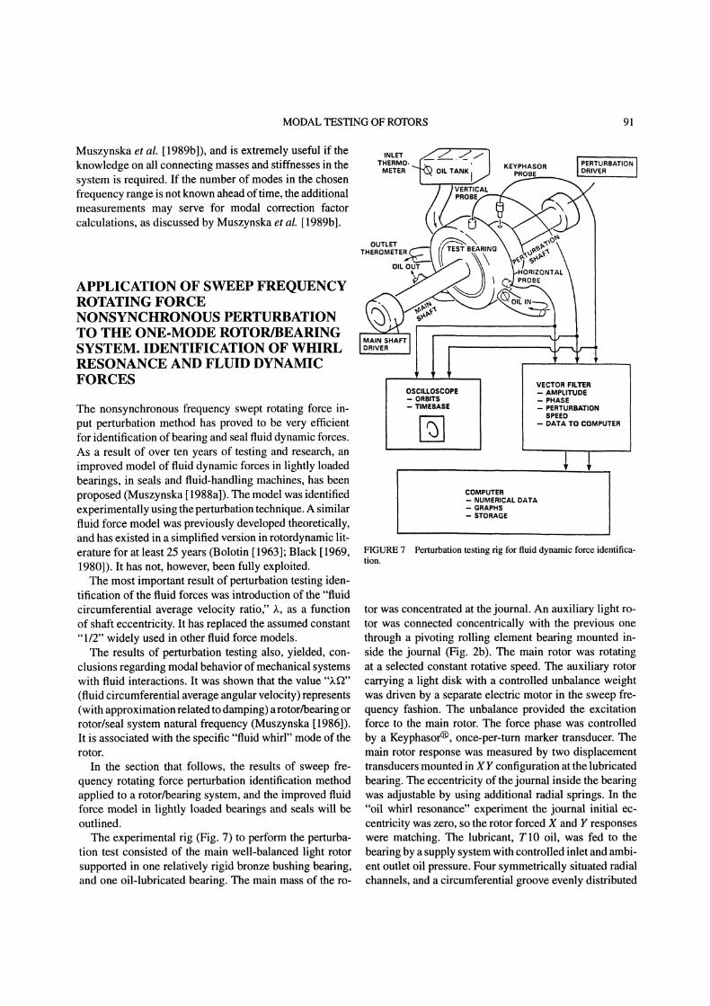
In the section that follows, the results of sweep fre-quency rotating force perturbation identification methodapplied to a rotor/bearing system, and the improved fluidforce model in lightly loaded bearings and seals will beoutlined.The experimental rig (Fig. 7) to perform the perturba-
tion test consisted of the main well-balanced light rotorsupported in one relatively rigid bronze bushing bearing,and one oil-lubricated bearing. The main mass of the ro-
VECTOR FILEROSCILLOSCOPE AMPLIOE
ORBITS PHASEMEBASE PERTURBATION
SPEEDDATA TO COMPUTER
COMPUTERNUMERICAL DATAGRAPHSSTORAGE
FIGURE 7 Perturbation testing rig for fluid dynamic force identifica-tion.
tor was concentrated at the journal. An auxiliary light ro-tor was connected concentrically with the previous onethrough a pivoting rolling element bearing mounted in-side the journal (Fig. 2b). The main rotor was rotatingat a selected constant rotative speed. The auxiliary rotorcarrying a light disk with a controlled unbalance weightwas driven by a separate electric motor in the sweep fre-quency fashion. The unbalance provided the excitationforce to the main rotor. The force phase was controlledby a Keyphasor(R), once-per-turn marker transducer. Themain rotor response was measured by two displacementtransducers mounted in XY configuration at the lubricatedbearing. The eccentricity of the journal inside the bearingwas adjustable by using additional radial springs. In the"oil whirl resonance" experiment the journal initial ec-centricity was zero, so the rotor forced X and Y responseswere matching. The lubricant, T10 oil, was fed to thebearing by a supply system with controlled inlet and ambi-ent outlet oil pressure. Four symmetrically situated radialchannels, and a circumferential groove evenly distributed
92 A. MUSZYNSKA
REVERSE
VERTICAL I
isl ,
100 ’ /..r.r..q ,75
[.9 {M) WITH MASS
< srmosr --’0
25
ORIGINAL SYSTEM
(SM) WITII SPRINGS & MASS
FORWARD
-5O
-75
-100
-125
PERTURBATION SPEEDIrad/s 1001
(M)
tSM)
’-150 (O)
(SM)
5 mils
r/- 64.4c poisefl = 200 rad/s 00
(s)’ - ,’-3 -2 -1 0 1 2 3
PERTURBATION SPEED w [rad/s 100]
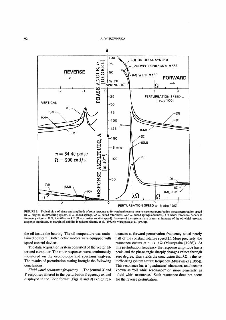
FIGURE 8 Typical plots of phase and amplitude of rotor response to forward and reverse nonsynchronous perturbation versus perturbation speed(0 original rotor/bearing system, S added springs, M added rotor mass, SM added springs and mass). Oil whirl resonance occurs atfrequency close to f2/2, identified as .f2 (f2 constant rotative speed). Increase of the system mass causes an increase of the oil whirl resonantresponse amplitude, as margin of stability is reduced (Bently et al. [1982b]; Muszynska et al. [1990]).
the oil inside the bearing. The oil temperature was main-tained constant. Both electric motors were equipped withspeed control devices.The data acquisition system consisted of the vector fil-
ter and computer. The rotor responses were continuouslymonitored on the oscilloscope and spectrum analyzer.The results of perturbation testing brought the followingconclusions:
Fluid whirl resonancefrequency. The journal X andY responses filtered to the perturbation frequency w, anddisplayed in the Bode format (Figs. 8 and 9) exhibit res-
onances at forward perturbation frequency equal nearlyhalf of the constant rotative speed . More precisely, theresonance occurs at o .f2 (Muszynska [1986]). Atthis perturbation frequency the response amplitude has apeak, and the phase angle sharply changes values throughzero degree. This yields the conclusion that )g2 is the ro-tor/bearing system natural frequency (Muszynska 1986]).This resonance has a "quadrature" character, and becameknown as "oil whirl resonance" or, more generally, as"fluid whirl resonance?’ Such resonance does not occurfor the reverse perturbation.

MODAL TESTING OF ROTORS 93
earoaar,o I K-M t0 + K0- Mf(a’-’fl)z
EVERSE PERTURBATION SPEED[ RAD/s]90-100 100 200 300 400
-30SPEED RATIO
-320 PERTURBATION O---60 XX .3000 == "4 PE;;ON
/m =7g ]fiO =1000RPM (105rad/sl E
1[q=59cpoiseH 13000 (314) /004
/=9:poise0.5
oA A
-100/ / /.100//200 300 400
o. o. o.7 l , PERTURBATION SPEED [RAD/s]
FIGURE 9 Phase and amplitude ofrotor response versus perturbation-to-rotative speed ratio for various values of rotative speeds, 2. Increaseof amplitudes with increases of 2 due to decrease of margin of stability(Bently et al. [1992a, b]; Muszynska [1986, 1990]).
Dynamic stiffness format. Using the dynamic stiff-ness algorithm (Eqs. (7) to (9)), the force/response datawas then processed, and presented in the dynamic stiff-ness format. For the isotropic single complex degree offreedom system (x -t- jy z; j Sf) the journal lat-eral response was z A exp[j (cot + c0], where A and ot
are response amplitude and phase filtered to perturbationfrequency co. The Direct (DDS) and Quadrature (QDS)dynamic stiffnesses were obtained as
mrco2DDS cos( or),
A
mrco2QDS sin(a ) (10)
A
where m, r, are the input perturbation force unbalancemass, radius, and angular orientation, respectively.The dynamic stiffness components versus perturbation
frequency are presented in Fig. 10. The direct dynamicstiffnesses are parabolas; the quadrature ones are straightlines, thus the identification of their parameters is rela-tively easy.
Fluid force model. The curve fitting of the dy-namic stiffness components allowed identification of thefluid force model applicable for lightly loaded bearingsand seals (Muszynska [1986, 1988a]; Muszynska et al.
FIGURE l0 Rotor/bearing direct and quadrature dynamic stiffnessesversus perturbation speed. Identification of fluid force parameters.(Higher rotative speeds caused an increase of oil temperature, thus adecrease of fluid radial damping reflected in quadrature dynamic stiff-ness graphs with lower slopes) (Muszynska [1986, 1990]). K, M arerotor stiffness and mass, respectively.
[1990]). The following fluid force model
F [g0 + jD(co- kf2) My(co- ))2]Aejt (11)
was provided directly from the dynamic stiffness graphs;DDS Ko Mf(co- ))2, QDS D(co- kfa). (Notethat the raw data in Fig. 10 also contain, the mechanicalsystem parameters K and M which were subtracted, anddo not appear in the fluid force model (11).)The differential form of the fluid force model in coor-
dinates rotating with angular velocity Lfa is (Muszynska[1988a]):
F KOZr + D.r + M.l’,r z x at- jy zrej’t
(12)
In stationary coordinates z x + jy the fluid force modelbecomes:
F KOZ + D(. j.faz) + Mf( 2jkf2. .22z)
(13)
In Eqs. (11) to (13) K0, D, and Mf are fluid radial stiff-ness, radial damping, and inertia effect, respectively, all of
94 A. MUSZYNSKA
0 15i..
z =7o /-2oi PERTURBATION SPEED
[M x
-5-2-1 I2
ps 4
z 2 / /SLOPE IS
_1 [ ECCENTRICITY 0 4 Ib-sec/in
/ 62.5cpoise/ 2000 RPM /<
3.5g x 30mm - -2 - PERTURBATION3 SPEED
-6-4-3-2-1 = /-21 [RPM x 101
D -630 Ib/in
-3
/// -4
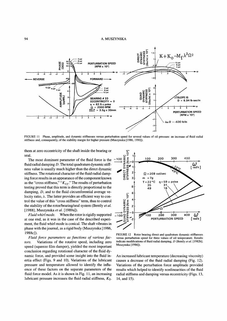
FIGURE 11 Phe, amplitude, d dynamic stiffnesscs versus perturbation speed for several values of oil pressure: incree of fluid radialstiffness d, consequently, of the stability margin for higher pressure (Muszynska [1986, 1990]).
them at zero eccentricity of the shaft inside the bearing orseal. oThe most dominant parameter of the fluid force is the -1 oo, , E
fluid radial damping D. The total quadrature dynamic stiff--o
>’aness value is usually much higher than the direct dynamic t 2stiffness. The rotational character of the fluid radial damp- u u.=:g
3ing force results in an appearance ofthe component knownas the "cross stiffness," "Kxy." The results of perturbationtesting proved that this term is directly proportional to the 8
damping, D, and to the fluid circumferential average ve-locity ratio, ,k. The latter provides an efficient way to con-trol the value of this "cross stiffness" term, thus to controlthe stability of the rotor/bearing/seal system (Bently et al.[1988], Muszynska et al. [1989a]).
Fluid whirl mode. When the rotor is rigidly supportedat one end, as it was in the case of the described experi-ment, the fluid whirl mode is conical. The shaft vibrates inphase with thejournal, as a rigid body (Muszynska 1986,1988c]).
Fluid force parameters as functions of various fac-tors. Variations of the rotative speed, including zerospeed (squeeze film damper), yielded the most importantconclusion regarding rotational character of the fluid dy-namic force, and provided some insight into the fluid in-ertia effect (Figs. 9 and 10). Variations of the lubricantpressure and temperature allowed to identify the influ-ence of these factors on the separate parameters of thefluid force model. As it is shown in Fig. 11, an increasinglubricant pressure increases the fluid radial stiffness, K0.
100 200 300 400
-209 rad/sec
rn =7gT=22C 1=59 cpoise
35 3149
rad/s
00 200 300 400 (PERTURBATION SPEED rad/s
FIGURE 12 Rotor bearing direct and quadrature dynamic stiffnessesversus perturbation speed for three values of oil temperature. Resultsindicate modifications of fluid radial damping, D (Bently et al. 1982b];Muszynska [1986]).
An increased lubricant temperature (decreasing viscosity)causes a decrease of the fluid radial damping (Fig. 12).Variations of the perturbation force amplitude providedresults which helped to identify nonlinearities of the fluidradial stiffness and damping versus eccentricity (Figs. 13,14, and 15).

MODAL TESTING OF ROTORS 95
2000
PERTURBATION FREQUENCYTO ROTATIVE SPEED RATIO
FIGURE 13 Direct dynamic stiffnesses with nonlinear effects.(perturbation by increasing perturbation force magnitude, rncontrolled input unbalance weight mass) (Bently et al. [1985a, 1986a]"Muszynska et al. 1990]).
fl 2500 RPMrn _1.75_g_
3.5
28
TO ROTATIVE SPEED RATIO
FIGURE 14 Quadrature dynamic stiffness with nonlinear effects (per-turbation by increasing perturbation force magnitude, m controlledinput unbalance weight mass) (Bently et al. [1985a, 1986a]; Muszynska,et al. 1990]).
COMPARISION OF THE RESULTS OFPERTURBATION TESTING USINGROTATING FORCE INPUT ANDROTATING DISPLACEMENT INPUT
There are two main perturbation techniques of nonsyn-chronous one-mode testing used for identification of fluidforce models in rotor/bearing, rotor/seal systems, and influid handling machines (mainly pumps). The basic ad-vantage of these methods is the rotational character of the
input function, in forward or reverse direction (the sameor opposite to rotor rotation). This allows for independentidentification offorward and backward modes ofthe rotat-ing system. The two perturbation techniques differ by theinput/output functions (Figs. 2 and 4). They are follows:
FORCE: FeJt
DISPLACEMENT: Aejt FORCE: (Fr+jFt)ejwt
where A is rotor displacement amplitude, ot is rotor re-sponse phase (also c arctan(- Ft/Fr)), w is rotorperturbation (excitation) precessional frequency (usuallyvarying from zero to some Wmax), and Fr, Ft are radialand tangential forces, acting on the rotor. These forces areobtained by integrating the fluid pressure or measuringforces outside an elastically supported seal or bearing; Fis the input force amplitude.
In both techniques the objective is identification of thetransfer function of the system. More precisely, the func-tions sought are x(w) Complex dynamic stiffness, or/-)(w) x(-log)_= Transfer function Complex dynamiccompliance or- the system. The result most often obtainedfrom either technique is the complex dynamic stiffness:
Fr + jFtx (09) when inputting displacement (14)
A
F jcx(w) --e- when inputting force (15)A
The complex dynamic stiffness components for both tech-niques are as follows:
Direct dynamic stiffness _= DDSA
Quadrature dynamic stiffness QDSA
F cos ot
A
(16)
F sinot
A
(17)
By limiting the input to a circular periodic function, bothmethodologies should yield exactly the same results, pro-vided that the system is linear, and the instrumentationallows for comparable signal-to-noise ratios.
Both techniques are known in mechanics as "force ex-citation" and "kinematic excitation," respectively. Theyboth serve well for identification of the lowest mode gen-eralized (modal) parameters of the system.
Figures 8, 9, 10, 16 and 17 illustrate the basic re-suits obtained by various researchers who used either of

96
PERTURBATION FREQUENCY
A. MUSZYNSKA
PERTURBATION FREQUENCY
SHAFT ECCENTRICITY A
FIGURE 15 Identification of fluid radial stiffness nonlinearity (Muszynska et al. 1990]). Stiffness nonlinear function results from subtraction ofdynamic stiffnesses for nonlinear and linear cases.
the nonsynchronous perturbation techniques. FollowingEqs. (14) and (15), the dynamic stiffness graphs versusperturbation frequency (Figs. 10 and 17) are similar forboth techniques. The response vectors versus perturba-tion frequency are presented in Figs. 8, 9 and 16, in theform ofBode plots. Note that, in the technique which usesforce input, the displacement response vector to forward
perturbation has a form characteristic for responses of aone-mode system to a periodic excitation with sweep fre-quency (Figs. 8 and 9). The occurrence of a resonance isobvious. The peak amplitudes may become very high ifthe shaft rotative speed approaches the 1/. value of therotor "mechanical" natural frequency, corresponding to itsfirst bending mode ( is the fluid circumferential average

MODAL TESTING OF ROTORS 97
3rio
.<l:cl o
.Pressure-***Load cell" +++a-- 588 kPa
25 .5 .75
Fr+jFt
0 .25 .5 .75
FREQUENCY RATIO, wFIGURE 16 Force response phase and amplitude versus perturba-tion frequency (perturbation by displacement). Courtesy of T. Iwatsubo[1988].
velocity ratio), as discussed by Muszynska [1986, 1990].In fact, instability occurs when both direct and quadraturedynamic stiffnesses are nullified at the same frequency.In comparison to the response of a classical mechanicalsystem, the response phase is, however, ahead of the in-put force. This indicates the "quadrature" nature of thisparticular resonant phenomenon. The resonant frequencyhas been identified as if2. (In machinery it was some-times called "bearing resonance?’). The occurrence of theresonance suggests that if2 represents one of the systemnatural frequencies. This natural frequency is generatedpurely by the fluid/solid interaction. The rotating shaftdrags the fluid into circumferential motion, generating thefluid rotating forces which act on the shaft in a feedbackloop. This fluid-related quadrature resonance was docu-mented by Stone & Underwood in 1947, and again byHull in 1955, but these excellent works were not immedi-ately pursued.
3-D impeller
2-D impeller
-1.5 -1 -0.5 0 0.5PERTURBATION FREQUENCY TO ROTATIVE SPEED RATIO {d/
10 -" Ft3-D impeller -"2-D impeller .a...,.....
-1.5 -1 -0.5 0 0.5 1.5
PERTURBATION FREQUENCY TO ROTATIVE SPEED RATIO d/
FIGURE 17 Direct and quadrature dynamic stiffness versus perturba-tion frequency for the system with input circular displacement, andoutput force (see Eq. [14]). Courtesy of H. Ohashi [1988].
By inputting a constant circular displacement, and mea-suring the output in terms of forces, the accuracy of theresults is lower (mainly due to poor phase resolution), andthere is no clear physical interpretation of the results. Theplot of force response amplitude versus perturbation fre-quency has an "anti-resonance" shape, a concave curve,like a mirror image of displacement response amplitudeversus frequency (Fig. 16). The phase is the same in bothtechniques. It is obvious, because by definition, the phaserepresents the angle between the input vector and outputvector, independently of the nature of the input and outputfunctions. Note that the dip point of the response forceamplitude and phase drop occur around one half of the ro-tative speed, i.e., the fluid circumferential average velocityratio I is equal to about one half. The notion of the "forceresonance," or rather "anti-resonance," is not known inmechanics. That is why the researchers who have used theinput force methodology, and adopted direct physical in-terpretation of the results, have been more fortunate thanthose who use forces as outputs.
Note the advantage of the circular perturbation, as op-posed to unilateral perturbation, in impulse testing. Theresults of forward perturbation (rotation and precession inthe same direction), and backward perturbation (opposeddirection) are significantly different (Fig. 8). The reso-nance occurs only for the forward perturbation, that is,

98 A. MUSZYNSKA
the "quadrature" natural frequency Lf2 of the system hasonly the plus sign (classical "direct" natural frequenciesgoverned by stiffness and mass have + and signs).
the direction opposite to shaft rotation makes dramaticchanges in the fluid circumferential average velocity ratiovalues, considerably lowering them, and improving rotorstability features.
ANTISWIRL SEAL TESTING
The sweep.frequency rotating force nonsynchronous per-turbation method was applied to identify the fluid forceparameters in antiswirl seals equipped with radial andtangential inlet ports (Grant [1991]). The results provideclear effects ofthe input flow pattern on fluid force compo-nents. Water was used for series ofexperiments. Figure 18illustrates an example of the data presented in terms of dy-namic stiffness components for the seal input flow throughradial or antiswirl ports for three rotative speeds. Basedon this type of data, the identified fluid force parameters,namely, circumferential average velocity ratio ., radialstiffness, and damping reduced from approximately 70runs covering the range from 3 to 80 psi water pressure,are presented in Figure 19. The graphs clearly show gen-eral trends of these parameters for radial and antiswirlinlets (Muszynska et al. 1992]).
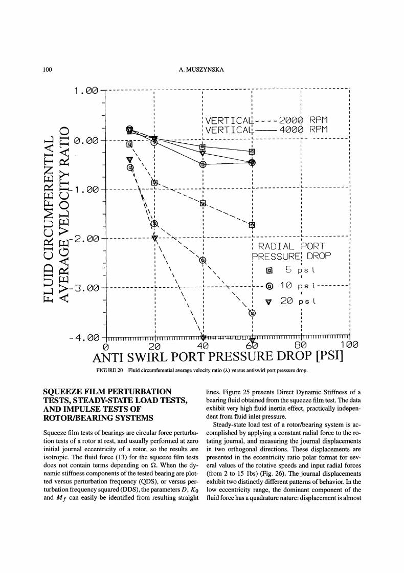
Figure 20 illustrates fluid circumferential average ve-locity ratio versus anti-swirl port pressure drop for severalcases of mixed radial and tangential inlets. As seen inFigures 19 and 20, the antiswirl input fluid injection in
..st! K0- Mtv2- Mf(ta--Af)
r /
_PERTURBATION, ..= | FREQUENCY, w [kcpm]
:Sb radi n 2 krpmo raM fl 4 krpm/ antiswirl
rpm
PERTURBATION FREQUENCY ,[kcpm]
FIGURE 18 Direct and quadrature dynamic stiffnesses versus pertur-bation frequency of the seal with either radial or antiswirl inlet ports(Grant [1991]; Muszynska et al. [1992]).
ROTOR/BEARING SYSTEMIDENTIFICATION COVERING WHIRLAND WHIP MODES
In the tests for identification of the fluid whirl resonance,the main rotor was deliberately rigid and light, so thatits first natural frequency of the bending mode (conven-tionally called here "whip") was well above the rangeof perturbation frequencies. The next series of tests con-cerned the rotor/bearing system, covering both whirl andwhip modes. The main rotor was made more elastic, and aheavy disk was mounted at rotor mid-span (Fig. 21). Themain rotor first natural frequency became much lower, andplaced in the range of the applied perturbation frequen-cies. Since more modes were involved, the test requiredadditional data. Perturbation, therefore, was applied ei-ther at the journal (as previously), or at the rotor disk(using an unbalanced, pulley-driven spinner). Each time,the response data was collected from XY proximity trans-ducers mounted at the bearing, and at the disk. Followingthe identification algorithm (7) to (9), the 2 2 matrixof complex dynamic stiffness components was identified.The results are presented in the form of Bode plot matri-ces from the experimental data, as well as from calculatedanalytical data based on the identified parameters of thesystem. The system model (Fig. 22) is as follows (Bentlyet al. [1985c]):
Md,d + Dsd + (K1 + K2)zd K2ffZb
Fdej)t for the first test
/ 0 for the second test
Mb,b + Mf(,b 2j.f2ib ,2f22Zb) + D(b
j,2Zb) + (Ko + K3)zb + K2(crZb Zd)
0 for the first test(18)
Fbejwt for the second test
where Md, Mb are disk and journal modal masses corre-spondingly, K1 and K2 are the main shaft partial modalstiffnesses, cr is modal correction factor, K3 is the exter-nal supporting spring stiffness, Ds is rotor external modal

MODAL TESTING OF ROTORS 99
i- -I**** 0 rpm Radial only
-ooooo 2000 rpm Radial only ’x:xx:x 4000 rpm Radial onlyaaaaa 0 rpm Antiswirl only,1111 2000 rpm Antiswirl only __,__,ooooo 4000 rpm Antiswirl onlyw,.,..scos,.T 1,002 c,nti,olseA..._ _,_ j_(I[J*F (O*C)
, ,’*"r r -(1 q T"--,--’I-- r
--,--.--.--.-.--.--.--,--.--.--,
,--,--,--,-,,-,--,--,--,--,--,---I
4---i--7,11Fr " --|
,4 _,._, 0,___ ,.,_’_, ’,---- ..--.--.----.----,----,---.----.---,
Ill Oltll
I []
_It I_
ii0 2 4 6 O 10 12 14 16 10 20 22
Mass Flow Rate [lb*sec/in*sec xlO-]
jI’
&
.,
I,0,’ ,0, ,0’ ,I,
Oi 0 OI
Od IIII
25---’ ’--’,-,,,,,,’*;"’:r’
_- po
Ra ia"Drt,voct’et,"
-.25-0 2 4 6 8 10 12 14 16 10 20
Mass Flow Rate [lb*sec’/in*sec xl0-’]FIGURE 19 Identified fluid radial stiffness (K0), fluid circumferential average velocity ratio (X), and damping (D) of the antiswirl seal versusmeasured mass flow rate (Grant [1991]" Muszynska et al. 1992]).
viscous damping, Mf, D, Ko are, as previously, the fluidforce parameters, Fd and Fb are perturbation force am-plitudes (Fd mpdrW2, Fb mpbrw2). The resultspresented in the form of Bode plot matrix exhibit tworesonant ranges: the whirl resonance at lower perturba-tion frequency discussed on p. xxx, and the "whip" reso-
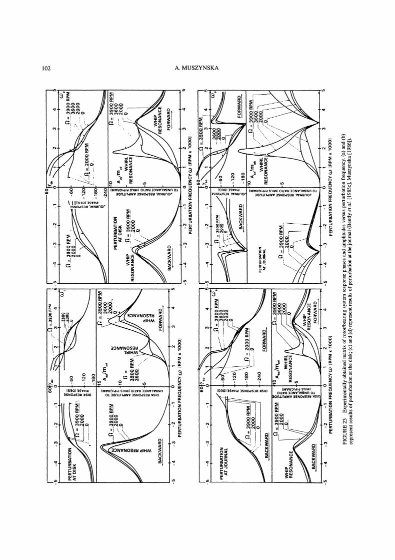
nance corresponding to the rotor first bending mode. Usingthe dynamic stiffness algorithm (Eqs. (7) to (9)), the sys-tem parameters were identified. As it can be seen fromthe corresponding experimental (Fig. 23) and analytical(Fig. 24) results, the identification process provided verygood agreement, and proved the model adequacy.
100 A. MUSZYNSKA
:RADIAL PORTPRESSURE: DROP
pst
ANTI SWIRL PORT PRESSURE DROP [PSI]FIGURE 20 Fluid circumferential average velocity ratio () versus antiswirl port pressure drop.
SQUEEZE FILM PERTURBATIONTESTS, STEADY-STATE LOAD TESTS,AND IMPULSE TESTS OFROTOR/BEARING SYSTEMS
Squeeze film tests of bearings are circular force perturba-tion tests of a rotor at rest, and usually performed at zeroinitial journal eccentricity of a rotor, so the results areisotropic. The fluid force (13) for the squeeze film testsdoes not contain terms depending on f2. When the dy-namic stiffness components of the tested bearing are plot-ted versus perturbation frequency (QDS), or versus per-turbation frequency squared (DDS), the parameters D, K0and My can easily be identified from resulting straight
lines. Figure 25 presents Direct Dynamic Stiffness of abearing fluid obtained from the squeeze film test. The dataexhibit very high fluid inertia effect, practically indepen-dent from fluid inlet pressure.
Steady-state load test of a rotor/bearing system is ac-complished by applying a constant radial force to the ro-tating journal, and measuring the journal displacementsin two orthogonal directions. These displacements arepresented in the eccentricity ratio polar format for sev-eral values of the rotative speeds and input radial forces(from 2 to 15 lbs) (Fig. 26). The journal displacementsexhibit two distinctly different patterns of behavior. In thelow eccentricity range, the dominant component of thefluid force has a quadrature nature: displacement is almost

MODAL TESTING OF ROTORS 101
13.5"’12.5"
7"" 7
t’l= 11.5"’
e3= 9.5"
l I-1_IqliFIGURE 21 Test rig (Bently el al. [1985c]). (1) main motor; (2) elastic coupling; (3) rigid pivoting bearing; (4) main shaft, (5) disk XYnoncontacting probes; (6) main rotor disks; (7) disk perturbation motor; (8) perturbation driving system; (9) Keyphasor(R) probe; (10) disk withperturbation unbalance; (11) bearing XY noncontacting probes; (12) rotor weight balancing springs; (13) main rotor journal; (14) oil-lubricatedbearing with radial clearance 25/zm; (15) pivoting bearing connecting auxiliary shaft to the journal; (16) auxiliary perturbing shaft; (17) disk withperturbation unbalance; (18) Keyphasor(R) probe; (19) rigid bearing; (20)elastic coupling; (21) perturbation motor.
Zd= :d+JY d
Zb
x b + JYb
K2
m pb
M b
ro2
FIGURE 22 Model of the isotropic rotor/bearing system, taking into account two complex modes.
perpendicular to the applied force, that is, the tangential(quadrature) component of the fluid force, Dkf2, is domi-nant. For a high rotative speed the angle between the inputforce and journal response is even larger than 90 whichindicates a high fluid inertia effect opposing the fluid filmradial stiffness* (Bently et al. 1985a]).
In order to identify the fluid force parameters, the in-put force vector was divided by the response vector, split
*The fluid dynamic force for this test is F (Ko- Dj,kf-Mf,k22)z (see Eq. (13)); the force balance is F Pejx where P, yare amplitude and angular orientation of the input constant radial force.By measuring "z," the fluid force can be identified.
into collinear and perpendicular to the input force com-ponents, and presented versus eccentricity ratio (Fig. 27).While the quadrature components identified as kD (ro-tative speed eliminated) exhibit classical, quite regularform, the fluid film dynamic stiffness in the direction ofload, namely, K Mf22 confirms the existence ofthe strong fluid inertia effects, and exhibits two distinctpatterns of behavior characteristic for the low and higheccentricities.A similar steady-state load test was performed on a low-
pressure oil bearing (Fig. 28). While the fluid inertia effectwas smaller, similar behavior patterns in the two ranges ofeccentricity were observed. In both cases (Figs. 26 and 28)
102 A. MUSZYNSKA
IIN’l,’lO/dld S’IINI OLLVI 30NV’IVRNf’I Ol:JCln1"ldlNr 3SN
\.

MODAL TESTING OF ROTORS 103

104 A. MUSZYNSKA
SQUEEZE FILM TEST10 MIL DIAMETRALCLEARANCE
70F
PARAMETERS"
K 800 lb/in
Mf 0.0223 lb see/in
for 15 psi pressure
K 300 lb/in
Mf 0.0234 lb see/in
for 4 psi pressure
4
,, , , ,
164 6 x 10⁴ 105 1.6 x 10
PERTURBATION FREQUENCY SQUARED, o2[rad s]FIGURE 25 Direct Dynamic Stiffness of a cylindrical beating (l/d0.74) obtained from the squeeze film test (Bently et al. [1985a]).
o
.5ECCENTRICITY RATIO
STEADY STATE LOAD TEST5.5 MIL DIAMETRAL
LOAD DIRECTION CLEARANCE80F
og,’.., 15 PSI OIL SUPPLY........,r.o,.-,, PRESSURE"--.’o,
"’" , / :a 00 rad/s \..... 300 rad/s Ii;, V’\ \""400 rad/s,,Y ( ’\ :
"’-- ",, ’,, ’,,i ’,,"’, ’, /t,I ’,1
1
FIGURE 26 Pressurized cylindrical bearing journal centerline re-sponse to constant vertical force for several values of rotative speedsand input force amplitudes (Bently et al. [1985a]).
the quadrature stiffness dominance ceases at lower eccen-tricity, when rotative speed is higher.
Different dynamic behavior of the journal at low andhigh eccentricities corresponds to significant changes inthe flow patterns: at low eccentricities the flow pattern ispredominantly circumferential, due to shaft rotation, andDLf2 > K0. In this range the fluid force model (12), (13) isadequate. At high eccentricities the circumferential flowis suppressed by increasing axial flow pattern, DLf2 <K0.The changes offlow patterns were eventually confirmed
by impulse testing. The shaft (rotating at a constant speedin a fluid-lubricated bearing at one end and in a rigid bear-ing bushing on the other end) was impacted by a calibratedhammer. The XY proximity probes mounted in the bear-ing, observed the journal transient responses. The dataacquisition and processing system recorded the frequen-cies of the transient responses at different original journaleccentricities. These frequencies were then divided by cor-responding constant rotative speeds. The results identifiedas fluid circumferential average velocity ratio (*) are pre-sented in Figure 29 for two different bearings.The circumferential pattern of flow at low eccentric-
ity is evident, which produces the rotor/bearing systemnatural frequency ,f2, which was previously discoveredby nonsynchronous perturbation testing. The average cir-cumferential velocity first slightly decreases with increas-ing eccentricity, then collapses at higher eccentricity. In-teresting enough is that when the rotative speed is high,the range of low eccentricity where circumferential flowpattern is present appears narrower than for low rotativespeeds. The similar result regarding direct stiffness behav-ior (see Fig. 27) was obtained from the static load test.
PARAMETER IDENTIFICATION OF AROTOR WITH STRONG GYROSCOPICEFFECT
The overhung isotropic rotor rig schematically shown inFigure 30 was used for identification of rotor parametersby applying lateral nonsynchronous forward and back-ward circular force perturbation testing (Bently et al.[1986b]). The rotor natural frequencies were identifiedas resonant frequencies of rotor responses filtered to per-turbation frequency. The sequence of polar plots of rotorvertical and axial responses for the forward and backwardperturbation is shown in Figure 31. Figure 32 presents therotor natural frequencies as functions of rotative speed,that is the well-known relationship for rotors with stronggyroscopic effect.
MODAL TESTING OF ROTORS 105
200-
2oo-
’-"2000-
oo
600
4O0
200
10MDIT
"FOROSPLYPSS 2, 6 and12PSI,
FOR 100, 200, 300 and 400 rad/s
o .2 .4 .6 . l.
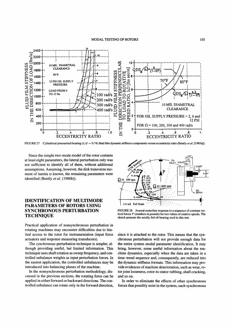
ECCENTCITY TIOFIGURE 27 Cylindrical pressurized bearing (e/d 0.74) fluid film dynamic stiffness components versus eccentricity ratio (Bently et al. [1985a]).
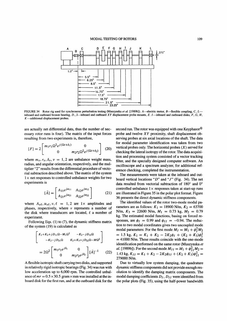
Since the simple two-mode model of the rotor containsat least eight parameters, the lateral perturbation only wasnot sufficient to identify all of them, without additionalassumptions. Assuming, however, the disk transverse mo-ment of inertia is known, the remaining parameters wereidentified (Bently et al. [1986b]).
IDENTIFICATION OF MULTIMODEPARAMETERS OF ROTORS USINGSYNCHRONOUS PERTURBATIONTECHNIQUE
Practical application of nonsynchronous perturbation inrotating machines may encounter difficulties due to lim-ited access to the rotor for instrumentation (input forceactuators and response measuring transducers).The synchronous perturbation technique is simpler, al-
though providing useful, but limited information. Thistechnique uses shaft rotation as sweep frequency, and con-trolled unbalance weights as input perturbation forces. Inthe easiest application, the controlled unbalances may beintroduced into balancing planes of the machine.
In the nonsynchronous perturbation methodology, dis-cussed in the previous sections, the rotating force can beapplied in either forward or backward directions. The con-trolled unbalance can rotate only in the forward direction,
FIGURE 28 Journal centerline response to a sequence of constant ver-tical forces P (numbers in pounds) for two values ofrotative speeds. Thesketch presents the axially fed oil bearing used in this test.
since it is attached to the rotor. This means that the syn-chronous perturbation will not provide enough data forthe entire system modal parameter identification. It maybring, however, some useful information about the ma-chine dynamics, especially when the data are taken in atime-trend sequence and, consequently, are reduced intothe dynamic stiffness formats. This information may pro-vide evidences of machine deterioration, such as wear, ro-torjoint looseness, rotor-to-stator rubbing, shaft cracking,and so on.
In order to eliminate the effects of other synchronousforces that possibly exist in the system, each synchronous
(a)
106
tAft ROTOR
NATURALFREQUENCY
A. MUSZYNSKA
(b)
fl 3500 rpmoil 2 psiecco= 0%fl.t 4100rpm
.6-
.2
0 .2
Pressure 1.22 psi
ECCENTRICITY OF JOURNAL POSITION
(c)
0.4
0.3’
0.2.
0.1-
RADIAL CLEARANCE 6.8 MILS0.173 10-3m
SHAFT KADIUS 0.0254mOIL TI0TEMPERATURE 20*eOIL SUPPLY PRESSURE 10 psi
0.2 0.4
’ 2000 rpm
FLOW COLLAPSES
0.6 0.8SHAFT ECCENTRICITY RATIO,
\\\\\\\
\\\\,,,\
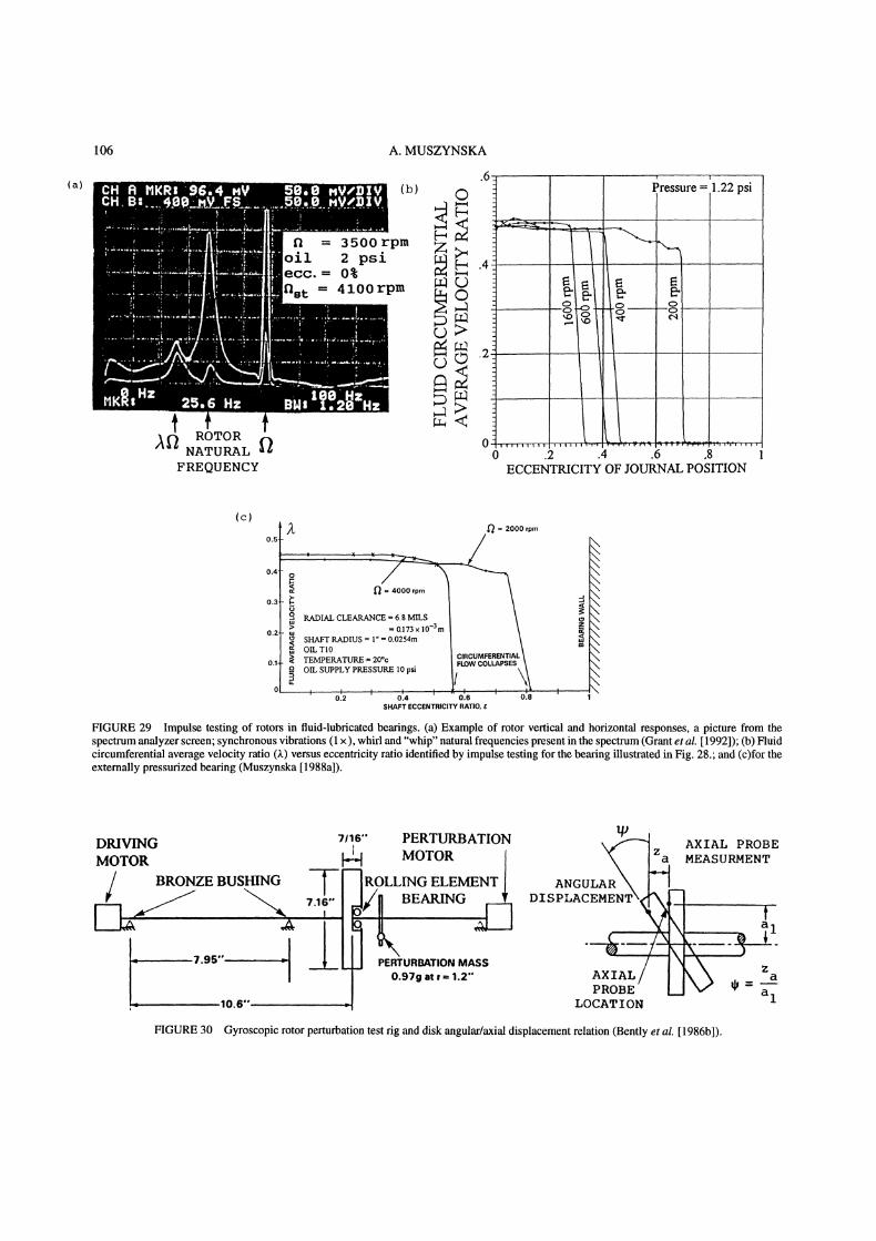
FIGURE 29 Impulse testing of rotors in fluid-lubricated beatings. (a) Example of rotor vertical and horizontal responses, a picture from thespectrum analyzer screen; synchronous vibrations (1 x), whirl and "whip" natural frequencies present in the spectrum (Grant et al. 1992]); (b) Fluidcircumferential average velocity ratio (,k) versus eccentricity ratio identified by impulse testing for the bearing illustrated in Fig. 28.; and (c)for theexternally pressurized bearing (Muszynska 1988a]).
7t,s" PERTURBATION t/)\x,’-’ AXIAL PROBEDRIVINGMOTOR MOTOR AR Za MEASURMENT
/ BRONZE BUSHING TE1ROLLING ELEMENT r ANGUL, !! #’
I ?.95" PERTURBATIONat ,..1.2.. AXIAl"/-IXPROBRX/ ""
’1:-za-a
;= I0.6’" , LOCATION 1
FIGURE 30 Gyroscopic rotor perturbation test rig and disk angular/axial displacement relation (Bently et al. [1986b]).

MODAL TESTING OF ROTORS 107

108 A. MUSZYNSKA
-10000
,8000 EXPERIMENTAL DATA
FIRST FORWARD MODE
SPEED [RPM]
’I2000 3000 4000 5000 6000 7000 8000
FIRST BACKWARD MODE
--6000
-4000
-2000
mO-1000
---2000
-4000
,-6000
..r’" SECOND BACKWARD MODE
--100--12000
FIGURE 32 Gyroscopic rotor natural frequencies versus rotative speed obtained by nonsynchronous perturbation testing. The second forwardmode occurs in the higher range of frequencies (Bently et al. 1986b]).
/ K1 K K /
I 2FIGURE 33 Two-mode rotor model.
perturbation test is performed twice. In the first start-uptest the perturbation controlled weight is introduced to thebalancing plane at certain angle ;. In the second run, thesame controlled weight is moved into + 180 angularlocation at the same radius. The x responses from thesetwo runs are then vectorially subtracted, through the entirerotative frequency range. This eliminates the possible un-known 1 x components. The resulting differential data arethen used for the system identification. An example of thesynchronous perturbation application for two-mode rotoridentification is outlined later in this section (Muszynska1986, 1989b]).Two-mode and, generally, coupled multimode ap-
proach, offer several advantages in comparison with theclassical identification of separate mode parameters. Themultimode identification provides parameters which moreclosely represent the structure parameters, and thus de-
scribe the system more adequately. The identification al-lows locating of the physical position of specific parame-ters most responsible for given modes. This, for instance,makes system modifications more efficient, especiallywhen nonlinear modifications are considered. An exampleofformal transformation ofmodal variables to multi-modemodal coordinates is given at the end of this section.The two-lateral-mode model of an isotropic rotor,
the subject of synchronous perturbation, is as follows(Fig. 33):
0 M2 2 -D21 D22 2
q-K2 K2 -k- K3 z2
where My, Dye, Kv, v, e 1, 2 are rotor multimodemodal masses, damping coefficients, and stiffnesses, re-spectively. Note that they represent partial modal param-eters of the two-mode rotor. [F] is the controlled syn-chronous perturbation force matrix. Theperturbation forceis applied at the first disk location in the first experiment,and at the second disk location in the second experiment(the forces and responses in the identification equations
MODAL TESTING OF ROTORS 109
A C D E F G H j K L
FIGURE 34 Rotor rig used for synchronous perturbation testing (Muszynska et al. [1989b]). A---electric motor, B--flexible coupling, C, L--inboard and outboard bronze bearing, D., Jminboard and outboard XY displacement probe mounts, E. Iminboard and outboard disks, F, G, H,Kmadditional displacement probes.
are actually net differential data, thus the number of nec-essary rotor runs is four). The matrix of the input forcesresulting from two experiments is, therefore,
Imlrl2eJ(2t+l) O l[F] 2 (20)0 m2r222ej(rat+62)
where my, rv, ;v, v 1, 2 are unbalance weight mass,radius, and angular orientation, respectively, and the mul-tiplier "2" results from the differential procedure of 7ecto-rial subtraction described above. The matrix of the system1 net responses to controlled unbalance weights for twoexperiments is
A21eJt21 A22eJt22where Ave, otve, v, e 1, 2 are 1 amplitudes andphases, respectively, where v represents a number ofthe disk where transducers are located, e a number ofexperiment.
Following Eqs. (1) to (7), the dynamic stiffness matrixof the system (19) is calculated as
KI+K2WjDll-MI -K2-jD12
-K2-jD21 KE+K3+jD2292-MK22
2f22 (22)0 tn2r2eja2
[]-1
A flexible isotropic shaft carrying two disks, and supportedin relatively rigid isotropic bearings (Fig. 34) was run withlow acceleration up to 6,000 rpm. The controlled unbal-ance ofmr 0.5 x 30.5 gram xmmwas installed at the in-board disk for the first run, and at the outboard disk for the
second run. The rotor was equipped with one Keyphasor(R)
probe and twelve XY proximity, shaft displacement ob-serving probes at six axial locations of the shaft. The datafor modal parameter identification was taken from twovertical probes only. The horizontal probes (X) served forchecking the lateral isotropy ofthe rotor. The data acquisi-tion and processing system consisted of a vector trackingfilter, and the specially designed computer software. Anoscilloscope and a spectrum analyzer, for additional ref-erence checking, completed the instrumentation.The measurements were taken at the inboard and out-
board vertical locations "D" and "J" (Fig. 34). The netdata resulted from vectorial subtraction of 180 and 0controlled unbalance responses taken at start-up runsare illustrated in Figure 35 in the polar plot format. Figure36 presents the direct dynamic stiffness components.The identified values of the rotor two-mode modal pa-
rameters are as follows: K1 18900 N/m, K2 63700N/m, K3 22600 N/m, M1 0.73 kg, M2 0.79kg. The estimated modal functions, basing on forced re-sponses, are ql 0.99 and Ckll -0.94. The reduc-tion to two modal coordinates gives two uncoupled modemodal parameters: For the first mode MI M1 + t#/2M2
1.5 kg, K1 K + g2 2g2qbl + (g2 + g3)l241000 N/m. These results coincide with the one-mode
identification performed on the same rotor (Muszynska etal. 1989b]). For the second mode MI1 M1 + 49211M21.43 kg, KII K1 + K2 2Kzqbll Jr (K2 -}- K3)qb21i279000 N/m.Due to virtually low system damping, the quadrature
dynamic stiffness components did not provide enough res-olution to identify the damping matrix components. Themodal damping coefficients DI, OlI were identified fromthe polar plots (Fig. 35), using the half-power bandwidth

110 A. MUSZYNSKA
a)INBOARD
.i.,"" J(ll /
"i /
Alle " ;" 2:./. ;\ /iz:a., ,
:. .-,...." ,. /.42;,r .,;.’... :..\.X;;7
\ t!l Zg
" ’t,. <" < //. .1 OSO/...,. r .... H. :7./. _y,-.
"---’2 N:...:..:<. .’. ., ...,.. ..:...:./ / x N
-3 -2 -1 0 1 2 3LITE [mV pp x 10]
b)
OUTBOAKD
c)
INBOARD
e3C12.,. ../...i12 :’,
,t’,,_)-.,’. T ..,:..---,,tGG9
:.. .,:.. ::,,.:. .,.:... .,..", C’
" 4’""l ,.".1 t ....,: ...,5
". ".t.. .... ..’.3,.t..L.
i/: j
<..2 :..:..-4 -2 0 2 4
LITE [mV pp x I0]d)OO....;.
:..,., \ j 0t. / .,.,,e ,, j 0t. 22 "7’i.A2le21
;": :’"(/ A22ej, /: /,. i"...--.,. .;Z.... "..,... --,*Tl,"7 -"1 N \" Im--,,’’’4 II$,’N.._..._ /
" ,,.,., : ""..,:<,./,.....’x N ,4-,.,#;t."l ,. .N.4 L$0..: \’ \ ,t ,-t’;’j /. \
klfil3 "./, .,, \ \.;.... b %,oo i.:-!:" i.;;..._ ">_T :., _.,
,’....’.?I ,’.... ,,", ... :,.....:’7. ::,... .,(’:,’,,, .: .,.
,t:z...: ,tl:.-K-"./.,-I-,’%2.-,.,.-- "’ \ \ :’.. /: ."
:," 2 I i’ \ ,:\’:": ’"""1-""" \:" -i / !’, :.,
/ ...: ".:., ;...,,,:, ,:\\ \ \
:i ’:, ..i ’ X :/".. [.., :.....’,,:
-]3" L ;i"" 0 1 2 3 -4 -2 0 2 4AMPLITUDE [mV pp x 10] AMPLITUDE [mV pp x 1 0]
FIGURE 35 Matrix of polar plots of the rotor net synchronous response to controlled unbalance. (a), (b) unbalance at inboard disk, measurements
by inboard and outboard probes, respectively, (c), (d) unbalance at outbord disk, measurements by inboard and outboard probes, respectively. Netdata compensated by differential subtraction (Muszynska et al. 1989b]). The modal damping ratios evaluated by the half-power bandwidth method
are ’# 0.030(D# 14.9 kg/s), ’#; 0.032(D## 40.4 kg/s).

MODAL TESTING OF ROTORS 111
(C)
" |:l
..._.., ,,x
../
!r
SQUARED lRad/s x 105ROTATI SPEED
ROTATIVE SPEED SQUARED "/Rad/s x 105.
.5
-1
ROTATIVE SPEED [Rad x 100]
FIGURE 36 Direct dynamic stiffness components: two-mode identification of rotor parameters fl’s are modal correction factors (Muszynska et
at. 1989b]).
method. The coefficients Dye of the initial damping ma-trix D were then calculated basing on the modal functionmatrix qS:
D (bT)-1Dm-1 dp(])I qbll
DI 0 ]Dm0 DII
(23)
where Dm is the diagonal modal damping matrix with ele-ments identified using the half-power bandwidth method.The additional proximity transducers observing the ro-
tor served for evaluation of the modal correction factors,/3. Since the two-mass rotor model (Fig. 33) is a roughapproximation of the rotor behavior, and since the per-turbation unbalance weights, and measuring transducerspractically cannot be installed at antinodal locations, thecollected data carry an error. The additional data takenfrom other transducers allowed for correcting this error
by introducing the modal correction factors/3 into the fi-nal identification algorithms (Muszynska et al. [1989b]).
In many practical cases the limited access for installinginstrumentation on a rotating machine prevents one fromidentifying the exact modal parameters. Very often, how-ever, there is no need for accurate values of these param-eters. Their approximate values obtained from regularlycollected synchronous data (without modal correction fac-tors/3, and possible nonlinearity, and/or lateral anisotropytaken into account) represent valuable information on themachine dynamics. These values acquired in a time-trendformat during the machine operation, and showing succes-sive changes in particular dynamic stiffness components,will help in diagnosing the machine state, and in identi-fying the malfunction area. In addition to Bode and polarplot formats for filtered x vibration data reduction, theobserved dynamic stiffness formats, which use the sameraw data, provide invaluable information.
Synchronous perturbation testing is practically alwaysdone on any rotating machinery during balancing rou-tines. The valuable dynamic stiffness data are, however,seldom appreciated, sorted out, and stored. The proce-dure, called here "synchronous perturbation technique,"is performed during routine calibration weight balancing.
112 A. MUSZYNSKA
The 1 x response vectors during any transient start-up orshutdown should be stored, and then processed into thedynamic stiffness format versus f2, from which the ob-served dynamic stiffness components, mass, stiffness, anddamping, can be evaluated. Ifbalancing is performed onlyat one speed, the observed dynamic stiffness will providediscrete values only.
This section will be completed with a discussionon the development of the multi-mode modal models(Muszynska, 1994]) The most often used models of me-chanical structures are based on finite element grids. Inrotor modeling the transfer matrix method is also used.One of the final results of these models is a set of the sys-tem natural frequencies wv, v 2n and a set ofcorresponding modal functions.The uncoupled modal variables, associated with the nat-
ural frequencies, have very little immediate correlation tothe physical and geometric parameters of the system. Theidea of multi-mode modeling originated from the useful-ness of better correspondence of modal masses and stiff-nesses to the physical system masses (such as massivedisks on a rotor) and stiffnesses (such as provided by rel-atively slim shafts). The multi-mode model is built fromthe modal model. An example of its formal derivation forthe case of rotor/bearing system is presented below.The modal model obtained, for instance, from the finite
element method, and possibly reduced to n modes, is asfollows:
[Mm][5] + [Kml[x] 0
following form:
[)] + {T diag (w2 COn2)}[y] 0 (26)
It is required that the matrix in parentheses of Eq. (26)have symmetric tridiagonal form. This condition providesadditional (n2 3n + 2)/2 equations:
nweeeu 0 for [/z v[ >e=l
The total number of obtained equations is n2 n + 1, thusn of the unknown elements e remain arbitrary. Anadditional condition, which assures that the off-diagonalelements of the matrix {. in Eq. (26) are negative, shouldbe used:
n
Ewe2ezez+l < 0 for /z 1 n 1e=l
Some complementary conditions regarding the choiceof matrix should come from the comparison of modaldeflection lines of the original model and the transformedmodel (26). Here there is a place for an application ofoptimization techniques.
PERTURBATION TESTING REVEALSLATERAL-TORSIONAL MODE CROSSCOUPLING IN ROTORS
or[] + diag(wl COn)[x] 0 (24)
where Ix] is an (n 1) rotor lateral displacement vectorand [Mm], [Km] are modal mass and stiffness diagonalmatrices. Assume that the new multi-mode modal modelof the rotor consists ofn masses and n + stiffnesses con-necting the masses in a chain manner. An example of suchmodel is illustrated in Figure 33. A linear transformationx y is applied to Eq. (24), with the condition thatthe transformed mass matrix remains diagonal, and thestiffness matrix is symmetric tridiagonal. The first con-dition imposes the orthogonality of the (n n) matrix
n
/x, v n (25)
where tzv is the Kronecker’s delta. The condition (25)results in n(n + 1)/2 equations for n: unknown elementsof the matrix . The transformed Eq. (24) will have the
The nonsynchronous sweep frequency lateral perturba-tion technique has been used to investigate the lateral-torsional cross coupling due to shaft anisotropy (Bently etal. [1991]). The rotor of the experimental rig was drivenby a synchronous electric motor, connected through a lat-erally flexible, torsionally rigid coupling. In order to sim-ulate anisotropy of the shaft, a part of the shaft at mid-spanwas machined to produce two flats. The shaft carried twodisks, with 36 gear teeth on each of them. The opticalpickups observed the disk gear tooth passing frequencies.The data were then processed through a torsional signalconditioner to obtain the dynamic twist (torsional vibra-tions) of the shaft between two disks. The shaft lateralvibrations were observed by two sets of two proximityprobes in XY configuration. The nonsynchronous pertur-bation unbalanced disk driven by a separate motor wasattached through a rolling element bearing at the shaftmid-span.The lateral response of the shaft to the nonsynchronous
perturbation, presented in a form of the spectrum cas-cade plot (Fig. 37), exhibited significant amounts of the

MODAL TESTING OF ROTORS 113
f 1000 rpm-6
Z2
0 2 4 6FREQUENCY [kepm]
10 12
FIGURE 37 Spectrum cascade of the rotor vertical response to lateral backward rotating force nonsynchronous perturbation (Bently et al. [1991]"Muszynska et al. [1992]).
0[..., 0 2"1 ’" ’"’’64
PERTURBATION FREQUENCY, o[kcpm]Ix
4 6 8 10 12FREQUENCY" [kcpm]
FIGURE 38 Overall amplitude versus perturbation frequency and spectrum cascade of the anisotropic rotor torsional response to lateral backwardnonsynchronous perturbation (Bently et al. 1991 ]; Muszynska et al. 1992]). vt torsional natural frequency.
frequency difference components: 09 , o9 2, and209 2 (Bently et al. [1991]; Muszynska et al. [1992]).The existence of these components is due to the shaftanisotropy, and can be used for its identification. The rotortorsional responses are presented in the form of overall vi-bration amplitude versus perturbation frequency (Fig. 38).
They exhibited high amplitudes at the excitation frequencyequal to the first torsional natural frequency vt. The lat-eral/torsional coupling is related to the rotor residual un-balance. The other peaks of the torsional vibrations occurwhen the linear combinations of frequencies o9 and f2 areequal to the torsional natural frequency vt and the half of
114 A. MUSZYNSKA
it (vt/2). These effects are due to the asymmetry of theshaft plus radial sideload, and could also be further usedfor identification of the shaft anisotropy, such as could begenerated by a propagating transversal crack on the shaft.
z=x+jyZr
Greek letters
rotor lateral displacement in stationary coordinatesrotor lateral displacement in rotating coordinates
FINAL REMARKS
The sweep frequency nonsynchronous circular input forceperturbation testing of rotors proved to be very powerfuland efficient, producing a number of results which hadnot been known. The most important among them are: 1)solid/fluid interaction modes of rotors rotating in fluid en-vironment; 2) identification of the more adequate modelof fluid dynamic forces in lightly loaded bearings and inseals; and 3) multimode parameter identification of ro-tor/bearing/seal systems.The nonsynchronous perturbation testing should soon
be used in the routing testing of rotating machines, atfirst, at least, on the prototype stage. The results couldprovide invaluable information on fluid interaction ef-fects on the rotor, in order to assess the stability marginsfrom fluid whirl, whip, rotating stall, surge, and evaluateother properties of rotating machinery. Less demandingsynchronous perturbation testing (known as "unbalancetesting"), which is now widely performed on machines,should be accompanied by appropriate data acquisition inorder to extract information on "observed dynamic stiff-ness." This invaluable information will greatly assist infurthering machine malfunction diagnostics by using vi-bration monitoring.
/, tr modal correction factorse eccentricity ratio( damping ratior/ fluid dynamic viscosityx complex dynamic stiffness. fluid circumferential average velocity ratiov natural frequency (torsional mode)4 modal functionp transformation matrix; also: angular displacement
coordinateo9 perturbation frequencyf2 rotative speedfZST instability onset
Subscripts
b bearingd diskm modaln number of measurement planes and number of
experimentsp measurement axial location, p n; also:
"perturbation"q displacement in "x" direction (q 1) or "y"
direction (q 2)r perturbation force axial location r n; also:
"radial"s perturbation forward (s 1)or backward (s 2);
also: "shaft"; also: "steady state"tangential; also: "torsional"
/z, v, e, n integers
References
Nomenclature
dDDsDDS, QDSF
K, K1, K2, K3Ko
m, r,
MMfpP,y
response amplitude and phase, respectivelybearing diameterfluid radial damping at zero eccentricityrotor modal dampingdirect and quadrature dynamic stiffness, respectivelyforce amplitude; also: fluid force
transfer functionrotor modal stiffnessesfluid radial stiffness at zero eccentricitybearing lengthunbalance mass, radius, and angular orientation,respectivelyrotor modal massfluid inertia effectpressureamplitude and angular orientation of the constantradial force used in steady-state load teststimetemperaturerotor displacements in horizontal and verticaldirections, respectively
Adams, M. L., Yang, T., and Pace, S. E., 1988, May. A Seal TestFacility for the Measurement of Isotropic and Anisotropic LinearRotordynamic Characteristics, Rotordynamic Instability Problems inHigh-Performance Turbomachinery, The Fifth Texas A&M Univer-sity Workshop, NASA CP3026, College Station, TX.
Adkins, D. R., and Brennen, C. E., 1986. Origins of HydrodynamicForces on Centrifugal Pump Impellers, Rotordynamic InstabilityProblems in High-Performance Turbomachinery, The Fourth TexasA&M University Workshop, NASA CP2443, College Station, TX.
Andrews, R. P., 1985. Rotor-Bearing Dynamic Analysis by StructuralDecoupling, Proceedings o.f the 3rd International Modal AnalysisConference, Orlando, FL.
Bently, D. E., and Bosmans, R. F., 1979. Oil Whirl Resonance, Funda-mentals of the Design ofFluid Film Bearings, Published by ASME.
Bently, D. E., and Muszynska, A., 1982a. Stability Evaluation of Ro-tor/Bearing System of Perturbation Tests, Rotor Dynamic InstabilityProblems in High Performance Turbomachinery. The Second Work-shop at Texas A&M University, NASA CP2250, College Station, TX.
Bently, D. E., and Muszynska, A., 1982b. Oil Whirl Identification byPerturbation Test, Advances in Computer-Aided Bearing Design. 82-72978, ASME/ASLE Lubrication Conference, Washington, D.C.
Bently, D. E., and Muszynska, A., 1983. Perturbation Tests of Bear-ing/Seal of Evaluation of Dynamic Coefficients, Symposium on Rotor
MODAL TESTING OF ROTORS 115
Dynamical Instability, Summer Annual Conference ofthe ASME Ap-plied Mechanics Division, AMDnVol. 55, Houston, TX.
Bently, D. E., and Muszynska, A., 1984. The Dynamic Stiffness Charac-teristics ofHigh Eccentricity Ratio Bearings and Seals by PerturbationTesting, Rotordynamic Instability Problems in High Performance Tur-bomachinery, The Third Workshop at Texas A&M University, NASACP2338, College Station, TX.
Bently, D. E., and Muszynska, A., 1985a. Identification of Beating andSeal Dynamic Stiffness Parameters by Steady-State Load and SqueezeFilm Tests, Proeeding ofBRDRCSymposium on Instability in RotatingMachinery, NASA CP2409, Carson City, NV.
Bently, D. E., and Muszynska, A., 1985b. Measurement ofRotor SystemDynamic Stiffness by Perturbation Testing, Proceedings ofBRDRCSymposium on Instability in Rotating Machinery, NASA CP2409, Car-son City, NV.
Bently, D. E., and Muszynska, A., 1985c. Perturbation Study of Ro-tor/Bearing System: Identification of the Oil Whirl and Oil WhipResonances, Proceedings of the Tenth Biennial ASME Design En-gineering Division Conference on Mechanical Vibration and Noise,85-DET-142, Cincinnati, OH.
Bently, D. E., and Muszynska, A, 1986a. Modal Testing and Parame-ter Identification of Rotating Shaft/fluid Lubricated Bearing System,Proceedings ofthe 4th International ModalAnalysis Conference, LosAngeles, CA.
Bently, D. E., Muszynska, A., and Olas, A., 1986b. Identification ofthe Modal Parameters by Perturbation Testing of a Rotor with StrongGyroscopic Effect, Proceedings of International Conference on Ro-tordynamics, Tokyo, Japan.
Bently, D. E., Muszynska, A., and Franklin, W. D., 1988. Rotor Active’Anti-Swirl’ Control, Transactions ofthe ASME, Journal ofVibration,Acoustics, Stress and Reliability in Design, Vol. 111), No. 2.
Bently, D. E., Muszynska, A., and Goldman, P., 1991. Torsional/Lateral
Vibration Cross Coupling Due to Shaft Asymmetry, BRDRC ReportNo. 1.
Bigret, R., 1984. Elements for the Modal Analysis of Symmetric andNon-Symmetric Transfer Matrix Structures, Proceedings of the 2ndInternational Modal Analysis Conference, Orlando, FL.
Black, H. E, 1969. Effects ofHydraulic Forces in Annular Pressure Sealson the Vibrations of Centrifugal Pump Rotors, Journal ofMechanicalEngineering Science, Vol. II, No. 2.
Black, H. E, and Brown, R. D., 1980. Modal Dynamic Simulation ofFlexible Shafts in Hydrodynamic Bearings, Vibration in Rotating Ma-chinery, Proceedings of IMechE Conference, C266/80, Cambridge,UK.
Black, H. E, and Jensen, D. N., 1970. Dynamic Hybrid Bearing Char-acteristics of Annular Controlled Leakage Seals, Proceedings of In-stitution ofMechanical Engineers, Vol. 184.
Bolotin, V. V., 1963. Nonconservative Problems in the Theory ofElasticStability, Macmillan, New York.
Brennen, C. E., Franz, R., and Arndt, N., 1988. Effects of Cavitationon Rotordynamic Force Matrices, Proceedings of 1988 Conferenceon Advanced Earth-to-Orbit Propulsion Technology, NASA CP3012,Huntsville, AL.
Childs, D. W., 1976. A Modal Transient Simulation Model for FlexibleAsymmetric Rotors, Transactions of the ASME, Journal ofEngineer-ing oflndustry, No. 2.
Childs, D. W., 1986. Force and Moment Rotordynamic Coefficients forPump-Impeller Shround Surfaces, Rotordynamic Instability Problemsin High Performance Turbomachinery, The Fourth Texas A&M Uni-versity Workshop, NASA CP2443, College Station, TX.
Childs, D. W., Elrod, D., and Hale, K., 1988. Annular Honeycomb Seals:Test Results for Leakage and Rotordynamic Coefficients, Compari-
son of Labyrinth and Smooth Configurations, Rotordynamic Instabil-ity Problems in High Performance Turbomachinery, The Fifth TexasA&M University Workshop, NASA CP3026, College Station, TX.
Ewins, D. J., 1984. Modal Testing: Theoryand Practice, Research StudiesPress Ltd., John Wiley & Sons, New York.
Fillod, R., Piranda, J., and Bonnecase, D., 1985. Taking Nonlinearitiesinto Account in Modal Analysis by Curve Fitting of Transfer Func-tion, Proceeding ofthe 3rd International ModalAnalysis Conference,Orlando, FL.
Glasgow, D. A., and Nelson, H. D., 1980. Analysis ofRotor/Bearing Sys-tems Using Component Mode Synthesis, Transactions of the ASME,Journal ofMechanical Design, Vol. 102.
Grant, J. W., 1991. Modelling and Stabilization of a Rotor Supported ina Fluid Beating, M. Sci. Dissertation, University of Nevada, Reno.
Grant, J. W., and Huang, X., 1992. Perturbation Testing of a Ro-tor/Bearing System with Various Stability Thresholds Due to Changesin Lubricant Pressure, BRDRC Report No. 4.
Hull, E. H., 1955. Journal Beating Behavior Under Periodic Loading,G. I. Research Laboratory, Rep. No. 55-RL-1354, Schenectady, NY.
Iwatsubo, T., 1980. Evaluation of Instability Forces of Labyrinth Sealsin Turbines or Compressors, Rotordynamic Instability Problems inHigh-Performance Turbomachinery, The First Texas A&M UniversityWorkshop, NASA CP2133, College Station, TX.
Iwatsubo, T., Sheng, B., and Matsumoto, T., 1988. An ExperimentalStudy on the Static and Dynamic Characteristics of Pump AnnularSeals, Rotordynamic Instability Problems in Hih-Pe. brmance Tur-bomachinery, The Fifth Texas A&M University Workshop, NASACP3026, College Station, TX.
Jery, B., Acosta, A. J., Brennen, C. E., and Caughey, T. K., 1984. Hy-drodynamic Impeller Stiffness, Damping, and Inertia, RotordynamicInstability Problems in High-Perfirmance Turbomachinery, The ThirdTexas A&M University Workshop, NASA CP2338, College Station,TX.
Kanki, H., Fujii, H., Hizume, A., Ichimura, T., and Yamamoto, T., 1986.Solving Nonsynchronous Vibration Problems of Large Rotating Ma-chineries by Exciting Test in Actual Operating Condition, ProceedingsofInternational Conference on Rotordynamics, Tokyo, Japan.
Muszynska,A., 1986. Whirl and Whip--Rotor/Bearing Stability Prob-lems, Journal ofSound and Vibration, Vol. 110, No. 3.
Muszynska, A., 1988a. Improvements in Lightly Loaded Rotor/Bearingand Rotor/Seal Models, Transactions of the ASME, Journal of Vibra-tion, Acoustics, Stress, and Reliability in Design, Vol. 110, No. 2.
Muszynska, A., 1988b. Modal Testing of Rotor/Bearing Systems, In-ternational Journal ofAnalytical and Experimental Modal Analysis,Vol. 1, No. 3.
Muszynska, A., 1988c. Multimode Whirl and Whip in Rotor/BearingSystems, Dynamics ofRotating Machinery, Vol. 2, Hemisphere Pub-lishing, Proceedings of Second International Symposium on Trans-port Phenomena, Dynamics, and Design in Rotating Machinery, Hon-olulu, HI.
Muszynska, A., and Bently, D. E., 1989a. Anti-Swirl ArrangementsPrevent Rotor/Seal Instability, Transactions of the ASME, Journal ofVibration, Acoustics, Stress and Reliability in Design, Vol. 111, No. 2.
Muszynska, A., and Bently, D. E., 1990. Frequency Swept Rotating InputPerturbation Techniques and Identification of the Fluid Force Modelsin Rotor/Bearing/Seal Systems and Fluid Handling Machines, JournalofSound and Vibration, Vol. 143, No. 1.
Muszynska, A., Bently, D. E., Franklin, W. D., and Hayashida, R. D.,1989b. Identification ofModal Parameters of Rotating Systems UsingPerturbation Techniques, Part 2, Proceedings the 12th BiennialASMEConference on Mechanical Vibration and Noise, Montreal, Canada.
116 A. MUSZYNSKA
Muszynska, A., Bently, D. E., Franklin, W. D., Grant, J. W., and Gold-man, P., 1993, April. Applications ofSweep Frequency Rotating ForcePerturbation Methodology in Rotating Machinery for Dynamic Stiff-ness Identification, Transactions ofthe ASME, Journal ofEngineeringfor Gas Turbines and Power, V. 115.
Muszynska, A., 1994, Application ofMulti-Mode Modal Models in Ro-tor Dynamics, ISROMAC-5, Hawai.
Ohashi, H., 1984. Lateral Fluid Forces Acting on a Whirling Centrifu-gal Impeller in Vaneless and Vaned Diffuser, Rotordynamic Instabil-ity Problems in High-Pe.rformance Turbomachinery, The Third TexasA&M University Workshop, NASA CP2338, College Station.
Ohashi, H., Sakurai, A., and Nishihama, L, 1988. Influence ofImpeller and Diffuser Geometries on the Lateral Fluid Forces
of Whirling Centrifugal Impeller, Rotordynamic Instability Prob-lems in High-Performance Turbomachinery, The Fifth TexasA&M University Workshop, NASA CP3026, College Station,TX.
Stone, J. M., and Underwood, F. A., 1947. Load Carrying Capacity ofJournal Beatings, SAE Quartarly Transactions, No. 1.
Sullivan, B. J., 1985. Application of Modal Superposifion in NonlinearRotor Dynamic Analysis, Proceedings ofthe 3rd International ModalAnalysis Conference, Orlando, FL.
Zhang, Q., and Lallement, G., 1985. Experimental Determination ofEigen Solutions of Nonself-Adjoint Mechanical Structures, Pro-ceedings of the 3rd International Modal Analysis Conference,Orlando, FL.

International Journal of
AerospaceEngineeringHindawi Publishing Corporationhttp://www.hindawi.com Volume 2010
RoboticsJournal of
Hindawi Publishing Corporationhttp://www.hindawi.com Volume 2014
Hindawi Publishing Corporationhttp://www.hindawi.com Volume 2014
Active and Passive Electronic Components
Control Scienceand Engineering
Journal of
Hindawi Publishing Corporationhttp://www.hindawi.com Volume 2014
International Journal of
RotatingMachinery
Hindawi Publishing Corporationhttp://www.hindawi.com Volume 2014
Hindawi Publishing Corporation http://www.hindawi.com
Journal ofEngineeringVolume 2014
Submit your manuscripts athttp://www.hindawi.com
VLSI Design
Hindawi Publishing Corporationhttp://www.hindawi.com Volume 2014
Hindawi Publishing Corporationhttp://www.hindawi.com Volume 2014
Shock and Vibration
Hindawi Publishing Corporationhttp://www.hindawi.com Volume 2014
Civil EngineeringAdvances in
Acoustics and VibrationAdvances in
Hindawi Publishing Corporationhttp://www.hindawi.com Volume 2014
Hindawi Publishing Corporationhttp://www.hindawi.com Volume 2014
Electrical and Computer Engineering
Journal of
Advances inOptoElectronics
Hindawi Publishing Corporation http://www.hindawi.com
Volume 2014
The Scientific World JournalHindawi Publishing Corporation http://www.hindawi.com Volume 2014
SensorsJournal of
Hindawi Publishing Corporationhttp://www.hindawi.com Volume 2014
Modelling & Simulation in EngineeringHindawi Publishing Corporation http://www.hindawi.com Volume 2014
Hindawi Publishing Corporationhttp://www.hindawi.com Volume 2014
Chemical EngineeringInternational Journal of Antennas and
Propagation
International Journal of
Hindawi Publishing Corporationhttp://www.hindawi.com Volume 2014
Hindawi Publishing Corporationhttp://www.hindawi.com Volume 2014
Navigation and Observation
International Journal of
Hindawi Publishing Corporationhttp://www.hindawi.com Volume 2014
DistributedSensor Networks
International Journal of