Vibration and Acoustic Test Facility (VATF) - NASA€¦ · A.2 Vibration Capabilities ... The...
71
Vibration and Acoustic Test Facility (VATF) User Test Planning Guide National Aeronautics and Space Administration Lyndon B. Johnson Space Center Houston, Texas 77058
Transcript of Vibration and Acoustic Test Facility (VATF) - NASA€¦ · A.2 Vibration Capabilities ... The...
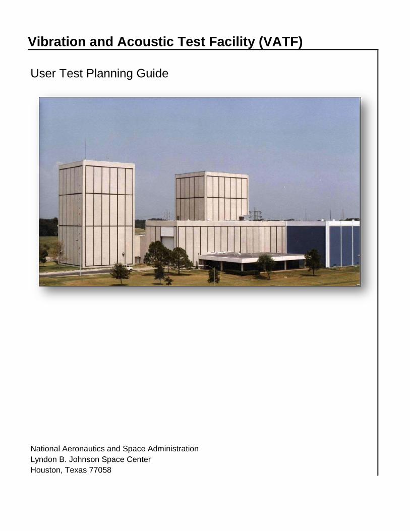
Vibration and Acoustic Test Facility (VATF)
User Test Planning Guide
National Aeronautics and Space Administration Lyndon B. Johnson Space Center Houston, Texas 77058

2
Table of Contents
1.0 Vibration and Acoustic Testing .......................................................................................4
2.0 Facility Layout ...................................................................................................................5
3.0 Safety and Health ..............................................................................................................6
4.0 Test Process Flow ............................................................................................................64.1 Export Controlled and Proprietary Information .................................................................8
4.2 Test Initiation Phase ........................................................................................................9
4.2.1 Test Request ....................................................................................................................... 94.2.2 Schedule and Cost Estimate ................................................................................................ 9
4.3 Test Preparation Phase ................................................................................................. 104.3.1 Test Requirements ............................................................................................................ 104.3.2 Test Documentation ........................................................................................................... 124.3.3 Test Schedule .................................................................................................................... 144.3.4 Test Plan ........................................................................................................................... 144.3.5 Test Article Delivery ........................................................................................................... 144.3.6 Test Readiness Review ..................................................................................................... 15
4.4 Test Execution Phase .................................................................................................... 16
4.4.1 Test Authority .................................................................................................................... 164.4.2 Test Deviations .................................................................................................................. 164.4.3 Facility Equipment ............................................................................................................. 17
4.5 Test Closeout Phase ..................................................................................................... 17
4.5.1 Customer Feedback .......................................................................................................... 17
5.0 Facility Access ................................................................................................................ 18
6.0 Roles and Responsibilities ............................................................................................ 19
Acronyms .................................................................................................................................. 20
Appendices ............................................................................................................................... 22Appendix A VATF Capabilities ............................................................................................. 24
A.1 General Capabilities .......................................................................................................... 24A.2 Vibration Capabilities ......................................................................................................... 25A.3 General Vibration Lab Capabilities ..................................................................................... 27A.4 Spacecraft Vibration Laboratory Capabilities ..................................................................... 29A.5 Vibro-Acoustic Capabilities ................................................................................................ 31A.6 Spacecraft Acoustic Laboratory Capabilities ...................................................................... 32A.7 Sonic Fatigue Laboratory Capabilities ................................................................................ 33

3
A.8 Modal Operations Laboratory Capabilities ......................................................................... 34Appendix B VATF Facility Interfaces ................................................................................... 35
B.1 General Facility Interfaces ................................................................................................. 35B.2 GVL Facility Interfaces ....................................................................................................... 36B.3 SVL Facility Interfaces ....................................................................................................... 38B.3 SVL Facility Interfaces ....................................................................................................... 38B.4 SAL Facility Interfaces ....................................................................................................... 40B.5 SFL Facility Interfaces ....................................................................................................... 43
Appendix C VATF Fixture Interfaces .................................................................................... 45
C.1 GVL Fixture Interfaces ....................................................................................................... 45C.2 SVL Fixture Interfaces ....................................................................................................... 47C.3 SAL Fixture Interfaces ....................................................................................................... 48C.4 SFL Fixture Interfaces ........................................................................................................ 49C.5 MOL Fixture Interfaces ...................................................................................................... 50
Appendix D Sample Test Configurations ............................................................................. 51
D.1 GVL Sample Test Configurations ....................................................................................... 51D.2 SVL Sample Test Configurations ....................................................................................... 52D.3 SAL Sample Test Configurations ....................................................................................... 53D.4 SFL Sample Test Configurations ....................................................................................... 54D.5 MOL Sample Test Configurations ...................................................................................... 55
Appendix E Forms ............................................................................................................... 56
E.1 Test Request Worksheet – VATF ...................................................................................... 56E.2 Test Requirements Worksheet – Example ......................................................................... 61E.3 Test Article Hazard Checklist – VATF ................................................................................ 66E.4 Test Article Hazard Checklist – Example ........................................................................... 68E.5 Laboratory Performance Evaluation ................................................................................... 70
Appendix F Personnel Certification Memorandum – Example ............................................. 71

4
1.0 Vibration and Acoustic Testing The Vibration and Acoustic Test Facility (VATF) at the Johnson Space Center (JSC) is a versatile, dynamic structural test facility located in JSC Building 49 to perform non-hazardous testing. Please consult with the VATF Lab Manager to determine if your test is considered hazardous.
Five laboratories are housed under the VATF:
• General Vibration Laboratory (GVL) • Modal Operations Laboratory (MOL) • Sonic Fatigue Laboratory (SFL) • Spacecraft Acoustic Laboratory (SAL) • Spacecraft Vibration Laboratory (SVL)
These laboratories provide testing for the following:
• Development/Evaluation • Qualification (design verification) Certification • Acceptance (workmanship) Certification • Proto-Flight Certification • Operational or Flight Anomaly Investigations • Trade Studies
The facility can perform a wide range of tests needed to evaluate all aspects of structural dynamics including the following:
• Vibration • Vibro-acoustics • Modal Characteristics • Sound Transmission Loss • Shock
The facility provides the capability to perform testing of both aerospace and non-aerospace hardware. Capabilities include testing of components as small as a few ounces to as large as complete structures or systems. The specific capabilities and features of each laboratory are detailed in Appendix A.
Point of Contact VATF Lab Manager, Peter Fantasia Johnson Space Center 2101 NASA Parkway, Houston, TX 77058 (281) 483-8967 [email protected]

5
2.0 Facility Layout Below are a picture and a diagram of the facility. Details of clearances and interfaces within the facility are located in Appendix B.

6
3.0 Safety and Health Safety is an integral part of the culture at the National Aeronautics and Space Administration (NASA). Management, leadership, and employee involvement from all organizations is critical to the success of NASA′s safety program. In order to ensure personal safety, as well as a safe test environment throughout the process, the Test Requester shall furnish the VATF team with either a Hazard Analysis of the test article and its test support equipment or the information necessary to perform a hazard assessment of the test article and its test support equipment.
Additionally, while visiting JSC, the requester shall follow all facility-specific safety and health requirements. A succinct briefing on the Emergency Action Plan and Emergency Test Procedures will be provided to all personnel prior to the start of the test. The safety briefing will include a review of the VATF safety rules and potential hazards.
4.0 Test Process Flow The flowchart presented below outlines the basic roadmap and significant milestones between the initial test request and delivery of test data. The flow is separated between Test Requester actions and Facility actions, highlighting interactions and inputs between the Test Requester and the Test Director.

7
The test schedule for a particular project in the VATF is dependent on the complexity and scope of the test and on laboratory availability. For time-critical testing, this schedule may be accelerated when feasible or practical.
The structural dynamic tests are typically scheduled on a first-come, first-served basis, unless specific priorities are set by management so that critical hardware testing could override this policy. In the unlikely event of schedule conflicts with another Test Requester, the VATF will negotiate the structural dynamic test schedules on the behalf of all Test Requesters involved.
A detailed schedule shall be developed following a review of the test objectives and requirements. Major milestones are presented below:
Note: The schedule is subject to the complexity of test requirements.

8
A chronological order of tasks that the Test Requester should perform in preparation for a structural dynamic test is presented below. To maintain the integrity of your test schedule, please follow the chronological order of these tasks. The times may be significantly shorter for a test preparation for identical hardware previously tested in the VATF.
Requirement When to Submit Role Test Request Worksheet As soon as desired test dates are known Test Requestor
Requirements and Documentation Shortly after submitting Test Request Test Requestor
Requirements Review Following work authorization Test Requestor Test Director
Test Article Hazard Assessment Submit with Test Request Work Sheet Test Requestor
Test Plan / Procedures Approved prior to Test Readiness Review (TRR) Test Director
Test Assembly Drawings Complete prior to TRR Test Requestor
Test Article/Fixture/Adapter Fit Check Shortly before TRR Test Requestor
Test Director Personnel Certification Memorandum Before or During TRR Test Requestor
No Constraint to Test Documentation
During TRR Test Requestor
4.1 Export Controlled and Proprietary Information The VATF provides for protection of proprietary information and hardware throughout the test process. The Test Requester shall clearly mark all proprietary hardware items and data provided with a notice of restriction on disclosure or usage. The Test Director and VATF team shall safeguard proprietary items from unauthorized use and disclosure and ensure that test articles remain secure within the facility and are properly sequestered. Hardware items shall be returned to the Test Requester or disposed of in accordance with the Test Requester′s instructions at the completion of the test activity.

9
4.2 Test Initiation Phase The test initiation phase establishes the relationship between the Test Requester and the Test Director. The Test Requester shall provide a test request to the Test Director, which will be used to determine test feasibility, to develop an estimated cost, and to establish a preliminary test schedule. An initial requirements review meeting may be necessary in order to discuss the characteristics of the test article, the test approach, or any special considerations for the test. An onsite tour of the VATF is highly recommended for familiarization and to provide an opportunity for an exchange of technical information. Inputs: Test Requester provides test request, identifies Test Article Expert
Activities: Test Director reviews test request to determine test feasibility
Outputs: Facility delivers preliminary test plan, including assumptions; estimated cost; and schedule to Test Requester
4.2.1 Test Request
The test request outlines the test objectives, technical details, and schedule. A blank Test Request Worksheet and a completed example are provided in Appendix E (sections E.1 and E.2, respectively). This worksheet provides VATF with a summary of the requested test requirements and will greatly aid in writing the Test Requirements Document and filling out the Test Request Form (Form 90). It addresses the basic requirements for testing in the VATF. Complete this worksheet and submit it to the Test Director. If you need assistance with this form, contact your Test Director. At a minimum, the test request should include the basic requirements defined in section 4.3.1.
Note: JSC personnel will complete the Test Request Form (Form 90) for external Test Requesters.
4.2.2 Schedule and Cost Estimate
A cost estimate and preliminary test schedule, including major milestones, will be delivered to the Test Requester following receipt of the Test Request Worksheet.

10
4.3 Test Preparation Phase The Detailed Test Plan or Procedure and the Test Schedule are finalized during the test preparation phase. The Test Requester shall provide detailed test requirements and test article documentation to the Test Director. A TRR will be held following approval of the test plan. Inputs: Test Requester provides test requirements and test article documentation (see
section 4.3.2)
Activities: Facility develops structural dynamics test plan/procedure, initiates assembly of facility interface/support structure(s)
Test Requester develops functional test plan/procedure (if applicable), ships/transports test article/equipment to JSC
Outputs: Test Requester approves structural dynamics test plan/procedure and final test schedule
Facility holds TRR
4.3.1 Test Requirements
A complete understanding of test requirements is essential for a successful test. Test requirements must be defined and reviewed so that the VATF team understands the effect of the requirements on test facility preparation. The Test Requester shall provide a detailed list of test requirements, including, but not limited to, the following:
Test Objective
A brief description of the test requirements including, but not limited to:
• Type of test
• Specific test conditions
• Proposed test approach (input excitation)
• Test data requirements (data type, data format, # of channels, sample rate, frequency of analysis, frequency resolution, # of measurements, single or multi-axis measurements, type of analysis)
• Test parameters (G levels, duration, frequency, spectral density, sound pressure level, boundary conditions)
Technical Details
A brief description of the technical details (drawings, sketches, and/or photos are helpful) • including, but not limited to:Test article characteristics [mass, center of gravity (CG),
volume, materials]
• Test configuration [orientation of hardware (x, y, z), active or inert]

11
• Special considerations [hazards, cleanliness, electro-static discharge (ESD), functional tests]
• Handling and storage requirements (method of suspension/support, environment required)
• Test article interfaces (structural, mechanical, electrical)*
• Assembly and installation requirements
• Utility requirements (power, shop air, cooling)
• Existing test article fixture(s) and/or adapter(s)
• Test support hardware being used
• Party responsible for supplying specific equipment
* Details of the facility interfaces are located in Appendix B.
Schedule
Identify the required start date and proposed date for test completion.
Test Article Fixture Requirements
The VATF maintains a limited number of fixtures to support general, non-complex geometries. Please consult with the Test Director prior to designing your fixtures. In some circumstances, dedicated fixtures may not be necessary for your test, due to existing test fixtures or because of innovative mounting techniques. The interface details for existing test fixtures are included in Appendix C. Coordination between the Test Requester and the VATF team should begin very early in the process, as the design and fabrication of test fixtures and/or adapters can be more time consuming than initially anticipated.
For new test fixture requirements, an initial fixture concept and design coordination meeting with the VATF team is highly suggested in order to avoid setup or testing problems. Further consultation with the VATF team should occur during final design of the fixture to ensure that an adequate and workable fixture design has been accomplished. It is highly recommended that the Test Requester make an appointment with the VATF team to perform a fit check on the laboratory test beds following completion of the test fixture. The fit check appointment should be scheduled prior to the TRR.

12
4.3.2 Test Documentation
We can accept documentation through a File Transfer Protocol (FTP) site, by e-mail, or via standard mail.
1. The Test Director will send an invitation to the NASA FTP site to upload and send files.
2. E-mail files to the Test Director or, if the Test Director has not been assigned, to the VATF Laboratory Manager.
3. Mail documentation to the following address: National Aeronautics and Space Administration Attention Peter Fantasia (Mail Code: ES6) Lyndon B. Johnson Space Center 2101 NASA Parkway Houston, Texas 77058
Test Request Worksheet
This worksheet is necessary to ensure that the test plan/procedure meets the Test Requester’s requirements. See section 4.2.1 for details. Completion of this form is the Test Requester’s responsibility. Test Plan/Procedure
A Test Plan or Test Procedure is necessary to ensure that all requirements of the Test Requester and the VATF are achieved in an efficient and reproducible manner. See section 4.3.4 for details. A work authorizing document (WAD), such as Work Orders or a Task Performance Sheet (TPS) (Form 1225C), which contains the required information, may be used by the VATF as a Test Plan or Procedure provided it expedites the execution of the test while maintaining its integrity. If there are any functional tests or specific inspections to be conducted prior to, during, or after a test, the Test Requester will provide those procedures.
Note: The final Test Plan or Procedure should take the form of a step-by-step instruction rather than an e-mail or an engineering memorandum. Drawings
The Test Requester shall provide detailed drawings or precision sketches of the test article, any provided test fixture, and an integrated drawing (test setup) showing the test article, test fixture (indicate axis definition), and representation of the test bed interface, as requested by the VATF. The drawings/sketches should be either isometric or a three-view format when possible. Proper dimensioning is required to define the installation of the test article on the test bed, to define the axis of excitation when applicable, and to locate test article instrumentation. At a minimum, the drawing or precision sketch of the test article, showing axis designations, is required as part of, or as an attachment to, the Test Plan.
13
Material Safety Data Sheets (MSDS)
NASA must ensure that all materials exposed to test environments do not present a hazard to personnel or the test facility. The Test Requester shall deliver to the facility MSDS for materials used in the construction or operation of the test article. The MSDS shall be delivered prior to delivery of the test article. The Test Director will review the materials list for compatibility with the test environment. Integrated Hazard Analysis
The safety of facility personnel, facility equipment, and the test article is imperative to NASA. Potential hazards, material compatibility, and facility interfaces will be reviewed with the facility prior to testing. In certain instances, special precautions must be taken, due to the severity level of these potential hazards. The Test Requester shall complete the Test Article Hazard Checklist [included in Appendix E (section E.3)] or to provide a test article hazard analysis. The checklist should list all hazards associated with the presence and operation of the test article as well as any associated test support equipment. The checklist should be completed from the perspective of the hazards the requester’s hardware presents including any damage to which it is susceptible. A Test Article Hazard Analysis (HA) for the test article and support equipment will be prepared by the Test Director if not provided by the Test Requester.
The VATF will address hazards that the facility and its laboratories may present and will integrate all components relative to the tests into an Integrated Hazard Analysis (IHA) to identify any additional hazards that any component may present to another.
Refer to the Test Article Hazard Checklist to assess what hazards associated with the test article and its support equipment that would result in personal injury or damage to hardware. The Test Article Hazard Checklist must be received to provide adequate time to support completion of the IHA prior to the TRR. Personnel Certification Memorandum
To protect the integrity of the test and test article, a Personnel Certification Memorandum, signed by the manager responsible for the test article, is required to identify all test article personnel with test decision authority and responsibility. Only those test article personnel listed on this memorandum will have the authority to make test decisions with regard to their hardware during the test operations. An example personnel certification memorandum is provided in Appendix F.
Test Request Form (Form 90) – for internal use only
This form is used by JSC as a formal means of requesting a test within JSC. It is the WAD for VATF personnel to provide you support.
14
No Constraint to Test Documentation
Simple documentation, declaring no constraint to test, is required to verify that there are no issues that would invalidate the structural dynamic test. The TRR Summary Sheet (Form 1850) is one version of such documentation for internal Test Requesters.
4.3.3 Test Schedule
A detailed schedule shall be developed by the Test Director and approved by the Test Requester. The schedule shall allow adequate time for review and approval of test requirements, assembly of facility interfaces/structures, and delivery of the test article. The schedule of other tests and maintenance activities will be reviewed and potential conflicts shall be addressed by the Test Director.
4.3.4 Test Plan
A Test Plan or Test Procedure for the structural dynamic test will be prepared by the Test Director, unless one is submitted by the Test Requester. The final test plan or procedure shall be approved by the Test Requester with concurrence from the Test Director. The test plan will be the controlling document, with respect to scope and approach for the test program. The test plan will include, at a minimum, the following:
• Test objectives
• Test article description
• Scope of the tests
• Test environment (such as desired test spectrum) to be imposed on the test article
• Installation of the test article on the test beds
• Safety considerations
• Data requirements
Changes to the test plan that occur after the TRR that result in a major change to the scope of the test or that present new hazards may require a delta TRR.
4.3.5 Test Article Delivery
The test article delivery date will be determined on a case-by-case basis. An agreed-upon delivery date shall be captured as a milestone in the test schedule. The Test Requester shall provide detailed handling instructions prior to delivery of the test article, including handling hazards, cleanliness and storage requirements. The test article shall be secured within the test facility, unless directed to provide another means of storage. An inspection of the test article shall be performed by the Test Director and the Test Article Expert prior to the start of testing. NASA encourages Test Article Expert participation in the test article integration phase to provide immediate feedback on test article handling and on any integration issues that arise.
15
Test articles and support equipment may be temporarily stored in the secure Customer Equipment Storage while not in test. The VATF requests that the Test Requester relocate their equipment if there is a substantial delay (months) between test runs. If document processing of hardware is required for the transportation and delivery of hardware, it is preferred that the hardware be delivered at least 1 business day prior to the test. This substantially reduces the impact to the schedule of the test setup and test.
4.3.6 Test Readiness Review
A TRR will be held to ensure the completion of all necessary facility and test article activities prior to test execution. The TRR will include the following:
• Review of the test plan, test procedures, and other required test documentation • Confirmation of facility and test article readiness • Review of configuration records, including facility interface control documents, pressure
system certification, instrumentation calibration, and materials compatibility • Assurance that controls are in place to mitigate risks or hazards identified in the IHA • Verification that data acquisition and processing functions are in place to adequately
capture all critical data • Confirmation that multimedia coverage is adequate to provide recognition and
assessment of potential test anomalies
Approval to proceed with test operations is granted by the Test Readiness Review Board (TRRB). The Test Director shall ensure that all TRR actions have been accomplished prior to the start of the test. The TRRB shall convene 1 to 5 business days prior to the start of the test. TRRB participants shall include the following: NASA TRRB Chairman Test Article Expert Test Director Systems Safety Engineer Test Safety Officer Quality Engineer – if required by VATF Additional board members can be added on a case-by-case basis, as required by the nature of the test.
An out-of-board TRR may be conducted to maintain efficiency for a series of like test hardware.

16
4.4 Test Execution Phase NASA encourages Test Requester participation in the testing activity. The Test Requester shall provide a Test Article Expert to verify that test setup and execution meet the stated objectives. The Test Article Expert also shall verify test article performance and approve requested test deviations during test operations. Prior to execution of the test, all non-VATF personnel involved in the test will be given a briefing on contigency plans and emergency procedures for the test. Inputs: Approval to begin testing received from TRRB
Activities: Facility completes facility buildup, Detailed Test Procedure
Facility conducts testing activity
Test Requester conducts functional testing activity
Outputs: Test completed
4.4.1 Test Authority
The Test Director has the authority and responsibility to direct the test in accordance with the approved Test Plan and to terminate test activities per test rules when danger is imminent or test control cannot be maintained. The Test Director will ensure that positive actions are taken to halt any steps in the test procedure whenever unsafe or hazardous test conditions arise. The Test Director, with the concurrence of the Test Requester, has the authority to terminate the test when sufficient data has been obtained to meet objectives or when objectives cannot be met. VATF test team personnel will accept directions only from the Test Director.
4.4.2 Test Deviations
Changes to the test procedure shall be approved by the Test Requester with concurrence from the Test Director. Deviations that result in a major change to the scope of the test or that present new hazards may require a delta TRR.

17
4.4.3 Facility Equipment
The facility equipment is dedicated for use by VATF personnel. Prior arrangements can be made with the Test Director for potential use of this equipment by the Test Requester. The duration and type of use will be identified prior to authorization for use. For the safety of all personnel, only authorized personnel may operate facility lifting devices and equipment, including overhead cranes, forklifts, mobile aerial platforms, and pallet jacks. Contact VATF personnel for the operation of any of the VATF’s high bay doors. The customer is encouraged to bring a laptop computer for use during the test. VATF workstations are not available for use by Test Requester personnel. This is necessary to protect the integrity of the facility. The Test Requester should make prior arrangements with the Test Director if a dedicated workstation is required during testing.
Note: Wireless connection is available.
4.5 Test Closeout Phase Data shall be delivered to the Test Requester within the prescribed time established by the agreed-upon test schedule. The Test Requester shall notify the Test Director upon receipt of the data. Acceptance of the test data concludes the test activity. Inputs: Test completed
Activities: Facility ships/transports test article to Test Requester or to next JSC test facility
Test Director delivers data to Test Requester
Outputs: Test Requester accepts data
4.5.1 Customer Feedback
The VATF requests feedback from our customers. Evaluation of the services we provide enables continued improvement to our process. A Lab Performance Evaluation form is included in Appendix E (section E.5). You are encouraged to complete the form and return it to the Test Director, following receipt of the test data. Your participation is greatly appreciated.
18
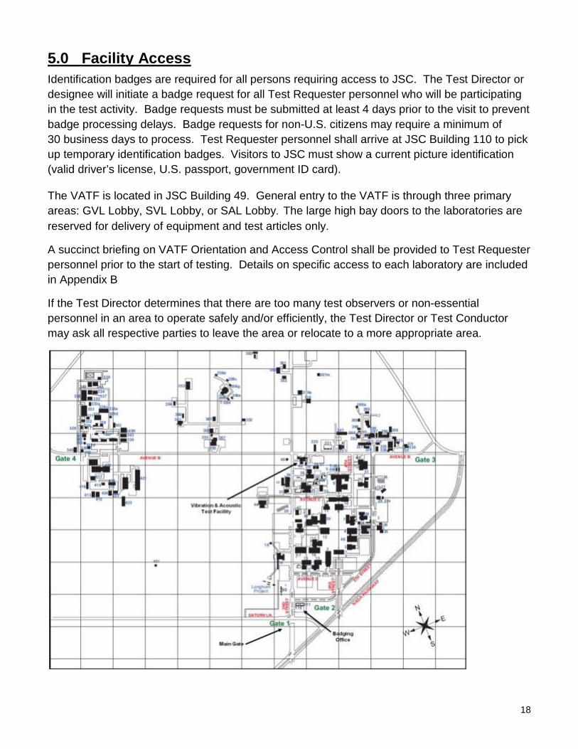
5.0 Facility Access Identification badges are required for all persons requiring access to JSC. The Test Director or designee will initiate a badge request for all Test Requester personnel who will be participating in the test activity. Badge requests must be submitted at least 4 days prior to the visit to prevent badge processing delays. Badge requests for non-U.S. citizens may require a minimum of 30 business days to process. Test Requester personnel shall arrive at JSC Building 110 to pick up temporary identification badges. Visitors to JSC must show a current picture identification (valid driver’s license, U.S. passport, government ID card).
The VATF is located in JSC Building 49. General entry to the VATF is through three primary areas: GVL Lobby, SVL Lobby, or SAL Lobby. The large high bay doors to the laboratories are reserved for delivery of equipment and test articles only.
A succinct briefing on VATF Orientation and Access Control shall be provided to Test Requester personnel prior to the start of testing. Details on specific access to each laboratory are included in Appendix B
If the Test Director determines that there are too many test observers or non-essential personnel in an area to operate safely and/or efficiently, the Test Director or Test Conductor may ask all respective parties to leave the area or relocate to a more appropriate area.

19
6.0 Roles and Responsibilities VATF Lab Manager is responsible for operations of the VATF.
Test Director is responsible for all phases of the test process.
Test Requester is responsible for the test article and for providing a Test Article Expert. The Test Requester is the customer requesting performance of a test activity.
Test Article Expert is responsible for approving the test plan and verifying that test objectives are met. The Test Article Expert is the representative of the Test Requester with thorough knowledge of the test article and how it is to be operated in the test environment.
Test Conductor executes the test in accordance with the approved test plan as assigned under the authority of the Test Director.
Safety Engineer reviews the Test Article Hazard Checklist and Integrated Hazard Analysis for the test facility to identify any additional hazards that could result in injury to personnel. The Safety Engineer concurs that the VATF is safe to operate.
Quality Engineer is responsible for verifying that the test facility is ready for the test by ensuring that all constraints to test have been closed. The Quality Engineer concurs that the engineering integrity of the VATF is maintained. Responsibilities Matrix
Item Test Requester Facility
Test Request Worksheet Create Review and provide assistance as needed
Cost and schedule Approve Create and sign off
Hazards Identify test article hazards Create test article/facility IHA
Test Plan/Procedure (structural dynamic testing) Review and approve Create and sign off
Test Plan/Procedure (pretest and posttest functional) Create and sign off Review
Test Readiness Review Approve Conduct and approve
Test execution
Verify test article performance
Verify that test setup and execution meet objectives
Approve requested deviations
Execute test
Provide test data/results Notify Test Director of data receipt Deliver to Test Requester
Review test data/results Approve
Shipping (to and from facility) Provide instruction Execute per request
20
Acronyms
CCTV Closed-Circuit Television
CG Center of Gravity
CPAS Capsule Parachute Assembly System
dB Decibels
DR Discrepancy Report
ESD Electrostatic Discharge
EVA Extravehicular Activity
FEA Finite Element Analysis
FRF Frequency Response Functions FTP File Transfer Protocol HA Hazard Analysis IHA Integrated Hazard Analysis JSC Johnson Space Center G Gravity GVL General Vibration Laboratory IR Infrared MIMO Multiple Input/Multiple Output MISO Multiple Input/Single Output MOL Modal Operations Laboratory MSDS Material Safety Data Sheets NASA National Aeronautics and Space Administration OASPL Overall Sound Pressure Level ODSA Operating Deflection Shape Analysis OMA Operational Modal Analysis PFR Portable Foot Restraint PKI Public Key Infrastructure psia pounds per square inch absolute psig pounds per square inch gage PWT Progressive-Wave Tube SAL Spacecraft Acoustic Laboratory scfm Standard Cubic Feet per Minute SFL Sonic Fatigue Laboratory

21
SIMO Single Input/Multiple Output SPL Sound Pressure Level SVL Spacecraft Vibration Laboratory TBD To Be Determined TIM Technical Interchange Meeting TPS Task Performance Sheet TRR Test Readiness Review TRRB Test Readiness Review Board UV Ultraviolet VATF Vibration and Acoustic Test Facility WAD Work Authorizing Document

22
Appendices
A. VATF Capabilities A.1 General A.2 Vibration A.3 General Vibration Laboratory A.4 Spacecraft Vibration Laboratory A.5 Vibro-Acoustic A.6 Spacecraft Acoustic Laboratory A.7 Sonic Fatigue Laboratory A.8 Modal Operations Laboratory
B. VATF Facility Interfaces B.1 General B.2 General Vibration Laboratory B.3 Spacecraft Vibration Laboratory B.4 Spacecraft Acoustic Laboratory B.5 Sonic Fatigue Laboratory
C. Test Fixture Interfaces C.1 General Vibration Laboratory C.2 Spacecraft Vibration Laboratory C.3 Spacecraft Acoustic Laboratory C.4 Sonic Fatigue Laboratory C.5 Modal Operations Laboratory
D. Sample Test Configurations D.1 General Vibration Laboratory D.2 Spacecraft Vibration Laboratory D.3 Spacecraft Acoustic Laboratory D.4 Sonic Fatigue Laboratory D.5 Modal Operations Laboratory

23
E. Forms
E.1 Test Request Worksheet E.2 Test Request Worksheet – Example E.3 Test Article Hazard Checklist E.4 Test Article Hazard Checklist – Example E.5 Lab Performance Evaluation
F. Personnel Certification Memorandum – Example

24
Appendix A VATF Capabilities
A.1 General Capabilities
Below are the general capabilities typically found throughout the VATF.
Instrumentation Range
Accelerometers (ICP and Charged)
20 – 5,000 Hz, 1000 G 0 – 400 Hz, DC to 2 G 5 – 3,000 Hz, 5 and 10 G
Strain Gages As needed
Load Cells/Force Transducers
0 – 4,000 lbf 0 – 20,000 lbf 1000 lbf Fz, 500 Fxy
Automated Acoustic Holography Array 58 – 182 dB, 16 – 70,000 Hz
Microphones 90 – 180 dB, 20 – 5000 Hz Sound Intensity Probes 24 – 130 dB, variable frequency
General Facility
• Climate Controlled (shirt sleeve environment)
• Electrostatic Discharge Station
• Critical Lift capability
• Shop Air: 0 – 120 psi
• Power: 20A min
– 100v single phase
– 220v single phase
– 208v 3 phase
– 440v 3 phase
– 480v 3 phase
Other
• Photographic support for testing
• Video support for testing
• Rigging support for testing
• Scaffolding
• Material Handling Equipment
• Wireless Communication available
25
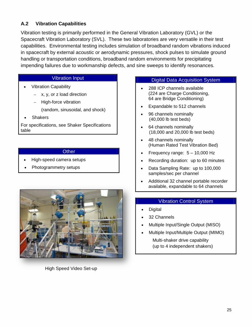
A.2 Vibration Capabilities
Vibration testing is primarily performed in the General Vibration Laboratory (GVL) or the Spacecraft Vibration Laboratory (SVL). These two laboratories are very versatile in their test capabilities. Environmental testing includes simulation of broadband random vibrations induced in spacecraft by external acoustic or aerodynamic pressures, shock pulses to simulate ground handling or transportation conditions, broadband random environments for precipitating impending failures due to workmanship defects, and sine sweeps to identify resonances.
Other • High-speed camera setups
• Photogrammetry setups
Vibration Input
• Vibration Capability
– x, y, or z load direction
– High-force vibration
(random, sinusoidal, and shock)
• Shakers
For specifications, see Shaker Specifications table
Digital Data Acquisition System • 288 ICP channels available
(224 are Charge Conditioning, 64 are Bridge Conditioning)
• Expandable to 512 channels
• 96 channels nominally (40,000 lb test beds)
• 64 channels nominally (18,000 and 20,000 lb test beds)
• 48 channels nominally (Human Rated Test Vibration Bed)
• Frequency range: 5 – 10,000 Hz
• Recording duration: up to 60 minutes
• Data Sampling Rate: up to 100,000 samples/sec per channel
• Additional 32 channel portable recorder available, expandable to 64 channels
Vibration Control System
• Digital
• 32 Channels
• Multiple Input/Single Output (MISO)
• Multiple Input/Multiple Output (MIMO)
Multi-shaker drive capability (up to 4 independent shakers)
High Speed Video Set-up
26
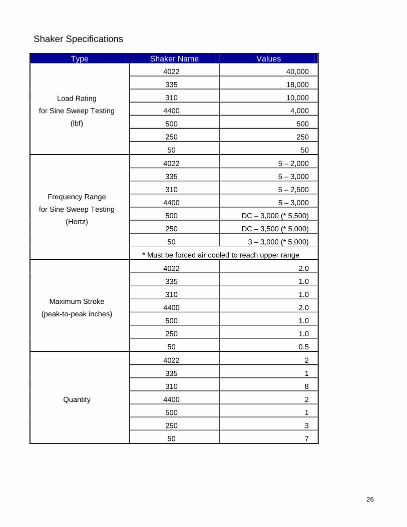
Shaker Specifications
Type Shaker Name Values
Load Rating
for Sine Sweep Testing
(lbf)
4022 40,000
335 18,000
310 10,000
4400 4,000
500 500
250 250
50 50
Frequency Range
for Sine Sweep Testing
(Hertz)
4022 5 – 2,000
335 5 – 3,000
310 5 – 2,500
4400 5 – 3,000
500 DC – 3,000 (* 5,500)
250 DC – 3,500 (* 5,000)
50 3 – 3,000 (* 5,000)
* Must be forced air cooled to reach upper range
Maximum Stroke
(peak-to-peak inches)
4022 2.0
335 1.0
310 1.0
4400 2.0
500 1.0
250 1.0
50 0.5
Quantity
4022 2
335 1
310 8
4400 2
500 1
250 3
50 7

27
A.3 General Vibration Lab Capabilities
The GVL has 5 primary test beds; however, unique test beds can be constructed as necessary to meet a specific test project. Inside the GVL enclosure (removable ceiling panels), the 40,000 lbf shakers for the vertical and horizontal test beds are mounted to seismic floors. Outside the GVL enclosure are two more test beds – an18,000 lbf vertical test bed and a 20,000 lbf horizontal test bed. Combined, these single-axis test beds cover all three orthogonal axes typically tested. The GVL also houses an 8,000 lbf human-rated vibration test bed that is certified to support all levels of Medical Monitoring. The GVL typically provides testing for subsystems and smaller components from as large as an aircraft rudder to as small as a 4 oz heart rate monitor.
The GVL is also capable of measuring vibrations from sources not generated by shakers. These measurements can be made at the VATF or other locations.
Type Values
Bridge Crane
2 Hooks
Hook 1: 5 ton capacity; 30’-7 ¼” hook height
Hook 2: 20 ton capacity; 29’-6 ¾” hook height
Horizontal 40,000 lbf
40,000 lb Horizontal Test Bed 40,000 lb Vertical Test Bed
18,000 lb Vertical Test Bed 20,000 lb Horizontal Test Bed

28
The GVL is developing the following capability in the near future:
• High-Energy Shock Test Capability (beyond range of electromagnetic shakers) • Low-Frequency Vibration Test Capability (<5 Hz) • High-Frequency Vibration Test Capability (up to 10,000 Hz) • Multicelled Closed-Circuit Television (CCTV) System for Each Test Bed (improve
visibility during testing) • 2 to 8 Shakers Configuration with up to 80,000 lb Capacity by Increasing Amplifier
Complement
Consult with the VATF Laboratory Manager for the progress of the development of these future capabilities in this regard. It is likely that some or all of these future capabilities may be established in the timeframe you require one or more of them. Also, if you have a unique application, once again contact the VATF Laboratory Manager. It is possible that the GVL may be able to develop a unique test setup quickly and economically.
Human-Rated Vibration Test Bed

29
A.4 Spacecraft Vibration Laboratory Capabilities
The SVL was specifically designed for vibration testing of large structures and used for Apollo, Skylab, Space Shuttle, and Space Station tests. It provides a vast array of access platforms to the test articles. It was originally built to accommodate vibration testing of the third stage of the Saturn V with the Apollo Command/Service module.
In the past, SVL tests involved high-force, low-frequency (5 to 50 Hertz, generally) excitation of large structural assemblies. Massive test articles can be supported by pneumatic springs and subjected to high-force inputs, which simulate rocket-induced discrete-frequency or random loads with distributed mechanical shakers. The following are typical types of testing functions performed:
• High-Force Vibration (Random) • High-Force Vibration (Sine) • Shock Vibration • Fixed-Base and Free-Free Modal
Type Values
Bridge Crane
2 Hooks
Hook 1: 10 ton capacity; 87’ 10.75” hook height
Hook 2: 20 ton capacity; 83’ 10.75” hook height
Fixed Hoist 75 ton capacity; 93’ hook height
Freight Elevator 4 ton capacity; semiautomatic
Services all but the 6th and 8th floors

30
The SVL also lends itself very well to other large-scale testing beyond structural dynamic testing.
ISS Solar Array Rotary Joint Evaluation and Training Test Bed
Capsule Parachute Assembly System (CPAS) Chute Line Torque Tests

31
Digital Data Acquisition System • 288 ICP channels available
(224 are Charge Conditioning, 64 are Bridge Conditioning)
• Expandable to 512 channels
• 128 channels nominally
• Frequency range: 5 – 10,000 Hz
• Recording duration: up to 60 minutes • Data Sampling Rate: up to
100,000 samples/sec per channel • Additional 32-channel portable recorder
available, expandable to 64 channels
Acoustic Control System
• Digital
• 32 Channels
• Computer-based, 1/3-octave band control based on average of up to 16 microphones
A.5 Vibro-Acoustic Capabilities
Vibro-Acoustic and sound transmission loss testing is primarily performed in the Spacecraft Acoustic Laboratory (SAL) or the Sonic Fatigue Laboratory (SFL). These two laboratories are very versatile in their test capabilities. The noise generation is through the use of compressed air to the high and low frequency modulators, which in turn are coupled to the acoustic horns for generating the acoustic excitation in the Reverberant Chambers and Progressive Wave Tubes (PWTs). Acoustic speakers can also be used as stand-alone acoustic excitation or for driving the acoustic horns. It is possible to retrofit the Noise Generation System with nitrogen.
Noise Generation • Horn cutoff frequency selection
– (20 – 400 Hz) • 20 low-frequency air modulators
– (0 – 500 Hz) • 18 high-frequency air modulators
– (20 – 5000 Hz) • Speakers (10,000 Hz) • Duration of run time at max OASPL is unlimited • Acoustic sound Media: Compressed Dry Air • Air Supply – Digital controlled compressor: 700 hp
– Additional continuous supply of more than 4,000 scfm at 20 psi
Other
• Automated Holographic Array (36 microphones)
• Large Progressive-Wave Tube (~163 dB)
– Max panel size – 6′ x 11′
• Small Progressive-Wave Tube (~165 dB)
– Max panel size – 3′ x 5′
Automated Holographic Array Progressive Wave Tube

32
A.6 Spacecraft Acoustic Laboratory Capabilities
The VATF’s SAL is world class, having the second largest reverberant chamber in the world providing the highest sound intensity and best low-frequency performance available in a large chamber, making it the largest chamber with the potential to produce over 160 dB. The SAL is equipped with a modular and movable ceiling and is designed to accommodate two different ceiling heights (75′ and 32′-8″, respectively).
Type Values
Bridge Crane
2 Hooks
Hook 1: 15 ton capacity; 87’ hook height
Hook 2: 15 ton capacity; 87’ hook height
Fixed Hoist 37 ton capacity; 93’ hook height
Freight Elevator 4 ton capacity; semiautomatic
Services all 6 floors
Test Cells • Reverberant Chamber
• Reverberant Chamber volume: – 137,750 ft3
– 59,875 ft(high ceiling – 75′)
3
• Ceiling can be lowered to ~ 33 ft high (low ceiling – 32′ 8″)
• Sound Pressure Level (SPL) – 152 dB (high ceiling – 75′) – 155 dB (low ceiling – 32′ 8″)
• “Hot Spotting”: 160 dB • Potential SPL to achieve:
– 163 dB (high ceiling – 75′) – 165 dB (low ceiling – 32′ 8″)
• Acoustic Frequency Control Range: – 25 – 10,000 dB; 1/3 octave band
• Lowest octave band with 20 or more modes – 25 Hz (high ceiling – 75′) – 31.5 Hz (low ceiling – 32′ 8″)
• Reverberant Chamber Cutoff Frequency: – 41 Hz high ceiling – 54 Hz low ceiling
• Hemi-Anechoic Chamber (sound transmission loss testing)
• Hemi-Anechoic Chamber volume: – 253.9 ft3
• Hemi-Anechoic Chamber Cutoff Frequency: (free space)
– Projected to be 250 Hz
SAL Reverberant Chamber
SAL Hemi-Anechoic Chamber
33
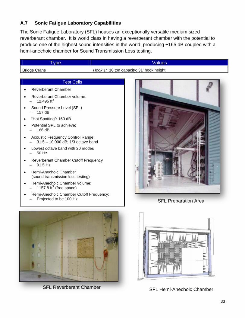
A.7 Sonic Fatigue Laboratory Capabilities
The Sonic Fatigue Laboratory (SFL) houses an exceptionally versatile medium sized reverberant chamber. It is world class in having a reverberant chamber with the potential to produce one of the highest sound intensities in the world, producing +165 dB coupled with a hemi-anechoic chamber for Sound Transmission Loss testing.
Type Values Bridge Crane Hook 1: 10 ton capacity; 31’ hook height
Test Cells • Reverberant Chamber
• Reverberant Chamber volume: – 12,495 ft
• Sound Pressure Level (SPL)
3
– 157 dB • “Hot Spotting”: 160 dB • Potential SPL to achieve:
– 166 dB
• Acoustic Frequency Control Range: – 31.5 – 10,000 dB; 1/3 octave band
• Lowest octave band with 20 modes – 50 Hz
• Reverberant Chamber Cutoff Frequency – 91.5 Hz
• Hemi-Anechoic Chamber (sound transmission loss testing)
• Hemi-Anechoic Chamber volume: – 1157.8 ft3
• Hemi-Anechoic Chamber Cutoff Frequency: (free space)
– Projected to be 100 Hz SFL Preparation Area
SFL Hemi-Anechoic Chamber SFL Reverberant Chamber

34
A.8 Modal Operations Laboratory Capabilities
Modal testing consists of experimentally determining the resonance frequencies, corresponding mode shapes, and damping values for a structure. The MOL houses equipment and space for the setup, acquisition, and analysis of modal data. The test setups, however, are usually in one of the other VATF laboratories. Moveable isolated, seismic masses can be arranged to support massive test articles via air or coil springs, provide great flexibility in shaker locations, and allow easy personnel access to the entire setup. Signal conditioning and data acquisition is accomplished by exciting a test structure with an electro-dynamic shaker or a modally-tuned impact hammer while measuring both the input force and output structural response. By exciting the structure and acquiring Frequency Response Functions (FRF), its modal characteristics can be identified through different curve fitting algorithms. Capability exists for Single Input/Multiple Output (SIMO) and MIMO excitation and outputs.
The MOL is developing, in the very near future, an 80-channel Modal Control and Processing system based on VXI technology. Consult with the VATF Laboratory Manager for the progress of the development of this future capability in this regard. It is likely that this capability may be established within your required timeframe.
Capabilities • Input excitation - flexible
– Sine, random, burst random/chirp, sine on random (shaker driven)
– Impact (impact hammer driven)
– Operational (vibrating) test article
• Shakers – wide array
– up to 500 lb capacity with single or multiple shakers
• Modally tuned impact hammers available in different sizes
• Boundary condition capability - fixed or free
– Large seismic mass bases up to 20,000 lb
– Various Isolation Systems available
– Multiple fixtures available
Data Acquisition/ Modal Control System • Modal Control and Processing system:
– 43 inputs + 5 output channels
• Data Acquisition
– See Appendix A (section A.5)
Modal Analysis • Modal characteristics
– Natural frequencies
– Damping ratios
– Mode shapes
• Mathematical or FEA model correlation
• Operating Deflection Shape Analysis (ODSA)
• Fault detection
• Operational Modal Analysis (OMA)

35
Appendix B VATF Facility Interfaces
B.1 General Facility Interfaces
Consult with the Test Director for quantities and locations of the utilities.
Shop Air 125 psi Electrical Receptacles

36
B.2 GVL Facility Interfaces
The GVL is the central section of the VATF. The available floor space in the GVL High Bay is limited by the presence of pallet racks on the south side, the GVL Sound Enclosure, and several test beds (one of which is the Human-Rated Vibration Test Bed).
Equipment access to the GVL is by a high bay door on the west side. Personnel access is through the GVL and SVL lobbies. Equipment access to the GVL Sound Enclosure is through a set of double doors on the south side of the enclosure. In addition, the roof of the chamber contains removable panels for crane access to the enclosure. Personnel access is via the GVL Control Room.
Available floor space in the GVL Sound Enclosure is limited by the presence of 2 test beds. For utility interfaces, see Appendix B (section B.1).
GVL Facility Details
Plan View of the GVL High Bay
Type Values External Dimensions 58′ 6″ wide x 109′ 8-3/8″ long x 45′ 11″ tall
Available Volume (open) 112’ wide x 64’ deep x 45’ tall
Door Opening 31′ 10″ wide x 39′ 2″ tall
GVL Sound Enclosure
Available Volume 27’ 9” x 36’ 4” x 15’ tall
GVL Sound Enclosure
Equipment Door Opening
6′ wide x 8′ tall

37
Elevation View (West Face) of the GVL High Bay
Elevation View of the West Side GVL High Bay Door

38
B.3 SVL Facility Interfaces
The SVL is the west tower of the VATF. Internally, the tower is subdivided into 9 levels. Each level is defined by a horseshoe-shaped arrangement of flooring (Diamond Tread plating). Moveable platforms, capable of spanning the open part of the tower from east to west, are available for placement on any level, 2 through 9. In addition, shorter platforms are available for installation between moveable platforms from north to south. The platforms are capable of spanning the open area of the tower.
Equipment access to the SVL is by a high bay door on the north side. Personnel access is through the SVL Lobby. An internal stair on the west side of the tower provides access to the second through ninth levels. A semi-automatic freight elevator services all but the 6th and 8th
For utility interfaces, see Appendix B (section B.1).
floors (these floors do not contain any decking, with the exception of the stair landings).
SVL Facility Details
Type Values External Dimensions 61′ 5″ x 61′ 5″ x 106′ 6″ tall
Available Volume (open) 37′ 4″ wide x 47′ 6″ deep x 93’ tall
Door Opening 31′ 10″ wide x 39′ 2″ tall
Floor Levels 9, each level is defined by a horseshoe-shaped arrangement
Platforms
For easy access to test articles
At 15′, 25′, 35′, 45′, 55′, 65′, 75′, and 85′ elevations
Levels 2 through 5, 7, and 9 have flooring
Levels 6 and 8 have flooring at the stair landings
Moveable Platform
37′ 8″ long x 4′ 8.5″ wide x 1′ 9.25″ deep
Capable of spanning the open part of the tower from east to west 10 long, moveable platforms available for placement on any of the eight upper levels Design live load capacity of 100 psf; 12,000 lb concentrated load at mid span Shorter platforms are available for installation between moveable platforms in a north-to-south orientation

39
SVL Plan View
SVL Elevation View

40
B.4 SAL Facility Interfaces
The SAL is the east tower of the VATF. Internally, the tower is subdivided into 6 levels. Each level is defined by a horseshoe-shaped arrangement of flooring (grating) surrounding the reverberation chamber.
Equipment access to the SAL is by a high bay door on the north side, but is limited to the Reverberant Chamber opening. Personnel access is through the SAL Lobby. An internal stair on the south side of the tower provides access to the second through sixth levels. An automatic elevator services floors 2 through 6.
For utility interfaces see Appendix B (section B.1).
SAL Facility Details
Type Values External Dimensions 61′ 5″ x 70′ 9″ x 106′ 6″ tall
Door Opening 31′ 10″ wide x 39′ 2″ tall
Reverberant Chamber
Available Volume
38′ 9.75″ x 47′ 4″ x 75’ tall
(ceiling can be lowered to ~ 33 level’)
Reverberant Chamber Opening 32′ wide x 29′ 5′ tall
Reverberant Chamber
Personnel Door Access
3′ 7″ wide x 8′ 1 ¾″ tall
Hemi-Anechoic Chamber
Available Volume
78″ x 76″ x 75” free space wedge-tip to wedge-tip
Hemi-Anechoic Chamber
Personnel Door Access
3′ 9″ wide x 7′ tall
Floor Levels Tower is divided into six levels, each level is defined by a horseshoe shaped arrangement of flooring surrounding the reverberation chamber at 15’ intervals.
Test Panel Openings 32′ wide x 29′ 5′ tall
70″ wide x 74″ tall
Large “Elephant” Stand
41
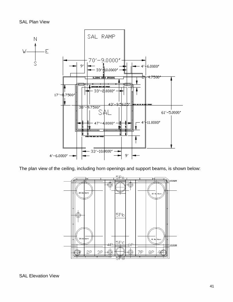
SAL Plan View
The plan view of the ceiling, including horn openings and support beams, is shown below:
SAL Elevation View

42
An elevation view of the high bay door.
43
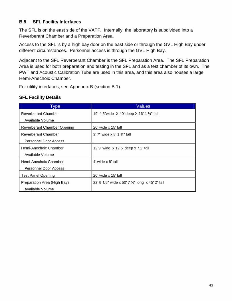
B.5 SFL Facility Interfaces
The SFL is on the east side of the VATF. Internally, the laboratory is subdivided into a Reverberant Chamber and a Preparation Area.
Access to the SFL is by a high bay door on the east side or through the GVL High Bay under different circumstances. Personnel access is through the GVL High Bay.
Adjacent to the SFL Reverberant Chamber is the SFL Preparation Area. The SFL Preparation Area is used for both preparation and testing in the SFL and as a test chamber of its own. The PWT and Acoustic Calibration Tube are used in this area, and this area also houses a large Hemi-Anechoic Chamber.
For utility interfaces, see Appendix B (section B.1).
SFL Facility Details
Type Values Reverberant Chamber
Available Volume
19′-4.5″wide X 40′ deep X 16′-1 ¼″ tall
Reverberant Chamber Opening 20′ wide x 15′ tall
Reverberant Chamber
Personnel Door Access
3′ 7″ wide x 8′ 1 ¾″ tall
Hemi-Anechoic Chamber
Available Volume
12.9’ wide x 12.5’ deep x 7.2’ tall
Hemi-Anechoic Chamber
Personnel Door Access
4′ wide x 8′ tall
Test Panel Opening 20′ wide x 15′ tall
Preparation Area (High Bay)
Available Volume
22′ 8 1/8″ wide x 50′ 7 ¼″ long x 45′ 2″ tall

44
SFL Elevation Views
Elevation View of the East Side SFL Preparation Area High Bay Door
Elevation View of the West Side SFL Preparation Area High Bay Door

45
Appendix C VATF Fixture Interfaces
C.1 GVL Fixture Interfaces
The GVL has various slip tables, expander heads, L-brackets, V-blocks, adapter plates, and universal fixtures to support general, non-complex geometries. Contact the Test Director prior to designing your test fixture. In some circumstances, dedicated fixtures may not be necessary for your test. The VATF can arrange to have test fixtures manufactured to requester specifications. Please contact the Test Director to discuss test article interface requirements.

46
Universal Test Fixtures
V-Blocks
Specifications
Test Bed Head Expander Size Slip Table Size
40,000 lbf Vertical
54″ DIA 40″ DIA 27″ DIA
40,000 lbf Horizontal
60″ x 67.63″
18,000 lbf 32″ DIA 20,000 lbf 48.5″ x 48″ 4,400 lbf 44″ x 44″
47
C.2 SVL Fixture Interfaces
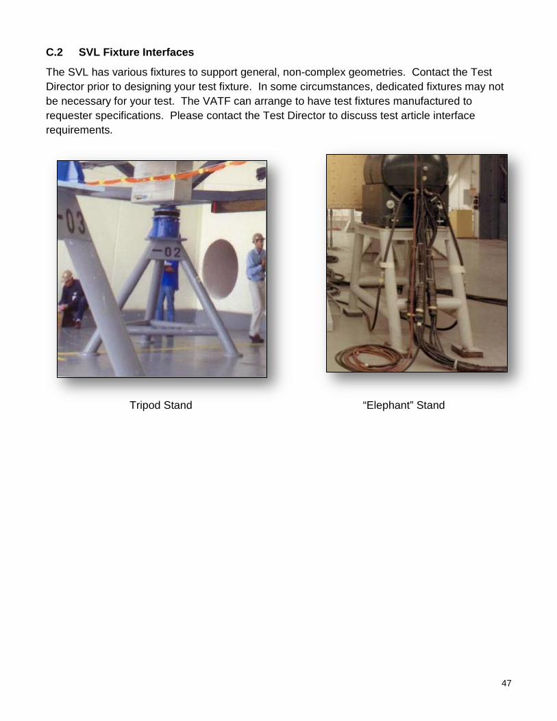
The SVL has various fixtures to support general, non-complex geometries. Contact the Test Director prior to designing your test fixture. In some circumstances, dedicated fixtures may not be necessary for your test. The VATF can arrange to have test fixtures manufactured to requester specifications. Please contact the Test Director to discuss test article interface requirements.
“Elephant” Stand Tripod Stand
48
C.3 SAL Fixture Interfaces
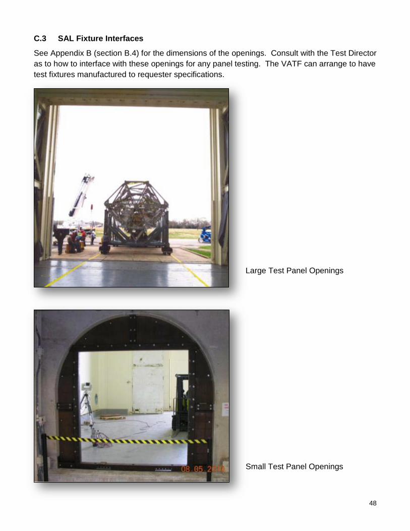
See Appendix B (section B.4) for the dimensions of the openings. Consult with the Test Director as to how to interface with these openings for any panel testing. The VATF can arrange to have test fixtures manufactured to requester specifications.
Small Test Panel Openings
Large Test Panel Openings

49
C.4 SFL Fixture Interfaces
See Appendix B (section B.5) for the dimensions of the openings. Consult with the Test Director as to how to interface with these openings for any panel testing. The VATF can arrange to have test fixtures manufactured to requester specifications.
Removable Test Panels

50
C.5 MOL Fixture Interfaces
The MOL has various fixtures and ballast plates to support general, non-complex geometries. Contact the Test Director prior to designing your test fixture. In some circumstances, dedicated fixtures may not be necessary for your test. The VATF can arrange to have test fixtures manufactured to requester specifications. Please contact the Test Director to discuss test article interface requirements.
“Elephant” House
Modal Tripod
Ballast Plate with Spring Set
51
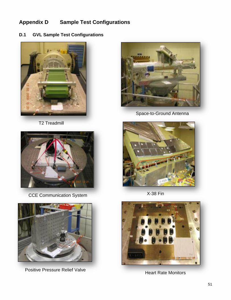
Appendix D Sample Test Configurations
D.1 GVL Sample Test Configurations
Heart Rate Monitors Positive Pressure Relief Valve
T2 Treadmill
X-38 Fin
Space-to-Ground Antenna
CCE Communication System

52
D.2 SVL Sample Test Configurations
Apollo Upper Stage Skylab
53
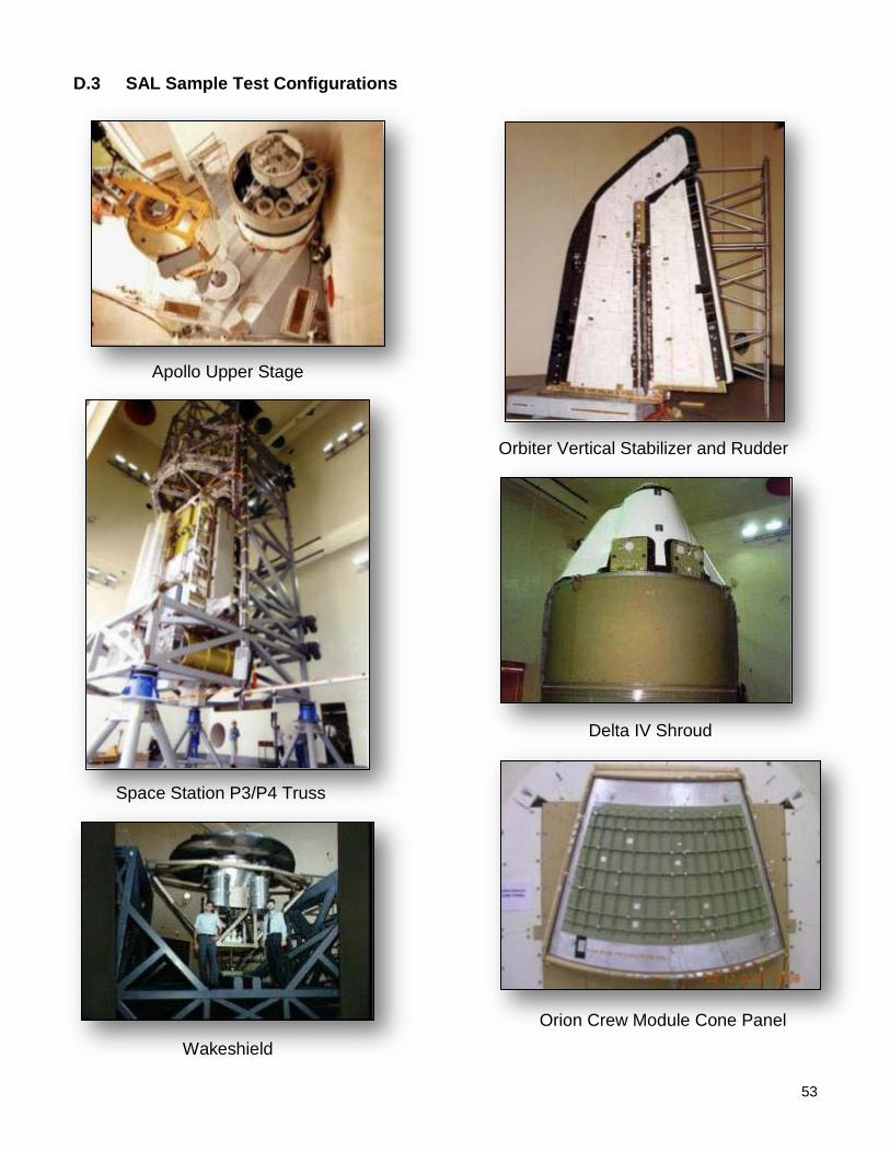
D.3 SAL Sample Test Configurations
Apollo Upper Stage
Wakeshield
Space Station P3/P4 Truss
Delta IV Shroud
Orbiter Vertical Stabilizer and Rudder
Orion Crew Module Cone Panel

54
D.4 SFL Sample Test Configurations
Orbiter Wing Panel Orbiter Wing Panel
Orbiter Nose Cone
55
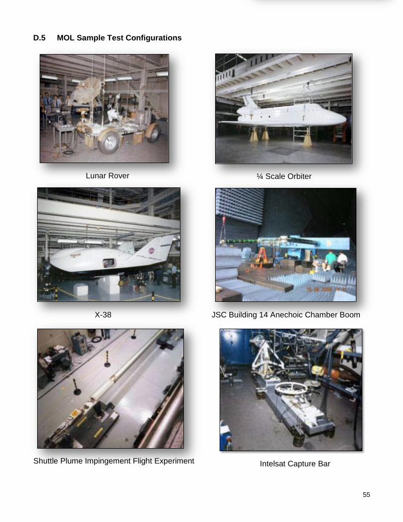
D.5 MOL Sample Test Configurations
Lunar Rover ¼ Scale Orbiter
X-38 JSC Building 14 Anechoic Chamber Boom
Shuttle Plume Impingement Flight Experiment Intelsat Capture Bar
56
Appendix E Forms
E.1 Test Request Worksheet – VATF
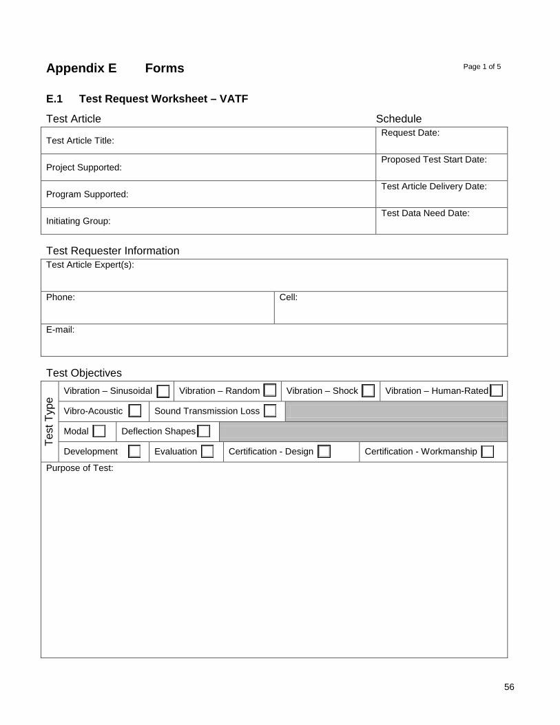
Test Article Schedule
Test Article Title: Request Date:
Project Supported: Proposed Test Start Date:
Program Supported: Test Article Delivery Date:
Initiating Group: Test Data Need Date:
Test Requester Information Test Article Expert(s):
Phone:
Cell:
E-mail:
Test Objectives
Test
Typ
e
Vibration – Sinusoidal Vibration – Random Vibration – Shock Vibration – Human-Rated
Vibro-Acoustic Sound Transmission Loss
Modal Deflection Shapes
Development Evaluation Certification - Design Certification - Workmanship
Purpose of Test:
Page 1 of 5

57
Test Article Test Article Description:
Physical Dimensions (L/W/H):
Weight:
Test Article Interface Test Article Interface Design (Facility or Requester designed, drawings attached, instructions):
Test Fixture (facility stock, facility fabricated, or requester provided):
List materials, instruments, and support hardware supplied by Requester for structural dynamic test:
Test Request Worksheet – VATF Page 2 of 5

58
Test Article Handling Requirements Cleanliness Level:
Controlled Access:
Special Moving/Handling:
Test Environment (Vibration) Complete the Test Environment table below or provide a plot of the test environment to be simulated.
Axis Frequency (Hz): Spectral Density (g2 Tolerance (dB) /Hz) Duration
X
Y
Z
Test Request Worksheet – VATF Page 3 of 5

59
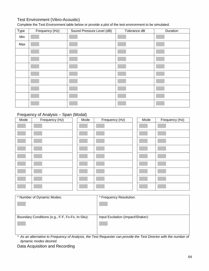
Test Environment (Vibro-Acoustic) Complete the Test Environment table below or provide a plot of the test environment to be simulated.
Type Frequency (Hz): Sound Pressure Level (dB) Tolerance dB Duration
Min
Max
Frequency of Analysis – Span (Modal)
Mode Frequency (Hz) Mode Frequency (Hz) Mode Frequency (Hz)
* Number of Dynamic Modes:
* Frequency Resolution:
Boundary Conditions (e.g., F-F, Fx-Fx, In-Situ):
Input Excitation (Impact/Shaker):
* As an alternative to Frequency of Analysis, the Test Requester can provide the Test Director with the number of dynamic modes desired.
Test Request Worksheet – VATF Page 4 of 5

60
Data Acquisition and Recording Number of Channels: Audio/Video Recording: Y N
Format: Sampling Rates: Photographic Film: Y N
Format: Real-Time Data Processing: Y N
High-Speed/Low-Speed Video: Y N
Format: Recording Speed:
Number Instruments: Photogrammetry: Y N
Accelerometers: Uni-axial: Tri-axial:
Microphones: Load Cells: Time Synchronize Media with Data: Y N
Strain Gages:
Instrumentation List the primary measurements to be made (e.g., Frequency, Spectral Density, FRF, modal damping, mode shape):
Additional Instrumentation and Support Hardware Provided by Test Requester for functional tests:
Other Information List any other information pertinent to the test:
Test Request Worksheet – VATF Page 5 of 5

61
E.2 Test Requirements Worksheet – Example
Test Article Schedule Test Article Title: Widget A Assembly
Date of Request: 1/1/2011
Project Supported: System B
Proposed Test Start Date: 3/1/2011
Program Supported: Vehicle C
Test Article Delivery Date: 2/24/2011
Initiating Group: Company D Inc.
Test Data Need Date: 4/1/2011
Test Requester Information Test Article Expert(s): John Smith
Phone: 555-555-5554
Cell: 555-555-5555
E-mail: [email protected]
Test Objectives
Test
Typ
e
Vibration – Sinusoidal Vibration – Random Vibration – Shock Vibration – Human-Rated
Vibro-Acoustic Sound Transmission Loss
Modal Deflection Shapes
Development Evaluation Certification - Design Certification - Workmanship
Purpose of Test:
Sample Vibration To verify feasibility of Widget A to attached vibration levels and, posttest, completing full functional testing successfully

62
Test Article Test Article Description:
Widget A Assembly – Used to maintain System B
P/N AAA 12345B
S/N 1001 and 1002
Materials: Aluminum and glass.
Physical Dimensions (L/W/H): 38″ x 23″ x 12.5″
Weight: 103.5 lb
Test Article Interface Test Article Interface Design (Facility or Requester designed, drawings attached, instructions):
See attached drawings.
Test Fixture (facility stock, facility fabricated, or requester provided):
Will use Facility Universal Fixtures.
List materials, instruments, and support hardware supplied by Requester for structural dynamic test:
Lens Polish.

63
Test Article Handling Requirements Cleanliness Level:
Generally clean.
Controlled Access:
Secured overnight Special Moving/Handling:
Do not touch lens.
Test Environment (Vibration) Complete the Test Environment table below or provide a plot of the test environment to be simulated.
Axis Frequency (Hz): Spectral Density (g2 Tolerance (dB) /Hz) Duration
X
20 0.01 +1, –3 60 sec/axis
80 0.04
250 0.04
2000 0.007
Y
Z
64
Test Environment (Vibro-Acoustic) Complete the Test Environment table below or provide a plot of the test environment to be simulated.
Type Frequency (Hz): Sound Pressure Level (dB) Tolerance dB Duration
Min
Max
Frequency of Analysis – Span (Modal)
Mode Frequency (Hz) Mode Frequency (Hz) Mode Frequency (Hz)
* Number of Dynamic Modes:
* Frequency Resolution:
Boundary Conditions (e.g., F-F, Fx-Fx, In-Situ):
Input Excitation (Impact/Shaker):
* As an alternative to Frequency of Analysis, the Test Requester can provide the Test Director with the number of dynamic modes desired.
Data Acquisition and Recording

65
Number of Channels:
63
Audio/Video Recording: Y N
Format: Sampling Rates:
50 kHz
Photographic Film: Y N
Format: Digital Real-Time Data Processing: Y N
High-Speed/Low-Speed Video: Y N
Format: Digital Recording Speed: 60 f /
Number Instruments: Photogrammetry: Y N
Accelerometers: Uni-axial: Tri-axial: 21
Microphones: Load Cells: Time Synchronize Media with Data: Y N
IRIG B
Strain Gages:
Instrumentation List the primary measurements to be made (e.g., Frequency, Spectral Density, FRF, modal damping, mode shape):
Acceleration
Additional Instrumentation and Support Hardware Provided by Test Requester for functional tests:
Other Information List any other information pertinent to the test:
Sample Vibration Environment
0.01
0.04 0.04
0.007
GRMS6.06
0.001
0.01
0.1
1
10
10 100 1000 10000
Freq
g^2/
Hz

66
E.3 Test Article Hazard Checklist – VATF
Item:
Part No. Serial No. A hazard analysis statement will be formed for any of the following applicable attributes of any of your provided hardware (e.g., test article, support equipment).
Hazard Y N Comments
Mechanical Handling (> 40 lb or > 4 ft., any dimension) Weight: Approx. Size: x x
Instability (e.g., large CG offset, loose hardware)
Non-loading Bearing Path (e.g., unintentional lift points or step points)
Sharp Edges
Pinch Points
Exposed Mechanisms (e.g., rotating, reciprocating)
Pressure Systems Pressure: psia Volume:
Stored Energy (e.g., springs, weights, flywheels, projectiles)
Electrical Energized Power (> 50 volts) volts amps
Exposed Circuit volts amps
Batteries Chemistry: Size: Qty:
Generation/storage (e.g., coils, magnets, capacitors) amps
Electro-static Sensitive Devices
Thermal Hot Surfaces (> 113 °F, 45 °C) °F
Heaters
Cold Surfaces (< 39 °F, 4 °C) °F
Cooling Devices
Page 1 of 2

67
Hazard Y N Comments
Radiation Ionizing
Non-Ionizing
Laser (>3 R)
Radio Frequency (RF)
Microwave
Infrared (IR)
Ultraviolet (UV)
Visible light, high intensity
Material
Brittle Materials Chemistry: Qty:
Contained Y N
Fluids – Contained Chemistry: Qty:
Corrosive Materials Chemistry: Qty:
Flammable/Combustible Materials Chemistry: Qty:
Toxic Materials Chemistry: Qty:
Biohazards Chemistry: Qty:
Miscellaneous
Test Environment Incompatibility
Noise level produced by item (> 85 dBA)
Pyrotechnics/Explosives Inert Y N
Cleanliness Sensitive
Delicate
Test Hazards Checklist – VATF Page 2 of 2

68
E.4 Test Article Hazard Checklist – Example
Item: Widget A Part No. AAA 12345B Serial No. 1001 A hazard analysis statement will be formed for any of the following applicable attributes of any of your provided hardware (e.g., test article, support equipment).
Hazard Y N Comments
Mechanical Handling (> 40 lb or > 4 ft., any dimension) Weight: 103.5 lb Approx. Size: 38″ x 23″ x 12.5″
Instability (e.g., large CG offset, loose hardware) Hinge held open with Pip Pin
Non-loading Bearing Path (e.g., unintentional lift points or step points)
Closeout panel will not support step load
Sharp Edges
Pinch Points
Exposed Mechanisms (e.g., rotating, reciprocating)
Pressure Systems Pressure: psia Volume:
Stored Energy (e.g., springs, weights, flywheels, projectiles)
Tension Spring 25 lb compressed force
Electrical Energized Power (> 50 volts) volts amps
Exposed Circuit volts amps
Batteries Chemistry: Size: AAA Qty: 2
Generation/storage (e.g., coils, magnets, capacitors) amps
Electro-static Sensitive Devices
Thermal Hot Surfaces (> 113 °F, 45 °C) °F
Heaters
Cold Surfaces (< 39 °F, 4 °C) °F
Cooling Devices

69
Hazard Y N Comments
Radiation
Ionizing
Non-Ionizing
Laser (>3 R)
Radio Frequency (RF)
Microwave
Infrared (IR)
Ultraviolet (UV)
Visible light, high intensity
Material
Brittle Materials Chemistry: Optical Glass Qty: 3 oz
Contained Y N Fluids – Contained Chemistry: Qty:
Corrosive Materials Chemistry: Qty:
Flammable/Combustible Materials Chemistry: Qty:
Toxic Materials Chemistry: Qty:
Biohazards Chemistry: Qty:
Miscellaneous
Test Environment Incompatibility
Noise level produced by item (> 85 dBA)
Pyrotechnics/Explosives Inert Y N
Cleanliness Sensitive Has lens that cannot be touched
Delicate Lens is not impact resistant

70
E.5 Laboratory Performance Evaluation
Test Request # Facility: Vibration and Acoustic Test Facility Date: Test Date(s): Test Article: Test Type: Evaluation Development Certification Lab: GVL SVL SAL SFL MOL Your evaluation of our service products will enable us to have continued improvement and serve you better. Comments are appreciated for any score; especially for scores less than 4.
Evaluator Name: Org: Phone: Signature: Email:
CATEGORY RATING (Check or Click on Box)
Poor Excellent 1 2 3 4 5 N/A Test Schedule Met by Laboratory Initiated on Time: Y N Completed on Time: Y N Accommodate Changes: Y N Comment: Projected Costs Met by Laboratory Reasonable: Y N Within Budget: Y N Comment: Safety Maintained by Laboratory Proper Equipment: Y N Proper Procedure: Y N Proper Ethic: Y N Comment: Quality of Data/Documentation Products Accurate: Y N Acceptable Format: Y N Delivered Promptly: Y N Comment: Effectiveness of Facility Reliable Equipment: Y N Facility Met Test Objectives: Y N Good Logistics: Y N Comment: Effectiveness of Personnel Knowledgeable: Y N Personnel Met Test Objectives: Y N Efficient: Y N Comment: Additional Comments:
This section is to be completed by facility or laboratory. Lab Manager: Pete Fantasia
Org / Mail Code: ES6/ES49 Phone: 281-483-8967
e-mail: [email protected] Date: Alt Phone: 281-851-7245 Reply – Comment:
Signature: Please return responses to: Pete Fantasia – VATF Lab Manager
71
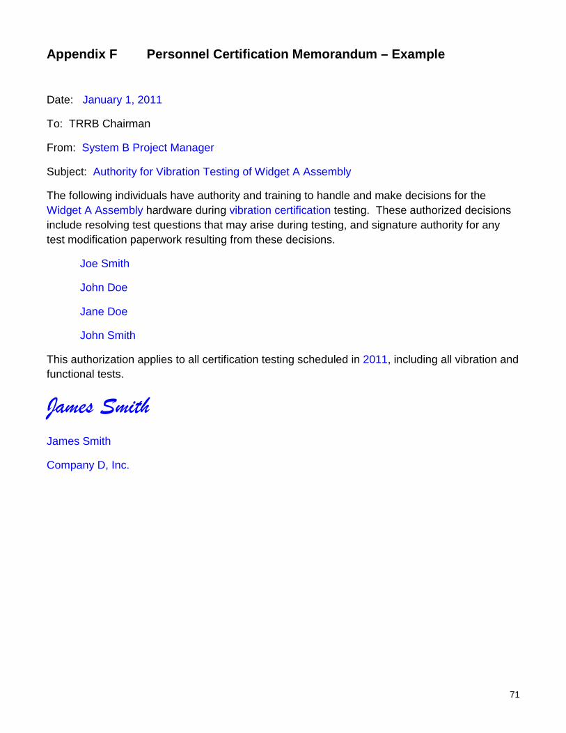
Appendix F Personnel Certification Memorandum – Example
Date: January 1, 2011
To: TRRB Chairman
From: System B Project Manager
Subject: Authority for Vibration Testing of Widget A Assembly
The following individuals have authority and training to handle and make decisions for the Widget A Assembly hardware during vibration certification testing. These authorized decisions include resolving test questions that may arise during testing, and signature authority for any test modification paperwork resulting from these decisions.
Joe Smith
John Doe
Jane Doe
John Smith
This authorization applies to all certification testing scheduled in 2011, including all vibration and functional tests.
James Smith James Smith
Company D, Inc.