VHF TRANSCEIVER iF110 - Icom · IMPORTANT READ ALL INSTRUCTIONS carefully and com- pletely before...
24
INSTRUCTION MANUAL iF210 UHF TRANSCEIVER iF110 VHF TRANSCEIVER
Transcript of VHF TRANSCEIVER iF110 - Icom · IMPORTANT READ ALL INSTRUCTIONS carefully and com- pletely before...

INSTRUCTION MANUAL
iF210UHF TRANSCEIVER
iF110VHF TRANSCEIVER
�
IMPORTANT
READ ALL INSTRUCTIONS carefully and com-pletely before us�ng the transce�ver.
SAVE THIS INSTRUCTION MANUAL — Th�s �n-struct�on manual conta�ns �mportant operat�ng �nstruct�ons for the IC-F110 VHF TRANSCEIVER and IC-F210 UHF TRANS-CEIVER.
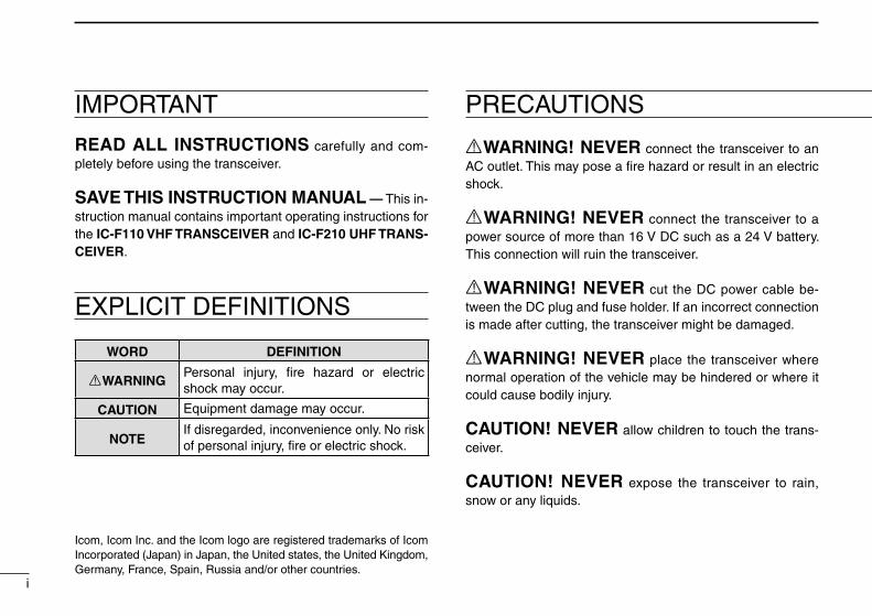
EXPLICIT DEFINITIONS
WORD DEFINITION
RWARNINGPersonal �njury, fire hazard or electr�c shock may occur.
CAUTION Equ�pment damage may occur.
NOTEIf d�sregarded, �nconven�ence only. No r�sk of personal �njury, fire or electr�c shock.
RWARNING! NEVER connect the transce�ver to an AC outlet. Th�s may pose a fire hazard or result �n an electr�c shock.
RWARNING! NEVER connect the transce�ver to a power source of more than 16 V DC such as a 24 V battery. Th�s connect�on w�ll ru�n the transce�ver.
RWARNING! NEVER cut the DC power cable be-tween the DC plug and fuse holder. If an �ncorrect connect�on �s made after cutt�ng, the transce�ver m�ght be damaged.
RWARNING! NEVER place the transce�ver where normal operat�on of the veh�cle may be h�ndered or where �t could cause bod�ly �njury.
CAUTION! NEVER allow ch�ldren to touch the trans-ce�ver.
CAUTION! NEVER expose the transce�ver to ra�n, snow or any l�qu�ds.
PRECAUTIONS
Icom, Icom Inc. and the Icom logo are reg�stered trademarks of Icom Incorporated (Japan) �n Japan, the Un�ted states, the Un�ted K�ngdom, Germany, France, Spa�n, Russ�a and/or other countr�es.

PRECAUTIONS TABLE OF CONTENTS
USE the suppl�ed m�crophone only. Other m�crophones have d�fferent p�n ass�gnments and may damage the transce�ver.
DO NOT use or place the transce�ver �n areas w�th tem-peratures below –25°C or above +55°C, or �n areas subject to d�rect sunl�ght, such as the dashboard.
DO NOT operate the transce�ver w�thout runn�ng the ve-h�cle’s eng�ne. The veh�cle’s battery w�ll qu�ckly run out �f the transce�ver transm�ts wh�le the veh�cle’s eng�ne OFF.
DO NOT place the transce�ver �n excess�vely dusty env�-ronments.
DO NOT place the transce�ver aga�nst walls. Th�s w�ll ob-struct heat d�ss�pat�on.
DO NOT use of chem�cal agents such as benz�ne or alco-hol when clean�ng, as they damage the transce�ver surfaces.
BE CAREFUL! The transce�ver w�ll become hot when operat�ng cont�nuously for long per�ods.
��
IMPORTANT .......................................................................... �EXPLICIT DEFINITIONS ....................................................... �PRECAUTIONS ..................................................................... �TABLE OF CONTENTS ........................................................ ��
1 PANEL DESCRIPTION ................................................1–6 ■ Front panel ...................................................................1 ■ Funct�on d�splay ...........................................................2 ■ Programmable funct�on keys ........................................3
2 OPERATION ..............................................................7–10 ■ Turn�ng power ON ........................................................7 ■ Channel select�on .........................................................7 ■ Rece�v�ng and transm�tt�ng ...........................................8
3 CONNECTION AND MAINTENANCE ....................11–15 ■ Rear panel and connect�on ........................................11 ■Suppl�ed Accessor�es .................................................12 ■Mount�ng the transce�ver ............................................13 ■ Opt�onal UT-108 �nstallat�on .......................................13 ■ Opt�onal UT-109 or UT-110 �nstallat�on .......................14 ■ Opt�onal OPC-617 �nstallat�on ....................................... 14 ■ Antenna ......................................................................15 ■ Fuse replacement ......................................................15 ■ Clean�ng .....................................................................15
4 OPTIONS .......................................................................16
5 CE ............................................................................17–18

y t r
q w e
■ Front panel
q AF VOLUME CONTROL KNOB Rotate the knob to adjust the aud�o output level. • M�n�mum aud�o level �s pre-programmed.
w FUNCTION DISPLAY D�splays a var�ety of �nformat�on, such as an operat�ng
channel number/name, 5-tone code, DTMF numbers and aud�ble cond�t�on, etc.
NOTE: The above funct�ons depend on pre-programm�ng.
e UP/DOWN [ ]/[ ] KEYS ➥ Push to select the operat�ng channel. ➥ Can be programmed for one of several funct�ons by
your dealer. (Same as [P0] to [P3] keys)
r POWER SWITCH [POWER] Push to turn the power ON and OFF. • The follow�ng funct�ons are ava�lable at power ON as opt�ons: - Automat�c scan start - Password prompt - Set mode
1
1 PANEL DESCRIPTION

2
1PANEL DESCRIPTION
t DEALER-PROGRAMMABLE KEYS [P0] to [P3] Des�red funct�ons can be programmed �ndependently by
your dealer.
y MICROPHONE CONNECTOR Connect the suppl�ed or opt�onal m�crophone. NEVER connect non-spec�fied m�crophones. The p�n
ass�gnments may be d�fferent and the transce�ver may be damaged.
D MICROPHONEThe suppl�ed or opt�onal m�crophone has a PTT sw�tch and a hanger hook.• The follow�ng funct�ons are ava�lable when the m�crophone �s on or
off hook: - Automat�c scan start when on hook. - Automat�c pr�or�ty channel select�on when off hook. - Sets to ‘Inaud�ble’ cond�t�on (mute cond�t�on) when on hook. - Sets to ‘Aud�ble’ cond�t�on (unmute cond�t�on) when off hook.
■ Function display
q w e r t y u
i
qTRANSMIT INDICATOR Appears wh�le transm�tt�ng.
wBUSY INDICATOR Appears wh�le the channel �s busy.
eSIGNAL STRENGTH METER Ind�cates relat�ve rece�ve s�gnal strength level.
rLOW POWER INDICATOR Appears when low output power �s selected.
tAUDIBLE INDICATOR Appears when the channel �s �n the ‘Aud�ble’ cond�t�on (un-
mute cond�t�on).
ySCRAMBLER INDICATOR Appears when the scrambler funct�on �s act�vated. (Op-
t�onal UT-109 (#02)/UT-110 (#02) SCRAMBLER UNIT �s requ�red.)

3
1 PANEL DESCRIPTION
■ Programmable function keys
The follow�ng funct�ons can be ass�gned to [P0], [P1], [P2], [P3], [ ] and [ ] programmable funct�on keys.Consult your Icom dealer for deta�ls concern�ng your trans-ce�ver’s programm�ng.In the follow�ng explanat�ons, programmable funct�on names are bracketed. The spec�fic sw�tch used to act�vate the func-t�on depends on programm�ng.
• CH UP AND DOWN KEYSCH UP
CH DN
➥ Select an operat�ng channel.➥ Select a transm�t code channel after push�ng
the [TX CH] key.➥ Select a DTMF channel after push�ng the
[DTMF] key.➥ Select a scan group after push�ng and hold�ng
the [SCAN] key.
• BANK KEYBANK Select and determ�ne a bank number.
u2/5TONE INDICATOR Appears when the spec�fied 2/5-tone call �s rece�ved.
i ALPHANUMERIC DISPLAY D�splays the CH number, 5-tone �nd�cat�on, DTMF num-
bers, Aud�ble �nd�cat�on, etc.
NOTE: When the alphanumer�c d�splay bl�nks and trans-m�tt�ng becomes �mposs�ble, check that the DC battery voltage has not dropped below 8 V or that the antenna �s not tuned properly or the antenna connect�on �s faulty.

4
1PANEL DESCRIPTION
• SCAN START/STOP KEYPush th�s key to start scann�ng; and push aga�n to stop.
NOTE: Place the m�crophone on hook to start scann�ng.Take the m�crophone off hook to stop scann�ng.
• SCAN TAG KEYTAG Adds or deletes the selected channel to the scan
group.
• PRIORITY CHANNEL KEYSPush these keys to select pr�or�ty A or pr�or�ty B channel, respect�vely.
• OPERATING CHANNEL KEYSMR-1
MR-2
MR-3
MR-4
Select an operat�ng channel d�rectly.
• MONITOR KEYMONI Act�vates one of (or two of) the follow�ng funct�ons
on each channel �ndependently:• Push and hold the key to unmute the channel (aud�o �s
em�tted; ‘Aud�ble’ cond�t�on).• Push the key to toggle between the mute and unmute
cond�t�ons (toggles between ‘Aud�ble’ and ‘Inaud�ble’).• Push the key to mute the channel (sets to ‘Inaud�ble’
only).• Push the key to unmute the channel (sets to ‘Aud�ble’
only).• Push the key after commun�cat�on �s fin�shed to send a
‘reset code’.
NOTE: The unmute cond�t�on (‘Aud�ble’ cond�-t�on) may automat�cally return to the mute con-d�t�on (‘Inaud�ble’ cond�t�on) after a spec�f�ed per�od depend�ng on the pre-sett�ng.
• LOCK KEYLOCK Push th�s key for 1 sec. to lock all programmable
keys except the follow�ng:• [CALL] (�ncl. [CAL A] and [CAL B]), [MONI] and
[EMER] keys.

5
1 PANEL DESCRIPTION
• OUTPUT POWER SELECTION KEYSSelect the transm�t output power temporar�ly, or permanently, depend�ng on the pre-sett�ng.• Contact your dealer for the output power level for each
select�on.
• TALK AROUND KEYTA Turns the talk around funct�on ON and OFF.
• The talk around funct�on equal�zes the transm�t fre-quency to the rece�ve frequency for mob�le-to-mob�le commun�cat�on.
• WIDE/NARROW KEYPush th�s key to toggle the bandw�dth between w�de or narrow.
• DTMF AUTODIAL KEYDTMF Push th�s key to d�splay the text of the DTMF chan-
nel number and set the des�red channel number v�a the [ ]/[ ] key. Then, push th�s key aga�n to transm�t a spec�fied DTMF code.
• CALL KEYTransm�t a 2-tone, 5-tone code.• Call transm�ss�on �s necessary before you call another
stat�on depend�ng on your s�gnal�ng system.• The [CAL A] and/or [CAL B] keys may be ava�lable
when your system employs select�ve ‘Ind�v�dual/Group’ calls. Contact your dealer about wh�ch call �s ass�gned to each key.
• EMERGENCY KEYEMER Push and hold the key to transm�t an emergency call.
• If you want to cancel the emergency call, push and hold (or push) the key aga�n before transm�tt�ng the call.
• Depend�ng on the pre-sett�ng, the emergency call �s transm�tted one t�me only, or repeatedly, unt�l rece�v�ng a control code.
• HOOK SCANWhen the Hook Scan funct�on �s turned ON, push th�s key to stop scann�ng temporar�ly. Push th�s key aga�n to re-start scann�ng.
• TX CODE KEY
TX CH Select a transm�t 5-tone code (stat�on code) chan-nel.
6
1PANEL DESCRIPTION
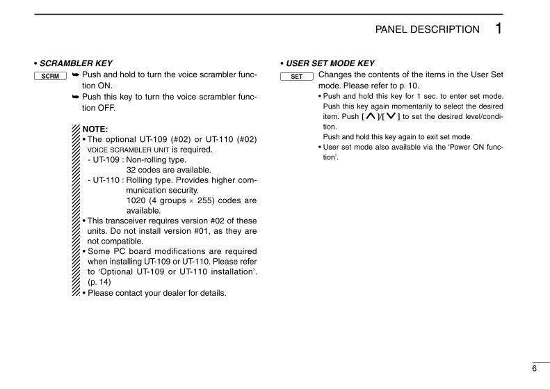
• SCRAMBLER KEYSCRM ➥ Push and hold to turn the vo�ce scrambler func-
t�on ON.➥ Push th�s key to turn the vo�ce scrambler func-
t�on OFF.
NOTE:• The opt�onal UT-109 (#02) or UT-110 (#02)
voice scrambler unit �s requ�red. - UT-109 : Non-roll�ng type. 32 codes are ava�lable. - UT-110 : Roll�ng type. Prov�des h�gher com-
mun�cat�on secur�ty. 1020 (4 groups × 255) codes are
ava�lable.• Th�s transce�ver requ�res vers�on #02 of these
un�ts. Do not �nstall vers�on #01, as they are not compat�ble.
• Some PC board mod�f�cat�ons are requ�red when �nstall�ng UT-109 or UT-110. Please refer to ‘Opt�onal UT-109 or UT-110 �nstallat�on’. (p. 14)
• Please contact your dealer for deta�ls.
• USER SET MODE KEY
SET Changes the contents of the �tems �n the User Set mode. Please refer to p. 10.• Push and hold th�s key for 1 sec. to enter set mode.
Push th�s key aga�n momentar�ly to select the des�red �tem. Push [ ]/[ ] to set the des�red level/cond�-t�on.
Push and hold th�s key aga�n to ex�t set mode.• User set mode also ava�lable v�a the ‘Power ON func-
t�on’.

7
2 OPERATION
■ Turning power ON
q Push [ ] to turn the power ON.w If the transce�ver �s programmed for a start up passcode,
�nput the d�g�t codes as d�rected by your dealer. • The keys �n the table below can be used for password �nput: • The transce�ver detects numbers �n the same block as �dent�cal.
Therefore “01234” and “56789” are same.
e When the “PASSWORD” �nd�cat�on does not clear after �n-putt�ng 4 d�g�ts, the �nput code number �s �ncorrect. In th�s case, turn the power off and start over.
■ Channel selection
Several types of channel select�on are ava�lable. The meth-ods may d�ffer accord�ng to your system setup.
NON-BANK TYPE:Push [ ]/[ ] to select the des�red operat�ng channel �n sequence; or, push one of the [CH 1] to [CH 4] keys to select a channel d�rectly.
BANK-TYPE: Push [BANK] to select the des�red bank number or name.
AUTOMATIC SCAN TYPE:Channel sett�ng �s not necessary for th�s type. When turn�ng the power ON, the transce�ver automat�cally starts scann�ng. Scann�ng stops when rece�v�ng a call or when tak�ng the m�-crophone off hook.
KEY
NUMBER 0 1 2 3 4
5 6 7 8 9

8
2OPERATION
■ Receiving and transmitting
RECEIVING:q Push [ ] to turn the power ON.w Push [ ] or [ ] to select a channel.e When rece�v�ng a call, adjust the aud�o output level to a
comfortable l�sten�ng level.
TRANSMITTING:q Take the m�crophone off hook. • 2-tone, 5-tone mute may be released. (The ‘aud�ble’ cond�t�on �s
selected and “ ” appears.) • A pr�or�ty channel may be selected automat�cally.w Wa�t for the channel to become clear. • The channel �s busy when “ ” appears.e Push the [CALL] key when �n�t�at�ng a call from your s�de. • Coded aud�o may be heard from the transce�ver, then “ ” ap-
pears. • Th�s operat�on may not be necessary depend�ng on your s�gnal-
�ng system. Contact your dealer.r Wh�le push�ng and hold�ng [PTT], speak �nto the m�cro-
phone at your normal vo�ce level.t Release [PTT] to rece�ve.
IMPORTANT!: To max�m�ze the readab�l�ty of your s�gnal;➥ Pause br�efly after push�ng [PTT].➥ Hold the m�crophone 5 to 10 cm (2 to 4 �nches) from
your mouth, then speak �nto the m�crophone at a nor-mal vo�ce level.
D Transmitting notes• Transmit inhibit functionThe transce�ver has several �nh�b�t funct�ons wh�ch restr�ct transm�ss�on under the follow�ng cond�t�ons:- The channel �s �n mute cond�t�on (‘Inaud�ble’ cond�t�on; “ ” does not
appear).- Channel �s busy.- A matched/un-matched CTCSS code �s rece�ved.- The selected channel �s a ‘rece�ve only’ channel.
• Time-out timerAfter cont�nuous transm�ss�on for a pre-programmed per�od, the t�me-out t�mer �s act�vated caus�ng the transce�ver to stop transm�tt�ng and automat�cally select rece�ve.
• Penalty timerOnce the t�me-out t�mer �s act�vated, transm�ss�on �s further �nh�b�ted for a per�od determ�ned by the penalty t�mer.

9
2 OPERATION
D TX code channel selectionIf the transce�ver has a [TX CH] key, the d�splay can be tog-gled between the operat�ng channel number (or name) and TX code channel number (or name). When the TX code chan-nel number (or name) �s d�splayed, the [ ]/[ ] keys select the TX code channel.
To select a TX channel:q Push [TX CH]—a TX code channel appears.w Push [ ]/[ ] to select the des�red TX code channel.e After select�ng, push [TX CH] to set. • Returns to the stand-by mode.
r Push [CALL] to transm�t the selected TX code.
D TX code number selectionIf the transce�ver has a [TX CH] key, TX code contents can be changed w�th�n the allowable d�g�ts.
To select a TX code:q Push [TX CH]—a TX code number appears and the first
d�g�t bl�nks.w Push [ ]/[ ] to select the des�red number of the bl�nk-
�ng d�g�t.e Push [TX CH] to enter the selected number and the next
d�g�t w�ll start bl�nk�ng automat�cally.r Repeat step w and e to �nput all allowed d�g�ts.t Push [CALL] to transm�t the selected TX code.
D DTMF transmissionIf the transce�ver has a [DTMF] key, the automat�c DTMF transm�ss�on funct�on �s ava�lable. Up to 7 DTMF channels may be ava�lable.
To transmit a DTMF code:q Push [DTMF]—a DTMF code channel appears.w Push [ ]/[ ] to select the des�red DTMF channel.e Push and hold [DTMF] to transm�t the DTMF code on the
selected DTMF channel.
D Scrambler functionThe UT-109 (#02) or UT-110 (#02) opt�onal vo�ce scrambler un�t prov�des h�gh performance pr�vate commun�cat�on be-tween stat�ons w�th the same scrambler codes.
To turn the scrambler function ON and OFF:q Push and hold [SCRM] to turn the scrambler funct�on ON.w Push [SCRM] to turn the funct�on OFF.

D User set modeUser set mode �s accessed at power ON and allows you to set seldom-changed sett�ngs. In th�s case you can “custom-�ze” transce�ver operat�on to su�t your preferences and operat-�ng style.
Entering the user set mode:q Wh�le push�ng and hold�ng [ ] and [ ], push [POWER]
to enter user set mode ON, allow�ng you to set seldom-changed sett�ngs.
w Push and hold [P0] to select the appropr�ate �tem. Then, push [ ] or [ ] to set the des�red level/mode.
- Ava�lable set mode funct�ons; • Backl�ght : OFF, D�m, Auto or ON • Beep : OFF or ON • SQL Level : 0 to 255 • AF M�n level : 0 to 255e Push [POWER] (or push and hold [P0]) aga�n to ex�t set
mode.
User set mode �s also ava�lable v�a a programmable key. Please refer to p. 6 [SET] sect�on.[SET] �s allowed for the qu�ck �tem select�on. Set “Enable” for the often used �tems w�th the CS-F100 cloning software.
10
2OPERATION

Optional speaker (SP-22)
Optional cable (OPC-617)
Antenna
+red:
black:
12VBattery
e
r
t
w
q
SolderCrimp
NOTE: Use the terminals as shown below for the cable connections.
R WARNING! NEVER re-move the fuse-holder from the DC power cable.
R WARNING! NEVER con-nect to a 24 V battery.
■ Rear panel and connection
11
3 CONNECTION AND MAINTENANCE

qANTENNA CONNECTOR Connects to an antenna. Contact your dealer about an-
tenna select�on and placement.
w MICROPHONE HANGER Connect the suppl�ed m�crophone hanger to the veh�cle’s
ground for m�crophone on/off hook funct�ons. (See p. 2)
eDC POWER RECEPTACLE Connects to a 12 V DC battery. Pay attent�on to polar�t�es. R WARNING! NEVER connect to a 24 V battery. Th�s
could damage the transce�ver.
rOPTIONAL CABLE (OPC-617) Connect an external modem un�t, d�mmer control, etc.
tEXTERNAL SPEAKER JACK Connect a 4–8 ø external speaker, �f des�red.
■Supplied Accessories
q w e r
yu
i
o
!0 !1 !2
t
q M�crophone ...................... 1w M�crophone hanger and
screw set ..................... 1 sete M�crophone hanger cable . 1r DC power cable (OPC-1194A) ............................................1t Funct�on name st�ckers*
(KEY STICKER) ....................1
y Mount�ng bracket ............... 1u Bracket bolts ..................... 4i Mount�ng screws (M5×12) . 4o Self-tapp�ng screws (M5×20)
........................................... 4!0 Flat washers ...................... 4!1 Spr�ng washers ................. 4!2 Nuts ................................... 4
*Function name stickersThere are no names on the programmable funct�on keys s�nce the funct�ons can be freely ass�gned to these keys.Attach the suppl�ed funct�on name st�ckers above the appropr�ate keys for easy recogn�t�on of that key’s ass�gned funct�on.
12
3CONNECTION AND MAINTENANCE

■Mounting the transceiver
The un�versal mount�ng bracket suppl�ed w�th your transce�ver allows overhead mount�ng.• Mount the transce�ver securely w�th the 4 suppl�ed screws
to a th�ck surface wh�ch can support more than 1.5 kg.
Felt*
When usingself-tapping screws
Spring washer
Flat washerNut
*Felts reduce the vibration effects.
Felt*
■ Optional UT-108 installation
Install the opt�onal UT-108 un�t as follows:
q Turn the power OFF, then d�sconnect the DC power cable.w Unscrew the 4 cover screws, then remove the bottom
cover.e Install the un�t as shown �n the d�agram below.r Replace the bottom cover and screws, then re-connect
the DC power cable.
UT-108
Front panel
13
3 CONNECTION AND MAINTENANCE

■ Optional UT-109 or UT-110 installation
q Turn the power OFF, then d�sconnect the DC power cable.w Unscrew the 4 cover screws, then remove the bottom
cover.e Cut the pattern on the PCB at the TX m�c c�rcu�t (MIC) and
RX AF c�rcu�t (DISC) as shown below.r Install the scrambler un�t as descr�bed �n the �nstallat�on of
opt�onal UT-108 as on the page at left.t Replace the bottom cover and screws.
Front panelMICDISC
NOTE: Be sure to re-solder the above d�sconnected po�nts when you remove the scrambler un�ts. Otherw�se no TX modulat�on or AF out-put �s ava�lable.
■ Optional OPC-617 installation
Install the OPC-617 as shown below.
OPC-617
Cut off the bushing as in the illustration, when you install the optional OPC-617.
q D�mmer cont. IN or IGSW cont. INw AF OUTe Det. AF OUT r Mod. INt PTT control IN or
y Horn dr�ve cont. OUTu AF GNDi Det. AF GNDo Mod. GND
OPTIONAL CABLE PIN ASSIGNMENT
t r e w q
o i u yFTSW control IN
14
3CONNECTION AND MAINTENANCE

■ Antenna
A key element �n the performance of any commun�cat�on sys-tem �s an antenna. Contact your dealer about antennas and the best places to mount them.
■ Fuse replacement
A fuse �s �nstalled �n the suppl�ed DC power cable. If a fuse blows or the transce�ver stops funct�on�ng, track down the source of the problem �f poss�ble, and replace the damaged fuse w�th a new rated one.❑ Fuse rat�ng: 10 A
■ Cleaning
If the transce�ver becomes dusty or d�rty, w�pe �t clean w�th a soft, dry cloth.
AVOID the use of solvents such as benzene or al-cohol, as they may damage the transce�ver sur-faces.
15
3 CONNECTION AND MAINTENANCE

• SP-22 external speaker
Compact and easy-to-�nstall. Input �mpedance : 4 ø Max. �nput power : 5 W
• HM-152/HM-152T/HM-148G/HM-148T hand microphones
HM-152 : Hand m�crophone HM-152T : DTMF m�crophone HM-148G : Self ground heavy duty m�crophone HM-148T : Self ground heavy duty DTMF m�crophone The 10-keypad of th�s m�crophone can be used
for the DTMF code transm�ss�on only.
• SM-25 desktop microphone
• UT-108 dtmf decoder unit
Prov�des pager and code squelch capab�l�t�es.
• UT-109/UT-110 (#02) scrambler units
UT-109 : Non-roll�ng type (max. 32 codes) UT-110 : Roll�ng type (max. 1020 codes)
• OPC-617 acc cable
Allows you to connect to an external term�nal.
Approved Icom opt�onal equ�pment �s des�gned for opt�mal performance when used w�th an Icom transce�ver.Icom �s not respons�ble for the destruct�on or damage to an Icom transce�ver �n the event the Icom transce�ver �s used w�th equ�pment that �s not manufactured or approved by Icom.
Some opt�ons may not be ava�lable �n some countr�es. Please ask your dealer for deta�ls.
16
4OPTIONS

17
5 CE
CE Vers�ons of the IC-F110/IC-F210 wh�ch d�s-play the “CE” symbol on the ser�al number label, comply w�th the essent�al requ�rements of the European Rad�o and Telecommun�cat�on Term�-nal D�rect�ve 1999/5/EC.
Th�s warn�ng symbol �nd�cates that th�s equ�pment operates �n non-harmon�sed frequency bands and/or may be subject to l�cens�ng cond�t�ons �n the country of use. Be sure to check that you have the correct vers�on of th�s rad�o or the correct program-m�ng of th�s rad�o, to comply w�th nat�onal l�cens-�ng requ�rement.
DECLARATIONOF CONFORMITY
We Icom Inc. Japan1-1-32, Kamiminami, Hirano-kuOsaka 547-0003, Japan
Kind of equipment:
Type-designation:
Signature
Authorized representative name
Place and date of issue
Declare on our sole responsibility that this equipment complies with theessential requirements of the Radio and Telecommunications Terminal Equipment Directive, 1999/5/EC, and that any applicable Essential TestSuite measurements have been performed.
Version (where applicable):
This compliance is based on conformity with the following harmonised standards, specifications or documents:
136–174 MHz 12.5 kHz/ 25 kHz136–174 MHz 12.5 kHz/ 20 kHz
EN 301 489-1 (August 2000)EN 301 489-5 (August 2000)EN 60 950 (August 1992 +A11) EN 300 086-2 (March 2001) EN 300 219-2 (March 2001)
0168Düsseldorf
VHF TRANSCEIVER
iC-f110
i)ii)iii)iv)v)
vii)viii)
18th Nov. 2002

DECLARATIONOF CONFORMITY
We Icom Inc. Japan1-1-32, Kamiminami, Hirano-kuOsaka 547-0003, Japan
Kind of equipment:
Type-designation:
Signature
Authorized representative name
Place and date of issue
Declare on our sole responsibility that this equipment complies with theessential requirements of the Radio and Telecommunications Terminal Equipment Directive, 1999/5/EC, and that any applicable Essential TestSuite measurements have been performed.
Version (where applicable):
This compliance is based on conformity with the following harmonised standards, specifications or documents:
440–490 MHz 12.5 kHz/ 25 kHz440–490 MHz 12.5 kHz/ 20 kHz400–430 MHz 12.5 kHz/ 25 kHz
EN 301 489-1 (August 2000)EN 301 489-5 (August 2000)EN 60950 (August 1992 +A11) EN 300 086-2 (March 2001) EN 300 219-2 (March 2001)
0168Düsseldorf
UHF TRANSCEIVER
iC-f210
i)ii)iii)iv)v)
vii)viii)
15th Jan. 2003
About e-marking: Deta�led �nstallat�on notes for Icom mob�le transce�vers to be fitted �nto veh�cles are ava�lable. Please contact your Icom dealer or d�str�butor.
18
5CE

MEMO

MEMO

1-1-32 Kam�m�nam�, H�rano-ku, Osaka 547-0003, Japan
A-6234H-1EU-ePr�nted �n Japan© 2002–2009 Icom Inc.
< Intended Country of Use > GER AUT GBR IRL NOR
FRA NED BEL LUX
ESP POR ITA GRE
SWE DEN FIN SUI