VF-nC3 Motor Control instruction manual (detail edition) · Motor Control instruction manual...
30
E6581800② VF-nC3 Motor Control instruction manual (detail edition) Confidential ㊙ This manual is the engineering fortune of Toshiba Schneider Inverter Corporation. All of the release, reproduction, diversion and alteration of contents are strictly prohibited. The firmware will be updated without any notice. This manual is deals with firmware “Ver110”.
Transcript of VF-nC3 Motor Control instruction manual (detail edition) · Motor Control instruction manual...

E6581800②
VF-nC3 Motor Control instruction manual
(detail edition)
Confidential ㊙ This manual is the engineering fortune of
Toshiba Schneider Inverter Corporation.
All of the release, reproduction, diversion
and alteration of contents are strictly
prohibited.
The firmware will be updated without any notice.
This manual is deals with firmware “Ver110”.

E6581800
1
目次
1 PARAMETERS FOR MOTOR CONTROL ......................................................................................................... 3
2 ADJUSTMENT OF SPEED LOOP GAIN AT PT=3,4 ....................................................................................... 5
2.1 PARAMETER SETTING...........................................................................................................................................5 2.1.1 About F459 ..................................................................................................................................................5 2.1.2 About F460 .................................................................................................................................................7 2.1.3 Adjustment of F459, F460, F461...............................................................................................................8
2.2 PARAMETER ADJUSTMENT..................................................................................................................................10
3 CURRENT DIFFERENTIAL GAIN FOR PT=0,1,2......................................................................................... 11
3.1 PARAMETER SETTING .........................................................................................................................................11 3.2 PARAMETER ADJUSTMENT..................................................................................................................................11
4 OVER VOLTAGE PREVENTION CONTROL ................................................................................................. 12
4.1 PARAMETER SETTING .........................................................................................................................................12 4.2 VALIDATION .......................................................................................................................................................12
4.2.1 The relation deceleration time and stop distance (compared to nC1)...................................................12 4.2.2 The relation the parameter F305,F307 and stop distance.................................................................... 13 .
5 F480(FLUX ENHANCEMENT AT LOW SPEED) ......................................................................................... 14
5.1 PARAMETER SETTING .........................................................................................................................................14 5.2 PARAMETER ADJUSTMENT..................................................................................................................................14
6 F485(STALL REDUCTION AT FIELD WEAKENING AREA) ...................................................................... 15
6.1 PARAMETER SETTING .........................................................................................................................................15 6.2 PARAMETER ADJUSTMENT..................................................................................................................................15 6.3 THE EXAMPLE OF ADJUSTMENT..........................................................................................................................15
7 F495(OVER MODULATION / MAXIMUM VOLTAGE ADJUSTMENT)....................................................... 16
7.1 PARAMETER SETTING .........................................................................................................................................16 7.2 PARAMETER ADJUSTMENT..................................................................................................................................16
8 POWER RIDE THROUGH................................................................................................................................ 17
8.1 PARAMETER SETTING .........................................................................................................................................17 7.2 PARAMETER ADJUSTMENT..................................................................................................................................17
9 SPEED SEARCH ............................................................................................................................................... 18
9.1 PARAMETER SETTING .........................................................................................................................................18 9.2 PARAMETER ADJUSTMENT.................................................................................................................................18 9.3 THE SEQUENCE OF SPEED SEARCH ....................................................................................................................19 9.4 SPEED SEARCH DETAILED SEQUENCE RELATED TO PARAMETERS ......................................................................20
10 CARRIER FREQUENCY ................................................................................................................................ 21
10.1 PARAMETER SETTING .......................................................................................................................................21 10.2 CARRIER FREQUENCY FOR 3 PHASE MODULATION...........................................................................................21 10.3 CARRIER FREQUENCY AT SYNCHRONIZED PWM ..............................................................................................23 10.4 CARRIER FREQUENCY REDUCTION ...................................................................................................................24
11 OVER TORQUE TRIP ..................................................................................................................................... 25
11.1 PARAMETER SETTING .......................................................................................................................................25 11.2 DETECTION LEVEL............................................................................................................................................25

E6581800
2
11.3 DETAILS OF DETECTION ...................................................................................................................................25 11.4 VALIDATION .....................................................................................................................................................26
12 DC INJECTION............................................................................................................................................... 27
12.1 PARAMETER SETTING .......................................................................................................................................27 12.2 PARAMETER ADJUSTMENT ..............................................................................................................................27
13 ACCELERATION/DECELERATION OPERATION AFTER TORQUE LIMIT........................................... 28
13.1 PARAMETER SETTING .......................................................................................................................................28 13.2 PARAMETER ADJUSTMENT .............................................................................................................................28

E6581800
3
1 PARAMETERS FOR MOTOR CONTROL
Here after is the parameter list for VF-nC3 motor control.
nC3 motor parameter list
pt control law
0 1 2 3 4 parameter function
V/f
constant
Variable
torque
Automatic
torque
boost
Vector
control
Energy
saving
Accessibl
e during
running ? For what ?
vl[Hz] Basic frequency 1 ★ ★ ★ ★ ★ Yes V/f ratio
(rotor flux)
vlv[V] Basic voltage 1 ★ ★ ★ ★ ★ Yes V/f ratio
(rotor flux)
f405[kW] Motor rated power - - ★1 ★1 ★1 No Motor power
f412[%] motor coefficient
1 ○2 ○2 ○3 ○3 ○3 No Leakage coefficient
f415[A] Motor rated
current ○ ○ ★1 ★1 ★1 No Motor rated current
f416[%] Motor no load
current ○1 ○1 ○1 ○1 ○1 No Magnetizing current
f417
[rpm] Motor rated speed ☆2 ☆2 ★2 ★2 ★2 No
-Rated speed
-Rotor time constant
vb[%] Torque boost 1 ☆3 ☆3 - - - Yes Stator resistance compensation
Basic
parameter
f402[%] Automatic torque
boost - - ☆ ☆ ☆ Yes Stator resistance compensation
f401[%] Slip gain - - - ☆4 - Yes Slip gain
f480[%] motor coefficient
7 - - ☆5 ☆5 ☆5 No Increasing flux at low speed
f485[%] motor coefficient
8 ○4 ○4 ○4 ○4 ○4 No Current limit at field weakening
f495[%] motor coefficient
9 ○5 ○5 ○5 ○5 ○5 No Over -modulation rate
Adjust
parameter
f491 or
fb57[%]
motor coefficient
10 ○ ○ ○ ○ ○ No Ramp rate for speed search
f459 Load inertia - - - ☆6 ☆6 Yes Load inertia
f460[Hz] Motor special
constant 3 - - - ☆6 ☆6 Yes Speed loop gain
f461 Motor special
constant 4 - - - ☆6 ☆6 Yes Speed loop dumping coefficient
f462 Motor special
constant 5 - - - ○ ○ Yes Speed loop filter
f467 Motor special
constant 6 ○ ○ ○ - - Yes Current differential gain
fb52[Hz] OP stall gain ○ ○ ○ ○ ○ No OP stall gain
Speed loop
adjust
parameter
fb54[Hz]
Current
differential time
constant (inverse)
○ ○ ○ - - No Current differential time
constant (inverse) (Hz)

E6581800
4
f458[Hz] Current loop gain ○ ○ ○ ○ ○ No Current loop gain
Current
loop gain fb49
Current loop
dumping
coefficient
○ ○ ○ ○ ○ No Current loop dumping coefficient
*1 depends on the setting of “Set up menu”. Please refer to the instruction manual 11.5.
*2 depends on product range. Please refer to the instruction manual 11.4.
★ :the parameter to be set mandatory
☆ :the parameter to be set automatically by auto-tuning
○ :the parameter to be set if necessary
- :the parameter not to be used
★1:The parameters needed for the motor current of auto-tuning.
* it is necessary to set for special motor and small motor. It is also recommended to set for normal motor. ★2:The parameters is used for “rated slip” and “rotor time constant”.
If V/f ratio is changed from nominal state, rated speed is needed to change as below. Nr_new=Fn_new*60/P-Un/Fn*(Fn*60/P-Nr)*Fn_new/Un_new
☆3:The parameter is used for the output torque performance at low speed.
☆4:The parameter is to adjust slip compensation.
It is the rate for compensation to rated slip. ☆5:The parameter is flux rate at low speed. It is for enhance output torque at low speed (first it is necessary to do auto-tuning)
☆6:The speed loop gain is automatically adjusted by F459(load inertia) in case F460=0(default setting).
○1:The parameter is used for the calculation of “rotor time constant”. Normally not need to set.
It is better to set in case the value is known (by motor test report). ○2:The parameter is used for the calculation of “stator time constant”. Normally not need to set.
It effects dynamic performance of V/f control ramp stop . ○3:The parameter is used for the calculation of output voltage and “stator time constant”.
○4:It is necessary to set it for the improvement of speed stall at field weakening area.
○5:In case this parameter is small, current vibration is reduced at field weakening area, however, motor current is increased
which cause to motor maximum torque decrease.
E6581800
5
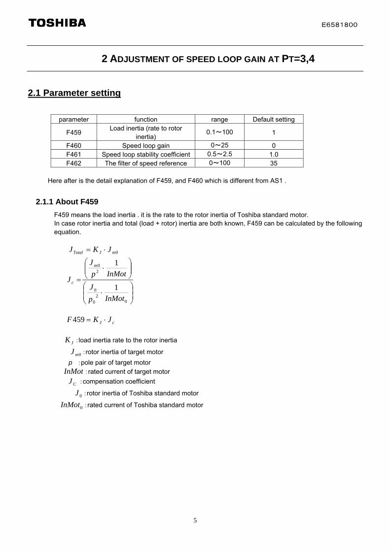
2 ADJUSTMENT OF SPEED LOOP GAIN AT PT=3,4
2.1 Parameter setting
parameter function range Default setting
F459 Load inertia (rate to rotor
inertia) 0.1~100 1
F460 Speed loop gain 0~25 0 F461 Speed loop stability coefficient 0.5~2.5 1.0 F462 The filter of speed reference 0~100 35
Here after is the detail explanation of F459, and F460 which is different from AS1 .
2.1.1 About F459
F459 means the load inertia . it is the rate to the rotor inertia of Toshiba standard motor. In case rotor inertia and total (load + rotor) inertia are both known, F459 can be calculated by the following equation.
0 mJTotal JKJ
02
0
0
20
1
1
InMotp
J
InMotp
J
J
m
c
cJ JKF 459
:load inertia rate to the rotor inertia JK
0mJ :rotor inertia of target motor
p :pole pair of target motor InMot :rated current of target motor
CJ :compensation coefficient
0J :rotor inertia of Toshiba standard motor
0 InMot :rated current of Toshiba standard motor

E6581800
6
The table below shows the inertia of Toshiba standard 4 pole motors which is used as the base inertia of F459. The data of 2 pole and 6 pole motors are reference data.
note) 0.2 to 0.75kW are steel framed motor, 1.5 to 3.7kW are aluminium die-cast framed motor.
■full closing type
power 2 pole 4 pole 6 pole (kW) Frame
size inertia Frame
size inertia Frame
size inertia
0.2 63M 0.00037 63M 0.00079 71M 0.0011 0.4 71M 0.00057 71M 0.0012 80M 0.0031
0.75 80M 0.0011 80M 0.0027 90L 0.0043 1.5 90L 0.0015 90L 0.004 100L 0.0067 2.2 100L 0.0021 100L 0.006 112M 0.0105 3.7 112M 0.0038 112M 0.0078 132S 0.0265
White cell: steel framed motor
Orange cell: aluminium die-cast framed motor
Even if Toshiba motor, inertia is possibly different in case the frame is different. In such case, F459 setting is needed. The table below is F459 setting in case of no load (motor only).
The value of F459 setting in case of no load (motor only)
Motor 2Pole(kW)
0.2 0.4 0.75 1.5 2.2 3.7
0.2 2.15
0.4 2.41 2.06
0.75 1.81 1.55 1.63
1.5 1.95 2.05 1.55
2.2 1.95 1.48 1.46
Inverter
(kW)
3.7 1.87 1.85 2.03
Motor 4Pole(kW)
0.2 0.4 0.75 1.5 2.2 3.7
0.2 1.00
0.4 1.12 1.00
0.75 0.85 0.75 1.00
1.5 0.95 1.26 1.00
2.2 1.20 0.95 1.00
Inverter
(kW)
3.7 1.20 1.26 1.00
Motor 6Pole(kW)
0.2 0.4 0.75 1.5 2.2 3.7
0.2
0.4 1.05
0.75 0.79 0.64
1.5 0.99 0.81 0.64
2.2 0.77 0.61 0.70
Inverter
(kW)
3.7 0.77 0.89 1.41

E6581800
7
In case the rate of load inertia and motor inertia is known, F459 can be set with the table above. For example, Inverter is nC3-2037, motor is 2.2kW 2-pole Toshiba standard motor (aluminium frame) , Load inertia(with motor) is 3 times of motor inertia, The recommended value of F459 is Kj * Jc = 1.85*3 = 5.6
2.1.2 About F460
F460 means speed loop gain (Hz).
In case F460=0(default setting), the gain is automatically calculated (it is described below in detail).
In case F460 is not 0, gain is equal to F460.
The speed loop gain has a limitation which is “150/F459” . For example, in case F459=100, the upper limitation of
speed loop gain is 150/100=1.5Hz even if F460 is higher than 1.5Hz.
Automatic adjustment of speed loop gain (F460=0)
The speed loop gain is calculated by 2kinds of inputs.
One is speed ramp rate, and other is load inertia.
The gain from speed ramp rate is
F0_ramp = MAX(3Hz , 0.0255*FH / Min(ACC,DEC) )
The gain from load inertia is
F0_inertia = 30 * (InDefMotor / InMotor) / F459
(InDefMotor: rated current of same sized motor, InMotor: rated motor current)
Final result of the gain is smaller one of both, furthermore it is limited between 1Hz to 10Hz.
F0_out = MIN(10Hz, MAX(1Hz, MIN(F0_ramp, F0_inertia)))
For example,
Inverter: nC3-2022 , Motor: 4P 2.2kW , FH=80 ACC=DEC=0.5
A: total inertia (F459) is 5.0
F0_ramp = MAX(3Hz, 0.0255*80 / 0.5) = 4Hz
F0_inertia = 30 / 5 = 6Hz
F0_out = MIN(10Hz, MAX(1Hz, MIN(F0_ramp, F0_inertia))) = 4Hz
A: total inertia (F459) is 10.0
F0_ramp = MAX(3Hz, 0.0255*80 / 0.5) = 4Hz
F0_inertia = 30 / 10 = 3Hz
F0_out = MIN(10Hz, MAX(1Hz, MIN(F0_ramp, F0_inertia))) = 3Hz

E6581800
8
2.1.3 Adjustment of F459, F460, F461
The figures below show the motor speed at each value of the parameter. The figure 1 shows the motor speed trend at each F459 in case the total inertia is 6 times of motor inertia. In case F459 is smaller than 6.0, motor speed is overshoot. On the contrary, F459 is bigger than 6.0, motor speed is little bit delayed to be stabilized.
Fig. 1 F459 adjustment
Figure 2 shows the motor speed trend at each F460 in case ACC=0.4sec. In case F460 is 0, F460 is automatically calculated to 5.0, motor speed is well tracked to speed reference. In case F460 is small, motor speed is delayed to speed reference.
Fig. 2 F460 adjustment
E6581800
9
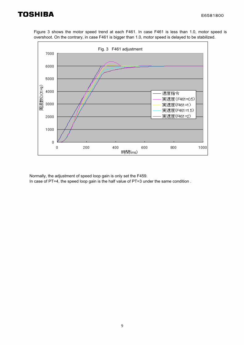
Figure 3 shows the motor speed trend at each F461. In case F461 is less than 1.0, motor speed is overshoot. On the contrary, in case F461 is bigger than 1.0, motor speed is delayed to be stabilized.
Fig. 3 F461 adjustment
Normally, the adjustment of speed loop gain is only set the F459. In case of PT=4, the speed loop gain is the half value of PT=3 under the same condition .
E6581800
10
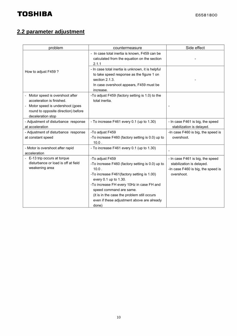
2.2 parameter adjustment
problem countermeasure Side effect
- In case total inertia is known, F459 can be
calculated from the equation on the section
2.1.1
-
How to adjust F459 ? - In case total inertia is unknown, it is helpful
to take speed response as the figure 1 on
section 2.1.3.
In case overshoot appears, F459 must be
increase.
-
- Motor speed is overshoot after
acceleration is finished.
- Motor speed is undershoot (goes
round to opposite direction) before
deceleration stop
-To adjust F459 (factory setting is 1.0) to the
total inertia.
-
- Adjustment of disturbance response
at acceleration
- To increase F461 every 0.1 (up to 1.30) - In case F461 is big, the speed
stabilization is delayed.
- Adjustment of disturbance response
at constant speed
-To adjust F459
-To increase F460 (factory setting is 0.0) up to
10.0 .
-In case F460 is big, the speed is
overshoot.
- Motor is overshoot after rapid
acceleration
- To increase F461 every 0.1 (up to 1.30) -
- E-13 trip occurs at torque disturbance or load is off at field weakening area
-To adjust F459
-To increase F460 (factory setting is 0.0) up to
10.0 .
-To increase F461(factory setting is 1.00)
every 0.1 up to 1.30.
-To increase FH every 10Hz in case FH and
speed command are same.
(it is in the case the problem still occurs
even if these adjustment above are already
done)
- In case F461 is big, the speed
stabilization is delayed.
-In case F460 is big, the speed is
overshoot.
E6581800
11
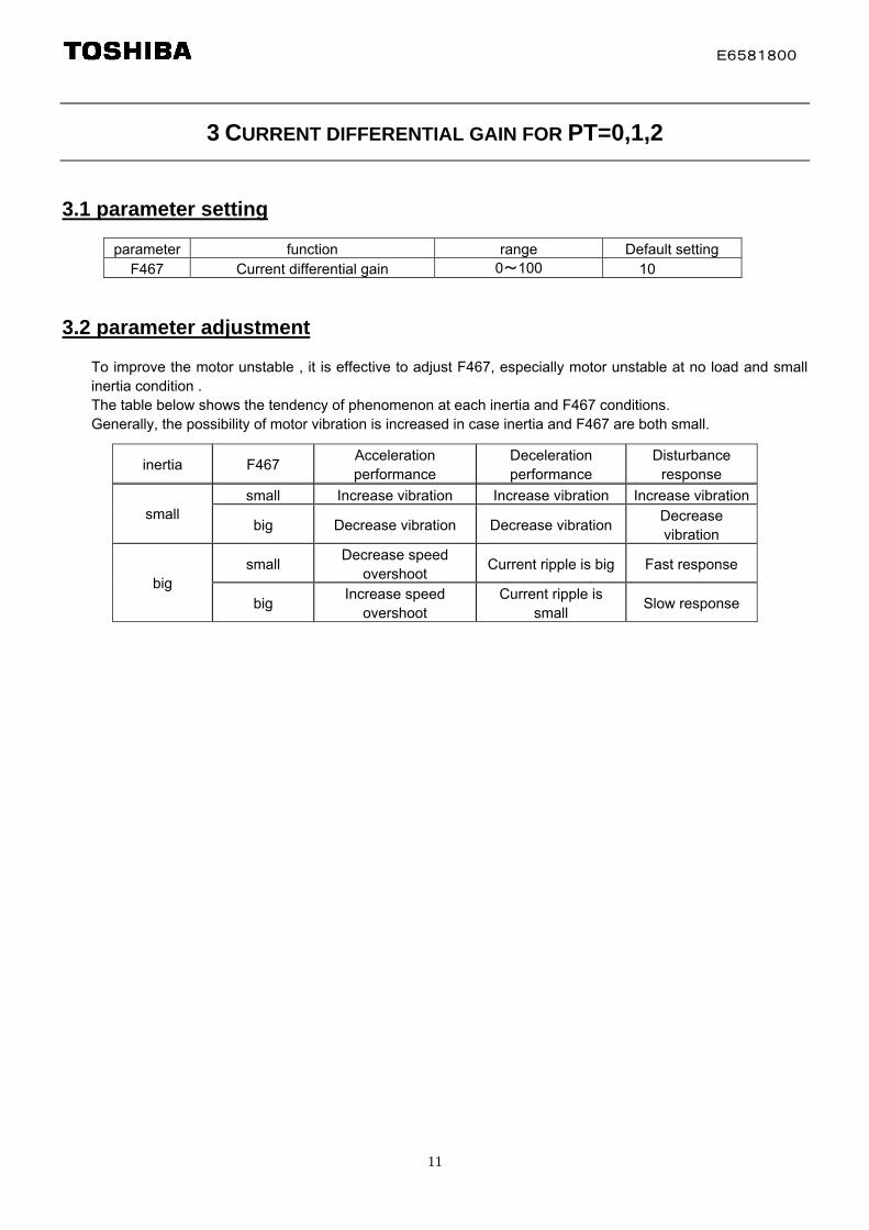
3 CURRENT DIFFERENTIAL GAIN FOR PT=0,1,2
3.1 parameter setting
parameter function range Default setting F467 Current differential gain 0~100 10
3.2 parameter adjustment
To improve the motor unstable , it is effective to adjust F467, especially motor unstable at no load and small inertia condition . The table below shows the tendency of phenomenon at each inertia and F467 conditions. Generally, the possibility of motor vibration is increased in case inertia and F467 are both small.
inertia F467 Acceleration performance
Deceleration performance
Disturbance response
small Increase vibration Increase vibration Increase vibrationsmall
big Decrease vibration Decrease vibration Decrease vibration
small Decrease speed
overshoot Current ripple is big Fast response
big big
Increase speed overshoot
Current ripple is small
Slow response

E6581800
12
4 OVER VOLTAGE PREVENTION CONTROL
4.1 parameter setting
parameter function range Default setting
F305 Over voltage prevention selection
0: enabled 1: disabled 2: enabled (rapid deceleration) 3: enabled (dynamic rapid deceleration)
2
4.2 validation
Here after is the result of the “stop distance(the distance from stop command is operated to finally stopped)” .
4.2.1 The relation deceleration time and stop distance (compared to nC1)
Deceleration characteristics
DEC [s] Pt=0 Pt=3 Pt=0 Pt=3 Pt=0 Pt=3 Pt=0 Pt=31.0 11915 130110.5 6544 7277 6150 6951 6313 7058 6176 69550.4 - - 5008 5622 - - - -0.3 - - OP2 OP2 - - - -0.1 5773 6219 OP2 OP2 4880 5091 3711 4102
DEC [s] Pt=0 Pt=3 Pt=0 Pt=3 Pt=0 Pt=31.0 12774 125340.5 7364 71860.1 5822 5725 5431 5396 5900 5681
DEC [s] Pt=0 Pt=3 Pt=0 Pt=3 Pt=0 Pt=3 Pt=0 Pt=31.0 20925 224650.8 - - 16831 18330 - - - -0.7 - - OP2 OP2 - - - -0.5 16840 18334 OP2 OP2 13587 14114 10731 118860.1 16303 16732 OP2 OP2 11453 11637 8525 9469
DEC [s] Pt=0 Pt=3 Pt=0 Pt=3 Pt=0 Pt=31.0 21580 216090.8 - - 17533 17483 - -0.7 - - 15635 15582 - -0.6 - - OP2 OP2 - -0.5 15187 15084 OP2 OP2 15027 147190.1 12522 12695 OP2 OP2 12265 12262
enabledynamic quick deceleration
F305=3F305=2 (Default)enable
quick decelerationFC=60Hz
FC=60HzF305=0 (Default) F305=1
F305=1
disable
F305=0
enable
F305=2
enable disableenable
quick deceleration
F305=2F305=1F305=0 (Default)enable
quick decelerationdisableenable
enabledynamic quick deceleration
enablequick deceleration
disableenable
F305=3F305=2 (Default)F305=1F305=0
same as F305=1
VFNC3-2022P
VFNC3-2022P
VFNC1-2022P <FC=60Hz>
same as F305=1 same as F305=1 same as F305=1
same as F305=1same as F305=1 same as F305=1
same as F305=1same as F305=1
same as F305=1
same as F305=1 same as F305=1
VFNC1-2022P
FC=80Hz
FC=80Hz

E6581800
13
4.2.2 The relation the parameter F305,F307 and stop distance
Pt=0 Fc=80Hz Dec=0.1s 減速特性Test25,26,27 vs 24NC3で、電源電圧補正あり、なしを比較した。F307=3(def)については、パラメータ(F305)により減速特F307=2(set)は、減速能力はF305を設定変更しても、同
性が変化する。一特性。
Test No F305 F30725 026 2(def) 327 3 def24 3 2
V/f制御 Fc=80Hz Dec=0.1s 減速特性
0.000
0.002
0.004
0.006
0.008
0.010
0.012
0.014
0.016
0 1000 2000 3000 4000 5000 6000 7000 8000 9000
Number of pulse counts
Test25 Test26 Test27 Test24 E720
NC3出荷設定F305=2(過励磁)
電圧補正なしF305=3(ダイナミック)F307=2
Here after is the test result comparing several combination of F305 and F307 on nC3. Test condition: PT=0, Fc=80Hz, DEC=0.1s In case F307=3, stop distance depends on F305. In case F307=2, stop distance is independent of F305.
E6581800
14
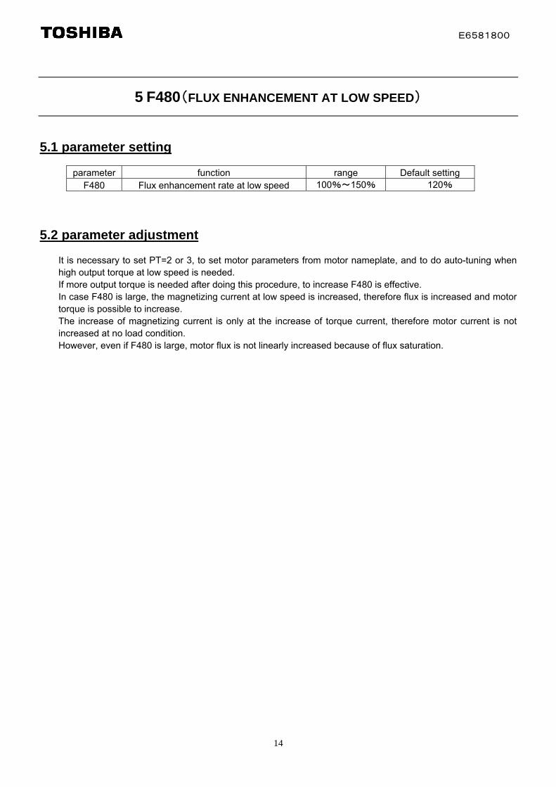
5 F480(FLUX ENHANCEMENT AT LOW SPEED)
5.1 parameter setting
parameter function range Default setting F480 Flux enhancement rate at low speed 100%~150% 120%
5.2 parameter adjustment
It is necessary to set PT=2 or 3, to set motor parameters from motor nameplate, and to do auto-tuning when high output torque at low speed is needed. If more output torque is needed after doing this procedure, to increase F480 is effective. In case F480 is large, the magnetizing current at low speed is increased, therefore flux is increased and motor torque is possible to increase. The increase of magnetizing current is only at the increase of torque current, therefore motor current is not increased at no load condition. However, even if F480 is large, motor flux is not linearly increased because of flux saturation.

E6581800
15
6 F485(STALL REDUCTION AT FIELD WEAKENING AREA)
6.1 parameter setting
parameter function range Default setting F485 Stall reduction at field weakening area 10-250 100
6.2 parameter adjustment
In case of the driving at field weakening area, motor flux is reduced therefore motor maximum torque is also reduced. In such condition, when instant torque is obtained motor is stalled even if motor current is less than current limitation. There are 2 conditions for field weakening area. One is over the base frequency, the other is DC bus voltage reduction. Especially single phase inverter, DC bus voltage is reduced in case of heavy load. In such case, reduction of F485 every 5 is effective.
problem countermeasure Side effect Motor is stalled in case of the driving with input voltage reduction, or at field weakening area
To reduce F485 every 5 Maximum torque at low speed is reduced
6.3 the example of adjustment
system: INV:nC3-2007 Motor:0.4kW-200V-60Hz input voltage:165V
Pt=3 F485=100 Pt=3 F485=50
Motor is stalled over 50Hz
No stall
Maximum torque at low speed is reduced
Motor speed [5Hz/div]
Motor torque [50%/div]
Motor current [20%/div]
E6581800
16
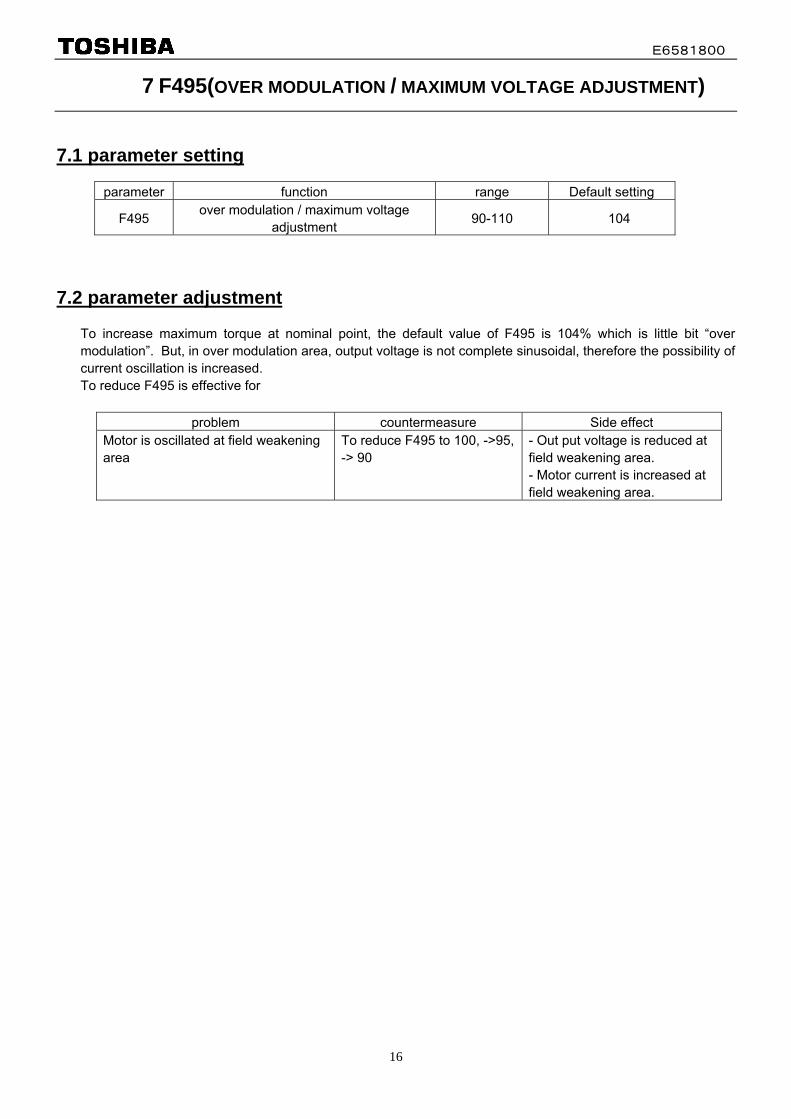
7 F495(OVER MODULATION / MAXIMUM VOLTAGE ADJUSTMENT)
7.1 parameter setting
parameter function range Default setting
F495 over modulation / maximum voltage
adjustment 90-110 104
7.2 parameter adjustment
To increase maximum torque at nominal point, the default value of F495 is 104% which is little bit “over modulation”. But, in over modulation area, output voltage is not complete sinusoidal, therefore the possibility of current oscillation is increased. To reduce F495 is effective for
problem countermeasure Side effect Motor is oscillated at field weakening area
To reduce F495 to 100, ->95, -> 90
- Out put voltage is reduced at field weakening area. - Motor current is increased at field weakening area.
E6581800
17
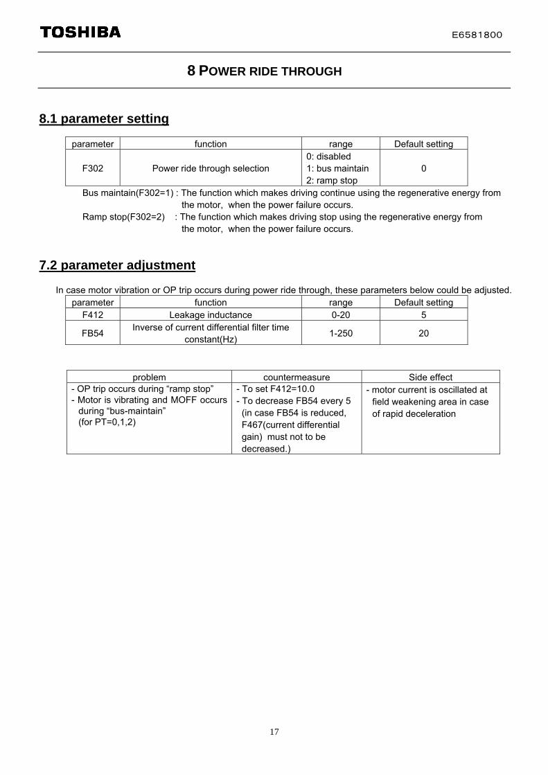
8 POWER RIDE THROUGH
8.1 parameter setting
parameter function range Default setting
F302 Power ride through selection 0: disabled 1: bus maintain 2: ramp stop
0
Bus maintain(F302=1) : The function which makes driving continue using the regenerative energy from the motor, when the power failure occurs. Ramp stop(F302=2) : The function which makes driving stop using the regenerative energy from the motor, when the power failure occurs.
7.2 parameter adjustment
In case motor vibration or OP trip occurs during power ride through, these parameters below could be adjusted. parameter function range Default setting
F412 Leakage inductance 0-20 5
FB54 Inverse of current differential filter time
constant(Hz) 1-250 20
problem countermeasure Side effect - OP trip occurs during “ramp stop” - Motor is vibrating and MOFF occurs
during “bus-maintain” (for PT=0,1,2)
- To set F412=10.0 - To decrease FB54 every 5
(in case FB54 is reduced, F467(current differential gain) must not to be decreased.)
- motor current is oscillated at field weakening area in case of rapid deceleration
E6581800
18
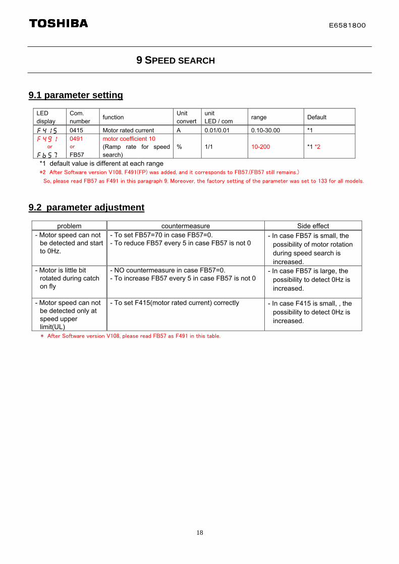
9 SPEED SEARCH
9.1 parameter setting
LED display
Com. number
function Unit convert
unit LED / com
range Default
f415 0415 Motor rated current A 0.01/0.01 0.10-30.00 *1
f491 or
fb57
0491 or
FB57
motor coefficient 10 (Ramp rate for speed search)
% 1/1 10-200 *1 *2
*1 default value is different at each range *2 After Software version V108, F491(FP) was added, and it corresponds to FB57.(FB57 still remains.)
So, please read FB57 as F491 in this paragraph 9. Moreover, the factory setting of the parameter was set to 133 for all models.
9.2 parameter adjustment
* After Software version V108, please read FB57 as F491 in this table.
problem countermeasure Side effect - Motor speed can not
be detected and start to 0Hz.
- To set FB57=70 in case FB57=0. - To reduce FB57 every 5 in case FB57 is not 0
- In case FB57 is small, the possibility of motor rotation during speed search is increased.
- Motor is little bit rotated during catch on fly
- NO countermeasure in case FB57=0. - To increase FB57 every 5 in case FB57 is not 0
- In case FB57 is large, the possibility to detect 0Hz is increased.
- Motor speed can not be detected only at speed upper limit(UL)
- To set F415(motor rated current) correctly - In case F415 is small, , the possibility to detect 0Hz is increased.

E6581800
19
9.3 The sequence of speed search
400ms
[100%/div]
Blue: control mode
Gree: motor current
[100%/div]
[50Hz/div]
Pink: Bus voltage
Red: stator frequency
Normal run MOFF state de- low-flux normal running fluxing start
Sp
eed
電源遮断 復電 MS リレー ON
De-fluxing: - wait 300ms just after MS relay is ON - in case gate block time is less than “FB71+300ms”,
wait until the total waiting time is “FB71+300ms” Speed search: Initial voltage is that frequency is “FH+5Hz”, flux is 1/7 of rated flux The ACC/DEC time is 0.5sec(0Hz to VL) (if FB57 is not 0, (0.5*100/FB57)sec). The frequency is reduced from “FH+5Hz” to 0Hz to “-FH-5Hz” , and torque current is detected during frequency transition. The point that the polarity of torque current is changed, it is estimated as “motor speed”.
V106or before
V108
INV FB57F491
or FB57x001 -x007
0(100) 133
x015 50 133x022 55 133x037 70 133
x:2:200VClass
Low-flux start: (PT=0,1,2)
- The motor is driven at “estimated speed” for the time “FB71*1.5” - The flux is increased during the drive from 1/4 of rated flux to rated flux
(PT=3,4) - The motor is driven at “estimated speed” for the time “FB71” - The flux is increased during the drive from 1/2 of rated flux to rated flux
E6581800
20
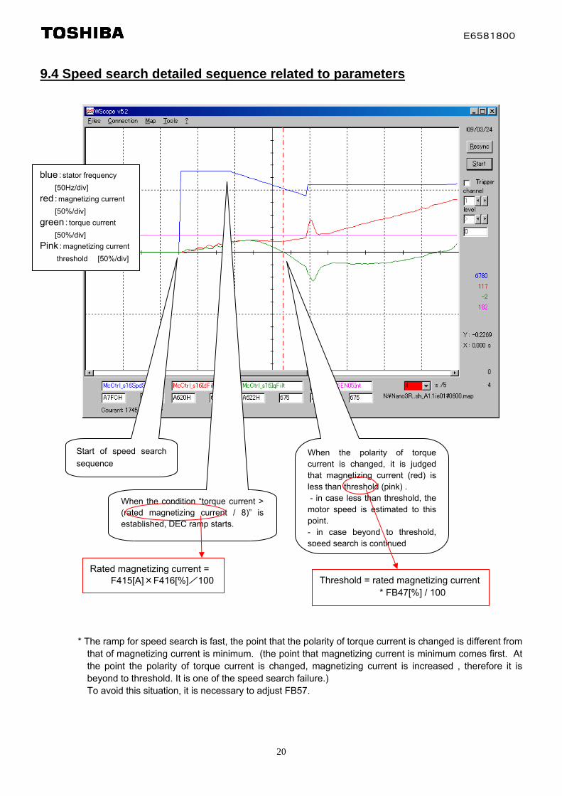
9.4 Speed search detailed sequence related to parameters
blue:stator frequency
[50Hz/div]
red:magnetizing current
[50%/div]
green:torque current
[50%/div]
Pink:magnetizing current
threshold [50%/div]
Start of speed search
sequence
When the condition “torque current > (rated magnetizing current / 8)” is established, DEC ramp starts.
When the polarity of torque current is changed, it is judged that magnetizing current (red) is less than threshold (pink) . - in case less than threshold, the motor speed is estimated to this point. - in case beyond to threshold, speed search is continued
Rated magnetizing current = F415[A]×F416[%]/100 Threshold = rated magnetizing current
* FB47[%] / 100 * The ramp for speed search is fast, the point that the polarity of torque current is changed is different from
that of magnetizing current is minimum. (the point that magnetizing current is minimum comes first. At the point the polarity of torque current is changed, magnetizing current is increased , therefore it is beyond to threshold. It is one of the speed search failure.) To avoid this situation, it is necessary to adjust FB57.
E6581800
21
10 CARRIER FREQUENCY
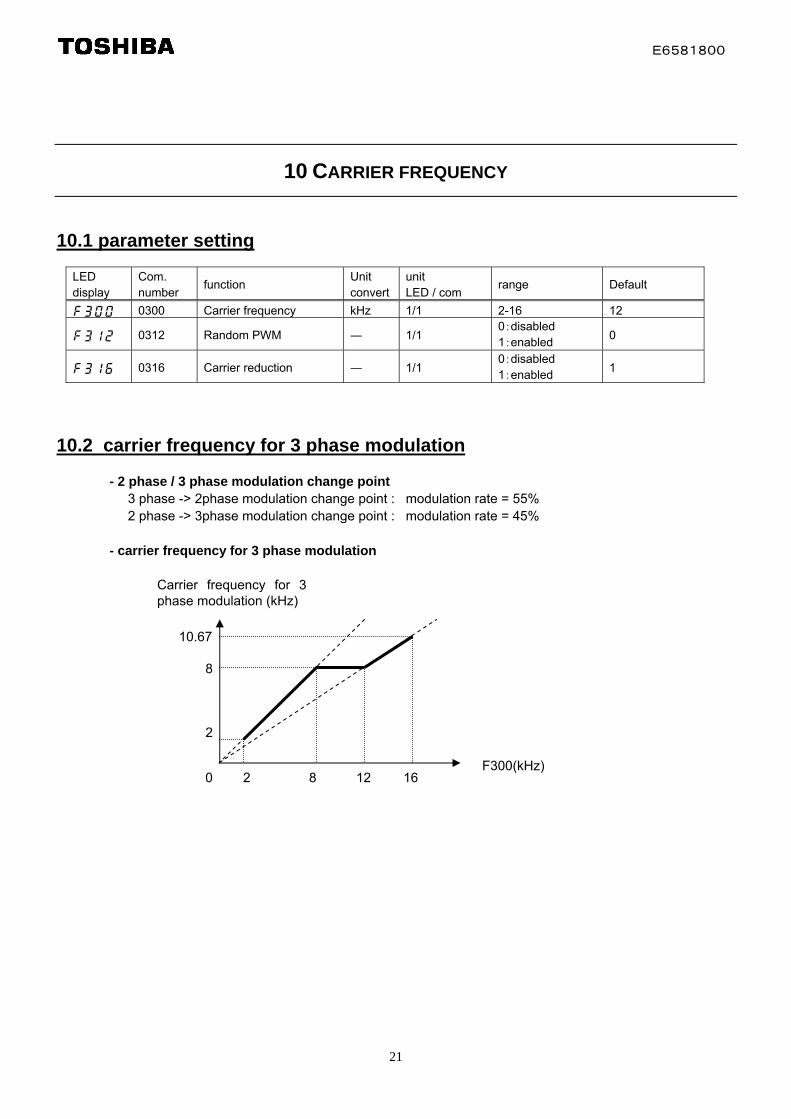
10.1 parameter setting
LED display
Com. number
function Unit convert
unit LED / com
range Default
f300 0300 Carrier frequency kHz 1/1 2-16 12
f312 0312 Random PWM ― 1/1 0:disabled 1:enabled
0
f316 0316 Carrier reduction ― 1/1 0:disabled 1:enabled
1
10.2 carrier frequency for 3 phase modulation
- 2 phase / 3 phase modulation change point 3 phase -> 2phase modulation change point : modulation rate = 55% 2 phase -> 3phase modulation change point : modulation rate = 45% - carrier frequency for 3 phase modulation
Carrier frequency for 3 phase modulation (kHz)
10.67
8
2
F300(kHz) 0 2 8 12 16
E6581800
22
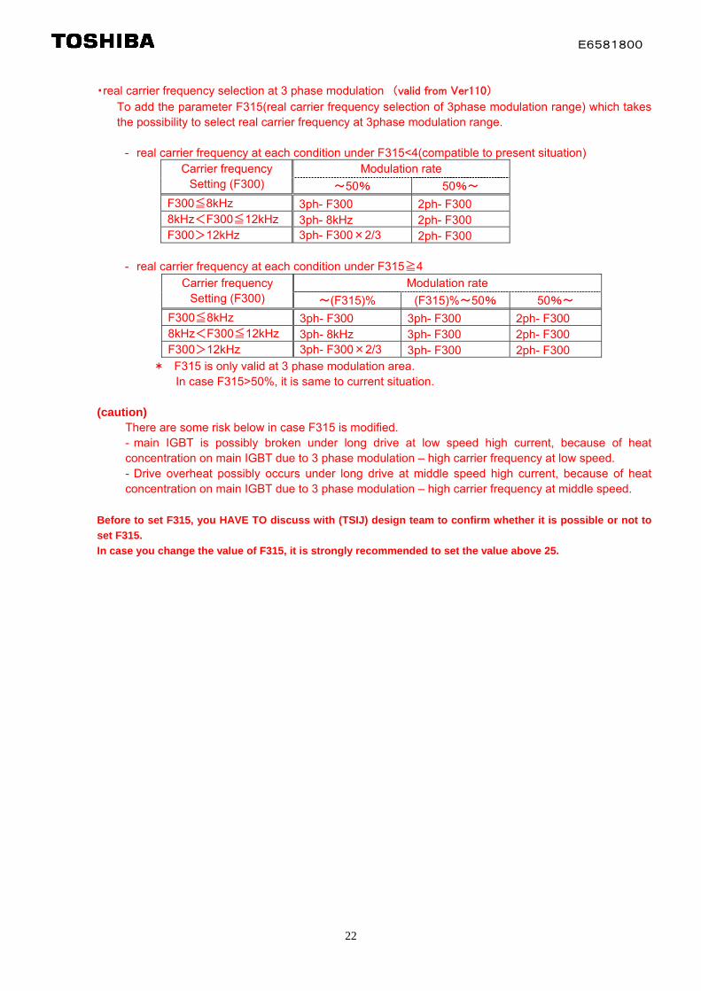
・real carrier frequency selection at 3 phase modulation (valid from Ver110)
To add the parameter F315(real carrier frequency selection of 3phase modulation range) which takes the possibility to select real carrier frequency at 3phase modulation range. - real carrier frequency at each condition under F315<4(compatible to present situation)
Modulation rate Carrier frequency Setting (F300) ~50% 50%~
F300≦8kHz 3ph- F300 2ph- F300 8kHz<F300≦12kHz 3ph- 8kHz 2ph- F300 F300>12kHz 3ph- F300×2/3 2ph- F300
- real carrier frequency at each condition under F315≧4
Modulation rate Carrier frequency Setting (F300) ~(F315)% (F315)%~50% 50%~
F300≦8kHz 3ph- F300 3ph- F300 2ph- F300 8kHz<F300≦12kHz 3ph- 8kHz 3ph- F300 2ph- F300 F300>12kHz 3ph- F300×2/3 3ph- F300 2ph- F300
* F315 is only valid at 3 phase modulation area. In case F315>50%, it is same to current situation.
(caution)
There are some risk below in case F315 is modified. - main IGBT is possibly broken under long drive at low speed high current, because of heat concentration on main IGBT due to 3 phase modulation – high carrier frequency at low speed. - Drive overheat possibly occurs under long drive at middle speed high current, because of heat concentration on main IGBT due to 3 phase modulation – high carrier frequency at middle speed.
Before to set F315, you HAVE TO discuss with (TSIJ) design team to confirm whether it is possible or not to
set F315.
In case you change the value of F315, it is strongly recommended to set the value above 25.

E6581800
23
10.3 carrier frequency at synchronized PWM
Start frequency of synchronized PWM : 105Hz End frequency of synchronized PWM : 95Hz
The relation between carrier frequency and stator frequency at synchronized PWM
- synchronized PWM means that carrier frequency depends on stator frequency that these relation is “carrier frequency = n * stator frequency (n is integer)”. - In case stator frequency is beyond to “start frequency”, synchronous PWM is enabled. - In case stator frequency is less than “end frequency”, synchronous PWM is disabled. - In case “stator frequency * 24” is beyond to upper limit of carrier frequency, carrier frequency
transits as “carrier frequency = stator frequency * 23, 22, 21… “ - In case “stator frequency * 12” is beyond to upper limit of carrier frequency, carrier frequency
transits as “carrier frequency = stator frequency * 12“
0
2000
4000
6000
8000
10000
12000
14000
16000
18000
0 100 200 300 400 500 600 700 800
Stator frequency (Hz)
PW
M f
requency
(Hz)
2kHz
4kHz
8kHz
12kHz
16kHz
f_start = 100Hz Fpwm_limit = 16kHz (no limitation)
0
2000
4000
6000
8000
10000
12000
14000
16000
18000
0 100 200 300 400 500 600 700 800
Stator frequency (Hz)
PW
M f
requency (
Hz)
2kHz
4kHz
8kHz
12kHz
16kHz
f_start = 100Hz Fpwm_limit = 8kHz (with limitation)

E6581800
24
10.4 carrier frequency reduction
In case F316=1, carrier frequency is reduced under the condition below. - The temperature of inverter heat sink is beyond 80 degree C (depend on carrier frequency as below).
キャリア周波数 高温時(2015)
1
2
3
4
5
6
7
8
9
10
11
12
13
14
15
16
17
70 80 90 100
温度モニタ FE83 (℃) →
実効
キャ
リア
周波
数 _uiP
wm
Fre
qen
cyE
nt
(kH
z)→
F300=16kHz F300=12kHz F300=8kHz F300=6kHz F300=4kHz F300=2kHz
- The estimated temperature rising is beyond to 45 degree C for inverter IGBT. Carrier frequency is reduced the estimation is lower than 45 degree C
キャリア周波数 高温時(2007)
1
2
3
4
5
6
7
8
9
10
11
12
13
14
15
16
17
70 80 90
温度モニタ FE83 (℃) →
実効
キャ
リア
周波
数 _uiP
wm
Fre
qen
cyE
nt
(kH
z) →
100
F300=16kHz F300=12kHz F300=8kHz F300=6kHz F300=4kHz F300=2kHz

E6581800
25
11 OVER TORQUE TRIP
11.1 parameter setting
LED display
function Unit / selection note
0:alarm Output TB 28,29 F615 Over torque trip / alarm selection 1:trip OT blink display
F616 Over torque detection level 0.01% 0 means disabled the function
F618 Over torque detection time 0.1s 0 means fastest(4ms) detection
F619 Hysteresis of over torque detection level
0.01%
11.2 detection level
- over torque trip(alarm) level = F616 - over torque trip(alarm) recover level = F616 – F619
11.3 details of detection
The time that motor torque (12ms filtered) is beyond to “over torque trip(alarm) level” is cumulated. The cumulated time is beyond to “over torque detection time (F618)”, over torque trip or alarm is output. Alarm is output in case F615=0, “OT” trip is output in case F615=1. In case that motor torque (12ms filtered) is less than “over torque trip(alarm) recover level” , the cumulated time is reset . The definition of rated torque
The rated torque[N.m] means “motor power[W] * 9.55 / motor synchronized speed[rpm]”. For example, in case the motor rate is 4pole-60Hz-3.7kW, Rated torque = 3700 * 9.55 / {60*120/4} = 19.63[N.m]
E6581800
26
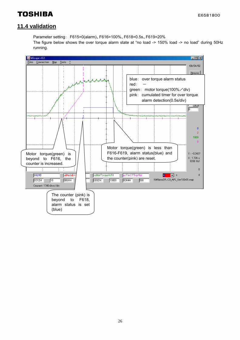
11.4 validation
Parameter setting: F615=0(alarm)、F616=100%、F618=0.5s、F619=20% The figure below shows the over torque alarm state at “no load -> 150% load -> no load” during 50Hz running.
alarm detection(0.5s/div)
Motor torque(green) is beyond to F616, the counter is increased.
Motor torque(green) is less than F616-F619, alarm status(blue) and the counter(pink) are reset.
The counter (pink) is beyond to F618, alarm status is set (blue)
blue: over torque alarm status red: - green: motor torque(100%/div) pink: cumulated timer for over torque

E6581800
27
12 DC INJECTION
12.1 parameter setting
LED display
Com. number
function Unit convert
unit LED / com
range Default
f250 0250 Motor control bits Hz 0.1 / 0.01 0.0-FH 0.0 f467 0467 Current differential gain - 1 / 1 0-100 10
12.2 parameter adjustment
problem countermeasure Side effect
- motor is little bit rotated to opposite direction
- To increase F250 every 0.5Hz up to rated slip frequency (in case F250 is small) - To reduce F467 every 5 (in case PT=0,1,2)
- The possibility that motor is little bit rotated to
forward direction is increased.
- refer to the section 3.3
In case the stator frequency just before DC injection is started is negative (opposite direction), it is kept during “reducing remaining voltage” the primary part of DC injection . It causes the problem.
E6581800
28
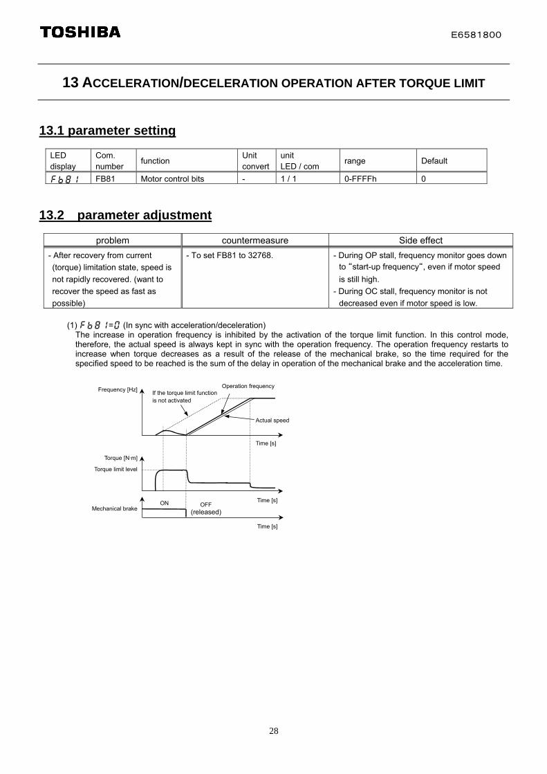
13 ACCELERATION/DECELERATION OPERATION AFTER TORQUE LIMIT
13.1 parameter setting
LED display
Com. number
function Unit convert
unit LED / com
range Default
fb81 FB81 Motor control bits - 1 / 1 0-FFFFh 0
13.2 parameter adjustment
problem countermeasure Side effect
- After recovery from current
(torque) limitation state, speed is
not rapidly recovered. (want to
recover the speed as fast as
possible)
- To set FB81 to 32768.
- During OP stall, frequency monitor goes down
to “start-up frequency“, even if motor speed
is still high.
- During OC stall, frequency monitor is not
decreased even if motor speed is low.
(1) fb81=0 (In sync with acceleration/deceleration) The increase in operation frequency is inhibited by the activation of the torque limit function. In this control mode, therefore, the actual speed is always kept in sync with the operation frequency. The operation frequency restarts to increase when torque decreases as a result of the release of the mechanical brake, so the time required for the specified speed to be reached is the sum of the delay in operation of the mechanical brake and the acceleration time.
Frequency [Hz]
Time [s]
Torque [N·m]
Time [s]
Torque limit level
Actual speed
If the torque limit functionis not activated
Operation frequency
Time [s]
Mechanical brakeON OFF
(released)

E6581800
29
(2) fb81=32768(In sync with min. time)
The operation frequency keeps increasing, even if the torque limit function is activated. In this control mode, the actual speed is kept in sync with the operation frequency, while torque is held at a limit level when it decreases as a result of the release of the mechanical brake. The use of this function prevents the load from failing and improves the motor’s response during inching operation.
Frequency [Hz]
Torque [N·m]
Torque limit level
Mechanical brake
Time [s]
Actual speed(Acceleration rates vary dependingon the torque limit level.)
Operation frequency
Time [s]
Time [s]
ON OFF(released)
Torque is held at a limit level evenafter the mechanical brake is released.