Operating instruction - Motor drive PXD compact - Movetec · Operating Instruction Motor drive PXD...
25
Operating Instruction Motor drive PXD compact Document no.: B-00021 Edition 2015 07 operating instruction EN Copyright by Ergoswiss AG 1/25 Operating instruction - Motor drive PXD compact to control and drive hydraulic lifting systems made by Ergoswiss AG It is essential to read this operating instruction thoroughly before commissioning the system. This operating instruction has to be stored in the immediate vicinity of the system. Motor drive PXD compact Power cable Control box PXD compact manual control switch D / Memory Motor cable PXD compact Motor PXD with front plate and PXD housing Cable strain relief PXD coupling for connection to the Ergoswiss hydraulic pumps type PA and PB (with Woodruff key) Errors and technical changes reserved. Ergoswiss AG does not assume any liability for operating errors or using the products outside of the specified normal use. At the time of delivery Ergoswiss AG will replace or re- pair defect products within accordance with the warran- ty provisions. In addition, Ergoswiss assumes no other liability. For your questions and special custom demand Ergoswiss AG will be at your disposal. Ergoswiss AG Nöllenstrasse 15 CH-9443 Widnau Tel.: +41 (0) 71 727 06 70 Fax: +41 (0) 71 727 06 79 [email protected] www.ergoswiss.com 1 3 2 4 5 7 6
Transcript of Operating instruction - Motor drive PXD compact - Movetec · Operating Instruction Motor drive PXD...

Operating Instruction Motor drive PXD compact
Document no.: B-00021
Edition 2015 07
operating instruction EN
Copyright by Ergoswiss AG
1/25
Operating instruction - Motor drive PXD compact
to control and drive hydraulic lifting systems made by Ergoswiss AG
It is essential to read this operating instruction thoroughly before commissioning the system. This operating instruction has to be stored in the immediate vicinity of the system.
Motor drive PXD compact
Power cable
Control box PXD compact
manual control switch D / Memory
Motor cable PXD compact
Motor PXD with front plate and PXD housing
Cable strain relief
PXD coupling for connection to the Ergoswiss
hydraulic pumps type PA and PB (with Woodruff key)
Errors and technical changes reserved.
Ergoswiss AG does not assume any liability for operating errors or using the products outside of the specified normal use.
At the time of delivery Ergoswiss AG will replace or re-pair defect products within accordance with the warran-ty provisions. In addition, Ergoswiss assumes no other liability.
For your questions and special custom demand Ergoswiss AG will be at your disposal.
Ergoswiss AG
Nöllenstrasse 15
CH-9443 Widnau
Tel.: +41 (0) 71 727 06 70
Fax: +41 (0) 71 727 06 79
www.ergoswiss.com
1
3
2
4
5
7
6
Operating Instruction Motor drive PXD compact
Document no.: B-00021
Edition 2015 07
operating instruction EN
Copyright by Ergoswiss AG
2/25
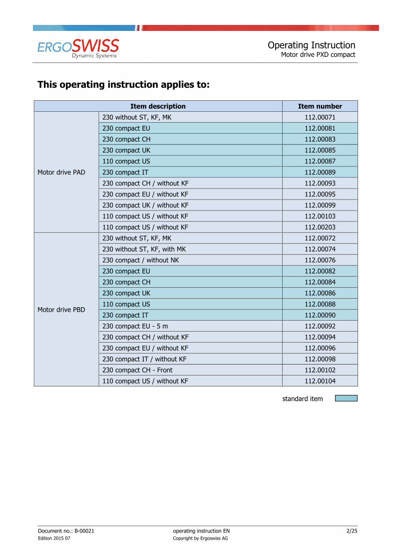
This operating instruction applies to:
Item description Item number
Motor drive PAD
230 without ST, KF, MK 112.00071
230 compact EU 112.00081
230 compact CH 112.00083
230 compact UK 112.00085
110 compact US 112.00087
230 compact IT 112.00089
230 compact CH / without KF 112.00093
230 compact EU / without KF 112.00095
230 compact UK / without KF 112.00099
110 compact US / without KF 112.00103
110 compact US / without KF 112.00203
Motor drive PBD
230 without ST, KF, MK 112.00072
230 without ST, KF, with MK 112.00074
230 compact / without NK 112.00076
230 compact EU 112.00082
230 compact CH 112.00084
230 compact UK 112.00086
110 compact US 112.00088
230 compact IT 112.00090
230 compact EU - 5 m 112.00092
230 compact CH / without KF 112.00094
230 compact EU / without KF 112.00096
230 compact IT / without KF 112.00098
230 compact CH - Front 112.00102
110 compact US / without KF 112.00104
standard item

Operating Instruction Motor drive PXD compact
Document no.: B-00021
Edition 2015 07
operating instruction EN
Copyright by Ergoswiss AG
3/25
Table of contents
1 Product description ................................................................................................................. 4
1.1 General .................................................................................................................................. 4
1.2 Specified normal operation ...................................................................................................... 4
1.3 Target group and prior knowledge ........................................................................................... 4
1.4 Performance characteristics ..................................................................................................... 5
1.4.1 Control box PXD compact .................................................................................................... 5
1.4.2 Manual control switch D / Memory ....................................................................................... 5
1.4.3 PXD motor .......................................................................................................................... 5
2 Safety requirements ................................................................................................................ 6
2.1 Explanations of the symbols and notes ..................................................................................... 6
2.2 Basic safety instructions .......................................................................................................... 7
3 Installation information .......................................................................................................... 8
3.1 Mounting instruction of the control box .................................................................................... 8
3.2 Mounting instructions of the manual control switch ................................................................... 9
3.3 Installation of the PXD housing ................................................................................................ 9
4 Initial operation ..................................................................................................................... 10
4.1 Cable connections ................................................................................................................. 10
4.2 Initial operation .................................................................................................................... 13
5 Operation with the manual control switch D / Memory ........................................................ 14
5.1 Drive up/down ...................................................................................................................... 14
5.2 Setting the shown height on the display ................................................................................. 14
5.3 Saving a memory position ...................................................................................................... 15
5.4 Approaching a stored position ................................................................................................ 15
5.5 Reset of the control box ........................................................................................................ 16
5.6 Duty cycle monitoring ............................................................................................................ 16
6 Operation with other manual control switchs ....................................................................... 17
6.1 Initial operation .................................................................................................................... 17
6.2 Drive up/down ...................................................................................................................... 17
7 Synchronous operation of 2, 3 or 4 control boxes................................................................. 18
7.1 Cable connections ................................................................................................................. 18
7.2 Commissioning the synchronized systems ............................................................................... 19
7.3 Operation scenarios - FAQ ..................................................................................................... 20
Safety strip - Squeezing protection ............................................................................................. 21
7.4 Technical Data ...................................................................................................................... 21
7.5 Connecting the safety strip .................................................................................................... 22
8 Maintenance and disposal ..................................................................................................... 23
8.1 Maintenance and cleaning ..................................................................................................... 23
8.2 Error messages on the display ............................................................................................... 24
8.3 Click codes ........................................................................................................................... 25
8.4 Trouble-shooting ................................................................................................................... 25
8.5 Repairs and spare parts ......................................................................................................... 25
8.6 Disassembly and disposal ...................................................................................................... 25

Operating Instruction Motor drive PXD compact
Document no.: B-00021
Edition 2015 07
operating instruction EN
Copyright by Ergoswiss AG
4/25
1 Product description
1.1 General
The basic functionality of a hydraulic lifting system by Ergoswiss AG (“motor drive pump tubing
cylinder“) is the lifting, lowering and tilting of work surfaces, machine parts, profile systems etc.
All Ergoswiss hydraulic lifting systems with the pump types PA-W and PB-W (W = woodruff key) can be
driven by the motor drive PXD compact. The motor drive PXD compact consists of a motor PXD, a control box PXD compact, a manual control switch D / Memory, different connection cables and a plastic housing.
The intelligent control box PXD compact is equipped with a highly efficient switched-mode power supply (SMPS) and a monitoring software. Due to the optimised driving comfort, the end positions are gently ap-
proached as low-speed zones up to the standstill. Additional functions, such as the synchronisation of two to
four drives, ISP collision protection (Intelligent System Protection), or the connection of safety strips (squeezing protection) can be used.
With the manual control switch D / Memory the hydraulic system can be operated comfortably, the work surface will be adjusted steplessly in its height. The current height of the work surface is continuously shown
on the display of the manual control switch (cm or inches). Up to four different memory positions can be stored and approached individually.
1.2 Specified normal operation
The motor drive PXD compact is exclusively intended to control and drive Ergoswiss AG hydraulic lifting sys-tems. To do so the specified normal operation of the entire system is to be complied with.
The system is only to be installed and used indoors in dry conditions. The operating temperature range is at 0° C to +40° C.
The motor drive PXD compact must not be overloaded. Do not exceed the given maximum lifting loads of
the hydraulic lifting systems.
The motor drive PXD compact can be continuously operated for a maximum of 2 minutes. Afterwards a
pause of at least 18 minutes needs to be observed before the system can be operated again. To avoid over-heating of the system a duty cycle of 2/18 (ON/OFF) should be maintained in general.
1.3 Target group and prior knowledge
This operating instruction addresses the following groups of people:
The commissioning staff, who install and commission the motor drive PXD compact and the Ergoswiss AG
hydraulic system as an incomplete assembly into a work station, a machine, ect. For commissioning activi-ties, mechanical and electrical knowledge is prerequisite. Before using the system for the first time the oper-
ating instruction must be read.
The end user controls the complete system via manual control switch and adjusts its height.
Before using the system for the first time the operating instruction must be read.
Operating Instruction Motor drive PXD compact
Document no.: B-00021
Edition 2015 07
operating instruction EN
Copyright by Ergoswiss AG
5/25
1.4 Performance characteristics
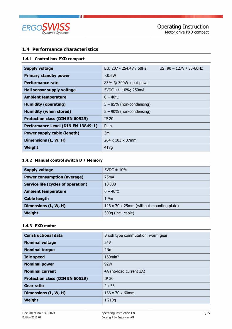
1.4.1 Control box PXD compact
Supply voltage EU: 207 - 254.4V / 50Hz US: 90 – 127V / 50-60Hz
Primary standby power <0.6W
Performance rate 83% @ 300W input power
Hall sensor supply voltage 5VDC +/- 10%; 250mA
Ambient temperature 0 – 40℃
Humidity (operating) 5 – 85% (non-condensing)
Humidity (when stored) 5 – 90% (non-condensing)
Protection class (DIN EN 60529) IP 20
Performance Level (DIN EN 13849-1) PL b
Power supply cable (length) 3m
Dimensions (L, W, H) 264 x 103 x 37mm
Weight 418g
1.4.2 Manual control switch D / Memory
Supply voltage 5VDC ± 10%
Power consumption (average) 75mA
Service life (cycles of operation) 10‘000
Ambient temperature 0 – 40℃
Cable length 1.9m
Dimensions (L, W, H) 126 x 70 x 25mm (without mounting plate)
Weight 300g (incl. cable)
1.4.3 PXD motor
Constructional data Brush type commutation, worm gear
Nominal voltage 24V
Nominal torque 2Nm
Idle speed 160min-1
Nominal power 92W
Nominal current 4A (no-load current 3A)
Protection class (DIN EN 60529) IP 30
Gear ratio 2 : 53
Dimensions (L, W, H) 166 x 70 x 60mm
Weight 1’210g

Operating Instruction Motor drive PXD compact
Document no.: B-00021
Edition 2015 07
operating instruction EN
Copyright by Ergoswiss AG
6/25
2 Safety requirements
2.1 Explanations of the symbols and notes
Please pay attention to the following explanations of the symbols and notes. They are classified according to
ISO 3864-2.
DANGER
Indicates an immediate threatening danger.
Non-compliance with this information can result in death or serious personal injuries (invalid-ity).
WARNING
Indicates a possible dangerous situation.
Non-compliance with this information can result in death or serious personal injuries (invalid-
ity).
ATTENTION
Indicates a possible dangerous situation.
Non-compliance with this information can result in damage to property or light to medium
personal injuries.
NOTE
Indicates general notes, useful operator advice and operating recommendations which do
not affect safety and health of the user.
Operating Instruction Motor drive PXD compact
Document no.: B-00021
Edition 2015 07
operating instruction EN
Copyright by Ergoswiss AG
7/25
2.2 Basic safety instructions
The safety instructions must be paid attention to. If the system is operated improperly, it can cause danger to people and objects!
It is essential to read this operating instruction thoroughly before commissioning the system. This operating instruction has to be stored in the immediate vicinity of the system.
In no case the control box may be opened! There is the risk of an electrical shock.
Modifications or changes to the control box, the manual control switch, the motor and any connection
cables are forbidden!
The control box must only be operated with mains voltage indicated on the name plate!
The supplied power cable must be used. It is forbidden to operate the control box with a damaged
power cable!
Electrical cables must not be exposed to crushing hazard or to bending and tensile loads.
Before connecting/disconnecting the manual control switch the power cable has to be disconnected
from the mains!
The control box must not be operated in a potentially explosive atmosphere!
The control box must be protected from moisture, dripping water as well as spray water!
The control box is not suitable for continuous use. The operation/hold ratio must not exceed 2/18.
If there is a failure (for example, if the control drives on its own, or if a push button is stuck) the power
cable is to be separated from the mains immediately! The power cable must be freely accessible at any
time.
While using the height adjustment of the work surface there is a danger of squeezing. It is important to
make sure that no objects or people are within the danger zone and no one is reaching into the danger zone.
This device is not intended to be used by people (including children under 8) with restricted physical,
sensory or mental abilities or with a lack of experience and/or knowledge, unless they are supervised by a person responsible for safety or they have received instructions by this very person on how to operate
the device.
Children under 8 should be supervised to ensure that they do not play with the device.
If the power cable of the drive is damaged it must be replaced by the manufacturer, the manufacturer's
customer service or by a similar qualified person.
Only use a dry or a damp cloth to clean the control box! Before cleaning, the power cable has to be
separated from the mains!

Operating Instruction Motor drive PXD compact
Document no.: B-00021
Edition 2015 07
operating instruction EN
Copyright by Ergoswiss AG
8/25
3 Installation information
Before commissioning the motor drive PXD compact, the whole hydraulic lifting system must be assembled
correctly according to the assembly instructions.
The control box must be mounted in the close distance of the motor (motor is connected to the pump). The
motor cable PXD, connecting the control box to the motor, has a length of 950mm. If needed, up to 5 motor extension cables can be connected. They have a length of 1’200mm.
124.00137: PXD compact motor extension cable 1’200mm
The manual control switch D / Memory must be mounted close to the control box and be easily accessible. The cable of the manual control switch has a length of 1’900mm, and if needed it can be expanded with up
to 3 extension cables. They have a length of 1’000mm.
124.00071: PXD manual control switch extension cable 1’000mm
3.1 Mounting instruction of the control box
Mounting of the control box PXD compact underneath a table top:
ATTENTION
During mounting of the control box PXD compact the power cable needs to be disconnected
from the mains!
1. Place the control box to the desired location and mark the drill holes with a pen.
2. Pre-drill two holes (Ø 3mm).
Be careful not to drill through the table top!
3. The control box is mounted with two screws (cap screws DIN7981C 4.8xL, cap-Ø 9.5mm).
NOTE
When tightening the screws do not exceed a maximum torque of 2Nm!
Operating Instruction Motor drive PXD compact
Document no.: B-00021
Edition 2015 07
operating instruction EN
Copyright by Ergoswiss AG
9/25
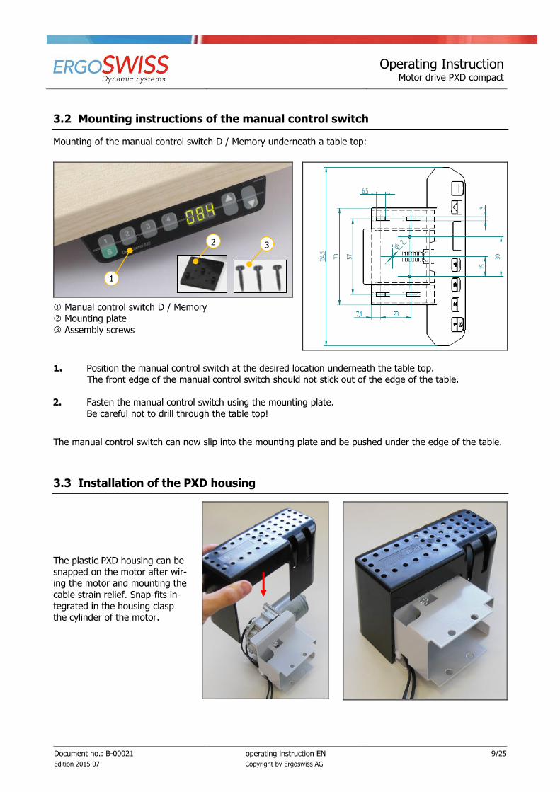
3.2 Mounting instructions of the manual control switch
Mounting of the manual control switch D / Memory underneath a table top:
Manual control switch D / Memory
Mounting plate Assembly screws
1. Position the manual control switch at the desired location underneath the table top.
The front edge of the manual control switch should not stick out of the edge of the table.
2. Fasten the manual control switch using the mounting plate.
Be careful not to drill through the table top!
The manual control switch can now slip into the mounting plate and be pushed under the edge of the table.
3.3 Installation of the PXD housing
The plastic PXD housing can be
snapped on the motor after wir-ing the motor and mounting the
cable strain relief. Snap-fits in-
tegrated in the housing clasp the cylinder of the motor.
1
2 3

Operating Instruction Motor drive PXD compact
Document no.: B-00021
Edition 2015 07
operating instruction EN
Copyright by Ergoswiss AG
10/25
4 Initial operation
4.1 Cable connections
ATTENTION
The power cable must not be connected to the mains while connecting all motor cables and the manual control switch cable!
The control box PXD compact is equipped with the following connectors:
Motor socket 1 (M1)
Motor socket 2 (M2)
(S) Socket for manual control switch
(D) Connection for safety strip or sync cable
(P) Power socket
(F) Connection for grounding the table frame
ATTENTION
Connecting homemade products to the control box is prohibited!
Only supplied components are to be used, otherwise the danger of damage or destruction of
the device can arise.
1
2
S
GB
P F

Operating Instruction Motor drive PXD compact
Document no.: B-00021
Edition 2015 07
operating instruction EN
Copyright by Ergoswiss AG
11/25
1. Connect plugs A and B of the motor cable PXD to the motor.
PXD motor cable
NOTE
Plug A must be connected to the motor in a way its cable shows in the direction of the gear
shaft (in the direction of the arrow).
2. Place both lines of the motor cable into the cable strain relief. The bendable tab of the cable strain
relief should point towards the motor. The distance between cable strain relief and the connectors
A+B should be approx. 140mm.
3. Firmly compress the cable strain relief while inserting it into the slot of the motor front panel.
A B
A B
M1
M2

Operating Instruction Motor drive PXD compact
Document no.: B-00021
Edition 2015 07
operating instruction EN
Copyright by Ergoswiss AG
12/25
4. Connect the motor cable to the control box. The continuous cable must be plugged into the motor
socket M1, the split cable must be plugged into the motor socket M2.
5. Connect the manual control switch D / Memory to the control box.
NOTE
The drive does not work, if the motor cable plugs are connected to the wrong socket.
6. Connect optional components (sync cable, safety strip, ect.) exact descriptions can be found in the following chapters!
7. Fasten all slack cables to avoid cables from entanglement.
8. Connect the power cable to the control box.
9. Connect the power cable to the mains.
(Clicking sound of the control box ready for initial operation)
NOTE
Before connecting the power cable to the mains the following must be verified:
Does the mains voltage correspond to the value on the name plate of the control box?
Are the plugs of the motor cable connected to the correct sockets (M1, M2)?
Is the entire hydraulic lifting system assembled according to the assembly instructions?
Split cable
M1
M2
connect optional compo-nents
Operating Instruction Motor drive PXD compact
Document no.: B-00021
Edition 2015 07
operating instruction EN
Copyright by Ergoswiss AG
13/25
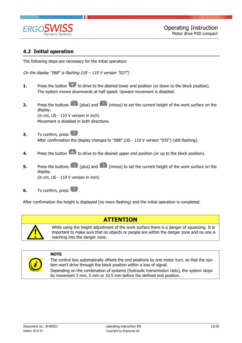
4.2 Initial operation
The following steps are necessary for the initial operation:
On the display "068" is flashing (US – 110 V version "027")
1. Press the button to drive to the desired lower end position (or down to the block position).
The system moves downwards at half speed. Upward movement is disabled.
2. Press the buttons 1
(plus) and 2
(minus) to set the current height of the work surface on the display.
(in cm, US - 110 V version in inch)
Movement is disabled in both directions.
3. To confirm, press S .
After confirmation the display changes to "088" (US - 110 V version "035") (still flashing).
4. Press the button to drive to the desired upper end position (or up to the block position).
5. Press the buttons 1
(plus) and 2
(minus) to set the current height of the work surface on the display.
(in cm, US - 110 V version in inch)
6. To confirm, press S .
After confirmation the height is displayed (no more flashing) and the initial operation is completed.
ATTENTION
While using the height adjustment of the work surface there is a danger of squeezing. It is important to make sure that no objects or people are within the danger zone and no one is
reaching into the danger zone.
NOTE
The control box automatically offsets the end positions by one motor turn, so that the sys-
tem won’t drive through the block position within a loss of signal.
Depending on the combination of systems (hydraulic transmission ratio), the system stops
its movement 3 mm, 5 mm or 10.5 mm before the defined end position.
Operating Instruction Motor drive PXD compact
Document no.: B-00021
Edition 2015 07
operating instruction EN
Copyright by Ergoswiss AG
14/25
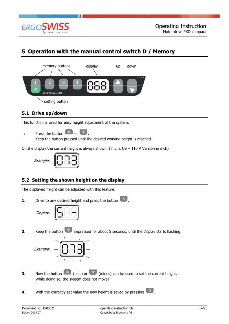
5 Operation with the manual control switch D / Memory
Antrieb
Auf AbPositionstasten
Speichertaste
LO G IC DA TA
1
S
2 3 4
Desk Control 520
Display
5.1 Drive up/down
This function is used for easy height adjustment of the system.
Press the button or .
Keep the button pressed until the desired working height is reached.
On the display the current height is always shown. (in cm, US – 110 V Version in inch)
Example:
5.2 Setting the shown height on the display
The displayed height can be adjusted with this feature.
1. Drive to any desired height and press the button S
.
Display:
2. Keep the button impressed for about 5 seconds, until the display starts flashing.
Example:
3. Now the button (plus) or (minus) can be used to set the current height.
While doing so, the system does not move!
4. With the correctly set value the new height is saved by pressing S
.
memory buttons display up down
setting button

Operating Instruction Motor drive PXD compact
Document no.: B-00021
Edition 2015 07
operating instruction EN
Copyright by Ergoswiss AG
15/25
5.3 Saving a memory position
With this function it is possible to memorise a certain position/height and approach it at a later time by pushing one button. With the four memory buttons up to four different positions can be stored and ap-
proached.
1. Drive to the desired position and press the button S
.
Display:
2. Press one of the buttons 1 2 3 4
.
After pressing a memory button the display shows "S" and the number of the pressed button.
Example:
After saving there is a double click sound, and after approx. 2 seconds the current height is displayed again.
Example:
This operation can be repeated as often as you like and on any position.
5.4 Approaching a stored position
This function is designed to approach a stored position. Saving a position, see chapter 5.3.
Press one of the buttons 1 2 3 4
. The system approaches and stops at the stored position.
The system stops moving when releasing the button.
Pressing any other button while approaching the position will stop the system!

Operating Instruction Motor drive PXD compact
Document no.: B-00021
Edition 2015 07
operating instruction EN
Copyright by Ergoswiss AG
16/25
5.5 Reset of the control box
When resetting the control box all saved memory- and end positions will be deleted. After reset the initial operation must be redone according to chapter 4.2.
1. Press the buttons 1
, 2
and simultaneously, until “S 5“ or “S 7“ is displayed. The control is now set to initial operation mode.
2. Press the button until “S 7“ appears on the display.
3. Press the button S .
On the display “068“ is flashing carry out initial operation according to chapter 4.2.
5.6 Duty cycle monitoring
The duty cycle monitoring checks for the operation/hold ratio. To avoid overheating of the system a duty cycle of 2/18 (ON/OFF) should be maintained.
The maximum continuous operating time is 2 minutes. Afterwards a pause of at least 18 minutes needs to be observed before the system can be operated again.

Operating Instruction Motor drive PXD compact
Document no.: B-00021
Edition 2015 07
operating instruction EN
Copyright by Ergoswiss AG
17/25
6 Operation with other manual control switchs
Alternatively to the manual control switch D / Memory, the motor drive PXD compact can also be operated
with the following up/down manual control switchs.
Manual control switch D / up-down
124.00052
Manual control switch D / Front
124.00059
Manual control switch D / A+B
124.00063
6.1 Initial operation
The following steps are necessary for the initial operation:
1. Press the button to drive to the desired lower end position (or down to the block position).
The system moves downwards at half speed. Upward movement is disabled.
2. Press the button and simultaneously.
Hold the buttons for about 5 seconds.
3. Press the button to drive to the desired upper end position (or up to the block position).
4. Press the button and simultaneously.
Hold the buttons for about 5 seconds.
NOTE
A reset of the control box cannot be carried out using the above mentioned manual control
switchs. To do so, the manual control switch D / Memory must be used, or the software must be reloaded onto the control box.
6.2 Drive up/down
This function is used for simple height adjustment of the system.
Press the button or .
Hold the button down until the desired working height is reached.
Operating Instruction Motor drive PXD compact
Document no.: B-00021
Edition 2015 07
operating instruction EN
Copyright by Ergoswiss AG
18/25
7 Synchronous operation of 2, 3 or 4 control boxes
7.1 Cable connections
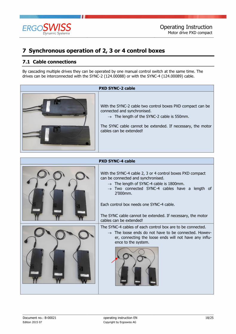
By cascading multiple drives they can be operated by one manual control switch at the same time. The drives can be interconnected with the SYNC-2 (124.00088) or with the SYNC-4 (124.00089) cable.
PXD SYNC-2 cable
With the SYNC-2 cable two control boxes PXD compact can be
connected and synchronised.
The length of the SYNC-2 cable is 550mm.
The SYNC cable cannot be extended. If necessary, the motor cables can be extended!
PXD SYNC-4 cable
With the SYNC-4 cable 2, 3 or 4 control boxes PXD compact can be connected and synchronised.
The length of SYNC-4 cable is 1800mm.
Two connected SYNC-4 cables have a length of
2’000mm.
Each control box needs one SYNC-4 cable.
The SYNC cable cannot be extended. If necessary, the motor cables can be extended!
The SYNC-4 cables of each control box are to be connected.
The loose ends do not have to be connected. Howev-
er, connecting the loose ends will not have any influ-ence to the system.

Operating Instruction Motor drive PXD compact
Document no.: B-00021
Edition 2015 07
operating instruction EN
Copyright by Ergoswiss AG
19/25
7.2 Commissioning the synchronized systems
1. Wire the drives according to chapter 4.1.
2. Connect the control boxes using the PXD SYNC-2 cable for two control boxes, or the PXD SYNC-4 cable for 2, 3 or 4 control boxes.
3. Only one manual control switch is necessary. The control box with the manual control switch is the master control box. All other control boxes are subordinated.
4. Connect the control boxes to the mains.
(Clicking sound of the control box ready for initial operation)
5. Carry out the initial operation according to chapter 4.2.
ATTENTION
The SYNC cable must be connected to the control box before the control box is connected to the mains. If the SYNC cables are connected afterwards, they will not be recognised by the
control box and only one drive will move, which can lead to jamming of the entire system.

Operating Instruction Motor drive PXD compact
Document no.: B-00021
Edition 2015 07
operating instruction EN
Copyright by Ergoswiss AG
20/25
7.3 Operation scenarios - FAQ
Scenario: connecting the manual control switch to another control box
Display blinks (- - -) Manual control switch doesn’t work
Manual control switch ONLY works on the the master control box
Scenario: disconnecting or reconnecting the synchronisation cable
Display blinks (000) Then display blinks (E93) Do a „S 0“ (all control boxes will be set to default setting)
1. Press the buttons 1
, 2
and simultaneously, until “S 5“ or “S 7“ is displayed. The control is now set to initial operation mode.
2. Press the button until “S 0“ appears on the display.
3. Press the button S .
On the display “068“ is flashing carry out initial operation according to chapter 4.2.
Scenario: power cut
Control box saves all stored positions
Synchronisation is stored
Getting back the power, the system can be used as usual. No initial operation necessary.
Scenario: power cut on only one control box
Display blinks (000) Then display blinks (E93) Do a „S 0“ (all control boxes will be set to default setting)
1. Press the buttons 1
, 2
and simultaneously, until “S 5“ or “S 7“ is displayed. The control is now set to initial operation mode.
2. Press the button until “S 0“ appears on the display.
3. Press the button S .
On the display “068“ is flashing carry out initial operation according to chapter 4.2.
NOTE
Putting the control boxes into default setting “S 0” can be done at any time. After doing a “S 0” all control boxes are equal – there is no master control box anymore.
After doing a “S 0” all synchronisation cables and manual control switches can be discon-
nected and reconnected as wished.
Are all cables connected there must be done an initial operation.

Operating Instruction Motor drive PXD compact
Document no.: B-00021
Edition 2015 07
operating instruction EN
Copyright by Ergoswiss AG
21/25
Safety strip - Squeezing protection
With hydraulic lifting systems of Ergoswiss AG it is important to make sure that no objects or people are
trapped during a stroke. ->Danger of squeezing
Attach the safety strip to an assumed squeeze zone. If the safety strip gets squeezed while the system is do-
ing a downward movement, the motor will stop instantly and turn back for one motor turn.
Depending on the combination of systems (hydraulic transmission ratio), the system stops its movement
3mm, 5mm or 10.5mm before the defined end position.
NOTE
The standard control box software V200 detects the safety strip function only when driving
the system downwards. The control box can be specifically programmed for a safety strip function in an upward movement, or in both directions of travel.
The safety strip 124.00105 consists of:
7.4 Technical Data
Functional properties of the contact tube
Contact angle < 80°
Switching pressure < 25 N at 23 °C
Switching travel < 2mm at 23 °C
Bending radii minimal B1 120mm / B2 150mm /
B3 20mm / B4 20mm
Max. tensile load 20 N
Electrical properties
Terminal resistance 2.2 kOhm
Max. switching capacity 250 mW
Max. Voltage DC 24 V
Current min/max 1mA / 10mA
Adapter cable sadety strip comp.
124.00106
End piece with cable / RJ45
124.00107
Contact tube
124.00101
End piece with
resistor 2.2kΩ
124.00118
185mm 2500mm variable 10mm

Operating Instruction Motor drive PXD compact
Document no.: B-00021
Edition 2015 07
operating instruction EN
Copyright by Ergoswiss AG
22/25
7.5 Connecting the safety strip
The safety strip is compatible with the control box PXD compact.
When installing the system up to two safety strips can be mounted and operated at a potential squeeze zone. The length of the contact tube can be freely selected from 0 to 5’000mm of length.
Single version
Double version
For this the split cable
124.00084 is needed.
NOTE
If it is necessary to attach a PXD SYNC cable to the control box in addition to the safety strip, both can also be connected with the split cable.
Gluing the contact tube in the squeeze zone Connecting the safety strip
1. Clean and degrease the contact face
2. Pull off a liner of acrylic foam of 10 to 15 cm
3. Place it on the contact face and press on well
4. Repeat steps 2 and 3 until the contact tube is
completely glued on
5. Maximum adhesion is reached after 24 h
1. Wire the drive according to chapter 4.1.
2. Run the cable 124.00107 orderly to avoid en-tanglement
3. Connect the adapter plug to the control box
4. The safety strip must be connected to the con-trol box before the control box is connected to
the mains.
NOTE
The safety strip must be connected to the control box before the control box is connected to
the mains. If the safety strip is connected afterwards, it will not be recognised by the control box.
Operating Instruction Motor drive PXD compact
Document no.: B-00021
Edition 2015 07
operating instruction EN
Copyright by Ergoswiss AG
23/25
8 Maintenance and disposal
8.1 Maintenance and cleaning
The motor drive PXD compact is maintenance-free for up 10’000 cycles while observing the specified normal operation. Therefore, servicing is not necessary.
ATTENTION
The control box and the manual control switch must only be cleaned with a dry or damp cloth. Before cleaning the power cable has to be separated from the mains!
ATTENTION
No liquid is allowed to enter the plug connections.
Operating Instruction Motor drive PXD compact
Document no.: B-00021
Edition 2015 07
operating instruction EN
Copyright by Ergoswiss AG
24/25
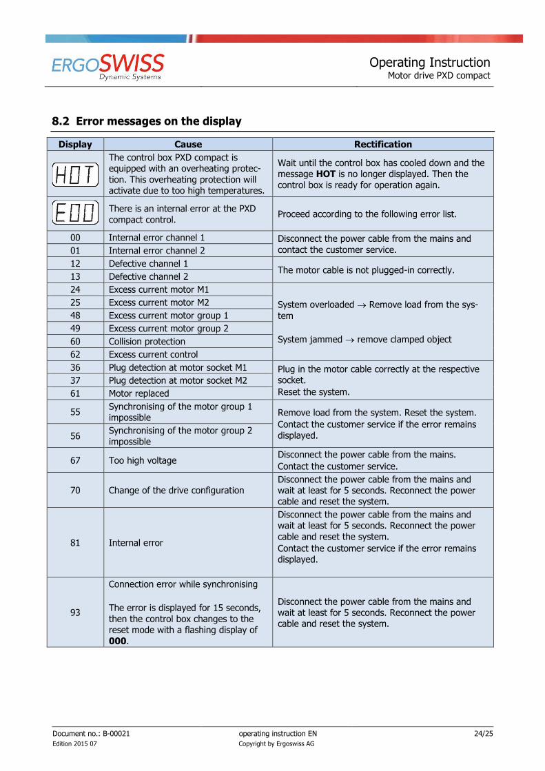
8.2 Error messages on the display
Display Cause Rectification
The control box PXD compact is equipped with an overheating protec-
tion. This overheating protection will activate due to too high temperatures.
Wait until the control box has cooled down and the message HOT is no longer displayed. Then the
control box is ready for operation again.
There is an internal error at the PXD
compact control. Proceed according to the following error list.
00 Internal error channel 1 Disconnect the power cable from the mains and
contact the customer service. 01 Internal error channel 2
12 Defective channel 1 The motor cable is not plugged-in correctly.
13 Defective channel 2
24 Excess current motor M1
System overloaded Remove load from the sys-
tem
System jammed remove clamped object
25 Excess current motor M2
48 Excess current motor group 1
49 Excess current motor group 2
60 Collision protection
62 Excess current control
36 Plug detection at motor socket M1 Plug in the motor cable correctly at the respective socket.
Reset the system.
37 Plug detection at motor socket M2
61 Motor replaced
55 Synchronising of the motor group 1 impossible
Remove load from the system. Reset the system.
Contact the customer service if the error remains
displayed. 56 Synchronising of the motor group 2
impossible
67 Too high voltage Disconnect the power cable from the mains.
Contact the customer service.
70 Change of the drive configuration Disconnect the power cable from the mains and wait at least for 5 seconds. Reconnect the power cable and reset the system.
81 Internal error
Disconnect the power cable from the mains and wait at least for 5 seconds. Reconnect the power
cable and reset the system.
Contact the customer service if the error remains displayed.
93
Connection error while synchronising
The error is displayed for 15 seconds,
then the control box changes to the reset mode with a flashing display of
000.
Disconnect the power cable from the mains and wait at least for 5 seconds. Reconnect the power cable and reset the system.

Operating Instruction Motor drive PXD compact
Document no.: B-00021
Edition 2015 07
operating instruction EN
Copyright by Ergoswiss AG
25/25
8.3 Click codes
As soon as the motor drive PXD compact is supplied with current the control utilises the integrated relays to
acoustically indicate the system state as well as the reason of the last shut down to the user.
Number of clicks Status information
2x Normal operation:
The system works flawlessly.
1x
Emergency operation:
The system is in emergency mode; the motors cannot be operated. There is an error code to be checked on the display.
3x – 6x Last shut down incomplete / forced reset:
There is an error code to be checked on the display.
8.4 Trouble-shooting
Error Cause Rectification
Drive does not work
Control box not connected Connect power cable
Motor not connected Connect motor cable
Motor defective Contact the customer service
Control box defective Contact the customer service
Manual control switch defective Replace the manual control switch
Bad connector contact Plug in all plugs correctly
Drive only move to one direction Control box defective Contact the customer service
Manual control switch defective Replace the manual control switch
Drive only moves downwards System overload Remove weight from the system
8.5 Repairs and spare parts
Repairs must only be conducted by specialists. Only original replacement parts may be used. For all repair work the system must always be unloaded and voltage-free.
ATTENTION
In no case may the control box be opened! There is the risk of an electrical shock.
8.6 Disassembly and disposal
When decommissioning and disposing of the motor drive PXD compact the electronic parts must be disposed
of separately. The system consists of components that can be fully recycled and thus they are quite safe from an environmental protection perspective. The electronic parts comply with the RoHs directive.