
VESTIL MANUFACTURING CORP MANUAL.pdf · 2020. 7. 30. · of 13 / / 16 / / / / / / ...

Rev. 6/12/2018 DJG-100, MANUAL
Copyright 2017 Vestil Manufacturing Corp. Page 1 of 15
Instruction Manual DJG-100 and DJG-100-10
Receiving instructions: After delivery, remove the packaging from the product. Inspect the product closely to determine whether it sustained damage during transport. If damage is discovered, record a complete description of it on the bill of lading. If the product is undamaged, discard the packaging.
NOTE: The end-user is solely responsible for confirming that product design, installation, use, and maintenance comply with laws, regulations, codes, and mandatory standards applied where the product is used.
Replacement Parts and Technical Assistance: To order replacement parts, labels, and accessories, contact the technical service and parts department online at http://www.vestilmfg.com/parts_info.htm. Alternatively, you may request replacement parts and/or service by calling (260) 665-7586 and asking for the Parts Department.
Vestil Manufacturing Corp. 2999 North Wayne Street, P.O. Box 507, Angola, IN 46703 Telephone: (260) 665-7586 -or- Toll Free (800) 348-0868
Fax: (260) 665-1339 www.vestilmfg.com e-mail: [email protected]
Table of Contents Signal Words………………………………………………………….……………………………………………… 2 Hazards of Improper Use……..…………………………………………………………..……………………….. 2 Exploded Parts Diagrams and Bills of Materials………..………………………………………………..…..... 3-5 115V, 1-Phase Electrical Layout Diagram and Circuit Diagram…..…………………………………………. 6-7 208-230V, 1-Phase Electrical Layout Diagram and Circuit Diagram………..………………………………. 8-9 460V, 3-Phase Electrical Layout Diagram and Circuit Diagram…………..………………………………. 10-11 Installation……………………………………………………………………………………………………….. 12-13 Operating the Barricade…………………………………………………………………………………………… 13 Inspections and Maintenance…………………………………………………………………………………….. 14 Labeling Diagram …………...………...……………………………………………………….................... ……. 14 Limited Warranty…………………………………………………………………………………………………… 15

Rev. 6/12/2018 DJG-100, MANUAL
Copyright 2017 Vestil Manufacturing Corp. Page 2 of 15
Signal Words This manual uses SIGNAL WORDS to direct the reader’s attention to statements about uses of the
product that could result in personal injury or property damage. Each signal word connotes a specific hazard level. The following are definitions of signal words that might appear in this manual.
Identifies a hazardous situation which, if not avoided, WILL result in DEATH or SERIOUS INJURY. Use of this signal word is limited to the most extreme situations.
Identifies a hazardous situation which, if not avoided, COULD result in DEATH or SERIOUS INJURY.
Indicates a hazardous situation which, if not avoided, COULD result in MINOR or MODERATE injury.
Identifies practices likely to result in product/property damage, such as operation that might damage the product.
Hazards of Improper Use:
Improper or careless use might result in serious personal injury. Read and understand the entire manual before assembling, installing, using or servicing this product. DO NOT attempt to resolve any problem(s) with the product unless you are both authorized to do so and certain that it will be safe to use afterwards. Anchor the barrier system to an intact, concrete surface with 3/4” anchor bolts of appropriate length (selected by your building engineer). DO NOT modify the product in any way without first obtaining written approval from Vestil. Unapproved modifications automatically void the Limited Warranty (p. 15) and might make the product unsafe to use. This barricade should only be used to direct vehicular traffic. It is not a guardrail. Do not apply any weight to the barricade arm, particularly as the barricade is opened. Do not hold onto the arm while it rises. Inspect the product as recommended in the “Inspections and Maintenance” section on p. 14. Do not use the product unless it is in normal condition. DO NOT use this barricade UNLESS all labels are present, easily readable (not significantly faded), and undamaged. (See “Labeling Diagram” on p. 14).
Proper maintenance is essential for this product to remain in normal, working condition. o Periodically lubricate pivot points. o Do not use brake fluid or jack oils in the hydraulic system. If oil is needed, use an anti-wear hydraulic oil with a viscosity grade of 150 SUS at 100°F, (ISO 32 cSt @ 40°C), or Dexron transmission fluid.

Rev. 6/12/2018 DJG-100, MANUAL
Copyright 2017 Vestil Manufacturing Corp. Page 3 of 15
Item Part no. Description Qty. Item Part no. Description Qty.
1 23-514-062 Frame, weldment, base tube 1 16 37021 Nylon insert lock nut, gr. 2, z-finish, 5/16”-18
1
2 23-514-061 Frame, weldment, arm rest 1 17 11213 Bolt, HHCS, #2, z-plated, 1/2”-13x21/2”
1
3 23-514-063 Weldment, arm 1 18 33012 Flat washer, low carbon, z-finish, 1/2”
1
4 23-537-001 Weldment, arm lock 1 19 37030 1/2”-13 Nylon insert lock nut 1 5 99-027-003 Pulley, cable 5 20 11103 Hex bolt, gr. A, z-plated, 3/8”-16x3/4” 3 6 21-042-002-001 Hand winch, foldable handle grip 1 21 21-112-003 Pin, 1/2”x115/16” retaining clevis 4 7 23-112-004 Pin, arm stop 1 22 65080 Ext. prong cotter pin, z-finish,1/8”x2” 4 8 33011 Flat washer, USS, plain, 1/2” 8 23 11215 Hex bolt, gr. A, z-finish, 1/2”-13x3” 1 9 23-524-103 Weldment, guard, shroud 1 24 23-024-343 Guard, winch, formed 1
10 23-048-001 Bumper, arm stop 1 25 11003 Hex bolt, gr. A, z-plated, 1/4”-20x3/4” 2 11 11111 Bolt, gr. A, zinc plated, 3/8”-16x2” 2 26 36109 Hex nut, gr. A, plain, 1/2”-13 1
12 33008 Flat washer, low carbon, USS, z-plated, 3/8”
5 27 32416 Thread cutting screw, slotted, type F, z-plated, 5/16”-18x3/4”
4
13 36106 Hex nut, gr. A, z-plated, 3/8”-16 2 28 33618 Medium split lock washer, 1/4” 2 14 23-024-154 Guard, tube 2 29 99-051-022 Black & yellow safety tape, 118” 2
15 11063 Hex bolt, gr. A, z-finish, 5/16”-18 x 21/2”
1 30 23-537-020 Weldment, lock bar 1
DJG-100MW Exploded Parts Diagram and Bill of Materials

Rev. 6/12/2018 DJG-100, MANUAL
Copyright 2017 Vestil Manufacturing Corp. Page 4 of 15
Item Part no. Description Qty. Item Part no. Description Qty.
1 23-514-020 Frame, weldment 1 16 11055 Hex bolt, grade A, zinc plated, 5/16”-18x1”
4
2 23-514-019 Frame, weldment, safety bar 1 17 36104 Hex nut, grade A, zinc plated, 5/16”-18
4
3 23-112-003 Pin, hinge 1 18 23-529-001 Control box enclosure 1
4 33454 Narrow machinery bushing, plain, 13/4” x 18ga.
4 19 23-137-001 Motor, manifold, reservoir assy. 1
5 68021 External retaining ring, phosphate finish, 11/8”
4 20 29-001-017-001 Bumper 1
6 23-024-095 Guard/cover, plate 1 21 11114 Bolt, HHCS, 3/8”-16x23/4” 2
7 32416 Thread cutting screw, slotted, type F, zinc plated, 5/16”-18x3/4”
1 22 23-112-002 Pin, hinge 1
8 01-118-001 Bolt, cylinder retaining 1 23 99-051-021 Black & yellow safety tape. 114” 2 9 23-514-018 Weldment, arm rest 1 24 01-020-006 Boss, EHLT double cylinder 2
10 41125 Rivet, SB64, 3/16” x 0.250” 9 25 99-021-903-001 Cylinder, hydraulic, 2” x 10” 1 11 23-015-001 Guard, extrusion, rubber 1 26 23-537-020 Weldment, lock bar 1 12 33010 Washer, flat 2 **27 23-034-002 Photo eye, transmitter-receiver 1
13 37024 Nylon insert lock nut, grade 2, zinc finish, 3/8”-16
2 **28 23-034-003 Control box, interface multiplexer 1
14 11003 Hex bolt, grade A, zinc plated, 1/4”-20x3/4”
2 29 23-034-001 Guard, extrusion, aluminum 2
15 36102 Hex nut, grade A, zinc plated, 1/4”-20
2 30 23-034-004 Guard, extrusion, aluminum 1
DJG-100 Exploded Parts Diagram and Bill of Materials
** = Not shown in diagram

Rev. 6/12/2018 DJG-100, MANUAL
Copyright 2017 Vestil Manufacturing Corp. Page 5 of 15
Item Part no. Description Qty. Item Part no. Description Qty.
1 23-514-020 Frame, weldment 1 16 11055 Hex bolt, grade A, zinc plated, 5/16”-18x1”
4
2 23-514-096 Frame, weldment, safety bar 1 17 36104 Hex nut, grade A, zinc plated, 5/16”-18
4
3 23-112-003 Pin, hinge 1 18 23-529-001 Control box enclosure 1
4 33454 Narrow machinery bushing, plain, 13/4” x 18ga.
4 19 23-137-001 Motor, manifold, reservoir assy.
1
5 68021 External retaining ring, phosphate finish, 11/8”
4 20 29-001-017-
001 Bumper 1
6 23-024-095 Guard/cover, plate 1 21 11114 Bolt, HHCS, 3/8”-16x23/4” 2
7 32416 Thread cutting screw, slotted, type F, zinc plated, 5/16”-18x3/4”
1 22 23-112-002 Pin, hinge 1
8 01-118-001 Bolt, cylinder retaining 1 23 99-051-023 Black & yellow safety tape. 114”
2
9 23-514-018 Weldment, arm rest 1 24 01-020-006 Boss, EHLT double cylinder 2 10 41125 Rivet, SB64, 3/16” x 0.250” 9 **25 23-034-002 Photo eye, transmitter-receiver 1
11 23-015-004 Guard, extrusion, rubber 1 **26 23-034-003 Control box, interface multiplexer
1
12 33010 Washer, flat 2 27 99-021-903-
001 Cylinder, hydraulic, 2” x 10” 1
13 37024 Nylon insert lock nut, grade 2, zinc finish, 3/8”-16
2 28 23-537-020 Weldment, lock bar 1
14 11003 Hex bolt, grade A, zinc plated, 1/4”-20x3/4”
2 29 23-034-001 Guard, extrusion, aluminum 2
15 36102 Hex nut, grade A, zinc plated, 1/4”-20
2 30 23-034-005 Guard, extrusion, aluminum 1
DJG-100-10 Exploded Parts Diagram and Bill of Materials
** = Not shown in diagram

Rev. 6/12/2018 DJG-100, MANUAL
Copyright 2017 Vestil Manufacturing Corp. Page 6 of 15
Electrical Layout: 115V, 1-Phase with Sensor (23-124-001 Rev. H)
Rev. 6/12/2018 DJG-100, MANUAL
Copyright 2017 Vestil Manufacturing Corp. Page 7 of 15
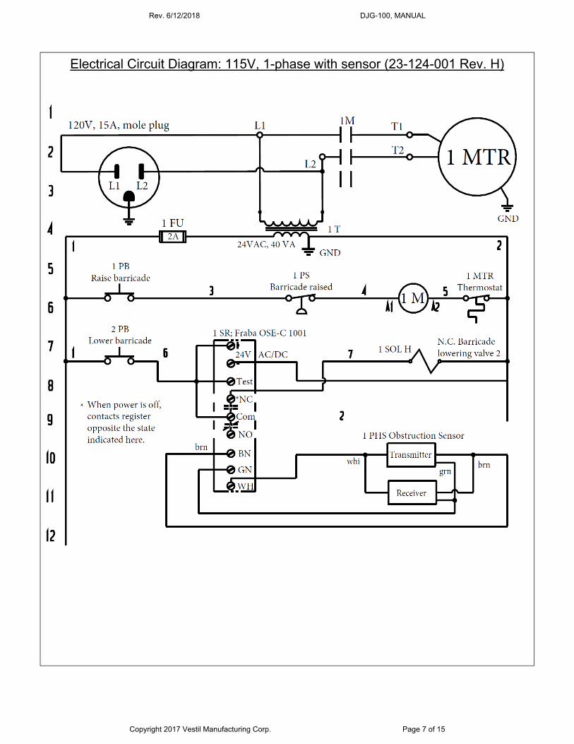
Electrical Circuit Diagram: 115V, 1-phase with sensor (23-124-001 Rev. H)
Rev. 6/12/2018 DJG-100, MANUAL
Copyright 2017 Vestil Manufacturing Corp. Page 8 of 15
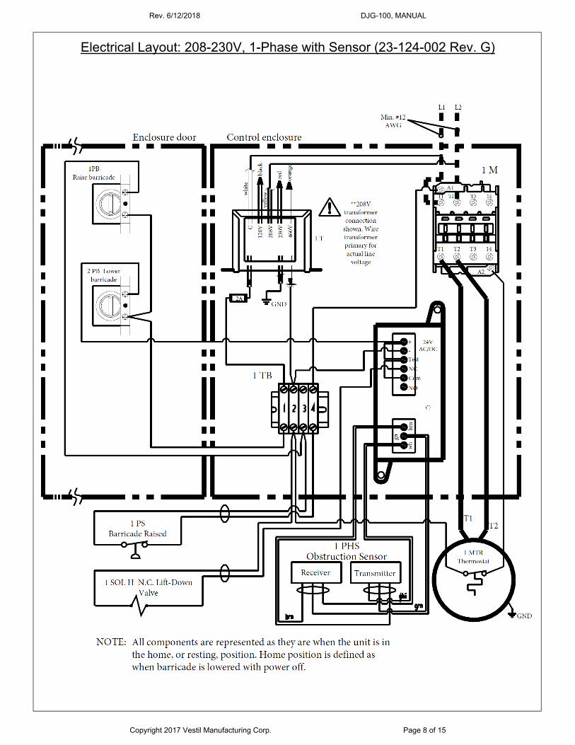
Electrical Layout: 208-230V, 1-Phase with Sensor (23-124-002 Rev. G)
Rev. 6/12/2018 DJG-100, MANUAL
Copyright 2017 Vestil Manufacturing Corp. Page 9 of 15
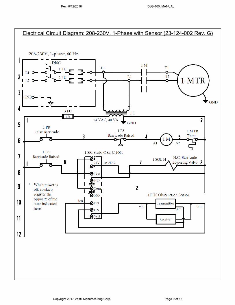
Electrical Circuit Diagram: 208-230V, 1-Phase with Sensor (23-124-002 Rev. G)

Rev. 6/12/2018 DJG-100, MANUAL
Copyright 2017 Vestil Manufacturing Corp. Page 10 of 15
Electrical Layout: 460V, 3-Phase with Sensor (23-124-003 Rev. G)
Rev. 6/12/2018 DJG-100, MANUAL
Copyright 2017 Vestil Manufacturing Corp. Page 11 of 15
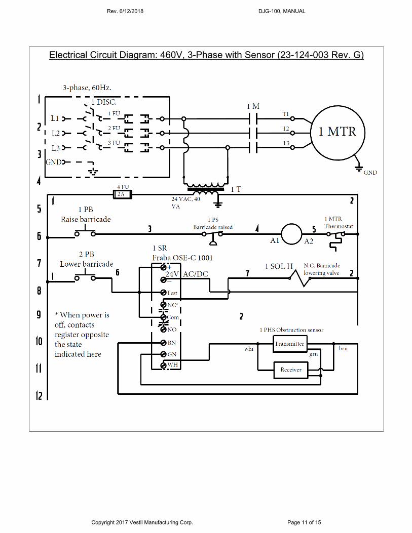
Electrical Circuit Diagram: 460V, 3-Phase with Sensor (23-124-003 Rev. G)
Rev. 6/12/2018 DJG-100, MANUAL
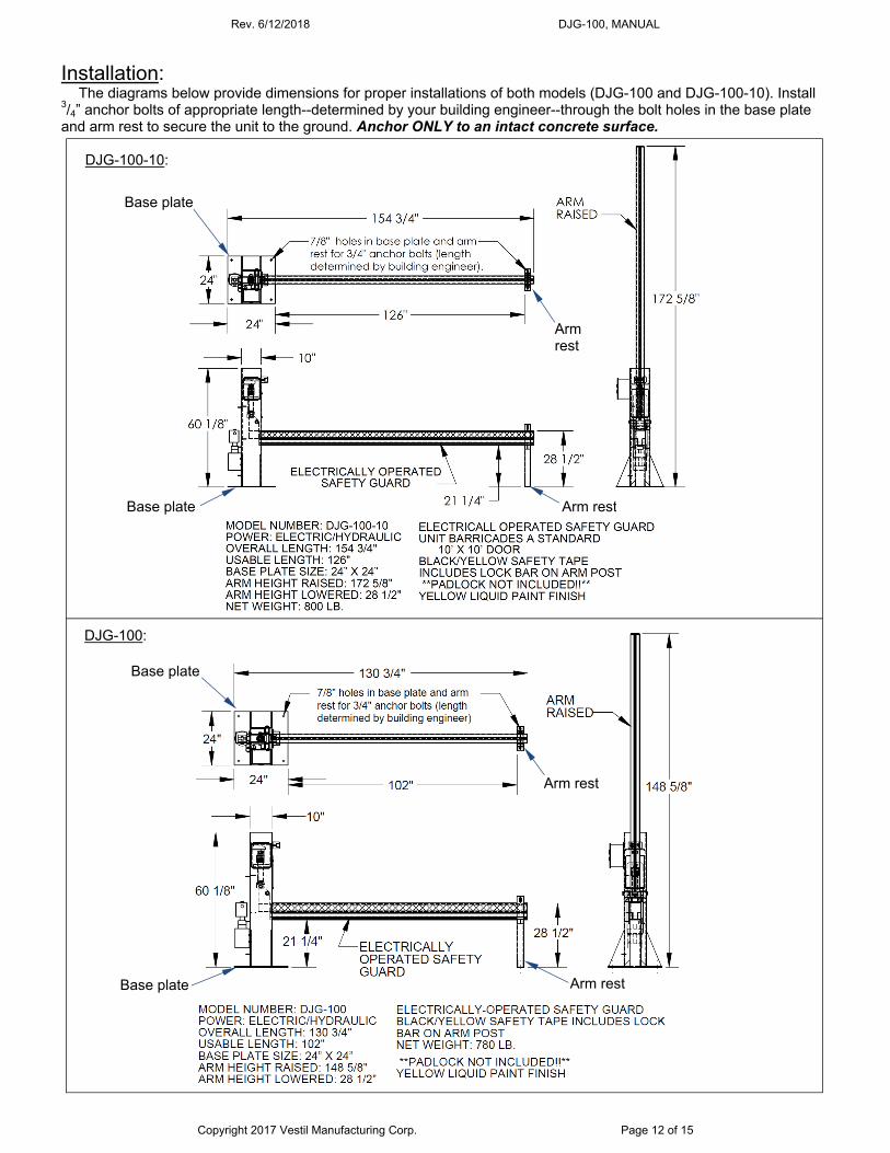
Copyright 2017 Vestil Manufacturing Corp. Page 12 of 15
Installation: The diagrams below provide dimensions for proper installations of both models (DJG-100 and DJG-100-10). Install
3/4” anchor bolts of appropriate length--determined by your building engineer--through the bolt holes in the base plate and arm rest to secure the unit to the ground. Anchor ONLY to an intact concrete surface.
Base plate
Base plate
Arm rest
Arm rest
Base plate
Base plate
Arm rest
Arm rest
DJG-100-10:
DJG-100:

Rev. 6/12/2018 DJG-100, MANUAL
Copyright 2017 Vestil Manufacturing Corp. Page 13 of 15
Operating the barricade (electric-hydraulic models): To raise the barricade arm, press the upper button on the control box. Press the lower button to lower the arm. The arm only moves as long as a button is pressed. The arm stops moving when the operator releases either button. The barricade arm is equipped with an obstruction sensing switch that halts arm movement while the lower control button is pressed. The switch is mounted to the underside of the arm. If the arm contacts an obstruction while lowering, a vehicle for example, the switch is activated and the arm stops moving. Press the upper button to raise the arm and remove the obstruction before lowering the arm again. The arm can be locked in the lowered configuration by inserting the locking bar through the slots in the arm rest. Do not try to raise the arm with the lock bar installed.
(Arm) Lock bar
Control box
Upper button (raises arm)
Lower button (lowers arm)
Obstruction sensor
Arm
Arm rest
Main frame
DJG-100MW:
Arm rest
Arm rest
Base plate
Base plate
7/8” holes in base plate and arm rest for 3/4” anchor bolts (length determined by your building engineer). Anchor ONLY to intact concrete surface.
Operation: To raise the arm, simply turn the winch handle clockwise. As the right-most diagram above indicates, the arm is not vertical when fully raised. Do not keep turning the handle in an attempt to further raise the arm. To lower the arm, turn the handle counterclockwise.
Arm is not vertical when fully raised. The barricade could be damaged if you continue turning the handle.

Rev. 6/12/2018 DJG-100, MANUAL
Copyright 2017 Vestil Manufacturing Corp. Page 14 of 15
Inspections and Maintenance: After installing the unit but before using it for the first time, create a written record that describes the appearance of each major component, including the main frame, arm mechanism, arm rest, pins, electrical control box, obstruction sensor, and anchor bolts. Raise and lower the arm. Record your observations about how the unit looks and sounds as the arm raises and lowers. This written record establishes “normal condition”. When conducting future inspections compare those observations with the written record to determine whether a component is in normal condition or requires repair or replacement.
Regular inspections and maintenance are necessary for the barricade to remain in normal condition. At least once per month, inspect the following components:
1. Obstruction sensor (mounted to underside of arm): Raise the arm about 1 foot about the arm rest. Press against the sensor (with a broom handle, for instance). While pressing the sensor, press the lower button on the control box. Confirm that the arm does not lower when the button is pressed. If the arm still lowers, then the sensor is malfunctioning and must be repaired.
2. Labels: all labels should be readable and located as shown in the “Labeling Diagram” (below). Contact Vestil to order a replacement for any label that is not easily readable (e.g. faded or damaged) or missing.
3. Hardware: Bolts, nuts, washers, pins, hitch pins; Anchor bolts: Confirm that all anchor bolts are solidly attached to the ground. The barricade and arm rest
should not be able to wobble. 4. Main frame and arm rest: confirm that both are square, rigid, and not severely damaged, i.e. not rusted, bent,
cracked, etc. Examine all welds. 5. Electrical control box, pushbuttons, and hydraulic system: examine the box and buttons for damage. Cycle the
arm all the way and all the way down. The arm should move smoothly in both directions.
Labeling diagram:
A
C
B
D
E
F
F
A
B: Label 221
C: Label 248-251 (matched to line voltage)
A: Label 208
D: Label 287
E: Label 206
F: Label 204
G
G: Label 268

Rev. 6/12/2018 DJG-100, MANUAL
Copyright 2017 Vestil Manufacturing Corp. Page 15 of 15
LIMITED WARRANTY
Vestil Manufacturing Corporation (“Vestil”) warrants this product to be free of defects in material and workmanship during the warranty period. Our warranty obligation is to provide a replacement for a defective, original part covered by the warranty after we receive a proper request from the Warrantee (you) for warranty service.
Who may request service? Only a warrantee may request service. You are a warrantee if you purchased the product from Vestil or from an
authorized distributor AND Vestil has been fully paid.
Definition of “original part”? An original part is a part used to make the product as shipped to the Warrantee.
What is a “proper request”? A request for warranty service is proper if Vestil receives: 1) a photocopy of the Customer Invoice that displays the
shipping date; AND 2) a written request for warranty service including your name and phone number. Send requests by one of the following methods: US Mail Fax Email Vestil Manufacturing Corporation (260) 665-1339 [email protected] 2999 North Wayne Street, PO Box 507 Phone Enter “Warranty service request” Angola, IN 46703 (260) 665-7586 in subject field.
In the written request, list the parts believed to be defective and include the address where replacements should be delivered. After Vestil receives your request for warranty service, an authorized representative will contact you to determine whether your claim is covered by the warranty. Before providing warranty service, Vestil will require you to send the entire product, or just the defective part (or parts), to its facility in Angola, IN.
What is covered under the warranty? The warranty covers defects in the following original, dynamic parts: motors, hydraulic pumps, motor controllers, and
cylinders. It also covers defects in original parts that wear under normal usage conditions (“wearing parts”), such as bearings, hoses, wheels, seals, brushes, and batteries.
How long is the warranty period? The warranty period for original dynamic components is 90 days. For wearing parts, the warranty period is 90 days.
Both warranty periods begin on the date Vestil ships the product to the Warrantee. If the product was purchased from an authorized distributor, the periods begin when the distributor ships the product. Vestil may, at its sole discretion, extend a warranty period for products shipped from authorized distributors by up to 30 days to account for shipping time.
If a defective part is covered by the warranty, what will Vestil do to correct the problem? Vestil will provide an appropriate replacement for any covered part. An authorized representative of Vestil will contact
you to discuss your claim.
What is not covered by the warranty? The Warrantee (you) are responsible for paying labor costs and freight costs to return the product to Vestil for warranty
service.
Events that automatically void this Limited Warranty. Misuse; Negligent assembly, installation, operation or repair; Installation/use in corrosive environments; Inadequate or improper maintenance; Damage sustained during shipping; Collisions or other accidents that damage the product; Unauthorized modifications: Do not modify the product IN ANY WAY without first receiving written authorization from
Vestil.
Do any other warranties apply to the product? Vestil Manufacturing Corp. makes no other express warranties. All implied warranties are disclaimed to the extent
allowed by law. Any implied warranty not disclaimed is limited in scope to the terms of this Limited Warranty. Vestil makes no warranty or representation that this product complies with any state or local design, performance, or safety code or standard. Noncompliance with any such code or standard is not a defect in material or workmanship.


![J#(+ J#)& J6h ndj ldjaY ZmeZXi [gdb ! ^i ^h djg V^b id egdk^YZ djg kVajZY XjhidbZgh l^i] i]Z WZhi ^c V[iZg hVaZh VcY hZgk^XZ# Id iV`Z VYkVciV\Z d[ Vcn ZmiZcYZY lVggVcin d[[ZgZY! Vaa](https://static.fdocuments.in/doc/165x107/60de7488a984846d0a470a5a/j-j-j-6h-ndj-ldjay-zmezxi-gdb-i-h-djg-vb-id-egdkyz-djg-kvajzy-xjhidbzgh.jpg)


