VESTIL MANUFACTURING CORP - Grainger Industrial Supply · 2015-05-20 · 1 19 15-024-085 End cap 2...
14
Rev. 5/7/2014 CBFC, manual.doc Copyright 2014 Vestil Manufacturing Co. Page 1 of 14 CBFC COUNTERBALANCED FLOOR CRANE USE AND MAINTENANCE MANUAL Receiving instructions: After delivery, IMMEDIATELY remove the packaging from the product in a manner that preserves the packaging and maintains the orientation of the product in the packaging; then inspect the product closely to determine whether it sustained damage during transport. If damage is discovered during the inspection, immediately record a complete description of the damage on the bill of lading. If the product is undamaged, discard the packaging. NOTES: 1) Compliance with laws, regulations, codes, and non-voluntary standards enforced in the location where the product is used is exclusively the responsibility of the owner/end-user 2) VESTIL is not liable for any injury or property damage that occurs as a consequence of failing to apply either: a) Instructions in this manual; or b) information provided on labels affixed to the product. Neither is Vestil responsible for any consequential damages sustained as a result of failing to exercise sound judgment while assembling, installing, using or maintaining this product. VESTIL MANUFACTURING CORP. 2999 North Wayne Street, P.O. Box 507, Angola, IN 46703 Telephone: (260) 665-7586 -or- Toll Free (800) 348-0868 Fax: (260) 665-1339 www.vestilmfg.com e-mail: [email protected] Table of Contents Product Specifications…………………………………..…………………………………………………………………….. 2 Hazard Identification: Explanation of Signal Words….……………………………………………………………………. 2 Safety Recommendations………………………………………………………………..…………………………………… 3 FIG. 1A: CBFC-500 exploded parts diagram & bill of materials………………………………………………………….. 4 FIG. 1B: CBFC-500 rated loads for specified boom lengths…….………………………………………………………… 5 FIG. 2A: CBFC-1000 exploded parts diagram & bill of materials…….…………………………………………………… 6 FIG. 2B: CBFC-1000 rated loads for specified boom lengths…..……………………………………………................... 7 FIG. 3A: CBFC-2000 exploded parts diagram & bill of materials…………..……………………………………............. 8 FIG. 3B: CBFC-2000 rated loads for specified boom lengths…………………………………………………………….. 9 FIG. 4: Manual hydraulic pump exploded parts diagram & bill of materials…………………………………………….. 10 Operation instructions………………………………………………………………………………………………………….. 11 Manually operated hydraulic pump…………………………………………………………………………………………… 11 Inspections…………………………………………………………………………………………………..............................12 Maintenance……….…………………………………………………………………………………………………………… 13 Label Placement Diagram……...…………………………………………………………………………………………….. 13 Limited Warranty…...………………………………………………………………………………………………………….. 14
Transcript of VESTIL MANUFACTURING CORP - Grainger Industrial Supply · 2015-05-20 · 1 19 15-024-085 End cap 2...

Rev. 5/7/2014 CBFC, manual.doc
Copyright 2014 Vestil Manufacturing Co. Page 1 of 14
CBFC COUNTERBALANCED FLOOR CRANE USE AND MAINTENANCE MANUAL
Receiving instructions:
After delivery, IMMEDIATELY remove the packaging from the product in a manner that preserves the packaging and maintains the orientation of the product in the packaging; then inspect the product closely to determine whether it sustained damage during transport. If damage is discovered during the inspection, immediately record a complete description of the damage on the bill of lading. If the product is undamaged, discard the packaging. NOTES: 1) Compliance with laws, regulations, codes, and non-voluntary standards enforced in the location where the product is used is exclusively the responsibility of the owner/end-user 2) VESTIL is not liable for any injury or property damage that occurs as a consequence of failing to apply either: a) Instructions in this manual; or b) information provided on labels affixed to the product. Neither is Vestil responsible for any consequential damages sustained as a result of failing to exercise sound judgment while assembling, installing, using or maintaining this product.
VESTIL MANUFACTURING CORP. 2999 North Wayne Street, P.O. Box 507, Angola, IN 46703 Telephone: (260) 665-7586 -or- Toll Free (800) 348-0868
Fax: (260) 665-1339 www.vestilmfg.com e-mail: [email protected]
Table of Contents Product Specifications…………………………………..…………………………………………………………………….. 2 Hazard Identification: Explanation of Signal Words….……………………………………………………………………. 2 Safety Recommendations………………………………………………………………..…………………………………… 3 FIG. 1A: CBFC-500 exploded parts diagram & bill of materials………………………………………………………….. 4 FIG. 1B: CBFC-500 rated loads for specified boom lengths…….………………………………………………………… 5 FIG. 2A: CBFC-1000 exploded parts diagram & bill of materials…….…………………………………………………… 6 FIG. 2B: CBFC-1000 rated loads for specified boom lengths…..……………………………………………................... 7 FIG. 3A: CBFC-2000 exploded parts diagram & bill of materials…………..……………………………………............. 8 FIG. 3B: CBFC-2000 rated loads for specified boom lengths…………………………………………………………….. 9 FIG. 4: Manual hydraulic pump exploded parts diagram & bill of materials…………………………………………….. 10 Operation instructions………………………………………………………………………………………………………….. 11 Manually operated hydraulic pump…………………………………………………………………………………………… 11 Inspections………………………………………………………………………………………………….............................. 12 Maintenance……….…………………………………………………………………………………………………………… 13 Label Placement Diagram……...…………………………………………………………………………………………….. 13 Limited Warranty…...………………………………………………………………………………………………………….. 14

Rev. 5/7/2014 CBFC, manual.doc
Copyright 2014 Vestil Manufacturing Co. Page 2 of 14
Product specifications: Dimensions and other product specifications appear in the following table:
Model Front (load) caster type
Rear caster type Net weight
CBFC-500 8in. rigid 6in. swivel 1,089 lb. (495kg)
CBFC-1000 8in. rigid 6in. swivel 1,508 lb. (685.5kg)
CBFC-2000 8in. rigid 6in. swivel 2,610 lb.
(1,186.4kg)
Hazard Identification--Explanation of SIGNAL WORDS
This manual uses SIGNAL WORDS to indicate the likelihood of personal injuries, as well as the probable seriousness of those injuries, if the product is misused in the ways described. Other signal words call attention to uses of the product likely cause property damage. The signal words used appear below along with the meaning of each word:
Identifies a hazardous situation which, if not avoided, WILL result in DEATH or SERIOUS INJURY. Use of this signal word is limited to the most extreme situations.
Identifies a hazardous situation which, if not avoided, COULD result in DEATH or SERIOUS INJURY.
Indicates a hazardous situation which, if not avoided, COULD result in MINOR or MODERATE injury.
Identifies practices likely to result in product/property damage, such as operation that might damage the product.
Each person who assembles, installs, uses, or maintains this product should read the entire manual in advance and fully understand the directions. If after reading the manual you do not understand an instruction, ask your supervisor or employer for clarification, because failure to adhere to the directions in this manual might result in serious personal injury.
Rev. 5/7/2014 CBFC, manual.doc
Copyright 2014 Vestil Manufacturing Co. Page 3 of 14
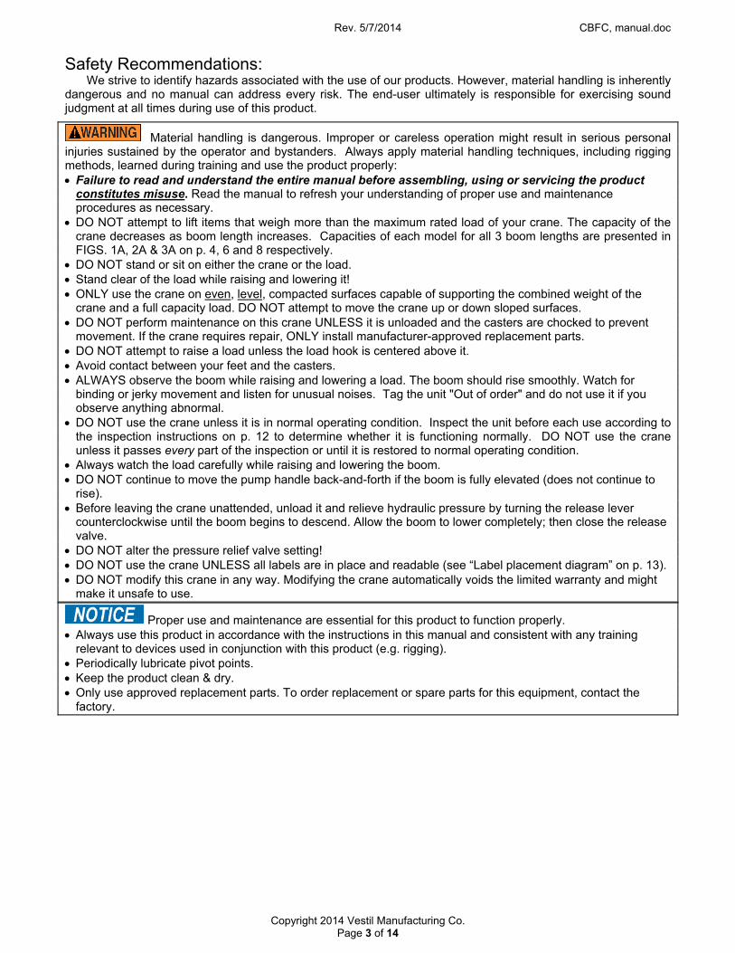
Safety Recommendations: We strive to identify hazards associated with the use of our products. However, material handling is inherently
dangerous and no manual can address every risk. The end-user ultimately is responsible for exercising sound judgment at all times during use of this product.
Material handling is dangerous. Improper or careless operation might result in serious personal injuries sustained by the operator and bystanders. Always apply material handling techniques, including rigging methods, learned during training and use the product properly: Failure to read and understand the entire manual before assembling, using or servicing the product
constitutes misuse. Read the manual to refresh your understanding of proper use and maintenance procedures as necessary.
DO NOT attempt to lift items that weigh more than the maximum rated load of your crane. The capacity of the crane decreases as boom length increases. Capacities of each model for all 3 boom lengths are presented in FIGS. 1A, 2A & 3A on p. 4, 6 and 8 respectively.
DO NOT stand or sit on either the crane or the load. Stand clear of the load while raising and lowering it! ONLY use the crane on even, level, compacted surfaces capable of supporting the combined weight of the
crane and a full capacity load. DO NOT attempt to move the crane up or down sloped surfaces. DO NOT perform maintenance on this crane UNLESS it is unloaded and the casters are chocked to prevent
movement. If the crane requires repair, ONLY install manufacturer-approved replacement parts. DO NOT attempt to raise a load unless the load hook is centered above it. Avoid contact between your feet and the casters. ALWAYS observe the boom while raising and lowering a load. The boom should rise smoothly. Watch for
binding or jerky movement and listen for unusual noises. Tag the unit "Out of order" and do not use it if you observe anything abnormal.
DO NOT use the crane unless it is in normal operating condition. Inspect the unit before each use according to the inspection instructions on p. 12 to determine whether it is functioning normally. DO NOT use the crane unless it passes every part of the inspection or until it is restored to normal operating condition.
Always watch the load carefully while raising and lowering the boom. DO NOT continue to move the pump handle back-and-forth if the boom is fully elevated (does not continue to
rise). Before leaving the crane unattended, unload it and relieve hydraulic pressure by turning the release lever
counterclockwise until the boom begins to descend. Allow the boom to lower completely; then close the release valve.
DO NOT alter the pressure relief valve setting! DO NOT use the crane UNLESS all labels are in place and readable (see “Label placement diagram” on p. 13). DO NOT modify this crane in any way. Modifying the crane automatically voids the limited warranty and might
make it unsafe to use.
Proper use and maintenance are essential for this product to function properly. Always use this product in accordance with the instructions in this manual and consistent with any training
relevant to devices used in conjunction with this product (e.g. rigging). Periodically lubricate pivot points. Keep the product clean & dry. Only use approved replacement parts. To order replacement or spare parts for this equipment, contact the
factory.

Rev. 5/7/2014 CBFC, manual.doc
Copyright 2014 Vestil Manufacturing Co. Page 4 of 14
FIG. 1A: CBFC-500 Exploded Parts Diagram & Bill of Materials
Item no. Part no. Description Quantity
Item no. Part no. Description Quantity
1 28-514-089 Frame, inner boom weldment 1 14 16-132-
216 Load caster 2
2 08-145-003 Specialty hardware, 2-ton shackle
1 15 15-525-
007 Handle, weldment 1
3 08-145-001 Load hook, 2-ton capacity 1 16 11209 1/2in. – 13 x 11/2in. HHCS #2 zinc-plated bolt
2
4 28-612-001 Pin, weldment, pivot, outer boom
1 17 37030 1/2in. – 13 nylock insert lock nut 2
5 65077 1/8in. x 11/4in. cotter pin zinc-plated
3 18 37032 1/2in. nylock insert jam nut 2
6 28-514-088 Frame, weldment, outer boom
1 19 15-024-
085 End cap 2
7 99-112-004 Pin, self-locking quick release, general
1 20 09-021-
004 Cylinder, hydraulic displacement 1
8 36102 1/4in. – 20 hex nut zinc-plated 4 21 66172 3/4in. x 4in. clevis pin 2
9 11007 1/4in. – 20 x 11/4in. hex bolt 4 22 16-145-
031
1/2in. – 13 x 31/2in. bolt with grease zerk
2
10 99-640-003 Assembly, hand pump, 1/2 gallon tank
1 23 16-014-
389 Frame, counterweight lid 1
11 16-132-227 Caster, 8/3-FWB-NTP 2 24 16-514-
235 Weldment, CBFC-500 frame 1
12 11359 3/4in. – 10 x 3in. HHCS #2 zinc-plated
2 25 33011 1/2in. USS flat washer plain 2
13 37039 3/4in. – 10 nylock nut zinc-plated
2 26 33618 1/4in. lock washer 4

Rev. 5/7/2014 CBFC, manual.doc
Copyright 2014 Vestil Manufacturing Co. Page 5 of 14
FIG 1B: CBFC-500 rated loads for specified boom lengths
Although the outer boom has only one set of pin holes, the inner boom has 3 sets to allow boom length to be adjusted. Boom length increases in 12 inch increments. Boom length determines the maximum rated load of the crane, which decreases as boom length increases as indicated in the table below:
Boom length Maximum rated load391/4 inches 500 lb. (227.3kg) 511/4 inches 400 lb. (181.8kg) 631/4 inches 300 lb. (136.4kg)
DO NOT use the crane unless the inner and outer booms are securely pinned together.

Rev. 5/7/2014 CBFC, manual.doc
Copyright 2014 Vestil Manufacturing Co. Page 6 of 14
FIG. 2A: CBFC-1000 Exploded Parts Diagram & Bill of Materials
Item no. Part no. Description Quantity
Item no. Part no. Description Quantity
1 28-514-089 Frame, inner boom weldment 1 14 16-132-216 Load caster 2
2 08-145-003 Specialty hardware, 2-ton shackle
1 15 15-525-007 Handle, weldment 1
3 08-145-001 Load hook, 2-ton capacity 1 16 11209 1/2in. – 13 x 11/2in. HHCS #2 zinc-plated bolt
2
4 28-612-001 Pin, weldment, pivot, outer boom
1 17 37030 1/2in. – 13 nylock insert lock nut 2
5 65077 1/8in. x 11/4in. cotter pin zinc-plated
3 18 37032 1/2in. nylock insert jam nut 2
6 28-514-088 Frame, weldment, outer boom
1 19 15-024-085 End cap 2
7 99-112-004 Pin, self-locking quick release, general
1 20 09-021-004 Cylinder, hydraulic displacement 1
8 36102 1/4in. – 20 hex nut zinc-plated 4 21 66172 3/4in. x 4in. clevis pin 2
9 11007 1/4in. – 20 x 11/4in. hex bolt 4 22 16-145-031 1/2in. – 13 x 31/2in. bolt with grease zerk
2
10 99-640-003 Assembly, hand pump, 1/2 gallon tank
1 23 16-514-236 Weldment, CBFC-1000 frame 1
11 16-132-227 Caster, 8/3-FWB-NTP 2 24 16-014-389 Frame, counterweight lid 1
12 11359 3/4in. – 10 x 3in. HHCS #2 zinc-plated
2 25 33011 1/2in. USS flat washer plain 2
13 37039 3/4in. – 10 nylock nut zinc-plated
2 26 33618 1/4in. lock washer 4
Rev. 5/7/2014 CBFC, manual.doc
Copyright 2014 Vestil Manufacturing Co. Page 7 of 14
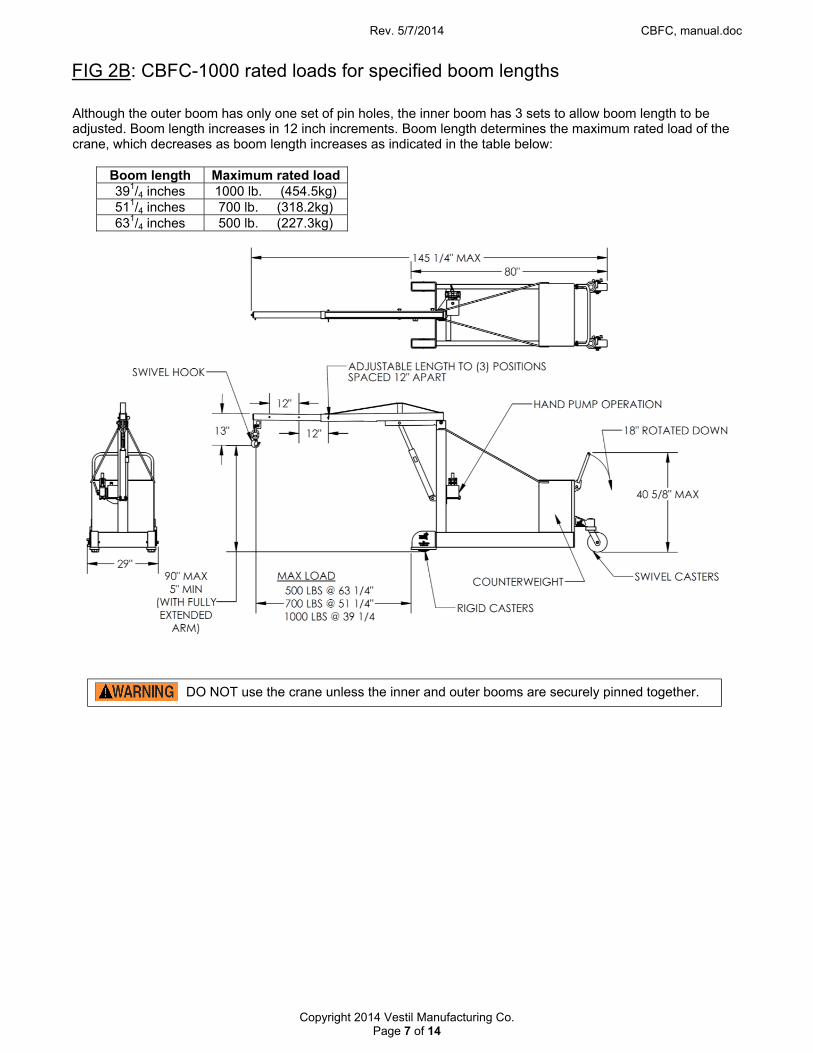
FIG 2B: CBFC-1000 rated loads for specified boom lengths
Although the outer boom has only one set of pin holes, the inner boom has 3 sets to allow boom length to be adjusted. Boom length increases in 12 inch increments. Boom length determines the maximum rated load of the crane, which decreases as boom length increases as indicated in the table below:
Boom length Maximum rated load391/4 inches 1000 lb. (454.5kg) 511/4 inches 700 lb. (318.2kg) 631/4 inches 500 lb. (227.3kg)
DO NOT use the crane unless the inner and outer booms are securely pinned together.

Rev. 5/7/2014 CBFC, manual.doc
Copyright 2014 Vestil Manufacturing Co. Page 8 of 14
FIG. 3A: CBFC-2000 Exploded Parts Diagram & Bill of Materials
Item no. Part no. Description Quantity
Item no. Part no. Description Quantity
1 28-514-089 Frame, inner boom weldment 1 14 37039 3/4in. – 10 nylock nut zinc-plated 2
2 08-145-003 Specialty hardware, 2-ton shackle
1 15 16-132-216 Caster/wheel 2
3 08-145-001 Load hook, 2-ton capacity 1 16 15-525-007 Handle, weldment 1
4 28-612-001 Pin, weldment, pivot, outer boom
1 17 11209 1/2in. – 13 x 11/2in. HHCS #2 zinc-plated
2
5 65077 1/8in. x 11/4in. cotter pin zinc-plated
1 18 37030 1/2in. – 13 nylon insert lock nut 2
6 06-112-010 Pin, linkage, FM-EOD 2 19 37032 1/2in. – 13 nylon insert jam nut 2
7 65127 3/16in. x 2in. cotter pin zinc-plated
2 20 15-024-085 End cap 2
8 99-112-004 Pin, self-locking quick release 1 21 28-514-114 Frame, weldment, outer boom 1
9 36102 1/4in. – 20 hex nut zinc-plated 4 22 99-021-928 2in. x 18in. stroke hydraulic cylinder
1
10 11007 1/4in. – 2- UNC x 11/4in. hex bolt 4 23 16-514-237 Weldment, CBFC-2000 frame 1
11 99-640-003 Assembly, hand pump 1/4 gal. tank
1 24 16-145-031 1/2in. – 13 x 31/2in. bolt with grease zerk
2
12 16-132-227 Caster, 8/3-FWB-NTP 2 25 16-014-390 Frame, counterweight lid 1
13 11359 3/4in. – 10 x 3in. HHCS #2 zinc-plated
2 26 33011 1/2in. USS flat washer plain 2
27 33618 1/4in. lock washer 4

Rev. 5/7/2014 CBFC, manual.doc
Copyright 2014 Vestil Manufacturing Co. Page 9 of 14
FIG. 3B: CBFC-2000 rated loads for specified boom lengths
Although the outer boom has only one set of pin holes, the inner boom has 3 sets to allow boom length to be adjusted. Boom length increases in 12 inch increments. Boom length determines the maximum rated load of the crane, which decreases as boom length increases as indicated in the table below:
Boom length Maximum rated load391/4 inches 2000 lb. (909.1kg) 511/4 inches 1500 lb. (681.8kg) 631/4 inches 1000 lb. (454.5kg)
OUTER BOOM
INNER BOOM
DO NOT use the crane unless the inner and outer booms are securely pinned together.

Rev. 5/7/2014 CBFC, manual.doc
Copyright 2014 Vestil Manufacturing Co. Page 10 of 14
FIG. 4: Manual Hydraulic Pump (99-640-003) Exploded Parts Diagram & Bill of Materials (models produced before June 1, 2014)
Item no. Part no. Description Quantity
Item no. Part no. Description Quantity
1 99-140-003 Hand pump assembly 1 1.16 99-016-045 Bracket, pivot, casting 1 1.1 99-039-003 Pump, manual, hand pump 1 1.17 99-144-003 Wiper, solid profile, piston 2 1.2 99-110-007 1/4in. ball bearing 2 1.18 99-113-005 Spacer, seal 2 1.3 99-146-004 Spring, compression, inlet check 2 1.19 0129169 Lock washer, high collar, zinc-plated 4 1.4 99-146-006 Spring, compression, retainer 2 1.20 93257 5/16in. – 18 x 11/4in. SHCS bolt 4 1.5 99-110-006 3/8in. ball bearing 3 1.21 99-040-004 Lever, rocker, casting 1
1.6 99-146-005 Spring, compression, outlet check
2 1.22 99-112-016 Dowel pin, pivot 1
1.7 99-116-005 MORB hollow hex plug, SAE 4 2 1.23 11484-01103Pin, SS grooved Clevis w/snap ring, 5/16in. x 18-8
4
1.8 99-153-006 Valve, pressure relief, 210 bar 1 1.24 99-042-001 Chain, side plate, #80 4 1.9 99-111-004 Busing, seat, ball 1 2 99-116-001 Suction fitting, mini manifold 1
1.10 99-144-005 Seal, square profile, release 1 3 99-031-018 Accessories, hydraulic, screen 1 1.11 99-117-008 Retainer, seal 1 4 99-144-007 O-ring, 3in. boss 1
1.12 94198 FHSCS utility grade, 10-24 x 3/8in.
2 5 01-023-008 Reservoir, oil, 0.5 gal. 1
1.13 99-025-023 Handle, release 1 6 99-145-061 Clamp, worm gear hose, 213/16in. – 33/4in.
1
1.14 99-144-004 Seal, square profile 2 7 01-116-003 Breather, 1/2in. NPT 1 1.15 99-041-004 Plunger/piston, pump 2 8 99-031-033 Close pipe nipple 1
* 99-144-001 Replacement seals (kit) 1

Rev. 5/7/2014 CBFC, manual.doc
Copyright 2014 Vestil Manufacturing Co. Page 11 of 14
Operation instructions: 1) Prepare the load with appropriate rigging to properly interface with the load hook at the end of the boom.2) If necessary, adjust the position of the boom.
a. To raise the boom, move the pump handle back-and-forth.b. To lower the boom, slowly turn the release handle (item no. 1.13 in FIGS, 4A and 4B)
counterclockwise until the boom begins to lower. To increase the lowering rate, turn the releasehandle further counterclockwise. Close the release valve when the boom position is adequatelyadjusted. To close the valve, turn the release handle clockwise until the connection is tight.
3) Attach the rigging to the load hook. The floor crane must be on a sound, level and dry surface. Before raisingthe boom, be sure that the load hook is centered above the load. If the hook is not centered above the load,the load might swing when the boom lifts it off of the ground.NOTE: Rigging and all other load-engaging equipment must be added to the weight of the load to determinethe net weight of the load applied to the crane. The net weight must be less than or equal to the rated load ofthe crane. As FIGS. 1B, 2B & 3B on p. 5, 7 & 9 indicate, rated load for each model of crane decreases whenthe boom is extended.
4) Slowly raise the load until it is entirely suspended by the boom. Only raise the load a few inches above theground.
a. The load should not swing as it rises.b. The crane should not tip or rock when the load is suspended.c. If the crane is unstable when the load is suspended, do not use the crane to transport the load.
Return it to the ground and use another means to move it.5) Carefully push the crane to transport the load. Do not leave the crane with a suspended load. Always lower
the boom until the load is entirely supported by the ground or other surface before leaving the crane.
Manually operated hydraulic pump: The floor crane is equipped with a hand-operated hydraulic pump that controls the up and down movement of
the load hook. With the lowering lever in the closed position (rotated clockwise until the connection is snug), moving the pump handle back-and-forth causes the cylinder to extend. The cylinder attaches to the bottom of the outer boom. As the cylinder extends, the booms pivot upwardly and this elevates the load hook.
To lower the booms, rotate the release lever counterclockwise until the booms begin to descend. The farther the lever is rotated counterclockwise, the faster the booms lower. If you wish to change load elevation, but not lower the load completely, simply close the release valve when the load is at the desired height by rotating the release lever clockwise until the connection is snug.
To remove air from the hydraulic system: 1. Disconnect the cylinder from the crane by removing the clevis pins (see “Hydraulic cylinder” above left).2. Lay the cylinder on a flat surface with the hose on top.3. Loosen the hose fitting but do not disconnect the hose. Wrap a rag around the fitting.4. Circulate oil to the cylinder by slowly moving the handle back and forth. Air and oil will sputter from the
fitting. When no more air is present, tighten the fitting and reconnect the cylinder to the crane.
Manual pump:
Release lever
Handle
Load hook and shackle:
Shackle bracket
Shackle pin
Load hook Safety
latch
ReservoirHydraulic cylinder:
Clevis pin
Clevis pin
Hose fitting
Shackle

Rev. 5/7/2014 CBFC, manual.doc
Copyright 2014 Vestil Manufacturing Co. Page 12 of 14
Inspections: If a problem is discovered during an inspection, restore the crane to normal operating
condition BEFORE using it again. DO NOT use a crane that is structurally damaged in any way. Structural damage includes, but is not limited to,
cracked welds, warping or deformation of the frame, the upright girder, or the inner or outer boom. Improper maintenance or repair may make the crane unsafe to use, which could result in serious personal
injuries or death. DO NOT attempt to repair or maintain the crane UNLESS you are qualified and authorized todo so.
Lower the boom and unload the crane BEFORE beginning maintenance/repairs. Only qualified, authorized personnel trained to maintain hydraulic components should attempt troubleshooting
and repair of this equipment.
(A) Before each use, inspect the following items:
1.) Hydraulic system ─ check for oil leaks. Also check the hose for cuts, kinks, or other damage. 2.) Structural members, cylinder brackets, & booms (inner and outer) ─ examine each item for damage,
deformation, and corrosion. 3.) Cylinder and pump ─ raise and lower the boom. Listen for unusual noise; watch the cylinder to confirm
that it does not bind but extends and retracts smoothly. 4.) Load hook and shackle ─ closely examine the load hook and shackle. Make sure that neither is
severely worn, warped, bending or cracking. Confirm that the safety latch (of the hook) operates correctly. Also inspect the shackle bracket. The bracket should be square and rigid and lack cracks and significant bends. The pin hole (for the shackle pin) should not be elongated.
(B) Inspect the following at least once per month:
1.) Oil level ─ lower the boom completely. Oil should be within ¾in. of the top of the reservoir with the boom in the fully lowered position. [See “Yearly inspection” below for the hydraulic fluid specifications.]
2.) Hoses ─ check for cuts, kinks, and other damage. Confirm that the ends of the hose are firmly connected to the pump and the cylinder.
3.) Hardware ─ check the integrity of all nuts, bolts, and pins. Replace any item that is damaged. 4.) Casters ─ move the crane and determine whether any caster is loose, significantly worn, or damaged.
Remove any material stuck to the surface of the casters. 5.) Complete assembly ─ listen for unusual noises and watch for abnormal movement while elevating and
lowering the boom. 6.) Labels ─ check all information/safety labels. The crane should be labeled at all times as shown in the
label placement diagram on p. 13.
(C) Yearly inspection: In addition to the inspections described above in parts A and B, check the hydraulic fluid at least once per
year. Change the oil if it darkens, becomes gritty, or turns a milky color (indicating the presence of water). Replace the hydraulic fluid with anti-wear hydraulic oil of viscosity grade 150 SUS at 100°F, (ISO 32 at 40°C), for example, AW 32 or HO 150 hydraulic oil, or a non-synthetic transmission fluid. You may use a synthetic transmission fluid if you flush the system with the synthetic fluid before filling the reservoir.

Rev. 5/7/2014 CBFC, manual.doc
Copyright 2014 Vestil Manufacturing Co. Page 13 of 14
Maintenance: The end-user should implement a maintenance program to ensure that the product functions properly. The following steps should be utilized in conjunction with inspections.
Step 1: Tag the boom, “Out of Service.”
Step 2: Remove any dirt or other matter from all surfaces.
Step 3: Conduct a “Before each use” inspection. If deformity, corrosion, rusting, or excessive wear of structural members is found, DO NOT use the product.
Step 4: Perform all other necessary adjustments, replacements and/or repairs. DO NOT modify the boom.
NOT use the table if adjustments and repairs are incomplete! Return it to service ONLY after finishing all necessary repairs and adjustments. The reader should understand the significant difference between necessary adjustments and repairs, and modifications. An “adjustment” is a simple correction that restores the boom to normal operating condition, such as tightening loose fasteners, or removing dirt or other debris from the surface. “Repair” refers to removing worn parts and installing replacement parts.
A “modification” is a change that alters the table from normal operating condition, like bending the frame members or removing parts. NEVER modify this product. Modifications automatically void the limited warranty and might make the table unsafe to use.
Step 5: Make a dated record of all repairs, adjustments and/or replacements made to the table.
The floor crane should be labeled as shown below.
Label placement diagram:
Maximum rated load for each boom length (both sides of boom)
Label 287 (on counterweight): model & capacity
Label 586 (on counterweight): use-related warnings
Label 206: hydraulic fluid specifications

Rev. 5/7/2014 CBFC, manual.doc
Copyright 2014 Vestil Manufacturing Co. Page 14 of 14
LIMITED WARRANTY
Vestil Manufacturing Corporation (“Vestil”) warrants this product to be free of defects in material and workmanship during the warranty period. Our warranty obligation is to provide a replacement for a defective original part if the part is covered by the warranty, after we receive a proper request from the warrantee (you) for warranty service.
Who may request service? Only a warrantee may request service. You are a warrantee if you purchased the product from Vestil or from an authorized distributor AND Vestil has been fully paid.
What is an “original part”? An original part is a part used to make the product as shipped to the warrantee.
What is a “proper request”? A request for warranty service is proper if Vestil receives: 1) a photocopy of the Customer Invoice that displays the shipping date; AND 2) a written request for warranty service including your name and phone number. Send requests by any of the following methods:
Mail Fax Email Vestil Manufacturing Corporation (260) 665-1339 [email protected] 2999 North Wayne Street, PO Box 507 Phone Angola, IN 46703 (260) 665-7586
In the written request, list the parts believed to be defective and include the address where replacements should be delivered.
What is covered under the warranty? After Vestil receives your request for warranty service, an authorized representative will contact you to determine whether your claim is covered by the warranty. Before providing warranty service, Vestil may require you to send the entire product, or just the defective part or parts, to its facility in Angola, IN. The warranty covers defects in the following original dynamic components: motors, hydraulic pumps, electronic controllers, switches and cylinders. It also covers defects in original parts that wear under normal usage conditions (“wearing parts”), such as bearings, hoses, wheels, seals, brushes, and batteries.
How long is the warranty period? The warranty period for original components is 1 year. The warranty period begins on the date when Vestil ships the product to the warrantee. If the product was purchased from an authorized distributor, the period begins when the distributor ships the product. Vestil may extend the warranty period for products shipped from authorized distributors by up to 30 days to account for shipping time.
If a defective part is covered by the warranty, what will Vestil do to correct the problem? Vestil will provide an appropriate replacement for any covered part. An authorized representative of Vestil will contact you to discuss your claim.
What is not covered by the warranty? 1. Labor;2. Freight;3. Occurrence of any of the following, which automatically voids the warranty:
Product misuse; Negligent operation or repair; Corrosion or use in corrosive environments; Inadequate or improper maintenance; Damage sustained during shipping; Collisions or other incidental contacts causing damage to the product; Unauthorized modifications: DO NOT modify the product IN ANY WAY without first receiving written
authorization from Vestil. Modification(s) might make the product unsafe to use or might cause excessiveand/or abnormal wear.
Do any other warranties apply to the product? Vestil Manufacturing Corp. makes no other express warranties. All implied warranties are disclaimed to the extent allowed by law. Any implied warranty not disclaimed is limited in scope to the terms of this Limited Warranty.