VESTIL MANUFACTURING CORP MANUAL.pdf · NOTES: 1) Compliance with laws, ... 0813 Rev. 5/20/2014...
10
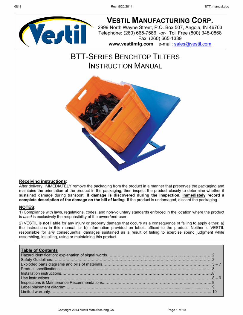
0813 Rev. 5/20/2014 BTT, manual.doc Copyright 2014 Vestil Manufacturing Co. Page 1 of 10 BTT-SERIES BENCHTOP TILTERS INSTRUCTION MANUAL Receiving instructions: After delivery, IMMEDIATELY remove the packaging from the product in a manner that preserves the packaging and maintains the orientation of the product in the packaging; then inspect the product closely to determine whether it sustained damage during transport. If damage is discovered during the inspection, immediately record a complete description of the damage on the bill of lading. If the product is undamaged, discard the packaging. NOTES: 1) Compliance with laws, regulations, codes, and non-voluntary standards enforced in the location where the product is used is exclusively the responsibility of the owner/end-user. 2) VESTIL is not liable for any injury or property damage that occurs as a consequence of failing to apply either: a) the instructions in this manual; or b) information provided on labels affixed to the product. Neither is VESTIL responsible for any consequential damages sustained as a result of failing to exercise sound judgment while assembling, installing, using or maintaining this product. Table of Contents Hazard identification: explanation of signal words……………………………………………………………………. 2 Safety Guidelines…………………………………………………………………………..…………………….………. 2 Exploded parts diagrams and bills of materials……………………………………………………………………….. 3 – 7 Product specifications……………………………………………………………………………………………………. 8 Installation instructions……………………………………………………………………………………………………8 Use instructions……………………………………………………………………………………………………………8 – 9 Inspections & Maintenance Recommendations………………………………………………………………………. 9 Label placement diagram ………….. …………………………………………………………................................. 9 Limited warranty………………………………………………………………………………………………………….. 10 VESTIL MANUFACTURING CORP. 2999 North Wayne Street, P.O. Box 507, Angola, IN 46703 Telephone: (260) 665-7586 -or- Toll Free (800) 348-0868 Fax: (260) 665-1339 www.vestilmfg.com e-mail: [email protected]
Transcript of VESTIL MANUFACTURING CORP MANUAL.pdf · NOTES: 1) Compliance with laws, ... 0813 Rev. 5/20/2014...
0813 Rev. 5/20/2014 BTT, manual.doc
Copyright 2014 Vestil Manufacturing Co. Page 1 of 10
BTT-SERIES BENCHTOP TILTERS INSTRUCTION MANUAL
Receiving instructions: After delivery, IMMEDIATELY remove the packaging from the product in a manner that preserves the packaging and maintains the orientation of the product in the packaging; then inspect the product closely to determine whether it sustained damage during transport. If damage is discovered during the inspection, immediately record a complete description of the damage on the bill of lading. If the product is undamaged, discard the packaging.
NOTES: 1) Compliance with laws, regulations, codes, and non-voluntary standards enforced in the location where the product is used is exclusively the responsibility of the owner/end-user.
2) VESTIL is not liable for any injury or property damage that occurs as a consequence of failing to apply either: a) the instructions in this manual; or b) information provided on labels affixed to the product. Neither is VESTIL responsible for any consequential damages sustained as a result of failing to exercise sound judgment while assembling, installing, using or maintaining this product.
Table of Contents Hazard identification: explanation of signal words……………………………………………………………………. 2 Safety Guidelines…………………………………………………………………………..…………………….………. 2 Exploded parts diagrams and bills of materials……………………………………………………………………….. 3 – 7 Product specifications……………………………………………………………………………………………………. 8 Installation instructions…………………………………………………………………………………………………… 8 Use instructions…………………………………………………………………………………………………………… 8 – 9 Inspections & Maintenance Recommendations………………………………………………………………………. 9 Label placement diagram ………….. …………………………………………………………................................. 9 Limited warranty………………………………………………………………………………………………………….. 10
VESTIL MANUFACTURING CORP. 2999 North Wayne Street, P.O. Box 507, Angola, IN 46703 Telephone: (260) 665-7586 -or- Toll Free (800) 348-0868
Fax: (260) 665-1339 www.vestilmfg.com e-mail: [email protected]
0813 Rev. 5/20/2014 BTT, manual.doc
Copyright 2014 Vestil Manufacturing Co. Page 2 of 10
HAZARD IDENTIFICATION: explanation of signal words This manual uses SIGNAL WORDS to indicate the likelihood of personal injuries, as well as the probable
seriousness of those injuries, if the product is misused in the ways described. Other signal words call attention to uses of the product likely cause property damage.
The signal words used appear below along with the meaning of each word:
Identifies a hazardous situation which, if not avoided, WILL result in DEATH or SERIOUS INJURY. Use of this signal word is limited to the most extreme situations.
Identifies a hazardous situation which, if not avoided, COULD result in DEATH or SERIOUS INJURY.
Indicates a hazardous situation which, if not avoided, COULD result in MINOR or MODERATE injury.
Identifies practices likely to result in product/property damage, such as operation that might damage the product.
Safety Guidelines VESTIL strives to identify foreseeable hazards associated with the use of its products. However, material handling
is inherently dangerous and no manual can address every conceivable risk. The end-user ultimately is responsible for exercising sound judgment at all times.
If this product is used improperly or carelessly, the operator and/or bystanders might sustain serious personal injuries or even be killed. Each operator should read and understand the entire manual before installing, using or servicing the product for the first time. Failure to do so is a misuse of the product. If you do not understand an instruction, ask your supervisor for clarification because failure to adhere to the directions in this manual might result in serious personal injury. To reduce the likelihood of injury: Read the manual to refresh your understanding of proper use and maintenance procedures. DO NOT attempt to resolve any problem with the product unless you are both authorized to do so and certain that it will be safe to use afterwards. DO NOT modify the product in any way UNLESS you first obtain written approval from VESTIL. Unauthorized modifications automatically void the Limited Warranty and might make the product unsafe to use. Inspect the product regularly (also see “Maintenance recommendations” on p. 10) to confirm normal condition. A. DO NOT use this product if the inspection reveals structural damage. Examples of structural damage include,
but are not limited to, the following: 1) Cracked, broken or significantly deformed load-bearing members; 2) cracked welds; 3) corrosion, severe wear, or other condition that affects the ability of the product to support weight or itself. Replace each part that fails to pass an inspection, and DO NOT use the product until it is fully restored to normal condition.
B. DO NOT use the product if any unusual noise or movement is observed. If a malfunction occurs, remove the unit from service and notify your supervisor & maintenance personnel about the issue.
DO NOT exceed the capacity of the tilter (see “Product specifications” table on p. ## and “Label placement diagram” on p. 10). DO NOT stand, or allow other persons to stand, reach, or crawl beneath any elevated part of the tilter. DO NOT modify the drum carrier or any component of the lifter in any way UNLESS you first obtain written approval from Vestil. Unauthorized modifications automatically void the Limited Warranty (p. 11) and might make the device unsafe to use. DO NOT use the carrier UNLESS all product labels (see “Label placement diagram” on p. 10) are readable and undamaged.
Proper use, maintenance, and storage are essential for this product to function properly. o Always use this product in accordance with the instructions in this manual and consistent with any training relevant to machines, devices, etc. used in conjunction with this product. o Keep the product clean & dry. Periodically lubricate moving parts.

0813 Rev. 5/20/2014 BTT, manual.doc
Copyright 2014 Vestil Manufacturing Co. Page 3 of 10
FIG. 1: BTT-5-36 Exploded Parts Diagram & Bill of Materials
Item no. Part no. Description Quantity1 03-514-004 Frame assembly 1 2 03-512-002 Hinge link assembly 1 3 03-513-006 28in. x 36in. deck subassembly 1 4 37024 3/8 in. - 16 Nylock nut 7 5 11110 3/8 in. - 16 x 1¾in. HHCS #2 zinc-plated bolt 5 6 33082 3/8 in. zinc-plated SAE flat washer 16 7 03-148-001 Linear actuator (BTT-500) 1 8 37027 7/16 in. - 14 zinc-plated Nylock nut 1 9 24095 3/8 in. - 16 x 1¾in. UNC BHSCS bolt 2 10 68083 Steel E-clip for 5/8 in. shaft 2 11 20-110-006 Roller bearing CA-40-2/4/6 2 12 21-113-021 Bearing shaft spacer 2 13 33084 7/16 in. SAE flat washer 2 14 13159 7/16 in. - 14 x 2½in. HHCS #5 zinc-plated 1 15 03-148-002-001 Control box 1

0813 Rev. 5/20/2014 BTT, manual.doc
Copyright 2014 Vestil Manufacturing Co. Page 4 of 10
FIG. 2: BTT-5-46 Exploded Parts Diagram & Bill of Materials
Item no. Part no. Description Quantity 1 03-514-004 Frame assembly 1 2 03-513-007 28in. x 46in. deck subassembly 1 3 03-512-002 Hinge link assembly 1 4 11110 3/8 in. - 16 x 1¾in. HHCS #2 zinc-plated bolt 5 5 37024 3/8 in. - 16 Nylock nut 7 6 33082 3/8 in. zinc-plated SAE flat washer 16 7 03-148-001 Linear actuator (BTT-500) 1 8 24095 3/8 in. - 16 x 1¾in. UNC BHSCS bolt 2 9 68083 Steel E-clip for 5/8 in. shaft 2 10 20-110-006 Roller bearing CA-40-2/4/6 2 11 21-113-021 Bearing shaft spacer 2 12 03-148-002-001 Control box 1 13 33084 7/16 in. SAE flat washer 2 14 13159 7/16 in. - 14 x 2½in. HHCS #5 zinc-plated 1 15 37027 7/16 in. - 14 zinc-plated Nylock nut 1

0813 Rev. 5/20/2014 BTT, manual.doc
Copyright 2014 Vestil Manufacturing Co. Page 5 of 10
FIG. 3: BTT-6-36 and BTT-6-46 Exploded Parts Diagram & Bills of Materials
BTT-6-36 Bill of Materials:
BTT-6-46 Bill of Materials:
Item no. Part no. Description Quantity 1 03-514-002 Base frame subassembly 1 2 03-510-003 Cross-bar support subassembly 1 3 03-513-003 28in. x 36in. deck subassembly 1 4 11105 7/16 in. - 16 x 1in. HHCS #2 zinc-plated bolt 4 5 37024 3/8 in. - 16 zinc-plated Nylock nut 4
Item no. Part no. Description Quantity 1 03-514-002 Base frame subassembly 1 2 03-510-003 Cross-bar support subassembly 1 3 03-513-004 28in. x 46in. deck subassembly 1 4 11105 7/16 in. - 16 x 1in. HHCS #2 zinc-plated bolt 4 5 37024 3/8 in. - 16 zinc-plated Nylock nut 4

0813 Rev. 5/20/2014 BTT, manual.doc
Copyright 2014 Vestil Manufacturing Co. Page 6 of 10
FIG. 4: BTT-10-36 Exploded Parts Diagram & Bill of Materials
Item no. Part no. Description Quantity
1 03-002-009 Final assembly without power 1 2 03-148-002 Linear actuator (BTT-1000) 1 3 03-524-001 Actuator guard assembly 1 4 03-112-006 Cylinder pin 1 5 01-034-021 Rubber grommet 1 6 37024 3/8 in. -16 Nylock nut 1 7 33082 3/8 in. zinc-plated SAE flat washer 2 8 37015 10-32 zinc-plated Nylock nut 3 9 24213 #10-32 x 1in. flat head socket cap screw 3 10 11109 3/8 in. - 16 x 1½in. HHCS #2 zinc-plated bolt 1 11 32415 5/16 in. - 18 x ½in. zinc-plated, type F, thread cutting screw 3 12 16-145-002 ½ in. Tinnerman fastner 2 13 03-148-002-001 Control box 1

0813 Rev. 5/20/2014 BTT, manual.doc
Copyright 2014 Vestil Manufacturing Co. Page 7 of 10
FIG. 5: BTT-10-46 Exploded Parts Diagram & Bill of Materials
Item no. Part no. Description Quantity 1 03-148-002 Linear actuator (BTT-1000) 1 2 03-524-001 Actuator guard assembly 1 3 03-112-006 Cylinder pin 1 4 16-145-002 ½ in. Tinnerman fastner 2 5 01-034-021 Rubber grommet 1 6 24213 #10-32 x 1in. flat head socket cap screw 3 7 37015 10-32 zinc-plated Nylock nut 3 8 32415 5/16 in. - 18 x ½in. zinc-plated, type F, thread cutting screw 3 9 33082 3/8 in. zinc-plated SAE flat washer 2 10 37024 3/8 in. -16 Nylock nut 1 11 11109 3/8 in. - 16 x 1½in. HHCS #2 zinc-plated bolt 1 12 03-148-002-001 Control box 1 13 03-002-012 Final assembly without power 1

0813 Rev. 5/20/2014 BTT, manual.doc
Copyright 2014 Vestil Manufacturing Co. Page 8 of 10
Product specifications Dimensions and other specifications appear in the table below:
Model Platform dimensions
(W x L x H) Capacity
Possible angles of inclination
Mode of operation
Net weight
BTT-6-36 28in. x 36in. x 2in.
71.1cm x 91.4cm x 5.1cm 600 lb.
272.7 kg 15°; 30°; and 45° Manual
60 lb. 27.3 kg
BTT-6-46 28in. x 46in. x 2in.
71.1cm x 116.8cm x 5.1cm 600 lb.
272.7 kg 15°; 30°; and 45° Manual
72 lb. 32.7 kg
BTT-5-36 28in. x 36in. x 5in.
71.1cm x 91.4cm x 12.7cm 500 lb.
227.3 kg Adjustable from 0°
through 45° Powered by
linear actuator 84 lb.
38.2 kg
BTT-5-46 28in. x 46in. x 5in.
71.1cm x 116.8cm x 12.7cm 500 lb.
227.3 kg Adjustable from 0°
through 45° Powered by
linear actuator 96 lb.
43.6 kg
BTT-10-36 28in. x 36in. x 3in.
71.1cm x 91.4cm x 7.6cm 1,000 lb. 454.5 kg
Adjustable from 0° through 45°
Powered by linear actuator
96 lb. 43.6 kg
BTT-10-46 28in. x 46in. x 3in.
71.1cm x 116.8cm x 7.6cm 1,000 lb. 454.5 kg
Adjustable from 0° through 45°
Powered by linear actuator
108 lb. 49.1 kg
Installation To install the tilter, fasten it to the selected surface with 3/8in. bolts and corresponding hardware of appropriate length as determined by your building engineer. Insert an anchor bolt through each of the 4 bolt slots in the frame (see FIG. 6 below).
Using the tilter
Orient the load with its long axis parallel to the surface of the deck to prevent it from rolling over the lip of the deck. DO NOT exceed the capacity, which is listed in the table on p. 3 and displayed on label 287 (see “Label placement diagram” on p. 10).
Manually-actuated models (BTT-6-36 & BTT-6-46) The deck of both manually-actuated models can be set in 4 positions:
1. Horizontal 2. 15 degrees to horizontal; 3. 30 degrees to horizontal; and 4. 45 degrees to horizontal.
To change the angle of the deck, lift the deck by the handle then seat the crossbar in the appropriate slots in the frame. The angle of inclination corresponding to each set of slot is diagrammed below.
Slot 1 = 15° inclination
Slot 2 = 30° inclination
Slot 3 = 45° inclination
Crossbar support
Deck
Handle
Deck lip
Anchor bolt holes
2
3
1
NOTE: User should be able to comfortably lift 40 pounds. Ask for assistance, if necessary, to lift the deck.
FIG. 6: Installation and use
0813 Rev. 5/20/2014 BTT, manual.doc
Copyright 2014 Vestil Manufacturing Co. Page 9 of 10
Power-actuated models (BTT 5-36; BTT-5-46; BTT-10-36; & BTT-10-46 The deck can be inclined at any angle from zero up to 45 degrees. To incline the deck, simply press the “UP” pushbutton on the pendant controller until the deck achieves the degree of tilt desired. To decrease the angle, press the “DOWN” button. Always return the deck to the horizontal configuration before leaving the tilter unattended.
Inspections & Maintenance Recommendations Inspect the tilter at least as frequently as indicated in this section to confirm that the tilter is in normal operating condition. Before each use, inspect the listed components. Do not use the tilter unless all components are in normal condition:
1. Frame assembly: confirm that the frame is securely anchored to the surface. 2. Hinge link assembly (powered units): confirm that the link assembly is not warped or cracked 3. Electrical cords (powered models): check the cords for damage. 4. Crossbar support (manual models): examine the crossbar and confirm that it is structurally sound.
For example, it should not be warped, cracked, bent, or excessively rusted or corroded. 5. Product labels: all labels should be readable and located as shown in FIG. 6. If a label(s) is
unreadable or missing, contact Vestil to order a replacement. At least 1 time per month, inspect:
1. Fasteners (hardware): anchoring hardware, bolts, nuts, washers, pins, washers, etc. Tighten loose fasteners and replace any fastener that is damaged;
2. Handle: confirm that the handle is structurally sound, uncorroded and free of rust. 3. Welds: confirm that all welds are intact. 4. Linear actuator: cycle the actuator to confirm normal operation. Incline the deck to 45 degrees and
return the deck to the horizontal configuration, while: a. Listening for unusual noises. b. Watching the motion of the deck. Motion should be smooth and continuous.
Partly incline the deck and confirm that the actuator maintains deck position, i.e. the deck should not lower on its own.
5. Overall condition of the tilter: the structure should be clean, square and rigid, and free of rust and corrosion. Remove dirt and debris.
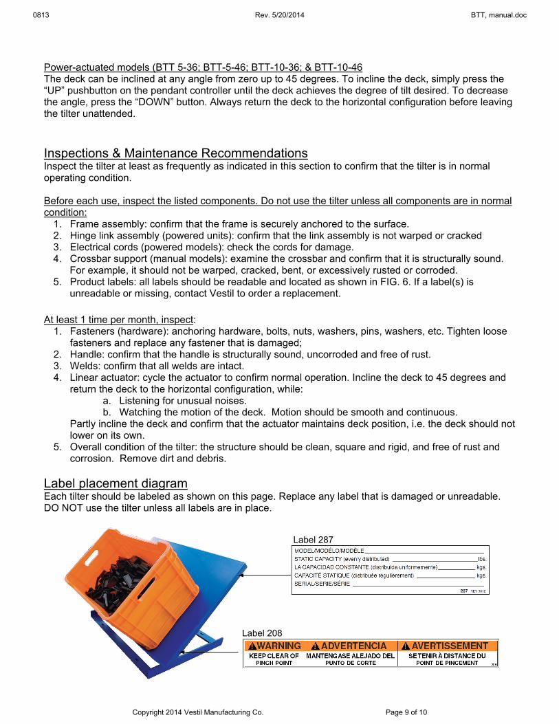
Label placement diagram Each tilter should be labeled as shown on this page. Replace any label that is damaged or unreadable. DO NOT use the tilter unless all labels are in place.
Label 287
Label 208

0813 Rev. 5/20/2014 BTT, manual.doc
Copyright 2014 Vestil Manufacturing Co. Page 10 of 10
LIMITED WARRANTY
Vestil Manufacturing Corporation (“Vestil”) warrants this product to be free of defects in material and workmanship during the warranty period. Our warranty obligation is to provide a replacement for a defective original part if the part is covered by the warranty, after we receive a proper request from the warrantee (you) for warranty service.
Who may request service? Only a warrantee may request service. You are a warrantee if you purchased the product from Vestil or from an authorized distributor AND Vestil has been fully paid.
What is an “original part”? An original part is a part used to make the product as shipped to the warrantee.
What is a “proper request”? A request for warranty service is proper if Vestil receives: 1) a photocopy of the Customer Invoice that displays the shipping date; AND 2) a written request for warranty service including your name and phone number. Send requests by any of the following methods:
Mail Fax Email Vestil Manufacturing Corporation (260) 665-1339 [email protected] 2999 North Wayne Street, PO Box 507 Phone Angola, IN 46703 (260) 665-7586
In the written request, list the parts believed to be defective and include the address where replacements should be delivered.
What is covered under the warranty? After Vestil receives your request for warranty service, an authorized representative will contact you to determine whether your claim is covered by the warranty. Before providing warranty service, Vestil may require you to send the entire product, or just the defective part or parts, to its facility in Angola, IN. The warranty covers defects in the following original dynamic components: motors, hydraulic pumps, electronic controllers, switches and cylinders. It also covers defects in original parts that wear under normal usage conditions (“wearing parts”), such as bearings, hoses, wheels, seals, brushes, and batteries.
How long is the warranty period? The warranty period for original components is 1 year. The warranty period begins on the date when Vestil ships the product to the warrantee. If the product was purchased from an authorized distributor, the period begins when the distributor ships the product. Vestil may extend the warranty period for products shipped from authorized distributors by up to 30 days to account for shipping time.
If a defective part is covered by the warranty, what will Vestil do to correct the problem? Vestil will provide an appropriate replacement for any covered part. An authorized representative of Vestil will contact you to discuss your claim.
What is not covered by the warranty? 1. Labor; 2. Freight; 3. Occurrence of any of the following, which automatically voids the warranty:
Product misuse; Negligent operation or repair; Corrosion or use in corrosive environments; Inadequate or improper maintenance; Damage sustained during shipping; Collisions or other incidental contacts causing damage to the product; Unauthorized modifications: DO NOT modify the product IN ANY WAY without first receiving written
authorization from Vestil. Modification(s) might make the product unsafe to use or might cause excessive and/or abnormal wear.
Do any other warranties apply to the product? Vestil Manufacturing Corp. makes no other express warranties. All implied warranties are disclaimed to the extent allowed by law. Any implied warranty not disclaimed is limited in scope to the terms of this Limited Warranty.