
VESA CVT Standard
21
VESA Coordinated Video Timings Standard Version 1.1 ©Copyright 2003 Video Electronics Standards Association Page 1 of 21 VESA® CVT Standard Video Electronics Standards Association 860 Hillview Court, Suite 150 Phone: (408) 957-9270 Milpitas, CA 95035 Fax: (408) 957-9277 Coordinated Video Timings Standard Version 1.1 September 10, 2003 Purpose The VESA Coordinated Video Timings (CVT) is a method for generating a consistent and coordinated set of standard formats, display refresh rates, and timing specifications for computer display products, both those employing CRTs and those using other display technologies. The intention of the CVT specification is to give both source and display manufacturers a common set of tools to enable new timings to be developed in a consistent manner that ensure greater compatibility. Summary The CVT Standard defines rules and methods by which new and existing formats can be defined. Based primarily on the VESA GTF Standard, CVT defines restrictions to the pixel clock modularity, refresh rate and aspect ratio. It also specifies a new equation-based method for developing Reduced Blanking timings, designed for use with non-CRT displays that can accept Reduced Horizontal Blanking times.
Transcript of VESA CVT Standard
VESA Coordinated Video Timings Standard Version 1.1 ©Copyright 2003 Video Electronics Standards Association Page 1 of 21
VESA® CVT Standard Video Electronics Standards Association 860 Hillview Court, Suite 150 Phone: (408) 957-9270 Milpitas, CA 95035 Fax: (408) 957-9277
Coordinated Video Timings Standard Version 1.1
September 10, 2003
Purpose The VESA Coordinated Video Timings (CVT) is a method for generating a consistent and coordinated set of standard formats, display refresh rates, and timing specifications for computer display products, both those employing CRTs and those using other display technologies. The intention of the CVT specification is to give both source and display manufacturers a common set of tools to enable new timings to be developed in a consistent manner that ensure greater compatibility. Summary The CVT Standard defines rules and methods by which new and existing formats can be defined. Based primarily on the VESA GTF Standard, CVT defines restrictions to the pixel clock modularity, refresh rate and aspect ratio. It also specifies a new equation-based method for developing Reduced Blanking timings, designed for use with non-CRT displays that can accept Reduced Horizontal Blanking times.
VESA Coordinated Video Timings Standard Version 1.1 ©Copyright 2003 Video Electronics Standards Association Page 2 of 21
Preface Intellectual Property Copyright © 2003 Video Electronics Standards Association. All rights reserved. While every precaution has been taken in the preparation of this standard, the Video Electronics Standards Association and its contributors assume no responsibility for errors or omissions, and make no warranties, expressed or implied, of functionality or suitability for any purpose. Trademarks All trademarks used within this document are the property of their respective owners. VESA, DDC, EDID, and E-EDID trademarks of the Video Electronics Standard Association. I2C is a trademark owned by Philips. Patents VESA proposals and standards are adopted by the Video Electronics Standards Association without regard as to whether their adoption may involve any patents or articles, materials, or processes. Such adoption does not assume any liability to any patent owner, nor does it assume any obligation whatsoever to parties adopting the proposals or standards documents. Support for this Standard Clarifications and application notes to support this standard may be written. To obtain the latest standard and any support documentation, contact VESA. If you have a product, which incorporates CVT, you should ask the company that manufactured your product for assistance. If you are a manufacturer, VESA can assist you with any clarification you may require. All comments or reported errors should be submitted in writing to VESA using one of the following methods. • Fax : 408-957 9277, direct this note to Technical Support at VESA • e-mail: [email protected] • mail: Technical Support Video Electronics Standards Association 860 Hillview Court, Suite 150 Milpitas, CA 95035
VESA Coordinated Video Timings Standard Version 1.1 ©Copyright 2003 Video Electronics Standards Association Page 3 of 21
Revision History Version 1.1 September 10, 2003 Section 3.4.1, points 6 & 7 revised to correct mistake (minimum Vertical Sync and Vertical Back Porch time is 550us not 500us). Rounding errors in VESA Standard Names corrected in Table 3 and 7. Missing Constants and Variables added to Table 9 and 10. Version 1 March 26, 2003 Initial release of the standard Acknowledgements This document would not have been possible without the efforts of the VESA Display Committee. In particular, the following individuals and their companies contributed significant time and knowledge to this version of the CVT Standard. David Glen ATI Technologies, Inc. Jory Olson InFocus
Joe Goodart Dell Computer Corp. Hiroshi Yamashita International Display Tech.
Shiro Makino Eizo Nanao Corporation Keita Kitahama NVIDIA Corp.
Graham Loveridge, Workgroup Leader
Genesis Microchip Nozomu Kikuchi Pioneer Corporation
Steve Hasegawa Sony
Jim Webb Genesis Microchip Joe Miseli Sun Microsystems
Youichi Igarashi Hitachi Ltd. Don Chambers Total Technologies Ltd.
VESA Coordinated Video Timings Standard Version 1.1 ©Copyright 2003 Video Electronics Standards Association Page 4 of 21
Table of Contents REVISION HISTORY................................................................................................................................................3 1. OVERVIEW ........................................................................................................................................................5 1.1 SUMMARY ..........................................................................................................................................................5 1.2 BACKGROUND ....................................................................................................................................................5 1.3 STANDARD OBJECTIVES .....................................................................................................................................5 1.4 REFERENCE DOCUMENTS ...................................................................................................................................6 2. FORMAT & TIMING SELECTION ................................................................................................................7 2.1 FORMAT SELECTION...........................................................................................................................................7 3. TIMING GENERATION ...................................................................................................................................8 3.1 ASPECT RATIO....................................................................................................................................................8 3.2 PIXEL CLOCK SELECTION ...................................................................................................................................8
3.2.1 Minimum Clock Rate for Transmission .....................................................................................................8 3.3 THE STANDARD VERTICAL REFRESH RATE SET .................................................................................................8
3.3.1 Determination of Vertical Refresh Rate Error...........................................................................................9 3.4 RULES FOR TIMING GENERATION .......................................................................................................................9
3.4.1 Standard “CRT” based Timing .................................................................................................................9 3.4.2 Reduced Blanking Timing........................................................................................................................10
3.5 LOCKING TO EXTERNAL TIMING SOURCES .......................................................................................................11 3.6 SYNC POLARITIES.............................................................................................................................................11 4. VESA STANDARD DISPLAY FORMATS....................................................................................................13 4.1 OVERVIEW........................................................................................................................................................13 4.2 VESA FORMAT NAMING CONVENTION............................................................................................................13 4.3 VESA STANDARD 4:3 FORMATS ......................................................................................................................14 4.4 VESA STANDARD 5:4 FORMATS ......................................................................................................................14 4.5 VESA STANDARD 15:9 FORMATS ....................................................................................................................14 4.6 VESA STANDARD 16:9 FORMATS ....................................................................................................................15 4.7 VESA STANDARD 16:10 FORMATS ..................................................................................................................15 5. COMPUTATION OF TIMING PARAMETERS ..........................................................................................16 5.1 EXPLANATION OF TERMS..................................................................................................................................16 5.2 COMPUTATION OF COMMON PARAMETERS.......................................................................................................16 5.3 COMPUTATION OF "CRT" TIMING PARAMETERS ..............................................................................................17 5.4 COMPUTATION OF REDUCED BLANKING TIMING PARAMETERS........................................................................18 5.5 DEFINITION OF CONSTANTS & VARIABLES.......................................................................................................18
Tables Table 1: Sync Polarities...............................................................................................................................................11 Table 2: Vertical Sync Duration..................................................................................................................................12 Table 3: Examples of 4:3 Formats...............................................................................................................................14 Table 4: Standard 5:4 Formats.....................................................................................................................................14 Table 5: Standard 15:9 Formats...................................................................................................................................14 Table 6: Examples of 16:9 Formats.............................................................................................................................15 Table 7: Examples of 16:10 Formats...........................................................................................................................15 Table 8: Expression Terms & Operator.......................................................................................................................16 Table 9: Definition of Constants .................................................................................................................................18 Table 10: Definition of Variables................................................................................................................................19
VESA Coordinated Video Timings Standard Version 1.1 ©Copyright 2003 Video Electronics Standards Association Page 5 of 21
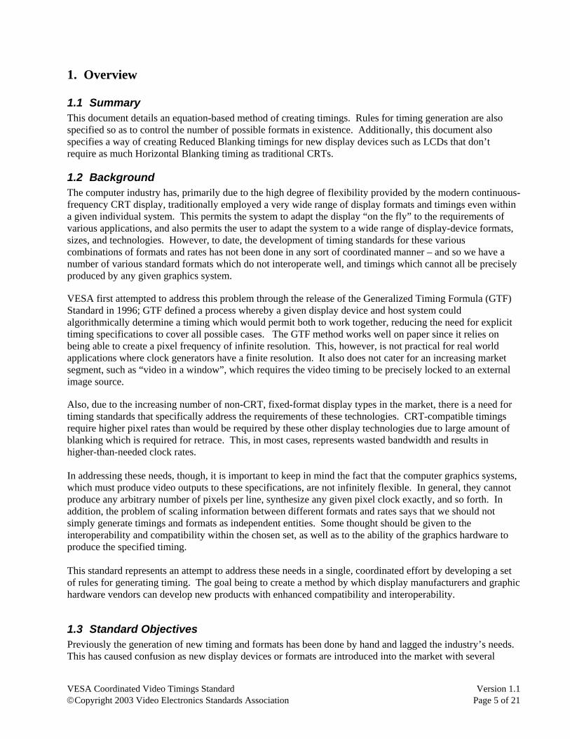
1. Overview
1.1 Summary This document details an equation-based method of creating timings. Rules for timing generation are also specified so as to control the number of possible formats in existence. Additionally, this document also specifies a way of creating Reduced Blanking timings for new display devices such as LCDs that don’t require as much Horizontal Blanking timing as traditional CRTs.
1.2 Background The computer industry has, primarily due to the high degree of flexibility provided by the modern continuous-frequency CRT display, traditionally employed a very wide range of display formats and timings even within a given individual system. This permits the system to adapt the display “on the fly” to the requirements of various applications, and also permits the user to adapt the system to a wide range of display-device formats, sizes, and technologies. However, to date, the development of timing standards for these various combinations of formats and rates has not been done in any sort of coordinated manner – and so we have a number of various standard formats which do not interoperate well, and timings which cannot all be precisely produced by any given graphics system. VESA first attempted to address this problem through the release of the Generalized Timing Formula (GTF) Standard in 1996; GTF defined a process whereby a given display device and host system could algorithmically determine a timing which would permit both to work together, reducing the need for explicit timing specifications to cover all possible cases. The GTF method works well on paper since it relies on being able to create a pixel frequency of infinite resolution. This, however, is not practical for real world applications where clock generators have a finite resolution. It also does not cater for an increasing market segment, such as “video in a window”, which requires the video timing to be precisely locked to an external image source. Also, due to the increasing number of non-CRT, fixed-format display types in the market, there is a need for timing standards that specifically address the requirements of these technologies. CRT-compatible timings require higher pixel rates than would be required by these other display technologies due to large amount of blanking which is required for retrace. This, in most cases, represents wasted bandwidth and results in higher-than-needed clock rates. In addressing these needs, though, it is important to keep in mind the fact that the computer graphics systems, which must produce video outputs to these specifications, are not infinitely flexible. In general, they cannot produce any arbitrary number of pixels per line, synthesize any given pixel clock exactly, and so forth. In addition, the problem of scaling information between different formats and rates says that we should not simply generate timings and formats as independent entities. Some thought should be given to the interoperability and compatibility within the chosen set, as well as to the ability of the graphics hardware to produce the specified timing. This standard represents an attempt to address these needs in a single, coordinated effort by developing a set of rules for generating timing. The goal being to create a method by which display manufacturers and graphic hardware vendors can develop new products with enhanced compatibility and interoperability.
1.3 Standard Objectives Previously the generation of new timing and formats has been done by hand and lagged the industry’s needs. This has caused confusion as new display devices or formats are introduced into the market with several

VESA Coordinated Video Timings Standard Version 1.1 ©Copyright 2003 Video Electronics Standards Association Page 6 of 21
different timings. The purpose of CVT is to define a method of creating timings so that new timings can be created simply and easily. CVT provides a coordinated approach so that timing source generators and display devices know what the requirements for producing new timings will be and can provide forward compatibility to formats not yet conceived.
In addition, this standard also provides a way to generate timing with Reduced Blanking. This enables newer display devices, such as LCDs, which don’t require as much blanking as CRTs, to reduce the pixel rate and use the transmission bandwidth from the source to the display more efficiently.
The long-term goal of CVT is to replace existing DMTs (Display Monitor Timings) and become the standard method for generating new timings. It will also enable increased automation of creating published lists of DMTs that are generated using the CVT method.
1.4 Reference Documents • VESA Enhanced Extended Display Identification Data Standard – E-EDID, Release A, Sept. 2, 1999 • VESA Enhanced Display Data Channel Standard - E-DDC, Version 1, Sept. 2, 1999 • VESA Generalized Timing Formula Standard - GTF, Version 1.0, Dec. 18, 1996 • VESA and Industry Standards and Guidelines for Computer Display Monitor Timings – DMT, Version
1.0, Rev. 0.8, Sept. 17, 1998. • VESA E-EDID Implementation Guide, Version 1.0, June 2, 2001
VESA Coordinated Video Timings Standard Version 1.1 ©Copyright 2003 Video Electronics Standards Association Page 7 of 21
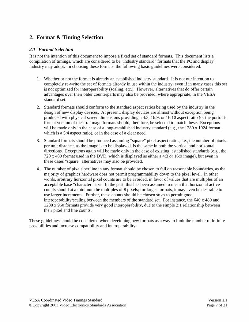
2. Format & Timing Selection
2.1 Format Selection It is not the intention of this document to impose a fixed set of standard formats. This document lists a compilation of timings, which are considered to be "industry standard" formats that the PC and display industry may adopt. In choosing these formats, the following basic guidelines were considered:
1. Whether or not the format is already an established industry standard. It is not our intention to completely re-write the set of formats already in use within the industry, even if in many cases this set is not optimized for interoperability (scaling, etc.). However, alternatives that do offer certain advantages over their older counterparts may also be provided, where appropriate, in the VESA standard set.
2. Standard formats should conform to the standard aspect ratios being used by the industry in the design of new display devices. At present, display devices are almost without exception being produced with physical screen dimensions providing a 4:3, 16:9, or 16:10 aspect ratio (or the portrait-format version of these). Image formats should, therefore, be selected to match these. Exceptions will be made only in the case of a long-established industry standard (e.g., the 1280 x 1024 format, which is a 5:4 aspect ratio), or in the case of a clear need.
3. Standard formats should be produced assuming “square” pixel aspect ratios, i.e., the number of pixels per unit distance, as the image is to be displayed, is the same in both the vertical and horizontal directions. Exceptions again will be made only in the case of existing, established standards (e.g., the 720 x 480 format used in the DVD, which is displayed as either a 4:3 or 16:9 image), but even in these cases “square” alternatives may also be provided.
4. The number of pixels per line in any format should be chosen to fall on reasonable boundaries, as the majority of graphics hardware does not permit programmability down to the pixel level. In other words, arbitrary horizontal pixel counts are to be avoided, in favor of values that are multiples of an acceptable base “character” size. In the past, this has been assumed to mean that horizontal active counts should at a minimum be multiples of 8 pixels; for larger formats, it may even be desirable to use larger increments. Further, these counts should be chosen so as to permit good interoperability/scaling between the members of the standard set. For instance, the 640 x 480 and 1280 x 960 formats provide very good interoperability, due to the simple 2:1 relationship between their pixel and line counts.
These guidelines should be considered when developing new formats as a way to limit the number of infinite possibilities and increase compatibility and interoperability.

VESA Coordinated Video Timings Standard Version 1.1 ©Copyright 2003 Video Electronics Standards Association Page 8 of 21
3. Timing Generation
3.1 Aspect Ratio As described in Section 2.1, item 2, the number of aspect ratios for new formats shall be limited to 4:3, 16:9 and 16:10. Sections 4.3 through 4.7 list these aspect ratios and also detail other existing aspect ratios that are considered “industry standards” due to their wide spread use. These “industry standard” aspect ratios should not be propagated within the industry to new timings. Only the standard set listed above should be used when generating new timings.
3.2 Pixel Clock Selection Due to the finite precision of modern clock synthesis circuitry, the pixel clocks used will all be members of a specified set, in this case integer multiples of 0.25 MHz +/- 0.5%. The only exception to this is when there is a need to lock to an external source, for example, “video in a window” applications. In these instances, the pixel clock rate shall be derived from the external source. See section 3.5 for more details.
3.2.1 Minimum Clock Rate for Transmission For some transmission links, the calculated CVT pixel clock may go below a minimum required value. For example certain digital links require a clock rate greater than 25MHz. In these instances the host can double the clock frequency and the calculated horizontal parameters to compensate. If received as digital data, the display will be able to determine clock doubling has taken place by the change in aspect ratio. For analog transmission systems, the increased clock rate will not have any effect since all horizontal timings will still occupy exactly the same time as if they would have if no clock doubling were employed.
3.3 The Standard Vertical Refresh Rate Set With the release of the GTF standard, there is less reason to produce explicit timing specifications for any and all vertical frame, or “refresh”, rates. The real driving force behind standard rates at this time is compatibility with other established image sources and displays – such as television – and to permit the precise synchronization of multiple systems and/or displays while still operating at an ergonomically-acceptable rate. For this reason, the set of standard rates for which timing specifications should be developed will be somewhat restricted. It should be understood that requirements outside of these specific rates could still be addressed by the timing generation rules outlined in this document. For the first release of this standard, the following vertical refresh rates will be used to define the standard set of timings:
• 50.00 Hz – This is a long-established standard rate in European television production and other areas using the PAL or SECAM television systems.
• 60.00 Hz – This rate is a long-established standard; it is reasonably compatible with the standard television field rate used in North America and Japan, and is expected to be one of the standard field/frame rates used under the U.S. digital television broadcasting standard. It is also compatible with 24 FPS film-sourced material, via the “3:2 pull-down” technique.
• 75.00 Hz – This rate maintains good compatibility/interoperability with systems at both the 60 Hz and 50 Hz standard video rates, while providing more ergonomically acceptable performance in many display types. A 75 Hz operation is also compatible with film-sourced material produced under the European 25 FPS standard.
• 85.00 Hz – While not a “video-friendly” rate, 85 Hz has become a de-facto standard for PC displays wishing to meet the strictest ergonomic requirements for a “flicker-free” image. At this rate, the typical CRT-based computer display, under standard viewing conditions, will appear “flicker-free” to greater than 95% of the population.
VESA Coordinated Video Timings Standard Version 1.1 ©Copyright 2003 Video Electronics Standards Association Page 9 of 21
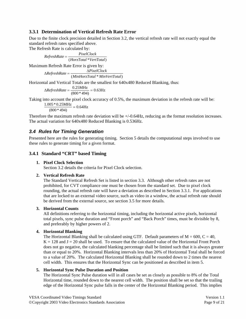
3.3.1 Determination of Vertical Refresh Rate Error Due to the finite clock precision detailed in Section 3.2, the vertical refresh rate will not exactly equal the standard refresh rates specified above. The Refresh Rate is calculated by:
)*( VertTotalHorzTotalPixelClockeRefreshRat =
Maximum Refresh Rate Error is given by:
)*( alMinVertTotalMinHorzTotPixelClockeRefreshRat ∆
=∆
Horizontal and Vertical Totals are the smallest for 640x480 Reduced Blanking, thus:
Hz63.0)494*800(
MHz25.0==∆ eRefreshRat
Taking into account the pixel clock accuracy of 0.5%, the maximum deviation in the refresh rate will be:
Hz64.0)494*800(
MHz25.0*005.1=
Therefore the maximum refresh rate deviation will be +/-0.64Hz, reducing as the format resolution increases. The actual variation for 640x480 Reduced Blanking is 0.536Hz.
3.4 Rules for Timing Generation Presented here are the rules for generating timing. Section 5 details the computational steps involved to use these rules to generate timing for a given format.
3.4.1 Standard “CRT” based Timing
1. Pixel Clock Selection Section 3.2 details the criteria for Pixel Clock selection.
2. Vertical Refresh Rate The Standard Vertical Refresh Set is listed in section 3.3. Although other refresh rates are not prohibited, for CVT compliance one must be chosen from the standard set. Due to pixel clock rounding, the actual refresh rate will have a deviation as described in Section 3.3.1. For applications that are locked to an external video source, such as video in a window, the actual refresh rate should be derived from the external source, see section 3.5 for more details.
3. Horizontal Counts All definitions referring to the horizontal timing, including the horizontal active pixels, horizontal total pixels, sync pulse duration and “Front porch” and “Back Porch” times, must be divisible by 8, and preferably by higher powers of 2.
4. Horizontal Blanking The Horizontal Blanking shall be calculated using GTF. Default parameters of M = 600, C = 40, K = 128 and J = 20 shall be used. To ensure that the calculated value of the Horizontal Front Porch does not go negative, the calculated blanking percentage shall be limited such that it is always greater than or equal to 20%. Horizontal Blanking intervals less than 20% of Horizontal Total shall be forced to a value of 20%. The calculated Horizontal Blanking shall be rounded down to 2 times the nearest cell width. This ensures that the Horizontal Sync can be positioned as described in item 5.
5. Horizontal Sync Pulse Duration and Position The Horizontal Sync Pulse duration will in all cases be set as closely as possible to 8% of the Total Horizontal time, rounded down to the nearest cell width. The position shall be set so that the trailing edge of the Horizontal Sync pulse falls in the center of the Horizontal Blanking period. This implies
VESA Coordinated Video Timings Standard Version 1.1 ©Copyright 2003 Video Electronics Standards Association Page 10 of 21
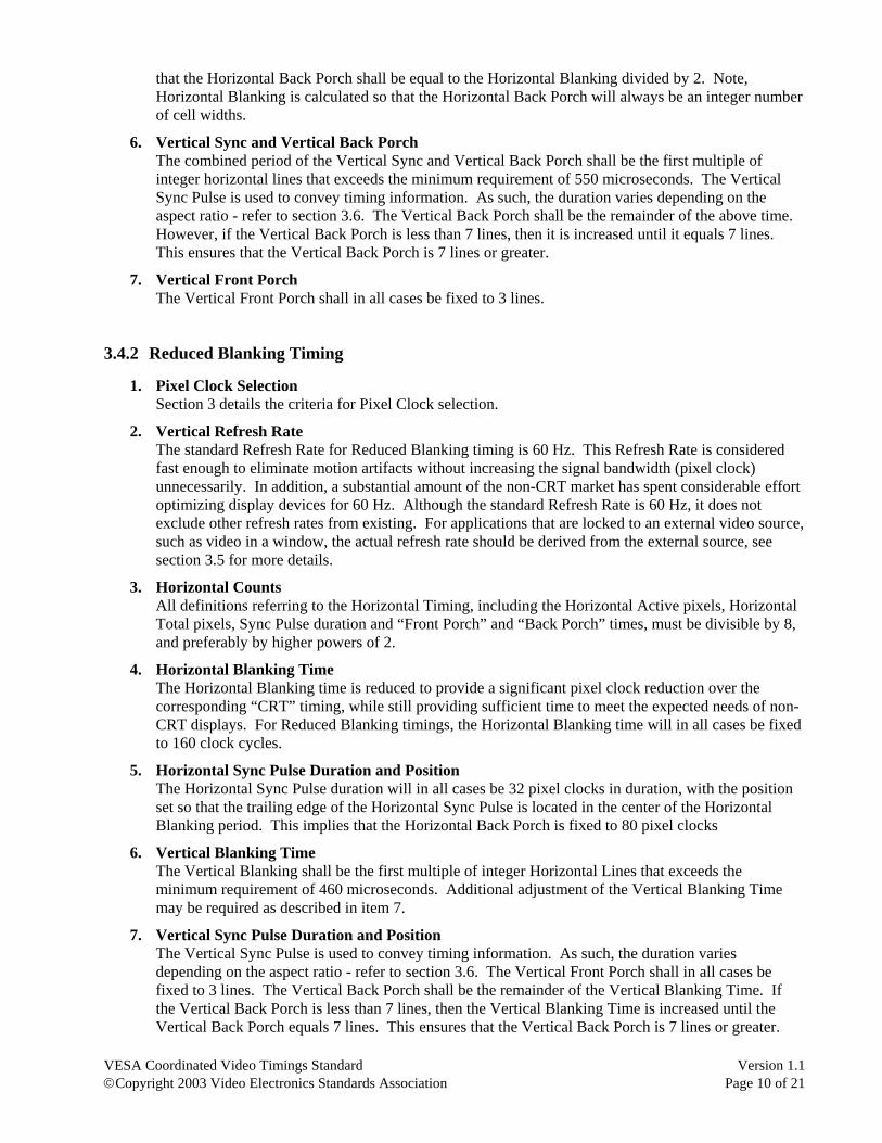
that the Horizontal Back Porch shall be equal to the Horizontal Blanking divided by 2. Note, Horizontal Blanking is calculated so that the Horizontal Back Porch will always be an integer number of cell widths.
6. Vertical Sync and Vertical Back Porch The combined period of the Vertical Sync and Vertical Back Porch shall be the first multiple of integer horizontal lines that exceeds the minimum requirement of 550 microseconds. The Vertical Sync Pulse is used to convey timing information. As such, the duration varies depending on the aspect ratio - refer to section 3.6. The Vertical Back Porch shall be the remainder of the above time. However, if the Vertical Back Porch is less than 7 lines, then it is increased until it equals 7 lines. This ensures that the Vertical Back Porch is 7 lines or greater.
7. Vertical Front Porch The Vertical Front Porch shall in all cases be fixed to 3 lines.
3.4.2 Reduced Blanking Timing
1. Pixel Clock Selection Section 3 details the criteria for Pixel Clock selection.
2. Vertical Refresh Rate The standard Refresh Rate for Reduced Blanking timing is 60 Hz. This Refresh Rate is considered fast enough to eliminate motion artifacts without increasing the signal bandwidth (pixel clock) unnecessarily. In addition, a substantial amount of the non-CRT market has spent considerable effort optimizing display devices for 60 Hz. Although the standard Refresh Rate is 60 Hz, it does not exclude other refresh rates from existing. For applications that are locked to an external video source, such as video in a window, the actual refresh rate should be derived from the external source, see section 3.5 for more details.
3. Horizontal Counts All definitions referring to the Horizontal Timing, including the Horizontal Active pixels, Horizontal Total pixels, Sync Pulse duration and “Front Porch” and “Back Porch” times, must be divisible by 8, and preferably by higher powers of 2.
4. Horizontal Blanking Time The Horizontal Blanking time is reduced to provide a significant pixel clock reduction over the corresponding “CRT” timing, while still providing sufficient time to meet the expected needs of non-CRT displays. For Reduced Blanking timings, the Horizontal Blanking time will in all cases be fixed to 160 clock cycles.
5. Horizontal Sync Pulse Duration and Position The Horizontal Sync Pulse duration will in all cases be 32 pixel clocks in duration, with the position set so that the trailing edge of the Horizontal Sync Pulse is located in the center of the Horizontal Blanking period. This implies that the Horizontal Back Porch is fixed to 80 pixel clocks
6. Vertical Blanking Time The Vertical Blanking shall be the first multiple of integer Horizontal Lines that exceeds the minimum requirement of 460 microseconds. Additional adjustment of the Vertical Blanking Time may be required as described in item 7.
7. Vertical Sync Pulse Duration and Position The Vertical Sync Pulse is used to convey timing information. As such, the duration varies depending on the aspect ratio - refer to section 3.6. The Vertical Front Porch shall in all cases be fixed to 3 lines. The Vertical Back Porch shall be the remainder of the Vertical Blanking Time. If the Vertical Back Porch is less than 7 lines, then the Vertical Blanking Time is increased until the Vertical Back Porch equals 7 lines. This ensures that the Vertical Back Porch is 7 lines or greater.
VESA Coordinated Video Timings Standard Version 1.1 ©Copyright 2003 Video Electronics Standards Association Page 11 of 21
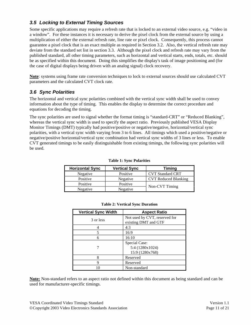
3.5 Locking to External Timing Sources Some specific applications may require a refresh rate that is locked to an external video source, e.g. “video in a window”. For these instances it is necessary to derive the pixel clock from the external source by using a multiplication of either the external refresh rate, line rate or pixel clock. Consequently, this process cannot guarantee a pixel clock that is an exact multiple as required in Section 3.2. Also, the vertical refresh rate may deviate from the standard set list in section 3.3. Although the pixel clock and refresh rate may vary from the published standard, all other timing parameters, such as horizontal and vertical starts, ends, totals, etc. should be as specified within this document. Doing this simplifies the display's task of image positioning and (for the case of digital displays being driven with an analog signal) clock recovery. Note: systems using frame rate conversion techniques to lock to external sources should use calculated CVT parameters and the calculated CVT clock rate.
3.6 Sync Polarities The horizontal and vertical sync polarities combined with the vertical sync width shall be used to convey information about the type of timing. This enables the display to determine the correct procedure and equations for decoding the timing.
The sync polarities are used to signal whether the format timing is “standard-CRT” or “Reduced Blanking”, whereas the vertical sync width is used to specify the aspect ratio. Previously published VESA Display Monitor Timings (DMT) typically had positive/positive or negative/negative, horizontal/vertical sync polarities, with a vertical sync width varying from 3 to 6 lines. All timings which used a positive/negative or negative/positive horizontal/vertical sync combination had vertical sync widths of 3 lines or less. To enable CVT generated timings to be easily distinguishable from existing timings, the following sync polarities will be used.
Table 1: Sync Polarities
Horizontal Sync Vertical Sync Timing Negative Positive CVT Standard CRT Positive Negative CVT Reduced Blanking Positive Positive Negative Negative
Non-CVT Timing
Table 2: Vertical Sync Duration
Vertical Sync Width Aspect Ratio
3 or less Not used by CVT, reserved for existing DMT and GTF
4 4:3 5 16:9 6 16:10
7 Special Case: 5:4 (1280x1024) 15:9 (1280x768)
8 Reserved 9 Reserved
10 Non-standard Note: Non-standard refers to an aspect ratio not defined within this document as being standard and can be used for manufacturer-specific timings.
VESA Coordinated Video Timings Standard Version 1.1 ©Copyright 2003 Video Electronics Standards Association Page 12 of 21
4. VESA Standard Display Formats
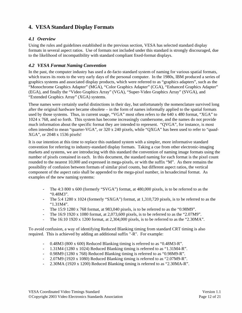
4.1 Overview Using the rules and guidelines established in the previous section, VESA has selected standard display formats in several aspect ratios. Use of formats not included under this standard is strongly discouraged, due to the likelihood of incompatibility with standard compliant fixed-format displays.
4.2 VESA Format Naming Convention In the past, the computer industry has used a de-facto standard system of naming for various spatial formats, which traces its roots to the very early days of the personal computer. In the 1980s, IBM produced a series of graphics systems and associated display products, which were referred to as “graphics adapters”, such as the “Monochrome Graphics Adapter” (MGA), “Color Graphics Adapter” (CGA), “Enhanced Graphics Adapter” (EGA), and finally the “Video Graphics Array” (VGA), “Super-Video Graphics Array” (SVGA), and “Extended Graphics Array” (XGA) systems.
These names were certainly useful distinctions in their day, but unfortunately the nomenclature survived long after the original hardware became obsolete – in the form of names informally applied to the spatial formats used by those systems. Thus, in current usage, “VGA” most often refers to the 640 x 480 format, “XGA” to 1024 x 768, and so forth. This system has become increasingly cumbersome, and the names do not provide much information about the specific format they are intended to represent. “QVGA”, for instance, is most often intended to mean “quarter-VGA”, or 320 x 240 pixels, while “QXGA” has been used to refer to “quad-XGA”, or 2048 x 1536 pixels!
It is our intention at this time to replace this outdated system with a simpler, more informative standard convention for referring to industry-standard display formats. Taking a cue from other electronic-imaging markets and systems, we are introducing with this standard the convention of naming image formats using the number of pixels contained in each. In this document, the standard naming for each format is the pixel count rounded to the nearest 10,000 and expressed in mega-pixels, or with the suffix “M”. As there remains the possibility of confusion between formats of similar pixel counts, but different aspect ratios, the vertical component of the aspect ratio shall be appended to the mega-pixel number, in hexadecimal format. As examples of the new naming systems:
- The 4:3 800 x 600 (formerly “SVGA”) format, at 480,000 pixels, is to be referred to as the “0.48M3”.
- The 5:4 1280 x 1024 (formerly “SXGA”) format, at 1,310,720 pixels, is to be referred to as the “1.31M4”.
- The 15:9 1280 x 768 format, at 983,040 pixels, is to be referred to as the “0.98M9”. - The 16:9 1920 x 1080 format, at 2,073,600 pixels, is to be referred to as the “2.07M9”. - The 16:10 1920 x 1200 format, at 2,304,000 pixels, is to be referred to as the “2.30MA”.
To avoid confusion, a way of identifying Reduced Blanking timing from standard CRT timing is also required. This is achieved by adding an additional suffix "-R". For example:
- 0.48M3 (800 x 600) Reduced Blanking timing is referred to as “0.48M3-R”. - 1.31M4 (1280 x 1024) Reduced Blanking timing is referred to as “1.31M4-R”. - 0.98M9 (1280 x 768) Reduced Blanking timing is referred to as “0.98M9-R”. - 2.07M9 (1920 x 1080) Reduced Blanking timing is referred to as “2.07M9-R”. - 2.30MA (1920 x 1200) Reduced Blanking timing is referred to as “2.30MA-R”.
VESA Coordinated Video Timings Standard Version 1.1 ©Copyright 2003 Video Electronics Standards Association Page 13 of 21
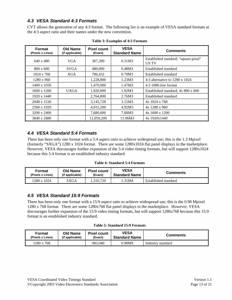
4.3 VESA Standard 4:3 Formats CVT allows the generation of any 4:3 format. The following list is an example of VESA standard formats at the 4:3 aspect ratio and their names under the new convention.
Table 3: Examples of 4:3 Formats
Format (Pixels x Lines)
Old Name (if applicable)
Pixel count(Exact)
VESA Standard Name Comments
640 x 480 VGA 307,200 0.31M3 Established standard; “square-pixel” US TV
800 x 600 SVGA 480,000 0.48M3 Established standard 1024 x 768 XGA 786,432 0.79M3 Established standard 1280 x 960 1,228,800 1.23M3 4:3 alternative to 1280 x 1024
1400 x 1050 1,470,000 1.47M3 4:3 1080-line format 1600 x 1200 UXGA 1,920,000 1.92M3 Established standard; 4x 800 x 600 1920 x 1440 2,764,800 2.76M3 Established standard 2048 x 1536 3,145,728 3.15M3 4x 1024 x 768 2560 x 1920 4,915,200 4.92M3 4x 1280 x 960 3200 x 2400 7,680,000 7.68M3 4x 1600 x 1200 3840 x 2880 11,059,200 11.06M3 4x 1920x1440
4.4 VESA Standard 5:4 Formats There has been only one format with a 5:4 aspect ratio to achieve widespread use; this is the 1.3 Mpixel (formerly “SXGA”) 1280 x 1024 format. There are some 1280x1024 flat panel displays in the marketplace. However, VESA discourages further expansion of the 5:4 video timing formats, but will support 1280x1024 because this 5:4 format is an established industry standard.
Table 4: Standard 5:4 Formats
Format (Pixels x Lines)
Old Name (if applicable)
Pixel count(Exact)
VESA Standard Name Comments
1280 x 1024 SXGA 1,310,720 1.31M4 Established standard
4.5 VESA Standard 15:9 Formats There has been only one format with a 15:9 aspect ratio to achieve widespread use; this is the 0.98 Mpixel 1280 x 768 format. There are some 1280x768 flat panel displays in the marketplace. However, VESA discourages further expansion of the 15:9 video timing formats, but will support 1280x768 because this 15:9 format is an established industry standard.
Table 5: Standard 15:9 Formats
Format (Pixels x Lines)
Old Name (if applicable)
Pixel count(Exact)
VESA Standard Name Comments
1280 x 768 983,040 0.98M9 Industry standard
VESA Coordinated Video Timings Standard Version 1.1 ©Copyright 2003 Video Electronics Standards Association Page 14 of 21
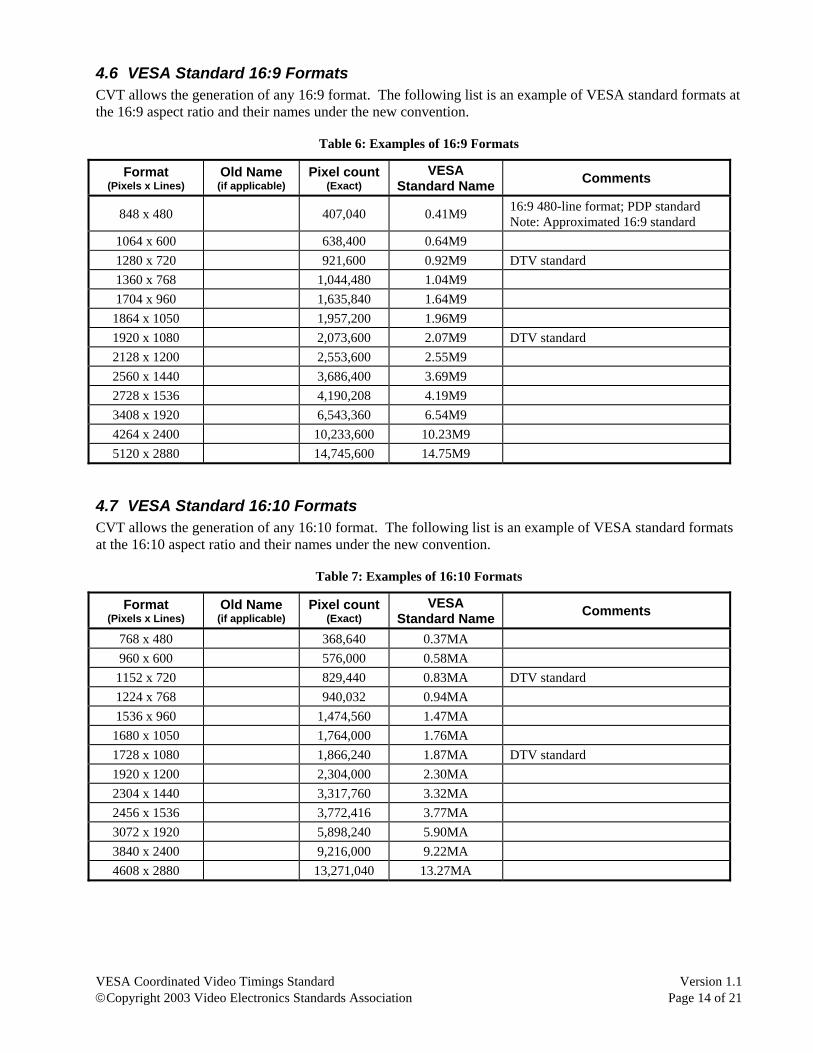
4.6 VESA Standard 16:9 Formats CVT allows the generation of any 16:9 format. The following list is an example of VESA standard formats at the 16:9 aspect ratio and their names under the new convention.
Table 6: Examples of 16:9 Formats
Format (Pixels x Lines)
Old Name (if applicable)
Pixel count(Exact)
VESA Standard Name Comments
848 x 480 407,040 0.41M9 16:9 480-line format; PDP standard Note: Approximated 16:9 standard
1064 x 600 638,400 0.64M9 1280 x 720 921,600 0.92M9 DTV standard 1360 x 768 1,044,480 1.04M9 1704 x 960 1,635,840 1.64M9
1864 x 1050 1,957,200 1.96M9 1920 x 1080 2,073,600 2.07M9 DTV standard 2128 x 1200 2,553,600 2.55M9 2560 x 1440 3,686,400 3.69M9 2728 x 1536 4,190,208 4.19M9 3408 x 1920 6,543,360 6.54M9 4264 x 2400 10,233,600 10.23M9 5120 x 2880 14,745,600 14.75M9
4.7 VESA Standard 16:10 Formats CVT allows the generation of any 16:10 format. The following list is an example of VESA standard formats at the 16:10 aspect ratio and their names under the new convention.
Table 7: Examples of 16:10 Formats
Format (Pixels x Lines)
Old Name (if applicable)
Pixel count(Exact)
VESA Standard Name Comments
768 x 480 368,640 0.37MA 960 x 600 576,000 0.58MA
1152 x 720 829,440 0.83MA DTV standard 1224 x 768 940,032 0.94MA 1536 x 960 1,474,560 1.47MA
1680 x 1050 1,764,000 1.76MA 1728 x 1080 1,866,240 1.87MA DTV standard 1920 x 1200 2,304,000 2.30MA 2304 x 1440 3,317,760 3.32MA 2456 x 1536 3,772,416 3.77MA 3072 x 1920 5,898,240 5.90MA 3840 x 2400 9,216,000 9.22MA 4608 x 2880 13,271,040 13.27MA
VESA Coordinated Video Timings Standard Version 1.1 ©Copyright 2003 Video Electronics Standards Association Page 15 of 21
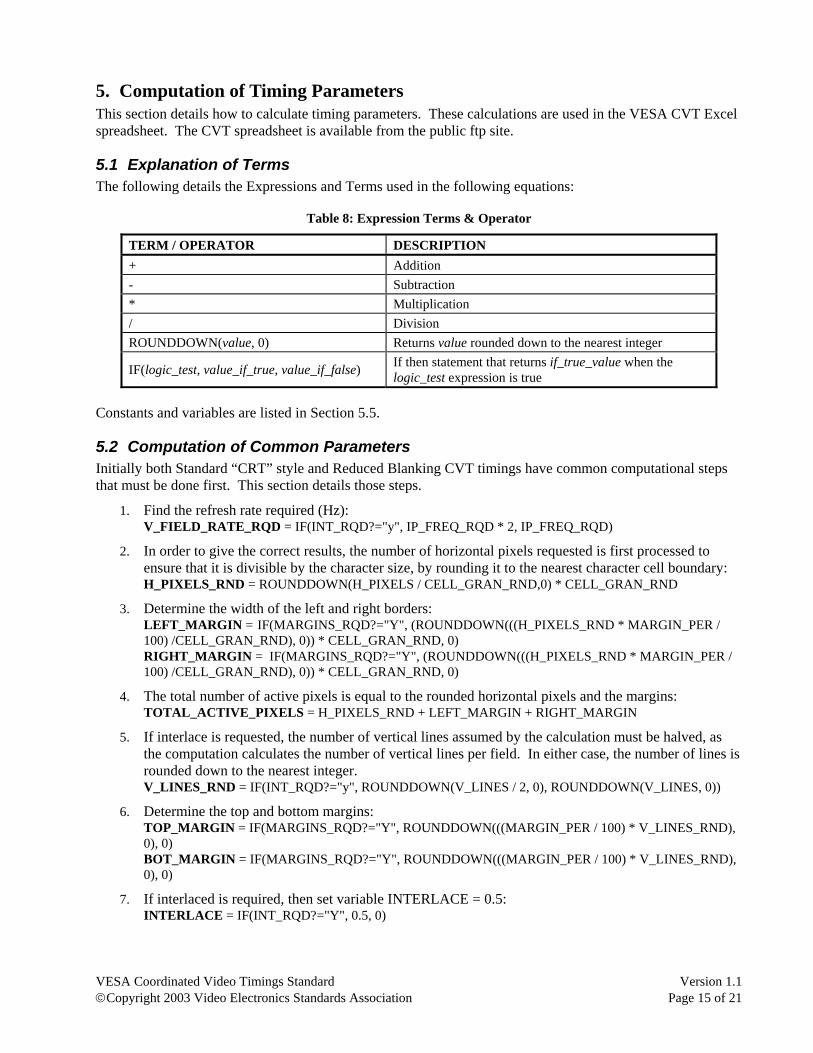
5. Computation of Timing Parameters This section details how to calculate timing parameters. These calculations are used in the VESA CVT Excel spreadsheet. The CVT spreadsheet is available from the public ftp site.
5.1 Explanation of Terms The following details the Expressions and Terms used in the following equations:
Table 8: Expression Terms & Operator
TERM / OPERATOR DESCRIPTION + Addition - Subtraction * Multiplication / Division ROUNDDOWN(value, 0) Returns value rounded down to the nearest integer
IF(logic_test, value_if_true, value_if_false) If then statement that returns if_true_value when the logic_test expression is true
Constants and variables are listed in Section 5.5.
5.2 Computation of Common Parameters Initially both Standard “CRT” style and Reduced Blanking CVT timings have common computational steps that must be done first. This section details those steps.
1. Find the refresh rate required (Hz): V_FIELD_RATE_RQD = IF(INT_RQD?="y", IP_FREQ_RQD * 2, IP_FREQ_RQD)
2. In order to give the correct results, the number of horizontal pixels requested is first processed to ensure that it is divisible by the character size, by rounding it to the nearest character cell boundary: H_PIXELS_RND = ROUNDDOWN(H_PIXELS / CELL_GRAN_RND,0) * CELL_GRAN_RND
3. Determine the width of the left and right borders: LEFT_MARGIN = IF(MARGINS_RQD?="Y", (ROUNDDOWN(((H_PIXELS_RND * MARGIN_PER / 100) /CELL_GRAN_RND), 0)) * CELL_GRAN_RND, 0) RIGHT_MARGIN = IF(MARGINS_RQD?="Y", (ROUNDDOWN(((H_PIXELS_RND * MARGIN_PER / 100) /CELL_GRAN_RND), 0)) * CELL_GRAN_RND, 0)
4. The total number of active pixels is equal to the rounded horizontal pixels and the margins: TOTAL_ACTIVE_PIXELS = H_PIXELS_RND + LEFT_MARGIN + RIGHT_MARGIN
5. If interlace is requested, the number of vertical lines assumed by the calculation must be halved, as the computation calculates the number of vertical lines per field. In either case, the number of lines is rounded down to the nearest integer. V_LINES_RND = IF(INT_RQD?="y", ROUNDDOWN(V_LINES / 2, 0), ROUNDDOWN(V_LINES, 0))
6. Determine the top and bottom margins: TOP_MARGIN = IF(MARGINS_RQD?="Y", ROUNDDOWN(((MARGIN_PER / 100) * V_LINES_RND), 0), 0) BOT_MARGIN = IF(MARGINS_RQD?="Y", ROUNDDOWN(((MARGIN_PER / 100) * V_LINES_RND), 0), 0)
7. If interlaced is required, then set variable INTERLACE = 0.5: INTERLACE = IF(INT_RQD?="Y", 0.5, 0)
VESA Coordinated Video Timings Standard Version 1.1 ©Copyright 2003 Video Electronics Standards Association Page 16 of 21
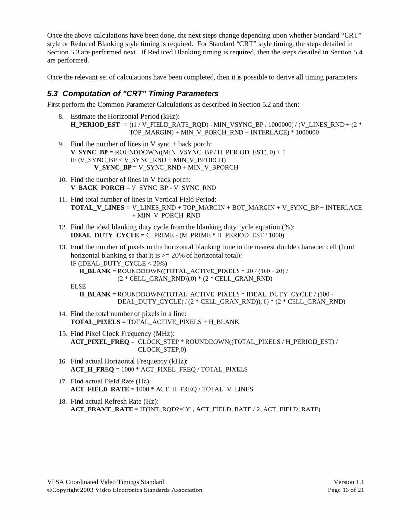
Once the above calculations have been done, the next steps change depending upon whether Standard “CRT” style or Reduced Blanking style timing is required. For Standard “CRT” style timing, the steps detailed in Section 5.3 are performed next. If Reduced Blanking timing is required, then the steps detailed in Section 5.4 are performed. Once the relevant set of calculations have been completed, then it is possible to derive all timing parameters.
5.3 Computation of "CRT" Timing Parameters First perform the Common Parameter Calculations as described in Section 5.2 and then:
8. Estimate the Horizontal Period (kHz): H_PERIOD_EST = ((1 / V_FIELD_RATE_RQD) - MIN_VSYNC_BP / 1000000) / (V_LINES_RND + (2 * TOP_MARGIN) + MIN_V_PORCH_RND + INTERLACE) * 1000000
9. Find the number of lines in V sync + back porch: V_SYNC_BP = ROUNDDOWN((MIN_VSYNC_BP / H_PERIOD_EST), 0) + 1 IF (V_SYNC_BP < V_SYNC_RND + MIN_V_BPORCH) V_SYNC_BP = V_SYNC_RND + MIN_V_BPORCH
10. Find the number of lines in V back porch: V_BACK_PORCH = V_SYNC_BP - V_SYNC_RND
11. Find total number of lines in Vertical Field Period: TOTAL_V_LINES = V_LINES_RND + TOP_MARGIN + BOT_MARGIN + V_SYNC_BP + INTERLACE + MIN_V_PORCH_RND
12. Find the ideal blanking duty cycle from the blanking duty cycle equation (%): IDEAL_DUTY_CYCLE = C_PRIME - (M_PRIME * H_PERIOD_EST / 1000)
13. Find the number of pixels in the horizontal blanking time to the nearest double character cell (limit horizontal blanking so that it is >= 20% of horizontal total): IF (IDEAL_DUTY_CYCLE < 20%) H_BLANK = ROUNDDOWN((TOTAL_ACTIVE_PIXELS * 20 / (100 - 20) / (2 * CELL_GRAN_RND)),0) * (2 * CELL_GRAN_RND) ELSE H_BLANK = ROUNDDOWN((TOTAL_ACTIVE_PIXELS * IDEAL_DUTY_CYCLE / (100 - DEAL_DUTY_CYCLE) / (2 * CELL_GRAN_RND)), 0) * (2 * CELL_GRAN_RND)
14. Find the total number of pixels in a line: TOTAL_PIXELS = TOTAL_ACTIVE_PIXELS + H_BLANK
15. Find Pixel Clock Frequency (MHz): ACT_PIXEL_FREQ = CLOCK_STEP * ROUNDDOWN((TOTAL_PIXELS / H_PERIOD_EST) / CLOCK_STEP,0)
16. Find actual Horizontal Frequency (kHz): ACT_H_FREQ = 1000 * ACT_PIXEL_FREQ / TOTAL_PIXELS
17. Find actual Field Rate (Hz): ACT_FIELD_RATE = 1000 * ACT_H_FREQ / TOTAL_V_LINES
18. Find actual Refresh Rate (Hz): ACT_FRAME_RATE = IF(INT_RQD?="Y", ACT_FIELD_RATE / 2, ACT_FIELD_RATE)

VESA Coordinated Video Timings Standard Version 1.1 ©Copyright 2003 Video Electronics Standards Association Page 17 of 21
5.4 Computation of Reduced Blanking Timing Parameters First perform the Common Parameter Calculations as described in Section 5.2 and then:
8. Estimate the Horizontal Period (kHz): H_PERIOD_EST = ((1000000 / V_FIELD_RATE_RQD) - RB_MIN_V_BLANK) / (V_LINES_RND + TOP_MARGIN + BOT_MARGIN)
9. Determine the number of lines in the vertical blanking interval: VBI_LINES = ROUNDDOWN(RB_MIN_V_BLANK / H_PERIOD_EST, 0) + 1
10. Check Vertical Blanking is Sufficient: RB_MIN_VBI = RB_V_FPORCH+V_SYNC_RND+MIN_V_BPORCH ACT_VBI_LINES = IF(VBI_LINES < RB_MIN_VBI, RB_MIN_VBI, VBI_LINES)
11. Find total number of vertical lines: TOTAL_V_LINES = ACT_VBI_LINES + V_LINES_RND + TOP_MARGIN + BOT_MARGIN + INTERLACE
12. Find total number of pixel clocks per line: TOTAL_PIXELS = RB_H_BLANK + TOTAL_ACTIVE_PIXELS
13. Calculate Pixel Clock Frequency to nearest 0.125 MHz: ACT_PIXEL_FREQ = CLOCK_STEP * ROUNDDOWN((V_FIELD_RATE_RQD * TOTAL_V_LINES * TOTAL_PIXELS / 1000000) / CLOCK_STEP,0)
14. Find actual Horizontal Frequency (kHz): ACT_H_FREQ = 1000 * ACT_PIXEL_FREQ / TOTAL_PIXELS
15. Find Actual Field Rate (Hz): ACT_FIELD_RATE = 1000*ACT_H_FREQ / TOTAL_V_LINES
16. Find actual Vertical Refresh Rate (Hz): ACT_FRAME_RATE = IF(INT_RQD? = "y", ACT_FIELD_RATE / 2, ACT_FIELD_RATE)
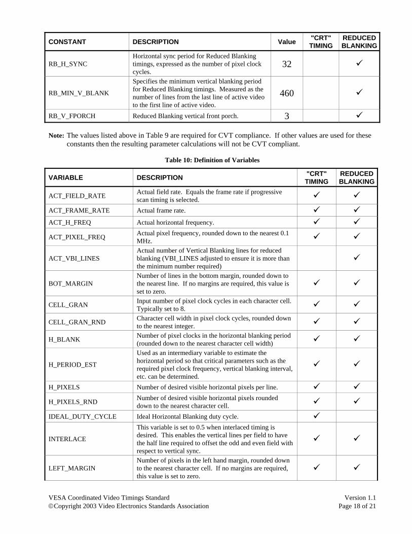
5.5 Definition of Constants & Variables
Table 9: Definition of Constants
CONSTANT DESCRIPTION Value "CRT" TIMING
REDUCED BLANKING
C_PRIME C_PRIME = ((C – J) * K / 256) + J 30
CLOCK_STEP Pixel clock resolution, see section 3.2. 0.25
H_SYNC_PER Percentage of the horizontal total period that defines horizontal sync width. 8%
M_PRIME M_PRIME = K / 256 * M 300
MIN_V_PORCH_RND Standard “CRT” Timing vertical front porch 3 MIN_VBPORCH Minimum vertical back porch. 6
MIN_VSYNC_BP Minimum time for Vertical Blanking period for "CRT" Timings. Set to 550us 550
RB_H_BLANK
Specifies the fixed number of pixel clock cycles in the Horizontal Blanking period for Reduced Blanking timings. Measured as the number of pixels from the last active pixel of one line to the first active pixel of the next line.
160
VESA Coordinated Video Timings Standard Version 1.1 ©Copyright 2003 Video Electronics Standards Association Page 18 of 21
CONSTANT DESCRIPTION Value "CRT" TIMING
REDUCED BLANKING
RB_H_SYNC Horizontal sync period for Reduced Blanking timings, expressed as the number of pixel clock cycles.
32
RB_MIN_V_BLANK
Specifies the minimum vertical blanking period for Reduced Blanking timings. Measured as the number of lines from the last line of active video to the first line of active video.
460
RB_V_FPORCH Reduced Blanking vertical front porch. 3 Note: The values listed above in Table 9 are required for CVT compliance. If other values are used for these
constants then the resulting parameter calculations will not be CVT compliant.
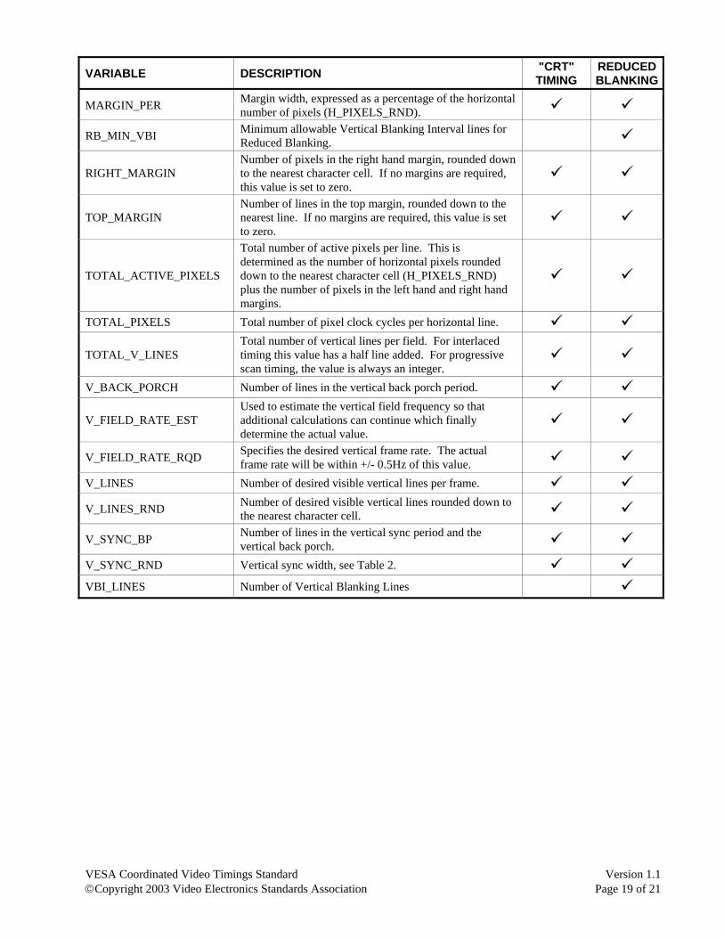
Table 10: Definition of Variables
VARIABLE DESCRIPTION "CRT" TIMING
REDUCED BLANKING
ACT_FIELD_RATE Actual field rate. Equals the frame rate if progressive scan timing is selected.
ACT_FRAME_RATE Actual frame rate.
ACT_H_FREQ Actual horizontal frequency.
ACT_PIXEL_FREQ Actual pixel frequency, rounded down to the nearest 0.1 MHz.
ACT_VBI_LINES Actual number of Vertical Blanking lines for reduced blanking (VBI_LINES adjusted to ensure it is more than the minimum number required)
BOT_MARGIN Number of lines in the bottom margin, rounded down to the nearest line. If no margins are required, this value is set to zero.
CELL_GRAN Input number of pixel clock cycles in each character cell. Typically set to 8.
CELL_GRAN_RND Character cell width in pixel clock cycles, rounded down to the nearest integer.
H_BLANK Number of pixel clocks in the horizontal blanking period (rounded down to the nearest character cell width)
H_PERIOD_EST
Used as an intermediary variable to estimate the horizontal period so that critical parameters such as the required pixel clock frequency, vertical blanking interval, etc. can be determined.
H_PIXELS Number of desired visible horizontal pixels per line.
H_PIXELS_RND Number of desired visible horizontal pixels rounded down to the nearest character cell.
IDEAL_DUTY_CYCLE Ideal Horizontal Blanking duty cycle.
INTERLACE
This variable is set to 0.5 when interlaced timing is desired. This enables the vertical lines per field to have the half line required to offset the odd and even field with respect to vertical sync.
LEFT_MARGIN Number of pixels in the left hand margin, rounded down to the nearest character cell. If no margins are required, this value is set to zero.
VESA Coordinated Video Timings Standard Version 1.1 ©Copyright 2003 Video Electronics Standards Association Page 19 of 21
VARIABLE DESCRIPTION "CRT" TIMING
REDUCED BLANKING
MARGIN_PER Margin width, expressed as a percentage of the horizontal number of pixels (H_PIXELS_RND).
RB_MIN_VBI Minimum allowable Vertical Blanking Interval lines for Reduced Blanking.
RIGHT_MARGIN Number of pixels in the right hand margin, rounded down to the nearest character cell. If no margins are required, this value is set to zero.
TOP_MARGIN Number of lines in the top margin, rounded down to the nearest line. If no margins are required, this value is set to zero.
TOTAL_ACTIVE_PIXELS
Total number of active pixels per line. This is determined as the number of horizontal pixels rounded down to the nearest character cell (H_PIXELS_RND) plus the number of pixels in the left hand and right hand margins.
TOTAL_PIXELS Total number of pixel clock cycles per horizontal line.
TOTAL_V_LINES Total number of vertical lines per field. For interlaced timing this value has a half line added. For progressive scan timing, the value is always an integer.
V_BACK_PORCH Number of lines in the vertical back porch period.
V_FIELD_RATE_EST Used to estimate the vertical field frequency so that additional calculations can continue which finally determine the actual value.
V_FIELD_RATE_RQD Specifies the desired vertical frame rate. The actual frame rate will be within +/- 0.5Hz of this value.
V_LINES Number of desired visible vertical lines per frame.
V_LINES_RND Number of desired visible vertical lines rounded down to the nearest character cell.
V_SYNC_BP Number of lines in the vertical sync period and the vertical back porch.
V_SYNC_RND Vertical sync width, see Table 2.
VBI_LINES Number of Vertical Blanking Lines
VESA Coordinated Video Timings Standard Version 1.1 ©Copyright 2003 Video Electronics Standards Association Page 20 of 21
The companion spreadsheet for the CVT Standard can be downloaded from the VESA website. Go to www.vesa.org and click on Free Standards and then Public FTP. The file is listed under CVT. Send an email to [email protected] if you have any problems accessing the file.
VESA Coordinated Video Timings Standard Version 1.1 ©Copyright 2003 Video Electronics Standards Association Page 21 of 21
PAGE INTENTIONALLY LEFT BLANK