Verification Analysis of the Slope Stability · 2016-05-16 · Verification Analysis of the Slope...
18
Verification Manual no. 3 Update 04/2016 1 Verification Analysis of the Slope Stability Program: Slope Stability File: Demo_vm_en_03.gst In this verification manual you will find hand-made verification analysis of the stability of slope and anchored slope in a permanent design situation. The results of the hand-made calculations are compared with the results from the GEO5 – Slope Stability program. Terms of Reference: In Figure 1, an example of a slope is shown. The slope has a height m H 0 . 10 and is adjusted in 1:1.5 inclination. At the top of the slope is a load 2 / 20 m kN f . The earth body is formed of sandy clay (CS). The properties of soil (effective values) are shown in Table 1. The calculation is divided into two stages. In the 1 st stage the stability of the slope is calculated and in the 2 nd stage the stability of an anchored slope is calculated. The slope stability is calculated using Fellenius/Petterson method and Bishop’s simplified method (the circular slip surface). The verification methodology of the slope stability is done according to safety factors. Figure 1 Slope - dimensions Soil Unit weight 3 / m kN Saturated unit weight 3 / m kN sat Angle of internal friction ef Cohesion of soil kPa c ef CS 18.50 19.50 27.00 21.00 Table 1 Soil properties – effective values
Transcript of Verification Analysis of the Slope Stability · 2016-05-16 · Verification Analysis of the Slope...

Verification Manual no. 3 Update 04/2016
1
Verification Analysis of the Slope Stability
Program: Slope Stability
File: Demo_vm_en_03.gst
In this verification manual you will find hand-made verification analysis of the stability of slope
and anchored slope in a permanent design situation. The results of the hand-made calculations are
compared with the results from the GEO5 – Slope Stability program.
Terms of Reference:
In Figure 1, an example of a slope is shown. The slope has a height mH 0.10 and is adjusted
in 1:1.5 inclination. At the top of the slope is a load 2/20 mkNf . The earth body is formed of sandy
clay (CS). The properties of soil (effective values) are shown in Table 1. The calculation is divided into
two stages. In the 1st stage the stability of the slope is calculated and in the 2nd stage the stability of an
anchored slope is calculated. The slope stability is calculated using Fellenius/Petterson method and
Bishop’s simplified method (the circular slip surface). The verification methodology of the slope
stability is done according to safety factors.
Figure 1 Slope - dimensions
Soil Unit weight
3/ mkN
Saturated unit weight
3/ mkNsat
Angle of internal friction
ef
Cohesion of soil
kPacef
CS 18.50 19.50 27.00 21.00
Table 1 Soil properties – effective values
2
1. Fellenius/Petterson Method
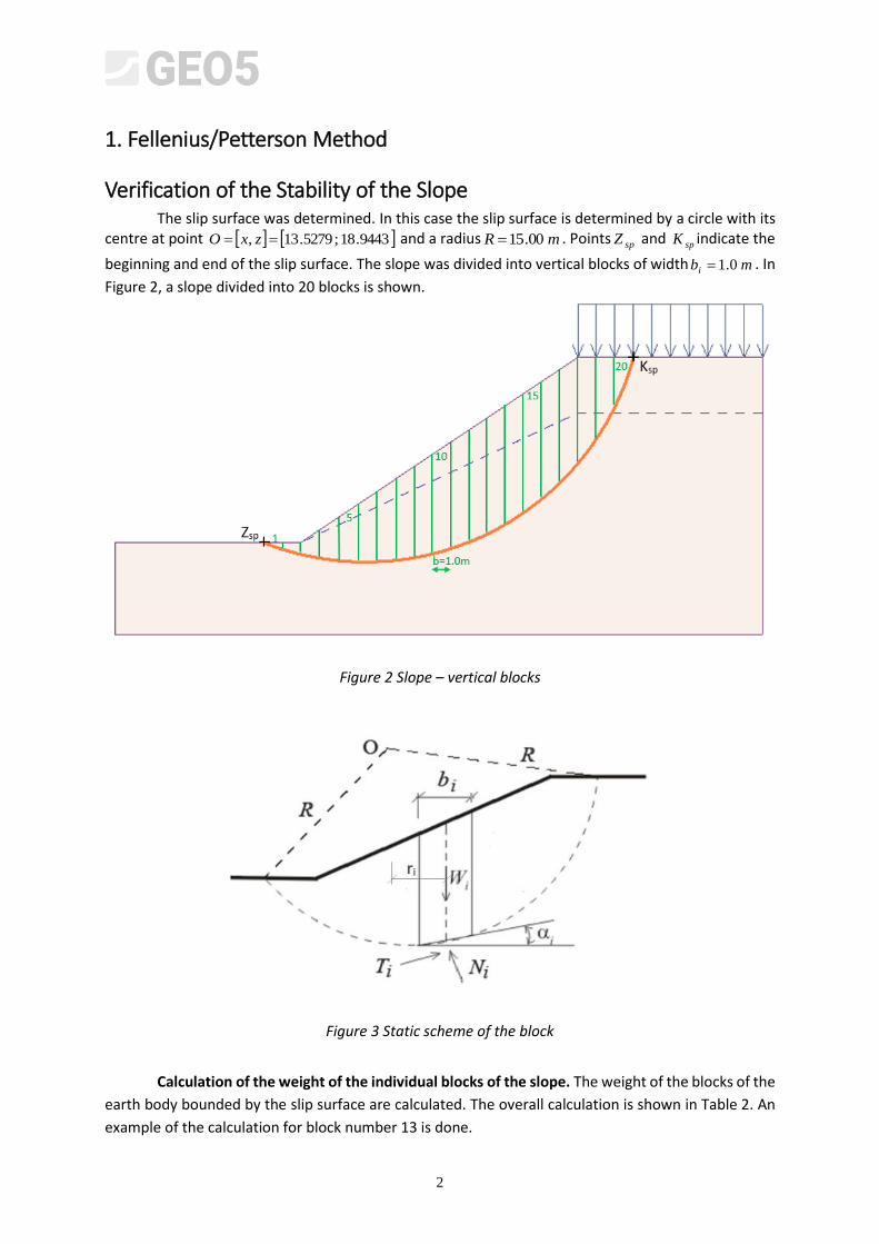
Verification of the Stability of the Slope The slip surface was determined. In this case the slip surface is determined by a circle with its centre at point 9443.18;5279.13, zxO and a radius mR 00.15 . Points spZ and spK indicate the
beginning and end of the slip surface. The slope was divided into vertical blocks of width mbi 0.1 . In
Figure 2, a slope divided into 20 blocks is shown.
Figure 2 Slope – vertical blocks
Figure 3 Static scheme of the block
Calculation of the weight of the individual blocks of the slope. The weight of the blocks of the
earth body bounded by the slip surface are calculated. The overall calculation is shown in Table 2. An
example of the calculation for block number 13 is done.
3
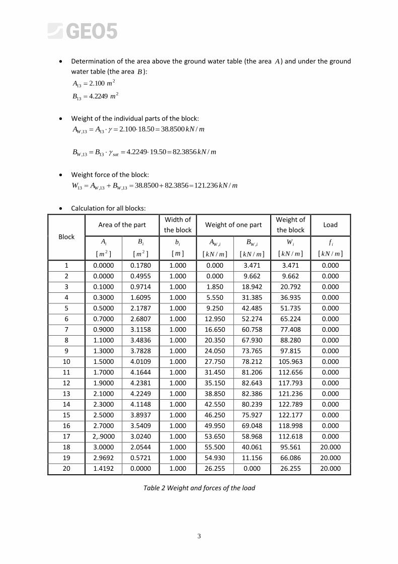
Determination of the area above the ground water table (the area A ) and under the ground
water table (the area B ): 2
13 100.2 mA
213 2249.4 mB
Weight of the individual parts of the block:
mkNAAW /8500.3850.18100.21313,
mkNBB satW /3856.8250.192249.41313,
Weight force of the block:
mkNBAW WW /236.1213856.828500.3813,13,13
Calculation for all blocks:
Block
Area of the part Width of
the block Weight of one part
Weight of
the block Load
iA
[ 2m ]
iB
[ 2m ]
ib
[ m ]
iWA ,
[ mkN / ]
iWB ,
[ mkN / ]
iW
[ mkN / ]
if
[ mkN / ]
1 0.0000 0.1780 1.000 0.000 3.471 3.471 0.000
2 0.0000 0.4955 1.000 0.000 9.662 9.662 0.000
3 0.1000 0.9714 1.000 1.850 18.942 20.792 0.000
4 0.3000 1.6095 1.000 5.550 31.385 36.935 0.000
5 0.5000 2.1787 1.000 9.250 42.485 51.735 0.000
6 0.7000 2.6807 1.000 12.950 52.274 65.224 0.000
7 0.9000 3.1158 1.000 16.650 60.758 77.408 0.000
8 1.1000 3.4836 1.000 20.350 67.930 88.280 0.000
9 1.3000 3.7828 1.000 24.050 73.765 97.815 0.000
10 1.5000 4.0109 1.000 27.750 78.212 105.963 0.000
11 1.7000 4.1644 1.000 31.450 81.206 112.656 0.000
12 1.9000 4.2381 1.000 35.150 82.643 117.793 0.000
13 2.1000 4.2249 1.000 38.850 82.386 121.236 0.000
14 2.3000 4.1148 1.000 42.550 80.239 122.789 0.000
15 2.5000 3.8937 1.000 46.250 75.927 122.177 0.000
16 2.7000 3.5409 1.000 49.950 69.048 118.998 0.000
17 2,.9000 3.0240 1.000 53.650 58.968 112.618 0.000
18 3.0000 2.0544 1.000 55.500 40.061 95.561 20.000
19 2.9692 0.5721 1.000 54.930 11.156 66.086 20.000
20 1.4192 0.0000 1.000 26.255 0.000 26.255 20.000
Table 2 Weight and forces of the load
4
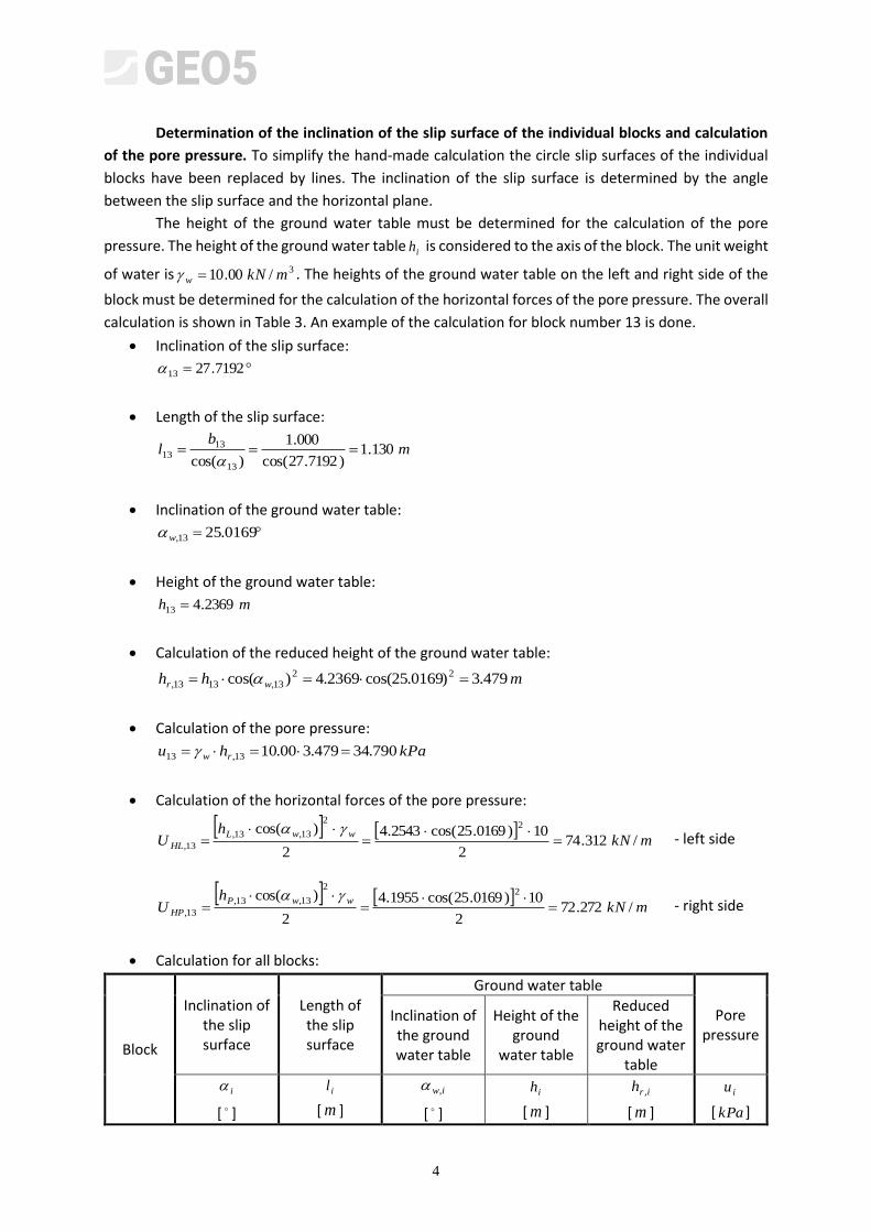
Determination of the inclination of the slip surface of the individual blocks and calculation
of the pore pressure. To simplify the hand-made calculation the circle slip surfaces of the individual
blocks have been replaced by lines. The inclination of the slip surface is determined by the angle
between the slip surface and the horizontal plane.
The height of the ground water table must be determined for the calculation of the pore
pressure. The height of the ground water table ih is considered to the axis of the block. The unit weight
of water is 3/00.10 mkNw . The heights of the ground water table on the left and right side of the
block must be determined for the calculation of the horizontal forces of the pore pressure. The overall
calculation is shown in Table 3. An example of the calculation for block number 13 is done.
Inclination of the slip surface:
7192.2713
Length of the slip surface:
mb
l 130.1)7192.27cos(
000.1
)cos( 13
1313
Inclination of the ground water table:
0169.2513,w
Height of the ground water table:
mh 2369.413
Calculation of the reduced height of the ground water table:
mhh wr 479.3)0169.25cos(2369.4)cos( 2213,1313,
Calculation of the pore pressure:
kPahu rw 790.34479.300.1013,13
Calculation of the horizontal forces of the pore pressure:
mkN
hU
wwL
HL /312.742
10)0169.25cos(2543.4
2
)cos( 22
13,13,
13,
- left side
mkN
hU
wwP
HP /272.722
10)0169.25cos(1955.4
2
)cos( 22
13,13,
13,
- right side
Calculation for all blocks:
Block
Inclination of the slip surface
Length of the slip surface
Ground water table
Pore pressure
Inclination of the ground water table
Height of the ground
water table
Reduced height of the ground water
table
i
[ ]
il
[ m ]
iw,
[ ]
ih
[ m ]
irh ,
[ m ]
iu
[ kPa ]
5
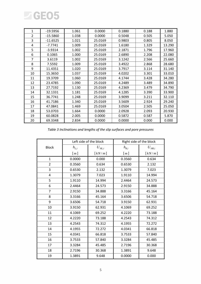
1 -19.5956 1.061 0.0000 0.1880 0.188 1.880
2 -15.5860 1.038 0.0000 0.5048 0.505 5.050
3 -11.6525 1.021 25.0169 0.9803 0.805 8.050
4 -7.7741 1.009 25.0169 1.6180 1.329 13.290
5 -3.9314 1.002 25.0169 2.1871 1.796 17.960
6 0.1065 1.000 25.0169 2.6890 2.208 22.080
7 3.6119 1.002 25.0169 3.1242 2.566 25.660
8 7.5592 1.009 25.0169 3.4922 2.868 28.680
9 11.4351 1.020 25.0169 3.7917 3.114 31.140
10 15.3650 1.037 25.0169 4.0202 3.301 33.010
11 19.3709 1.060 25.0169 4.1744 3.428 34.280
12 23.4785 1.090 25.0169 4.2489 3.489 34.890
13 27.7192 1.130 25.0169 4.2369 3.479 34.790
14 32.1331 1.181 25.0169 4.1285 3.390 33.900
15 36.7741 1.248 25.0169 3.9099 3.211 32.110
16 41.7186 1.340 25.0169 3.5609 2.924 29.240
17 47.0841 1.469 25.0169 3.0504 2.505 25.050
18 53.0703 1.664 0.0000 2.0928 2.093 20.930
19 60.0828 2.005 0.0000 0.5872 0.587 5.870
20 69.3348 2.834 0.0000 0.0000 0.000 0.000
Table 3 Inclinations and lengths of the slip surfaces and pore pressures
Block
Left side of the block Right side of the block
iLh ,
[ m ]
iHLU ,
[ mkN / ]
iRh ,
[ m ]
iHRU ,
[ mkN / ]
1 0.0000 0.000 0.3560 0.634
2 0.3560 0.634 0.6530 2.132
3 0.6530 2.132 1.3079 7.023
4 1.3079 7.023 1.9110 14.994
5 1.9110 14.994 2.4464 24.573
6 2.4464 24.573 2.9150 34.888
7 2.9150 34.888 3.3166 45.164
8 3.3166 45.164 3.6506 54.718
9 3.6506 54.718 3.9150 62.931
10 3.9150 62.931 4.1069 69.252
11 4.1069 69.252 4.2220 73.188
12 4.2220 73.188 4.2543 74.312
13 4.2543 74.312 4.1955 72.272
14 4.1955 72.272 4.0341 66.818
15 4.0341 66.818 3.7533 57.840
16 3.7533 57.840 3.3284 45.485
17 3.3284 45.485 2.7196 30.368
18 2.7196 30.368 1.3891 9.648
19 1.3891 9.648 0.0000 0.000
6
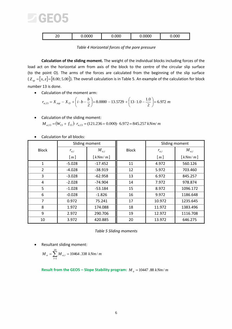
20 0.0000 0.000 0.0000 0.000
Table 4 Horizontal forces of the pore pressure
Calculation of the sliding moment. The weight of the individual blocks including forces of the
load act on the horizontal arm from axis of the block to the centre of the circular slip surface
(to the point O). The arms of the forces are calculated from the beginning of the slip surface
( 00.5;00.8, zxZ sp ). The overall calculation is in Table 5. An example of the calculation for block
number 13 is done.
Calculation of the moment arm:
mb
biXXr Ozspa 972.62
0.10.1135729.130000.8
213,
Calculation of the sliding moment:
mkNmrfWM aa /257.845972.6)000.0236.121(13,131313,
Calculation for all blocks:
Block
Sliding moment
Block
Sliding moment
iar ,
[ m ]
iaM ,
[ mkNm / ]
iar ,
[ m ]
iaM ,
[ mkNm / ]
1 -5.028 -17.452 11 4.972 560.126
2 -4.028 -38.919 12 5.972 703.460
3 -3.028 -62.958 13 6.972 845.257
4 -2.028 -74.904 14 7.972 978.874
5 -1.028 -53.184 15 8.972 1096.172
6 -0.028 -1.826 16 9.972 1186.648
7 0.972 75.241 17 10.972 1235.645
8 1.972 174.088 18 11.972 1383.496
9 2.972 290.706 19 12.972 1116.708
10 3.972 420.885 20 13.972 646.275
Table 5 Sliding moments
Resultant sliding moment:
20
1
, /338.10464i
iaa mkNmMM
Result from the GEO5 – Slope Stability program: mkNmM a /88.10447
7
Resultant active force:
mkNR
M
F i
ia
a /623.69700.15
338.10464
20
1
,
Result from the GEO5 – Slope Stability program: mkNFa /53.696
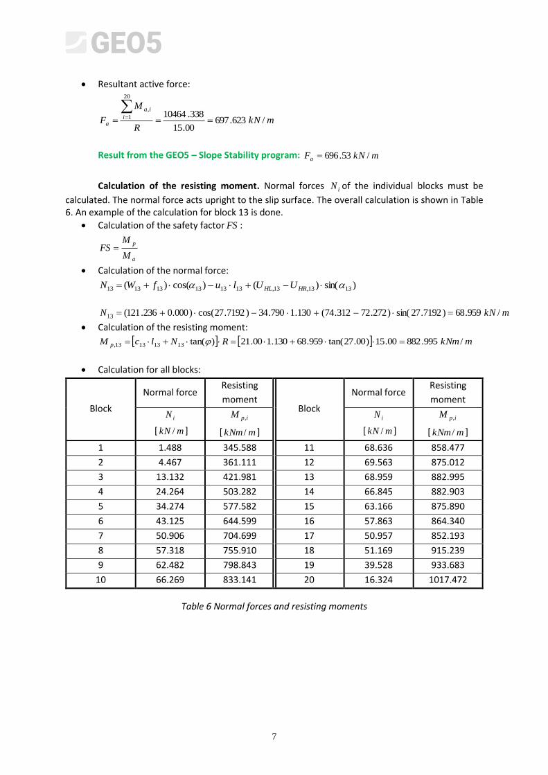
Calculation of the resisting moment. Normal forces iN of the individual blocks must be
calculated. The normal force acts upright to the slip surface. The overall calculation is shown in Table 6. An example of the calculation for block 13 is done.
Calculation of the safety factor FS :
a
p
M
MFS
Calculation of the normal force:
)sin()()cos()( 1313,13,131313131313 HRHL UUlufWN
mkNN /959.68)7192.27sin()272.72312.74(130.1790.34)7192.27cos()000.0236.121(13
Calculation of the resisting moment:
mkNmRNlcM p /995.88200.15)00.27tan(959.68130.100.21)tan(13131313,
Calculation for all blocks:
Block
Normal force Resisting
moment Block
Normal force Resisting
moment
iN
[ mkN / ]
ipM ,
[ mkNm / ]
iN
[ mkN / ]
ipM ,
[ mkNm / ]
1 1.488 345.588 11 68.636 858.477
2 4.467 361.111 12 69.563 875.012
3 13.132 421.981 13 68.959 882.995
4 24.264 503.282 14 66.845 882.903
5 34.274 577.582 15 63.166 875.890
6 43.125 644.599 16 57.863 864.340
7 50.906 704.699 17 50.957 852.193
8 57.318 755.910 18 51.169 915.239
9 62.482 798.843 19 39.528 933.683
10 66.269 833.141 20 16.324 1017.472
Table 6 Normal forces and resisting moments
8
Resultant resisting moment:
mkNmMMi
ipp /940.1490420
1
,
Result from the GEO5 – Slope Stability program: mkNmM p /16.14936
Resultant passive force:
mkNR
M
F i
ip
p /663.99300.15
940.14904
20
1
,
Result from the GEO5 – Slope Stability program: mkNFp /74.995
Calculation of the safety factor:
424.1338.10464
940.14904
a
p
M
MFS , NOT OK
Result from the GEO5 – Slope Stability program: 43.1FS , NOT OK
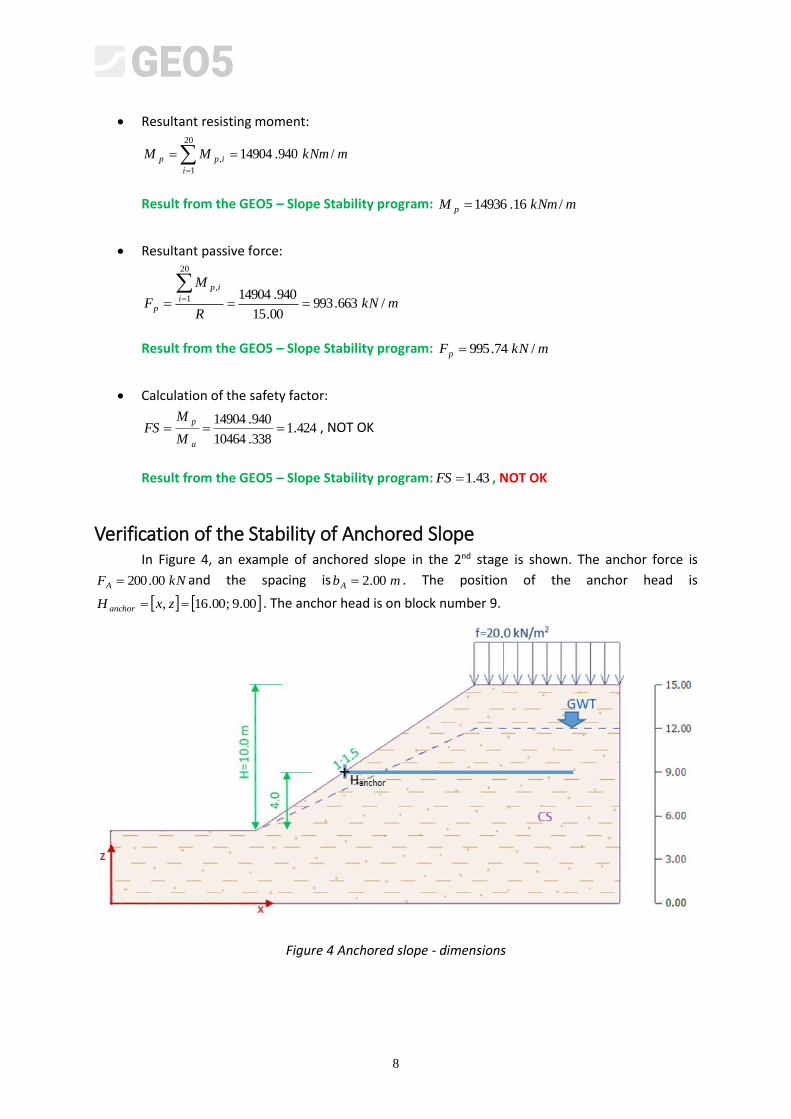
Verification of the Stability of Anchored Slope In Figure 4, an example of anchored slope in the 2nd stage is shown. The anchor force is
kNFA 00.200 and the spacing is mbA 00.2 . The position of the anchor head is
00.9;00.16, zxH anchor . The anchor head is on block number 9.
Figure 4 Anchored slope - dimensions
9
Calculation of the sliding moment. The anchor acts as a passive element, which means that active moments will be the same as in the 1st stage.
Resultant sliding moment:
20
1
, /338.10464i
iaa mkNmMM
Result from the GEO5 – Slope Stability program: mkNmM a /88.10447
Resultant active force:
mkNR
M
F i
ia
a /623.69700.15
338.10464
20
1
,
Result from the GEO5 – Slope Stability program: mkNFa /53.696
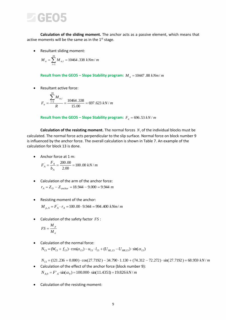
Calculation of the resisting moment. The normal forces iN of the individual blocks must be
calculated. The normal force acts perpendicular to the slip surface. Normal force on block number 9 is influenced by the anchor force. The overall calculation is shown in Table 7. An example of the calculation for block 13 is done.
Anchor force at 1 m:
mkNb
FF
A
AA /00.100
00.2
00.200'
Calculation of the arm of the anchor force:
mZZr anchorOA 944.9000.9944.18
Resisting moment of the anchor:
mkNmrFM AAAp /400.994944.900.100',
Calculation of the safety factor FS :
a
p
M
MFS
Calculation of the normal force:
)sin()()cos()( 1313,13,131313131313 HRHL UUlufWN
mkNN /959.68)7192.27sin()272.72312.74(130.1790.34)7192.27cos()000.0236.121(13
Calculation of the effect of the anchor force (block number 9):
mkNFN AA /826.19)4351.11sin(000.100)sin(' 99,
Calculation of the resisting moment:
10
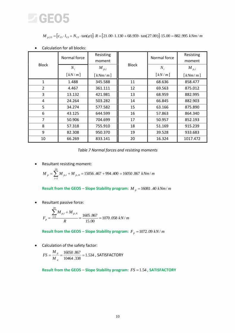
mkNmRNlcM p /995.88200.15)00.27tan(959.68130.100.21)tan(13131313,
Calculation for all blocks:
Block
Normal force Resisting
moment Block
Normal force Resisting
moment
iN
[ mkN / ]
ipM ,
[ mkNm / ]
iN
[ mkN / ]
ipM ,
[ mkNm / ]
1 1.488 345.588 11 68.636 858.477
2 4.467 361.111 12 69.563 875.012
3 13.132 421.981 13 68.959 882.995
4 24.264 503.282 14 66.845 882.903
5 34.274 577.582 15 63.166 875.890
6 43.125 644.599 16 57.863 864.340
7 50.906 704.699 17 50.957 852.193
8 57.318 755.910 18 51.169 915.239
9 82.308 950.370 19 39.528 933.683
10 66.269 833.141 20 16.324 1017.472
Table 7 Normal forces and resisting moments
Resultant resisting moment:
mkNmMMM Ap
i
ipp /867.16050400.994467.15056,
20
1
,
Result from the GEO5 – Slope Stability program: mkNmM p /40.16081
Resultant passive force:
mkNR
MM
F i
Apip
p /058.107000.15
867.1605
20
1
,,
Result from the GEO5 – Slope Stability program: mkNFp /09.1072
Calculation of the safety factor:
534.1338.10464
867.16050
a
p
M
MFS , SATISFACTORY
Result from the GEO5 – Slope Stability program: 54.1FS , SATISFACTORY
12
2. Bishop’s Simplified Method
Verification of the Stability of the Slope
The slip surface is the same as in the first calculation using the Fellenius/Petterson method (Figure 2). The calculation of the weight of the individual blocks is shown in Table 2.
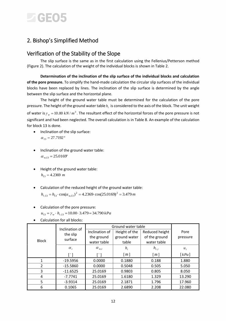
Determination of the inclination of the slip surface of the individual blocks and calculation
of the pore pressure. To simplify the hand-made calculation the circular slip surfaces of the individual
blocks have been replaced by lines. The inclination of the slip surface is determined by the angle
between the slip surface and the horizontal plane.
The height of the ground water table must be determined for the calculation of the pore
pressure. The height of the ground water table ih is considered to the axis of the block. The unit weight
of water is 3/00.10 mkNw . The resultant effect of the horizontal forces of the pore pressure is not
significant and had been neglected. The overall calculation is in Table 8. An example of the calculation
for block 13 is done.
Inclination of the slip surface:
7192.2713
Inclination of the ground water table:
0169.2513,w
Height of the ground water table:
mh 2369.413
Calculation of the reduced height of the ground water table:
mhh wr 479.3)0169.25cos(2369.4)cos( 2213,1313,
Calculation of the pore pressure:
kPahu rw 790.34479.300.1013,13
Calculation for all blocks:
Block
Inclination of the slip surface
Ground water table Pore
pressure Inclination of the ground water table
Height of the ground water
table
Reduced height of the ground water table
i
[ ]
iw,
[ ]
ih
[ m ]
irh ,
[ m ]
iu
[ kPa ]
1 -19.5956 0.0000 0.1880 0.188 1.880
2 -15.5860 0.0000 0.5048 0.505 5.050
3 -11.6525 25.0169 0.9803 0.805 8.050
4 -7.7741 25.0169 1.6180 1.329 13.290
5 -3.9314 25.0169 2.1871 1.796 17.960
6 0.1065 25.0169 2.6890 2.208 22.080
12
7 3.6119 25.0169 3.1242 2.565 25.650
8 7.5592 25.0169 3.4922 2.868 28.680
9 11.4351 25.0169 3.7917 3.114 31.140
10 15.3650 25.0169 4.0202 3.301 33.010
11 19.3709 25.0169 4.1744 3.428 34.280
12 23.4785 25.0169 4.2489 3.489 34.890
13 27.7192 25.0169 4.2369 3.479 34.790
14 32.1331 25.0169 4.1285 3.390 33.900
15 36.7741 25.0169 3.9099 3.211 32.110
16 41.7186 25.0169 3.5609 2.924 29.240
17 47.0841 25.0169 3.0504 2.505 25.050
18 53.0703 0.0000 2.0928 2.093 20.930
19 60.0828 0.0000 0.5872 0.587 5.870
20 69.3348 0.0000 0.0000 0.000 0.000
Table 8 Inclinations of the slip surfaces and pore pressures
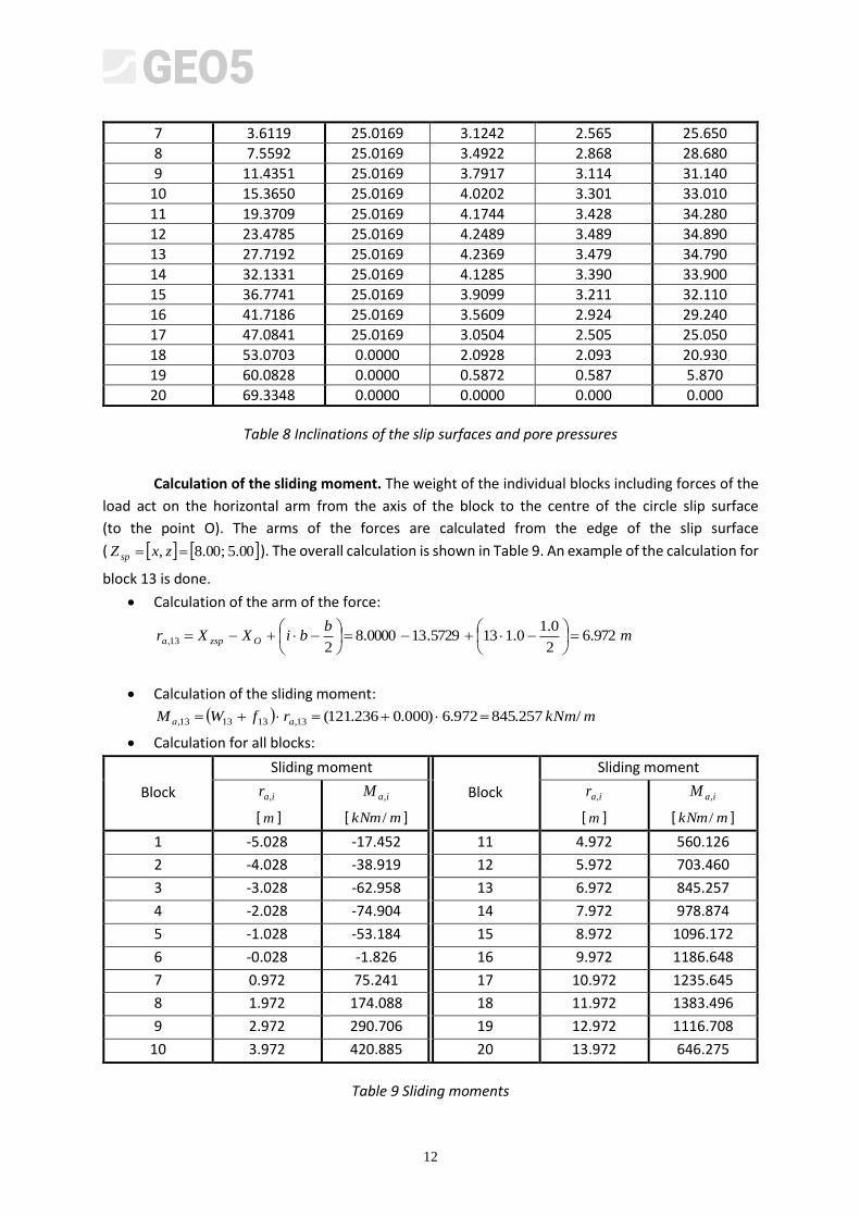
Calculation of the sliding moment. The weight of the individual blocks including forces of the
load act on the horizontal arm from the axis of the block to the centre of the circle slip surface
(to the point O). The arms of the forces are calculated from the edge of the slip surface
( 00.5;00.8, zxZ sp ). The overall calculation is shown in Table 9. An example of the calculation for
block 13 is done.
Calculation of the arm of the force:
mb
biXXr Ozspa 972.62
0.10.1135729.130000.8
213,
Calculation of the sliding moment:
mkNmrfWM aa /257.845972.6)000.0236.121(13,131313,
Calculation for all blocks:
Block
Sliding moment
Block
Sliding moment
iar ,
[ m ]
iaM ,
[ mkNm / ]
iar ,
[ m ]
iaM ,
[ mkNm / ]
1 -5.028 -17.452 11 4.972 560.126
2 -4.028 -38.919 12 5.972 703.460
3 -3.028 -62.958 13 6.972 845.257
4 -2.028 -74.904 14 7.972 978.874
5 -1.028 -53.184 15 8.972 1096.172
6 -0.028 -1.826 16 9.972 1186.648
7 0.972 75.241 17 10.972 1235.645
8 1.972 174.088 18 11.972 1383.496
9 2.972 290.706 19 12.972 1116.708
10 3.972 420.885 20 13.972 646.275
Table 9 Sliding moments
13
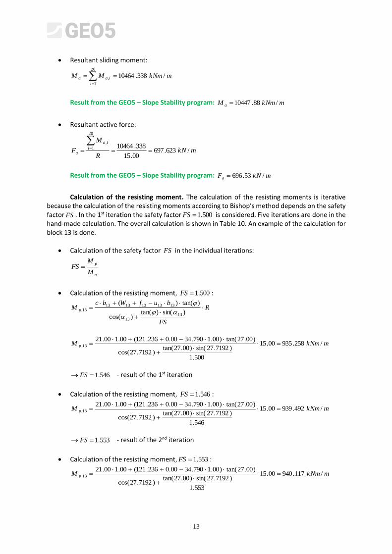
Resultant sliding moment:
20
1
, /338.10464i
iaa mkNmMM
Result from the GEO5 – Slope Stability program: mkNmM a /88.10447
Resultant active force:
mkNR
M
F i
ia
a /623.69700.15
338.10464
20
1
,
Result from the GEO5 – Slope Stability program: mkNFa /53.696
Calculation of the resisting moment. The calculation of the resisting moments is iterative because the calculation of the resisting moments according to Bishop’s method depends on the safety factor FS . In the 1st iteration the safety factor 500.1FS is considered. Five iterations are done in the hand-made calculation. The overall calculation is shown in Table 10. An example of the calculation for block 13 is done.
Calculation of the safety factor FS in the individual iterations:
a
p
M
MFS
Calculation of the resisting moment, 500.1FS :
R
FS
bufWbcM p
)sin()tan()cos(
)tan()(
1313
131313131313,
mkNmM p /258.93500.15
500.1
)7192.27sin()00.27tan()7192.27cos(
)00.27tan()00.1790.3400.0236.121(00.100.2113,
546.1 FS - result of the 1st iteration
Calculation of the resisting moment, 546.1FS :
mkNmM p /492.93900.15
546.1
)7192.27sin()00.27tan()7192.27cos(
)00.27tan()00.1790.3400.0236.121(00.100.2113,
553.1 FS - result of the 2nd iteration
Calculation of the resisting moment, 553.1FS :
mkNmM p /117.94000.15
553.1
)7192.27sin()00.27tan()7192.27cos(
)00.27tan()00.1790.3400.0236.121(00.100.2113,
14
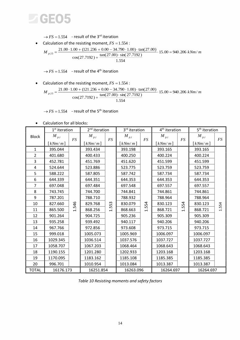
554.1 FS - result of the 3rd iteration
Calculation of the resisting moment, 554.1FS :
mkNmM p /206.94000.15
554.1
)7192.27sin()00.27tan()7192.27cos(
)00.27tan()00.1790.3400.0236.121(00.100.2113,
554.1 FS - result of the 4th iteration
Calculation of the resisting moment, 554.1FS :
mkNmM p /206.94000.15
554.1
)7192.27sin()00.27tan()7192.27cos(
)00.27tan()00.1790.3400.0236.121(00.100.2113,
554.1 FS - result of the 5th iteration
Calculation for all blocks:
Block
1st iteration 2nd iteration 3rd iteration 4th iteration 5th iteration
ipM ,
[ mkNm/ ] FS
ipM ,
[ mkNm/ ] FS
ipM ,
[ mkNm/ ] FS
ipM ,
[ mkNm/ ] FS
ipM ,
[ mkNm/ ] FS
1 395.044
1.5
46
393.434
1.5
53
393.198 1
.55
4
393.165
1.5
54
393.165
1.5
54
2 401.680 400.433 400.250 400.224 400.224
3 452.781 451.769 451.620 451.599 451.599
4 524.644 523.886 523.775 523.759 523.759
5 588.222 587.805 587.742 587.734 587.734
6 644.339 644.351 644.353 644.353 644.353
7 697.048 697.484 697.548 697.557 697.557
8 743.745 744.700 744.841 744.861 744.861
9 787.201 788.710 788.932 788.964 788.964
10 827.660 829.768 830.079 830.123 830.123
11 865.500 868.256 868.663 868.721 868.721
12 901.264 904.725 905.236 905.309 905.309
13 935.258 939.492 940.117 940.206 940.206
14 967.766 972.856 973.608 973.715 973.715
15 999.018 1005.073 1005.969 1006.097 1006.097
16 1029.345 1036.514 1037.576 1037.727 1037.727
17 1058.707 1067.203 1068.464 1068.643 1068.643
18 1190.155 1201.280 1202.933 1203.168 1203.168
19 1170.095 1183.162 1185.108 1185.385 1185.385
20 996.701 1010.954 1013.084 1013.387 1013.387
TOTAL 16176.173 16251.854 16263.096 16264.697 16264.697
Table 10 Resisting moments and safety factors
15
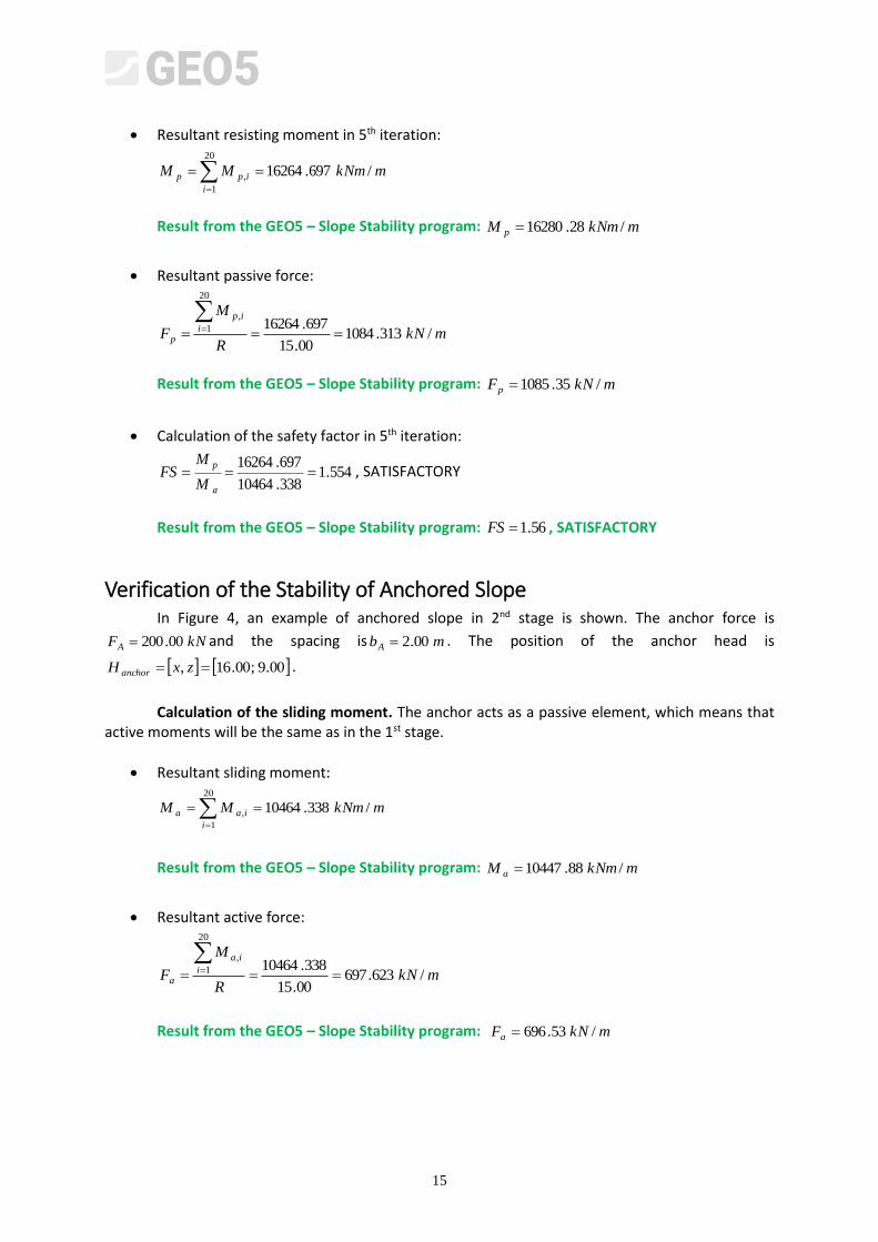
Resultant resisting moment in 5th iteration:
mkNmMMi
ipp /697.1626420
1
,
Result from the GEO5 – Slope Stability program: mkNmM p /28.16280
Resultant passive force:
mkNR
M
F i
ip
p /313.108400.15
697.16264
20
1
,
Result from the GEO5 – Slope Stability program: mkNFp /35.1085
Calculation of the safety factor in 5th iteration:
554.1338.10464
697.16264
a
p
M
MFS , SATISFACTORY
Result from the GEO5 – Slope Stability program: 56.1FS , SATISFACTORY
Verification of the Stability of Anchored Slope In Figure 4, an example of anchored slope in 2nd stage is shown. The anchor force is
kNFA 00.200 and the spacing is mbA 00.2 . The position of the anchor head is
00.9;00.16, zxH anchor .
Calculation of the sliding moment. The anchor acts as a passive element, which means that
active moments will be the same as in the 1st stage.
Resultant sliding moment:
20
1
, /338.10464i
iaa mkNmMM
Result from the GEO5 – Slope Stability program: mkNmM a /88.10447
Resultant active force:
mkNR
M
F i
ia
a /623.69700.15
338.10464
20
1
,
Result from the GEO5 – Slope Stability program: mkNFa /53.696

16
Calculation of the resisting moment. The anchor force enters the calculation of the resisting moments. The calculation of the resisting moments is iterative because the calculation of the resisting moments using the Bishop’s method depends on the safety factor FS . In the 1st iteration the safety factor is 500.1FS . Five iterations are done in the hand-made calculation. The overall calculation is shown in Table 11. An example of the calculation for block 13 is done.
Anchor force at 1 m:
mkNb
FF
A
AA /00.100
00.2
00.200'
Calculation of the arm of the anchor force:
mZZr anchorOA 944.9000.9944.18
Resisting moment of the anchor:
mkNmrFM AAAp /400.994944.900.100',
Calculation of the safety factor FS in the individual iterations:
a
p
M
MFS
Calculation of the resisting moment, 500.1FS :
R
FS
bufWbcM p
)sin()tan()cos(
)tan()(
1313
131313131313,
mkNmM p /258.93500.15
500.1
)7192.27sin()00.27tan()7192.27cos(
)00.27tan()00,1790.3400.0236.121(00.100.2113,
641.1 FS - result of the 1st iteration
Calculation of the resisting moment, 641.1FS :
mkNmM p /589.94700.15
641.1
)7192.27sin()00.27tan()7192.27cos(
)00.27tan()00.1790.3400.0236.121(00.100.2113,
662.1 FS - result of the 2nd iteration
Calculation of the resisting moment, 662.1FS :
mkNmM p /272.94900.15
662.1
)7192.27sin()00.27tan()7192.27cos(
)00.27tan()00.1790.3400.0236.121(00.100.2113,
665.1 FS - result of the 3rd iteration
17
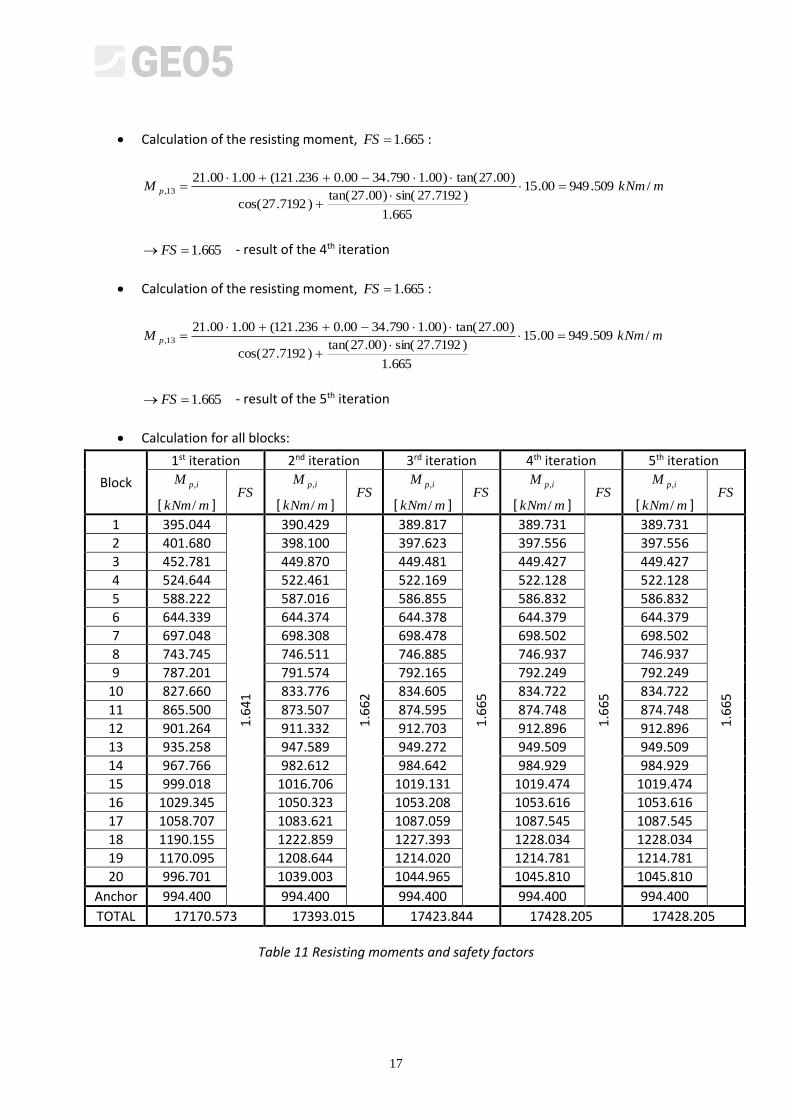
Calculation of the resisting moment, 665.1FS :
mkNmM p /509.94900.15
665.1
)7192.27sin()00.27tan()7192.27cos(
)00.27tan()00.1790.3400.0236.121(00.100.2113,
665.1 FS - result of the 4th iteration
Calculation of the resisting moment, 665.1FS :
mkNmM p /509.94900.15
665.1
)7192.27sin()00.27tan()7192.27cos(
)00.27tan()00.1790.3400.0236.121(00.100.2113,
665.1 FS - result of the 5th iteration
Calculation for all blocks:
Block
1st iteration 2nd iteration 3rd iteration 4th iteration 5th iteration
ipM ,
[ mkNm/ ] FS
ipM ,
[ mkNm/ ] FS
ipM ,
[ mkNm/ ] FS
ipM ,
[ mkNm/ ] FS
ipM ,
[ mkNm/ ] FS
1 395.044
1.6
41
390.429
1.6
62
389.817
1.6
65
389.731
1.6
65
389.731
1.6
65
2 401.680 398.100 397.623 397.556 397.556
3 452.781 449.870 449.481 449.427 449.427
4 524.644 522.461 522.169 522.128 522.128
5 588.222 587.016 586.855 586.832 586.832
6 644.339 644.374 644.378 644.379 644.379
7 697.048 698.308 698.478 698.502 698.502
8 743.745 746.511 746.885 746.937 746.937
9 787.201 791.574 792.165 792.249 792.249
10 827.660 833.776 834.605 834.722 834.722
11 865.500 873.507 874.595 874.748 874.748
12 901.264 911.332 912.703 912.896 912.896
13 935.258 947.589 949.272 949.509 949.509
14 967.766 982.612 984.642 984.929 984.929
15 999.018 1016.706 1019.131 1019.474 1019.474
16 1029.345 1050.323 1053.208 1053.616 1053.616
17 1058.707 1083.621 1087.059 1087.545 1087.545
18 1190.155 1222.859 1227.393 1228.034 1228.034
19 1170.095 1208.644 1214.020 1214.781 1214.781
20 996.701 1039.003 1044.965 1045.810 1045.810
Anchor 994.400 994.400 994.400 994.400 994.400
TOTAL 17170.573 17393.015 17423.844 17428.205 17428.205
Table 11 Resisting moments and safety factors
18
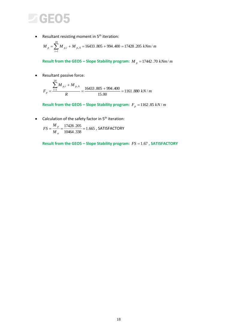
Resultant resisting moment in 5th iteration:
mkNmMMM Ap
i
ipp /205.17428400.994805.16433,
20
1
,
Result from the GEO5 – Slope Stability program: mkNmM p /70.17442
Resultant passive force:
mkNR
MM
F
Ap
i
ip
p /880.116100.15
400.994805.16433,
20
1
,
Result from the GEO5 – Slope Stability program: mkNFp /85.1162
Calculation of the safety factor in 5th iteration:
665.1338.10464
205.17428
a
p
M
MFS , SATISFACTORY
Result from the GEO5 – Slope Stability program: 67.1FS , SATISFACTORY