VEM motors GmbHThe motors have been manufactured in accordance with IEC 34-1, DIN EN 60034-1, DIN...
19
1 VEM motors GmbH Wernigerode _____________________________________________________ Installation, Operating and Maintenance Instructions for Converter-Fed Synchronous Motors with Permanent-Magnet Rotor 74198 01 englisch _____________________________________________________ 1. General To prevent damage to motors and the driven equipment the procedures laid down in the Operating and Maintenance Instructions must be followed. Especially to avoid risk of injury, the Safety Regulations must be adhered to strictly. Since for reasons of clarity the Operating and Maintenance Instructions cannot contain specific information with regard to all conceivable special applications and areas with special requirements, the user himself has to make appropriate protection arrangements during the installation process. 2. Description The motors have been manufactured in accordance with IEC 34-1, DIN EN 60034-1, DIN VDE 0530 and other appropriate DIN standards. Motors can also be supplied to comply with special regulations (e.g. Classification Regulations, Regulations for Explosion Protection). The details on the relevant Order Confirmation constitute the scope of supply. 3. Degree of Protection The degree of protection of the motors is indicated on their rating plate. The degree of protection of additional devices fitted to the motor can be different than the degree of protection of the motor. This needs to be taken into consideration during the installation of the motors. If motors are installed in the open (Degree of Protection ≥ IP 44), they should be protected against direct effects of the climate (freezing of the fan due to direct fall of rain, snow and formation of ice). 4. Type of Construction The type of construction of the motors is indicated on the rating plate. The motors can be used in different types of construction only with permission of the manufacturer and if necessary after modification carried out in accordance with the manufacturer’s instructions. Especially with types of construction with vertical shaft the user has to ensure that foreign particles cannot fall into the fan cowl. 5. Transport & Storage If possible the motors should only be stored in closed and dry rooms. Outdoor storage under cover is permitted for a short time only and requires adequate protection against all harmful effects of the climate. The motors also have to be protected against mechanical damage. Never transport or store the motors resting on their fan cowls. The eye bolts of the motors together with appropriate lifting tackle must be used for transport. The eye bolts are intended for the lifting of the motors only, without any additional parts such as bed plates, gears etc. Before using the eye bolts, their intactness must be checked. If eye bolts are removed after installation, the tapped holes must be blanked off permanently according to the Protection Standard. 6. Installation and Fitting Since during normal operation of electric motors, temperatures in excess of 100 °C can occur on their surface, any contact with them must be prevented if the motors are installed in accessible areas. Because of this temperature sensitive parts must never be fitted to them or have contact with them. Vent holes must be kept free and the minimum distances stated in the dimensional drawings must be maintained so that the flow of cooling air is not obstructed. Care must be taken that the discharged warmed up cooling medium is not sucked up again. The key in the shaft end is secured by the shaft protective sleeve for transport and storage only. Because of the danger that the key may be thrown aside, a start-up or a trial run with the key protected by the shaft sleeve only is strictly forbidden.
Transcript of VEM motors GmbHThe motors have been manufactured in accordance with IEC 34-1, DIN EN 60034-1, DIN...
1
VEM motors GmbH Wernigerode
_____________________________________________________ Installation, Operating and Maintenance Instructions for Converter-Fed Synchronous Motors with Permanent-Magnet Rotor 74198 01 englisch
_____________________________________________________ 1. General To prevent damage to motors and the driven equipment the procedures laid down in the Operating and Maintenance Instructions must be followed. Especially to avoid risk of injury, the Safety Regulations must be adhered to strictly. Since for reasons of clarity the Operating and Maintenance Instructions cannot contain specific information with regard to all conceivable special applications and areas with special requirements, the user himself has to make appropriate protection arrangements during the installation process. 2. Description The motors have been manufactured in accordance with IEC 34-1, DIN EN 60034-1, DIN VDE 0530 and other appropriate DIN standards. Motors can also be supplied to comply with special regulations (e.g. Classification Regulations, Regulations for Explosion Protection). The details on the relevant Order Confirmation constitute the scope of supply. 3. Degree of Protection The degree of protection of the motors is indicated on their rating plate. The degree of protection of additional devices fitted to the motor can be different than the degree of protection of the motor. This needs to be taken into consideration during the installation of the motors. If motors are installed in the open (Degree of Protection ≥ IP 44), they should be protected against direct effects of the climate (freezing of the fan due to direct fall of rain, snow and formation of ice). 4. Type of Construction The type of construction of the motors is indicated on the rating plate. The motors can be used in different types of construction only with permission of the manufacturer and if necessary after modification carried out in accordance with the manufacturer’s instructions. Especially with types of construction with vertical shaft the user has to ensure that foreign particles cannot fall into the fan cowl. 5. Transport & Storage If possible the motors should only be stored in closed and dry rooms. Outdoor storage under cover is permitted for a short time only and requires adequate protection against all harmful effects of the climate. The motors also have to be protected against mechanical damage. Never transport or store the motors resting on their fan cowls. The eye bolts of the motors together with appropriate lifting tackle must be used for transport. The eye bolts are intended for the lifting of the motors only, without any additional parts such as bed plates, gears etc. Before using the eye bolts, their intactness must be checked. If eye bolts are removed after installation, the tapped holes must be blanked off permanently according to the Protection Standard. 6. Installation and Fitting Since during normal operation of electric motors, temperatures in excess of 100 °C can occur on their surface, any contact with them must be prevented if the motors are installed in accessible areas. Because of this temperature sensitive parts must never be fitted to them or have contact with them. Vent holes must be kept free and the minimum distances stated in the dimensional drawings must be maintained so that the flow of cooling air is not obstructed. Care must be taken that the discharged warmed up cooling medium is not sucked up again. The key in the shaft end is secured by the shaft protective sleeve for transport and storage only. Because of the danger that the key may be thrown aside, a start-up or a trial run with the key protected by the shaft sleeve only is strictly forbidden.

2
Transmission components (such as couplings, pinions or belt pulleys) should be drawn onto the shaft by means of pull-on devices or by heating-up the part to be drawn onto the shaft. For the purpose of drawing the transmission components onto the shaft, the shaft ends are provided with tapped centering holes according to DIN 332 Part 2. Transmission components must never be driven onto the shaft using hammer blows because the shaft, the bearings and other components of the motor could be damaged. All components that are to be fitted to the shaft end must be balanced dynamically according to the balancing system of the motor (full or half key). The rotors of the motor are balanced with half key; this is indicated by letter H after the serial number on the rating plate. Motors with letter F after the serial number are balanced with full key. If possible the motors are to be installed in such a way that they are free from vibrations. Direct coupling to the driven machine requires a particularly accurate alignment. The shafts of both machines must be in alignment. The shaft height is to be adjusted to that of the driven machine using appropriate shims. Belt drives put a lot of stress on the motor because of relatively high radial forces. When dimensioning belt drives, apart from the instructions and calculation programmes issued by the manufacturers of the belts, it must be ensured that the radial force permissible at the shaft end of the motor as stated in our data is never exceeded by the pull and pre-tensioning of the belt. When pre-tensioning the belt during installation the instructions of the belt manufacturers must be strictly adhered to. 7. Commissioning
Synchronous motors with permanent-magnet rotor are not suitable for direct on-line starting. For converter feeding, before commissioning must be exactly checked that the converter is suitable for feeding the synchronous motor. If there are any doubts, please contact the manufacturers of both components.
During their mounting and dismantling, synchronous motors with permanent-magnet rotor emit magnetic stray fields, particularly the rotors of these motors can disturb or damage other electrical or electronical apparatus and devices. This is especially important for cardiac pacemakers, mobile electronic devices and credit cards.
For synchronous motors, as they are fed by converters, particular safety regulations must be observed. This means, that these motors, also after complete shut-off of the electrical connections and at standstill, can have dangerous voltages at their terminals. Furthermore, with open terminal box, it must be always observed that the motor shaft is block against rotation. During working at the cabling, reverse voltages can occur. Converter feeding of the motor can result in voltages being present at the motor terminals, also if the motor is in standstill. If the synchronous motor with permanent-magnet rotor is overloaded, this can cause, due to demagnetisation, winding damages. The maximum allowed speed of the motor is limited to 1,2 times of the nominal speed, given on the nameplate, higher speed can result in damages of the drive system.
This dismantling of the rotor must always be done with special tools, designed for this particular purpose, ignoring this fact results in serious personal injuries and material damages. During assembling of the permanent-magnet rotor, it must be strictly observed, that no wast or metallic parts remain on the rotor surface or the stator bore hole. Please follow the Safety Regulations closely. All work is to be carried out only when there is no voltage on the motor. The installation must be carried out according to the valid regulations by qualified skilled personnel. Initially the mains conditions (voltage and frequency) must be compared with the data on the rating plate of the motor. The dimensions of the connecting cables must be adjusted in line with the rated currents of the motor. The connection points of the motor are marked in accordance with DIN VDE 0530 Part 8 (DIN EN 60034-8). In Section 17 of these instructions the most common circuit diagrams for three phase motors in basic design are provided, according to which the connection will be implemented. For all other versions, the special circuit diagrams are glued to the inside of the terminal box cover or
3
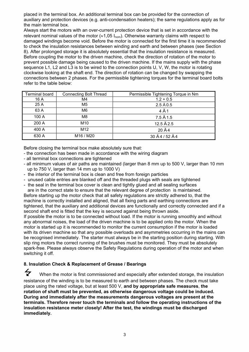
placed in the terminal box. An additional terminal box can be provided for the connection of auxiliary and protection devices (e.g. anti-condensation heaters); the same regulations apply as for the main terminal box. Always start the motors with an over-current protection device that is set in accordance with the relevant nominal values of the motor (≈1,05 Inom). Otherwise warranty claims with respect to damaged windings become void. Before the motor is connected for the first time it is recommended to check the insulation resistances between winding and earth and between phases (see Section 8). After prolonged storage it is absolutely essential that the insulation resistance is measured. Before coupling the motor to the driven machine, check the direction of rotation of the motor to prevent possible damage being caused to the driven machine. If the mains supply with the phase sequence L1, L2 and L3 is to be wired to the connection points U, V, W, the motor is rotating clockwise looking at the shaft end. The direction of rotation can be changed by swapping the connections between 2 phases. For the permissible tightening torques for the terminal board bolts refer to the table below: Terminal board Connecting Bolt Thread Permissible Tightening Torque in Nm
16 A M4 1.2 + 0.5 25 A M5 2.5 Ä 0.5 63 A M6 4 Ä 1 100 A M8 7.5 Ä 1.5 200 A M10 12.5 Ä 2.5 400 A M12 20 Ä 4 630 A M16 / M20 30 Ä 4 / 52 Ä 4
Before closing the terminal box make absolutely sure that: - the connection has been made in accordance with the wiring diagram - all terminal box connections are tightened - all minimum values of air paths are maintained (larger than 8 mm up to 500 V, larger than 10 mm
up to 750 V, larger than 14 mm up to 1000 V) - the interior of the terminal box is clean and free from foreign particles - unused cable entries are blanked off and the threaded plugs with seals are tightened - the seal in the terminal box cover is clean and tightly glued and all sealing surfaces are in the correct state to ensure that the relevant degree of protection is maintained. Before starting up the motor check that all safety regulations are strictly adhered to, that the machine is correctly installed and aligned, that all fixing parts and earthing connections are tightened, that the auxiliary and additional devices are functionally and correctly connected and if a second shaft end is fitted that the key is secured against being thrown aside. If possible the motor is to be connected without load. If the motor is running smoothly and without any abnormal noises, the load of the driven machine is to be applied onto the motor. When the motor is started up it is recommended to monitor the current consumption if the motor is loaded with its driven machine so that any possible overloads and asymmetries occurring in the mains can be recognised immediately. The starter must always be in the starting position during starting. With slip ring motors the correct running of the brushes must be monitored. They must be absolutely spark-free. Please always observe the Safety Regulations during operation of the motor and when switching it off. 8. Insulation Check & Replacement of Grease / Bearings
When the motor is first commissioned and especially after extended storage, the insulation resistance of the winding is to be measured to earth and between phases. The check must take place using the rated voltage, but at least 500 V, and by appropriate safe measures, the rotation of shaft must be prevented, as otherwise dangerous voltage could be induced. During and immediately after the measurements dangerous voltages are present at the terminals. Therefore never touch the terminals and follow the operating instructions of the insulation resistance meter closely! After the test, the windings must be discharged immediately.

4
Depending on the rated voltage UN, the following minimum values must be maintained with a winding temperature of 25 °C:
Rated Power PN Insulation Resistance referred to kW Rated Voltage kΩ/V
1 < PN ≤ 10 6.3 10 < PN ≤ 100 4
100 < PN 2.5 If the minimum values are lower, the winding must be dried properly until the insulation resistance corresponds to the required value. When the motor is commissioned after a prolonged period of storage inspect the bearing grease visually and replace it if hardening and other irregularities occur. If the motors are to be commissioned by the manufacturer after more than three years following their delivery then the bearing grease must always be replaced. With motors fitted with covered or sealed bearings the bearings must always be replaced with new bearings of the same type after a storage period of four years. 9. Maintenance
You are once again referred to the Safety Regulations, in particular to isolation, to securing against reconnection, to checking whether all components connected to a voltage source are in dead state. If it is necessary to disconnect the motor from the mains for maintenance work particular care must be taken to ensure that any possibly existing auxiliary circuits (e.g. anti-condensation heaters, forced ventilators, brakes) are also disconnected from the mains. If the motor is to be dismantled during maintenance work, the sealing compound on the centering shoulders is to be removed. When re-assembling the motor these need to be re-sealed using a suitable motor sealing compound. Existing copper sealing washers must always be refitted.
If bearings are changed, this must be done without removing the rotor from the stator. 10. Bearings and Lubrication The anti-friction bearings of the motors are filled with anti-friction bearing grease in the factory (or with sealed bearings by the bearing manufacturer) according to DIN 51825 in compliance with the table below:
Type series Lubricating grease according to DIN 51825 Lubricating Grease BaseAll Squirrel Cage motors IEC/DIN 132 – 355 and
Progressive standard 112 – 315 Forced Ventilated motors
Brake motors KE2R-40 Polyurethane base Marine Motors for on board ship K2N-30
Under normal load and climatic conditions, the quality of grease guarantees an operation of the motor for approx. 10,000 service hours with two pole design and 20,000 service hours with multipole design. If not otherwise agreed the grease of anti-friction bearing must never be refilled during this period. However, the condition of the grease should be checked occasionally even before this time limit. The indicated number of service hours is only valid for operation at rated speed. If during operation of the motor via an inverter the nominal speed is exceeded then the regreasing period reduces approximately in the opposite ratio to the increase in the motor speed. Regrease the bearings only after a thorough cleaning using suitable solvents. The same type of grease must be used. When replacing the grease only the equivalent types specified by the motor manufacturer can be used. Please bear in mind that the bearings should only be filled up to about 2/3 of their free space. A complete filling of the bearings and bearing covers with grease leads to increased bearing temperature and therefore to increased wear.
5
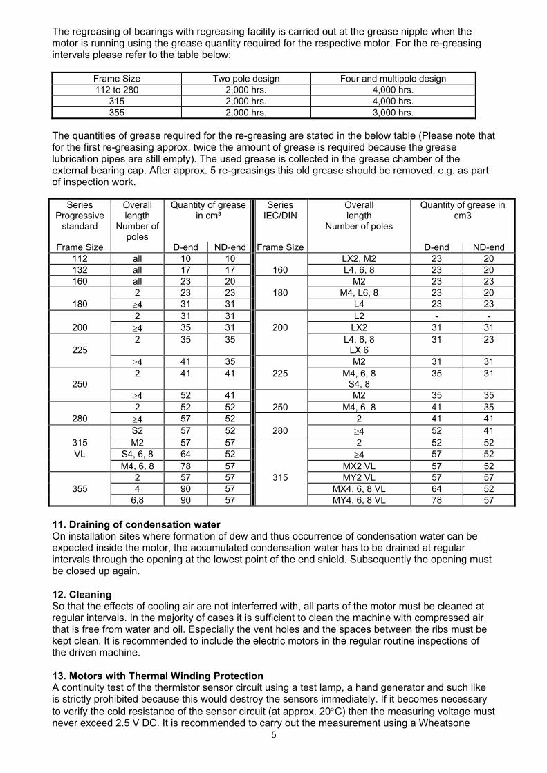
The regreasing of bearings with regreasing facility is carried out at the grease nipple when the motor is running using the grease quantity required for the respective motor. For the re-greasing intervals please refer to the table below:
Frame Size Two pole design Four and multipole design 112 to 280 2,000 hrs. 4,000 hrs.
315 2,000 hrs. 4,000 hrs. 355 2,000 hrs. 3,000 hrs.
The quantities of grease required for the re-greasing are stated in the below table (Please note that for the first re-greasing approx. twice the amount of grease is required because the grease lubrication pipes are still empty). The used grease is collected in the grease chamber of the external bearing cap. After approx. 5 re-greasings this old grease should be removed, e.g. as part of inspection work.
Series Progressive
standard
Overall length
Number of poles
Quantity of grease in cm³
Series IEC/DIN
Overall length
Number of poles
Quantity of grease in cm3
Frame Size D-end ND-end Frame Size D-end ND-end 112 all 10 10 LX2, M2 23 20 132 all 17 17 160 L4, 6, 8 23 20 160 all 23 20 M2 23 23
2 23 23 180 M4, L6, 8 23 20 180 ≥4 31 31 L4 23 23
2 31 31 L2 - - 200 ≥4 35 31 200 LX2 31 31
225
2 35 35 L4, 6, 8 LX 6
31 23
≥4 41 35 M2 31 31
250 2 41 41 225 M4, 6, 8
S4, 8 35 31
≥4 52 41 M2 35 35 2 52 52 250 M4, 6, 8 41 35
280 ≥4 57 52 2 41 41 S2 57 52 280 ≥4 52 41
315 M2 57 57 2 52 52 VL S4, 6, 8 64 52 ≥4 57 52
M4, 6, 8 78 57 MX2 VL 57 52 2 57 57 315 MY2 VL 57 57
355 4 90 57 MX4, 6, 8 VL 64 52 6,8 90 57 MY4, 6, 8 VL 78 57
11. Draining of condensation water On installation sites where formation of dew and thus occurrence of condensation water can be expected inside the motor, the accumulated condensation water has to be drained at regular intervals through the opening at the lowest point of the end shield. Subsequently the opening must be closed up again. 12. Cleaning So that the effects of cooling air are not interferred with, all parts of the motor must be cleaned at regular intervals. In the majority of cases it is sufficient to clean the machine with compressed air that is free from water and oil. Especially the vent holes and the spaces between the ribs must be kept clean. It is recommended to include the electric motors in the regular routine inspections of the driven machine. 13. Motors with Thermal Winding Protection A continuity test of the thermistor sensor circuit using a test lamp, a hand generator and such like is strictly prohibited because this would destroy the sensors immediately. If it becomes necessary to verify the cold resistance of the sensor circuit (at approx. 20°C) then the measuring voltage must never exceed 2.5 V DC. It is recommended to carry out the measurement using a Wheatsone

6
bridge with a 4.5 V DC supply voltage. The cold resistance of the sensor circuit must never exceed 810 Ohms; a measurement of the hot resistance is not necessary. With motors that are fitted with thermal winding protection, care must be taken that when the thermal winding protection responds and after the cooling down of the motor, no hazards can occur due to spurious automatic reconnection. 14. Warranty, Repair, Spare Parts Unless expressly agreed otherwise only our contractual workshops are permitted to carry out repairs during the warranty period. Other repairs that may potentially be required can also be carried out by skilled personnel in these workshops. Details about Customer Service network can be obtained from the manufacturer on request. The spare parts are listed in Section 20 of these Operating & Maintenance Instructions. Maintenance carried out appropriately (provided it is as described in Section “Maintenance”) does not constitute a breach of warranty provisions. The contractual warranty liability on the part of the manufacturer is not prejudiced by this. 15. Electromagnetic Compatibility The motors, as non-independently working unit, have been checked with regard to their conformity with the EMC Standards. It is the responsibility of the equipment operator to ensure by suitable measures that the apparatus or plant in their entirety comply with the relevant electromagnetic compatibility standards. 16. Trouble Shooting General mechanical and electrical faults are to be rectified according to the Schedule in Section 19. All Safety Regulations must be strictly observed when rectifying faults. 17. Terminal board circuits Single Speed Squirrel Cage Motor : Single Speed Squirrel Cage Motor: ∆ low voltage Y high voltage
Motor with thermal winding protection Terminal board connection as above connection of the tripping device from the motor
The connection will be implemented as per the connection diagramme of the tripping device
TP1 (T1)
TP2 (T2)
7
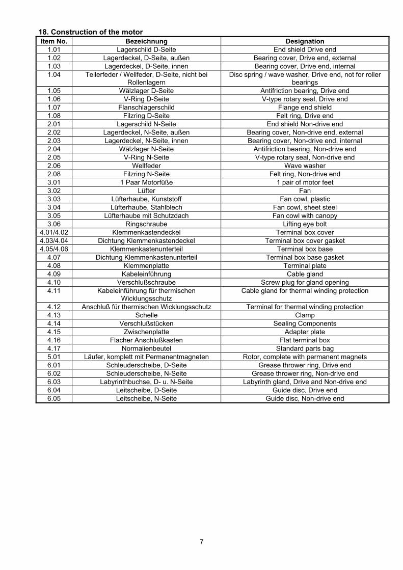
18. Construction of the motorItem No. Bezeichnung Designation
1.01 Lagerschild D-Seite End shield Drive end 1.02 Lagerdeckel, D-Seite, außen Bearing cover, Drive end, external 1.03 Lagerdeckel, D-Seite, innen Bearing cover, Drive end, internal 1.04 Tellerfeder / Wellfeder, D-Seite, nicht bei
Rollenlagern Disc spring / wave washer, Drive end, not for roller
bearings 1.05 Wälzlager D-Seite Antifriction bearing, Drive end 1.06 V-Ring D-Seite V-type rotary seal, Drive end 1.07 Flanschlagerschild Flange end shield 1.08 Filzring D-Seite Felt ring, Drive end 2.01 Lagerschild N-Seite End shield Non-drive end 2.02 Lagerdeckel, N-Seite, außen Bearing cover, Non-drive end, external 2.03 Lagerdeckel, N-Seite, innen Bearing cover, Non-drive end, internal 2.04 Wälzlager N-Seite Antifriction bearing, Non-drive end 2.05 V-Ring N-Seite V-type rotary seal, Non-drive end 2.06 Wellfeder Wave washer 2.08 Filzring N-Seite Felt ring, Non-drive end 3.01 1 Paar Motorfüße 1 pair of motor feet 3.02 Lüfter Fan 3.03 Lüfterhaube, Kunststoff Fan cowl, plastic 3.04 Lüfterhaube, Stahlblech Fan cowl, sheet steel 3.05 Lüfterhaube mit Schutzdach Fan cowl with canopy 3.06 Ringschraube Lifting eye bolt
4.01/4.02 Klemmenkastendeckel Terminal box cover 4.03/4.04 Dichtung Klemmenkastendeckel Terminal box cover gasket 4.05/4.06 Klemmenkastenunterteil Terminal box base
4.07 Dichtung Klemmenkastenunterteil Terminal box base gasket 4.08 Klemmenplatte Terminal plate 4.09 Kabeleinführung Cable gland 4.10 Verschlußschraube Screw plug for gland opening 4.11 Kabeleinführung für thermischen
Wicklungsschutz Cable gland for thermal winding protection
4.12 Anschluß für thermischen Wicklungsschutz Terminal for thermal winding protection 4.13 Schelle Clamp 4.14 Verschlußstücken Sealing Components 4.15 Zwischenplatte Adapter plate 4.16 Flacher Anschlußkasten Flat terminal box 4.17 Normalienbeutel Standard parts bag 5.01 Läufer, komplett mit Permanentmagneten Rotor, complete with permanent magnets 6.01 Schleuderscheibe, D-Seite Grease thrower ring, Drive end 6.02 Schleuderscheibe, N-Seite Grease thrower ring, Non-drive end 6.03 Labyrinthbuchse, D- u. N-Seite Labyrinth gland, Drive and Non-drive end 6.04 Leitscheibe, D-Seite Guide disc, Drive end 6.05 Leitscheibe, N-Seite Guide disc, Non-drive end
8
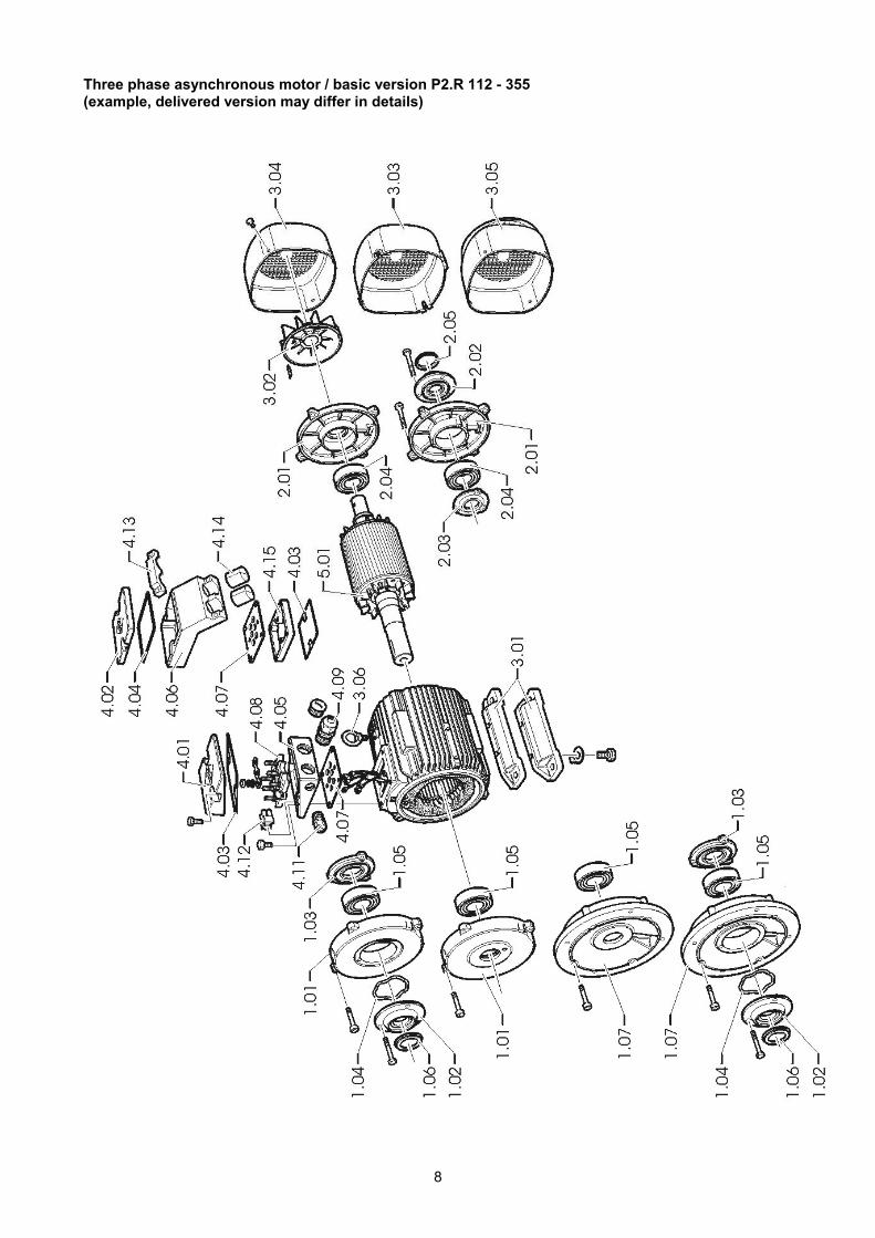
Three phase asynchronous motor / basic version P2.R 112 - 355 (example, delivered version may differ in details)

9
19. Trouble shooting 19.1 Electrical Faults
Motor doesn't start Motor runs up heavily Humming noise during start Humming noise during operation Hum in time of the double slip frequency Excessive warming up at no-load
operation Excessive warming up at rated output Excessive warming up of individual winding sections Possible cause of fault Remedial measure Overload Decrease the load Interruption of a phase in the supply
conductor check the switch and the supply conductor Interruption of a phase in the supply conductor after switching-on check the switch and the supply conductor Mains voltage too low, frequency too high check the mains conditions Mains voltage too high, frequency too low check the mains conditions Stator winding misconnected check the winding connections Turn-to-turn fault check the winding and the insulation resistance,
repair in authorized service workshop Phase-to-phase short circuit check the winding and the insulation resistance,
repair in authorized service workshop Interruption in the squirrel cage winding repair in authorized service workshop
10
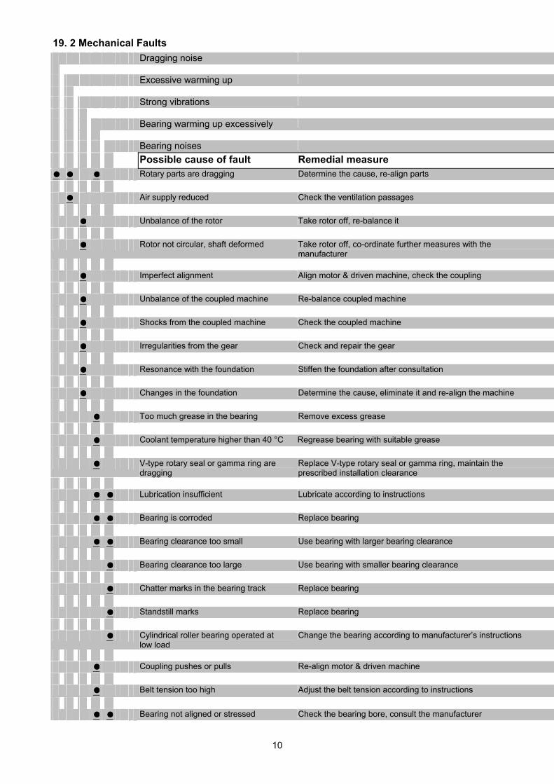
19. 2 Mechanical Faults
Dragging noise Excessive warming up Strong vibrations Bearing warming up excessively Bearing noises
Possible cause of fault Remedial measure Rotary parts are dragging Determine the cause, re-align parts Air supply reduced Check the ventilation passages Unbalance of the rotor Take rotor off, re-balance it Rotor not circular, shaft deformed Take rotor off, co-ordinate further measures with the
manufacturer Imperfect alignment Align motor & driven machine, check the coupling Unbalance of the coupled machine Re-balance coupled machine Shocks from the coupled machine Check the coupled machine Irregularities from the gear Check and repair the gear Resonance with the foundation Stiffen the foundation after consultation Changes in the foundation Determine the cause, eliminate it and re-align the machine Too much grease in the bearing Remove excess grease Coolant temperature higher than 40 °C Regrease bearing with suitable grease V-type rotary seal or gamma ring are
dragging Replace V-type rotary seal or gamma ring, maintain the prescribed installation clearance
Lubrication insufficient Lubricate according to instructions Bearing is corroded Replace bearing Bearing clearance too small Use bearing with larger bearing clearance Bearing clearance too large Use bearing with smaller bearing clearance Chatter marks in the bearing track Replace bearing Standstill marks Replace bearing Cylindrical roller bearing operated at
low load Change the bearing according to manufacturer’s instructions
Coupling pushes or pulls Re-align motor & driven machine Belt tension too high Adjust the belt tension according to instructions Bearing not aligned or stressed Check the bearing bore, consult the manufacturer
Ausgabe / Edition 12.2004 Seite 1 / page 1 Ident-No. VEM 73753 01 / d / e
VEM motors GmbH
Ergänzende Montage-, Bedienungs- und Wartungsanleitung
Wassergekühlte Drehstrom-Asynchronmotoren
Baureihe K2.B
Additional Installation, Operating and Maintenance Instructions
Water Cooled Three-Phase Asynchronous Motors Serie K2.B

Ausgabe / Edition 12.2004 Seite 2 / page 2 Ident-No. VEM 73753 01 / d / e
1. Konformitätserklärung Dezember 2004
VEM motors GmbH Werknorm EW-N 1200 Elektromotorenwerk EG-Konformitätserklärung
Wernigerode Blatt 1 Seite 14
Die elektrischen Betriebsmittel wassergekühlte asynchrone Drehstrommotoren mit Käfigläufer,
der Reihen K21B / K23B 225 bis 315
stimmen mit den Vorschriften folgender Europäischer Richtlinien überein: 73/23/EWG
Richtlinie des Rates zur Rechtsangleichung der Rech tsvorschriften der Mitgliedstaaten betreffend elektrische Betriebsmittel zur Verwendun g innerhalb bestimmter Spannungsgrenzen, geändert durch RL 93/68 /EWG 89/336/EWG
Richtlinie des Rates zur Rechtsangleichung der Rech tsvorschriften der Mitgliedstaaten über die elektromagnetische Verträglichkeit, geändert durch RL 91/263/EWG, 92/31/EWG und 93/68/EWG Die Übereinstimmung mit den Vorschriften dieser Richtlinien wird durch die Einhaltung nachstehender Normen nachgewiesen: Europäische Norm / Deutsche Norm EN 61000-6-1, EN 61000-6-2, EN 61000-6-3, EN 61000-6-4 EN 55014-1, EN 55014-2 EN 61000-3-2, EN 61000-3-3 EN 60034-1, DIN EN 60034-2, EN 60034-5, EN 60034-6, EN 60034-9, DIN IEC 60038 EN 61800-3 + A11 EN 60204-1
Wernigerode, d. 10.12. 2004
gez. Sander gez. Beutner Geschäftsführer Werkleiter
Diese Erklärung bescheinigt die Übereinstimmung mit den genannten Richtlinien, ist jedoch keine Zusicherung von Eigenschaften im Sinne der Produkthaftung. 2. Allgemeines Zur Vermeidung von Schäden an den Motoren und den anzutreibenden Ausrüstungen sind die Bestimmungen der Bedienungs- und Wartungsanleitung einzuhalten. Insbesondere müssen zur Vermeidung von Gefahren die Sicherheitshinweise, die gesondert beiliegen, streng beachtet werden. Da die Bedienungs- und Wartungsanlei-tung zur besseren Übersichtlichkeit keine einzelnen Informationen für alle denkbaren Sondereinsatzgebiete und Bereiche mit speziellen Anforderungen enthalten kann, sind bei der Montage durch den Betreiber entsprechen-de Schutzvorkehrungen zu treffen. Diese ergänzende Montage-, Bedienungs- und Wartungsanleitung gilt für wassergekühlte Motoren der Baureihe K21B / K23B. Neben diesen Hinweisen ist unbedingt die
Montage-, Bedienungs- und Wartungsanleitung Drehstr om-Asynchronmotoren mit Käfigläufer und mit Schleifringläufer, Normalausführung, VEM-Id.-Nr. 68238 01
zu befolgen. Für Sonderausführungen und/oder weitere spezielle Anwendungen werden gegebenenfalls zusätz-liche Montage-, Bedienungs- und Watungshinweise benötigt. 3. Konstruktive Ausführung
Achshöhe Baureihe Werkstoffe für Fußbefestigung Gehäuse Lagerschilde Füße
225 bis 280 Grauguß mit Stahl angeschraubt
315 K21B / K23B eingegossenen
Kühlrohren Grauguß
Grauguß
angegossen
Ausgabe / Edition 12.2004 Seite 3 / page 3 Ident-No. VEM 73753 01 / d / e
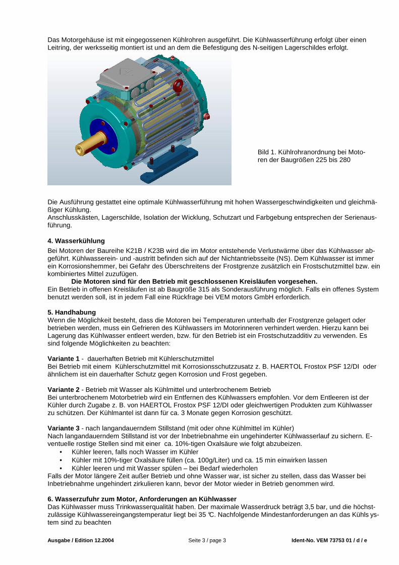
Das Motorgehäuse ist mit eingegossenen Kühlrohren ausgeführt. Die Kühlwasserführung erfolgt über einen Leitring, der werksseitig montiert ist und an dem die Befestigung des N-seitigen Lagerschildes erfolgt. Die Ausführung gestattet eine optimale Kühlwasserführung mit hohen Wassergeschwindigkeiten und gleichmä-ßiger Kühlung. Anschlusskästen, Lagerschilde, Isolation der Wicklung, Schutzart und Farbgebung entsprechen der Serienaus-führung.
4. Wasserkühlung Bei Motoren der Baureihe K21B / K23B wird die im Motor entstehende Verlustwärme über das Kühlwasser ab-geführt. Kühlwasserein- und -austritt befinden sich auf der Nichtantriebsseite (NS). Dem Kühlwasser ist immer ein Korrosionshemmer, bei Gefahr des Überschreitens der Frostgrenze zusätzlich ein Frostschutzmittel bzw. ein kombiniertes Mittel zuzufügen.
Die Motoren sind für den Betrieb mit geschlossenen Kreisläufen vorgesehen. Ein Betrieb in offenen Kreisläufen ist ab Baugröße 315 als Sonderausführung möglich. Falls ein offenes System benutzt werden soll, ist in jedem Fall eine Rückfrage bei VEM motors GmbH erforderlich. 5. Handhabung Wenn die Möglichkeit besteht, dass die Motoren bei Temperaturen unterhalb der Frostgrenze gelagert oder betrieben werden, muss ein Gefrieren des Kühlwassers im Motorinneren verhindert werden. Hierzu kann bei Lagerung das Kühlwasser entleert werden, bzw. für den Betrieb ist ein Frostschutzadditiv zu verwenden. Es sind folgende Möglichkeiten zu beachten: Variante 1 - dauerhaften Betrieb mit Kühlerschutzmittel Bei Betrieb mit einem Kühlerschutzmittel mit Korrosionsschutzzusatz z. B. HAERTOL Frostox PSF 12/DI oder ähnlichem ist ein dauerhafter Schutz gegen Korrosion und Frost gegeben. Variante 2 - Betrieb mit Wasser als Kühlmittel und unterbrochenem Betrieb Bei unterbrochenem Motorbetrieb wird ein Entfernen des Kühlwassers empfohlen. Vor dem Entleeren ist der Kühler durch Zugabe z. B. von HAERTOL Frostox PSF 12/DI oder gleichwertigen Produkten zum Kühlwasser zu schützen. Der Kühlmantel ist dann für ca. 3 Monate gegen Korrosion geschützt. Variante 3 - nach langandauerndem Stillstand (mit oder ohne Kühlmittel im Kühler) Nach langandauerndem Stillstand ist vor der Inbetriebnahme ein ungehinderter Kühlwasserlauf zu sichern. E-ventuelle rostige Stellen sind mit einer ca. 10%-tigen Oxalsäure wie folgt abzubeizen.
• Kühler leeren, falls noch Wasser im Kühler • Kühler mit 10%-tiger Oxalsäure füllen (ca. 100g/Liter) und ca. 15 min einwirken lassen • Kühler leeren und mit Wasser spülen – bei Bedarf wiederholen
Falls der Motor längere Zeit außer Betrieb und ohne Wasser war, ist sicher zu stellen, dass das Wasser bei Inbetriebnahme ungehindert zirkulieren kann, bevor der Motor wieder in Betrieb genommen wird. 6. Wasserzufuhr zum Motor, Anforderungen an Kühlwas ser Das Kühlwasser muss Trinkwasserqualität haben. Der maximale Wasserdruck beträgt 3,5 bar, und die höchst-zulässige Kühlwassereingangstemperatur liegt bei 35 °C. Nachfolgende Mindestanforderungen an das Kühls ys-tem sind zu beachten
Bild 1. Kühlrohranordnung bei Moto-ren der Baugrößen 225 bis 280

Ausgabe / Edition 12.2004 Seite 4 / page 4 Ident-No. VEM 73753 01 / d / e
Motortyp K21B / K23B
Kühlwasser-Durchflussmenge [l/min]
Mindestwasserdruck [bar]
Kühlwasser-Temperaturanstieg [°C]
225 10 0,5 6 250 16 0,7 7 280 18 1,0 9 315 20 1,5 12
Auf der Nichtantriebsseite der Motoren (N-Seite) befinden sich rechts und links zwei Gewindebohrungen ¾’’ (siehe Bild 2). Sie sind wahlweise als Zu- oder Ablauf nutzbar. Verbinden Sie die eine Seite mit dem Wasserzu-lauf und die gegenüberliegende mit dem Wasserablauf. An den Verbindungsstellen sind geeignete Dichtmittel zu verwenden. Die Wasserversorgung muss während des Betriebs des Motors ständig gewährleistet sein.
Ein Betrieb ohne Kühlwasser ist unzulässig. Auf der N-Seite befinden sich weiterhin oben ein Entlüftungsstopfen 3/8’’ und an der tiefsten Stelle ein Wasser-ablaufstopfen 3/8’’. Beim Befüllen des Kühlkreislaufs ist der Entlüftungsstutzen zu öffnen. Der Motor ist mit Kühlwasser zu befüllen, bis Wasser aus der Entlüftungsöffnung austritt. Dabei sorgfältig vorgehen, damit keine Luft im Kühlkreislauf verbleibt. Danach ist die Entlüftungsöffnung zu verschließen. Dabei ist wiederum ein ge-eignetes Dichtmittel zu verwenden. Dichtung der Verbindungen prüfen. Zum Entleeren des Motors sind Entlüftungs- und Wasserablaufstopfen zu entfernen. Nach dem Entleeren die Stopfen wieder einschrauben. Bei erneuter Befüllung Dichtheit der Stopfen prüfen.
7. Schutzart Die Normalausführung der Motoren entspricht der Schutzart IP 55, die je nach Bestellung auf IP 56 erhöht wer-den kann. Schutzarten IP 65 und höher sind auf Anfrage möglich. Bei allen Motoren in Bauformen mit dem Wellenende nach oben (IM V3/IM V36) muss seitens des Anwenders das Eindringen von Wasser entlang der Welle verhindert werden Bei Flanschmotoren in Bauform IM V3 / IM V36 wird das Ansammeln von Flüssigkeit im Flanschteller durch ein serienmäßiges Abflussloch vermieden. Für eine Aufstellung im Freien sind im Normalfall keine besonderen zusätzlichen Schutzmaßnahmen gegen Witterungseinflüsse erforderlich. Wenn die Möglichkeit besteht, dass die Motoren bei Temperaturen unterhalb der Frostgrenze gelagert oder betrieben werden, muss ein Gefrieren des Kühlwassers im Motorinneren verhin-dert werden. Die Motoren müssen aber auch vor intensiver Sonneneinstrahlung, z.B. durch ein Schutzdach geschützt werden. 8. Kondenswasserablauf Alle Motoren haben auf der Antriebs- und Nichtantriebsseite Kondenswasserablaufschrauben, die im Ausliefer-zustand verschlossen sind. Bei Inbetriebnahme der Motoren sind die Kondenswasserabläufe zu öffnen. Die Öffnungen müssen zwingend nach unten gerichtet sein, da es sonst zu gefährlichen Schwitzwasseransamm-lungen im Motor kommen kann.
Bild 2: Be- und Entwässe-rungsöffnungen

Ausgabe / Edition 12.2004 Seite 5 / page 5 Ident-No. VEM 73753 01 / d / e
1. Declaration of Conformity December 2004
VEM motors GmbH Factory Standard EW-N 1200 Elektromotorenwerk EC Declaration of Conformity
Wernigerode Sheet 1 Page 14
The electrical apparatus Water cooled three-phase asynchronous motors with squirrel-cage rotor,
of series K21B / K23B 225 up to 315
are in conformity with the instructions of the following EU Directives: 73/23/EWG
Low Voltage Directive amended by Directive 93/68 /EWG 89/336/EWG
Directive about Electromagnetic Compatibility amended by Directives 91/263/EWG, 92/31/EWG und 93/68/EWG The conformity with the instructions of these Directives is proved by the observations of following standards: European Standard / German Standard EN 61000-6-1, EN 61000-6-2, EN 61000-6-3, EN 61000-6-4 EN 55014-1, EN 55014-2 EN 61000-3-2, EN 61000-3-3 EN 60034-1, DIN EN 60034-2, EN 60034-5, EN 60034-6, EN 60034-9, DIN IEC 60038 EN 61800-3 + A11 EN 60204-1
Wernigerode, 10th of December 2004
Sander Beutner Managing Director Factory Manager
This certificate attests the conformity with the named Directives, however, it is not a promise of properties in the meaning of product liability. 1. General To prevent damage to motors and the driven equipment the procedures laid down in the Operating and Mainte-nance Instructions must be followed. Especially to avoid risk of injury, the separately enclosed Safety Regula-tions must be adhered to strictly. Since for reasons of clarity the Operating and Maintenance Instructions cannot contain specific information with regard to all conceivable special applications and areas with special requirements, the user himself has to make appropriate protection arrangements during the installation process. This additional Installation, Operating and Maintenance Instructions is effective for water-cooled motors of series K21B / K23B. Besides this information, the
Installation, Operation and Maintenance Instruction for Three-Phase Asynchronous Motors with Squirrel Cage and Slip Ring Rotor, Standard Version , VEM ID.-No. 68238 01
must be followed. For special versions and / or other specific applications, additional instructions for installation, operation and maintenance could be needed. 3. Design Features
Shaft height Series Material for Foot fixing principle housing end shields feet
225 up to 280 Grey cast iron with Steel Bolted-on 315 K21B / K23B cast-in cooling tubes Grey cast iron Grey cast iron Cast-on

Ausgabe / Edition 12.2004 Seite 6 / page 6 Ident-No. VEM 73753 01 / d / e
The motor housing has cast-in cooling tubes. The cooling water passes a guiding ring, that ring is fully assem-bled in the factory. On this guiding ring, the N-side end shield is mounted. The design allows an optimised distribution of the cooling water, with high water velocities and uniform cooling. Terminal boxes, end shields, winding insulation, degree of protection and painting systems correspond to the standard version.
3. Water cooling For motors of series K21B / K23B, the waste heat arising from the motor operation is dissipated by the cooling water. The inlet and outlet for the cooling water is implemented at the non-driving end (N-end). The cooling wa-ter must always contain a rust preventive agent, if the frost line could be crossed, also an anti-freeze or an com-bined agent must be added. The motors are intended for operation in closed cyc le systems. Starting from size 315, the operation in open cycle systems is practicable as a special version. If an open cycle system should be used, special request at VEM motors GmbH is always required. 4. Motor handling If there is a possibility that the motors are stored or operated below the frost line, the freezing of the cooling water inside the motor must be prevented. For that purpose, during storage, the cooling water can be drained off, or to the cooling water must be added an anti-freeze, respectively. The following different steps could be followed: Version 1 - continuous operation with anti-freeze If the motor is operated continuously with an anti-freeze and anti-corrosion protective medium, e.g. HAERTOL Frostox PSF 12/DI or a similar additive, then a continuous protection against corrosion and freezing is given. Version 2 – interrupted duty and water as an cooling medium For interrupted motor operation, it is recommended to drain the cooling water off. Before the cooling water is to be drained off, for protection of the cooling system, an anti-freeze, e.g. HAERTOL Frostox PSF 12/DI or similar products must be added. By this procedure, the cooling jacket is, for about three months, protected against cor-rosion. Version 3 – after long-term standstill (with or without anti-freeze in the cooling system) After long-term standstill and before putting into operation, it must be checked that there are no obstacles to the free flow of cooling water. Eventually existing tracks of rust must, by the following procedure, be pickled off by a 10 % oxalic acid.
• Empty the cooling system, if there are any remainders of water inside • Fill the cooling system by 10 % oxalic acid (about 100 g per litre) and leave it inside for about 15 min-
utes. • Empty the cooling system, rinse it by fresh water – repeat this, if necessary
If the motor was in standstill for a long period, and if the water cooling system was empty during this time, be-fore putting into operation again, it must be checked that the cooling water is able to circulate without any re-strictions.
Figure 1. Configuration of the cooling tubes for motors in sizes 225 up to 280
Ausgabe / Edition 12.2004 Seite 7 / page 7 Ident-No. VEM 73753 01 / d / e
5. Water feeding, technical requirements for the co oling water The cooling water must have the quality of drinking water. The maximum water pressure is 3,5 bar, and the maximum temperature of the entering water must not exceed 35 °C. The following minimum requirements fo r the cooling system have to be observed.
Motor type K21B / K23B
Rate of water flow [l/min]
Minimum water pressure [bar]
Temperature rise of the cooling water [°C]
225 10 0,5 6 250 16 0,7 7 280 18 1,0 9 315 20 1,5 12
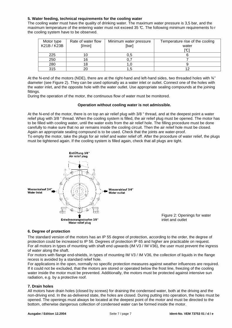
At the N-end of the motors (NDE), there are at the right-hand and left-hand sides, two threaded holes with ¾’’ diameter (see Figure 2). They can be used optionally as a water inlet or outlet. Connect one of the holes with the water inlet, and the opposite hole with the water outlet. Use appropriate sealing compounds at the joining fittings. During the operation of the motor, the continuous flow of water must be monitored.
Operation without cooling water is not admissible. At the N-end of the motor, there is on top an air relief plug with 3/8 ” thread, and at the deepest point a water relief plug with 3/8 “ thread. When the cooling system is filled, the air relief plug must be opened. The motor has to be filled with cooling water, until the water exits from the air relief hole. The filling procedure must be done carefully to make sure that no air remains inside the cooling circuit. Then the air relief hole must be closed. Again an appropriate sealing compound is to be used. Check that the joints are water-proof. To empty the motor, take the plugs for air relief and water relief off. After the procedure of water relief, the plugs must be tightened again. If the cooling system is filled again, check that all plugs are tight.
6. Degree of protection The standard version of the motors has an IP 55 degree of protection, according to the order, the degree of protection could be increased to IP 56. Degrees of protection IP 65 and higher are practicable on request. For all motors in types of mounting with shaft end upwards (IM V3 / IM V36), the user must prevent the ingress of water along the shaft. For motors with flange end-shields, in types of mounting IM V3 / IM V36, the collection of liquids in the flange recess is avoided by a standard relief hole. For applications in the open, normally no specific protection measures against weather influences are required. If it could not be excluded, that the motors are stored or operated below the frost line, freezing of the cooling water inside the motor must be prevented. Additionally, the motors must be protected against intensive sun radiation, e.g. by a protective roof. 7. Drain holes All motors have drain holes (closed by screws) for draining the condensed water, both at the driving and the non-driving end. In the as-delivered state, the holes are closed. During putting into operation, the holes must be opened. The openings must always be located at the deepest point of the motor and must be directed to the bottom, otherwise dangerous collection of condensed water can be formed inside the motor.
Figure 2: Openings for water inlet and outlet

Ausgabe / Edition 12.2004 Seite 8 / page 8 Ident-No. VEM 73753 01 / d / e
8. Aufbau der Motoren / Construction of the motors Kennzahl Code No.
Bezeichnung Designation
1.01 Lagerschild D-Seite End shield Drive-end 1.02 Lagerdeckel, D-Seite, außen Bearing cover, Drive-end, external 1.03 Lagerdeckel, D-Seite, innen Bearing cover, Drive-end, internal
1.04
Tellerfeder / Wellfeder, D-Seite, nicht bei Rollenlagern
Disc spring / wave washer, Drive-end, not for roller bear-ings
1.05 Wälzlager D-Seite Antifriction bearing, Drive-end 1.06 V-Ring D-Seite V-type rotary seal, Drive-end 1.07 Flanschlagerschild Flange end shield 1.08 Filzring D-Seite Felt ring, Drive-end 2.00 Flanschring Flange ring 2.01 Lagerschild N-Seite End shield Non-drive end 2.02 Lagerdeckel, N-Seite, außen Bearing cover, Non-drive end, external 2.03 Lagerdeckel, N-Seite, innen Bearing cover, Non-drive end, internal 2.04 Wälzlager N-Seite Antifriction bearing, Non-drive end 2.05 V-Ring N-Seite V-type rotary seal, Non-drive end 2.06 Wellfeder N-Seite (oder D-Seite) Wave washer, Non-drive end (or Drive-end) 2.08 Filzring N-Seite Felt ring, Non-drive end 2.09 Entlüftungsstopfen 3/8 “ Air relief plug 3/8 “ 2.10 Wasserablassstopfen 3/8 “ Water relief plug 3/8 “ 2.11 Verschlussstopfen ¾’’ Blind plug ¾ “ 2.12 Dichtringe 2 x Sealing rings 2 pcs. 3.01 1 Paar Motorfüße 1 pair of motor feet 3.06 Ringschraube Lifting eye bolt 4.01 Klemmenkastendeckel Terminal box cover 4.03 Dichtung Klemmenkastendeckel Terminal box cover gasket 4.05 Klemmenkastenunterteil Terminal box base 4.07 Dichtung Klemmenkastenunterteil Terminal box base gasket 4.08 Klemmenplatte Terminal plate 4.09 Kabeleinführung Cable gland 4.10 Verschlussschraube Screw plug for gland opening 4.11 Kabeleinführung für thermischen Wick-
lungsschutz Cable gland for thermal winding protection
4.12 Anschluss für therm. Wicklungsschutz Terminal for thermal winding protection 4.17 Normalienbeutel Standard parts bag 5.01 Läufer, komplett Rotor, complete 6.01 Schleuderscheibe, D-Seite Grease thrower ring, Drive-end 6.02 Schleuderscheibe, N-Seite Grease thrower ring, Non-drive end 6.03 Labyrinthbuchse, D- u. N-Seite Labyrinth gland, Drive- and Non-drive end 6.04 Leitscheibe, D-Seite Guide disc, Drive-end 6.05 Leitscheibe, N-Seite Guide disc, Non-drive end

Ausgabe / Edition 12.2004 Seite 9 / page 9 Ident-No. VEM 73753 01 / d / e
Wassergekühlter Drehstrom-Asynchronmotor / Grundaus führung K2.B (Beispiel, gelieferte Ausführung kann in Details ab weichen) Water cooled three-phase asynchronous motor / basic version K2.B (example, delivered version may differ in details)