Brushless DC-Motors Bürstenlose Gleichstrommotoren · Brushless DC-Motors Bürstenlose...
50
Brushless DC-Motors Bürstenlose Gleichstrommotoren U L ® DIN EN ISO 9001:2000 DIN EN ISO 14001 Series BG Baureihe BG advanced motion solutions
Transcript of Brushless DC-Motors Bürstenlose Gleichstrommotoren · Brushless DC-Motors Bürstenlose...
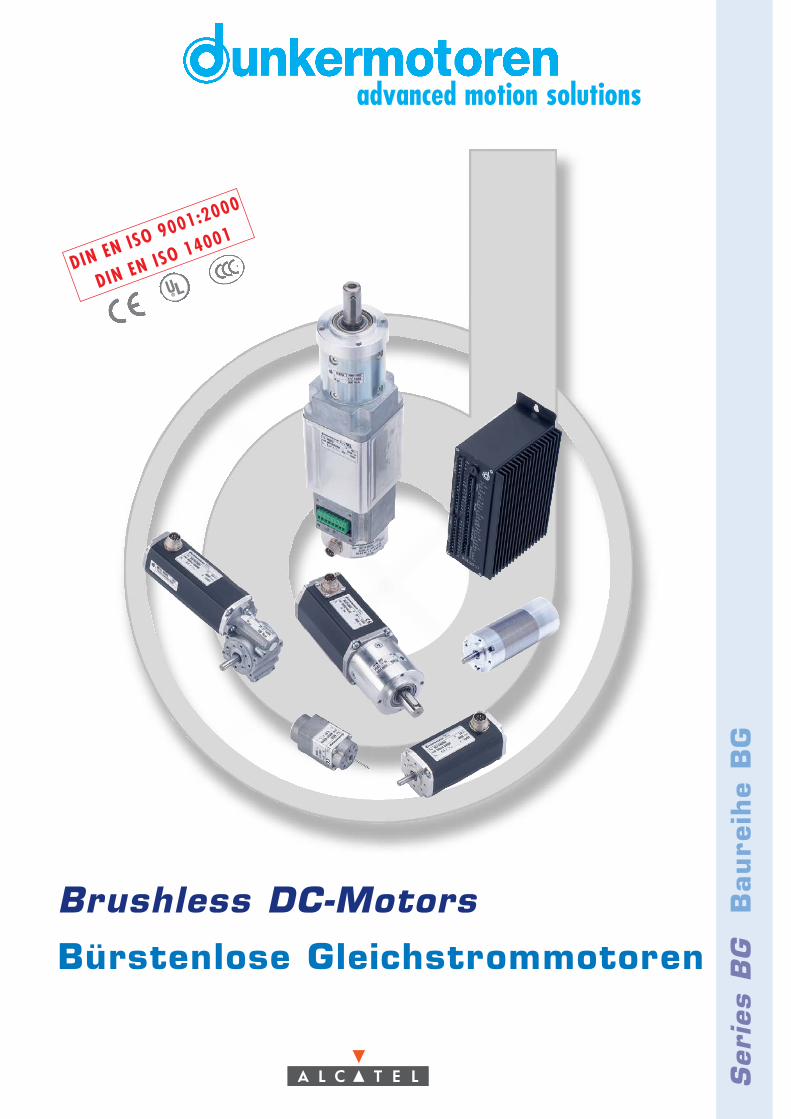
Brushless DC-Motors
Bürstenlose Gleichstrommotoren
UL®
DIN EN ISO 9001:2000
DIN EN ISO 14001
Seri
es B
GB
aure
ihe
BG
advanced motion solutions
To Our Valued Customers,
Alcatel Dunkermotoren is a world class leader inhigh quality motion control solutions to meet theever increasing demands for cost effective andreliable drive solutions.
Our comprehensive product range offers theflexibility to provide customized solutions as well asstandardized components.
The catalog represents Dunkermotoren´s years ofengineering excellence.
The Dunkermotoren Team will continue to utilizeour outstanding engineering and industrial capa-bilities to meet the requirements helping you tosucceed.
Wishing you great success in your business.
Nikolaus GräfGeneral Manager
Unseren geschätzten Kunden,
als führender Hersteller der Antriebstechnik bietetAlcatel Dunkermotoren wirtschaftliche, zuver-lässige und qualitativ hochwertige Antriebs-komplettlösungen.
Aufgrund unseres umfassenden Produktspek-trums können wir mit einem hohen Maß anFlexibilität standardisierte Komponenten sowieauch kundenspezifische Lösungen anbieten.
In diesem Katalog finden Sie eine Auswahl unsererinnovativen und richtungsweisenden Produkte.
Das Dunkermotoren-Team wird auch in Zukunft allsein Wissen und Können einbringen, um dieAnforderungen zu erfüllen, die Sie noch erfolgrei-cher machen.
Ich wünsche Ihnen weiterhin alles Gute und vielErfolg.
Nikolaus GräfGeneral Manager
VorwortForeword
Fore
word
C
onte
nt
Vorw
ort
In
halt
3
InhaltContent
Foreword / Vorwort
Content / Inhalt
Why Dunkermotoren? / Gute Gründe
Our Product Range / Unser modulares Lieferprogramm
Applications / Anwendungen
Brushless DC Motors BG / Bürstenlose Gleichstrommotoren BG
BG Selection Guide / BG-Auswahlübersicht
Technical Information / Technische Informationen
Engineering Reference / Auslegung des Antriebs
BG 31 KI, 6 W
BG 40, 15 - 30 W
BGE 40/ BGE 3004/ BGE 6007
BG 44 SI, 20 - 40 W
BG 65, 50 - 150 W
BG 65 SI, 50 - 150 W
BG 65 CI, 50 - 150 W
BG 65 KI, 60 - 220 W
BG 83, 200 - 310 W
BGE 9010
Gears / Getriebe
PLG
SG
Brakes for BLDC Motors / Bremsen für BG Motoren
Incremental Encoders for BLDC Motors / Inkrementalgeber für BG Motoren
Accessories / Zubehör
Representatives and Distributors / Vertretungen
2
3
4
6
7
8
9
10
11
12
14
16
18
20
22
24
26
28
30
31
32
36
40
42
44
50
© 11/2004
Alcatel SEL AGComponents DivisionDunkermotorenPrinted in Germany

Technology & Customer Focus
At Dunkermotoren, research and develop-ment is a way of life. The company is activelycommitted to developing key technologies andproducts that are crucial for its growth. Next-generation technology is in the R&D pipelinetoday.
Product development is focused on innovationsto help our customers create value and diffe-rentiate themselves from competitors.
Quality Assurance & Reliability
One of Dunkermotoren´s primary objectivesis to offer outstanding quality. In 1991Dunkermotoren became the world´s firstmanufacturers of small motors to becertified to ISO 9001. In the meantime,Dunkermotoren has won numerous qualityawards.Dunkermotoren regards quality as a comprehen-sive process involving all activities in the factory.Our products are manufactured exclusively inGermany on highly automated production lines.Failure mode and effects analysis during designand development, and fully automated testingintegrated in the production line ensure auniformly high level of quality.
Flexibility, Delivery Performance &Complete Motion Solutions
Standardized motors, gears and modularaccessories are available with a higher degreeof flexibility to address specific requirements incomplete motion solutions. For the customer,this means better control of quality, reducedinventory and reduced production time. If anydetail does not entirely meet your require-ments, our R&D department will make modifi-cations at short notice.
Dunkermotoren’s Modular System anoptimized logistics, enables prompt deliveryfor both stock and customized products.Delivery time for stock items are 2-5 daysand for customized solutions are 3-7 weeks.
Innovation und Kundenorientierung
Dunkermotoren ist stolz darauf, vielfach neueIndustrie-Standards in der Antriebsbranchegeschaffen zu haben. Es ist der Ansprucheines Technologieführers, der Konkurrenzimmer einen entscheidenden Schritt vorauszu sein.
Unsere innovativen marktorientierten Antriebs-lösungen machen unsere Kunden noch erfolg-reicher und helfen ihnen, sich mit ihrenProdukten positiv von denen der Mitbewerberabzusetzen.
Qualität & Zuverlässigkeit
Antriebslösungen höchster Qualität sind beiDunkermotoren eine Selbstverständlichkeit,fest verankert in Unternehmensgrundsätzenund Philosophie. Bereits 1991 wurdeDunkermotoren als weltweit erster Herstellervon Kleinmotoren nach ISO 9001 zertifiziert. Inder Zwischenzeit folgten zahlreiche weitereAuszeichnungen und Zertifizierungen vonKunden und Vereinigungen.Dunkermotoren versteht Qualität als einenganzheitlichen Prozess, der sämtliche betrieb-lichen Tätigkeiten umfasst. Dunkermotorenproduziert ausschließlich in Deutschland;hochautomatisierte Fertigungsstrecken undvollautomatische Qualitätskontrollen in denFertigungslinien gewährleisten ein konstanthohes Qualitätsniveau.
Flexibilität, Lieferperformance undumfassende Antriebslösungen
Dunkermotoren´s Produktpalette ist so aufge-baut, dass sich mit standardisierten Motorenund einem modular aufgebauten Zubehör einehohe Flexibilität für umfassende Antriebs-lösungen ergibt. Und sollten sie einmal einProdukt benötigen, dass es noch nicht gibt,dann entwickelt unsere Konstruktions-abteilung kundenspezifische Sonderlösungenin kürzester Zeit.
Aufgrund der konsequenten Verwirklichungdes Baukastensystems und einer ausgeklügel-ten Produktionslogistik bietet Dunkermotoreneine bessere Lieferperformance als diemeisten Mitbewerber, bei Lagerprodukten(Ø 2-5 Tage) wie auch bei kundenspezifischenLösungen (Ø 3-7 Wochen).
Gute Gründe
4
Why Dunkermotoren?

Service & Proximity
Whether home or abroad, Dunkermotoren´smulti-lingual customer service advisers arealways on hand. By worldwide local presenceof Alcatel Dunkermotoren individual responsi-bility is given to the interests of the tradingpartners - the best drive solution and the mosteconomical application.
Today and in the future, Dunkermotoren willprovide a total service to the customers -wherever they are.
Sustainable Development
Dunkermotoren is fully aware of its role topromote sustainable development. Thereforeit commits itself to pay particular attention tothe environment conservation while selectingand using efficiently raw materials and energynecessary for production, supply and use ofthe product.
In 2002 Dunkermotoren has introducedthe environmental management systemconforming to the standard ISO 14001.
Why
Dunkerm
oto
ren?
Gute
Grü
nde
Service & Kundennähe
Ob im In- oder Ausland, Dunkermotoren´sKundenberater sind immer vor Ort präsentund sprechen die Sprache des Kunden. Zurbestmöglichen Berücksichtigung der Interes-sen des Kunden werden individuelle Schulun-gen, Betreuung und Beratung durch unserehochkompetenten Account Manager gewähr-leistet.
In der Technik wie auch im Vertrieb –Dunkermotoren´s Mitarbeiter scheuen keineHerausforderung, Ihre Anforderungen undWünsche sind Maßstab für Denken undHandeln.
Umweltschutz und nachhaltigeEntwicklung
Dunkermotoren ist sich seiner Rolle, nachhal-tige Entwicklung zu fördern, bewusst.Deshalb hat sich die Firma dem Umweltschutzverpflichtet. Ressourcen werden sparsam undeffizient eingesetzt.
Als erster Hersteller von Elektrokleinmotorenerhielt Dunkermotoren im Jahre 2002 dieUmweltmanagementauszeichnung nach DINEN ISO 14001.
5
DarumTherefore
advanced motion solutions
Unser modulares Lieferprogramm
6
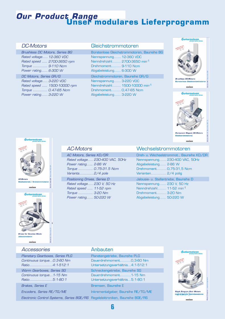
Brushless DC Motors, Series BGRated voltage.....Rated speed ......Torque .............Power rating......
12-360 VDC2700-3650 rpm9-110 Ncm6-300 W
Bürstenlose Gleichstrommotoren, Baureihe BGNennspannung.......Nenndrehzahl........Drehmoment.........Abgabeleistung......
DC Motors, Series GR/GRated voltage.....Rated speed ......Torque .............Power rating......
Gleichstrommotoren, Baureihe GR/GNennspannung.......Nenndrehzahl........Drehmoment.........Abgabeleistung......
3-220 VDC1500-10000 min-1
0,47-65 Ncm3-220 W
12-360 VDC2700-3650 min-1
9-110 Ncm6-300 W
3-220 VDC1500-10000 rpm0.47-65 Ncm3-220 W
AC Motors, Series KD/DRRated voltage.....Power rating......Torque .............Variants.............
Dreh- u. Wechselstrommot., Baureihe KD/DRNennspannung.......Abgabeleistung......Drehmoment.........Varianten..............
AC-Motors Wechselstrommotoren
Positioning Drives, Series DRated voltage.....Rated speed ......Torque .............Power rating......
Jalousie- u. Stellantriebe, Baureihe DNennspannung.......Nenndrehzahl........Drehmoment.........Abgabeleistung......
230-400 VAC, 50Hz2-86 W0.75-31.5 Ncm2/4 pole
230 V, 50 Hz11-52 rpm3-20 Nm50-220 W
230-400 VAC, 50Hz2-86 W0,75-31,5 Ncm2/4 polig
230 V, 50 Hz11-52 min-1
3-20 Nm50-220 W
Planetary Gearboxes, Series PLGContinuous torque...0.3-60 NmRatio.....................4:1-512:1
Planetengetriebe, Baureihe PLGDauerdrehmoment..........0,3-60 NmUntersetzungsverhältnis...4:1-512:1
Worm Gearboxes, Series SGContinuous torque...1-15 NmRatio.....................5:1-80:1
Brakes, Series E
Encoders, Series RE/TG/ME
Electronic Control Systems, Series BGE/RS
Schneckengetriebe, Baureihe SGDauerdrehmoment..........1-15 NmUntersetzungsverhältnis...5:1-80:1
Bremsen, Baureihe E
Inkrementalgeber, Baureihe RE/TG/ME
Regelelektroniken, Baureihe BGE/RS
AnbautenAccessories
DC-Motors Gleichstrommotoren
Our Product Range
Anwendungen
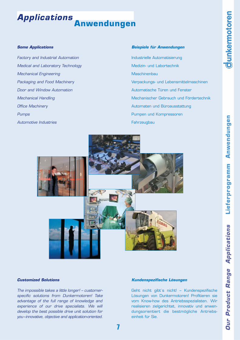
Some Applications
Factory and Industrial Automation
Medical and Laboratory Technology
Mechanical Engineering
Packaging and Food Machinery
Door and Window Automation
Mechanical Handling
Office Machinery
Pumps
Automotive Industries
Customized Solutions
The impossible takes a little longer! – customer-specific solutions from Dunkermotoren! Takeadvantage of the full range of knowledge andexperience of our drive specialists. We willdevelop the best possible drive unit solution foryou–innovative, objective and application-oriented.
Our
Pro
duct
Range
Applica
tions
Lie
ferp
rogra
mm
Anw
endungen
7
Beispiele für Anwendungen
Industrielle Automatisierung
Medizin- und Labortechnik
Maschinenbau
Verpackungs- und Lebensmittelmaschinen
Automatische Türen und Fenster
Mechanischer Gebrauch und Fördertechnik
Automaten und Büroausstattung
Pumpen und Kompressoren
Fahrzeugbau
Kundenspezifische Lösungen
Geht nicht gibt´s nicht! – KundenspezifischeLösungen von Dunkermotoren! Profitieren sievom Know-how des Antriebsspezialisten. Wirrealisieren zielgerichtet, innovativ und anwen-dungsorientiert die bestmögliche Antriebs-einheit für Sie.
Applications
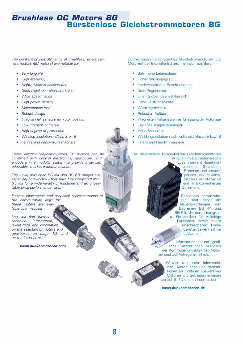
The Dunkermotoren BG range of brushless, direct cur-rent motors (EC motors) are notable for:
• Very long life
• High efficiency
• Highly dynamic acceleration
• Good regulation characteristics
• Wide speed range
• High power density
• Maintenance-free
• Robust design
• Integral Hall sensors for rotor position
• Low moment of inertia
• High degree of protection
• Winding insulation - Class E or B
• Ferrite and neodymium magnets
These electronically-commutated DC motors can becombined with control electronics, gearboxes, andencoders in a modular system to provide a flexible,adaptable, market-oriented solution.
The newly developed BG 44 and BG 65 ranges areespecially noteworthy – they have fully integrated elec-tronics for a wide variety of functions and an unbea-table price-performance ratio.
Further information and graphical representations ofthe commutation logic forthese motors are avai-lable upon request.
You will find furthertechnical information,layout data, and informationon the selection of motors andgearboxes on page 10, andon the Internet at:
www.dunkermotoren.com
Dunkermotoren´s bürstenlose Gleichstrommotoren (EC-Motoren) der Baureihe BG zeichnen sich aus durch:
• Sehr hohe Lebensdauer
• Hoher Wirkungsgrad
• Hochdynamische Beschleunigung
• Gute Regelbarkeit
• Einen großen Drehzahlbereich
• Hohe Leistungsdichte
• Wartungsfreiheit
• Robusten Aufbau
• Integrierten Hallsensoren zur Erfassung der Rotorlage
• Geringes Trägheitsmoment
• Hohe Schutzart
• Wicklungsisolation nach Isolierstoffklasse E bzw. B
• Ferrit- und Neodymmagnete
Die elektronisch kommutierten Gleichstrommotorenergeben im Baukastensystem
zusammen mit Regel-Elek-troniken, Getrieben,Bremsen und Istwert-gebern ein flexibles,anpassungsfähigesund marktorientiertesSortiment.
Besonders hervorzuhe-ben sind dabei dieNeuentwicklungen derBaureihen BG 44 und
BG 65, die durch integrier-te Elektroniken für vielfältige
Funktionen sowie einemunschlagbaren Preis-Leistungsverhältnisbestechen.
Informationen und grafi-sche Darstellungen bezüglich
der Kommutierungslogik der Moto- ren sind auf Anfrage erhältlich.
Weitere technische Informatio-nen, Auslegungen und Informa-tionen zur richtigen Auswahl vonMotoren und Getrieben erhalten
sie auf S. 10 und im Internet bei
www.dunkermotoren.de
Bürstenlose Gleichstrommotoren BG Brushless DC Motors BG
8
Standard/Standard On request/auf Anfrage
9
BG
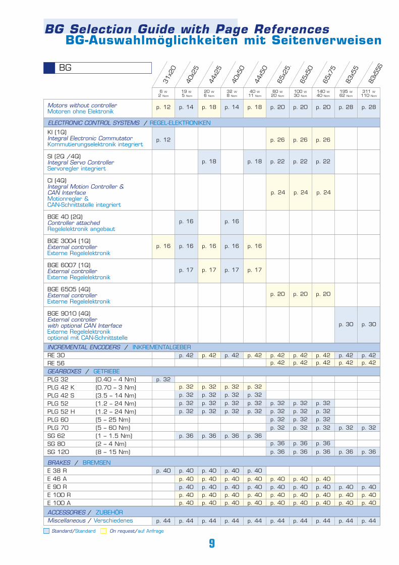
BG-Auswahlmöglichkeiten mit SeitenverweisenBG Selection Guide with Page References
31x2
0
40x2
5
44x2
5
40x5
0
44x5
0
65x2
5.
65x5
0
65x7
5
83x5
5
83x5
5S
ELECTRONIC CONTROL SYSTEMS / REGEL-ELEKTRONIKEN
KI (1Q) Integral Electronic CommutatorKommutierungselektronik integriert
SI (2Q /4Q)Integral Servo Controller Servoregler integriert
CI (4Q)Integral Motion Controller &CAN Interface Motionregler & CAN-Schnittstelle integriert
BGE 40 (2Q)Controller attachedRegelelektronik angebaut
BGE 3004 (1Q)External controllerExterne Regelelektronik
BGE 6007 (1Q)External controller Externe Regelelektronik
BGE 6505 (4Q)External controllerExterne Regelelektronik
BGE 9010 (4Q)External controllerwith optional CAN InterfaceExterne Regelelektronik optional mit CAN-Schnittstelle
INCREMENTAL ENCODERS / INKREMENTALGEBERRE 30RE 56GEARBOXES / GETRIEBEPLG 32 (0.40 – 4 Nm)PLG 42 K (0.70 – 3 Nm)PLG 42 S (3.5 – 14 Nm)PLG 52 (1.2 – 24 Nm)PLG 52 H (1.2 – 24 Nm)PLG 60 (5 – 25 Nm)PLG 70 (5 – 60 Nm)SG 62 (1 – 1.5 Nm)SG 80 (2 – 4 Nm)SG 120 (8 – 15 Nm)
BRAKES / BREMSENE 38 RE 46 AE 90 RE 100 RE 100 A
ACCESSORIES / ZUBEHÖRMiscellaneous / Verschiedenes
6 W2 Ncm
19 W5 Ncm
20 W6 Ncm
32 W8 Ncm
40 W11 Ncm
60 W20 Ncm
100 W30 Ncm
140 W40 Ncm
195 W62 Ncm
311 W110 Ncm
p. 12
p. 18 p. 18 p. 22 p. 22
p. 24 p. 24 p. 24
p. 16
p. 16 p. 16 p. 16 p. 16 p. 16
p. 17 p. 17 p. 17 p. 17
p. 20 p. 20 p. 20
p. 30 p. 30
p. 12 p. 14
p. 42 p. 42 p. 42 p. 42p. 42 p. 42 p. 42 p. 42 p. 42p. 42 p. 42 p. 42 p. 42 p. 42
p. 18 p. 14 p. 18 p. 20 p. 20 p. 20 p. 28 p. 28
p. 16
p. 22
p. 26 p. 26 p. 26
p. 32
p. 40 p. 40 p. 40 p. 40 p. 40
p. 36 p. 36 p. 36 p. 36
p. 36 p. 36 p. 36 p. 36 p. 36
p. 36 p. 36 p. 36
p. 32 p. 32 p. 32 p. 32 p. 32 p. 32 p. 32p. 32 p. 32 p. 32 p. 32p. 32 p. 32 p. 32 p. 32
p. 32 p. 32 p. 32 p. 32 p. 32 p. 32 p. 32p. 32 p. 32 p. 32p. 32 p. 32 p. 32 p. 32 p. 32
p. 40 p. 40 p. 40 p. 40 p. 40 p. 40 p. 40p. 40 p. 40 p. 40 p. 40 p. 40 p. 40 p. 40 p. 40 p. 40p. 40 p. 40 p. 40 p. 40 p. 40 p. 40 p. 40 p. 40 p. 40p. 40 p. 40 p. 40 p. 40 p. 40 p. 40 p. 40 p. 40 p. 40
p. 44 p. 44 p. 44 p. 44 p. 44 p. 44 p. 44 p. 44 p. 44 p. 44
Motors without controllerMotoren ohne Elektronik
10
Technische Information
PERFORMANCE DATA
Performance figures given in the tables are measured in accordancewith VDE530/ EN60034. These figures are based on the assumptionthat the motor is freestanding and that certain other theoreticalconditions are fulfilled. In a real application, the rated torque of amotor will often be considerably higher. For this reason, the datatables quote the rated torquemeasured according to VDE/ EN(lower value) and also the torquewith the motor mounted on athermally conducting steel platewith the dimensions 105 x 105 x10 mm (value in brackets).
For many applications, it is suffi-ciently accurate to take the mostimportant data from the motorcharacteristic diagrams and datatables. Although tolerances andtemperature influences are nottaken into account, the data isaccurate enough for approximatecalculations. The degree ofprotection quoted relates only to the housing – adequate sealing of theshaft is the responsibility of the customer.
- Nominal voltage UN (VDC) The DC voltage that is applied to the commutation electronics asa system supply voltage. All rated data in our catalogs are withreference to this voltage. Motor applications are, however, notrestricted to this voltage.
- Rated torque MN (Ncm)The torque that can be produced by the motor, operating con-tinuously, in an ambient temperature of 20°C.
- Rated speed nN (min-1)The speed of the motor when it is operating at rated torque (6).
- Rated current IN (A)The current drawn from a DC source when the motor is operatingat rated torque (7).
- Starting current IA (A)The current required to produce the starting torque. For motorswith electronics, the starting current may be higher than thepermissible peak current (4).
- Starting torque MA (Ncm)The maximum torque the motor can produce (2).
- Rated power PN (W)The output power which the motor can produce continuously; it iscalculated from rated speed and rated torque.
- Moment of inertia of rotor JR (gcm2)The moment of inertia of the rotor is the factor that determines thedynamic properties of a motor.
- Peak current Imax (A)The maximum current for electronics or motors with integralelectronics (5).
- Max. permissible voltage range Umax (VDC)The minimum and maximum permissible input voltage forelec- tronics or motors with integral electronics.
- Recommended speed control range nmax (min-1)The regulated speed range within which rotor position sensing byHall sensors ensures a smooth torque curve. As a rule, this rangecan be extended by installing a rotary encoder.
The data in this catalog contain product specifications, but are not aguarantee of particular properties. The stated values are subject totolerances. Any supplementary information and safety instructionsgiven in the operating manual must be observed with no exceptions.We reserve the right to make technical changes and to restrictavailability.
LEISTUNGSDATEN
In den Datentabellen sind die Werte gemessen nach VDE530/EN60034 angegeben. Diese Werte basieren auf der Annahmeeines freistehenden Motors und auf weiteren theoretischenGegebenheiten. Im reellen Einsatzfall liegt das Nenndrehmomentdes Motors oftmals wesentlich höher. Deshalb sind in den Daten-
tabellen die Nenndrehmomen-te gemessen nach VDE/ EN(niedrigere Angabe) sowiegemessen bei Anbringungeiner thermisch leitendenStahlplatte der Größe 105 x105 x 10 mm (Angabe inKlammern) aufgeführt.
Den Motordiagrammen undDatentabellen können die fürviele Anwendungen wichtig-sten Daten entnommen wer-den. Obwohl Toleranzen undTemperatureinflüsse nichtberücksichtigt sind, reichen dieWerte für überschlagsmässige
Betrachtungen aus. Die angegebenen Schutzarten beziehen sich nur aufdie Gehäuse. Die Abdichtung der Welle ist vom Kunden vorzunehmen.
- Nennspannung UN (VDC) Die Gleichspannung, die als Systemversorgungsspannung an dieKommutierungselektronik angelegt wird. Auf diese Spannung bezie-hen sich alle Nenndaten in den Katalogen. Die Motoranwendung istjedoch nicht auf diese Spannung beschränkt.
- Nenndrehmoment MN (Ncm)Das Moment, das der Motor bei einer Umgebungstemperatur von20°C im Dauerbetrieb abgeben kann.
- Nenndrehzahl nN (min-1)Die Drehzahl, die sich bei Abgabe des Nenndrehmoments einstellt (6).
- Nennstrom IN (A)Der Strom, der der Gleichspannungsquelle entnommen wird, wennder Motor bei Nenndrehmoment betrieben wird (7).
- Anlaufstrom IA (A)Der Strom, der fließt, um das Anlaufmoment zu erzeugen. BeiMotoren mit Elektronik kann der Anlaufstrom höher sein als derzulässige Spitzenstrom (4).
- Anlaufmoment MA (Ncm)Das Moment, welches der Motor maximal erzeugen kann (2).
- Nennleistung PN (W)Die Abgabeleistung des Motors, welche er dauerhaft erzeugenkann; berechnet aus Nenndrehzahl und Nenndrehmoment.
- Läufermassenträgheitsmoment JR (gcm2)Massenträgheitsmoment des Rotors und bestimmende Größe fürdie dynamischen Eigenschaften des Motors.
- Spitzenstrom Imax (A)Der maximal zulässige Strom bei Elektroniken oder Motoren mitintegrierter Elektronik (5).
- Max. zulässiger Spannungsbereich Umax (VDC)Die minimal und maximal zulässige Eingangsspannung beiElektroniken oder Motoren mit integrierter Elektronik.
- Empfohlener Drehzahlregelbereich nmax (min-1)Der Drehzahlregelbereich in dem bei Rotorlageerkennung durchHallsensoren ein glatter Drehmomentverlauf steuerbar ist. DurchAnbringung eines Inkrementalencoders kann dieser Bereich in derRegel erweitert werden.
Die Angaben in diesem Katalog enthalten Spezifikationen derProdukte, nicht aber die Zusicherung von Eigenschaften. Die genann-ten Werte unterliegen Toleranzen. Die im Betriebshandbuch angege-benen Ergänzungen und Sicherheitshinweise sind unbedingt zu beachten.Liefermöglichkeiten und technische Änderungen vorbehalten.
Technical Information
N = f (M)
Destroying operationZerstörende Betriebszuständeη
-0.8 0 0.8 1.6 2.4 3.2 4 4.8 5.6 6.4 7.2 8 Ncm
curre
nt/S
trom
I (A)
2.8
2.4
2
1.6
1.2
0.8
0.4
0
70
60
50
40
30
20
10
0effic
iency
/Wirk
ungs
grad
η (%
)
rated
spee
d/Dr
ehza
hl n
(rpm)
7000
6000
5000
4000
3000
2000
1000
0
J = f (M)
MN
Continuous operationDauerbetrieb
Cyclic operationZyklischer Betrieb
11 Tech
nic
al
Info
rmati
on
Tech
nis
che
Info
rmati
onen
Engineering ReferenceAuslegung des Antriebs
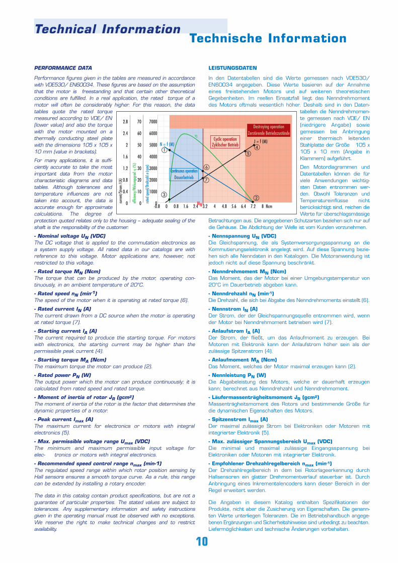
MOTOR CHARACTERISTIC DIAGRAMS
- Speed curve (blue)This curve shows the speed characteristic at constant voltage. Itsend points are the no-load speed n0 (1) and the theoretical startingtorque MA (2).
- Current curve (black)The current curve shows the relationship between current andtorque. Its end points are the no-load current I0 (3) and the startingcurrent IA (4).
- Efficiency curve (green)The efficiency is the relationship between the mechanical power out-put and the electrical power input.The curve shows the efficiency with the motor in cold condition; asthe motor warms up, the curve shifts accordingly.
- Rated torque MN/ Starting torque MmaxThe rated torque (red) is the limit of the continuous operationregion (shaded blue). In the region between the rated torque andthe maximum permissible torque, the motor must only be usedintermittently (shaded orange). Operating conditions above the maxi-mum permissible torque result in demagnetization of the permanentmagnets (shaded red).
ENGINEERING REFERENCE
In the wide range of Dunkermotoren products, you will find a suita-ble drive for almost any requirement in powers ranging from 1 –310 Watt. Please note also our other product lines and catalogs(DC commutator motors, AC motors).
The following points should be taken into account when selectingmotors and gearboxes:
- Which type of operation is required (continuous, intermittent orperiodic operation)?
- What is the working life expected of the motor?- What torque and speeds are required?- How much space is available for the motor?- How high is the available voltage? DC or AC?- Are there special environmental conditions (temperature,
humidity, vibration, ...)? - To what degree can heat from the motor be disposed of?- Are there exceptional axial and radial shaft loads to consider?- What demands are made of the motor control electronics?- Is the motor to be controlled online via a bus system?- Do you need a brake, an encoder or a non-reversing device?
When laying out a suitable motor, determining the required torqueplays a decisive role in avoiding thermal overload of the motor in ser-vice. In the assembly of a drive system consisting of motor and con-trol electronics, it is important to ensure that permissible values forthe motor are not exceeded by outputs from the electronics.
Depending on the speed of rotation required, a motor or a motor-gearbox combination may be selected. The choice of a reductiongearbox will largely depend on the recommended maximum torquein continuous operation. For intermittent duty, loading above therated torque is possible. When choosing a motor after deciding on the gearbox, the followingapplies:
Mmotor = Mgearbox / (i x η)
We will be pleased to carry out a precise adaptation of a motor toyour service conditions.
MOTORDIAGRAMME
- Drehzahlkennlinie (blau)Diese Kennlinie beschreibt das Drehzahlverhalten bei konstanterSpannung. Deren Endpunkte zeigen die Leerlaufdrehzahl n0 (1) unddas theoretische Anlaufmoment MA (2).
- Stromkennlinie (schwarz)Die Stromkennlinie stellt die Äquivalenz von Strom und Drehmomentdar. Deren Endpunkte zeigen den Leerlaufstrom I0 (3) und denAnlaufstrom IA (4).
- Wirkungsgradkennlinie (grün)Der Wirkungsgrad beschreibt das Verhältnis von abgegebenermechanischer Leistung zu aufgenommener elektrischer Leistung.Die Kennlinien beziehen sich auf den Kaltzustand des Motors undverschieben sich entsprechend bei zunehmender Erwärmung desMotors.
- Nenndrehmoment MN, Anlaufdrehmoment MmaxDas Kriterium Nenndrehmoment (rot) begrenzt den Dauerbetriebs-bereich (blau schattiert). Im Bereich zwischen Nenndrehmomentund max. zulässigem Drehmoment darf der Motor nur kurzzeitigbetrieben werden (orange schattiert). Betriebszustände über demmax. zulässigen Drehmoment führen zur Entmagnetisierung derDauermagneten (rot schattiert).
AUSLEGUNG DES ANTRIEBS
In Dunkermotoren´s breiter Produktpalette finden Sie für nahezujede Anforderung einen passenden Antrieb im Leistungsbereich von1 – 310 Watt. Bitte beachten Sie auch unsere weiterenProduktlinien und –kataloge (DC Kollektormotoren, Wechselstrom-motoren).
Folgende Punkte sollten bei der Auswahl von Motor und Getriebeberücksichtigt werden:
- Welche Betriebsart liegt vor (Dauer-, Kurzzeit- oder Aussetzbetrieb)?
- Welche Lebensdauer wird gefordert?- Welches Drehmoment und welche Drehzahl werden benötigt?- Wie viel Raum ist für den Motor verfügbar?- Wie hoch ist die verfügbare Spannung? Gleich- oder
Wechselspannung?- Gibt es besondere Umgebungseinflüsse (Temperatur,
Feuchtigkeit, Vibration, ...)? - In welchem Umfang wird die Motorwärme abgeleitet?- Müssen außergewöhnliche axiale und radiale Wellenbelastungen
berücksichtigt werden?- Welchen Steuerungsanforderungen muss die
Steuerungselektronik des Motors genügen?- Werden die Motoren online über ein Bussystem angesteuert?- Benötigen Sie eine Bremse, einen Encoder oder eine
Rücklaufsperre?
Für die Auslegung des geeigneten Motors spielt die Ermittlung deseffektiven Drehmomentes die entscheidende Rolle, um zuverhindern, dass der Motor im Betrieb thermisch überlastet wird.Für die Zusammenstellung eines Antriebssystems aus Motor undBetriebselektronik ist zu berücksichtigen, dass die für den Motorzulässigen Werte durch die Elektronik nicht überschritten werden.
Je nach gewünschter Drehzahl wird man sich für entweder für einenMotor oder einen Getriebemotor entscheiden. Die Wahl desUntersetzungsgetriebes richtet sich nach dem empfohlenen maxi-malen Drehmoment bei Dauerbetrieb. Bei kurzzeitigem Betrieb sindauch Belastungen über dem Nennmoment möglich. Zur Auswahl des Motors nach Festlegung des Getriebes gilt:
MMotor = MGetriebe / (i x η)
Gerne erfolgt auf Aufrage eine exakte Anpassung des Motors anIhre Betriebsbedingungen.

12-
163140
P./S.Versions of BG 31 / Ausführungen BG 31
• Highly dynamic 3-phase EC motor• With integral commutation electronics as standard• Fitted with 4-pole neodymium magnet and preset direction
of rotation (cw or ccw)• Reverse-pole protection is incorporated as standard• In combination with BGE 3004 control
electronics, can be controlled in both directions of rotation
• The standard version has leads. In combi-nation with Electronics BGE 3004, an 8-pin socket can be provided on the motorfor supply and control purposes
• Hochdynamischer 3-strängiger EC-Motor• Standardmäßig mit integrierter Kommutierungselektronik• Mit 4-poligem Neodymmagnet werksseitig für rechtslauf (cw)
voreingestellt. Kann auf Wunsch auch für linkslauf (ccw) voreingestellt werden
• Der Verpolschutz ist serienmäßig eingebaut• In Kombination mit der Regelelektronik
BGE 3004 in beide Drehrichtungen ansteuerbar
• Die Litzenausführung ist Standard. In Kombination mit der Elektronik BGE 3004 erfolgt die Ansteuerung über einen 8-poligenMotorstecker
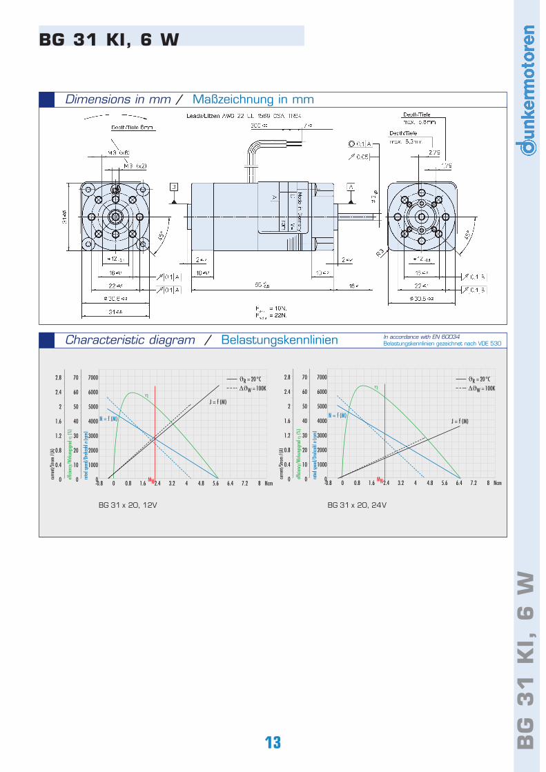
BG 31 KI, 6 W
Controllers / Regelelektroniken- integral electronic commutator / mit integrierter Kommutierungselektronik- motor without controller / Motor ohne Elektronik- with external controller (BGE3004) / mit externer Steuerungselektronik (BGE3004)
With gearbox / Als GetriebemotorWith brake / Als Bremsmotor
Standard/Standard On request/auf Anfrage
2300
2.3 (2.9*** )
1.14
5.8
2.56
9.7
0.22
7 ... 28
BG 31x20 KIData / LeistungsdatenRated voltage/Nennspannung Continuous rated speed/NenndrehzahlContinuous rated torque/NenndrehmomentContinuous current/NennstromStarting torque/Anlaufmoment Peak current/Max. zulässiger SpitzenstromRotor inertia/Trägheitsmoment Weight of motor/MotorgewichtVoltage range/Max. zulässiger Spannungsbereich
rpm*)
Ncm*)
A*)
Ncm**)
A**)
gcm2
kg
VDC
2480
2.3 (2.9*** )
0.6
6.45
1.44
9.7
0.22
7 ... 28
12 VDC 24 VDC
ELECTRONIC
INTEGRATED
*)∆ϑw =100 K; **) ϑR = 20°C;***) Continuous rated torque depends on heat dissipation from the motor (see p. 10)Das Nenndrehmoment ist abhänig von der Wärmeabführung des Motors (siehe S. 10)
12
BG
31
KI,
6 W
BG 31 x 20, 12V
Characteristic diagram / Belastungskennlinien
Dimensions in mm / Maßzeichnung in mm
BG 31 KI, 6 W
BG 31 x 20, 24V
In accordance with EN 60034Belastungskennlinien gezeichnet nach VDE 530
-0.8 0 0.8 1.6 2.4 3.2 4 4.8 5.6 6.4 7.2 8 Ncm
7000
6000
5000
4000
3000
2000
1000
0
70
60
50
40
30
20
10
0
2.8
2.4
2
1.6
1.2
0.8
0.4
0 rated
spee
d/Dr
ehza
hl n
(rpm)
effic
iency
/Wirk
ungs
grad
η (%
)
curre
nt/S
trom
I (A)
MN
N = f (M)
J = f (M)η
-0.8 0 0.8 1.6 2.4 3.2 4 4.8 5.6 6.4 7.2 8 Ncm
7000
6000
5000
4000
3000
2000
1000
0
70
60
50
40
30
20
10
0
2.8
2.4
2
1.6
1.2
0.8
0.4
0 rated
spee
d/Dr
ehza
hl n
(rpm)
effic
iency
/Wirk
ungs
grad
η (%
)
curre
nt/S
trom
I (A)
MN
N = f (M)J = f (M)
ηϑR = 20°C
∆ϑW = 100K
ϑR = 20°C
∆ϑW = 100K
13
141616
423140
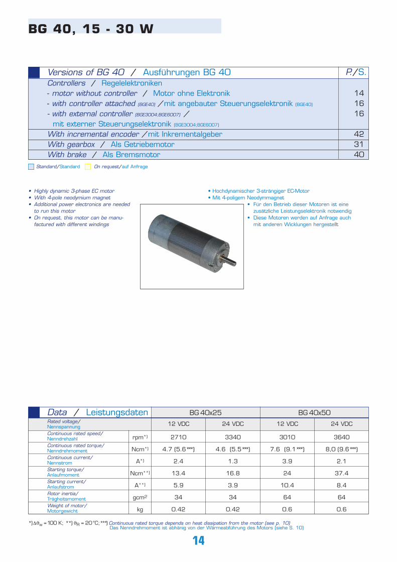
P./S.Versions of BG 40 / Ausführungen BG 40
14
BG 40, 15 - 30 W
• Highly dynamic 3-phase EC motor• With 4-pole neodymium magnet• Additional power electronics are needed
to run this motor• On request, this motor can be manu-
factured with different windings
• Hochdynamischer 3-strängiger EC-Motor• Mit 4-poligem Neodymmagnet
• Für den Betrieb dieser Motoren ist eine zusätzliche Leistungselektronik notwendig
• Diese Motoren werden auf Anfrage auch mit anderen Wicklungen hergestellt
Controllers / Regelelektroniken- motor without controller / Motor ohne Elektronik- with controller attached (BGE40) /mit angebauter Steuerungselektronik (BGE40)
- with external controller (BGE3004;BGE6007) /mit externer Steuerungselektronik (BGE3004;BGE6007)
With incremental encoder /mit InkrementalgeberWith gearbox / Als GetriebemotorWith brake / Als Bremsmotor
Standard/Standard On request/auf Anfrage
12 VDC
2710
4.7 (5.6*** )
2.4
13.4
5.9
34
0.42
BG 40x25 BG 40x50Data / LeistungsdatenRated voltage/Nennspannung Continuous rated speed/NenndrehzahlContinuous rated torque/NenndrehmomentContinuous current/NennstromStarting torque/Anlaufmoment Starting current/AnlaufstromRotor inertia/Trägheitsmoment Weight of motor/Motorgewicht
rpm*)
Ncm*)
A*)
Ncm**)
A**)
gcm2
kg
24 VDC
3340
4.6 (5.5*** )
1.3
16.8
3.9
34
0.42
12 VDC
3010
7.6 (9.1*** )
3.9
24
10.4
64
0.6
24 VDC
3640
8,0 (9.6*** )
2.1
37.4
8.4
64
0.6
*)∆ϑw =100 K; **) ϑR = 20°C;***) Continuous rated torque depends on heat dissipation from the motor (see p. 10)Das Nenndrehmoment ist abhänig von der Wärmeabführung des Motors (siehe S. 10)
15 BG
40
, 1
5 -
30
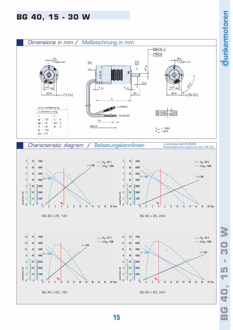
WBG 40 x 25, 12V
Characteristic diagram / Belastungskennlinien
BG 40, 15 - 30 W
BG 40 x 25, 24V
BG 40 x 50, 12V BG 40 x 50, 24V
In accordance with EN 60034Belastungskennlinien gezeichnet nach VDE 530
Dimensions in mm / Maßzeichnung in mm
-2 0 2 4 6 8 10 12 14 16 18 20 Ncm
7000
6000
5000
4000
3000
2000
1000
0
70
60
50
40
30
20
10
0
7
6
5
4
3
2
1
0 rated
spee
d/Dr
ehza
hl n
(rpm)
effic
iency
/Wirk
ungs
grad
η (%
)
curre
nt/S
trom
I (A)
MN
N = f (M)
J = f (M)
η
-2 0 2 4 6 8 10 12 14 16 18 20 Ncm
7000
6000
5000
4000
3000
2000
1000
0
70
60
50
40
30
20
10
0
7
6
5
4
3
2
1
0 rated
spee
d/Dr
ehza
hl n
(rpm)
effic
iency
/Wirk
ungs
grad
η (%
)
curre
nt/S
trom
I (A)
MN
N = f (M) J = f (M)η
-4 0 4 8 12 16 20 24 28 32 36 40 Ncm
7000
6000
5000
4000
3000
2000
1000
0
70
60
50
40
30
20
10
0
14
12
10
8
6
4
2
0 rated
spee
d/Dr
ehza
hl n
(rpm)
effic
iency
/Wirk
ungs
grad
η (%
)
curre
nt/S
trom
I (A)
MN
N = f (M)
J = f (M)
η
-4 0 4 8 12 16 20 24 28 32 36 40 Ncm
7000
6000
5000
4000
3000
2000
1000
0
70
60
50
40
30
20
10
0
14
12
10
8
6
4
2
0 rated
spee
d/Dr
ehza
hl n
(rpm)
effic
iency
/Wirk
ungs
grad
η (%
)
curre
nt/S
trom
I (A)
N = f (M) J = f (M)η
ϑR = 20°C
∆ϑW = 100K
ϑR = 20°C
∆ϑW = 100K
ϑR = 20°C
∆ϑW = 100K
ϑR = 20°C
∆ϑW = 100K
MN
16
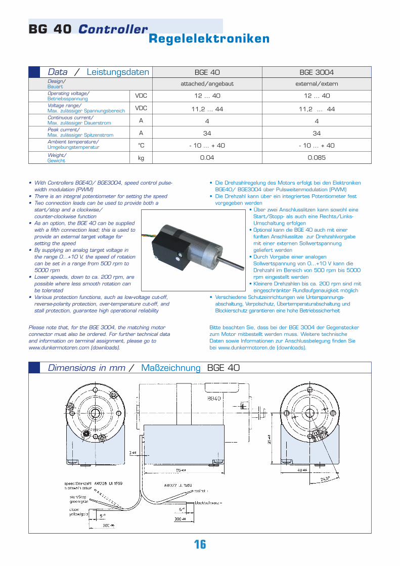
attached/angebaut
12 ... 40
11,2 ... 44
4
34
- 10 ... + 40
0.04
BGE 40
external/extern
12 ... 40
11,2 ... 44
4
34
- 10 ... + 40
0.085
BGE 3004Data / LeistungsdatenDesign/BauartOperating voltage/Betriebsspannung Voltage range/Max. zulässiger SpannungsbereichContinuous current/Max. zulässiger Dauerstrom Peak current/Max. zulässiger SpitzenstromAmbient temperature/Umgebungstemperatur
Weight/Gewicht
VDC
VDC
A
A
°C
kg
• Die Drehzahlregelung des Motors erfolgt bei den ElektronikenBGE40/ BGE3004 über Pulsweitenmodulation (PWM)
• Die Drehzahl kann über ein integriertes Potentiometer fest vorgegeben werden
• Über zwei Anschlusslitzen kann sowohl eine Start/Stopp- als auch eine Rechts/Links-Umschaltung erfolgen
• Optional kann die BGE 40 auch mit einer fünften Anschlusslitze zur Drehzahlvorgabe mit einer externen Sollwertspannung geliefert werden
• Durch Vorgabe einer analogen Sollwertspannung von 0...+10 V kann die Drehzahl im Bereich von 500 rpm bis 5000rpm eingestellt werden
• Kleinere Drehzahlen bis ca. 200 rpm sind miteingeschränkter Rundlaufgenauigkeit möglich
• Verschiedene Schutzeinrichtungen wie Unterspannungs-abschaltung, Verpolschutz, Übertemperaturabschaltung und Blockierschutz garantieren eine hohe Betriebssicherheit
Bitte beachten Sie, dass bei der BGE 3004 der Gegensteckerzum Motor mitbestellt werden muss. Weitere technischeDaten sowie Informationen zur Anschlussbelegung finden Siebei www.dunkermotoren.de (downloads).
• With Controllers BGE40/ BGE3004, speed control pulse-width modulation (PWM)
• There is an integral potentiometer for setting the speed• Two connection leads can be used to provide both a
start/stop and a clockwise/counter-clockwise function
• As an option, the BGE 40 can be supplied with a fifth connection lead; this is used to provide an external target voltage for setting the speed
• By supplying an analog target voltage in the range 0...+10 V, the speed of rotation can be set in a range from 500 rpm to 5000 rpm
• Lower speeds, down to ca. 200 rpm, are possible where less smooth rotation can be tolerated
• Various protection functions, such as low-voltage cut-off, reverse-polarity protection, over-temperature cut-off, and stall protection, guarantee high operational reliability
Please note that, for the BGE 3004, the matching motorconnector must also be ordered. For further technical dataand information on terminal assignment, please go to www.dunkermotoren.com (downloads).
BG 40 ControllerRegelelektroniken
Dimensions in mm / Maßzeichnung BGE 40
17 BG
E 4
0,
BG
E 3
00
4,
BG
E 6
00
7
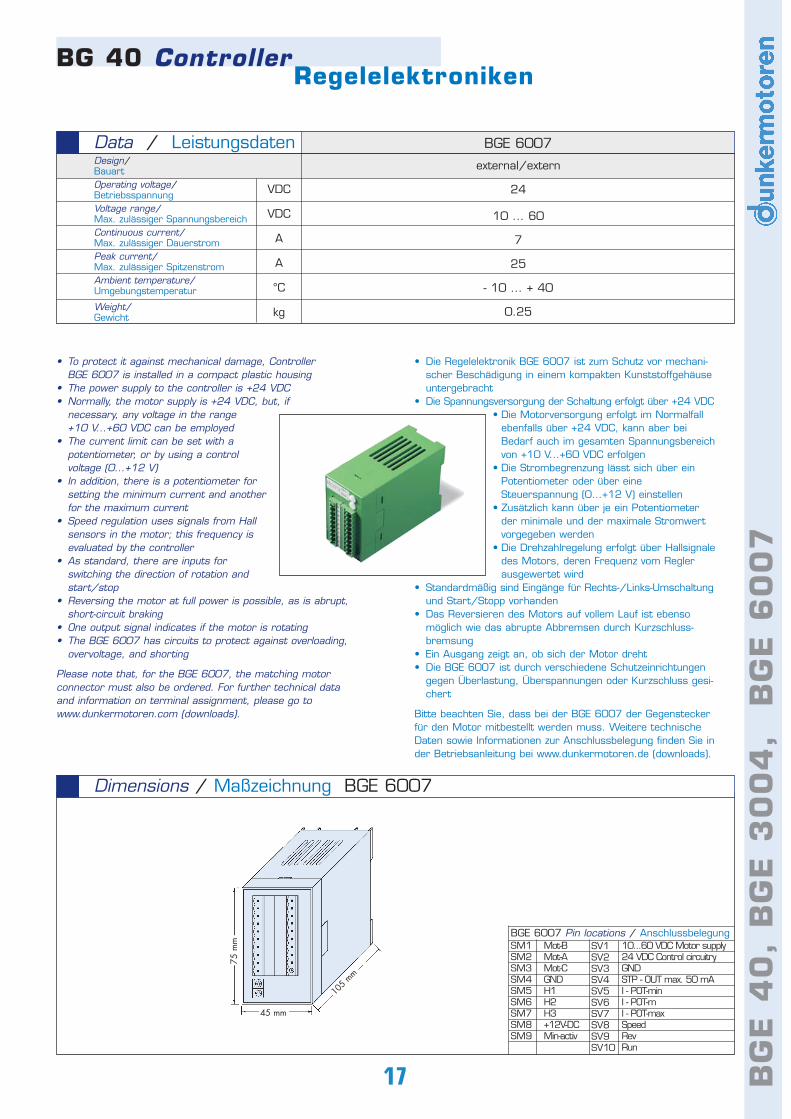
• To protect it against mechanical damage, Controller BGE 6007 is installed in a compact plastic housing
• The power supply to the controller is +24 VDC• Normally, the motor supply is +24 VDC, but, if
necessary, any voltage in the range +10 V...+60 VDC can be employed
• The current limit can be set with a potentiometer, or by using a control voltage (0...+12 V)
• In addition, there is a potentiometer for setting the minimum current and another for the maximum current
• Speed regulation uses signals from Hall sensors in the motor; this frequency is evaluated by the controller
• As standard, there are inputs for switching the direction of rotation and start/stop
• Reversing the motor at full power is possible, as is abrupt, short-circuit braking
• One output signal indicates if the motor is rotating • The BGE 6007 has circuits to protect against overloading,
overvoltage, and shorting
Please note that, for the BGE 6007, the matching motorconnector must also be ordered. For further technical dataand information on terminal assignment, please go towww.dunkermotoren.com (downloads).
• Die Regelelektronik BGE 6007 ist zum Schutz vor mechani-scher Beschädigung in einem kompakten Kunststoffgehäuse untergebracht
• Die Spannungsversorgung der Schaltung erfolgt über +24 VDC• Die Motorversorgung erfolgt im Normalfall
ebenfalls über +24 VDC, kann aber bei Bedarf auch im gesamten Spannungsbereichvon +10 V...+60 VDC erfolgen
• Die Strombegrenzung lässt sich über ein Potentiometer oder über eine Steuerspannung (0...+12 V) einstellen
• Zusätzlich kann über je ein Potentiometer der minimale und der maximale Stromwert vorgegeben werden
• Die Drehzahlregelung erfolgt über Hallsignaledes Motors, deren Frequenz vom Regler ausgewertet wird
• Standardmäßig sind Eingänge für Rechts-/Links-Umschaltungund Start/Stopp vorhanden
• Das Reversieren des Motors auf vollem Lauf ist ebenso möglich wie das abrupte Abbremsen durch Kurzschluss-bremsung
• Ein Ausgang zeigt an, ob sich der Motor dreht • Die BGE 6007 ist durch verschiedene Schutzeinrichtungen
gegen Überlastung, Überspannungen oder Kurzschluss gesi-chert
Bitte beachten Sie, dass bei der BGE 6007 der Gegensteckerfür den Motor mitbestellt werden muss. Weitere technischeDaten sowie Informationen zur Anschlussbelegung finden Sie inder Betriebsanleitung bei www.dunkermotoren.de (downloads).
Dimensions / Maßzeichnung BGE 6007
45 mm
105
mm
75 m
m
BG 40 ControllerRegelelektroniken
external/extern
24
10 ... 60
7
25
- 10 ... + 40
0.25
BGE 6007Data / LeistungsdatenDesign/BauartOperating voltage/Betriebsspannung Voltage range/Max. zulässiger SpannungsbereichContinuous current/Max. zulässiger Dauerstrom Peak current/Max. zulässiger SpitzenstromAmbient temperature/Umgebungstemperatur
Weight/Gewicht
VDC
VDC
A
A
°C
kg
BGE 6007 Pin locations / AnschlussbelegungSM1SM2SM3SM4SM5SM6SM7SM8SM9
Mot-BMot-AMot-CGNDH1H2H3+12V-DCMin-activ
SV1SV2SV3SV4SV5SV6SV7SV8SV9SV10
10...60 VDC Motor supply24 VDC Control circuitryGNDSTP - OUT max. 50 mAI - POT-minI - POT-mI - POT-maxSpeedRevRun
18
BG 44 SI, 20 - 40 W
Controllers / Regelelektroniken- integral 2Q controller (BG44SI) / mit integrierter 2Q-Steuerungselektronik (BG44SI)
- with external 2Q controller (BGE3004, BGE6007) / mit externer 2Q-Steuerungselektronik (BGE3004, BGE6007)
- motor without controller / Motor ohne Elektronik With gearbox / Als GetriebemotorWith brake / Als Bremsmotor
Versions of BG 44 / Ausführungen BG 44 P./S.
1816
-3140
• Hochdynamische 3-strängige EC-Motoren mit 4-poligem Neodymmagnet
• Mit integrierter Drehzahlregelelektronik für 2-Quadrantenbetrieb• Die Drehzahlsollwertvorgabe erfolgt standardmäßig über
einen Analogspannungseingang 0...+10V• Über zwei weitere digitale Eingänge lassen
sich die Drehrichtung rechts und links sowie Start/Stopp ansteuern
• Außerdem werden zwei digitale Ausgänge herausgeführt, womit ein Pulsausgang mit 12 Impulsen pro Umdrehung (z.B. für Positions- und Geschwindigkeitsüberwachung)und eine Fehlermeldung zur Verfügung stehen
• Kundenspezifische Ausführungen mit spezieller Steckerbelegung oder Sonderwicklungen zur Anpassung des Arbeitspunktes an die Betriebs-spannung sind auf Anfrage möglich
• Durch sein komplett geschlossenes Gehäuse aus schwarz eloxiertem Aluminium kann der Motor auf Wunsch mit Schutzart IP 65 geliefert werden
• Die hohe Leistungsdichte und kompakte Bauform gestattet bei einem günstigen Preis/Leistungsverhältnis den Einsatz inzahlreichen Anwendungen
Weitere technische Daten sowie Informationen zur Anschluss-belegung finden Sie in der Betriebsanleitung bei www.dunkermotoren.de (downloads).
Standard/Standard On request/auf Anfrage
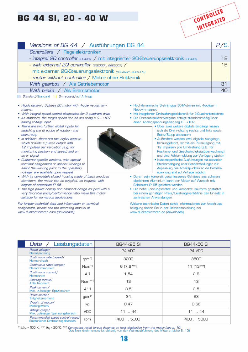
• Highly dynamic 3-phase EC motor with 4-pole neodymium magnet
• With integral speed-control electronics for 2-quadrant drive• As standard, the target speed can be set using a 0...+10V
analog voltage input• There are two further digital inputs for
switching the direction of rotation and start/stop
• In addition, there are two digital outputs, which provide a pulsed output with 12 impulses per revolution (e.g. for monitoring position and speed) and an error signal
• Customer-specific versions, with special terminal assignment or special windings toadapt the working point to the operating voltage, are available upon request
• With its completely closed housing made of black anodized aluminum, the motor can be supplied, on request, with degree of protection IP 65
• The high power density and compact design coupled with a very favorable price/performance ratio make this motor suitable for numerous applications
For further technical data and information on terminalassignment, please see the operating manual at www.dunkermotoren.com (downloads).
CONTROLLER
INTEGRATED
BG44x25 SI BG44x50 SIData / LeistungsdatenRated voltage/Nennspannung Continuous rated speed/NenndrehzahlContinuous rated torque/NenndrehmomentContinuous current/NennstromStarting torque/Anlaufmoment Peak current/Max. zulässiger SpitzenstromRotor inertia/Trägheitsmoment Weight of motor/Motorgewicht Voltage range/Max. zulässiger SpannungsbereichRecommended speed control range/Empfohlener Drehzahlregelbereich
3500
11 (13*** )
2.8
13
3.5
63
0.66
11 ... 44
400 ... 5000
24 VDC 24 VDC
*)∆ϑw =100 K; **) ϑR = 20°C;***) Continuous rated torque depends on heat dissipation from the motor (see p. 10)Das Nenndrehmoment ist abhänig von der Wärmeabführung des Motors (siehe S. 10)
3200
6 (7.2*** )
1.54
13
3.5
34
0.47
11 ... 44
400 ... 5000
rpm*)
Ncm*)
A*)
Ncm**)
A**)
gcm2
kg
VDC
rpm

19 BG
44
SI,
20
- 4
0 W
BG 44 x 50 SI, 24VBG 44 x 25 SI, 24V
Characteristic diagram / Belastungskennlinien
Dimensions in mm / Maßzeichnung in mm
BG 44 SI, 20 - 40 W
In accordance with EN 60034Belastungskennlinien gezeichnet nach VDE 530
-2 0 2 4 6 8 10 12 14 16 18 20 Ncm
5600
4800
4000
3200
2400
1600
800
0rated
spee
d/Dr
ehza
hl n
(rpm)
N = f (M)J = f (M)
MN-2 0 2 4 6 8 10 12 14 16 18 20 Ncm
5600
4800
4000
3200
2400
1600
800
0
4.2
3.6
3
2.4
1.8
1.2
0.6
0 rated
spee
d/Dr
ehza
hl n
(rpm)
curre
nt/S
trom
I (A)
N = f (M)
J = f (M)
curre
nt/S
trom
I (A)
4.2
3.6
3
2.4
1.8
1.2
0.6
0MN
ϑR = 20°C
∆ϑW = 100K
ϑR = 20°C
∆ϑW = 100K
20
• Hochdynamische 3-strängige EC-Motoren mit 10-poligem Neodymmagnet
• Durch sein komplett geschlossenes Gehäuse aus schwarz eloxiertem Aluminium kann der Motor mit hoher Schutzart, auf Wunsch bis IP 65, geliefert werden
• Die hohe Leistungsdichte und kompakte Bauformgestattet bei einem guten Preis /Leistungs-verhältnis den Einsatz in zahlreichen Anwendungen
• In Sonderausführung sind Wicklungen für höhereSpannungen möglich
• Beim BG 65 erfolgt der Anschluss zu einer extern angeordneten Leistungselektronik über 3 Anschlusslitzen zur Motoransteuerung und über 5 Anschlusslitzen zur Erfassung der Rotorlage
• Für größere Projekte ist der Motor auch mit der externen Steuerungselektronik BGE 6505 erhältlich. Diese entspricht technisch der integrierten Elektronik SI
BG 65, 50 - 150 W
Standard/Standard On request/auf Anfrage
Controllers / Regelelektroniken- motor without controller (BG65) / Motor ohne Elektronik (BG65)
- integral electronic commutator (BG65Kl) / mit integrierter Kommutierungelektronik (BG65Kl)
- integral 4Q servo controller (BG65Sl) /mit integrierter 4Q-Steuerungselektronik (BG65Sl)
- integral 4Q motion controller and CAN interface (BG65Cl) /mit integrierter 4Q-Steuerungselektronik und CAN-Schnittstelle (BG65Cl)
- with external 4Q servo controller (BGE6505) /mit externem 4Q-Servoregler (BGE6505)
Housing / Gehäuse- extruded smooth body / Glattes Strangpressprofilgehäuse- extruded fin body / Geripptes StrangpressprofilgehäuseWith incremental encoder / Mit InkrementalgeberWith gearbox / Als GetriebemotorWith brake / Als Bremsmotor
Versions of BG 65 / Ausführungen BG 65 P./S.
2026
22
24
20
21-
423140
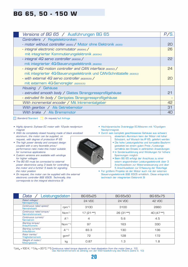
• Highly dynamic 3-phase EC motor with 10-pole neodymium magnet
• With its completely closed housing made of black anodized aluminum, the motor can be supplied, on request, with degree of protection IP 65
• The high power density and compact design coupled with a very favorable price/performance ratio make this motor suitable for numerous applications
• Custom versions are available with windings for higher voltages
• The BG 65 must be connected to external power electronics using 3 leads for controllingthe motor and a further 5 leads for signaling the rotor position
• On request, the motor can be supplied with the external electronic controller BGE 6505. Technically, this corresponds to the integral electronics SI
BG 65x25 BG 65x50 BG 65x75Data / LeistungsdatenRated voltage/Nennspannung Continuous rated speed/NenndrehzahlContinuous rated torque/NenndrehmomentContinuous current/NennstromStarting torque/Anlaufmoment Starting current/AnlaufstromRotor inertia/Trägheitsmoment Weight of motor/Motorgewicht
3100
26 (31*** )
5.6
163
130
128
1.3
2860
40 (47*** )
4.5
330
136
172
1.8
24 VDC 24 VDC 42 VDC
*)∆ϑw =100 K; **) ϑR = 20°C;***) Continuous rated torque depends on heat dissipation from the motor (see p. 10)Das Nenndrehmoment ist abhänig von der Wärmeabführung des Motors (siehe S. 10)
3100
17 (21*** )
4
97
83.3
72
0.87
rpm*)
Ncm*)
A*)
Ncm**)
A**)
gcm2
kg
21 BG
65
, 5
0 -
15
0 W
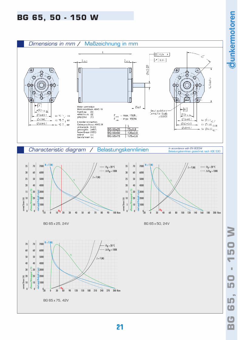
Dimensions in mm / Maßzeichnung in mm
BG 65, 50 - 150 W
Characteristic diagram / Belastungskennlinien In accordance with EN 60034Belastungskennlinien gezeichnet nach VDE 530
BG 65 x 25, 24V BG 65 x 50, 24V
BG 65 x 75, 42V
-10 0 10 20 30 40 50 60 70 80 90 100 Ncm
7000
6000
5000
4000
3000
2000
1000
0
70
60
50
40
30
20
10
0
35
30
25
20
15
10
5
0 rated
spee
d/Dr
ehza
hl n
(rpm)
effic
iency
/Wirk
ungs
grad
η (%
)
curre
nt/S
trom
I (A)
N = f (M)
J = f (M)
MN
η
-20 0 20 40 60 80 100 120 140 160 180 200 Ncm
7000
6000
5000
4000
3000
2000
1000
0
70
60
50
40
30
20
10
0
35
30
25
20
15
10
5
0 rated
spee
d/Dr
ehza
hl n
(rpm)
effic
iency
/Wirk
ungs
grad
η (%
)
curre
nt/S
trom
I (A)
N = f (M)J = f (M)
MN
η
-30 0 30 60 90 120 150 180 210 240 270 300 Ncm
7000
6000
5000
4000
3000
2000
1000
0
70
60
50
40
30
20
10
0
70
60
50
40
30
20
10
0 rated
spee
d/Dr
ehza
hl n
(rpm)
effic
iency
/Wirk
ungs
grad
η (%
)
curre
nt/S
trom
I (A)
MN
N = f (M)
J = f (M)η
ϑR = 20°C
∆ϑW = 100K
ϑR = 20°C
∆ϑW = 100K
ϑR = 20°C
∆ϑW = 100K
22
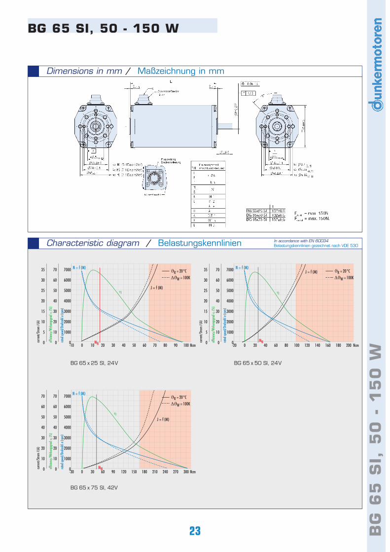
BG 65 SI, 50 - 150 W
Controllers / Regelelektroniken- integral 4Q servo controller (BG65Sl) /mit integrierter 4Q-Steuerungselektronik (BG65Sl)
Housing / Gehäuse- extruded smooth body / Glattes Strangpressprofilgehäuse- extruded fin body / Geripptes StrangpressprofilgehäuseWith incremental encoder / Mit InkrementalgeberWith gearbox / Als GetriebemotorWith brake / Als Bremsmotor
Versions of BG 65 SI / Ausführungen BG 65 SI P./S.
22
23-
423140
3100
17 (21*** )
4
97
27
72
0.95
20 ... 30
70 ... 5000
BG 65x25 SI BG 65x50 SI BG 65x75 SIData / LeistungsdatenRated voltage/Nennspannung Continuous rated speed/NenndrehzahlContinuous rated torque/NenndrehmomentContinuous current/NennstromStarting torque/Anlaufmoment Peak current/Max. zulässiger SpitzenstromRotor inertia/Trägheitsmoment Weight of motor/Motorgewicht Voltage range/Max. zulässiger SpannungsbereichRecommended speed control range/Empfohlener Drehzahlregelbereich
rpm*)
Ncm*)
A*)
Ncm**)
A**)
gcm2
kg
VDC
rpm
3100
26 (31*** )
5.6
163
27
128
1.3
20 ... 30
70 ... 5000
2860
40 (47*** )
4.5
330
27
172
1.8
20 ... 50
70 ... 5000
24 VDC 24 VDC 42 VDC
CONTROLLER
INTEGRATED
Standard/Standard On request/auf Anfrage
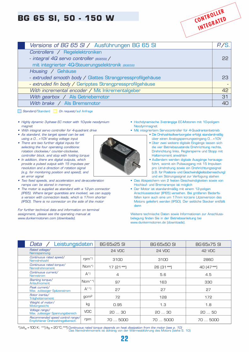
• Highly dynamic 3-phase EC motor with 10-pole neodymium magnet
• With integral servo controller for 4-quadrant drive • As standard, the target speed can be set
using a 0...+10V analog voltage input• There are two further digital inputs for
selecting the four operating conditions: rotation clockwise/ counter-clockwise, controller block, and stop with holding torque
• In addition, there are digital outputs, which provide a pulsed output with 15 impulses per revolution and a direction of rotation signal (e.g. for monitoring position and speed), and an error signal
• Two fixed speeds, and acceleration and de-acceleration ramps can be stored in memory
• The motor is supplied as standard with a 12-pin connector (IP65). Where larger quantities are involved, we can supply a version with connection leads, which is 17mm shorter (IP50). There is no connector on the side of the motor
For further technical data and information on terminalassignment, please see the operating manual at www.dunkermotoren.com (downloads).
*)∆ϑw =100 K; **) ϑR = 20°C;***) Continuous rated torque depends on heat dissipation from the motor (see p. 10)Das Nenndrehmoment ist abhänig von der Wärmeabführung des Motors (siehe S. 10)
• Hochdynamische 3-strängige EC-Motoren mit 10-poligem Neodymmagnet
• Mit integriertem Servocontroller für 4-Quadrantenbetrieb• Die Drehzahlsollwertvorgabe erfolgt standardmäßig
über einen Analogspannungseingang 0...+10V• Über zwei weitere digitale Eingänge lassen sich
die vier Betriebszustände Drehrichtung rechts, Drehrichtung links, Reglersperre und Stopp mit Haltemoment anwählen
• Außerdem werden digitale Ausgänge herausge-führt, womit ein Pulsausgang mit 15 Impulsen pro Umdrehung sowie ein Drehrichtungssignal (z.B. für Positions- und Geschwindigkeitsüberwachung)und ein Störungssignal zur Verfügung stehen
• Das Abspeichern von 2 festen Geschwindigkeiten sowie von Hochlauf- und Bremsrampe ist möglich
• Der Motor ist standardmäßig mit einem 12-poligen Anschlussstecker (IP65) versehen. Bei größeren Bedarfs- fällen kann auch eine um 17mm kürzere Litzenversion des Motors geliefert werden (IP50). Der seitliche Stecker entfälltdann
Weitere technische Daten sowie Informationen zur Anschluss-belegung finden Sie in der Betriebsanleitung bei www.dunkermotoren.de (downloads).
23 BG
65
SI,
50
- 1
50
W
Dimensions in mm / Maßzeichnung in mm
BG 65 SI, 50 - 150 W
Characteristic diagram / Belastungskennlinien In accordance with EN 60034Belastungskennlinien gezeichnet nach VDE 530
BG 65 x 25 SI, 24V BG 65 x 50 SI, 24V
BG 65 x 75 SI, 42V
-10 0 10 20 30 40 50 60 70 80 90 100 Ncm
7000
6000
5000
4000
3000
2000
1000
0
70
60
50
40
30
20
10
0
35
30
25
20
15
10
5
0 rated
spee
d/Dr
ehza
hl n
(rpm)
effic
iency
/Wirk
ungs
grad
η (%
)
curre
nt/S
trom
I (A)
N = f (M)
J = f (M)
MN
η
-20 0 20 40 60 80 100 120 140 160 180 200 Ncm
7000
6000
5000
4000
3000
2000
1000
0
70
60
50
40
30
20
10
0
35
30
25
20
15
10
5
0 rated
spee
d/Dr
ehza
hl n
(rpm)
effic
iency
/Wirk
ungs
grad
η (%
)
curre
nt/S
trom
I (A)
N = f (M)J = f (M)
MN
η
-30 0 30 60 90 120 150 180 210 240 270 300 Ncm
7000
6000
5000
4000
3000
2000
1000
0
70
60
50
40
30
20
10
0
70
60
50
40
30
20
10
0 rated
spee
d/Dr
ehza
hl n
(rpm)
effic
iency
/Wirk
ungs
grad
η (%
)
curre
nt/S
trom
I (A)
MN
N = f (M)
J = f (M)η
ϑR = 20°C
∆ϑW = 100K
ϑR = 20°C
∆ϑW = 100K
ϑR = 20°C
∆ϑW = 100K
24
• Hochdynamische 3-strängige EC-Motoren mit 10-poligem Neodymmagnet
• Mit integriertem Motioncontroller für 4-Quadrantenbetrieb mit dynamischer Positionierung
• Mit CAN-Schnittstelle, dadurch niedriger Verkabelungsaufwand
• Mit Hilfe des integrierten Motioncontrollers und eines integrierten Rotorlagegebers können auch sehr komplexe Fahrprofile abgearbeitet werden
• Die wesentlichen Parameter einer Bahnkurve wie Positions-, Geschwindigkeits- und Beschleunigungswerte können über die Can-Schnittstelle auch "in fly" verändert werden
• Mit dem optional angebauten Inkrementalencoder RE 30-3-500 können Drehzahlen ab 1 rpm geregelt werden
• Für die CAN-Bus Schnittstelle wird ein CIA-empfolener 5-poliger Rundstecker verwendet. Ein weiterer 12-poliger Rundstecker dient zum Anschluss der Spannungsversorgungund weiterer I/O-Signale.
• Zur einfachen Inbetriebnahme steht ein Starterkit mit Schnittstelle für den PC und Software-CD zur Verfügung (siehe Zubehör)
Weitere technische Daten sowie Informationen zur Anschluss-belegung finden Sie in der Betriebsanleitung bei www.dunker-motoren.de (downloads). Bitte beachten Sie, dass dieserMotor nur bei Bedarfsfällen größer 100 Stück lieferbar ist.
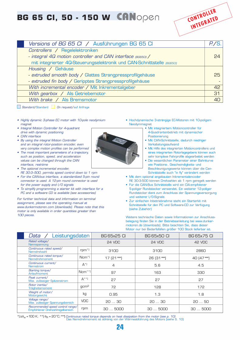
BG 65 CI, 50 - 150 W
Standard/Standard On request/auf Anfrage
Controllers / Regelelektroniken- integral 4Q motion controller and CAN interface (BG65CI) /mit integrierter 4Q-Steuerungselektronik und CAN-Schnittstelle (BG65CI)
Housing / Gehäuse- extruded smooth body / Glattes Strangpressprofilgehäuse- extruded fin body / Geripptes StrangpressprofilgehäuseWith incremental encoder / Mit InkrementalgeberWith gearbox / Als GetriebemotorWith brake / Als Bremsmotor
Versions of BG 65 CI / Ausführungen BG 65 CI P./S.
24
25-
423140
• Highly dynamic 3-phase EC motor with 10-pole neodymium magnet
• Integral Motion Controller for 4-quadrant drive with dynamic positioning
• CAN interface • By using the integral Motion Controller
and an integral rotor-position encoder, even very complex motion profiles can be performed
• The most important parameters of a trajectory,such as position, speed, and acceleration values can be changed through the CAN interface, real-time
• The optional incremental encoder, RE 30-3--500, permits speed control down to 1 rpm
• For the CAN-bus interface, a standardized 5-pin round connector is used. A 12-pin round connector is used for the power supply and I/O signals
• To simplify programming a starter kit with interface for a PC and a software CD is available (see accessories)
For further technical data and information on terminalassignment, please see the operating manual atwww.dunkermotoren.com (downloads). Please note that thismotor is only available in order quantities greater than100 pieces.
3100
17 (21*** )
4
97
27
72
0.95
20 ... 30
30 ... 5000
BG 65x25 CI BG 65x50 CI BG 65x75 CIData / LeistungsdatenRated voltage/Nennspannung Continuous rated speed/NenndrehzahlContinuous rated torque/NenndrehmomentContinuous current/NennstromStarting torque/Anlaufmoment Peak current/Max. zulässiger SpitzenstromRotor inertia/Trägheitsmoment Weight of motor/Motorgewicht Voltage range/Max. zulässiger SpannungsbereichRecommended speed control range/Empfohlener Drehzahlregelbereich
rpm*)
Ncm*)
A*)
Ncm**)
A**)
gcm2
kg
VDC
rpm
3100
26 (31*** )
5.6
163
27
128
1.3
20 ... 30
30 ... 5000
2860
40 (47*** )
4.5
330
27
172
1.8
20 ... 50
30 ... 5000
24 VDC 24 VDC 42 VDC
CONTROLLER
INTEGRATED
*)∆ϑw =100 K; **) ϑR = 20°C;***) Continuous rated torque depends on heat dissipation from the motor (see p. 10)Das Nenndrehmoment ist abhänig von der Wärmeabführung des Motors (siehe S. 10)
25 BG
65
CI,
50
- 1
50
W
Dimensions in mm / Maßzeichnung in mm
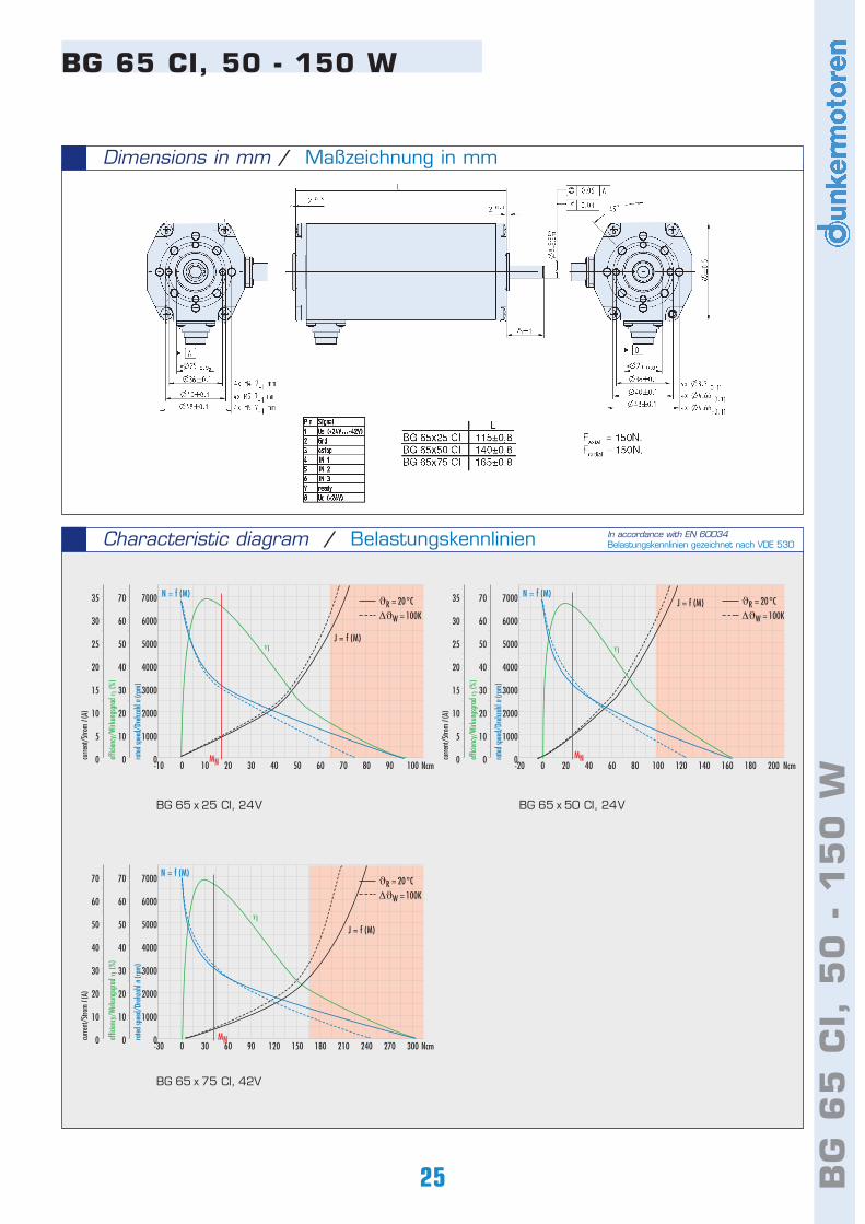
BG 65 CI, 50 - 150 W
Characteristic diagram / Belastungskennlinien In accordance with EN 60034Belastungskennlinien gezeichnet nach VDE 530
BG 65 x 25 CI, 24V BG 65 x 50 CI, 24V
BG 65 x 75 CI, 42V
-10 0 10 20 30 40 50 60 70 80 90 100 Ncm
7000
6000
5000
4000
3000
2000
1000
0
70
60
50
40
30
20
10
0
35
30
25
20
15
10
5
0 rated
spee
d/Dr
ehza
hl n
(rpm)
effic
iency
/Wirk
ungs
grad
η (%
)
curre
nt/S
trom
I (A)
N = f (M)
J = f (M)
MN
η
-20 0 20 40 60 80 100 120 140 160 180 200 Ncm
7000
6000
5000
4000
3000
2000
1000
0
70
60
50
40
30
20
10
0
35
30
25
20
15
10
5
0 rated
spee
d/Dr
ehza
hl n
(rpm)
effic
iency
/Wirk
ungs
grad
η (%
)
curre
nt/S
trom
I (A)
N = f (M)J = f (M)
MN
η
-30 0 30 60 90 120 150 180 210 240 270 300 Ncm
7000
6000
5000
4000
3000
2000
1000
0
70
60
50
40
30
20
10
0
70
60
50
40
30
20
10
0 rated
spee
d/Dr
ehza
hl n
(rpm)
effic
iency
/Wirk
ungs
grad
η (%
)
curre
nt/S
trom
I (A)
MN
N = f (M)
J = f (M)η
ϑR = 20°C
∆ϑW = 100K
ϑR = 20°C
∆ϑW = 100K
ϑR = 20°C
∆ϑW = 100K
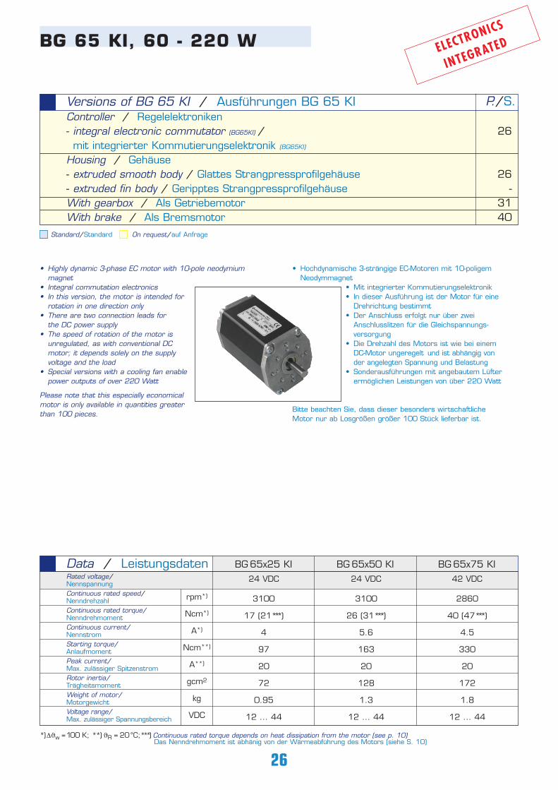
• Highly dynamic 3-phase EC motor with 10-pole neodymium magnet
• Integral commutation electronics• In this version, the motor is intended for
rotation in one direction only • There are two connection leads for
the DC power supply • The speed of rotation of the motor is
unregulated, as with conventional DC motor; it depends solely on the supply voltage and the load
• Special versions with a cooling fan enable power outputs of over 220 Watt
Please note that this especially economicalmotor is only available in quantities greaterthan 100 pieces.
• Hochdynamische 3-strängige EC-Motoren mit 10-poligem Neodymmagnet
• Mit integrierter Kommutierungselektronik• In dieser Ausführung ist der Motor für eine
Drehrichtung bestimmt• Der Anschluss erfolgt nur über zwei
Anschlusslitzen für die Gleichspannungs- versorgung
• Die Drehzahl des Motors ist wie bei einem DC-Motor ungeregelt und ist abhängig von der angelegten Spannung und Belastung
• Sonderausführungen mit angebautem Lüfter ermöglichen Leistungen von über 220 Watt
Bitte beachten Sie, dass dieser besonders wirtschaftlicheMotor nur ab Losgrößen größer 100 Stück lieferbar ist.
26
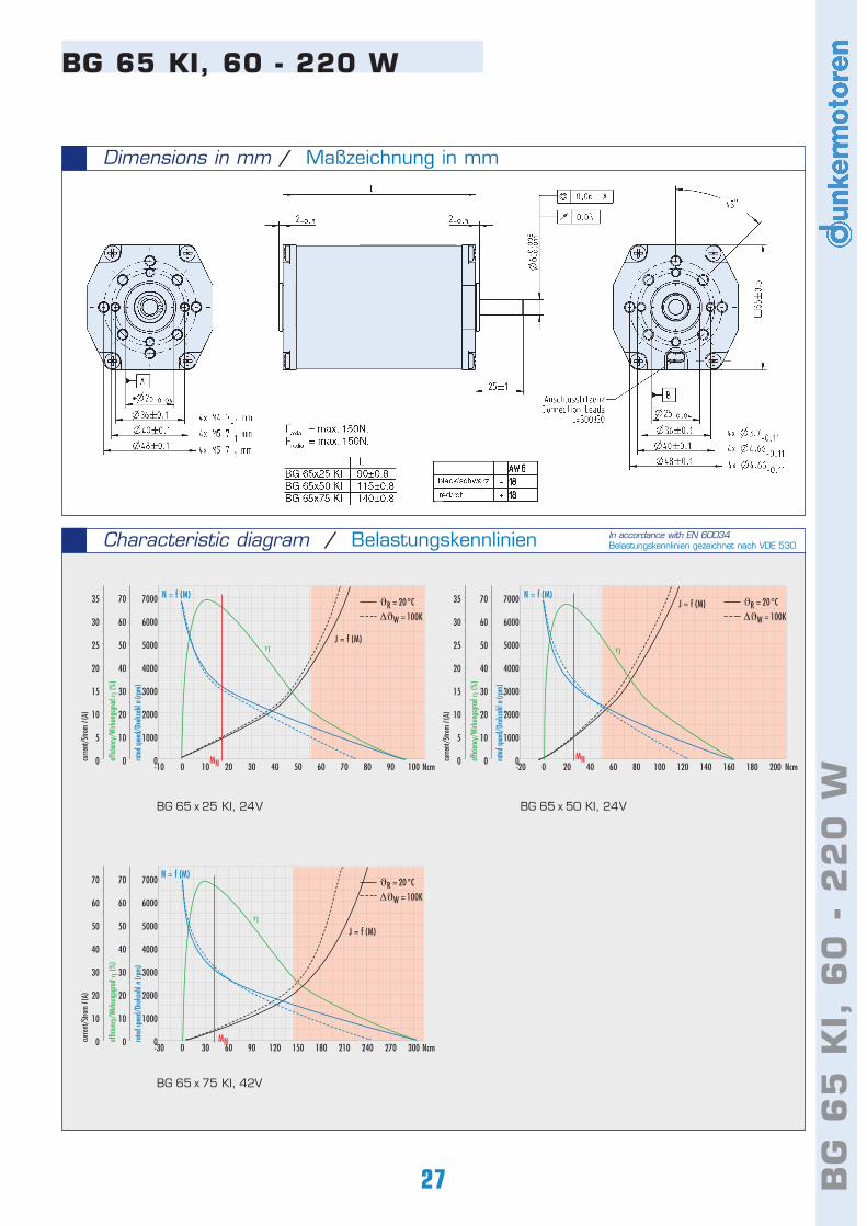
BG 65 KI, 60 - 220 W
Standard/Standard On request/auf Anfrage
Controller / Regelelektroniken- integral electronic commutator (BG65KI) /mit integrierter Kommutierungselektronik (BG65KI)
Housing / Gehäuse- extruded smooth body / Glattes Strangpressprofilgehäuse- extruded fin body / Geripptes StrangpressprofilgehäuseWith gearbox / Als GetriebemotorWith brake / Als Bremsmotor
Versions of BG 65 KI / Ausführungen BG 65 KI P./S.
26
26-
3140
3100
17 (21*** )
4
97
20
72
0.95
12 ... 44
BG 65x25 KI BG 65x50 KI BG 65x75 KIData / LeistungsdatenRated voltage/Nennspannung Continuous rated speed/NenndrehzahlContinuous rated torque/NenndrehmomentContinuous current/NennstromStarting torque/Anlaufmoment Peak current/Max. zulässiger SpitzenstromRotor inertia/Trägheitsmoment Weight of motor/Motorgewicht Voltage range/Max. zulässiger Spannungsbereich
rpm*)
Ncm*)
A*)
Ncm**)
A**)
gcm2
kg
VDC
3100
26 (31*** )
5.6
163
20
128
1.3
12 ... 44
2860
40 (47*** )
4.5
330
20
172
1.8
12 ... 44
24 VDC 24 VDC 42 VDC
ELECTRONICS
INTEGRATED
*)∆ϑw =100 K; **) ϑR = 20°C;***) Continuous rated torque depends on heat dissipation from the motor (see p. 10)Das Nenndrehmoment ist abhänig von der Wärmeabführung des Motors (siehe S. 10)
27 BG
65
KI,
60
- 2
20
W
Dimensions in mm / Maßzeichnung in mm
BG 65 KI, 60 - 220 W
Characteristic diagram / Belastungskennlinien In accordance with EN 60034Belastungskennlinien gezeichnet nach VDE 530
BG 65 x 25 KI, 24V BG 65 x 50 KI, 24V
BG 65 x 75 KI, 42V
-10 0 10 20 30 40 50 60 70 80 90 100 Ncm
7000
6000
5000
4000
3000
2000
1000
0
70
60
50
40
30
20
10
0
35
30
25
20
15
10
5
0 rated
spee
d/Dr
ehza
hl n
(rpm)
effic
iency
/Wirk
ungs
grad
η (%
)
curre
nt/S
trom
I (A)
N = f (M)
J = f (M)
MN
η
-20 0 20 40 60 80 100 120 140 160 180 200 Ncm
7000
6000
5000
4000
3000
2000
1000
0
70
60
50
40
30
20
10
0
35
30
25
20
15
10
5
0 rated
spee
d/Dr
ehza
hl n
(rpm)
effic
iency
/Wirk
ungs
grad
η (%
)
curre
nt/S
trom
I (A)
N = f (M)J = f (M)
MN
η
-30 0 30 60 90 120 150 180 210 240 270 300 Ncm
7000
6000
5000
4000
3000
2000
1000
0
70
60
50
40
30
20
10
0
70
60
50
40
30
20
10
0 rated
spee
d/Dr
ehza
hl n
(rpm)
effic
iency
/Wirk
ungs
grad
η (%
)
curre
nt/S
trom
I (A)
MN
N = f (M)
J = f (M)η
ϑR = 20°C
∆ϑW = 100K
ϑR = 20°C
∆ϑW = 100K
ϑR = 20°C
∆ϑW = 100K
28
• Hochdynamischer 4-strängiger EC-Motor• Mit 4-poligem Neodymmagnet beim BG 83S bzw.
Ferritmagnet beim BG 83 • Die Magnete des 4poligen Rotors sind zur Verringerung der
Rastkräfte gegeneinander azimutal versetzt• Für den Betrieb dieser Motoren ist eine
zusätzliche Leistungselektronik notwendigWir empfehlen die Ansteuerung mit der 4Q-Leistungselektronik BGE 9010
• Ausführungen mit Klemmkasten und Schutzhaube (IP 54) sind möglich
• Diese Motoren werden auf Anfrage auch mitanderen Wicklungen hergestellt
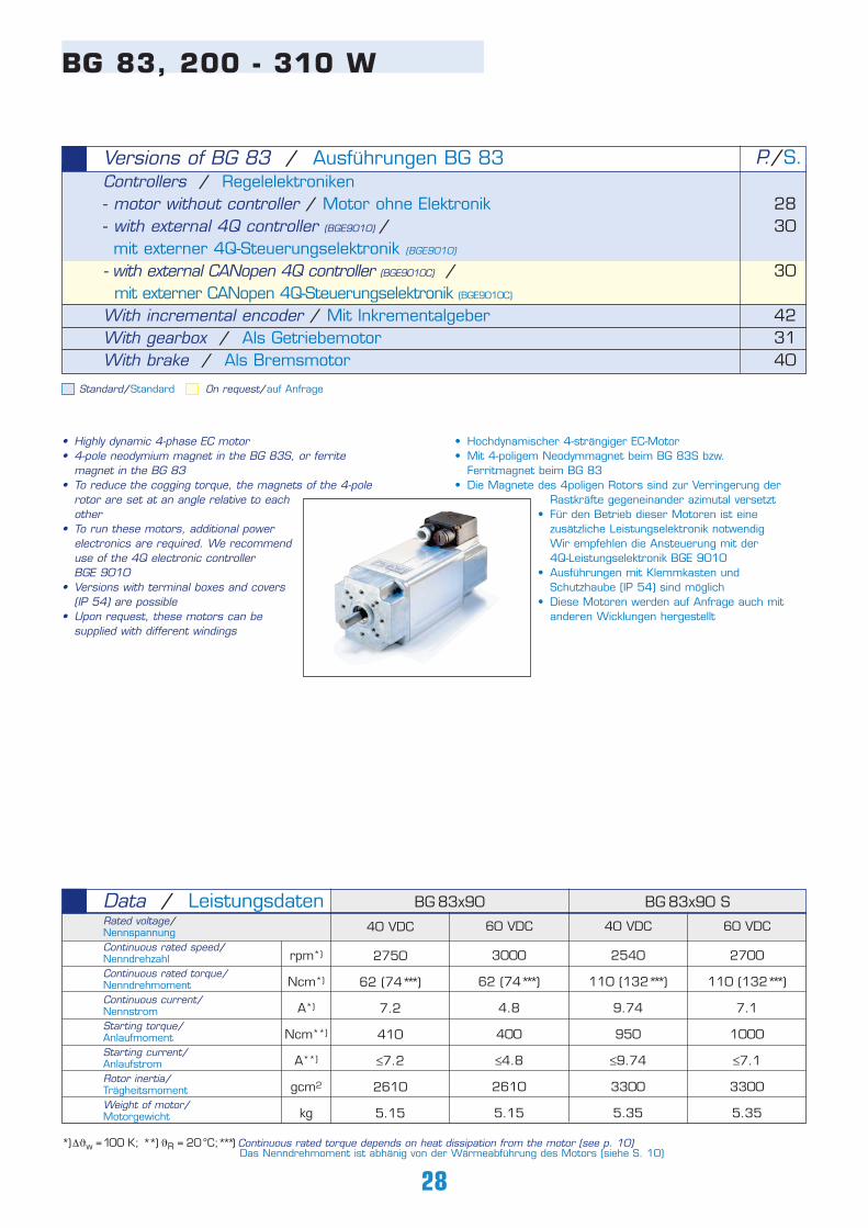
BG 83, 200 - 310 W
Standard/Standard On request/auf Anfrage
Controllers / Regelelektroniken- motor without controller / Motor ohne Elektronik- with external 4Q controller (BGE9010) /mit externer 4Q-Steuerungselektronik (BGE9010)
- with external CANopen 4Q controller (BGE9010C) / mit externer CANopen 4Q-Steuerungselektronik (BGE9010C)
With incremental encoder / Mit InkrementalgeberWith gearbox / Als GetriebemotorWith brake / Als Bremsmotor
Versions of BG 83 / Ausführungen BG 83 P./S.
2830
30
423140
• Highly dynamic 4-phase EC motor• 4-pole neodymium magnet in the BG 83S, or ferrite
magnet in the BG 83 • To reduce the cogging torque, the magnets of the 4-pole
rotor are set at an angle relative to each other
• To run these motors, additional power electronics are required. We recommend use of the 4Q electronic controller BGE 9010
• Versions with terminal boxes and covers (IP 54) are possible
• Upon request, these motors can be supplied with different windings
40 VDC
2750
62 (74*** )
7.2
410
≤7.2
2610
5.15
BG 83x90 BG 83x90 SData / LeistungsdatenRated voltage/Nennspannung Continuous rated speed/NenndrehzahlContinuous rated torque/NenndrehmomentContinuous current/NennstromStarting torque/Anlaufmoment Starting current/AnlaufstromRotor inertia/Trägheitsmoment Weight of motor/Motorgewicht
rpm*)
Ncm*)
A*)
Ncm**)
A**)
gcm2
kg
60 VDC
3000
62 (74*** )
4.8
400
≤4.8
2610
5.15
40 VDC
2540
110 (132*** )
9.74
950
≤9.74
3300
5.35
60 VDC
2700
110 (132*** )
7.1
1000
≤7.1
3300
5.35
*)∆ϑw =100 K; **) ϑR = 20°C;***) Continuous rated torque depends on heat dissipation from the motor (see p. 10)Das Nenndrehmoment ist abhänig von der Wärmeabführung des Motors (siehe S. 10)
29 BG
83
, 2
00
- 3
10
W
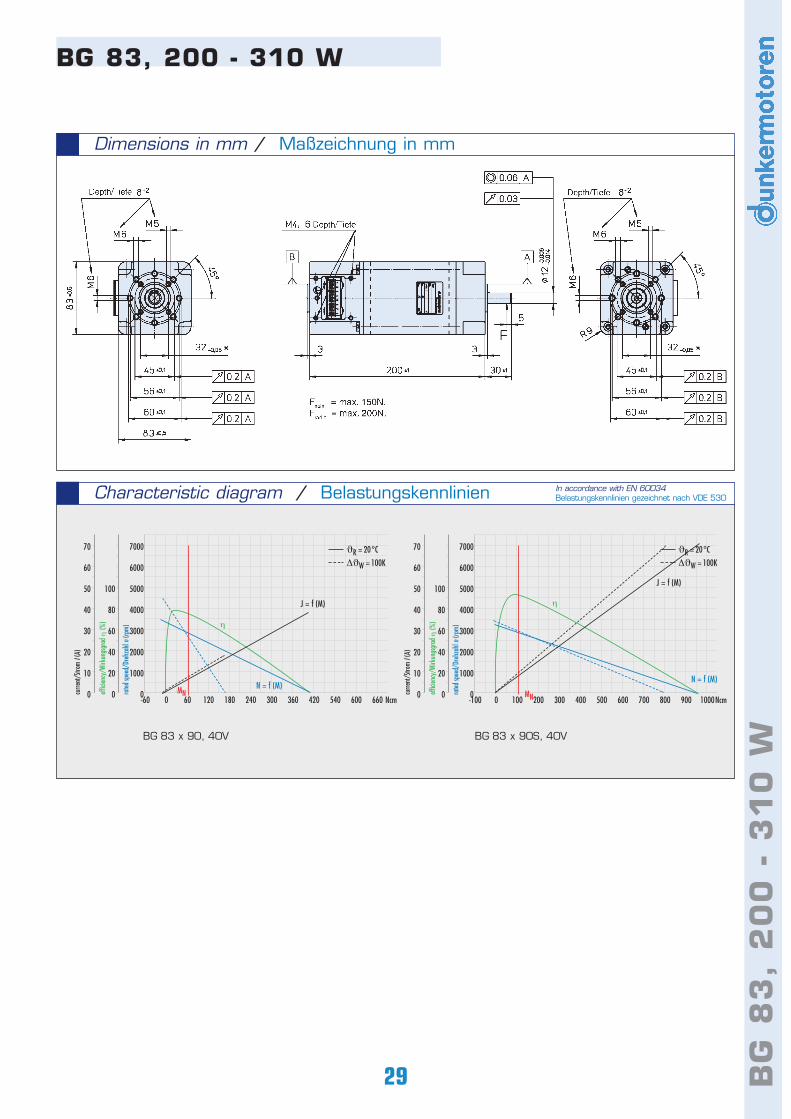
Dimensions in mm / Maßzeichnung in mm
BG 83, 200 - 310 W
BG 83 x 90, 40V
Characteristic diagram / Belastungskennlinien
BG 83 x 90S, 40V
In accordance with EN 60034Belastungskennlinien gezeichnet nach VDE 530
-60 0 60 120 180 240 300 360 420 540 600 660 Ncm
7000
6000
5000
4000
3000
2000
1000
0
100
80
60
40
20
0
70
60
50
40
30
20
10
0 rated
spee
d/Dr
ehza
hl n
(rpm)
effic
iency
/Wirk
ungs
grad
η (%
)
curre
nt/S
trom
I (A)
N = f (M)
J = f (M)
MN
η
-100 0 100 200 300 400 500 600 700 800 900 1000Ncm
7000
6000
5000
4000
3000
2000
1000
0
100
80
60
40
20
0
70
60
50
40
30
20
10
0 rated
spee
d/Dr
ehza
hl n
(rpm)
effic
iency
/Wirk
ungs
grad
η (%
)
curre
nt/S
trom
I (A)
N = f (M)
J = f (M)
MN
η
ϑR = 20°C
∆ϑW = 100K
ϑR = 20°C
∆ϑW = 100K
• Der digitale Servoregler BGE 9010 verfügt über vielfältige Funktionen
• Die lagegeregelte Stillstandsüberwachung mit Haltemoment und programmierbare Rampen machen den Regler BGE
9010 universell einsetzbar• 4-Quadranten Drehzahlregelbetrieb, Para-
meter bequem über RS 232 einstellbar• Optional mit CAN-Schnittstelle erhältlich• Je 8 digitale Ein- und Ausgänge• Drehzahlsollwert wahlweise digital einstellbar
oder über analoge Sollwertspannung• Ruckfreier Drehmomentverlauf auch bei klei-
nen Drehzahlen• Umfassende Schutzeinrichtungen• Einfachste Inbetriebnahme durch werkseitige
Voreinstellungen• In Kombination mit der Regelelektronik BGE
9010 ist standardmäßig die Anbringung eines Inkremental-encoders RE 30-3 TI notwendig
Bitte beachten Sie, dass bei der BGE 9010 ein Steckersatzmitbestellt werden muss. Weitere technische Daten sowieInformationen zur Anschlussbelegung finden Sie in derBetriebsanleitung bei www.dunkermotoren.de (downloads).
30
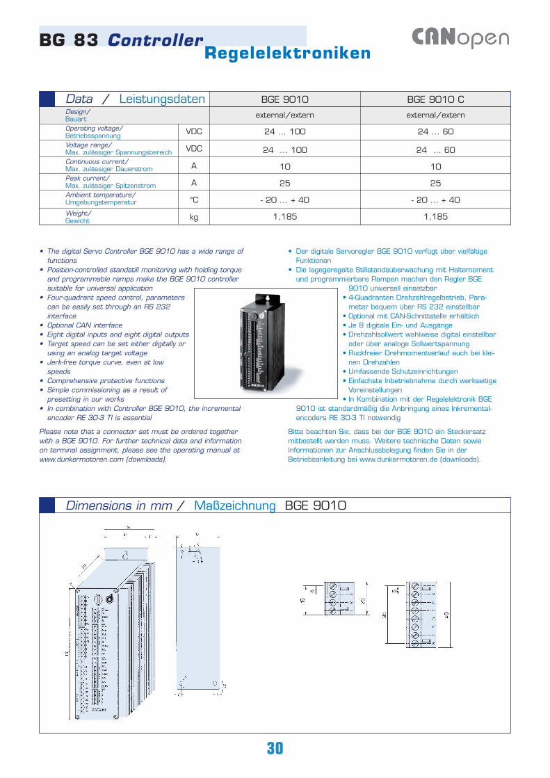
Dimensions in mm / Maßzeichnung BGE 9010
external/extern
24 ... 100
24 ... 100
10
25
- 20 ... + 40
1,185
BGE 9010
external/extern
24 ... 60
24 ... 60
10
25
- 20 ... + 40
1,185
BGE 9010 CData / LeistungsdatenDesign/BauartOperating voltage/Betriebsspannung Voltage range/Max. zulässiger SpannungsbereichContinuous current/Max. zulässiger Dauerstrom Peak current/Max. zulässiger SpitzenstromAmbient temperature/Umgebungstemperatur
Weight/Gewicht
VDC
VDC
A
A
°C
kg
• The digital Servo Controller BGE 9010 has a wide range of functions
• Position-controlled standstill monitoring with holding torque and programmable ramps make the BGE 9010 controller suitable for universal application
• Four-quadrant speed control, parameters can be easily set through an RS 232 interface
• Optional CAN interface• Eight digital inputs and eight digital outputs• Target speed can be set either digitally or
using an analog target voltage• Jerk-free torque curve, even at low
speeds • Comprehensive protective functions• Simple commissioning as a result of
presetting in our works• In combination with Controller BGE 9010, the incremental
encoder RE 30-3 TI is essential
Please note that a connector set must be ordered togetherwith a BGE 9010. For further technical data and informationon terminal assignment, please see the operating manual atwww.dunkermotoren.com (downloads).
BG 83 ControllerRegelelektroniken

31 PLG
/S
G G
ears
PLG
/S
G G
etri
ebe
Worm gearboxes (SG) are noted for their very quiet
running. The worm-gear shaft has bearings on both
sides. The gear components, made of bronze or steel,
and the lubrication ensure a long service life at the rated
torque. In many applications, the location of the output
shaft at 90° to the motor shaft provides an optimum
design solution. On request, worm-gearboxes can be
supplied with a hollow output shaft.
Planetary gearboxes (PLG) have the highest continuous
torque capacity of all types of gearbox; at the same time
they have a very compact form, low weight, and excellent
efficiency. Self-centering planet gears ensure a symmetri-
cal force distribution. The ring gear also forms the hou-
sing of the gearbox.
The gearbox output shaft is supported in two ball bea-
rings so that it can withstand high axial and radial loads.
The gearboxes are customized, e.g. for use in especially
low ambient temperatures, or as high-power gearboxes
with reinforced output shafts, or with special lubricants
for very long service life.
For information on the selection of suitable motors and
gearboxes, please see pages 10-11 in this catalog. This
will enable you to make an initial selection on the basis of
speed and load ranges. On request, we will adapt a drive
precisely to your operating conditions.
Schneckengetriebe (SG) zeichnen sich durch hohe
Laufruhe aus. Die Schneckenradwelle ist beidseitig gela-
gert. Die Verzahnungsteile aus Bronze bzw. Stahl sowie
eine Fettschmierung gewährleisten eine hohe Lebens-
dauer bei den angegebenen Nenndrehmomenten. Bei
vielen Anwendungen ist die um 90° gegenüber der
Motorwelle versetzte Getriebewelle von baulichen
Gegebenheiten her optimal. Auf Anfrage sind Schnecken-
getriebe auch mit Hohlwelle lieferbar.
Planetengetriebe (PLG) haben die höchsten zulässigen
Dauerdrehmomente aller Getriebe bei gleichzeitig sehr
kompakter Bauform, geringem Gewicht und ausgezeich-
netem Wirkungsgrad. Selbstzentrierende Planetenräder
garantieren eine symmetrische Kraftverteilung. Das
Hohlrad ist gleichzeitig auch Getriebegehäuse. Zweifach
kugelgelagerte Getriebeausgangswellen nehmen hohe
axiale und radiale Belastungen auf.
Die Getriebe sind in zahlreichen Sonderausführungen
lieferbar, z. B. für den Einsatz bei besonders niedrigen
Umgebungstemperaturen oder als Hochleistungsgetrie-
be mit verstärkter Ausgangswelle und spezieller Schmie-
rung für höchste Lebensdauer. Informationen zur Aus-
wahl des passenden Motors und Getriebes finden auf
den Seiten 10-11 in diesem Katalog. Der Katalog gestat-
tet eine Vorauswahl in Drehzahl und Lastbereichen. Eine
exakte Anpassung des Antriebs an Ihre Betriebs-
bedingungen erfolgt auf Anfrage.
PLG/SG Getriebe für BG-MotorenPLG/SG Gears for BLDC Motors
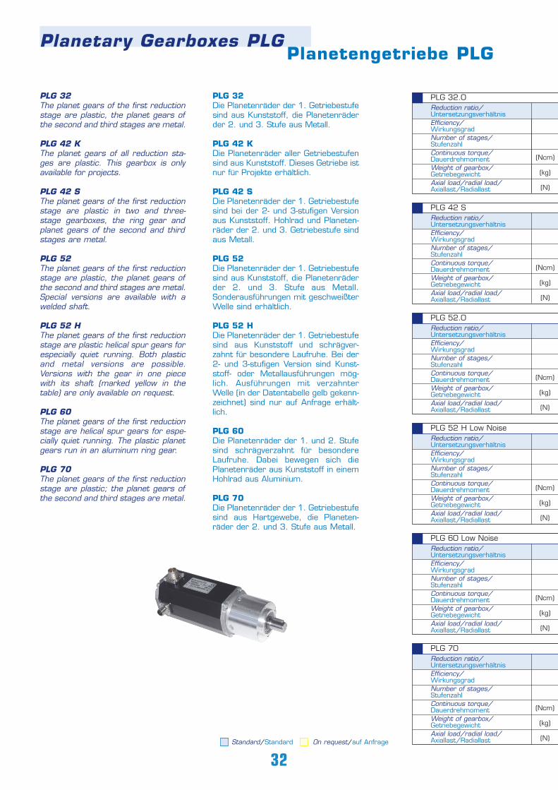
Planetary Gearboxes PLGPlanetengetriebe PLG
PLG 32 The planet gears of the first reductionstage are plastic, the planet gears ofthe second and third stages are metal.
PLG 42 K The planet gears of all reduction sta-ges are plastic. This gearbox is onlyavailable for projects.
PLG 42 S The planet gears of the first reductionstage are plastic in two and three-stage gearboxes, the ring gear andplanet gears of the second and thirdstages are metal.
PLG 52 The planet gears of the first reductionstage are plastic, the planet gears ofthe second and third stages are metal.Special versions are available with awelded shaft.
PLG 52 H The planet gears of the first reductionstage are plastic helical spur gears forespecially quiet running. Both plasticand metal versions are possible.Versions with the gear in one piecewith its shaft (marked yellow in thetable) are only available on request.
PLG 60 The planet gears of the first reductionstage are helical spur gears for espe-cially quiet running. The plastic planetgears run in an aluminum ring gear.
PLG 70 The planet gears of the first reductionstage are plastic; the planet gears ofthe second and third stages are metal.
PLG 32Die Planetenräder der 1. Getriebestufesind aus Kunststoff, die Planetenräderder 2. und 3. Stufe aus Metall.
PLG 42 K Die Planetenräder aller Getriebestufensind aus Kunststoff. Dieses Getriebe istnur für Projekte erhältlich.
PLG 42 S Die Planetenräder der 1. Getriebestufesind bei der 2- und 3-stufigen Versionaus Kunststoff. Hohlrad und Planeten-räder der 2. und 3. Getriebestufe sindaus Metall.
PLG 52Die Planetenräder der 1. Getriebestufesind aus Kunststoff, die Planetenräderder 2. und 3. Stufe aus Metall.Sonderausführungen mit geschweißterWelle sind erhältlich.
PLG 52 H Die Planetenräder der 1. Getriebestufesind aus Kunststoff und schrägver-zahnt für besondere Laufruhe. Bei der2- und 3-stufigen Version sind Kunst-stoff- oder Metallausführungen mög-lich. Ausführungen mit verzahnterWelle (in der Datentabelle gelb gekenn-zeichnet) sind nur auf Anfrage erhält-lich.
PLG 60 Die Planetenräder der 1. und 2. Stufesind schrägverzahnt für besondereLaufruhe. Dabei bewegen sich diePlanetenräder aus Kunststoff in einemHohlrad aus Aluminium.
PLG 70 Die Planetenräder der 1. Getriebestufesind aus Hartgewebe, die Planeten-räder der 2. und 3. Stufe aus Metall.
Reduction ratio/ UntersetzungsverhältnisEfficiency/WirkungsgradNumber of stages/StufenzahlContinuous torque/DauerdrehmomentWeight of gearbox/GetriebegewichtAxial load/radial load/Axiallast/RadiallastStandard/Standard On request/auf Anfrage
32
PLG 70
Reduction ratio/ UntersetzungsverhältnisEfficiency/WirkungsgradNumber of stages/StufenzahlContinuous torque/DauerdrehmomentWeight of gearbox/GetriebegewichtAxial load/radial load/Axiallast/Radiallast
PLG 60 Low Noise
Reduction ratio/ UntersetzungsverhältnisEfficiency/WirkungsgradNumber of stages/StufenzahlContinuous torque/DauerdrehmomentWeight of gearbox/GetriebegewichtAxial load/radial load/Axiallast/Radiallast
PLG 52 H Low Noise
Reduction ratio/ UntersetzungsverhältnisEfficiency/WirkungsgradNumber of stages/StufenzahlContinuous torque/DauerdrehmomentWeight of gearbox/GetriebegewichtAxial load/radial load/Axiallast/Radiallast
PLG 52.0
Reduction ratio/ UntersetzungsverhältnisEfficiency/WirkungsgradNumber of stages/StufenzahlContinuous torque/DauerdrehmomentWeight of gearbox/GetriebegewichtAxial load/radial load/Axiallast/Radiallast
PLG 42 S
Reduction ratio/ UntersetzungsverhältnisEfficiency/WirkungsgradNumber of stages/StufenzahlContinuous torque/DauerdrehmomentWeight of gearbox/GetriebegewichtAxial load/radial load/Axiallast/Radiallast
(Ncm)
(kg)
(N)
PLG 32.0
(Ncm)
(kg)
(N)
(Ncm)
(kg)
(N)
(Ncm)
(kg)
(N)
(Ncm)
(kg)
(N)
(Ncm)
(kg)
(N)
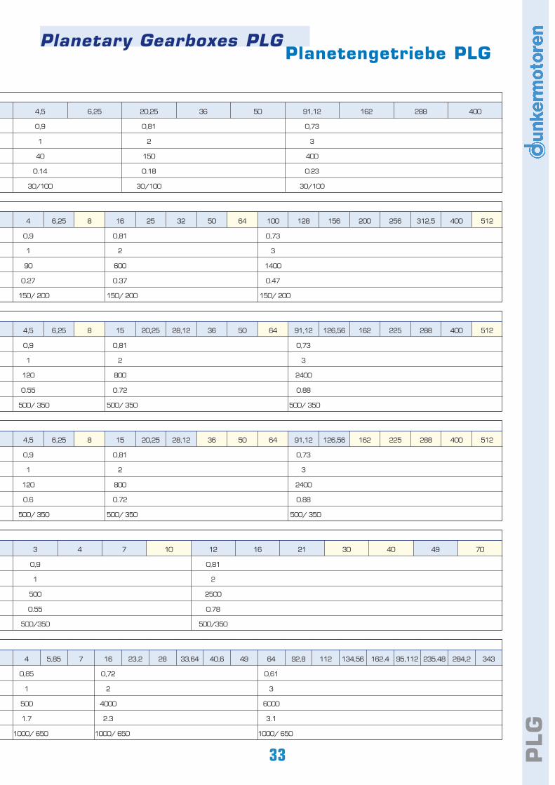
PLG
Planetary Gearboxes PLGPlanetengetriebe PLG
33
4 5,85 7 16 23,2 28 33,64 40,6 49 64 92,8 112 134,56 162,4 95,112 235,48 284,2 343
0,85 0,72 0,61
1 2 3
500 4000 6000
1.7 2.3 3.1
1000/ 650 1000/ 650 1000/ 650
3 4 7 10 12 16 21 30 40 49 70
0,9 0,81
1 2
500 2500
0.55 0.78
500/350 500/350
4,5 6,25 8 15 20,25 28,12 36 50 64 91,12 126,56 162 225 288 400 512
0,9 0,81 0,73
1 2 3
120 800 2400
0.6 0.72 0.88
500/ 350 500/ 350 500/ 350
4 6,25 8 16 25 32 50 64 100 128 156 200 256 312,5 400 512
0,9 0,81 0,73
1 2 3
90 600 1400
0.27 0.37 0.47
150/ 200 150/ 200 150/ 200
4,5 6,25 20,25 36 50 91,12 162 288 400
0,9 0,81 0,73
1 2 3
40 150 400
0.14 0.18 0.23
30/100 30/100 30/100
4,5 6,25 8 15 20,25 28,12 36 50 64 91,12 126,56 162 225 288 400 512
0,9 0,81 0,73
1 2 3
120 800 2400
0.55 0.72 0.88
500/ 350 500/ 350 500/ 350
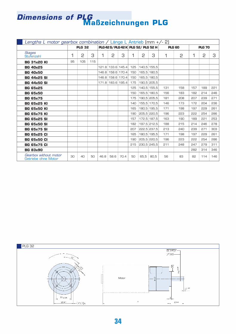
1 2 3
157 189 221
182 214 246
207 239 271
172 204 236
197 229 261
222 254 286
189 221 253
214 246 278
239 271 303
197 229 261
222 254 286
247 279 311
282 314 346
82 114 146
34
PLG 32
Motor
Lengths L motor gearbox combination / Länge L Antrieb (mm +/- 2)
1 2 3
121.8 133.6 145.4
146.8 158.6 170.4
146.8 158.6 170.4
171.8 183.6 195.4
46.8 58.6 70.4
1 2 3
125 140,5 155,5
150 165,5 180,5
150 165,5 180,5
175 190,5 205,5
125 140,5 155,5
150 165,5 180,5
175 190,5 205,5
140 155,5 170,5
165 180,5 195,5
190 205,5 220,5
157 172,5 187,5
182 197,5 212,5
207 222,5 237,5
165 180,5 195,5
190 205,5 220,5
215 230,5 245,5
50 65,5 80,5
1 2
131 158
156 183
181 208
146 173
171 198
196 223
163 190
188 215
213 240
171 198
196 223
211 248
56 83
PLG42S/PLG42K PLG 52/ PLG 52 H PLG 60 PLG 70
Dimensions of PLGMaßzeichnungen PLG
StagesStufenzahl
BG 31x20 KIBG 40x25BG 40x50BG 44x25 SIBG 44x50 SIBG 65x25BG 65x50BG 65x75BG 65x25 KIBG 65x50 KIBG 65x75 KIBG 65x25 SIBG 65x50 SIBG 65x75 SIBG 65x25 CIBG 65x50 CIBG 65x75 CIBG 83x90Gearbox without motorGetriebe ohne Motor
1 2 395 105 115
30 40 50
PLG 32
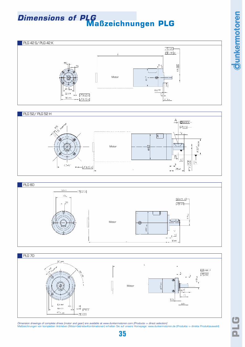
35 PLG
PLG 42 S/PLG 42 K
PLG 52/ PLG 52 H
PLG 60
PLG 70
Dimension drawings of complete drives (motor and gear) are available at www.dunkermotoren.com (Products -> direct selection)Maßzeichnungen von kompletten Antrieben (Motor-Getriebe-Kombinationen) erhalten Sie auf unsere Homepage: www.dunkermotoren.de (Produkte -> direkte Produktauswahl)
Dimensions of PLGMaßzeichnungen PLG
Motor
Motor
Motor
Motor
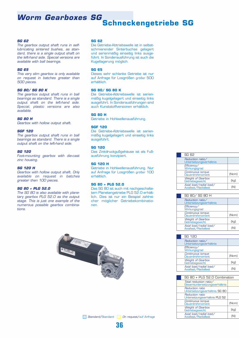
SG 62Die Getriebe-Abtriebswelle ist in selbst-schmierender Sinterbuchse gelagertund serienmäßig einseitig links ausge-führt. In Sonderausführung ist auch dieKugellagerung möglich.
SG 65Dieses sehr schlanke Getriebe ist nurauf Anfrage für Losgrößen größer 500erhältlich.
SG 80/ SG 80 KDie Getriebe-Abtriebswelle ist serien-mäßig kugelgelagert und einseitig linksausgeführt. In Sonderausführungen sindauch Kunststoffversionen erhältlich.
SG 80 H Getriebe in Hohlwellenausführung.
SGF 120Die Getriebe-Abtriebswelle ist serien-mäßig kugelgelagert und einseitig linksausgeführt.
SG 120Das Zinkdruckgußgehäuse ist als Fuß-ausführung konzipiert.
SG 120 HGetriebe in Hohlwellenausführung. Nurauf Anfrage für Losgrößen größer 100erhältlich.
SG 80 + PLG 52.0Das SG 80 ist auch mit nachgeschalte-tem Planetengetriebe PLG 52.0 erhält-lich. Dies ist nur ein Beispiel zahlrei-cher möglicher Getriebekombinatio-nen.
Worm Gearboxes SGSchneckengetriebe SG
SG 62The gearbox output shaft runs in self-lubricating sintered bushes, as stan-dard, there is a single output shaft onthe left-hand side. Special versions areavailable with ball bearings.
SG 65This very slim gearbox is only availableon request in batches greater than500 pieces.
SG 80/ SG 80 KThe gearbox output shaft runs in ballbearings as standard. There is a singleoutput shaft on the left-hand side.Special, plastic versions are alsoavailable.
SG 80 H Gearbox with hollow output shaft.
SGF 120The gearbox output shaft runs in ballbearings as standard. There is a singleoutput shaft on the left-hand side.
SG 120Foot-mounting gearbox with die-castzinc housing.
SG 120 HGearbox with hollow output shaft. Onlyavailable on request in batchesgreater then 100 pieces.
SG 80 + PLG 52.0The SG 80 is also available with plane-tary gearbox PLG 52.0 as the outputstage. This is just one example of thenumerous possible gearbox combina-tions.
Standard/Standard On request/auf Anfrage
36
Total reduction ratio/ GesamtuntersetzungsverhältnisReduction ratio Untersetzungsverhältnis SG 80Reduction ratio Untersetzungsverhältnis PLG 52Continuous torqueDauerdrehmoment Weight of GearboxGetriebegewichtAxial load/radial load/Axiallast/Radiallast
SG 80 + PLG 52.0 Combination
Reduction ratio/ UntersetzungsverhältnisEfficiency/WirkungsgradContinuous torqueDauerdrehmomentWeight of GearboxGetriebegewichtAxial load/radial load/Axiallast/Radiallast
SG 120
Reduction ratio/ UntersetzungsverhältnisEfficiency/WirkungsgradContinuous torqueDauerdrehmomentWeight of GearboxGetriebegewichtAxial load/radial load/Axiallast/Radiallast
SG 80/ SG 80 H
Reduction ratio/ UntersetzungsverhältnisEfficiency/WirkungsgradContinuous torqueDauerdrehmomentWeight of GearboxGetriebegewichtAxial load/radial load/Axiallast/Radiallast
SG 62
(Ncm)
(kg)
(N)
(Ncm)
(kg)
(N)
(Ncm)
(kg)
(N)
(Ncm)
(kg)
(N)
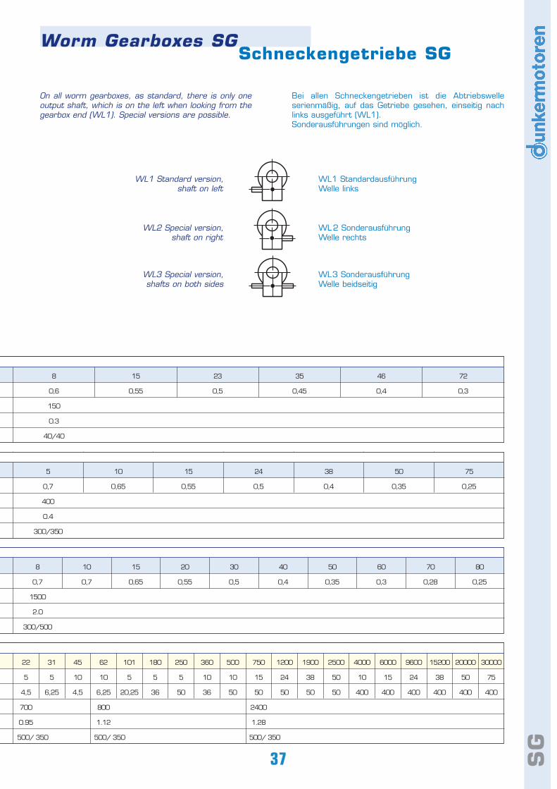
Bei allen Schneckengetrieben ist die Abtriebswelleserienmäßig, auf das Getriebe gesehen, einseitig nachlinks ausgeführt (WL1). Sonderausführungen sind möglich.
On all worm gearboxes, as standard, there is only oneoutput shaft, which is on the left when looking from thegearbox end (WL1). Special versions are possible.
WL1 StandardausführungWelle links
WL2 SonderausführungWelle rechts
WL3 SonderausführungWelle beidseitig
WL1 Standard version,shaft on left
WL2 Special version, shaft on right
WL3 Special version, shafts on both sides
SG
Worm Gearboxes SGSchneckengetriebe SG
37
22 31 45 62 101 180 250 360 500 750 1200 1900 2500 4000 6000 9600 15200 20000 30000
5 5 10 10 5 5 5 10 10 15 24 38 50 10 15 24 38 50 75
4,5 6,25 4,5 6,25 20,25 36 50 36 50 50 50 50 50 400 400 400 400 400 400
700 800 2400
0.95 1.12 1.28
500/ 350 500/ 350 500/ 350
8 10 15 20 30 40 50 60 70 80
0,7 0,7 0,65 0,55 0,5 0,4 0,35 0,3 0,28 0,25
1500
2.0
300/500
5 10 15 24 38 50 75
0,7 0,65 0,55 0,5 0,4 0,35 0,25
400
0.4
300/350
8 15 23 35 46 72
0,6 0,55 0,5 0,45 0,4 0,3
150
0.3
40/40
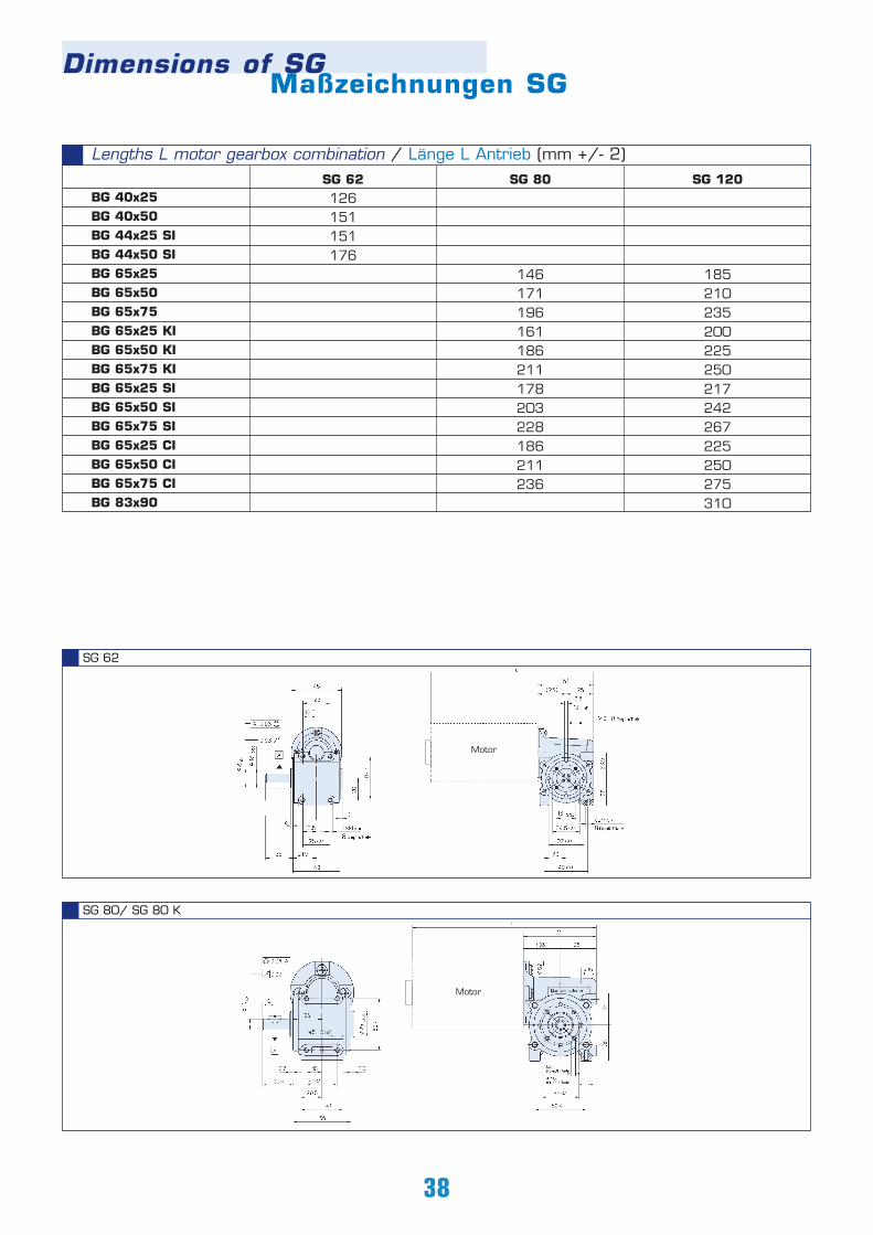
SG 80/ SG 80 K
SG 62
Lengths L motor gearbox combination / Länge L Antrieb (mm +/- 2)
BG 40x25BG 40x50BG 44x25 SIBG 44x50 SIBG 65x25BG 65x50BG 65x75BG 65x25 KIBG 65x50 KIBG 65x75 KIBG 65x25 SIBG 65x50 SIBG 65x75 SIBG 65x25 CIBG 65x50 CIBG 65x75 CIBG 83x90
SG 80
146171196161186211178203228186211236
SG 120
185210235200225250217242267225250275310
38
Motor
Motor
Dimensions of SGMaßzeichnungen SG
SG 62126151151176
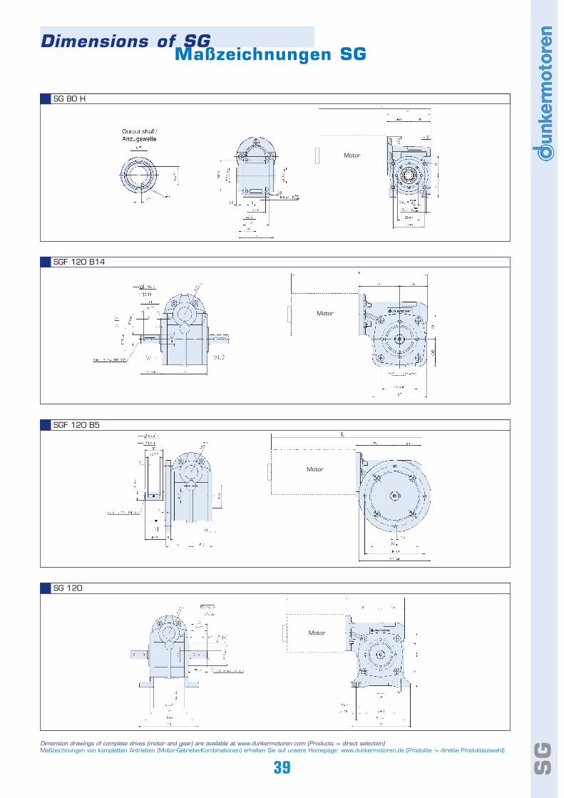
SG
SGF 120 B5
SGF 120 B14
SG 120
SG 80 H
Dimension drawings of complete drives (motor and gear) are available at www.dunkermotoren.com (Products -> direct selection)Maßzeichnungen von kompletten Antrieben (Motor-Getriebe-Kombinationen) erhalten Sie auf unsere Homepage: www.dunkermotoren.de (Produkte -> direkte Produktauswahl)
39
Motor
Motor
Motor
Motor
Dimensions of SGMaßzeichnungen SG

Bürstenlose Gleichstrommotoren der Baureihe BGkönnen mit Ankerstoppbremsen ausgerüstet werden. Eswerden standardmäßig Ruhestrombremsen geliefert,d. h. die Bremsung erfolgt wenn keine Spannung anliegtbzw. öffnet wenn Strom fließt. Arbeitsstrombremsensind auf Anfrage erhältlich. Für alle Bremsen sindSchutzhauben IP 54 erhältlich. Kombinationen vonInkrementalgebern und Bremsen sind möglich. Abhängigvon der Motor-Bremse-Kombination sind sogar Schutz-arten bis IP 65 möglich. Zum Schutz des Gleichstrom-kontaktes Ihrer Ansteuerung vor Kontaktabbrand wirdder Einsatz einer Freilaufdiode empfohlen.
E 38 RDie Federdruckbremse bremst im stromlosen Zustand.Durch die spezielle Konstruktion kann die Bremse sowohlals statische oder dynamische Bremse eingesetztwerden. Axiales Motorspiel hat keinen Einfluß auf dieBremsfunktion.
E 46 ADiese Arbeitsstrombremse ist nur auf Anfrage fürLosgrößen größer 500 Stück erhältlich.
E 90 RDie Federdruckbremse bremst im stromlosen Zustand.Durch die spezielle Konstruktion kann die Bremse sowohlals statische oder dynamische Bremse eingesetztwerden. Axiales Motorspiel hat keinen Einfluß auf dieBremsfunktion. Eine manuelle Entriegelung der Bremseist optional erhältlich (nicht bei Versionen mitSchutzhaube). In Kombination mit dem Motor BG 65kann die Bremse auch im Strangpressprofilgehäusegeliefert werden.
E 100 ADiese Arbeitsstrombremse (Permanentmagnetbremse)ist nur auf Anfrage erhältlich.
E 100 R Diese Ruhestrombremse (Permanentmagnetbremse)ist nur auf Anfrage erhältlich.
Bremsen für BG-Motoren
Brushless DC motors in the BG range can be fitted withrotor brakes. As standard, power-off brakes are em-ployed, i.e. the brake operates when no voltage isapplied and releases when current flows. Power-on brakes are available on request. IP 54 coversare available for all brakes. Combinations of incrementalencoders and brakes are possible. Depending on themotor-brake combination, degrees of protection up toIP 65 are possible. To protect the DC contacts in yourcontrol system against arcing, we recommend the useof a freewheeling diode.
E 38 RSpring-applied brake, operates when no current isapplied. The special design of this brake makes it suita-ble for both static and dynamic braking. Axial play in themotor has no influence on brake performance.
E 46 A This power-on brake is only available on request for bat-ches greater then 500 pieces.
E 90 RSpring-applied brake, operates when no current isapplied. The special design of this brake makes it suita-ble for both static and dynamic braking. Axial play in themotor has no influence on brake performance. Manualrelease of the brake is available as an option (not on ver-sions where a cover is fitted). In combination with motorBG 65, the brake can be incorporated in the extrudedmotor body.
E 100 AThis power-on brake (permanent-magnet brake) is onlyavailable on request.
E 100 R This power-off brake (permanent-magnet brake) is onlyavailable on request.
40
Brakes for BLDC Motors
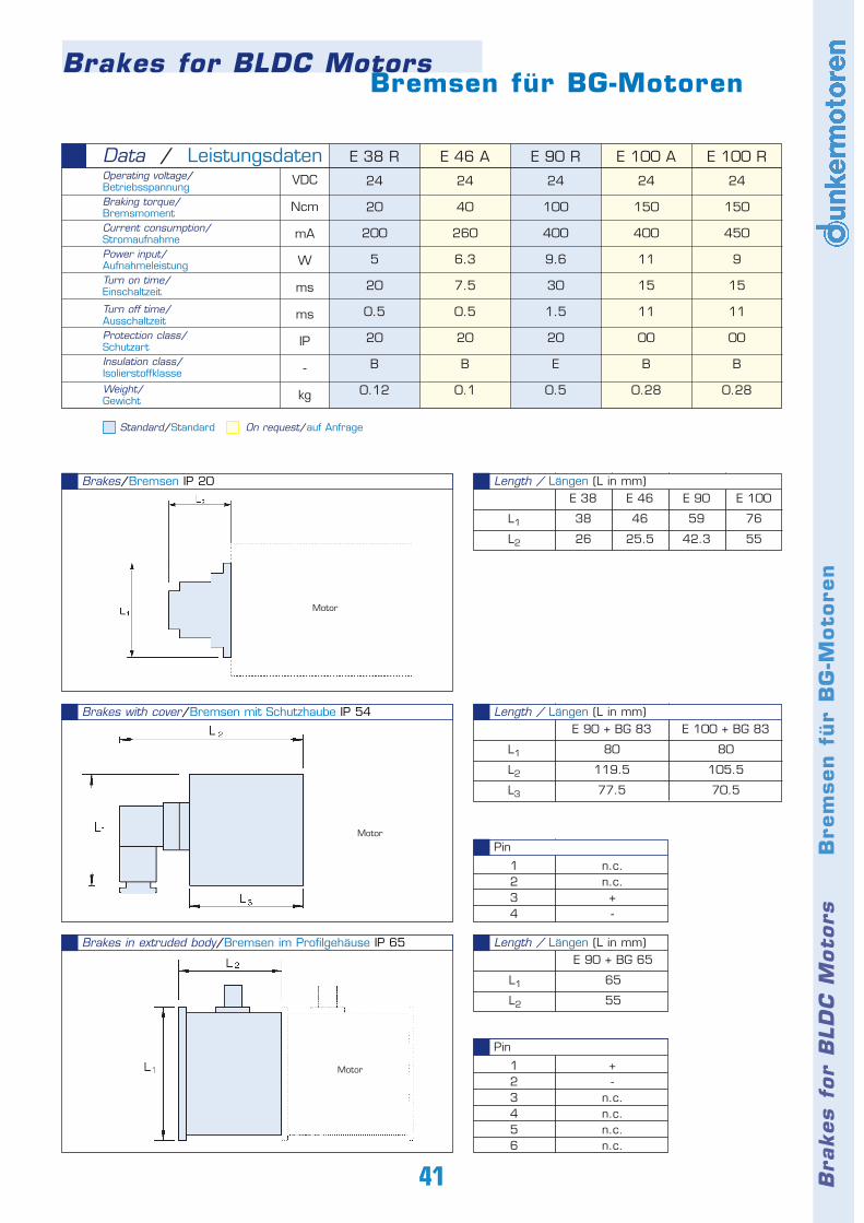
Bra
kes f
or
BLD
CM
oto
rs
B
rem
sen
für
BG
-Moto
ren
Bremsen für BG-Motoren
41
24
20
200
5
20
0.5
20
B
0.12
24
40
260
6.3
7.5
0.5
20
B
0.1
24
100
400
9.6
30
1.5
20
E
0.5
24
150
400
11
15
11
00
B
0.28
24
150
450
9
15
11
00
B
0.28
E 38 R E 46 A E 90 R E 100 A E 100 RData / LeistungsdatenOperating voltage/Betriebsspannung Braking torque/BremsmomentCurrent consumption/StromaufnahmePower input/AufnahmeleistungTurn on time/Einschaltzeit
Turn off time/AusschaltzeitProtection class/SchutzartInsulation class/Isolierstoffklasse
Weight/Gewicht
VDC
Ncm
mA
W
ms
ms
IP
-
kg
Brakes/Bremsen IP 20
Brakes with cover/Bremsen mit Schutzhaube IP 54
Brakes in extruded body/Bremsen im Profilgehäuse IP 65
L1
L2
E 38
38
26
E 46
46
25.5
E 90
59
42.3
E 100
76
55
Length / Längen (L in mm)
L1
L2
L3
E 90 + BG 83
80
119.5
77.5
E 100 + BG 83
80
105.5
70.5
Length / Längen (L in mm)
1234
n.c.n.c.+-
Pin
123456
+-
n.c.n.c.n.c.n.c.
Pin
E 90 + BG 65
65
55
Length / Längen (L in mm)
Motor
Motor
Motor
Brakes for BLDC Motors
Standard/Standard On request/auf Anfrage
L1
L2
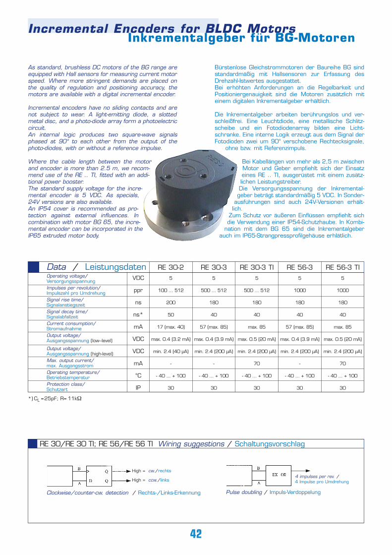
Bürstenlose Gleichstrommotoren der Baureihe BG sindstandardmäßig mit Hallsensoren zur Erfassung desDrehzahl-Istwertes ausgestattet. Bei erhöhten Anforderungen an die Regelbarkeit undPositioniergenauigkeit sind die Motoren zusätzlich miteinem digitalen Inkrementalgeber erhältlich.
Die Inkrementalgeber arbeiten berührungslos und ver-schleißfrei. Eine Leuchtdiode, eine metallische Schlitz-scheibe und ein Fotodiodenarray bilden eine Licht-schranke. Eine interne Logik erzeugt aus dem Signal derFotodioden zwei um 90° verschobene Rechtecksignale,
ohne bzw. mit Referenzimpuls.
Bei Kabellängen von mehr als 2,5 m zwischenMotor und Geber empfiehlt sich der Einsatzeines RE .. TI, ausgerüstet mit einem zusätz-lichen Leistungstreiber. Die Versorgungsspannung der Inkremental-geber beträgt standardmäßig 5 VDC. In Sonder-
ausführungen sind auch 24V-Versionen erhält-lich.
Zum Schutz vor äußeren Einflüssen empfiehlt sichdie Verwendung einer IP54-Schutzhaube. In Kombi-
nation mit dem BG 65 sind die Inkrementalgeberauch im IP65-Strangpressprofilgehäuse erhlätlich.
Incremental Encoders for BLDC MotorsInkrementalgeber für BG-Motoren
As standard, brushless DC motors of the BG range areequipped with Hall sensors for measuring current motorspeed. Where more stringent demands are placed onthe quality of regulation and positioning accuracy, themotors are available with a digital incremental encoder.
Incremental encoders have no sliding contacts and arenot subject to wear. A light-emitting diode, a slottedmetal disc, and a photo-diode array form a photoelectriccircuit. An internal logic produces two square-wave signalsphased at 90° to each other from the output of thephoto-diodes, with or without a reference impulse.
Where the cable length between the motorand encoder is more than 2.5 m, we recom-mend use of the RE .. TI, fitted with an addi-tional power booster. The standard supply voltage for the incre-mental encoder is 5 VDC. As specials,24V versions are also available. An IP54 cover is recommended as pro-tection against external influences. Incombination with motor BG 65, the incre-mental encoder can be incorporated in theIP65 extruded motor body.
42
RE 30-2
5
100 ... 512
200
50
17 (max. 40)
max. 0.4 (3.2 mA)
min. 2.4 (40 µA)
-
- 40 ... + 100
30
5
500 ... 512
180
40
57 (max. 85)
max. 0.4 (3.9 mA)
min. 2.4 (200 µA)
-
- 40 ... + 100
30
5
500 ... 512
180
40
max. 85
max. 0.5 (20 mA)
min. 2.4 (200 µA)
70
- 40 ... + 100
30
5
1000
180
40
57 (max. 85)
max. 0.4 (3.9 mA)
min. 2.4 (200 µA)
-
- 40 ... + 100
30
5
1000
180
40
max. 85
max. 0.5 (20 mA)
min. 2.4 (200 µA)
70
- 40 ... + 100
30
RE 30-3 RE 30-3 TI RE 56-3 RE 56-3 TIData / LeistungsdatenOperating voltage/VersorgungsspannungImpulses per revolution/Impulszahl pro UmdrehungSignal rise time/SignalanstiegszeitSignal decay time/SignalabfallzeitCurrent consumption/StromaufnahmeOutput voltage/Ausgangsspannung (low--level)
Output voltage/Ausgangsspannung (high-level)Max. output current/max. AusgangsstromOperating temperature/BetriebstemperaturProtection class/Schutzart
VDC
ppr
ns
ns*
mA
VDC
VDC
mA
°C
IP
Pulse doubling / Impuls-Verdoppelung
4 impulses per rev. /4 Impulse pro Umdrehung
RE 30/RE 30 TI; RE 56/RE 56 TI Wiring suggestions / Schaltungsvorschlag
Clockwise/counter-cw. detection / Rechts-/Links-Erkennung
High = cw./rechts
High = ccw./links
*) CL =25pF; R= 11kΩ
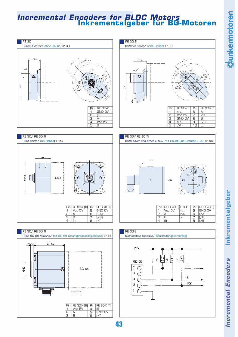
Incremental Encoders for BLDC MotorsInkrementalgeber für BG-Motoren
43
RE 30
(without cover/ ohne Haube) IP 30
RE 30 TI
(without cover/ ohne Haube) IP 30
RE 30/ RE 30 TI
(with cover/ mit Haube) IP 54
RE 30/ RE 30 TI
(with cover and brake E 90/ mit Haube und Bremse E 90) IP 54
RE 30-3
(Connection example/ Beschaltungsvorschlag)
RE 30/ RE 30 TI
(with BG 65 housing/ mit BG 65 Strangpressprofilgehäuse) IP 65
Incr
em
enta
l E
nco
ders
Inkre
men
talg
eber
BG 65
RE 30-XGND 0V(I)AVcc 5VB
Pin678910
Pin12345
RE 30-X TIA/BB(/I)(I)
RE 30-X TIn.c.Vcc 5VGND 0Vn.c./A
Pin12345
Pin5678
Pin1234
RE 30-X (TI)GND 0V(/A)(/B)(/I)
RE 30-X (TI)Vcc 5VAB(I)
Pin5678
Pin1234
RE 30-X (TI)GND 0V(/A)(/B)(/I)
RE 30-X (TI)Vcc 5VAB(I)
E 90n.c.n.c.+ -
Pin456
Pin123
RE 30-X (TI)(I)GND 0V(/I)
RE 30-X (TI) Vcc 5VAB
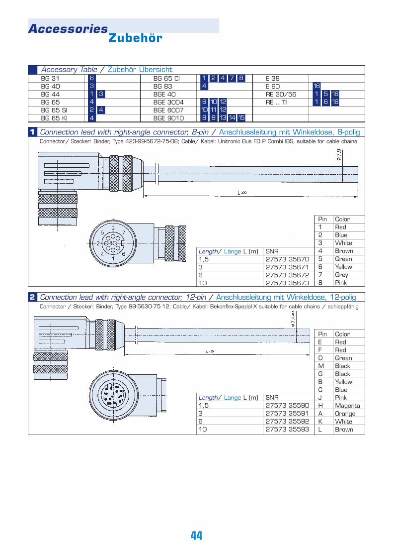
4
AccessoriesZubehör
44
Accessory Table / Zubehör ÜbersichtBG 31BG 40BG 44BG 65BG 65 SIBG 65 KI
BG 65 CIBG 83BGE 40BGE 3004BGE 6007BGE 9010
E 38E 90RE 30/56RE .. TI
Length/ Länge L (m)1,53610
SNR27573 3567027573 3567127573 3567227573 35673
Pin12345678
ColorRedBlueWhiteBrownGreenYellowGreyPink
1
Connection lead with right-angle connector, 12-pin / Anschlussleitung mit Winkeldose, 12-poligConnector / Stecker: Binder, Type 99-5630-75-12; Cable/ Kabel: Bekonflex-Spezial-X suitable for cable chains / schleppfähig
Length/ Länge L (m)1,53610
SNR27573 3559027573 3559127573 3559227573 35593
PinEFDMGBCJHAKL
2
3
33
4
14
1 2 7 8
6 10 12
4
10 11 128 9 13 14 15
161 5 161 6 16
ColorRedRedGreenBlackBlackYellowBluePinkMagentaOrangeWhiteBrown
Connection lead with right-angle connector, 8-pin / Anschlussleitung mit Winkeldose, 8-poligConnector/ Stecker: Binder, Type 423-99-5672-75-08; Cable/ Kabel: Unitronic Bus FD P Combi IBS, suitable for cable chains
6
2
4
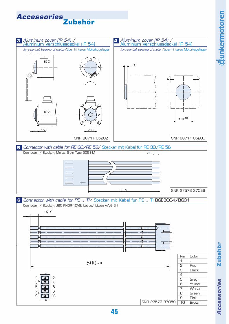
Acc
essori
es
Z
ubeh
ör
AccessoriesZubehör
45
Aluminum cover (IP 54) / Aluminium Verschlussdeckel (IP 54)for rear ball bearing of motor/über hinteres Motorkugellager
3 Aluminum cover (IP 54) / Aluminium Verschlussdeckel (IP 54)for rear ball bearing of motor/über hinteres Motorkugellager
4
Connector with cable for RE .. TI/ Stecker mit Kabel für RE .. TI BGE3004/BG31Connector / Stecker: JST, PHDR-10VS; Leads/ Litzen AWG 24
6
5 Connector with cable for RE 30/RE 56/ Stecker mit Kabel für RE 30/RE 56Connector / Stecker: Molex, 5-pin Type 5051-M
Pin12345678910
Color-RedBlack-GreyYellowWhiteGreenPinkBrown
SNR 88711 05202 SNR 88711 05200
SNR 27573 37026
SNR 27573 37059
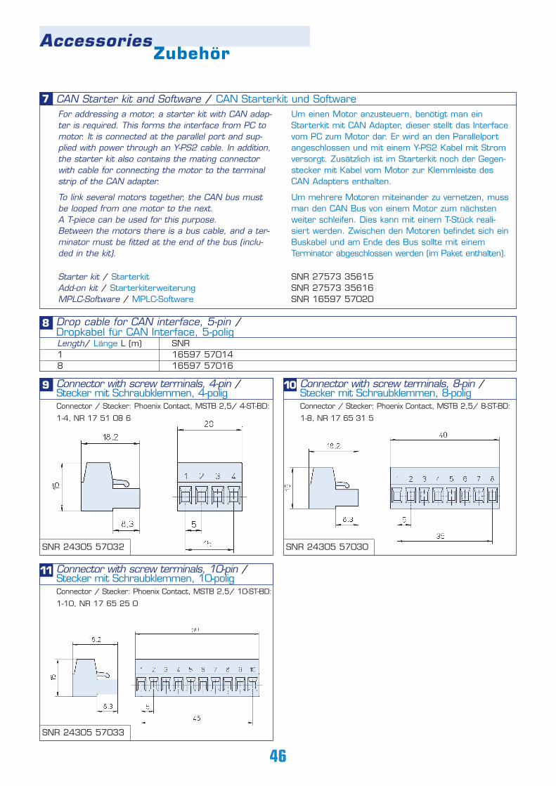
AccessoriesZubehör
46
CAN Starter kit and Software / CAN Starterkit und SoftwareFor addressing a motor, a starter kit with CAN adap-ter is required. This forms the interface from PC tomotor. It is connected at the parallel port and sup-plied with power through an Y-PS2 cable. In addition,the starter kit also contains the mating connectorwith cable for connecting the motor to the terminalstrip of the CAN adapter.
To link several motors together, the CAN bus mustbe looped from one motor to the next. A T-piece can be used for this purpose. Between the motors there is a bus cable, and a ter-minator must be fitted at the end of the bus (inclu-ded in the kit).
Um einen Motor anzusteuern, benötigt man einStarterkit mit CAN Adapter, dieser stellt das Interfacevom PC zum Motor dar. Er wird an den Parallelportangeschlossen und mit einem Y-PS2 Kabel mit Stromversorgt. Zusätzlich ist im Starterkit noch der Gegen-stecker mit Kabel vom Motor zur Klemmleiste desCAN Adapters enthalten.
Um mehrere Motoren miteinander zu vernetzen, mussman den CAN Bus von einem Motor zum nächstenweiter schleifen. Dies kann mit einem T-Stück reali-siert werden. Zwischen den Motoren befindet sich einBuskabel und am Ende des Bus sollte mit einemTerminator abgeschlossen werden (im Paket enthalten).
7
Drop cable for CAN interface, 5-pin / Dropkabel für CAN Interface, 5-poligLength/ Länge L (m)18
SNR16597 5701416597 57016
8
Starter kit / Starterkit SNR 27573 35615Add-on kit / Starterkiterweiterung SNR 27573 35616MPLC-Software / MPLC-Software SNR 16597 57020
SNR 24305 57032
SNR 24305 57033
SNR 24305 57030
Connector with screw terminals, 4-pin / Stecker mit Schraubklemmen, 4-poligConnector / Stecker: Phoenix Contact, MSTB 2,5/ 4-ST-BD:
1-4, NR 17 51 08 6
9 Connector with screw terminals, 8-pin / Stecker mit Schraubklemmen, 8-poligConnector / Stecker: Phoenix Contact, MSTB 2,5/ 8-ST-BD:
1-8, NR 17 65 31 5
10
Connector with screw terminals, 10-pin / Stecker mit Schraubklemmen, 10-poligConnector / Stecker: Phoenix Contact, MSTB 2,5/ 10-ST-BD:
1-10, NR 17 65 25 0
11
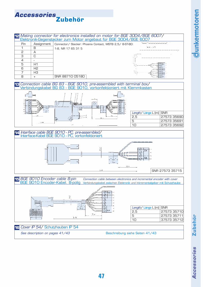
Acc
essori
es
Z
ubeh
ör
AccessoriesZubehör
47
Cover IP 54/ Schutzhauben IP 5416See description on pages 41/43 Beschreibung siehe Seiten 41/43
Mating connector for electronics installed on motor for BGE 3004/BGE 6007/Elektronik-Gegenstecker zum Motor angebaut für BGE 3004/BGE 6007
Connector/ Stecker: Phoenix Contact, MSTB 2,5/ 8-ST-BD:
1-8, NR 17 65 31 5
12
SNR 88710 05180
Interface cable BGE 9010 - PC, pre-assembled/ Interface-Kabel BGE 9010 - PC, vorkonfektioniert
14
SNR 27573 35715
BGE 9010 Encoder cable 8-pin Connection cable between electronics and incremental encoder with coverBGE 9010 Encoder-Kabel. 8-polig Verbindungskabel zwischen Elektronik und Inkrementalgeber mit Schutzhaube
15
SNR27573 3571027573 3571137573 35712
Length/ Länge L (m)2,5510
Connection cable BG 83 - BGE 9010, pre-assembled with terminal box/Verbindungskabel BG 83 - BGE 9010, vorkonfektioniert mit Klemmkasten
SNR27573 3569027573 3569127573 35692
13
Length/ Länge L (m)2,5510
Pin12345678
AssignmentBAC-H1H2H3+

NotesNotizen
48
Note
s
N
oti
zen
NotesNotizen
49
REPRESENTATIVES AND DISTRIBUTORS
Sachsen, Thüringen, Sachsen-Anhalt Spezialantriebstechnik GmbH Roland KühnelFröndenberger Str. 13 · 04746 HarthaTel. (034328) 661 0 · Fax (034328) 661 10e-mail: [email protected]: www.spat-antriebe.de
Niedersachsen,Hessen Nord, Westfalen Ost Ingenieurbüro Heinrich JürgensRoggenhof 5 · 31787 HamelnTel. (05158) 98098 · Fax (05158) 98099e-mail: [email protected]
Hamburg/Bremen,Schleswig- Holstein,Niedersachsen Nord Technisches Büro Kühling/MertenRedder 1 B · 22393 HamburgTel. (040) 5234098 · Fax (040) 5282476e-mail: [email protected]: www.kuehling-merten.de
Ruhrgebiet Lothar AmbornFasanenstrasse 21b · 45134 Essen-StadtwaldTel. (0201) 443500 · Fax (0201) 443501e-mail: [email protected]
RheinlandATS SchloteIn der Brückenwiese · 53639 KönigswinterTel. (02244) 918178 Tel. Mobil (0173) 8920690Fax (02244) 918171e-mail: [email protected]
Hessen Antriebstechnik Eberhardt GmbHLandgrabenstrasse 21 · 61118 Bad VilbelTel. (06101) 500316Fax (06101) 500318e-mail: [email protected]/eberhardt
Rheinland-Pfalz, SaarlandDieter BremsBurgunder Strasse 35 · 55278 MommenheimTel. (06138) 1366 · Fax (06138) 1335e-mail: [email protected]
Bayern Nord Ingenieurbüro für Elektrotechnik GmbHDipl.-Ing. ChristlevenPreuschwitzerstr. 38 · 95445 BayreuthTel. (0921) 41360 · Fax (0921) 46192e-mail: [email protected]: www.christleven.de
Bayern Süd Antriebstechnik Quin GmbHHerr Ferdinand QuinLärchenstrasse 1 · 85604 ZornedingTel. (08106) 247170 · Fax (08106) 247171e-mail: [email protected] · Internet: www.atq.de
Württemberg Technisches Büro SpäthEyachstrasse 37 · 71065 SindelfingenTel. (07031) 794 34-60 · Fax (07031) 794 34-70e-mail: [email protected]: www.spaeth-technik.de
Baden Büro für AntriebstechnikFrieder HertweckMooswaldstr. 8 · 79279 VörstettenTel. (07666) 4188 · Fax (07666) 7343e-mail: [email protected]
AustriaIng. Franz Schmachtl KGPostfach 362 · Pummererstrasse 36 · 4021 LinzTel. (0732) 76460 · Fax (0732) 785036www.schmachtl.ate-mail: [email protected]
Ing. Franz Schmachtl KGTheodor-Körner-Strasse 54 · 8010 GrazTel. (0316) 672185 · Fax (0316) 672439e-mail: [email protected]
Ing. Franz Schmachtl KGHöttinger Au 20 · 6020 InnsbruckTel. (0512) 265060-0 · Fax (0512) 266151e-mail: [email protected]
Ing. Franz Schmachtl KGPostfach 187 · 1230 WienTel. (01) 6162180 · Fax (01) 616218099e-mail: [email protected]
Belgium / LuxembourgElmeq B.V.B.A.Industrial Zone Beveren-NoordOnledegoedstraat 79 · 8800 RoeselareTel. (051) 25 98 11 · Fax (051) 25 98 18e-mail: [email protected] · Internet: www.elmeq.be
Czech RepublikSchmachtl CZ s.r.o.Vestec 185 · 25242 JeseniceTel. (02) 44 00 15 00 · Fax (02) 44 91 07 00www.schmachtl.cz · e-mail: [email protected]
DenmarkCompower A/SSmedeholm 13A · 2730 HerlevTel. 44926620 · Fax 44926602 · Mobile 20836620 e-mail: [email protected] Internet: http://www.compower.dk
FinlandWexon OYJuhanilantie 4 · 01740 VantaaTel. (09) 290 440 · Fax (09) 290 44100e-mail: [email protected] · Internet: www.wexon.fi
FranceMDP21 Porte du Grand Lyon, Neyron01707 Miribel CédexTel. (4)72 018300 · Fax (4)72 018309e-mail: [email protected]: www.mdpmotor.com
Great BritainAlcatel Dunkermotoren, Div. of AVTSpringfield House · 23 Oatlands DriveGB-Weybridge, Surrey · KT13 9LYTel. (01932) 240 531 · Fax (01932) 244 302e-mail: [email protected]: www.dunkermotoren.com
IsraelAvi Sasson RepresentativesP.O. Box 927061091 Tel AvivTel. (03) 5015322 · Fax (03) 5031986e-mail: [email protected]
ItalySPII S.p.A.Via Volpi 37 · 21047 Saronno (VA)Tel. (02) 9622921 · Fax (02) 9609611e-mail: [email protected] · Internet: www.spii.it
KoreaAlcatel Dunkermotoren Div. of AVTK4.Floor, SunghyunB/D, 10-5, Karak-Dong, Songpa-Ku, SeoulMobile: 82 19309 6277 Fax (02) 409-6279e-mail: [email protected]
NetherlandsElmeq Nederland B.V.Broeikweg 25 · 2871 RM SchoonhovenTel. (0182) 30 34 56 · Fax (0182) 38 69 20e-mail: [email protected] · www.elmeq.nl
NorgeStork ASBrynsveien 100 · 1352 KolsåsTel. 67176400 · Fax 67176401Mobile: 46 706 276 023e-mail: [email protected]
PolandP.P.H. WOBITWitold Ober ul. Gruszkowa 4 PL 61-474 PoznanTel. (48) 61 835 08 00 · Fax (48) 61 835 [email protected] · www.wobit.pl
SlovakiaSchmachtl SK, s.r.o.Dumbierska 10/A · 831 01 BratislavaTel. 02 54789293 · Fax 02 54772147www.schmachtl.sk · e-mail: [email protected]
SpainElmeq S.L.(Gran Via Center)C/ Vilamarí 50, 3° A y B08015 BarcelonaTel. (93) 422 7033 · Fax (93) 4323660e-mail: [email protected]
SwedenDJ Stork Drives ABBox 1037 · Vretenvägen 4-6, Solna SE-172 21 Sundbyberg Tel. (08) 635 60 00 · Fax (08) 635 60 01www.storkdrives.se · e-mail: [email protected]
Switzerland PLZ 1, 2, 3, 45Dipl. El. Ing. HTL Hans Ruedi IselinHaselweg 3 · 2553 Safnern/Biel Tel. (032) 355 33 79 · Fax (032) 355 27 29e-mail: [email protected]
PLZ 6, 7, 87-88, 9Ivo MittagRebbergstr. 49 · 8049 ZürichTel. (01) 342 11 29 · Fax (01) 342 14 79e-mail: [email protected]
United States of AmericaAlcatel DunkermotorenDivision of AVP 2 Park Central Drive - Suite 120MA 01772 Southborough Tel. (508) 786 0786 · Fax (508) 786 0726e-mail: [email protected]
Alcatel DunkermotorenDivision of AVP Mr. Bob Ransom5850 Potomac Dr.NC 28027 ConcordTel. (704) 720 9396 · Fax (704) 720 9397e-mail: [email protected]
Alcatel DunkermotorenDivision of AVP Mr Roger Postolka32924 Danapoplar CA 92629 Dana PointTel. (949) 661 8747 · Fax (949) 661 8748e-mail: [email protected]
Alcatel DunkermotorenDivision of AVP7105 Virginia Rd, Suite 14IL 60014 Crystal LakeTel. (815) 356 1576 · Fax (815) 356 2760e-mail: [email protected]
EUROPE AND OVERSEESGERMANY
Alcatel SEL AG · Components DivisionDunkermotoren · Allmendstraße 11D-79848 Bonndorf/Schwarzwald
www.dunkermotoren.com · [email protected] +49 (0) 7703 930-0 · Fax +49 (0) 7703 930-210/212