VASIMR Extension Design - Worcester Polytechnic … 3.3.5 Material Selection and Optimization 42 3.4...
98
1 VASIMR ISS Extension Design Major Qualifying Project Gabriel Louzao 3/3/2011 A Major Qualifying Project submitted to the Faculty of Worcester Polytechnic Institute and Ad Astra Rocket Company as a partial fulfillment of the requirements for the Degree of Bachelor of Science in Mechanical Engineering
Transcript of VASIMR Extension Design - Worcester Polytechnic … 3.3.5 Material Selection and Optimization 42 3.4...
1
VASIMR ISS Extension
Design Major Qualifying Project
Gabriel Louzao
3/3/2011
A Major Qualifying Project submitted to the Faculty of Worcester Polytechnic Institute and Ad Astra Rocket Company as a partial fulfillment of the requirements for the Degree of Bachelor of Science in Mechanical Engineering

i
Abstract
The Variable Specific Impulse Magnetoplasma Rocket, developed by Ad Astra Rocket Company is
an advanced plasma propulsion technology which will be attached to the International Space Station in
2014 to serve as the main thrust device to counteract atmospheric drag. This project covers the first
iteration of a design for this structure, including all of its sub components, which have been tested to
support launch and operation forces. The assembly components, over 200 of them, were all individually
tested using Finite Element Analysis. The completed structure fits inside the Taurus II commercial rocket,
and complies with all requirements set by both Ad Astra Rocket Company and space engineering
handbook standards. In addition, a 1/10th scale model of the assembly was constructed for exhibition
in the lab and various thermal and structural tests were performed on site to aid in the development of
the VASIMR engine. A guide to migrating thermal data for structural testing in Pro Engineer was
developed as well.

ii
Executive Summary
Ad Astra Rocket Company is a private spaceflight engineering company dedicated to the
development of advanced plasma rocket propulsion technology. They have two laboratories, one
located in Houston, Texas, and the other one located in Liberia, Costa Rica. They have developed the
Variable Specific Impulse Magnetoplasma Rocket (VASIMR), an advanced plasma engine which uses
ionized gas to produce thrust. The engine is the result of almost thirty years of development by its
inventor Dr. Franklin Chang Díaz.
VASIMR will be attached to the International Space Station (ISS) in 2014 to serve as the main
thrust device to counteract the stations atmospheric drag. It will be launched in a commercial rocket
and must fit inside its limited cargo space. Once in space, it must extend a distance of over sixteen
meters with its radiators deployed, in order to properly position it for operation. The assembly will be
attached to the Z1 truss structure on the ISS and consists of an expandable truss device, the VASIMR bay
where all Orbital Replacement Units (ORU) are housed and a thirty two meter surface area extending
radiator. While the development of the plasma engine is almost complete, the creation and testing of
this structure is in its preliminary phases.
This project covers the first iteration of a design for this structure, including all of its sub
components, which have been tested to support launch and operation forces. The assembly
components, over 200 of them, were all individually tested using Finite Element Analysis, specifically the
Pro Engineer/Mechanica software. The completed structure fits inside the Taurus II commercial rocket,
and complies with all initial requirements set by both Ad Astra Rocket Company and space engineering
handbook standards. In addition, a 1/10th scale model of the assembly was constructed for exhibition in
the lab using hardware store bought materials. Finally, various thermal and structural tests were

iii
performed on site to aid in the development of the VASIMR engine and a guide to migrating thermal
data for structural tests in Pro Engineer was created.

iv
Acknowledgements
I first want to thank all of the staff at Ad Astra Liberia for their continuous help and support
throughout the project. Not only did they help me, but made me a member of their team, delegating
responsibility to me, and including me in their day to day work. I want to personally thank Jorge Oguilve,
as he supervised me directly and taught me about structural tests, Pro Engineer and various lab
activities. Finally I want to thank my advisor professor Eben Cobb for his support and direction
throughout the project.

v
Table of Contents
Abstract .......................................................................................................................................................... i
Executive Summary ....................................................................................................................................... ii
Acknowledgements ...................................................................................................................................... iv
Table of Contents .......................................................................................................................................... v
Table of Figures ............................................................................................................................................ ix
1. Introduction .............................................................................................................................................. 1
2. Background ............................................................................................................................................... 2
2.1 VASIMR................................................................................................................................................ 2
2.2 Taurus II Launch Vehicle ..................................................................................................................... 5
2.3 Design and Considerations for Space Structures ................................................................................ 8
2.3.1 Space Environment ...................................................................................................................... 8
2.3.2 Typical Design Process ............................................................................................................... 10
2.3.3 Materials .................................................................................................................................... 12
2.3.4 Mechanisms ............................................................................................................................... 14
2.3.5 Structural Analysis and the use of Finite Element Models ........................................................ 15
2.4 Major Concepts used in Pro Mechanica ........................................................................................... 17
2.4.1 Stress .......................................................................................................................................... 17
2.4.2 Displacement and Strain Energy ................................................................................................ 18
2.4.3 Convergence .............................................................................................................................. 19

vi
2.5 The International Space Station ........................................................................................................ 21
2.5.1 Electrical Power System ............................................................................................................. 22
2.5.2 Thermal Control System............................................................................................................. 23
2.6 Finite Element Analysis in Pro/Mechanica........................................................................................ 24
2.6.1 Experiment Design ..................................................................................................................... 24
2.6.2 Materials and Equipment........................................................................................................... 25
2.6.3 Experimental Setup .................................................................................................................... 25
2.6.4 Experimental Procedure ............................................................................................................ 28
2.6.5 Mathematical Calculations ........................................................................................................ 29
2.6.6 Pro Engineer Model ................................................................................................................... 30
2.6.7 Results ........................................................................................................................................ 31
2.7 Extra Background Research .............................................................................................................. 33
3. VASIMR ISS Extension Device .................................................................................................................. 34
3.1 Introduction ...................................................................................................................................... 34
3.2 General Requirements ...................................................................................................................... 34
3.3 Truss Structure Design ...................................................................................................................... 36
3.3.1 Requirements ............................................................................................................................. 36
3.3.2 Research, Motion Analysis and Changes in Original Design ...................................................... 36
3.3.3 Truss Orientation ....................................................................................................................... 37
3.3.4 Truss Cross Section Analysis....................................................................................................... 41

vii
3.3.5 Material Selection and Optimization ......................................................................................... 42
3.4 VASIMR Bay Design ........................................................................................................................... 45
3.4.1 Requirements ............................................................................................................................. 45
3.4.2 Structural Frame Design ............................................................................................................. 46
3.4.3 Orbital Replacement Units ......................................................................................................... 48
3.4.4 VASIMR Interphase Design ........................................................................................................ 49
3.4.5 Covers, Cabling and Other Items ............................................................................................... 50
3.5 Radiator Design ................................................................................................................................. 51
3.5.1 Requirements ............................................................................................................................. 51
3.5.2 Design Process ........................................................................................................................... 53
3.6 Orbital Replacement Unit Design ..................................................................................................... 58
3.6.1 Requirements ............................................................................................................................. 59
3.6.2 ORU Design ................................................................................................................................ 60
3.7 Payload Fairing Design ...................................................................................................................... 65
3.7.1 Design Requirements ................................................................................................................. 65
3.7.2 Design and Testing ..................................................................................................................... 66
4. Thermal Data Migration from Thermal Desktop to Pro Mechanica ....................................................... 69
4.1 What is an FNF file? .......................................................................................................................... 69
4.2 FNF creation and implementation .................................................................................................... 70
5. Conclusions ............................................................................................................................................. 74

viii
References .................................................................................................................................................. 76
Appendix ..................................................................................................................................................... 78
DVD Navigation ....................................................................................................................................... 78
A.1 Taurus II ............................................................................................................................................ 79
A.2 Displacement Test Results ................................................................................................................ 79
A.3 Beam Truss Structure Results ........................................................................................................... 80
A.4 ORU ................................................................................................................................................... 81
A.5 Scale Model Construction ................................................................................................................. 82

ix
Table of Figures
Figure 1: Schematic of the VASIMR Engine (NASA, 2010) ............................................................................ 3
Figure 2: A photograph of the VX-200 operating at full power with argon propellant (Ad Astra Rocket
Company, 2010) ............................................................................................................................................ 4
Figure 3: Taurus II Launch Vehicle (Orbital, 2010). ....................................................................................... 5
Figure 4: RUAG 1666 VS Payload Mechanical Interphase (Orbital, 2010). .................................................. 6
Figure 5: Typical structural design process (Library of Flight, 2009, p. 204) .............................................. 10
Figure 6: Wax motor acting as a pin puller (Library of Flight, 2009, p. 225) .............................................. 14
Figure 7: Pro Mechanica test design (Toogood, 2004) ............................................................................... 16
Figure 8: Typical Pro Mechanica Result Window ........................................................................................ 17
Figure 9: Convergence results for a standard test ...................................................................................... 20
Figure 10: ISS Configuration (NASA, 2007) ................................................................................................. 21
Figure 11: Simple beam deflection calculation (www.engineersedge.com, 2011) .................................... 24
Figure 12: Beam Dimensions for the experimental setup .......................................................................... 25
Figure 13: Complete test setup with arrow pointing at galvanized strip ................................................... 26
Figure 14: Complete experimental setup with digital readout marking 0kN and dial micrometer marking
0mm ............................................................................................................................................................ 27
Figure 15: Test Results 1-4kN ...................................................................................................................... 28
Figure 16: 5kN and maximum force (5.7kN) tests ...................................................................................... 29
Figure 17: Experimental setup showing constraints, loads and beam elements ....................................... 30
Figure 18: Beam bending under 1kN loading, with deflections scaled by 10% .......................................... 31
Figure 19: Taurus II cargo space (Orbital, 2010), and calculations for sides of the box. ............................ 37
Figure 20: Simple Truss geometry............................................................................................................... 38
Figure 21: Beam Orientation Design 1 ........................................................................................................ 38

x
Figure 22: Von Mises Stress results for design 1 ........................................................................................ 39
Figure 23: Von Mises stress visualization of final design ............................................................................ 40
Figure 24: Young’s Modulus/Density with all materials ............................................................................. 43
Figure 25: Density* Price graph .................................................................................................................. 43
Figure 26: Original Bay Design .................................................................................................................... 45
Figure 27: Bay preliminary dimensions, and channel dimensions .............................................................. 47
Figure 28: Final VASIMR bay structure ....................................................................................................... 48
Figure 29: VASIMR interphase final design ................................................................................................. 49
Figure 30: Assorted VASIMR bay pictures ................................................................................................... 50
Figure 31: VASIMR Extension Assembly with space left for radiator mechanism ...................................... 52
Figure 32: Closed Radiator Final Design ...................................................................................................... 53
Figure 33: Radiator Plate and Channel Cross Section ................................................................................. 54
Figure 34: Final Panel Construction with tubing included .......................................................................... 55
Figure 35: Radiator Scissor Mechanism ...................................................................................................... 56
Figure 36: Fully extended radiator. ............................................................................................................. 56
Figure 37: Radiator Housing in closed and extended positions. ................................................................. 57
Figure 38: Astronaut performing maintenance on the ISS (NASA, 2010) ................................................... 58
Figure 39: ORU housed inside the enclosure .............................................................................................. 60
Figure 40: ORU Back Plate design, Close up of electrical and thermal connections .................................. 61
Figure 41: Inside compartments of ORU unit, right side shows lateral view with cabling and copper tubes
.................................................................................................................................................................... 62
Figure 42: Detailed view of cabling and copper tubing .............................................................................. 62
Figure 43: Full locking mechanism and close up of shaft, tube, key and spring devices in mechanism. ... 63
Figure 44: Mechanism with guiding cover and the mechanism with its key inserted into the key hole ... 64

xi
Figure 45: Standard mechanical interphase Taurus II Rocket (Orbital, 2010) ............................................ 65
Figure 46: First Payload Fairing Design ....................................................................................................... 66
Figure 47: Loaded Payload Fairing .............................................................................................................. 67
Figure 48: Various Views of the payload fairing ......................................................................................... 68
Figure 49: Meshed Cylinder with Pro/Engineer’s mesh options set to automatic ..................................... 69
Figure 50: Meshed Simple Cylinder ............................................................................................................ 70
Figure 51: Pro/Mechanica popup with FEM Mode checked. ..................................................................... 71
Figure 52: Meshed Cylinder in FEM Mode .................................................................................................. 71
Figure 53: FNF Creation Options ................................................................................................................. 72
Figure 54: Load Section Format (PTC, 2010) ............................................................................................... 73
Figure 55: Front and back of the first box ................................................................................................... 83
Figure 56: Alignment assembly with close up............................................................................................. 83
Figure 57: Drilled holes and completed box assembly ............................................................................... 83
Figure 58: Assortment of pictures showing the process of beam flattening and the finalized box design 83
Figure 59: Rail attachment process, clearances and final design ............................................................... 83
Figure 60: Scale model construction ........................................................................................................... 83
1
1. Introduction
Ad Astra Rocket Company (AARC) is a private spaceflight engineering company dedicated to
developing advanced plasma rocket propulsion technology (Ad Astra Rocket Company, 2011). It is
developing the Variable Specific Impulse Magnetoplasma Rocket (VASIMR), a rocket engine which uses
ionized gas and converts it to plasma, thus creating thrust. Ad Astra has two laboratories, one located in
Houston, Texas and the other one located in Liberia, Costa Rica. The company is led by Dr. Franklin R.
Chang Díaz, who invented the VASIMR concept and has been developing it since 1979.
Ad Astra has advanced the development of the VASIMR to a point where it will be space ready in
by 2014, and will send the engine to the International Space Station to serve as the main rocket booster,
attached to the z1 truss (Ad Astra Rocket Company, 2010). The structure that will be launched includes
two VASIMR engines, a radiator, and a truss section to position the engine at the correct location. The
engine will be launched in a commercial rocket, which limits the size of the structure to the rocket’s
cargo bay. In order to make the structure as small as possible, a drawer like mechanism will be used.
While Ad Astra has gone far in developing the VASIMR, it has not yet designed the extension
device and the related mechanisms. Ad Astra is currently developing a full scale mockup of the structure
but only to serve as an exhibition piece, and has not tested the structure to make sure it can handle the
launch and operation forces. Ad Astra has allowed me to design the first iteration of the structure,
following the geometric constraints set forth in the Design Requirement Document (DRD) for the
mockup project. My goal was to design the structure and related mechanisms, create a 1/10 scale model
made out of materials available at a hardware store, and help Ad Astra with the migration of thermal
data from their thermal analysis program to Pro/Engineer.

2
2. Background
This project deals with the design of space components and structures as well as structural and
thermal design using Pro Engineer. In order to develop the best possible design for the structure and to
use the software to its full capabilities, extensive research was needed, all of which was performed
during the project. It is first necessary to understand the VASIMR engine as the project and AARC
revolves around it, and to understand all of the objects it will interact with, mainly the International
Space Station and the Taurus II rocket. Special care was taken with the design so that it functions
properly in both launch and space conditions. Finally, proper understanding of the design and testing
software was necessary to recognize its limitations, and ensure good engineering practices throughout
the design.
2.1 VASIMR
VASIMR has been in development since 1979, when Dr. Franklin Chang-Diaz first proposed the
concept (Ad Astra Rocket Company, 2011). It was developed first at The Charles Stark Draper Laboratory
in Cambridge MA, continuing at the MIT Plasma Fusion Center and later at the Johnson Space Center in
1994. As Dr. Franklin Chang retired from NASA in 2005, he continued the development of the engine at
Ad Astra Rocket Company, which he founded on January 14, 2005.
In VASIMR, a gas is injected into a tube surrounded by magnets, which is surrounded by two
radio wave antennas (Ad Astra Rocket Company, 2010). These antennas heat the gas up to a
superheated plasma state and the magnetic field at the nozzle directs it creating a thrust. In the first
phase, the antennas heat up the gas by ionizing it, essentially releasing an electron from each gas atom,
reaching what AARC calls cold plasma. At this point, the plasma reacts to the magnetic fields, which
surround the ionized gas in order to contain and direct it.
3
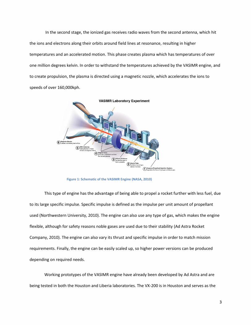
In the second stage, the ionized gas receives radio waves from the second antenna, which hit
the ions and electrons along their orbits around field lines at resonance, resulting in higher
temperatures and an accelerated motion. This phase creates plasma which has temperatures of over
one million degrees kelvin. In order to withstand the temperatures achieved by the VASIMR engine, and
to create propulsion, the plasma is directed using a magnetic nozzle, which accelerates the ions to
speeds of over 160,000kph.
This type of engine has the advantage of being able to propel a rocket further with less fuel, due
to its large specific impulse. Specific impulse is defined as the impulse per unit amount of propellant
used (Northwestern University, 2010). The engine can also use any type of gas, which makes the engine
flexible, although for safety reasons noble gases are used due to their stability (Ad Astra Rocket
Company, 2010). The engine can also vary its thrust and specific impulse in order to match mission
requirements. Finally, the engine can be easily scaled up, so higher power versions can be produced
depending on required needs.
Working prototypes of the VASIMR engine have already been developed by Ad Astra and are
being tested in both the Houston and Liberia laboratories. The VX-200 is in Houston and serves as the
Figure 1: Schematic of the VASIMR Engine (NASA, 2010)
4
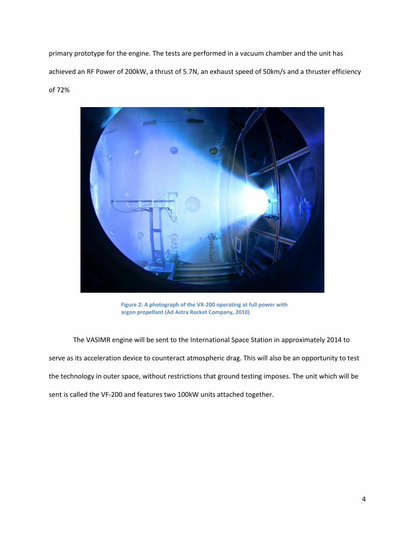
primary prototype for the engine. The tests are performed in a vacuum chamber and the unit has
achieved an RF Power of 200kW, a thrust of 5.7N, an exhaust speed of 50km/s and a thruster efficiency
of 72%
The VASIMR engine will be sent to the International Space Station in approximately 2014 to
serve as its acceleration device to counteract atmospheric drag. This will also be an opportunity to test
the technology in outer space, without restrictions that ground testing imposes. The unit which will be
sent is called the VF-200 and features two 100kW units attached together.
Figure 2: A photograph of the VX-200 operating at full power with argon propellant (Ad Astra Rocket Company, 2010)

5
2.2 Taurus II Launch Vehicle
The Taurus II Launch Vehicle is a cargo ship intended for resupply missions to the International
Space Station, and is manufactured and developed by Orbital (Orbital, 2010). This vehicle is intended to
provide low cost reliable access to the ISS for payloads weighing up to 5750kg, and uses identical
management approaches, engineering standards and other processes as Orbital’s already successful line
of small cargo commercial rockets, the Pegasus, Taurus and Minotaur launch vehicles (Orbital, 2010).
The launch system is designed to meet the National Aeronautics and Space Administration (NASA)
mission success standards. Orbital has for a long time been successful in the launch and operation of
space launch vehicles, suborbital launch vehicles, target vehicles and interceptor boost vehicles, and
shows a success rate of 100% in their Minotaur space launch vehicle program.
The Taurus II launch vehicle is intended to satisfy the need for a medium weight cargo vehicle to
resupply the ISS. To aid in its reliability and operation costs, the Taurus II makes use of several avionics
and components designed and flown on other Orbital spaceships. The rocket will initially be launched
from a Virginia Spaceport, but will have the capacity of being launched from any of the four major
commercial U.S. Spaceports (California, Florida, Alaska, Virginia). Orbital provides all necessary systems,
software, hardware and services to integrate, test and launch payloads in the Taurus II vehicle. The
technology will be available for use starting in 2011.
Figure 3: Taurus II Launch Vehicle (Orbital, 2010).

6
The Taurus II has the capacity to accommodate various payloads, depending on the needs of the
industry. The cargo bay features a 9872mm height from bottom to cone, with a diameter of 3936mm
and a total volume of 57.5m3 (Orbital, 2010) .The cargo space is enclosed by the payload fairing, which
consists of two halves which detach when the cargo needs to be deployed. The bottom of the cargo
space contains a payload interface which consists of a 1575mm diameter circular bolted payload
adapter. The payload is therefore only attached from the bottom. It is mated to the payload adapter
using custom designed separation systems, which orbital includes as a service to its customers. Figure 4
shows one of the mechanical interphases provided by Orbital. The electrical interphase is the dual sixty-
one pin Deutsch MIL-C-81703 bracket connectors, which provide communications to ground. Appendix
A.1 shows the pin distribution for this connector. Finally, the payload should be oriented in such a way
as to ensure that the Y and Z axes must lie within 51mm of the vehicles centerline and no more that
2000mm forward of the payload interphase. Mass accuracy calculations must be accurate to ±10kg,
while the moments of inertia shall lie at ±5% accuracy.
Figure 4: RUAG 1666 VS Payload Mechanical Interphase (Orbital, 2010).

7
The payload experiences certain conditions due to launch and operation, which need to be
taken into account when designing the cargo. Taurus II takes about 3130s from launch to payload
separation and throughout that time reaches a velocity of 7568m/s (Orbital, 2010). During launch, the
payload may experience accelerations reaching 6G’s in the axial direction and 0.2 lateral G’s. The
payload experiences vibrations of 1.2G’s in the 10-20Hz frequency range and axial direction. Before
launch, the vehicle experiences several thermal end humidity environments, and during the entire
launch operation temperature shall never exceed 93.3⁰C. Other relevant vibration, thermal and
acceleration properties are shown in Appendix A.1.

8
2.3 Design and Considerations for Space Structures
The design of space structures requires in depth knowledge of the space medium and understanding
of different phenomena which occur outside the Earth’s atmosphere. One must learn about the
temperature variations, vacuum, reduction in gravity, electromagnetic radiation and other concepts in
order to design functional and efficient space structures. Once these are taken into account, it is
necessary to explore materials, mechanisms and thermal control designs currently used in the space
industry. The combination of these concepts with basic structural, thermal and general design concepts
yield the best results for space vehicle design. Most of the information for this section is taken from the
Handbook of Space Technology, a guide published by Wiley containing fundamentals for space mission
and vehicle design (2009). The specific pages are indicated directly in the text.
2.3.1 Space Environment
Space structures are affected by the physical conditions found in space, which are completely
different to those found on Earth. The existence of high vacuum, solar radiation, ultraviolet X-rays and
the cold background of space are just a few of the considerations in designing any space structure or
vehicle (Library of Flight, 2009, pp. 34-35). The environment is characterized by the different mission
types, as the environmental conditions change through all of them.
Lower Earth Orbit (LEO)
Medium Earth Orbit (MEO)
Geostationary Orbit (GEO)
Polar Orbit
Highly Eccentric Orbit (HEO)
Orbits around the Lagrange Points
Interplanetary Space Trajectory

9
Planet Orbits and conditions for landing, ascent and ground operations
In the case of the VASIMR Extension Device, the specific conditions are those found in the low
Earth Orbit, as the unit will be attached to the International Space Station.
The first condition which should be studied is the electromagnetic radiation of outer space.
Radiation will approach the spacecraft from all directions, but the largest impact for spacecraft
operation is radiation from the sun (Library of Flight, 2009, p. 46). Energy impacting the spacecraft or
structure is transferred to thermal energy. Since outer space is a vacuum, thermal transfer can only exist
by either radiation or conduction which becomes very important when designing the thermal control
system for a space vehicle. Particularly challenging for the design of this system is the extreme
temperature gradients between surfaces facing the sun and those facing black space. These extreme
differences cause materials to experience thermal expansions and contractions leading to material
fatigue. Material selection should therefore be carefully monitored to account for the extreme
temperatures.
Electromagnetic radiation also causes a chemical influence on materials, as the densities of
short wave solar radiations are high enough to change their atomic structure. Electrons are separated
and left as free electrons. This is beneficial when considering the photoelectric effect, but unwanted for
other structures. One unwanted effect of this phenomenon is the electrostatic charging of some
surfaces of the space structure. The illuminated surfaces receive a positive charge and create a
differentiated charge throughout the structure. If the structure is oriented with the same side
illuminated all the time, then the structure might spontaneously discharge at certain times to reach
equilibrium, causing damage to equipment or surfaces.
Ultraviolet Radiation (UV) due to the electromagnetic radiation from the sun also causes several
effects (Library of Flight, 2009, p. 47). The electrical resistance of a material is slightly altered due to this

10
phenomenon. The materials also experience embrittlement, which is damage on the material as it
becomes brittle. Finally, on materials which are optically transparent, darkening might occur which leads
to lower illumination of optical instruments and solar cells, while also increasing their surface
temperature.
Next, it is important to explore the consequences of high vacuum on space design. At an altitude
of 500 km above the surface of the Earth, the barometric pressure is 10-7 Pa (Library of Flight, 2009, p.
49). High vacuum causes several physical processes which should be taken into account, mainly
outgassing or sublimation, change in material properties and cold welding.
Outgassing and sublimation are processes which occur with materials in high vacuum where any
absorbed gas and water escape from the materials. Sublimation describes the evaporation of atoms or
molecules as the ambient pressure falls below the steam pressure of the material. Outgassing refers to
the gasses or vapors escaping from the material due to the pressure difference. Both mechanisms create
mass loss and changes in surface properties. Some of the materials which tend to follow this process are
water, solvents, additives, uncured monomeric material and contaminants from the spacecraft before or
during the mission. The process might damage sensitive equipment such as thermal coatings, optical
instruments and high voltage devices, all of which are used on the VASIMR engine. Traditional lubricants
are also not suitable for outer space applications as they usually possess high specific steam pressure
values. Finally, the effect of gasses escaping the metallic parts might cause them to weld together in a
process called cold welding. This effect must be closely monitored especially for mechanical devices with
mobile parts.
2.3.2 Typical Design Process
Space structure design must begin with a comprehensive set of steps to properly reach a design
based on a set of constraints (Library of Flight, 2009, pp. 203-204). In order to achieve this, the

11
requirements of the device have to be defined, while also considering any constraints. These
considerations are known as the design drivers. These are mainly geometry based in the beginning,
where only the known use for the structure and the basic geometrical constraints are known. Figure 5
shows the typical structural design process.
Figure 5: Typical Design Process (Library of Flight, 2009)

12
2.3.3 Materials
In order to satisfy the mechanical and thermal requirements for the structures designed while still
obtaining the smallest mass possible, it is important to look into the field of material science to
understand the characteristics of different materials employed in the aerospace industry (Library of
Flight, 2009, p. 205).
Aluminum alloys are widely used as structural materials in the field of space structure construction,
due mostly to their characteristics. Aluminum alloys have high strength to weight ratio, making them
very useful in the aerospace business (Kutz, 2006, pp. 60-116). This means that the material has a
combination of relatively high strength with low density. It also exhibits excellent corrosion resistance
with high thermal and electrical conductivity. These last two properties are useful in space applications
as aluminum can be used for thermal and electrical conducting surfaces. Finally the material has
superior workability, owing to its ductility and is easily recyclable, though this last property is not
relevant for space applications. One of the largest problems with aluminum is that welding weakens the
material. This is bypassed by fabrication of one part structures out of large aluminum blocks and
mechanical joining procedures. Aerospace applications usually require a combination of mechanical
properties that has led to the development of alloys specifically for this area.
The use of titanium based alloys is also prevalent for high resistance applications, but is limited
by their high cost (Library of Flight, 2009, pp. 206-207). Beryllium alloys are also being developed since
they are extremely lightweight and have great mechanical properties, but their processing and handling
is difficult since they are highly toxic. The development of fiber composites, specifically carbon fiber, has
led the industry to extensively use said composites due to their low weight and high strength. These
composites also have the capacity to handle large temperature loads and can be molded to complicated
shapes. The problem with this specific technology is that the manufacturing process and materials are

13
expensive, curing times are usually long and the material is hard to work with. The use of fiber metal
composites is also prevalent in the aerospace industry and these materials use fiber composite sheets
combined with metals to mix mechanical advantages of fiber composites with the high temperature
resistance of metals. Finally, for high temperature applications ceramic matrix components,
carbon/carbon compounds and silicon carbide compounds are being developed.

14
2.3.4 Mechanisms
Mechanisms used in space applications need to be highly reliable and function properly without any
human assistance. These devices must be designed to withstand launch conditions and many years of
space exposure. Simple designs are also preferred to aid in the reliability of the mechanism.
Pyro mechanical separation mechanisms refer to devices which perform fast and reliable one time
separation using small explosive charges. The advantage of these devices is that they have high
reliability, and can be synchronized to exact timing. These mechanisms are mostly used for applications
where the separation has to occur at a specific time and has to be synchronized with other similar
mechanisms. One example of this mechanism is used to separate the Solid Rocket Boosters from the
main fuel tank in the Space Shuttle. Similar to these devices, non-explosive actuators are used when
short reaction time and synchrony is not critical. These mechanisms function by a chemical reaction
which is ignited and forces a piston or an equivalent device, resulting in the release of the attachment.
Figure 6 shows a wax motor which uses this principle.
Figure 6: Wax motor acting as a pin puller (Library of Flight, 2009, p. 225)

15
Spring mechanisms are widely used since they offer high reliability and simple manufacturing. The
purely mechanical design of the mechanism ensures that low weight is also achieved. Springs may also
serve as failsafe devices if a specific electrical motor does not work, as they can provide the rotational
force although they are limited to one time applications. Electric motors and drives are used in order to
generate the rotational and linear displacements necessary in certain mechanisms. These motors
require electrical input and are usually more complicated than mechanical devices but are able to
perform more complex tasks. They may be combined with spinning devices and flywheels which create
several rotational movements and when attached to linkages can create different displacements. Finally
there are bearings and similar mechanisms which are problematic as they may suffer from involuntary
cold welding. The use of space compatible dry or liquid lubricants is necessary to avoid this
phenomenon.
2.3.5 Structural Analysis and the use of Finite Element Models
Considering the complexity of space structures, their cost and the complicated conditions in
which they operate, mechanical behavior cannot be accurately described by analytical formulas alone
(Library of Flight, 2009, pp. 217-220). The use of computer models to thoroughly test these structures
has become the best option to ensure their reliability and safe operation during the design process. By
using these models, an engineer can create a design, test it and modify it without having to construct
the structure, therefore saving time and resources. The Finite Element Method is used to test these
structures; it uses a discrete mathematical model consisting of various finite elements connected
together at nodes, to represent the real structure. Finite Element Analysis method has three distinct
characteristics that account for its superiority over other methods (Ready, 2006). The first is that it
models a geometrically complex domain by subdividing it into sub domains, called finite elements. Over
each of the finite elements, the governing equations for the problem are used. The result is then
assembled together using predetermined inter-element relationships.

16
For this project, the Computer Aided Design (CAD) program used is Pro Engineer, which contains
a FEA module called Mechanica. All structural and thermal tests were performed using this module and
all graphs and result windows for tests either come from the software directly, or are derived from
information from the software. To analyze a model, a structured set of steps was followed in order to
obtain accurate results. These steps need to be completed in order and completion of each step is
necessary in order to move to the next one.
Figure 7: Pro Mechanica test design (Toogood, 2004)

17
2.4 Major Concepts used in Pro Mechanica
Pro Mechanica has the ability to calculate many different structural parameters after a test is
completed. Proper understanding of these concepts is vital in interpreting results and identifying
possible sources of error. Figure 8 shows a typical Pro Engineer result window with Von Mises Stress,
Displacement, Strain Energy and Von Mises convergence.
2.4.1 Stress
One of the most important concepts for the analysis of structures is stress. It can be divided into
two concepts, normal stress and shear stress (Hibbeler, 1997).
Normal stress is defined as the intensity of force, or force per unit area, acting normal to the
area.
Figure 8: Typical Pro Mechanica Result Window

18
Shear Stress is the intensity of force per unit area acting tangent to the area.
These concepts are described in Mechanica by the use of Von Mises Stress plots. When a
material is loaded in a system, a complex 3 dimensional set of stresses is developed (Logan, 1991).
These three principal stresses act on the X, Y and Z direction. Richard Von Mises found that in
certain cases even if none of the individual principal stresses exceed the yield stress, the material
might still yield due to the combination of stresses. He developed the Von Mises Criteria to create a
mathematical formula which would combine the results for the three stresses into an equivalent
stress, which is called the Von Mises Stress.
2.4.2 Displacement and Strain Energy
In order to explain the concept of deformation of a body, the concept of strain is used. When
any force is applied to a body, it will tend to change the shape and size of it, which is referred to as
deformation. Strain describes deformation by measuring changes in length.
Normal Strain refers to the elongation or contraction of a line segment (contained within the un-
deformed body) per unit length.
Shear Strain refers to the change in angle which occurs between two line segments (originated
in same point on the body and stretching along the perpendicular axes)

19
These concepts are shown in Pro Engineer as displacement graphics which show the total
displacement in three axes. The other concept that Pro Engineer shows is Strain Energy. As a
material is deformed by loading, it tends to store energy internally as strain energy, which is
measured in energy per unit volume. This specific measurement is used to describe two properties,
modulus of resilience and modulus of toughness.
Modulus of Resilience is the ability of an object to absorb energy without permanent damage to
the material.
Modulus of Toughness is the area under the stress strain diagram and it describes the strain
energy density before fracture. This describes the ability of a material to absorb energy in the
plastic range.
2.4.3 Convergence
Pro Engineer uses the convergence of P elements in order to calculate the results for testing
conditions. In order to verify the accuracy in the solution, the software monitors the convergence of the
results. Pro Engineer uses several passes to achieve convergence, which means that the software tests
the model various times, increasing the order of the polynomial by one. The difference in the results

20
from each pass is measured until a certain convergence is reached. In most tests for this project,
convergences of 5% were sufficient. Figure 9 shows the convergence results for a standard test.
As the results get closer and closer together, convergence for the test is reached. Convergence
can be measured with any of the results from the test including but not limited to Von Mises Stress,
Strain Energy, and Displacement.
Figure 9: Convergence results for a standard test

21
2.5 The International Space Station
The International Space Station (ISS) is an internationally developed research laboratory constructed
from 1998 to late 2011 (shuttlepresskit.com, 1999). It is the joint effort of sixteen nations, including the
United States, Russia, Canada, Japan, Brazil and eleven nations from the European Space Agency. The
station constitutes a pressurized volume of 837m3 with a mass of 375,727 kg, a length of 51m, a width of
109m and a height of 20m, and orbits Earth in 91 minutes. It is composed of sixteen pressurized
modules which house laboratories, docking compartments, airlocks, nodes and living quarters. The
station also holds non pressurized modules which hold many of the ISS’s external components and act
as structural modules. The VASIMR extension and engine will be attached to one of the non-pressurized
truss sections in the ISS and will provide the station with the necessary thrust to counteract atmospheric
drag. The main advantage of the ISS over traditional space ships is that long term experimentation can
occur, as the station is always manned. Figure 10 shows the various modules for the ISS.
Figure 10: ISS Configuration (NASA, 2007)

22
In order to standardize the design of components and additions for the ISS, a user guide was
drafted in 1997 and revised in 1998 which defined specific design requirements for power, thermal,
communications, environmental, human support and other systems (NASA, 1998). Any device which will
be attached to the ISS needs to follow this set of guidelines in order to ensure safe and reliable
operation of the ISS. This guide is the ISS Familiarization, code ISS FAM C 21109. Some of the concepts
which apply to the designs for the VASIMR extension device are discussed to ensure that the
requirements are met.
2.5.1 Electrical Power System
The ISS has two distinct electrical power systems, the ROS and USOS, which are responsible for
providing an un-interrupted power supply to the station (NASA, 1998, pp. 68-85). The station uses
photovoltaic panels to produce electricity which is transmitted to transformers which then regulate the
voltage level to those required for different applications. The power is also stored in sets of batteries so
it can be used when required. The power systems are divided into the Primary Power System, the
Secondary Power System and the support systems. The use of redundant components throughout the
architecture of the ISS electrical system is prevalent in order to avoid emergencies resulting in failure of
components.
The Primary Power System is regarded as the power channel, which is a group of hardware
components that are responsible for providing the primary power source. Some of the components in
this system include the solar arrays, batteries and other similar components. The Secondary Power
System serves to distribute and convert the primary power into secondary power, and may be used for
different applications. Some components included in this system are the DC to DC Conversion Units
(DDCU) that transforms primary power into secondary power. The power is then distributed to different
components. Finally the support systems include any other supporting functions which might be

23
incorporated into the architecture to maintain the USOS EPS. Components in this system include
thermal control units and grounding units.
2.5.2 Thermal Control System
Heat generated by experiments, machinery, and computers in the ISS must be removed using a
thermal control system (TCS), in order to maintain all of them within their required temperature ranges
(NASA, 1998, pp. 118-142). The TCS on the International Space Station is divided into two distinct types,
passive and active thermal control systems. Passive TCS consists of insulation, coating and heaters, and
these are characterized by few operational requirements and low maintenance. The purpose of this
system is to minimize temperature gradients and avoid heat escaping or entering. Examples of this
system are blankets and paint to avoid heating or cooling and electrically powered heaters used in
locations where it is impractical or impossible to satisfy both high and low temperature requirements.
Active TCS systems use mechanically pumped fluid to perform heat transfer, serving equipment with
higher heat loads and those where precise cooling is needed. The system consists of two loops, one
inside which transfers the heat of all components using water to a heat exchanger which transfers the
heat to an ammonia loop which transfers the heat to space. Water is used in the inside loop for safety
and simplicity reasons but would freeze if subjected to space temperatures, so ammonia transfers heat
from the station to space. The heat is irradiated into space using radiators which are made of aluminum
panels with stainless steel flow tubes. Stainless steel is used in the tubing due to the fact that ammonia
cooling systems are not compatible with copper tubing. The panels are hinged together and the tubes
are attached using flexible hoses.
24
2.6 Finite Element Analysis in Pro/Mechanica
Pro Engineer is a parametric 3D Computer Aided Design (CAD) software created by Parametric
Technology Corporation (PTC) in 1987 (PTC, 2010). The program runs of the Windows and UNIX
platforms and is able to do solid modeling, drafting, piping, cabling and finite element analysis (FEA)
using the Mechanica module. This module is sub divided into two major programs, structure and
thermal. Mechanica, more than FEA software, is a design tool since parametric studies and design
optimizations can be easily performed. The software is able to handle primarily linear problems and
does not react well to large deformations. In order to obtain correct results from the software, it is
essential to understand the design of the software and its limitations. A laboratory experiment was
designed to mimic testing conditions in the software and therefore compare results from theoretical,
laboratory and software tests.
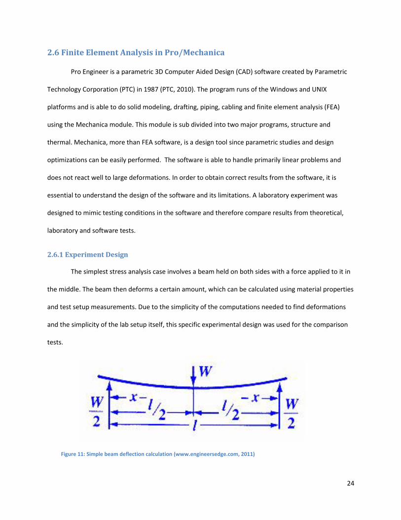
2.6.1 Experiment Design
The simplest stress analysis case involves a beam held on both sides with a force applied to it in
the middle. The beam then deforms a certain amount, which can be calculated using material properties
and test setup measurements. Due to the simplicity of the computations needed to find deformations
and the simplicity of the lab setup itself, this specific experimental design was used for the comparison
tests.
Figure 11: Simple beam deflection calculation (www.engineersedge.com, 2011)

25
2.6.2 Materials and Equipment
Nook ACTIONJAC Worm Gear Screw Jack
OMEGADYNE INC, Strain Gage Model: LCC101-3k
OMEGA Digital Readout
0-10mm Dial Micrometer, 1 Turn per millimeter
Fixed thickness Calibrated sheets
90 degree magnetic mount
Ad Astra Constructed Aluminum mounting plate
5 Al 6061 plates with measurements shown in Figure9
2.6.3 Experimental Setup
In order to approximate theoretical beam deformation equations, the experimental setup had
to resemble the theoretical setup as closely as possible. To achieve that goal, fixed thickness calibrated
sheets were used to act as the beam supports. Calibrated sheets are manufactured out of very strong
materials which would not deform under testing conditions and are of uniform geometry, making them
ideal for the test.
Figure 12: Beam Dimensions for the experimental setup

26
Al6061 beams were used in the experiment to take advantage of scrap materials left in the
shop. All plates chosen were in good condition, and did not show any signs of metal fatigue, welding or
deformations. Plates were cut into strips using band saws and continuous lubrication in order to avoid
thermal warping or weakening of the material, to the measurements specified in the materials section,.
Finally, the aluminum plates were marked with the test subject number and 2 lines, measuring 90mm
lengthwise. These lines would serve to position the calibrated sheets properly once the experiment was
assembled. The center of the plate was marked as well and a small galvanized steel plate was attached
using super glue to displace the dial micrometer leg as shown in Figure13.
Figure 13: Complete test setup with arrow pointing at galvanized strip

27
The strain gage apparatus was attached to the end of the screw jack, making sure to tightly
screw it in place to avoid damage of the screw threads. A screw with a flat end was attached to serve as
the force application point. The metal calibrated sheets were then attached and positioned using the
magnetic 90 degree setup apparatus. They were placed against an aluminum stop which was drilled into
the table. The aluminum sheets were positioned in front of the calibrated sheets and separated 90mm
between them by aligning the markings. The digital readout was recalibrated by zeroing it and the screw
jack was extended until the end of it barely held the aluminum sheet in place. Finally the Dial
Micrometer was attached to the table using its magnetic mount and its arm placed in contact with the
galvanized steel extension arm. The Dial was calibrated by turning it until it marked zero. The
experiments setup is now complete as shown in Figure14.
Figure 14: Complete experimental setup with digital readout marking 0kN and dial micrometer marking 0mm

28
2.6.4 Experimental Procedure
To start the experiment, the screw jack is cranked until the strain gage readout marks 1kN. The
deflection was recorded using the dial micrometer. The procedure would continue until the 5kN force
was applied, and would be performed 3 more times with three different aluminum sheets. Figure15
shows the deformations from 1kN to 4kN of one of the trials.
During the completion of the tests it was determined that a 5kN force created the largest
deformation possible without the material experiencing large plastic deformations. After the 5kN mark,
the beam experienced large deformations where the material had failed and started to slip from the
Figure 15: Test Results 1-4kN

29
calibrated sheets. Also the force could not be increased as the maximum marked by the digital readout
would stall at around 5.7kN where the material would deform without resisting, as shown in Figure16.
Figure 16: 5kN and maximum force (5.7kN) tests
2.6.5 Mathematical Calculations
In order to verify the results of the experiment, mathematical calculations for the idealized case
were performed. The result for displacement was taken using the equation for maximum deflection of a
beam with supports on both sides and a force applied in the middle.
Variable Meaning Units
E Modulus of Elasticity N/m^2
i Moment of Inertia m^4
W Load N
l Distance m

30
All of the variables in the equations were filled using the same values as those used for the
experiment. The beam had the same dimensions and the modulus of elasticity of Al 6061 was used. This
made the results correlate directly with those from both the software and the experiment.
2.6.6 Pro Engineer Model
The same experimental setup was created in Pro Engineer with some simplifications in order to
get the best results possible. The test was performed with the 5 loads described before and deflection
results were recorded. The beam element was mounted between two points placed 90mm apart. The
process was done using the beam element loading condition in Pro Mechanica, which idealizes a set of
interconnected points as a beam. Translation constraints were added on both sides, but the beam was
allowed to rotate to simulate the effect of the edge of the calibrated sheets acting on the aluminum
plate. A force was then applied at the middle point of the beam. Figure17 shows the test setup in Pro
Engineer.
Figure 17: Experimental setup showing constraints, loads and beam elements Figure 17: Experimental setup showing constraints, loads and beam elements
31
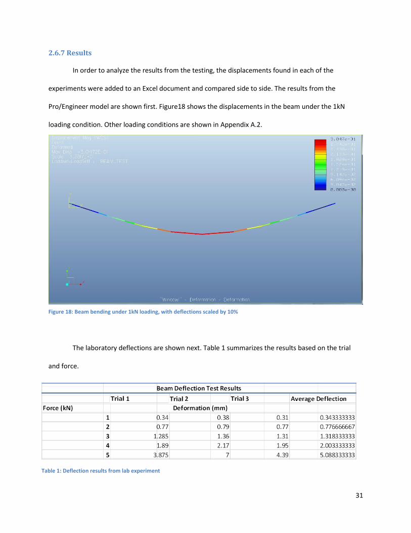
2.6.7 Results
In order to analyze the results from the testing, the displacements found in each of the
experiments were added to an Excel document and compared side to side. The results from the
Pro/Engineer model are shown first. Figure18 shows the displacements in the beam under the 1kN
loading condition. Other loading conditions are shown in Appendix A.2.
The laboratory deflections are shown next. Table 1 summarizes the results based on the trial
and force.
Table 1: Deflection results from lab experiment
Figure 18: Beam bending under 1kN loading, with deflections scaled by 10%

32
W Deflection (M) Deflection (mm)
1000 0.0003 0.2998
2000 0.0006 0.5996
3000 0.0009 0.8995
4000 0.0012 1.1993
5000 0.0015 1.4991
Beam Deflection Calculations
Force (kN) Experimental Deflection (mm) Mathematical Deflection (mm) Pro E Deflection (mm)
1 0.343 0.300 0.305
2 0.777 0.600 0.609
3 1.318 0.899 0.914
4 2.003 1.199 1.219
5 5.088 1.499 1.524
Beam Deflection Test Results
Finally the mathematical calculations for the simplified beam test were computed and are
summarized in Table 2. The exact mathematical process is documented in Appendix A.2.
The results of all the three experiments are shown side by side on Table 3.
The results show that Pro Engineer is very accurate before the material starts plastically
deforming. Its results are very close to theoretical mathematical calculations, due to the fact that it uses
linear equations to solve for the deflections. When entering into large plastic deformations both the
mathematical and Pro E results start deviating from experimental results.
This experiment provided the information necessary to better understand the limitations of the
software. The results show that as long as the object is not entering plastic deformation, Pro Engineer
gives accurate results. This is important and justifies the use of the software for the project since the
assembly must never enter the realm of plastic deformations.
Table 2: Deflections from mathematical calculations
Table 3: Combined experimental, mathematical and Pro E results

33
2.7 Extra Background Research
It is important to note that beyond the regular background research done for the project, many
additional skills were learned specifically for this project. While I had received two classes on Computer
Aided Design, one covering Solidworks and the other covering Pro Engineer, I did not have any
experience or knowledge of Finite Element Analysis and had to learn this before the project. In order to
do so, I had to study from various tutorial texts for Pro Mechanica in both thermal and structural tests.
These tutorial texts were purchased by me as they were not available in the library. Beyond this, I had to
learn the use of both cabling and piping programs. This was complicated as no tutorial books exist
covering this specific section of Pro Engineer, and online tutorials were expensive.
While the project covers the major design steps and processes for this assembly, it is necessary
to view the complete assembly in detail to fully understand the complexity of the structure. The final
design included over 200 parts, all designed for the purpose of the project. In terms of data, the entire
project generated over twenty gigabytes of data, mostly due to structural and thermal tests, which tend
to be space consuming. It is also important to note that the project only discusses the final design, but
two preliminary designs were also constructed, each containing tens and even hundreds of parts. This
product is the result of well over eight hundred hours of work in design, research, construction, writing
and miscellaneous tasks performed in the lab.

34
3. VASIMR ISS Extension Device
3.1 Introduction
In order to properly function when attached to the International Space Station, and to minimize
transportation costs, Ad Astra Rocket Company needs to design a structure which can extend to the
necessary position while still fitting inside the cargo space for a commercial rocket. The proposed
solution by the company’s engineers was to create a structure which has the ability to contract while
inside the cargo bay, and extend once it is attached to the ISS. The completed structure had to be able
to withstand the launch forces of the Taurus II commercial rocket, while still being as light as possible, in
order to decrease costs.
3.2 General Requirements
The structure was designed with the aid of the Design Requirement Document (DRD) used for
the Mockup Project (Ad Astra Rocket Company, 2010). This document is confidential and may not be
shared in this report but some of the basic guidelines are the following. Some guidelines have been
modified in order to hide specific details.
Structure shall be consistent with space flight hardware and shall include rough calculations for
6g accelerations.
Wires, housings and pipes shall have appearance of space flight hardware.
Fastening and joining systems shall be consistent with those used in space flight hardware.
The platform structure shall have the following components:
o A platform structure to which all other components are connected and which bolts to
the VX-200 engine bus and the deployment mechanism.
o Several enclosures representing different ORU’s.

35
o One folding radiator with articulation hardware.
o The platform structure shall have the primary dimensions and layout as given by the
project manager.
o The platform structure shall be created in Pro/Engineer.
The platform structure, deployment mechanisms and radiators shall fit within the fairing of the
Taurus II launch vehicle.
An interior corridor of the platform structure shall house the cabling and piping for the VASIMR
Bay.
The radiator shall have a surface area of at least 32m2.
The radiator when stowed shall fit within the main structure.
The ORU’s shall be designed following the DC to DC Converter Unit (DDCU) ORU.
Piping shall have the appearance of titanium.
The deployment mechanism shall be designed to minimize weight and use spaceflight
compatible hardware.
The deployment mechanism shall extend like a drawer in one degree of freedom.
Extra Vehicular Activity (EVA) handrails and worksite interfaces shall be appropriately mounted
to the structure to assist in EVA replacement of ORU’s, deployment of structure and other tasks
The list provided in the document deals with specifics for several components in the
deployment device, and those specifications will be listed in the design section for each of those
components later in the document.

36
3.3 Truss Structure Design
To attach the VASIMR Rocket Engine to the International Space Station, a sturdy and light
structure is needed which will position VASIMR correctly. The device must also function as a drawer to
minimize space taken by the frame during transportation, but still be able to handle all the loads
effectively. The design of this structure was tested for launch and operation loads, and its design was
optimized to reduce weight while providing the necessary structural rigidity.
3.3.1 Requirements
The requirements for the design of this structure came from Ad Astra Rocket Company’s DRD
for the Mockup Project (Ad Astra Rocket Company, 2010). General design requirements explained in
previous sections also needed to be followed. The document specified that the extension should
function as a drawer, while still fitting into the cargo space for the Taurus II Rocket Ship. The VASIMR
Bay has to be 6m away from the ISS attachment when fully extended and positioned. The bay has to also
tilt a specific amount when fully positioned. The drawers have to withstand the forces of both launch
and VASIMR operation, and be as light as possible to decrease transportation costs. Besides these
parameters set by the document, full liberty was given to investigate and use other space structures,
truss member orientations, materials and mechanisms.
3.3.2 Research, Motion Analysis and Changes in Original Design
In order to start with the design of the structure, the first step was to fully research space
structure design and the preliminary designs used for Ad Astra’s Mockup Project. Designs used for space
components are difficult to find and are usually confidential, so images were used to deduce structure
designs and materials. The International Space Station was investigated using this methodology and
provided clues on efficient space structure design, with the added advantage that NASA has many of
these images in high resolution.

37
3.3.3 Truss Orientation
Preliminary research determined that the design to be used is a square truss member expanding
in two drawers. In order to design this mechanism, simple truss design was studied and models were
tested to refine the initial idea. Pro/Mechanica was used to test different variations and compare results
in identical loading tests. The tests use constant cross sectioned members, in order to vary only the
beam orientation. The first design for the truss section was created by using the largest possible
structure which would fit inside the Taurus II cargo bay. In order to maximize this number, the box
should not exceed 3936mm in any dimension (Orbital, 2010). This number was rounded to 4000mm for
the calculation and resulted in 2830mm for the length of each side of the box, which was decreased to
2400mm so cabling and other components would properly fit, and to make the payload mounting
operation simpler. Figure 19 shows the cargo bay dimensions as well as the maximum side length
calculations.
Figure 19: Taurus II cargo space (Orbital, 2010), and calculations for sides of the box.
38
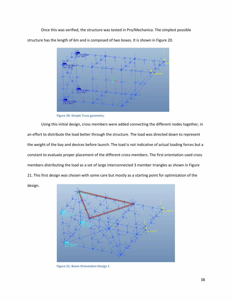
Once this was verified, the structure was tested in Pro/Mechanica. The simplest possible
structure has the length of 6m and is composed of two boxes. It is shown in Figure 20.
Using this initial design, cross members were added connecting the different nodes together, in
an effort to distribute the load better through the structure. The load was directed down to represent
the weight of the bay and devices before launch. The load is not indicative of actual loading forces but a
constant to evaluate proper placement of the different cross-members. The first orientation used cross
members distributing the load as a set of large interconnected 3 member triangles as shown in Figure
21. This first design was chosen with some care but mostly as a starting point for optimization of the
design.
Figure 20: Simple Truss geometry.
Figure 21: Beam Orientation Design 1

39
Max Disp 4.536
Disp in X 0.841
Disp in Y -4.454
Disp in Z -0.428
Displacement Results (mm)
The initial orientation from design one gave some interesting results which can be used to
understand where the structure is efficient, and where it needs work. Once the test was completed,
Pro/Mechanica results and visualizations were created. The Von Mises stress plot results show that
there was heavier loading in only two out of the 4 large triangles created and that most of the members
in the assembly were not loaded significantly. This means that most of the members in the assembly are
not supporting a significant load, making their positioning inefficient. Displacement results are shown in
Table 4.
Table 4: Displacement Results Test 1
Figure 22: Von Mises Stress results for design 1

40
Design 1 Design 2 Design 3 Design 4 Design 5
Max Displacement (mm) 4.536 4.563 4.514 4.355 4.331
Max Displacement X 0.841 -0.846 -0.851 0.837 0.839
Max Displacement Y -4.454 -4.484 -4.464 -4.233 -4.248
Max Displacement Z -0.428 -0.669 0.412 -0.595 0.410
Max Stress von Mises (Mpa) 21.846 21.487 21.749 21.754 22.046
Strain Energy 108622 111586 111515 105765 105669
Results for 5 Designs
The design was further optimized by re arranging the elements to where the structure was
efficiently used and the displacement was minimized. This process took five different designs which are
documented in Appendix A.3. The final design uses lateral beams which carry the load from the point of
application to the fixed end. The beams crossing on the top and bottom serve to carry the load and
provide the lateral structural rigidity necessary for the structure. Figure 23 shows the Von Mises stress
results for the final design along with Table 5 which shows the displacement, strain energy and Von
Mises stress results for all of the assemblies. It is clear that design five has the best load distribution
properties and deflects the least while still providing acceptable stress values.
Figure 23: Von Mises stress visualization of final design
Table 5: Results for 5 Designs

41
Filled Hollow I-Beam
Max Disp (mm) 0.3624 1.0065 1.0065
Max Disp X -0.0069 0.0063 0.0084
Max Disp Y -0.0130 -0.0062 0.0064
Max Disp Z 0.3621 1.0064 1.0064
Max Stress VM (Mpa) 10.6228 42.4076 44.4207
Weight (kg) 67.65 24.39 24.39
Beam Cross Section Test Results
3.3.4 Truss Cross Section Analysis
After the analysis of the orientation of the trusses, another optimization exercise can be
performed to decrease the weight and make the structure more efficient. The cross section of each of
the beams can be analyzed in fixed loading conditions to view the way each cross section reacts. Three
different cross sections were used in the test, a solid beam, a hollow beam and an I-beam. All of the
beams were weighed in order to find the best weight to strength relationship. All beams were tested in
the same conditions, with fixed load acting axially in tension. Another test was done on each of the
beams with compression loading in order to identify all possible loading conditions in the structure. All
beams were simulated to be made of Al 6061 so that weight comparison could be relevant, and because
it is a material commonly used for this application. Table 6 shows the deflection, VM Stress and weight
of each of the beams, and beam stress results are shown in Appendix A.3.
The results in this section show that the filled beam weighs three times as much as the hollow
and I beam, and when comparing the results for maximum displacement and stress, both the I-Beam
and hollow beam perform similarly. In the end, the I-Beam was chosen as the default beam due to the
advantageous properties it has dealing with buckling, which was not modeled by the software. Another
important consideration which was taken into account is the attachment of said beams to the structure.
While the hollow beam provides a flat area to make the necessary attachment, the I-beam has more
Table 6: Beam Cross Section Results

42
material in its cross section at the point of attachment, leading to better performance when mechanical
fasteners are used.
3.3.5 Material Selection and Optimization
One final design optimization process deals with the materials which should be used for the
construction of the truss structure. In order to perform this analysis, the CES Edupack software was
used. It contains a database filled with many materials and their properties as well as the shaping
processes which can be performed on the materials and a list of manufacturers. The software works by
performing a series of tests in stages, where different parameters can be specified and materials which
do not comply with those parameters are excluded. After a series of stages is completed, a small list of
possible materials is available and the engineer can then decide which one to use. Parameters which can
be compared in the software include mechanical properties, like young’s modulus, general properties
like price and density, thermal properties, optical properties and many others. Using this tool, the
beams can be optimized to be as strong and lightweight as possible, while adhering to price and
processing constraints.
Before running any stages, there are 2954 materials available. In order to optimize the structure,
the first step is to get rid of materials not suitable for space applications. Materials excluded here are
those which are porous, natural materials, ceramics, as they are brittle, and other materials with similar
parameters. Once this stage is complete, the list is reduced to 2557 materials. Before the next step, a
standard material will be specified. This material is going to act as a baseline, where any material must
perform equally well or better than it, so that it can be considered. The material chosen is Al 6061 T6,
which is commonly used for truss space structures, as any material which should be considered has to
have at least the same mechanical properties.

43
The next stage consists of eliminating any material which has lower yield strength than the
standard material. This would result in a material which is stronger, and as such, less material could be
used in the assembly, leading to potential savings in weight. The material field is lowered from 2557 to
1411. Any material with a stiffness to weight ratio lower than the standard material was eliminated. A
graph with young’s modulus over density is created and all materials which lie below Al6061 T6 are
eliminated. The field again reduces from 1411 to 843. Figure 24 shows the results of these first stages,
the gray lines represent materials which have not passed the test. Al 6061 T6 is marked.
The material field has thinned out considerably and in order to continue with this process the
next stage will test the cost of the materials. CES Edupack lists many different materials, some of which
have great mechanical properties, but a lot of them are exotic materials which are very expensive and
time consuming to form and manufacture. The cost of an aluminum block of 1m3 in volume is around
$5,000. Materials with values of over $20,000 will be eliminated. The graph uses the price per mass
times the density which results in a price per volume. The list of materials thins out from 843 to 433.
Figure 25 shows the resulting graph with the materials that have passed all the stages.
Figure 24: Young’s Modulus/Density with all materials
Figure 25: Density* Price graph
44
Analyzing the remaining results it is clear that the only remaining materials are aluminum
variations, and steels. This is expected as very few materials have the low cost of aluminum while
retaining its mechanical characteristics. One possible alternative is the use of Ultra High Strength Steels
(UHSS) for the assembly. These materials are very strong when compared to aluminum and are also
cheap. These materials were developed by the steel industry for the automotive industry, in order to
avoid aluminum to become widely used. They are the standard in car technology due to their high
strength, which means less of the material can be used. Another advantage that these materials have is
the fact that they can be welded without having any adverse mechanical effects like those that happen
to aluminum. Finally, forming processes and machinery for these materials is widely available since it is
used in many applications, which might lower the production costs for the parts.

45
3.4 VASIMR Bay Design
The VASIMR extension device serves the purpose of positioning the VASIMR engine at a specific
position and angle. This section focuses on the design of the structure where the VASIMR engines will be
mounted, which also houses the orbital replacement units and cabling and tubing for the engine. The
bay was designed taking into consideration an initial iteration given by Ad Astra in their Design Review
Document. Figure 26 shows this design. The design requires two sides where ORU’s would be attached,
two holes in the top where the two VASIMR engines would go and a space in between the structure
where the cabling and piping for the units would go. The concept shown does not have any skeletal
structure and is only composed of the box walls.
3.4.1 Requirements
The VASIMR bay structure had to first comply with the general requirements set by the DRD
document discussed in the beginning of the design chapter. The design has to resemble the original bay
design shown in the figure above, but only in its function, not its final design. It had to also comply with
the following requirements:
The unit must fit inside the truss drawer structure designed in section 3.3.
Figure 26: Original Bay Design
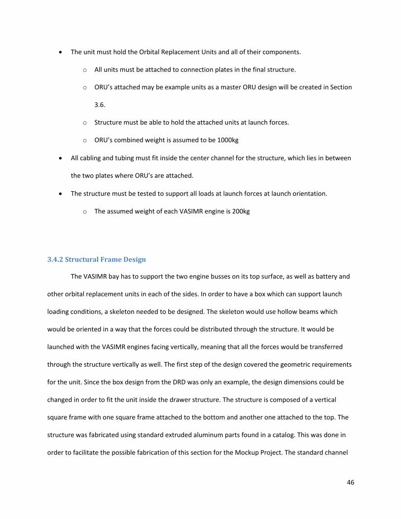
46
The unit must hold the Orbital Replacement Units and all of their components.
o All units must be attached to connection plates in the final structure.
o ORU’s attached may be example units as a master ORU design will be created in Section
3.6.
o Structure must be able to hold the attached units at launch forces.
o ORU’s combined weight is assumed to be 1000kg
All cabling and tubing must fit inside the center channel for the structure, which lies in between
the two plates where ORU’s are attached.
The structure must be tested to support all loads at launch forces at launch orientation.
o The assumed weight of each VASIMR engine is 200kg
3.4.2 Structural Frame Design
The VASIMR bay has to support the two engine busses on its top surface, as well as battery and
other orbital replacement units in each of the sides. In order to have a box which can support launch
loading conditions, a skeleton needed to be designed. The skeleton would use hollow beams which
would be oriented in a way that the forces could be distributed through the structure. It would be
launched with the VASIMR engines facing vertically, meaning that all the forces would be transferred
through the structure vertically as well. The first step of the design covered the geometric requirements
for the unit. Since the box design from the DRD was only an example, the design dimensions could be
changed in order to fit the unit inside the drawer structure. The structure is composed of a vertical
square frame with one square frame attached to the bottom and another one attached to the top. The
structure was fabricated using standard extruded aluminum parts found in a catalog. This was done in
order to facilitate the possible fabrication of this section for the Mockup Project. The standard channel

47
used had the dimensions shown below in Figure 27. This channel provided the necessary space between
both attachment walls for cabling as well. The size of the structure is also determined by the ORU sizes,
which were specified in the DRD but are confidential.
Once the initial design was completed, reinforcements for the structure were added in order to
support the loads for the ORU’s and both VASIMR engines. Beams were extended from the top of the
strucure to the central beam to provide support for the VASIMR engines. An X structure was added to
the central wall in order to serve as a holding point for ORU’s and to provide the box with lateral rigidity.
This section was reinforced with horizontal bars to serve as additional mounting points for ORU units. In
the top of the bay, a rounded mounting point was added to support the VASIMR rockets, resembling
that same structure shown before in the preliminary bay design drawing. The resulting structure is the
backbone of the entire VASIMR bay design, and all of the components, ORU’s , cabling and piping are
mounted around the design of this structure.
A structural test was perfomred on the unit as well in order to ensure that it could support the
necessary forces from launch and weight from the VASIMR engines and ORU’s. The test was performed
using the beam simplification for structural design in order to simplify the calculations for the computer.
Figure 27: Bay preliminary dimensions, and channel dimensions
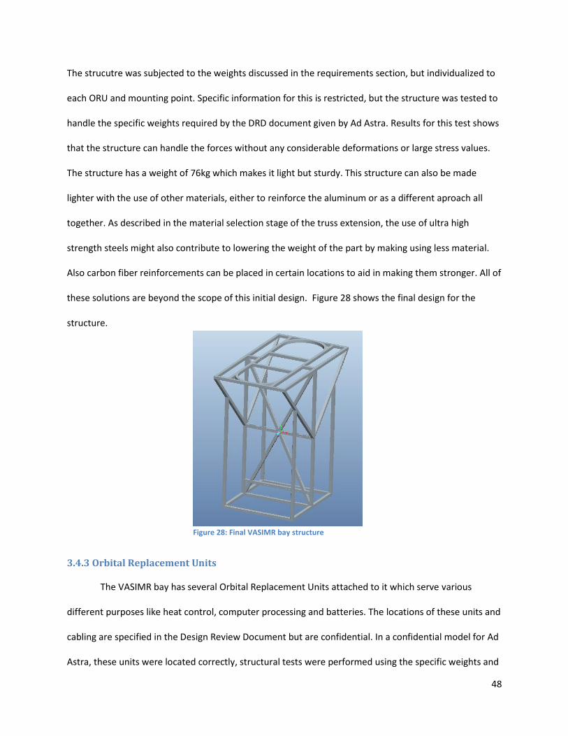
48
The strucutre was subjected to the weights discussed in the requirements section, but individualized to
each ORU and mounting point. Specific information for this is restricted, but the structure was tested to
handle the specific weights required by the DRD document given by Ad Astra. Results for this test shows
that the structure can handle the forces without any considerable deformations or large stress values.
The structure has a weight of 76kg which makes it light but sturdy. This structure can also be made
lighter with the use of other materials, either to reinforce the aluminum or as a different aproach all
together. As described in the material selection stage of the truss extension, the use of ultra high
strength steels might also contribute to lowering the weight of the part by making using less material.
Also carbon fiber reinforcements can be placed in certain locations to aid in making them stronger. All of
these solutions are beyond the scope of this initial design. Figure 28 shows the final design for the
structure.
3.4.3 Orbital Replacement Units
The VASIMR bay has several Orbital Replacement Units attached to it which serve various
different purposes like heat control, computer processing and batteries. The locations of these units and
cabling are specified in the Design Review Document but are confidential. In a confidential model for Ad
Astra, these units were located correctly, structural tests were performed using the specific weights and
Figure 28: Final VASIMR bay structure

49
dimensions but is not included in the project. Cable thicknesses were also calculated using the voltages
and currents that these cables were to transfer but these again are confidential. For the VASIMR bay
designed for this section, ORU units are simulated and not specifically assigned to any task. The cabling
is also simulated in order to show possible arrangements and most of all serve as an exercise in cabling
and piping design. The units were designed to resemble real units and have some of the requirements
for real ORU design, but only serve as an example. A real ORU is designed and discussed in detail in
section 3.6.
3.4.4 VASIMR Interphase Design
In order to attach both VASIMR engines to the bay, an interphase needed to be designed. The
DRD required that the interphase be round and have a series of screws to attach both structures
together. The design had to also leave space to connect all cabling and piping which needed to go to the
VASIMR engines. The frame was designed to fit in the round space at the top of the frame, and had to
be sturdy enough to transfer all launch forces to the frame without failing. A frame was created from
aluminum and has 80 attachment holes for screws with a 25mm diameter. The frame has two lips, to
serve as the screwing points and has various holes to allow for piping and cabling. Figure 29 shows the
final interphase design.
Figure 29: VASIMR interphase final design

50
3.4.5 Covers, Cabling and Other Items
The VASIMR bay requires the addition of covers to protect the devices housed in it and for visual
and protection reasons. The entire structure was covered on the outside with matte white panels,
following NASA regulations. These serve to protect the structure and components from launch forces,
space debris and space manipulation. The bay was also fully cabled using simulated connections. Finally,
a representative VASIMR engine was mounted on top of the bay, to serve as a visual representation. The
final design also has a human analog which puts into perspective the actual size of the structure. Figure
30 shows a series of pictures with the finalized design.
Figure 30: Assorted VASIMR bay pictures

51
3.5 Radiator Design
A radiator serves the purpose of extracting heat from a source and releasing it to the
environment. To do so the radiator may use, radiation, convection or conduction. In space applications,
designs of radiators differ greatly from those used on Earth. This is due to the fact that there is no
medium in contact with the radiator to provide conduction or convection and all heat must be released
through radiation. Also temperature changes in space occur quickly and variations are large, so care
must be taken when choosing its materials and design. The structure must be equipped to handle the
extreme forces present during launch. Finally, since surface area needs to be large, and space is limited
in the spaceships cargo bay, the radiator must be able to fold for transport and extend for use. In order
to design a radiator mechanism and system for the VASIMR rocket engine, all of these considerations
must be taken into account.
3.5.1 Requirements
The DRD for the mockup project provided by Ad Astra Rocket Company was used to determine
the requirements of the project. Thermal calculations had already been done and the information
provided by the document was that the surface area of the radiator must be equal to or slightly exceed
32m2, where both sides of the radiator count towards the surface area. As with the rest of the assembly,
the radiator had to fit inside the Taurus II rocket’s cargo bay, and it must be folded during launch and
extended during assembly. Besides the general requirements mentioned, the document gave liberty in
the actual design of the mechanism, extension method and materials.
Additional design limitations had to be achieved for the radiator to fit with the rest of the
assembly and as such, the radiator could not be more than 1800mm in width and 2200mm in height.
The final thickness of the radiator could also not exceed 500mm. These parameters had to include the

52
housing structure as it all had to be attached to the VASIMR Bay assembly without it colliding with the
modules in which it is housed. The space available for the radiator can be visualized in Figure 31.
Figure 31: VASIMR Extension Assembly with space left for radiator mechanism
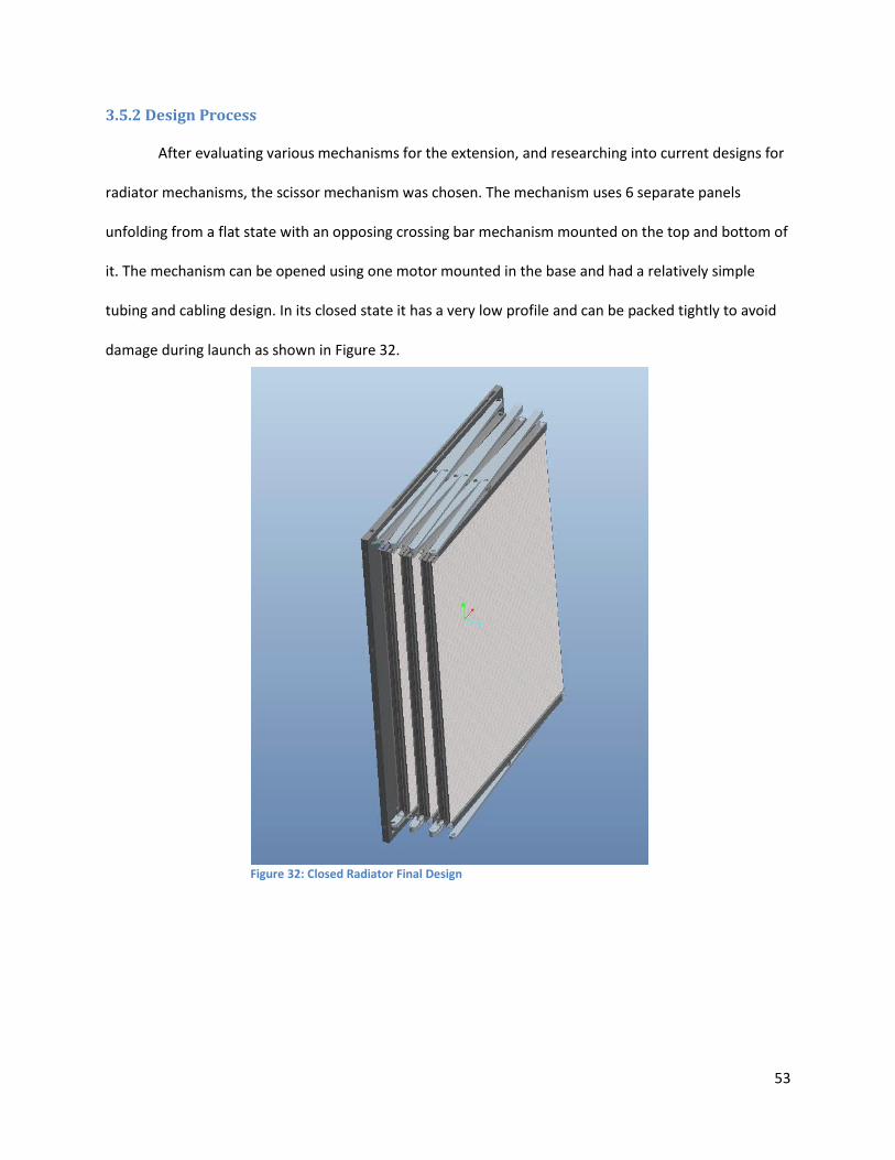
53
3.5.2 Design Process
After evaluating various mechanisms for the extension, and researching into current designs for
radiator mechanisms, the scissor mechanism was chosen. The mechanism uses 6 separate panels
unfolding from a flat state with an opposing crossing bar mechanism mounted on the top and bottom of
it. The mechanism can be opened using one motor mounted in the base and had a relatively simple
tubing and cabling design. In its closed state it has a very low profile and can be packed tightly to avoid
damage during launch as shown in Figure 32.
Figure 32: Closed Radiator Final Design
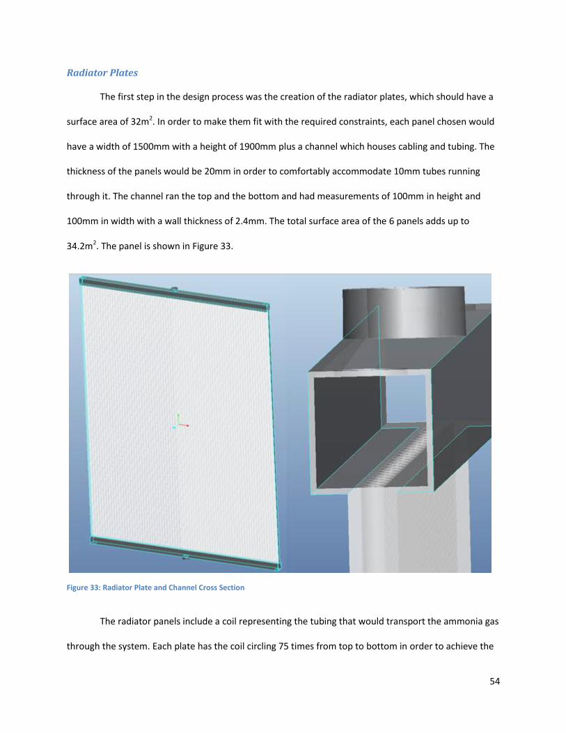
54
Radiator Plates
The first step in the design process was the creation of the radiator plates, which should have a
surface area of 32m2. In order to make them fit with the required constraints, each panel chosen would
have a width of 1500mm with a height of 1900mm plus a channel which houses cabling and tubing. The
thickness of the panels would be 20mm in order to comfortably accommodate 10mm tubes running
through it. The channel ran the top and the bottom and had measurements of 100mm in height and
100mm in width with a wall thickness of 2.4mm. The total surface area of the 6 panels adds up to
34.2m2. The panel is shown in Figure 33.
The radiator panels include a coil representing the tubing that would transport the ammonia gas
through the system. Each plate has the coil circling 75 times from top to bottom in order to achieve the
Figure 33: Radiator Plate and Channel Cross Section

55
best heat transfer while still allowing for the tube’s bending radius. The tubing used for ammonia
thermal systems needs to be either aluminum or stainless steel, which needs to be taken into account
for future applications. It must be noted that thermal requirements for the radiator were not released
so the design is a representation of the system, but not specifically designed with any parameters in
mind besides the surface area. The channel houses the ends of the coils as well as cabling for sensors
and other devices. Figure 34 shows the final panels with the tubing included.
Scissor Mechanism
The use of the scissor mechanism in the radiator has many benefits in terms of construction and
operation. As stated before, the system can extend using only one motor mounted on the base. The
bars serve to transfer the movement and also direct the plates in the direction that is needed.
Traditional scissor mechanisms use two arms attached to each other at the middle, and the ends of each
of these attaches to another set of arms. In the radiator design, the panels serve as one of the arms
explained, and the mechanism has attachments on both the top and the bottom. This makes the design
Figure 34: Final Panel Construction with tubing included

56
sturdier as forces applied are balanced on both the top and the bottom. Figure 35 shows the extended
mechanism from a top view.
Each of the panels was fitted with an attachment point in the middle of it which would serve as
the mounting point for the scissor mechanism. The extension arms were 1550mm long and 30mm thick.
The extra 50mm added to the arms exists so that the arms never extend past parallel with the panels. If
the arms had the same length as the panels they would extend completely straight when actuated,
reaching a toggle point. Fig 36 below shows the panels extended completely straight while the arms still
being able to retract the radiator if necessary.
Figure 36: Fully extended radiator.
Figure 35: Radiator Scissor Mechanism

57
Radiator Housing
The last part of the radiator which had to be designed was the radiator housing. This not only
serves as an attachment to the VASIMR Bay, but also actuates the radiator arm to begin the extension
movement. The housing had to be closed in the back in order to protect the extension mechanism once
the radiator is fully extended.
The housing was created using a square aluminum frame with a slider mechanism and a fixed
pivot point. The radiator’s scissor arms would then attach to the fixed pivot point and the panel would
displace using the slider to extend the radiator. The frame had to be larger than the radiator to house all
of its structure when closed, but small enough to fit under the VASIMR Bay without colliding with the
modules. The housing structure with the radiator both extended and stored is shown in Figure 37.
Figure 37: Radiator Housing in closed and extended positions.

58
3.6 Orbital Replacement Unit Design
Orbital Replacement Units (ORU) are used in space applications in order to simplify repair
operations on a space vehicle or structure. The units are designed to house sets of components which
can be replaced by astronauts when they malfunction. These units house bundles of equipment in order
to simplify repair operations as much as possible. ORU’s serve three distinct purposes; they can be
replacement units for malfunctioning equipment, update units which might improve the performance of
the instrument or units which change the functionality of the equipment all together. The units must be
designed with certain considerations, as they have to be handled by astronauts using a full body suit and
in zero gravity conditions. Figure 38 shows an astronaut performing maintenance on the ISS, it
important to note the design of the components the astronaut is handling as this is the best method of
understanding ORU design since these are usually confidential.
Figure 38: Astronaut performing maintenance on the ISS (NASA, 2010)
59
Ad Astra Rocket Company will utilize these units in order to create equipment bundles for future
maintenance, and need information on the units as well as preliminary designs. The units included in the
extension device serve only as simplifications of the real units and have not been engineered to follow
most of the requirements, so a single model unit was created to serve as an example for future designs.
The unit was created using most of the requirements set by the mockup projects DRD, and was designed
with simplicity and ease of use in mind.
3.6.1 Requirements
The Mockup Projects DRD served as a starting point for the requirements of this unit, but
research was also done to better understand an astronaut’s mobility limitations as well as current
designs for these units. Information on the units is scarce since most of them lie under restricted
documentation or are patented. The specific requirements that relate to the design of the units are
listed below.
The units must not have sharp corners or protrusions which might damage an astronaut’s space
suit.
The units must have a guiding mechanism which ensures that thermal and electrical connections
are not damaged.
Electrical and thermal connections must connect automatically as the unit is locked in place.
All handles should accommodate an astronaut’s glove comfortably.
The example unit must resemble the size of a large ORU. (800mm high x 300mm thick x
1000mm deep)

60
3.6.2 ORU Design
The ORU designed is 1100mm deep, 300mm wide and 800mm tall. The unit contains a back
plate with the thermal and electrical connections, a locking mechanism, internal components and a box
protecting it all. The unit also has a handle to ease with its control and aligning wheels which serve to
place the unit precisely in the right place to avoid damage. The other two handles in the front are part of
the locking mechanism and turn 90 degrees in order to lock or unlock the mechanism in place. Figure 39
shows the complete unit locked in place inside the enclosure.
The back plate of the ORU serves as both a thermal plate, and housing for the electrical
connections. The design followed an image provided in Ad Astra’s DRD document. The image shows the
back plate of the DC to DC converter ORU unit used in the ISS, as shown in Appendix A.4. The picture
shows that the thermal conduction plate is composed of an array of fins which interlock with an
opposite array when attached. The image also shows the electrical connections for the ORU are housed
in the outside.
Figure 39: ORU housed inside the enclosure

61
Considering that the unit should have the simplest design, the electrical connections were
removed from the side and placed in a cavity in the thermal plate. This not only benefits the simplicity of
the assembly but also provides protection to the connectors, as they are surrounded by the thermal
plate. The connector plate would also be protected from damage by the fins which if not aligned
properly, would not allow the connectors to touch. On the other side of the plate, a connector was
added to provide an input from all the devices in the ORU. Aluminum was chosen as a material for the
back plate as it transfers heat well and is lighter than other materials. Figure 40 shows the final back
plate design and a close up of the electrical connections.
In order to provide a more realistic design of the ORU, internal components were added to show
examples of how the unit might look like. The unit was given 3 internal compartments which can house
anything from batteries to computers. They were connected to the back plate using a set of sockets and
cables. The harnesses and cables were all created and routed using Pro/Engineer’s Cabling application.
Figure 40: ORU Back Plate design, Close up of electrical and thermal connections

62
The unit also received a thermal conduction plate where copper tubes were used to transfer the heat
from the devices to the back plate. The insides and cabling is shown in Figure 41.
The use of copper is limited as it is heavier than aluminum so only the thermal tubes were made
out of copper, in order to provide a conducting path to the back plate. The thermal conduction plate is
attached to the unit using standard screws. In order to do the cabling, sockets and plugs were designed
to transfer information and electricity from the connection plate to the compartments housed inside the
ORU. These cables are only examples and the assembly might be modified for different parameters,
thicker cables or different socket types, but that was beyond the scope of the design. Figure 42 shows a
detailed view of the cabling and thermal plate design.
Figure 42: Detailed view of cabling and copper tubing
Figure 41: Inside compartments of ORU unit, right side shows lateral view with cabling and copper tubes

63
The design also required a mechanism which would lock the device in place, hold it in and
connect the thermal and electrical devices with its movement. The mechanism had to be simple in order
to both make its operation easy and ensure that it does not break down. The use of a lever with a spring
mechanism and a key interphase was used to increase reliability and decrease production costs and
weight.
The design consists of shaft, machined hollow but left with centering flanges throughout its
length. At the bottom end of the tube is an endplate which serves to hold the spring in place. Inside the
tube runs a solid shaft with a larger diameter protrusion at 24 mm from the bottom which holds the
other end of the spring in place. The top end of the shaft is attached to a handle and the bottom end is
attached to the key device and an aligning device. The shaft can rotate as well as move parallel to its axis
for 24 mm in order to actuate the sprint mechanism. Figure 43 shows the shaft end with the endplate,
spring and key attachment and the complete shaft with the handle.
Figure 43: Full locking mechanism and close up of shaft, tube, key and spring devices in mechanism.

64
As the astronaut finishes inserting the ORU, and the key is aligned with the hole, he pushes the
handle in, actuating the spring, and rotates the handle 90 degrees, to the locked position. Once he lets
go, the spring will expand, locking the ORU in place. Figure 44 shows the mechanism with the guiding
cover and the mechanism with its key inserted into the key hole.
The unit was completed by adding a cover which serves to protect the components and acts as a
mounting point for the guiding system and astronaut rails. The system is guided into the enclosure using
a series of wheels and rails. This ensures that the connections are properly aligned.
Figure 44: Mechanism with guiding cover and the mechanism with its key inserted into the key hole

65
3.7 Payload Fairing Design
One additional design that Ad Astra wanted for the model is the fairing which connects the
VASIMR extension device to the Taurus II rocket. As covered before, Orbital provides standard fairings
and will aid in the development of the fairing for the cargo, but Ad Astra desired an initial design which
they could work from. This structure had to be designed to comply with the mating conditions that exist
in the Taurus II cargo bay, and support extreme forces form the assembly.
3.7.1 Design Requirements
The fairing designed for the project had to attach to the Taurus II standard payload mechanical
interphase shown in Figure 45.
The structure must attach to the Taurus II with screws and have various mounting points to the
extension structure to ensure safe transportation
The structure must be able to support 7,500 kg at maximum launch forces (6G)
Figure 45: Standard mechanical interphase Taurus II Rocket (Orbital, 2010)

66
3.7.2 Design and Testing
The design for this part needed to be as simple and reliable as possible. Since the interphase
which attaches to the Taurus II rocket has a diameter of 1575mm, the lower portion of the device is a
round plate with this diameter, where the interphase will be attached with 121 screws. From this
surface, a series of four legs branches from the center at an angle in order to attach to the four edges of
the box. I-Beams are used and plates are attached to their ends where the pyro-screws would attach.
The four legs are connected together in an X. For testing, all four legs are loaded with a total of 450,000
N, which is the equivalent of 7,500kg at 6G’s.The calculation for 7500kg is almost 1.6 times the expected
weight for the assembly in order to give the test a high security factor. The attachment is made out of
aluminum. Figure 46 shows the first design.
Figure 46: First Payload Fairing Design
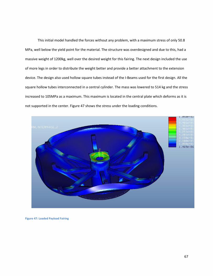
67
This initial model handled the forces without any problem, with a maximum stress of only 50.8
MPa, well below the yield point for the material. The structure was overdesigned and due to this, had a
massive weight of 1200kg, well over the desired weight for this fairing. The next design included the use
of more legs in order to distribute the weight better and provide a better attachment to the extension
device. The design also used hollow square tubes instead of the I-Beams used for the first design. All the
square hollow tubes interconnected in a central cylinder. The mass was lowered to 514 kg and the stress
increased to 105MPa as a maximum. This maximum is located in the central plate which deforms as it is
not supported in the center. Figure 47 shows the stress under the loading conditions.
Figure 47: Loaded Payload Fairing

68
The design and testing was optimized by increasing the diameter of the hole in the central plate, in
order to avoid stress concentrations on the plate, as the central tube carries most of the weight. Also
the square hollow tubes wall thickness was decreased from 10mm to 5mm. Finally the cover sheet
which surrounds the attachment was removed, as it only serves as a cover and is not supposed to carry
any load. The resulting device has a mass of 250kg, and still handles the weights without exceeding any
yield parameters. Figure 48 shows various views of the final fairing design and tests which are all shown
with 10% magnification to allow easy viewing.
Figure 48: Various Views of the payload fairing
69
4. Thermal Data Migration from Thermal Desktop to Pro Mechanica
Ad Astra uses a program called Thermal Desktop to analyze thermal tests due to the fact that
Pro Mechanica lacks the features necessary for these simulations in vacuum chamber environments.
They desire a simple method of transferring the thermal data and moving it into Pro Mechanica for
further structural tests. With this information, they could complete the picture and test parts with both
temperature and mechanical loads applied. Using Pro Engineer’s ability to read FNF files, and
information acquired from Thermal Desktop, a comprehensive guide was created with all necessary
information for the transfer of this data.
4.1 What is an FNF file?
“FNF files are PTC Finite Element Neutral Files that can be generated through Pro/Engineer
Mechanica FEM mode.” (PTC, 2010)
To better understand FNF’s it is necessary to first understand what a mesh is in FEA software.
When an object is created and must be analyzed using the FEA Method, it is necessary to create a mesh.
A mesh is a system of nodes interconnected to form a grid (Ready, 2006). This grid is made up of various
elements which contain nodes with structural and material information for that specific point on the
object. When the part is analyzed, calculations are split into the different elements, adding up to the
entire structure. The more elements created, the more accurate the calculations, but this also results in
larger computation time. Figure 49 shows an example of the mesh of a simple cylinder.

70
Following what PTC has explained, an FNF file is a data file which contains information for
different points in a specific object. The file is coded geometrically giving information for each node. By
having node by node control, specific loading conditions on each of these points on the grid can be
inserted. These files can be modified using notepad and would work as long as the programming code is
followed. By using FNF files, it is possible to insert specific thermal data acquired using the Thermal
Desktop software and add structural loads to it for analysis with Pro/Mechanica.
4.2 FNF creation and implementation
In order to create the FNF file required for the data input, specific programing steps need to be
followed. PTC has a specific webpage with a guide of how to create and modify these files, and this
tutorial is extensively based on the information they provide (PTC, 2010).
Figure 50: Meshed Simple Cylinder

71
The first step in the process of creating the FNF file is to enter the Pro/Mechanica module after
creating the model. A popup appears asking about the model type; here it is necessary to check the FEM
mode as FNF files will not work unless this option is checked. The popup is shown in Figure 50.
At this point the next step is to create a mesh of the object. In this case, the cylinder shown
before will be used. As can be seen from the previous model, the mesh contains over 3000 elements,
and in FEM mode, the mesh will be extended to over 32000 elements as shown in Figure 51.
Figure 51: Pro/Mechanica popup with FEM Mode checked.
Figure 52: Meshed Cylinder in FEM Mode

72
The resulting FNF file would then contain almost 10,000 nodes, each with its specific
information. Inserting information into each of these nodes therefore becomes very complicated as
Thermal Desktop information would have to be just as detailed. Since the mesh created is more complex
than what is needed for the model, an idealization can be done. By telling Pro/Engineer that the object
is a shell with a certain thickness; the resulting mesh will only be two-dimensional. While this simplifies
the mesh, other mesh parameters can be changed to create an even simpler version of it. In this tutorial
specifically, the mesh used will have square elements with large size. The resulting mesh created has
392 nodes and 560 elements. The quantity of these elements ensures that thermal results are still
accurate enough for testing.
The FNF file can be generated by selecting Analysis and FEM Solution in the Pro/ Engineer
toolbar. A window will open asking about different options. To create the file, the solver dropdown
should be set to PTC FEM Neutral Format and output to file should be selected as shown below in Figure
52. After accepting the dialogue, another window pops up asking what the name of the directory should
be. It’s important to note that this directory will be created inside wherever the working directory for
Pro/ Engineer are set. Once that is created, a mesh toolbar will pop up, and quit should be selected. The
file has now been created and will have the name chosen with .fnf added to the end.
Figure 53: FNF Creation Options

73
This file can be opened using notepad. The basic format of the file is the header, showing all
information about the mesh, node count and element count. After each section is completed, the
%END_SECT command is added. Then element types with their information will appear followed by the
model coordinate systems. Since this example will only deal with temperature loads, the
COORD_SYSTEMS, MATERIALS, PROPERTIES and MESH_TOPOLOGY sections can be deleted from the file
for simplicity. To create the new load section the proper format has to be retained. The loads section
must contain the following header:
The first line indicates that a new section has started. The second line serves to indicate that the
load is a temperature, applied to the nodes and that it is a scalar quantity. The third line indicates the
name defined for where the testing information came from. Since the change done is on a file created
by Pro/Engineer, it is necessary to make it believe that it acquired this data. In the next line the loads
name is defined as well as the format for adding the loads. The 1 1 means that the first number is the
node number while the second number is the temperature value. Finally the last three lines specify
specific values for the temperatures at nodes.
Figure 54: Load Section Format (PTC, 2010)

74
5. Conclusions
The objective of this project was to design and thoroughly test the VASIMR ISS Extension Device
so that Ad Astra Rocket Company can have an initial design from where it can develop future
assemblies. The design follows all of the constraints set forth by the Design Review Document,
developed by Ad Astra for the mockup project. The mockup project’s goal was to develop a full scale
working model of the extension device but would only serve as an exhibition piece and would not have
to be extensively tested. This projects goal, on the other hand, was to develop a full scale working
assembly following the steps of the design process. The model must withstand both launch and
operation conditions, be optimized in materials, geometry and weight, while adhering to space design
standard practices.
The different sections in this paper will guide Ad Astra’s engineers in optimizing future designs
through the study of the design process for this project. The project has a logical structure where
engineers will first learn about space structure design, information on systems pertinent to the project,
proper usage and testing design for finite element analysis models and basic understanding of the space
environment. After this, information will be presented on the design process, showing optimization
methods for materials, structure members and weight. In these sections Ad Astra will also be able to
visualize a detailed design concept which includes mechanism design, interphase design, cabling,
thermal analysis and structural analysis. Finally, the engineers will be presented with a series of
construction experiences which will aid in understanding the intricacies of model construction.
The completed project complies with all parameters set forth before the project and represents
the first fully tested, functioning design for the device which will be sent to the International Space
Station in a few years. Ad Astra will further develop future assemblies and can take ideas and concepts
which they find relevant and implement them into their designs.

75
A complete compilation of all the data, documents, assemblies, parts and other relevant
information covered in the project is included in a DVD presented to both Ad Astra and WPI. This DVD
includes various pictures and videos of the assembly, the structural tests, parts and assemblies and all
information relevant to the project.

76
References
Ad Astra Rocket Company. (2010). Design Review Document (DRD). Houston, Liberia.
Ad Astra Rocket Company. (2010). VASIMR Technology. Retrieved June 2010, from
http://www.adastrarocket.com/aarc/Technology
Ad Astra Rocket Company. (2010). VX-200. Retrieved June 2010, from
http://www.adastrarocket.com/aarc/VX200
Ad Astra Rocket Company. (2011). About Us. Retrieved February 2, 2011, from
http://www.adastrarocket.com/aarc/AboutUs
Hibbeler, R. (1997). Mechanics of Materials. New Jersey: Prentice Hall.
Kutz, M. (2006). Mechanical Engineers' Handbook (Vol. 1). Hoboken, New Jersey: Wiley.
Library of Flight. (2009). Handbook of Space Technology. (W. Ley, K. Wittmann, & W. Hallmann, Eds.)
Southern Gate, United Kingdom: Wiley.
Logan, D. L. (1991). Mechanics of Materials. Raleigh, NC: Harper Collins.
NASA. (1998, July 31). International Space Station Familiarization. Houston, Texas.
NASA. (2007). ISS Configuration. Retrieved June 2010, from
http://www.nasa.gov/images/content/166624main_iss_config_012007.jpg
NASA. (2010). ISS Space Mission Pictures. Retrieved June 2010, from
http://spaceflight.nasa.gov/gallery/images/station/crew-28/ndxpage1.html
NASA. (2010). Schematic of the VASIMR Laboratory Experiment. Retrieved June 2010, from
http://spaceflight.nasa.gov/shuttle/support/researching/aspl/images/vasimr.jpg
77
Northwestern University. (2010). What is Specific Impulse. Retrieved June 2010, from
http://www.qrg.northwestern.edu/projects/vss/docs/propulsion/3-what-is-specific-
impulse.html
Orbital. (2010). Taurus II. Retrieved June 2010, from http://www.orbital.com/SpaceLaunch/TaurusII/
Orbital. (2010). Taurus II User Guide. Retrieved 2010, from
http://www.orbital.com/NewsInfo/Publications/Taurus_II_Guide.pdf
PTC. (2010). PTC History and Acquisitions. Retrieved June 2010, from
http://www.ptc.com/company/history-and-acquisitions.htm
PTC. (2010). Suggested Technique for Creating an FNF file for use with a Load or Boundry Condition.
Retrieved June 2010, from http://www.ptc.com/cs/cs_26/howto/mst12123/mst12123.htm
Ready, J. (2006). An Introduction to the Finite Element Method. New York, New York: Mc Graw Hill Series
in Mechanical Engineering .
shuttlepresskit.com. (1999). The International Space Station. Retrieved January 12, 2011, from
http://shuttlepresskit.com/ISS_OVR/index.htm
Toogood, R. (2004). Pro Engineer Wildfire 2.0 Mechanica Tutorial. Schroff Development Corporation.
www.engineersedge.com. (2011). Structural Beam Bending Equations. Retrieved Jan 2011, from
http://www.engineersedge.com/beam_bending/beam_bending2.htm
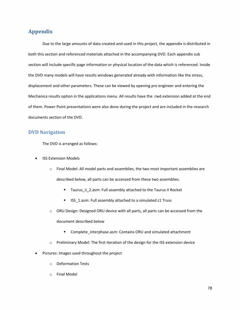
78
Appendix
Due to the large amounts of data created and used in this project, the appendix is distributed in
both this section and referenced materials attached in the accompanying DVD. Each appendix sub
section will include specific page information or physical location of the data which is referenced. Inside
the DVD many models will have results windows generated already with information like the stress,
displacement and other parameters. These can be viewed by opening pro engineer and entering the
Mechanica results option in the applications menu. All results have the .rwd extension added at the end
of them. Power Point presentations were also done during the project and are included in the research
documents section of the DVD.
DVD Navigation
The DVD is arranged as follows:
ISS Extension Models
o Final Model: All model parts and assemblies, the two most important assemblies are
described below, all parts can be accessed from these two assemblies.
Taurus_ii_2.asm: Full assembly attached to the Taurus II Rocket
ISS_1.asm: Full assembly attached to a simulated z1 Truss
o ORU Design: Designed ORU device with all parts, all parts can be accessed from the
document described below
Complete_interphase.asm: Contains ORU and simulated attachment
o Preliminary Model: The first iteration of the design for the ISS extension device
Pictures: Images used throughout the project
o Deformation Tests
o Final Model

79
o FNF
o ORU
o Radiator
o Scale Model Assembly
o Truss Structure Design
Pro Mechanica Tutorials: Completed tutorials for Pro Mechanica , Piping and Cabling
Research Documents: Documents pertinent to the design phase
o ORU Research Documents
o Taurus II User Guide
Test Results and Parts: Parts and test results for several Mechanica simulations
o Beam Tests
o Deformation Test
o Full Model Tests
Videos
A.1 Taurus II
The complete Taurus II User Guide is included in the DVD at the path: VASIMR ISS EXTENSION
DESIGN\Research Documents\Taurus II User Guide
The pin distribution for the electrical interphase is located in chapter 5 the document.
The thermal, acceleration, vibration and other launch conditions are included in chapter 4, of
the document.
A.2 Displacement Test Results
The displacement tests and parts are found in the path: VASIMR ISS EXTENSION DESIGN\Test
Results and Parts\Deformation Test

80
Saved Results windows can be found in the same path
Pictures of these results are found in the path: VASIMR ISS EXTENSION
DESIGN\Pictures\Deformation Tests
An excel document showing the calculation process is also located inside the folder containing
the deformation test results.
A.3 Beam Truss Structure Results
The results for these tests are found in: VASIMR ISS EXTENSION DESIGN\Test Results and
Parts\Beam Tests (Orientation, Cross Section)
Saved result windows can be found in the same path
Pictures for these results can be found in: VASIMR ISS EXTENSION DESIGN\Pictures\Truss
Structure Design

81
A.4 ORU
All parts for the ORU unit can be found in: VASIMR ISS EXTENSION DESIGN\ISS Extension
Models\ORU Design
Pictures for the ORU can be found in: VASIMR ISS EXTENSION DESIGN\Pictures\ORU

82
A.5 Scale Model Construction
Ad Astra is currently in the process of creating a full scale mockup of the extension device
including all components, but have no experience in constructing these types of models. In order to gain
some insight into the process of creating models, a 1/10 scale reproduction was constructed for this
project. The entire structure had to be created using only materials and tools found in the shop, plus a
small budget to buy any other materials necessary. The model was created using extruded aluminum
parts, drawer rails, rivets, foam board, and silicone glue.
The first step in constructing the design was to scale down the original parts to 1/10 of their
size. The original drawings use millimeters as their unit, so in order to scale the model, the decimal point
was moved. A part which originally would have been 2500mm would now measure 250mm or 25cm.
After this was completed, a parts list was created using the dimensions for the box. The box was built
out of extruded aluminum parts so the total amounts of materials needed had to be calculated from the
design. The aluminum was purchased in three shapes, an L-Beam, a square tube and beams with various
different thicknesses. The sides of the boxes would be constructed using the L-Beams, following the
original design, while the cross members would be constructed using the hollow beams instead of the I-
Beams used in the original design. This was due to the fact that extruded I-Beams were not available in
the small size that was required for the model. All of the parts were attached together using rivets and a
manual rivet machine. The beams on the VASIMR Bay were created using the hollow beams, as the
original design requires.
The first step in the construction was to build the two drawers which would make the truss
extension device. The L-Beams were all cut using the workshops band saw and their edges were
smoothed with the bench grinder. One problem persistent in using the bench grinder is that aluminum
will stick to the stone, which was kept clean by grinding a steel part every once in a while. Once the

83
parts were cut, they had to be attached together in perfect 90 degree angles to create the box. This was
done using a right angle steel ruler. Figure 54 shows both the front and back face of the first box
assembled with the printed plans.
Once the front and back were assembled, the sides of the box needed to be attached. This was
done by stretching an L-Beam from the front to the back of the box. In order to ensure that the box had
perfect 90 degree angles, a ruler was attached to the metal table with clamps and four holes were
drilled on each of the faces of the L-Beam. Rivets were used to secure the beams together and create
the perfect fit. Figure 55 shows the alignment assembly attached to the table with the L-Beams creating
a 90 degree angle. Figure 56 shows the rivet holes and the complete box.
Figure 56: Alignment assembly with close up
Figure 55: Front and back of the first box
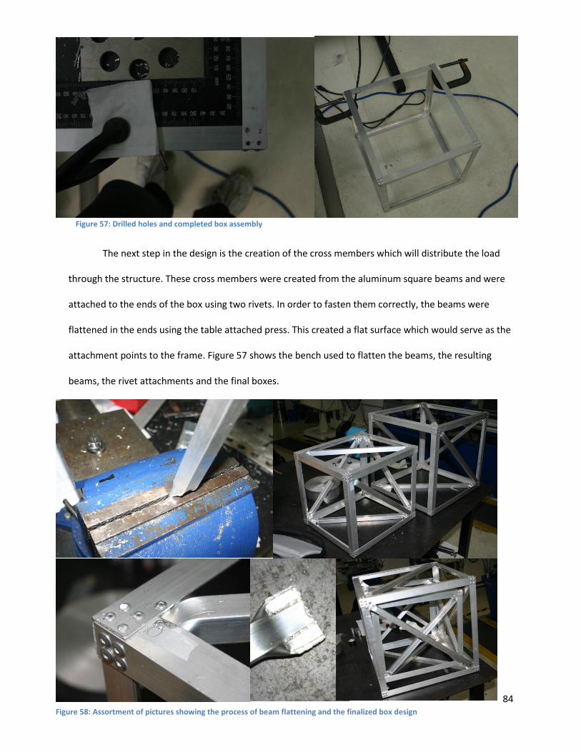
84
The next step in the design is the creation of the cross members which will distribute the load
through the structure. These cross members were created from the aluminum square beams and were
attached to the ends of the box using two rivets. In order to fasten them correctly, the beams were
flattened in the ends using the table attached press. This created a flat surface which would serve as the
attachment points to the frame. Figure 57 shows the bench used to flatten the beams, the resulting
beams, the rivet attachments and the final boxes.
Figure 57: Drilled holes and completed box assembly
Figure 58: Assortment of pictures showing the process of beam flattening and the finalized box design

85
Once the boxes have been manufactured, they need to be attached together in order to make
them extend while holding the VASIMR bay inside them. In order to do this, a set of rails was purchased
and attached to the assembly. The clearances on between the boxes needed to be close enough to fit
the rails without causing them to bend. In order to achieve the correct placement of the rails, spacers
were used to connect both rails. The railing was attached together using rivets as well and aligned to be
straight using a bubble level. The finalized device was able to extend the required distance without
colliding into any surfaces. Figure 58 shows the clearance between the two boxes, the rail attachment
and alignment process and the finalized device both contracted and extended.
Figure 59: Rail attachment process, clearances and final design

86
The next step in the creation of the scale model was the construction of the VASIMR bay. This
was done using the hollow beams and creating a series of interconnecting boxes. To connect the beams
together, L rivet attachments were created as shown in figure 53. Each face of the attachment contained
four rivets. The top of the second box was fitted with railing which would extend the device to the
required location. The bay was fitted with a hinge which attached to the railing, allowing for the tilt
necessary for the correct placement of the bay. Figure 59 shows the bay construction process.
Figure 60: Scale model construction