Catalogue Disco variable speed drives / Compact units / Variable ...
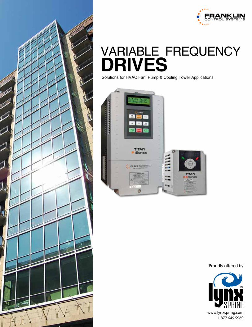
VARIABLE FREQUENCYDRIVES Solutions for HVAC Fan, Pump & Cooling Tower Applications
Proudly offered by
www.lynxspring.com1.877.649.5969

P Series
GS Series
7.5–40HP (200~230VAC), 7.5–400HP (380~480VAC), 3ØDual Rated for Constant & Variable TorqueSensorless & VF Control, Integrated PID Control
P-Series VFD ....................................................6
P-Series Bypass ................................................. 10
N1 P-Series Enclosed with Disconnect ..........12
Enclosed P-Series VFD ..................................... 14
Energy Management Bypass ........................... 16
Redundant Drive Package ...............................22
Compact GS-Series VFD ............................. 26
Enclosed GS-Series VFD ................................... 29
GS-Series Bypass ................................................30
0.5–5HP200~230VAC, 380~480VAC, 3ØDual Rated for Constant & Variable TorqueSensorless & VF Control, Integrated PID Control
SAFETY FIRST! As with all electrical equipment, only qualified, expert personnel should perform maintenance and installation. Comply with all applicable local and national codes and laws that regulate the installation and operation of equipment and read manuals thoroughly. Use only installation manuals and not this sales brochure for installation procedures. It is up to the installer to determine product suitability for a given application.
© 2013 Franklin Control Systems. Product improvement is a continual process. Pricing and specifications subject to change without notice. Marketing materials should not be relied upon for technical specification. Cerus, Mira, Orion, Titan and associated logos are trademarks of Cerus Industrial, Inc. All sales subject to Cerus Terms and Conditions.
COVER: The Wyatt - Portland, OR
Horsepower RangeVoltage Ratings Frequency Ranges
Input Output Input Output
1~400HP 3Ø, 200~230V (+10%, -15%)3Ø, 380~480V (+10%, -15%)
3Ø, 200~230V3Ø, 380~480V 50-60Hz 0-120Hz
Horsepower RangeVoltage Ratings Frequency Ranges
Input Output Input Output
1/4~5HP 3Ø, 200~230V (+10%, -15%)3Ø, 380~480V (+10%, -15%)
3Ø, 200~230V3Ø, 380~480V 50-60Hz 0-400Hz

P-Series, GS-Series ...................................... 38
P-Series, GS_Series UL Type 1 Bypass ........... 39
EMB UL Type 1 Bypass ......................................40
EMB UL Type3R Bypass .................................... 40
P-Series UL Type 1 RDP ..................................... 41
P-Series, GS_Series UL Type 3R Bypass ..........42
P-Series, GS_Series UL Type 12 Enclosed ...... 43
P-Series, GS_Series UL Type 3R Enclosed ......44
Cooling Tower Panel ..........................................45
Optimized Line Reactors ............................. 46
Drive Output Reactors & Filters ..................... 47
Gage Pressure Sensors .....................................48
Differential Pressure Transducers ...................49
Cooling Tower Panel ................................... 32
Tower IQ ............................. 32
Single point Connection Cooling TowersStand alone or Slave Operation OptionsScalable to meet any application
Cooling Tower Controls
Reactors, Filters, and Sensors
Dimensions
Horsepower RangeVoltage Ratings Frequency Ranges
Input Output Input Output
1~400HP 3Ø, 200~230V (+10%, -15%)3Ø, 380~480V (+10%, -15%)
3Ø, 200~230V3Ø, 380~480V 50-60Hz 0-120Hz
5.91”
6.17”
A
C
B

P Series
800.962.3787 | FAX: 503.643.4925 | www.franklin-controls.com
Selectable Applications Include: � Exhaust Fan � Supply Fan � Cooling Tower � Circulating Pump � Submersible Pump � Basic Set Up
Parameters are displayed in plain english on our easy-to-use interface
The Start Up that won’t slow you down.Introducing FastApp™ firmware for the Cerus P Series VFD.
FCS’ FastApp™ Application Based Commissioning makes start-up easier than ever. Select your application (listed below) and the
parameters are automatically adjusted based on industry standards. After that, you’re only a few easy steps from getting your motor
up and running.
Other Features Include: � Dual PID Control � Selectable Units
� Belt Loss Protection � Damper Control Relay � Multi-Motor / Lead-Lag Control
� Broken Pipe Protection
- PSI, °F, °C, inWC, inM, Bar, mBar, Pa, kPa
- VFD can start or stop up to 4 auxiliary motors, soft starts or VFDs

Optimized for Fans & PumpsEveryone knows variable frequency drives (VFDs) can save you money by varying motor speed to match demand. But ramping up and down is just the beginning of energy savings with Franklin Control Systems.
Our automatic energy saving mode minimizes energy losses with varying loads by optimizing flux control for higher efficiency. In PID mode, sleep and wake up functions can deactivate the inverter under low demand conditions and wake it up when demand rises for additional savings. It also extends the life of the motor and drive.
And space vector modulation gives you a super clean sine wave—much better than a typical VF drive. And that translates to cooler running motors, less losses, and a better system.
Reliability Backed with a 5-Year WarrantyJust because our drives are soft on energy, doesn’t mean they aren’t rugged. Check out our high torque ratings—they’re up to the task. And our VFDs are loaded with features that keep them online. They’re able to preheat windings in damp conditions to prevent costly motor and inverter damage. Since power is never perfect, we use the inertia of the load to regenerate power to keep the drive riding through sags. Starting into a spinning fan? No problem. Flying start protection matches the drive to the load for smooth, trip free starts.
When you couple all of these protective features with rugged construction, it’s easy to see why we aren’t afraid to back our drives with a 5-year warranty in variable torque applications.
So easy to set up, you don’t have to pay for factory commissioningOur parameters are straight forward. Keypads are intuitive. Fact is, once you’ve set one up, you’re hooked. Auto tuning takes all the guesswork out of commissioning for fans and pumps.
Engineered for HVAC applications - Delivered on time to meet the demands of your project scheduleTrue 3-contactor bypasses for critical applications. Or better, fully redundant duplex panels so that one drive picks up right where the other left off—keeping duct work intact and tenants comfortable. Or just keep it simple; we offer cost-effective drive/disconnect packages as well.
Line reactors, filtering, we do it all. Rainproof, air conditioned, water proof enclosures. We know what outdoor installations call for and we’ll deliver the goods competitively and quickly.
Our cooling tower packages deliver reliability, ease of installation and energy savings. We incorporate all the
functionality into a single, clean, rugged panel. The net result is a compact control that’s easy to install. Just one power source for reduced installation costs, easy operation, and a job well done.
ENERGY SAVINGS for Fans & Pumps.Backed by an Unprecedented 5-Year Warranty.
P Series
Damper Control
Conventionalinverter control
Titan P-Series

6
VARIABLE FREQUENCY DRIVES
P-Series VFD1–40HP (200~230VAC), 7.5–400HP (380~480VAC), 3ØDual Rated for Constant & Variable TorqueIntegrated PID Control
The 32-character backlit LCD screen displays the drive’s operational status and parameter settings. A very easy drive to set up.
The P-Series’ clearly marked terminal inputs and outputs allow for easy wiring and setup.
New Firmware makes setup a snap � Application based commissioning allows parameters to be automatically set
based on industry standards � Applications: Basic, circulating pump, supply fan, submersible pump & more � Selectable units include PSI, °F, °C, inWC, inM, Bar, mBar, Pa, kPa � Belt loss protection
Space Vector control for efficiency and long motor life � Cleaner sine wave as compared to typical V/Hz control. Motors run
cooler and last longer Advanced PID control (Pre-PID and Dual PID)
� Maintain a constant control of pressure, flow or water level. This function includes Pre-PID, Sleep and Wake up and output inverse sub-functions
� Dual PID for external PID control or cascade PID control � Multi-Motor
Multi-motor control function
� Control up to 4 motors Automatic energy savings mode
� Adaptive flux control for varying loads (e.g. damper loading) Sleep and wake up function
� Increased energy savings by deactivating drive during low demand Flying start protection
� Prevents trips, rough starts, and drive damage from regenerative power from heavy fan inertia rotation Flux braking algorithm
� Reduces deceleration time for enhanced system efficiency
BACnet® is a registered trademark of ASHRAE.

7
VARIABLE FREQUENCY DRIVES
Energy Savings that makes an environmental difference with every building.
Perfect for fans, pumps and airhandlers.
Pre-heater function
� Used to protect motor and inverter from damage when installed in damp location (e.g. green house).
Automatic carrier frequency change
� Adjusts based on temperature for optimal operation Selectable V/F, Sensorless vector control
� Ideal for any control requirement Long-life condenser & simple framework
� Increased reliability Built-in Modbus RTU communication
� Optional: Profibus-DP, LonWorks, BACnet, Modbus
Specifications
Output ratingsVoltage (V) Three phase, 200~230V, Three phase, 380~480V
Frequency (Hz) 0~120Hz
Input ratingsVoltage (V) Three phase, 200~230V (-15%, +10%), Three phase, 380~480V (-15%, +10%)
Frequency (Hz) 50~60Hz (±5%)Input Power Factor <.95 from no load to full load
Operation
Drive Efficiency >96%Control method V/F control, Sensorless vector control
Frequency setting resolution Digital reference: 0.01Hz (below 99Hz) & 0.1Hz (100Hz and over); Analog reference: 0.06Hz at 60HzFrequency setting accuracy Digital: 0.01% of maximum output frequency; Analog: 0.1% of maximum output frequency
V/F ratio Linear, Square, User V/FOverload capacity 1 minute at 120%, 10 seconds at 150% (with inverse characteristic proportional to time)
Torque boost Auto, Manual (0~15%)Multi-function input terminals Total 8 inputs (programmable)
Analog output 0~10V linear
Input signal
Operator control 32-character LCD keypad, Terminals, ModBus-RTU communication Optional, ProfiBus-DP, DeviceNet, F-Net, BACnet, LonWorks
Frequency setting Analog: 0~10V, 4~20mA, additional port for Sub-Board (0~10V); Digital: Keypad, CommunicationStart signal Forward, Reverse
Multi-step operation Setting up to 17 speeds (using multi-function terminal)
Multi-step accel/decel time 0.1~6000 seconds. Maximum 8 pre-defined steps using multi-function terminals
Operational functions
DC braking, Frequency limit, Frequency jump, Second motor function, Slip compensation, Reverse rotation prevention, Auto restart, Inverter bypass, Auto-tuning, Dual PID control
Emergency stop Stops output from inverterAuto operation Operates from internal sequence by setting multi-function terminal (5 way x 8 step)
Jog Jog operationFault reset Resets fault signal when protective function is active
Output signalOperational status Frequency detection, Overload alarm, Stall, Overvoltage, Undervoltage, Inverter overheat, Run, Stop, Constant speed,
Speed search, Fault output, Inverter bypass, Auto-operation sequence
Indicator Output frequency, Output current, Output voltage, DC voltage, Output torque (output voltage: 0~10V)
Protective functionsTrip Overvoltage, Undervoltage, Overcurrent, Inverter overheat, Motor overheat, I/O phase loss, Fuse open, Ground fault,
External fault 1, 2, Option fault, Overload, Speed command loss, Hardware fault, Communication error, etc.
Alarm Stall, Overload Temperature sensor fault
Operating environment
Ambient temperature -10°~40° C (50° C when derated 20%) or 14°~104° F (122° F when derated 20%)Storage temperature -20°~65° C or -4°~149.5° F
Humidity Less than 95% Relative Humidity maximum (non-condensing)vibration Below 5.9m²/sec (=0.6g)Altitude Below 1,000m (3,300ft): Derate VFD by 10% for every additional 1,000m
Application site Pollution degree 2. No corrosive gas, combustible gas, oil mist or dust

8
VARIABLE FREQUENCY DRIVES
P Series Wiring
*For general reference only, not field wiring. Consult installation instructions.

9
VARIABLE FREQUENCY DRIVES
3-Phase, 200~230V P-Series VFDStandard Duty (VT) Heavy Duty (CT)
Part Number 3% Line Reactor*HP kW FLA HP kW FLA
1 1.9 5 0.4 0.95 2.5 CI-001-P2 KDRULA25LE01
2 3 8 0.75 1.9 5 CI-002-P2 KDRULA27LE01
3 4.6 12 1.5 3 8 CI-003-P2 KDRULA28LE01
5 6.1 16 2.2 4.6 12 CI-005-P2 KDRULB22LE01
7.5 5.5 24 5 3.7 17 CI-007-P2 KDRULB23LE01
10 7.5 32 7.5 5.5 23 CI-010-P2 KDRULD25LE01
15 11 46 10 7.5 33 CI-015-P2 KDRULD24LE01
20 15 60 15 11 44 CI-020-P2 KDRULD26LE01
25 18.5 74 20 15 54 CI-025-P2 KDRULC22LE01
30 22 88 25 18.5 68 CI-030-P2 KDRULF24LE01
40 30 115 30 22 84 CI-040-P2 KDRULF25LE01
3-Phase, 380~480V P-Series VFDStandard Duty (VT) Heavy Duty (CT)
Part Number 3% Line Reactor*HP kW FLA HP kW FLA
1 2 2.5 0.4 1 1.25 CI-001-P4 KDRULA8LE01
2 3.2 4 0.75 2 2.5 CI-002-P4 KDRULA1LE01
3 4.8 6 1.5 3.2 4 CI-003-P4 KDRULA2LE01
5 6.4 8 2.2 4.8 6 CI-005-P4 KDRULA3LE01
7.5 5.5 12 5 3.7 8 CI-007-P4 KDRULA4LE01
10 7.5 16 7.5 5.5 11 CI-010-P4 KDRULA5LE01
15 11 24 10 7.5 17 CI-015-P4 KDRULB2LE01
20 15 30 15 11 22 CI-020-P4 KDRULB1LE01
25 18.5 39 20 15 28 CI-025-P4 KDRULD1LE01
30 22 45 25 18.5 34 CI-030-P4 KDRULD2LE01
40 30 61 30 22 44 CI-040-P4 KDRULC1LE01
50 37 75 40 30 55 CI-050-P4 KDRULF2LE01
60 45 91 50 37 66 CI-060-P4 KDRULF4LE01
75 55 110 60 45 80 CI-075-P4 KDRULF3LE01
100 75 152 75 55 111 CI-100-P4 KDRULH3LE01
125 90 183 100 75 134 CI-125-P4 KDRULH2LE01
150 110 223 125 90 183 CI-150-P4 KDRULH1LE01
200 132 264 150 110 223 CI-200-P4 KDRULG3LE01
250 160 325 200 132 264 CI-250-P4 KDRULG1LE01
350 220 432 250 160 325 CI-350-P4 KDRULJ2LE01
400 280 547 300 220 432 CI-400-P4 KDRULJ1LE01
OptionsPart Number Description
CI-RKPK-EXT2M-P/S Remote Keypad Mounting Kit (2 Meter Cable)
CI-RKPK-EXT3M-P/S Remote Keypad Mounting Kit (3 Meter Cable)
CI-RKPK-EXT5M-P/S Remote Keypad Mounting Kit (5 Meter Cable)
CI-R4-COM RS485 communication card
CI-BN-COM BACnet communication card
CI-LWP-COM Lonworks communication card
CI-N2-COM N2 communication card
* Line Reactors housed in separate UL Type 1 Enclosure
* Line Reactors housed in separate UL Type 1 Enclosure

10
VARIABLE FREQUENCY DRIVES
P-Series Bypass1–40HP (200~230VAC), 7.5–400HP (380~480VAC), 3ØDrive Isolation OptionIndoor & Outdoor Enclosure Options
Standard bypass features � Compact vertical design preserves wall space � Includes standard MMS disconnect, Hand/Off/Auto &
VFD/Off/Bypass switches � Fireman’s override/smoke purge ready � Choose from 2 or 3 contactor configurations � UL 508C rating for maximum motor protection
Wide range of design options � Door mounted control options for manual speed pot,
LED pilot lights and more � Input circuit breaker � Optional installed input or output drive reactors � Integrated electronic overload for full phase protection
in bypass mode � Panel space heaters available for ambient
temperatures below 32°F
Enclosure options for any environment � A variety of NEMA rated enclosures to meet application
requirements (Stainless, fiberglass, watertight, etc.) � Weatherproof, white powdercoat Type 3R enclosure for
rooftop and outdoor mounting.
Installs in minutes, lasts a lifetime.
The easy to use 4-direction keypad makes settings a snap.

11
VARIABLE FREQUENCY DRIVES
3-Phase, 200~230V P-Series VFD Bypass
Standard duty (VT)
Bypass with Drive Isolation (3-Contactor Bypass Equivalent) 2-Contactor Bypass Line Reactor Options
HP kW Rating UL Type 1 UL Type 3R UL Type 1 UL Type 3R Installed 3% Installed 5%
1 1.9 CIE1-BYP001-P2/3 CIE3R-BYP001-P2/3 CIE1-BYP001-P2 CIE3R-BYP001-P2 VFD-KDRA25L VFD-KDRA25H
2 3 CIE1-BYP002-P2/3 CIE3R-BYP002-P2/3 CIE1-BYP002-P2 CIE3R-BYP002-P2 VFD-KDRA27L VFD-KDRA26H
3 4.6 CIE1-BYP003-P2/3 CIE3R-BYP003-P2/3 CIE1-BYP003-P2 CIE3R-BYP003-P2 VFD-KDRA28L VFD-KDRA28H
5 6.1 CIE1-BYP005-P2/3 CIE3R-BYP005-P2/3 CIE1-BYP005-P2 CIE3R-BYP005-P2 VFD-KDRB22L VFD-KDRB25H
7.5 5.5 CIE1-BYP007-P2/3 CIE3R-BYP007-P2/3 CIE1-BYP007-P2 CIE3R-BYP007-P2 VFD-KDRB23L VFD-KDRB26H
10 7.5 CIE1-BYP010-P2/3 CIE3R-BYP010-P2/3 CIE1-BYP010-P2 CIE3R-BYP010-P2 VFD-KDRD25L VFD-KDRD21H
15 11 CIE1-BYP015-P2/3 CIE3R-BYP015-P2/3 CIE1-BYP015-P2 CIE3R-BYP015-P2 VFD-KDRD24L VFD-KDRD22H
20 15 CIE1-BYP020-P2/3 CIE3R-BYP020-P2/3 CIE1-BYP020-P2 CIE3R-BYP020-P2 VFD-KDRD26L VFD-KDRC22H
25 18.5 CIE1-BYP025-P2/3 CIE3R-BYP025-P2/3 CIE1-BYP025-P2 CIE3R-BYP025-P2 VFD-KDRC22L VFD-KDRF28H
30 22 CIE1-BYP030-P2/3 CIE3R-BYP030-P2/3 CIE1-BYP030-P2 CIE3R-BYP030-P2 VFD-KDRF24L VFD-KDRF25H
40 30 CIE1-BYP040-P2/3 CIE3R-BYP040-P2/3 CIE1-BYP040-P2 CIE3R-BYP040-P2 VFD-KDRF25L VFD-KDRF26H
3-Phase, 380~480V P-Series VFD Bypass
Standard duty (VT)
Bypass with Drive Isolation (3-Contactor Bypass Equivalent) 2-Contactor Bypass Line Reactor Options
HP kW Rating UL Type 1 UL Type 3R UL Type 1 UL Type 3R Installed 3% Installed 5%
1 2 CIE1-BYP001-P4/3 CIE3R-BYP001-P4/3 CIE1-BYP001-P4 CIE3R-BYP001-P4 VFD-KDRA8L VFD-KDRA8H
2 3.2 CIE1-BYP002-P4/3 CIE3R-BYP002-P4/3 CIE1-BYP002-P4 CIE3R-BYP002-P4 VFD-KDRA1L VFD-KDRA1H
3 4.8 CIE1-BYP003-P4/3 CIE3R-BYP003-P4/3 CIE1-BYP003-P4 CIE3R-BYP003-P4 VFD-KDRA2L VFD-KDRA2H
5 6.4 CIE1-BYP005-P4/3 CIE3R-BYP005-P4/3 CIE1-BYP005-P4 CIE3R-BYP005-P4 VFD-KDRA3L VFD-KDRA3H
7.5 5.5 CIE1-BYP007-P4/3 CIE3R-BYP007-P4/3 CIE1-BYP007-P4 CIE3R-BYP007-P4 VFD-KDRA4L VFD-KDRA4H
10 7.5 CIE1-BYP010-P4/3 CIE3R-BYP010-P4/3 CIE1-BYP010-P4 CIE3R-BYP010-P4 VFD-KDRA5L VFD-KDRA5H
15 11 CIE1-BYP015-P4/3 CIE3R-BYP015-P4/3 CIE1-BYP015-P4 CIE3R-BYP015-P4 VFD-KDRB2L VFD-KDRB2H
20 15 CIE1-BYP020-P4/3 CIE3R-BYP020-P4/3 CIE1-BYP020-P4 CIE3R-BYP020-P4 VFD-KDRB1L VFD-KDRC3H
25 18.5 CIE1-BYP025-P4/3 CIE3R-BYP025-P4/3 CIE1-BYP025-P4 CIE3R-BYP025-P4 VFD-KDRD1L VFD-KDRC1H
30 22 CIE1-BYP030-P4/3 CIE3R-BYP030-P4/3 CIE1-BYP030-P4 CIE3R-BYP030-P4 VFD-KDRD2L VFD-KDRE2H
40 30 CIE1-BYP040-P4/3 CIE3R-BYP040-P4/3 CIE1-BYP040-P4 CIE3R-BYP040-P4 VFD-KDRC1L VFD-KDRF4H
50 37 CIE1-BYP050-P4/3 CIE3R-BYP050-P4/3 CIE1-BYP050-P4 CIE3R-BYP050-P4 VFD-KDRF2L VFD-KDRF1H
60 45 CIE1-BYP060-P4/3 CIE3R-BYP060-P4/3 CIE1-BYP060-P4 CIE3R-BYP060-P4 VFD-KDRF4L VFD-KDRF2H
75 55 CIE1-BYP075-P4/3 CIE3R-BYP075-P4/3 CIE1-BYP075-P4 CIE3R-BYP075-P4 VFD-KDRF3L VFD-KDRH2H
100 75 CIE1-BYP100-P4/3 CIE3R-BYP100-P4/3 CIE1-BYP100-P4 CIE3R-BYP100-P4 VFD-KDRH3L VFD-KDRH1H
125 90 CIE1-BYP125-P4/3 CIE3R-BYP125-P4/3 CIE1-BYP125-P4 CIE3R-BYP125-P4 VFD-KDRH2L VFD-KDRG3H
OptionsPart Number Description
VFD-RPL* Run Pilot Light (Green Standard)
VFD-BPL* Bypass Pilot Light (Amber Standard)
VFD-FPL* Fault Pilot Light (Red Standard)
VFD-SPD Door Mounted Speed Potentiometer
VFD-EOL Solid-state Bypass Overload
VFD-LTA Lightning Arrestor
CI-BN-COM BACnet communication card
CI-LWP-COM Lonworks communication card
CI-N2-COM N2 communication card
VFD-ABYP-R Drive auto bypass with relay
VFD-KPD/4X Door Mounted Keypad with Type 4X Cover
* Select 24V or 120V based on package control voltage. For UL Type 1 select 24V. For UL Type 3R & 12 select 120V.

12
VARIABLE FREQUENCY DRIVES
1–30HP (200~230VAC), 1–40HP (380~480VAC), 3ØDual Rated for Constant & Variable TorqueIntegrated PID Control
N1 P-Series Enclosed with Disconnect
Easy Installation, Time Saving Design � Reduces labor costs � Attractive, mated design � MMS disconnect � Fireman’s override/smoke purge capable � UL 508C rating with all drive models
for maximum motor protection � Optional input drive reactor, HOA switch, manual speed
potentiometer, and communications Rugged disconnect includes padlock provisions.
The 32-character backlit LCD screen displays the drive’s operational status and parameter settings. A very easy drive to set up.
A
B C
Dimensions
P-Series Drive with Disconnect H x W x D, (A x B x C)
CIE1-ED001-P2/D ~ CIE1-ED015-P4/D 24.50”x 8.00” x 8.12”
CIE1-ED020-P2/D ~ CIE1-ED020-P4/D 32.50” x 9.97” x 8.70”
CIE1-ED025-P2/D ~CIE1-ED040-P4/D 40.00” x 12.17” x 9.97”

13
VARIABLE FREQUENCY DRIVES
3-Phase, 200~230V P-Series VFDStandard Duty (VT)
Part Number 3% Line ReactorHP kW FLA
1 0.75 5 CIE1-ED001-P2/D VFD-KDRA25L
2 1.5 8 CIE1-ED002-P2/D VFD-KDRA27L
3 2.2 12 CIE1-ED003-P2/D VFD-KDRA28L
5 3.7 16 CIE1-ED005-P2/D VFD-KDRB22L
7.5 5.5 24 CIE1-ED007-P2/D VFD-KDRB23L
10 7.5 32 CIE1-ED010-P2/D VFD-KDRD25L
15 11 46 CIE1-ED015-P2/D VFD-KDRD24L
20 15 60 CIE1-ED020-P2/D VFD-KDRD26L
25 18.5 74 CIE1-ED025-P2/D VFD-KDRC22L
30 22 88 CIE1-ED030-P2/D VFD-KDRF24L
3-Phase, 380~480V P-Series VFDStandard Duty (VT)
Part Number 3% Line ReactorHP kW FLA
1 0.75 2.5 CIE1-ED001-P4/D VFD-KDRA8L
2 1.5 4 CIE1-ED002-P4/D VFD-KDRA1L
3 2.2 6 CIE1-ED003-P4/D VFD-KDRA2L
5 3.7 8 CIE1-ED005-P4/D VFD-KDRA3L
7.5 5.5 12 CIE1-ED007-P4/D VFD-KDRA4L
10 7.5 16 CIE1-ED010-P4/D VFD-KDRA5L
15 11 24 CIE1-ED015-P4/D VFD-KDRB2L
20 15 30 CIE1-ED020-P4/D VFD-KDRB1L
25 18.5 39 CIE1-ED025-P4/D VFD-KDRD1L
30 22 45 CIE1-ED030-P4/D VFD-KDRD2L
40 30 61 CIE1-ED040-P4/D VFD-KDRC1L
OptionsPart Number Description
VFD-HOA Hand/Off/Auto switch
VFD-SPD Door Mounted Speed Potentiometer
CI-R4-COM RS485 communication card
CI-BN-COM BACnet communication card
CI-LWP-COM Lonworks communication card
CI-N2-COM N2 communication card
For single phase sizing consult factory - 800.962.3787

14
VARIABLE FREQUENCY DRIVES
2–40HP (200~230VAC), 7.5–400HP (380~480VAC), 3ØDual Rated for Constant & Variable TorqueIntegrated PID Control
Enclosed P-Series VFD
Designed to Withstand Harsh Environments � 3R or UL Type 12 packaging for outdoor and/or wash down applications � Additional application-specific protective options
- Lightning/Surge Arrestor - Line Reactors - Load Reactors - dV/dT Filter
� Rainproof UL Type 3R enclosure reduces thermal absorption with white, solar reflective finish and filtered cooling fans
� Standard enclosed VFD package is rated for 92° F outside temperature, non-direct sunlight � Attain up to 110° F outside temperature, non-direct sunlight by de-rating VFD
Functionality � A single VFD has the capability to control up to four additional motors reducing the need for
additional controls
� Sleep mode reduces energy consumption by stopping motors during periods of low demand � Flexible sensor inputs accept 0-10VDC and 4-20mA analog signals � VFD provides additional 12VDC and 24VDC power for sensors � PID control and Pre-PID mode with time delay reduces water hammer and cavitation
while providing precise system control � Dual PID control for external PID control of a secondary system
UL Type 12
UL 3R

15
VARIABLE FREQUENCY DRIVES
3-Phase, 200~230V Enclosed Packages Standard Duty (VT)
1Ø HP* 3Ø HP FLA UL Type 3R UL Type 12 3% Line Reactor Output Reactor Output Filter
2 5 24 CIE3R-ED005-P2 CIE12-ED005-P2 VFD-KDRB22L VFD-KDRD1P VFD-V1K16A00
3 7.5 24 CIE3R-ED007-P2 CIE12-ED007-P2 VFD-KDRB23L VFD-KDRD2P VFD-V1K25A00
5 10 32 CIE3R-ED010-P2 CIE12-ED010-P2 VFD-KDRD25L VFD-KDRD3P VFD-V1K35A00
7.5 15 46 CIE3R-ED015-P2 CIE12-ED015-P2 VFD-KDRD24L VFD-KDRC1P VFD-V1K45A00
10 20 60 CIE3R-ED020-P2 CIE12-ED020-P2 VFD-KDRD26L VFD-KDRF1P VFD-V1K55A00
10 25 74 CIE3R-ED025-P2 CIE12-ED025-P2 VFD-KDRC22L VFD-KDRF2P VFD-V1K80A00
15 30 88 CIE3R-ED030-P2 CIE12-ED030-P2 VFD-KDRF24L VFD-KDRF3P VFD-V1K80A00
20 40 115 CIE3R-ED040-P2 CIE12-ED040-P2 VFD-KDRF25L VFD-KDRH1P VFD-V1K110A00
3-Phase, 380~480V Enclosed PackagesStandard Duty (VT)
1Ø HP* 3Ø HP FLA UL Type 3R UL Type 12 3% Line Reactor Output Reactor Output Filter
2 5 12 CIE3R-ED005-P4 CIE12-ED005-P4 VFD-KDRA3L VFD-KDRA3P VFD-V1K8A00
3 7.5 12 CIE3R-ED007-P4 CIE12-ED007-P4 VFD-KDRA4L VFD-KDRA4P VFD-V1K12A00
5 10 16 CIE3R-ED010-P4 CIE12-ED010-P4 VFD-KDRA5L VFD-KDRB1P VFD-V1K18A00
7.5 15 24 CIE3R-ED015-P4 CIE12-ED015-P4 VFD-KDRB2L VFD-KDRD1P VFD-V1K21A00
10 20 30 CIE3R-ED020-P4 CIE12-ED020-P4 VFD-KDRB1L VFD-KDRD2P VFD-V1K27A00
10 25 39 CIE3R-ED025-P4 CIE12-ED025-P4 VFD-KDRD1L VFD-KDRD3P VFD-V1K35A00
15 30 45 CIE3R-ED030-P4 CIE12-ED030-P4 VFD-KDRD2L VFD-KDRD4P VFD-V1K45A00
20 40 61 CIE3R-ED040-P4 CIE12-ED040-P4 VFD-KDRC1L VFD-KDRC1P VFD-V1K55A00
20 50 75 CIE3R-ED050-P4 CIE12-ED050-P4 VFD-KDRF2L VFD-KDRF1P VFD-V1K80A00
20 60 91 CIE3R-ED060-P4 CIE12-ED060-P4 VFD-KDRF4L VFD-KDRF2P VFD-V1K80A00
20 75 110 CIE3R-ED075-P4 CIE12-ED075-P4 VFD-KDRF3L VFD-KDRF3P VFD-V1K110A00
20 100 152 CIE3R-ED0100-P4 CIE12-ED100-P4 VFD-KDRH3L VFD-KDRH1P VFD-V1K130A00
20 125 183 CIE3R-ED0125-P4 CIE12-ED125-P4 VFD-KDRH2L VFD-KDRI1P VFD-V1K160A00
OptionsPart Number Description
VFD-RPL* Run Pilot Light (Green Standard)
VFD-FLT* Fault Pilot Light (Red Standard)
VFD-HOA Hand/Off/Auto Switch
VFD-SPD Door Mounted Speed Potentiometer
VFD-LTA Lightning Arrestor
VFD-KPD Door Mounted Keypad
VFD-KPD/4X Door Mounted Keypad with Type 4X Cover
Ordering and Sizing Information
* Maximum HP of 3-phase motor in single phase power applications
* Maximum HP of 3-phase motor in single phase power applications
* Select 24V or 120V based on package control voltage. For UL Type 1 select 24V. For UL Type 3R & 12 select 120V.

16
VARIABLE FREQUENCY DRIVES
1–40HP (200~230VAC), 1–400HP (380~480VAC), 3Ø2 & 3 Contactor VariationsAccurate Metering via BACnetIndoor & Outdoor Enclosure Options
Energy Management Bypass (EMB) features
� ANSI grade power meter in bypass and VFD mode � Phase loss, phase unbalance, UL 1053 ground fault, and
OV/UV protection for VFD and bypass � Integrated BACnet control and keypad for bypass � Fireman’s override/smoke purge ready � Belt loss protection and fault alarm in bypass mode � Damper and valve control through EM-Bypass and VFD � Dual action 3% input line reactor - harmonic mitigation
for IEEE 519 and transient voltage spike protection
� Input MCP disconnect
Wide range of design options
� Door mounted control options for manual speed pot, LED lights and more
� Compact vertical design preserves wall space (UL Type 1) � Weatherproof enclosures are powder coated white to
reflect heat (UL Type 3R) � Optional Electronic Overload for full phase protection in
bypass mode � Panel space heaters available for ambient temperatures
below 0°C ( 32°F) (UL Type 3R)
Enclosure options for any environment
� A variety of NEMA rated enclosures to meet application requirements (Stainless, fiberglass, watertight, etc.)
� Derated NEMA 3R for 110°F ambient temperature rating in white powdercoat, weatherproof enclosure
� AC cooled VFD options for extreme heat installations
®Native for VFD and BypassBACnet™ is a registered trademark of ASHRAE
Energy Management BypassB
New FastApp™ Firmware makes setup a snap � Application based commissioning allows parameters to
be automatically set based on industry standards � Applications: Basic, circulating pump, supply fan,
submersible pump & more � Selectable units include PSI, °F, °C, inWC, inM, Bar, mBar,
Pa, kPa
� Belt loss protection
Other standard VFD features � Space Vector Pulse Width Modulation control for
efficiency and long motor life � Advanced PID control (Pre-PID and Dual PID) � Multi-motor funtion controls up to 4 motos � Automatic energy savings mode � Sleep and wake up function � Flying start protection � Flux breaking algorithm � Automatic carrier frequency change � Selectable V/F, sensorless vector control � Built-in Modbus RTU communication
P Series VFD Specific FeaturesGeneral Features
Advanced Protection & Metering in VFD or Bypass Mode

17
VARIABLE FREQUENCY DRIVES
Specifications
General
Output Frequency .01~120 Hz
Input Freqency 50/60 Hz (± 5%)
Output Voltage P2 Models: 200VAC~230VAC P4 Models: 380VAC~480VAC
Input Voltage P2 Models: 200VAC (-15%)~230VAC (+10%)P4 Models: 380VAC (-15%)~480VAC (+10%)
Cooling Method Forced air cooling by internal fans
Short Circuit Rating 100 kA, suitable for use on a circuit capable of delivering not more than 65,000 RMS symmetrical Short Circuit Amperes
Agency Approvals UL and cUL listed, CE marked
Control
Control Method V/F, Slip Compensation, Sensorless Vector w/ auto tune (no encoder required)
Frequency Setting Resolution Digital Reference: 0.01 Hz (Below 100 Hz), 0.1 Hz (Over 100 Hz)Analog Reference: 0.01 Hz / 60 Hz
Frequency Accuracy Digital: 0.01 % of Max. Output FrequencyAnalog: 0.1 % of Max. Output Frequency
V/F Control Curve Linear, S-Pattern, User Defined Pattern
Overload Capacity 110 % per 1 min variable torque150% per 1 min constant torque (20% de-rated VFD)
Torque Boost Manual Torque Boost Adjustment (0 ~ 15 %), Auto Torque Boost
Operation
Operation Method Keypad / Terminals / Communication
Frequency Setting Analog: 0 ~ 10VDC, ±10VDC, 4 ~ 20mA / Pulse Frequency / Ext-PIDDigital: Keypad
Inpu
ts
Start Signal Forward or Reverse
Multi-Step Up to 18 Speeds can be set including Jog (Use binary coded combinations of Programmable Digital Inputs)
Multi-StepAccel/Decel Time 0.1~ 6,000 sec, Max 4 types can be set via Multi- Function Terminals. Accel/Decel Pattern: Linear, U-Curve or S-Curve
Emergency Stop Immediately Interrupts the VFD Output in any control method
Jog Jog Operation with adjustable Jog frequency
Fault Reset Resets VFD. Some critical faults can only be reset by recycling the VFD power.
Out
puts
Four Multifunction Relays Each relay can be set to Frequency Detection Level, Overload Alarm, Stalling, Over Voltage, Low Voltage, VFD Overheating/ Running/ Stopping/ At Speed, VFD By-Pass, Speed Search etc.
Fault Output Each relay can be set to Frequency Detection Level, Overload Alarm, Stalling, Over Voltage, Low Voltage, VFD Overheating/ Running/ Stopping/ At Speed, VFD By-Pass, Speed Search etc.
Two Analog Outputs Double Throw Relay Contact (3A, 3C, 3B) – 1A up to 250VAC or 30VDC
Operation Functions Selections: Output Frequency, Output Current, Output Voltage, Output kW, DC Link Voltage. Both outputs are 0-10VDC scalable from 10 to 200%.
ProtectionVFD Fault Trips Over Voltage, Low Voltage, Over Current, Overload Protection, Short Circuit Protection, Ground Fault, VFD Overheat, Motor
Overheat, Output Phase Open, External Trip, CPU Communication Error, Loss of Speed Command, Hardware Fault, etc.
VFD Alarm Stall Prevention, Overload Alarm, Thermal Sensor Fault
Display
Keyp
ad Operation Information Output Frequency, Output Current, Output Voltage, Frequency Set Value, Operating Speed, DC Voltage, kWattmeter, Run-time, Last Trip Time
Fault History The VFD stores 5 last faults with Hz, A, VFD mode and trip time for each fault.
Environment
Ambient Temperature 14°F~ 104°(-10°~ 40°C). De-rate VFD by 20% to increase rating up to 122°
Storage Temperature -4°F~ 149 (-20° ~ 65°C)
Ambient Humidity Up to 95 % RH. (Non-Condensing)
Altitude Max. 3,300ft (1,000m). De-rate VFD 20% for every additional 1000ft.
Vibration Max. 0.6g (5.9m/sec2)
Environmental Conditions Pollution degree 2. No Corrosive Gas, Combustible Gas, Oil Mist or Dust

18
VARIABLE FREQUENCY DRIVES
3-Phase, 200~230V P-Series VFD EMB
Standard duty (VT) EMBass with Drive Isolation (3-Contactor EM-Bypass Equivalent) 2-Contactor EM-Bypass
Disconnect Contactor
HP kW FLA UL Type 1 UL Type 3R UL Type 1 UL Type 3R
1 1.9 6 CIE1-EMP001-P2/3 CIE3R-EMB001-P2/3 CIE1-EMB001-P2 CIE3R-EMB001-P2 CMS-32HI-6 MRC-9B
2 3 8 CIE1-EMB002-P2/3 CIE3R-EMB002-P2/3 CIE1-EMB002-P2 CIE3R-EMB002-P2 CMS-32HI-8 MRC-9B
3 4.6 13 CIE1-EMB003-P2/3 CIE3R-EMB003-P2/3 CIE1-EMB003-P2 CIE3R-EMB003-P2 CMS-32HI-13 MRC-12B
5 6.1 17 CIE1-EMB005-P2/3 CIE3R-EMB005-P2/3 CIE1-EMB005-P2 CIE3R-EMB005-P2 CMS-32HI-17 MRC-18B
7.5 5.5 24 CIE1-EMB007-P2/3 CIE3R-EMB007-P2/3 CIE1-EMB007-P2 CIE3R-EMB007-P2 CMS-32HI-26 MRC-22B
10 7.5 32 CIE1-EMB010-P2/3 CIE3R-EMB010-P2/3 CIE1-EMB010-P2 CIE3R-EMB010-P2 CMS-32HI-40 MRC-40A
15 11 46 CIE1-EMB015-P2/3 CIE3R-EMB015-P2/3 CIE1-EMB015-P2 CIE3R-EMB015-P2 CMS-63HI-50 MRC-40A
20 15 60 CIE1-EMB020-P2/3 CIE3R-EMB020-P2/3 CIE1-EMB020-P2 CIE3R-EMB020-P2 CMS-63HI-63 MRC-50LA
25 18.5 74 CIE1-EMB025-P2/3 CIE3R-EMB025-P2/3 CIE1-EMB025-P2 CIE3R-EMB025-P2 CMS-100HI-90 MRC-65LA
30 22 88 CIE1-EMB030-P2/3 CIE3R-EMB030-P2/3 CIE1-EMB030-P2 CIE3R-EMB030-P2 CMS-100HI-100 MRC-85LA
3-Phase, 380~480V P-Series VFD EMB
Standard duty (VT) EM-Byass with Drive Isolation (3-Contactor EM-Bypass Equivalent) 2-Contactor EM-Bypass
Disconnect Contactor
HP kW FLA UL Type 1 UL Type 3R UL Type 1 UL Type 3R
1 2 2.5 CIE1-EMB001-P4/3 CIE3R-EMB001-P4/3 CIE1-EMB001-P4 CIE3R-EMB001-P4 CMS-32HI-2.5 MRC-9B
2 3.2 4 CIE1-EMB002-P4/3 CIE3R-EMB002-P4/3 CIE1-EMB002-P4 CIE3R-EMB002-P4 CMS-32HI-4 MRC-9B
3 4.8 6 CIE1-EMB003-P4/3 CIE3R-EMB003-P4/3 CIE1-EMB003-P4 CIE3R-EMB003-P4 CMS-32HI-6 MRC-9B
5 6.4 8 CIE1-EMB005-P4/3 CIE3R-EMB005-P4/3 CIE1-EMB005-P4 CIE3R-EMB005-P4 CMS-32HI-8 MRC-9B
7.5 5.5 12 CIE1-EMB007-P4/3 CIE3R-EMB007-P4/3 CIE1-EMB007-P4 CIE3R-EMB007-P4 CMS-32HI-13 MRC-12B
10 7.5 16 CIE1-EMB010-P4/3 CIE3R-EMB010-P4/3 CIE1-EMB010-P4 CIE3R-EMB010-P4 CMS-32HI-17 MRC-18B
15 11 24 CIE1-EMB015-P4/3 CIE3R-EMB015-P4/3 CIE1-EMB015-P4 CIE3R-EMB015-P4 CMS-32HI-22 MRC-22B
20 15 30 CIE1-EMB020-P4/3 CIE3R-EMB020-P4/3 CIE1-EMB020-P4 CIE3R-EMB020-P4 CMS-32HI-32 MRC-32A
25 18.5 39 CIE1-EMB025-P4/3 CIE3R-EMB025-P4/3 CIE1-EMB025-P4 CIE3R-EMB025-P4 CMS-32HI-40 MRC-40A
30 22 45 CIE1-EMB030-P4/3 CIE3R-EMB030-P4/3 CIE1-EMB030-P4 CIE3R-EMB030-P4 CMS-63HI-50 MRC-50LA
40 30 61 CIE1-EMB040-P4/3 CIE3R-EMB040-P4/3 CIE1-EMB040-P4 CIE3R-EMB040-P4 CMS-63HI-63 MRC-50LA
EMB Part Number Selection Tables
*See next page for Disconnect & Contactor Specifications*Contact factory for higher HP applications

19
VARIABLE FREQUENCY DRIVES
EMB Power Wiring
On the P Series VFD, the easy to use 4-direction keypad with FastApp™ makes commissioning a snap.
Full LCD display and keypad control for Energy Management Bypass.

20
VARIABLE FREQUENCY DRIVES
EMB Control Wiring
This revolutionary electronic overload gives your EM-Bypass all the protection, monitoring and control of your motor a VFD would, now in a reliable bypass starter.
CR11
2
A1
A2CR1
24V
CPT
SCM PCB
ActuatorControl
VoltageInputs
RelayOutputs
DryInputs
CommonShutdown(Perm Auto)Auto Run(Perm Auto)
Common
Fault
Status
Fireman’sOverride
Auto Run
Normally Open Input
Normally Closed Input
12-120VAC/DC Input
12-120VAC/DC Input
CAT 5 Input
Common
Motor
Limit Switch
24VAC, 1A Output
L1 L2
TRANSFORMER PRIMARYCIRCUIT BREAKER SIZING
VA 208/230 480V
75VA100VA 2A 1A
1A 0.5A
H1
N
VFD BYPASS
AB2
AB3
DRV
A4
C4
AB1
JAB
DRV
3C
3B3C
3A
CR1
13
14MI-VFD
111
122
MI-BYP121
112VFD
BYP
MI
DRY INPUTD3 D4
RELAYOUTPUT
O3
O4
A+
A-
ANALOGINPUT
S
+
-
RS-485
BACNET PCB DRV(P-SERIES VFD)
VFD43
44
HAND SPEED
0-10VDC
V+
V1
I
AG
+12VDC
+0-10VDC
+4-20mA
COMMON
M7
CM
M1
S0
5G
V+
V1
I
5G
NOTE:1. REMOVE JUMPER JDS TO WIRE DAMPER SWITCH2. MOVE JUMPER JAB TO AB1-AB2 TO ACTIVATE AUTO BYPASS
DMJDS
P-Series VFD Energy Management Bypass | Control
A1
A2
A1
A2
TCB1
120V
230V
480V
208V
CO
MSCHM-EMB40/P-CRL-V1
(FX)
(ST-1)
I/0 70 = 0
*SET 10 = V1
*SET 10 = I
*For PID Mode: SET 10 = KEYPAD-1

21
VARIABLE FREQUENCY DRIVESPictured: Installation of Energy Management Bypass drive packages

22
VARIABLE FREQUENCY DRIVES
1–40HP (200~230VAC), 1–125HP (380~480VAC), 3ØSingle Point Power & Control for Both VFDsIsolated Input Line Voltage for Backup VFD Protection
The easy to use 4-direction keypad with FastApp™ makes commissioning a snap.
RDP Redundant Drive Package
Standard VFD features: � FastApp™ Start up Firmware – Application Based Commissioning
(preset for common HVAC applications) � Space Vector Pulse Width Modulation for cleaner sine wave – Motor runs cooler and lasts longer � Advanced PID Control (Pre-PID, Dual PID) � Selectable Units (PSI, °C, °F, inWC, inM, Bar, mBar, Pa, kPa) � Automatic Energy Savings Mode � Advanced Motor Protection (Broken Pipe, Belt Loss, Flying Start) � Damper Control Relay � Integrated ModBus RTU (additional comms available)
Redundant Drive Package features: � PLC with easily adjustable embedded options for alternation and control � True system redundancy with continuous, efficient equipment operation � Single point input, and main circuit breaker disconnect � Fireman’s override/smoke purge ready � Mechanical latching units on output contactors for power loss ride through protection � Isolated input contactors to protect backup VFD in the event of a surge � Hand/Off/Auto & VFD-1, VFD-2 switches
Wide range of design options: � NEMA 1 12, 3R and 4X available � Door mounted control options � Add-ons for multi-motor control (branch protection for each motor)

23
VARIABLE FREQUENCY DRIVES
23
Specifications
General
Output Frequency .01~120 Hz
Input Freqency 50/60 Hz (± 5%)
Output Voltage P2 Models: 200VAC~230VAC P4 Models: 380VAC~480VAC
Input Voltage P2 Models: 200VAC (-15%)~230VAC (+10%)P4 Models: 380VAC (-15%)~480VAC (+10%)
Cooling Method Forced air cooling by internal fans
Short Circuit Rating 100 kA, suitable for use on a circuit capable of delivering not more than 65,000 RMS symmetrical Short Circuit Amperes
Agency Approvals UL and cUL listed, CE marked
Control
Control Method V/F, Slip Compensation, Sensorless Vector w/ auto tune (no encoder required)
Frequency Setting Resolution Digital Reference: 0.01 Hz (Below 100 Hz), 0.1 Hz (Over 100 Hz)Analog Reference: 0.01 Hz / 60 Hz
Frequency Accuracy Digital: 0.01 % of Max. Output FrequencyAnalog: 0.1 % of Max. Output Frequency
V/F Control Curve Linear, S-Pattern, User Defined Pattern
Overload Capacity 110 % per 1 min variable torque150% per 1 min constant torque (20% de-rated VFD)
Torque Boost Manual Torque Boost Adjustment (0 ~ 15 %), Auto Torque Boost
Operation
Operation Method Keypad / Terminals / Communication
Frequency Setting Analog: 0 ~ 10VDC, ±10VDC, 4 ~ 20mA / Pulse Frequency / Ext-PIDDigital: Keypad
Inpu
ts
Start Signal Forward or Reverse
Multi-Step Up to 18 Speeds can be set including Jog (Use binary coded combinations of Programmable Digital Inputs)
Multi-StepAccel/Decel Time 0.1~ 6,000 sec, Max 4 types can be set via Multi- Function Terminals. Accel/Decel Pattern: Linear, U-Curve or S-Curve
Emergency Stop Immediately Interrupts the VFD Output in any control method
Jog Jog Operation with adjustable Jog frequency
Fault Reset Resets VFD. Some critical faults can only be reset by recycling the VFD power.
Out
puts
Four Multifunction Relays Each relay can be set to Frequency Detection Level, Overload Alarm, Stalling, Over Voltage, Low Voltage, VFD Overheating/ Running/ Stopping/ At Speed, VFD By-Pass, Speed Search etc.
Fault Output Each relay can be set to Frequency Detection Level, Overload Alarm, Stalling, Over Voltage, Low Voltage, VFD Overheating/ Running/ Stopping/ At Speed, VFD By-Pass, Speed Search etc.
Two Analog Outputs Double Throw Relay Contact (3A, 3C, 3B) – 1A up to 250VAC or 30VDC
Operation Functions Selections: Output Frequency, Output Current, Output Voltage, Output kW, DC Link Voltage. Both outputs are 0-10VDC scalable from 10 to 200%.
ProtectionVFD Fault Trips Over Voltage, Low Voltage, Over Current, Overload Protection, Short Circuit Protection, Ground Fault, VFD Overheat, Motor
Overheat, Output Phase Open, External Trip, CPU Communication Error, Loss of Speed Command, Hardware Fault, etc.
VFD Alarm Stall Prevention, Overload Alarm, Thermal Sensor Fault
Display
Keyp
ad Operation Information Output Frequency, Output Current, Output Voltage, Frequency Set Value, Operating Speed, DC Voltage, kWattmeter, Run-time, Last Trip Time
Fault History The VFD stores 5 last faults with Hz, A, VFD mode and trip time for each fault.
Environment
Ambient Temperature 14°F~ 104°(-10°~ 40°C). De-rate VFD by 20% to increase rating up to 122°
Storage Temperature -4°F~ 149 (-20° ~ 65°C)
Ambient Humidity Up to 95 % RH. (Non-Condensing)
Altitude Max. 3,300ft (1,000m). De-rate VFD 20% for every additional 1000ft.
Vibration Max. 0.6g (5.9m/sec2)
Environmental Conditions Pollution degree 2. No Corrosive Gas, Combustible Gas, Oil Mist or Dust
24
VARIABLE FREQUENCY DRIVES
24
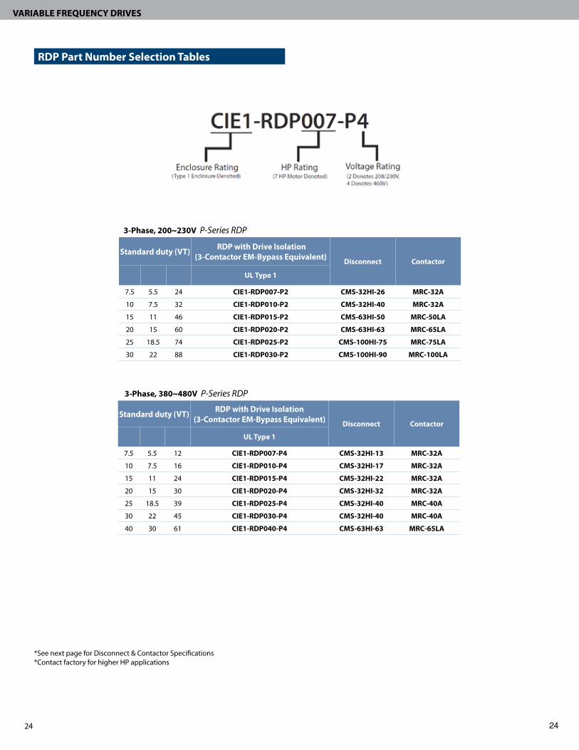
3-Phase, 200~230V P-Series RDP
Standard duty (VT) RDP with Drive Isolation (3-Contactor EM-Bypass Equivalent) Disconnect Contactor
HP kW FLA UL Type 1
7.5 5.5 24 CIE1-RDP007-P2 CMS-32HI-26 MRC-32A
10 7.5 32 CIE1-RDP010-P2 CMS-32HI-40 MRC-32A
15 11 46 CIE1-RDP015-P2 CMS-63HI-50 MRC-50LA
20 15 60 CIE1-RDP020-P2 CMS-63HI-63 MRC-65LA
25 18.5 74 CIE1-RDP025-P2 CMS-100HI-75 MRC-75LA
30 22 88 CIE1-RDP030-P2 CMS-100HI-90 MRC-100LA
3-Phase, 380~480V P-Series RDP
Standard duty (VT) RDP with Drive Isolation (3-Contactor EM-Bypass Equivalent) Disconnect Contactor
HP kW FLA UL Type 1
7.5 5.5 12 CIE1-RDP007-P4 CMS-32HI-13 MRC-32A
10 7.5 16 CIE1-RDP010-P4 CMS-32HI-17 MRC-32A
15 11 24 CIE1-RDP015-P4 CMS-32HI-22 MRC-32A
20 15 30 CIE1-RDP020-P4 CMS-32HI-32 MRC-32A
25 18.5 39 CIE1-RDP025-P4 CMS-32HI-40 MRC-40A
30 22 45 CIE1-RDP030-P4 CMS-32HI-40 MRC-40A
40 30 61 CIE1-RDP040-P4 CMS-63HI-63 MRC-65LA
*See next page for Disconnect & Contactor Specifications*Contact factory for higher HP applications
RDP Part Number Selection Tables

25
VARIABLE FREQUENCY DRIVES
25
P-Drive Wiring Schematic
24

26
VARIABLE FREQUENCY DRIVES
Sensorless vector control � Precise speed control and powerful high torque, up to 150% at 0.5 Hz � Improves control with varying loads � Auto tuning simplifies commissioning � Sensorless mode also selectable
Space Vector Modulation for superior motor life � Super clean sine wave for cool running motors and high efficiency � Minimizes heat losses in for long motor life
Integrated PID
� Precise control to maintain flow-rate, pressure, temperature, etc. without any extra controllers.
� Accepts -10V to 10V analog signals
Operation algorithm � Helps prevent nuisance tripping
Dynamic braking circuit � Minimizes deceleration time on high inertia loads when used with braking resistors.
Built-in RS-485 communication � Remote control and monitoring with other controllers (Modbus standard)
Ground-fault protection � Superior equipment protection
Cooling fan control � Quiet, low noise operation; easy to replace fan module
Compact GS-Series VFD0.5–5HP200~230VAC, 380~480VAC, 3ØCompact Design, Sensorless & VF Control
With sensorless control the GS series makes motor control easy.
The easy to use 4-direction keypad makes settings a snap.

27
VARIABLE FREQUENCY DRIVES
Intuitive multi-direction keypad � User friendly
Optional external keypad for remote control/monitoring � Loader parameters can be downloaded effectively “cloning” inverters for fast set up
in subsequent jobs
Specifications
Output ratingsVoltage (V) Three phase, 200~230V or Three phase, 380~480V
Frequency (Hz) 0~400Hz
Input ratingsVoltage (V) Three phase, 200~230V (+10%, -15%) or Three phase, 380~480V (+10%, -15%)
Frequency (Hz) 50~60Hz (±5%)
Operation
Control method Sensorless Vector, V/F control (Space vector PWM)
Frequency setting resolution Digital reference: 0.01Hz (below 99Hz) & 0.1Hz (100Hz and over); Analog reference: 0.03Hz at 50Hz
Frequency setting accuracy Digital: 0.01% of maximum output frequency; Analog: 0.1% of maximum output frequency
V/F ratio Linear; Square; User V/F
Overload capacity 1 minute at 150%; 30 seconds at 200% (with inverse characteristic proportional to time)
Torque boost Auto; Manual (0~15%)
Assigned terminals FX (forward), RX (reverse), BX (inverter gate blocking), RST (reset), JOG (jog)
Programmable input 8 digital inputs
Analog output 0~10V linear
Input signal
Operator control 4 digit LED display/keypad, Terminals, ModBus communication
Frequency setting Analog: 0~10V, 4~20mA, Digital: Keypad, Communication: ModBus
Start signal Forward, Reverse
Multi-step operation Setting up to 8 speeds (using multi-function terminal)
Multi-step accel./decel. time 0.1~6000 seconds. Maximum 8 pre-defined steps using multi-function terminals
Operational functions DC braking, Frequency limit, Frequency jump, function, Slip compensation, Reverse rotation prevention
Emergency stop stops output from inverter
Jog Jog operation
Fault reset Resets fault signal when protective function is active
Output signalOperational status Frequency detection, Overload alarm, Stall, Overvoltage, Undervoltage, Inverter overheat, Run, Stop, Constant speed,
Speed search, Fault output (relay and open collector output)
Indicator Output frequency, Output current, Output voltage, DC voltage, rpm
Protective functionsTrip Overvoltage, Undervoltage, Overcurrent, Inverter overheat, Motor overheat, I/O phase loss, Overload, Speed command
loss, Hardware fault, Communication error, etc.
Alarm Stall, Overload
Operatingenvironment
Ambient temperature -10°~ 50° C (14°~122° F)
Storage temperature -20°~ 65° C (-4°~149.5° F)
Humidity 95% Relative Humidity maximum (non-condensing)
Altitude & Vibration 1000m max, 5.9m/sec2(0.6g) max.
Application site No corrosive gas, flammable gas, oil mist or dust
Dimensions (H x W x D)
CI-000-GS2/GS4, CI-001-GS2/GS4 5.04” x 2.76” x 5.12” (Height is 6.90” w/ NEMA kit)
CI-002-GS2/GS4 5.04” x 3.94” x 5.12” (Height is 6.90” w/ NEMA kit)
CI-003-GS2/GS4, CI-005-GS2/GS4 5.04” x 5.51” x 6.10” (Height is 6.90” w/ NEMA kit)
Weight (lbs)
CI-000-GS2/GS4, CI-001-GS2/GS4 1.7 lbs
CI-002-GS2/GS4 2.5 lbs
CI-003-GS2/GS4, CI-005-GS2/GS4 4.1 lbs

28
VARIABLE FREQUENCY DRIVES
GS Series Wiring
OptionsDescription Part Number
Remote Keypad Mounting Kit (2 Meter Cable) CI-RKPK-EXT2M-GS
Remote Keypad Mounting Kit (3 Meter Cable) CI-RKPK-EXT3M-GS
Remote Keypad Mounting Kit (5 Meter Cable) CI-RKPK-EXT5M-GS
3-Phase, 200~230V GS - Series VFDHP kW Capacity (kVA) FLA Part Number NEMA 1 Kit 3% Line Reactor*
1/2 0.4 0.95 2.5 CI-000-GS2 CI-NEMA1-GS/A KDRULA54LE01
1 0.75 1.9 5 CI-001-GS2 CI-NEMA1-GS/A KDRULA25LE01
2 1.5 3 8 CI-002-GS2 CI-NEMA1-GS/B KDRULA27LE01
3 2.2 4.5 12 CI-003-GS2 CI-NEMA1-GS/C KDRULA28LE01
5 3.7 6.1 16 CI-005-GS2 CI-NEMA1-GS/C KDRULB22LE01
3-Phase, 380~480V GS - Series VFDHP kW Capacity (kVA) FLA Part Number NEMA 1 Kit 3% Line Reactor*
1/2 0.4 0.95 1.25 CI-000-GS4 CI-NEMA1-GS/A KDRULA6LE01
1 0.75 1.9 2.5 CI-001-GS4 CI-NEMA1-GS/A KDRULA8LE01
2 1.5 3 4 CI-002-GS4 CI-NEMA1-GS/B KDRULA1LE01
3 2.2 4.5 6 CI-003-GS4 CI-NEMA1-GS/C KDRULA2LE01
5 3.7 6.1 8 CI-005-GS4 CI-NEMA1-GS/C KDRULA3LE01
* Line Reactors housed in separate UL Type 1 Enclosure
* Line Reactors housed in separate UL Type 1 Enclosure
*For general reference only, not field wiring. Consult installation instructions.

29
VARIABLE FREQUENCY DRIVES
0.5HP-5HP 200~230VAC, 380~480VAC, 3ØCompact Design, Senserless & VF Control
Enclosed GS-Series VFD
Representative photo only (actual product may vary based on configuration selections)
3-Phase, 200~230V GS-Series Type 12 Enclosed VFDHP kW Capacity (kVA) FLA Base part # 3% Line Reactor*
1/2 0.4 0.95 2.5 CIE12-ED000-GS2 VFD-KDRA54L
1 0.75 1.9 5 CIE12-ED001-GS2 VFD-KDRA25L
2 1.5 3 8 CIE12-ED002-GS2 VFD-KDRA27L
3 2.2 4.5 12 CIE12-ED003-GS2 VFD-KDRA28L
5 3.7 6.1 16 CIE12-ED005-GS2 VFD-KDRA22L
3-Phase, 380~480V GS-Series Type 12 Enclosed VFDHP kW Capacity (kVA) FLA Base part # 3% Line Reactor*
1/2 0.4 0.95 1.25 CIE12-ED000-GS4 VFD-KDRA6L
1 0.75 1.9 2.5 CIE12-ED001-GS4 VFD-KDRA8L
2 1.5 3 4 CIE12-ED002-GS4 VFD-KDRA1L
3 2.2 4.5 6 CIE12-ED003-GS4 VFD-KDRA2L
5 3.7 6.1 8 CIE12-ED005-GS4 VFD-KDRA3L
OptionsPart Number Description
VFD-RPL* Run Pilot Light (Green Standard)
VFD-FLT* Fault Pilot Light (Red Standard)
VFD-OFF* Off Pilot Light (Red Standard)
VFD-HOA Hand/Off/Auto switch
VFD-SPD Door Mounted Speed Potentiometer
VFD-LTA Lightning Arrestor
VFD-KPD Door Mounted Keypad
VFD-KPD/4X Door Mounted Keypad with Type 4X Cover
* Select 24V or 120V based on package control voltage. For UL Type 1 select 24V. For UL Type 3R & 12 select 120V.
3-Phase, 200~230V GS-Series 3R Enclosed VFDHP kW Capacity (kVA) FLA Base part # 3% Line Reactor*
1/2 0.4 0.95 2.5 CIE3R-ED000-GS2 VFD-KDRA54L
1 0.75 1.9 5 CIE3R-ED001-GS2 VFD-KDRA25L
2 1.5 3 8 CIE3R-ED002-GS2 VFD-KDRA27L
3 2.2 4.5 12 CIE3R-ED003-GS2 VFD-KDRA28L
5 3.7 6.1 16 CIE3R-ED005-GS2 VFD-KDRA22L
3-Phase, 380~480V GS-Series 3R Enclosed VFDHP kW Capacity (kVA) FLA Base part # 3% Line Reactor*
1/2 0.4 0.95 1.25 CIE3R-ED000-GS4 VFD-KDRA6L
1 0.75 1.9 2.5 CIE3R-ED001-GS4 VFD-KDRA8L
2 1.5 3 4 CIE3R-ED002-GS4 VFD-KDRA1L
3 2.2 4.5 6 CIE3R-ED003-GS4 VFD-KDRA2L
5 3.7 6.1 8 CIE3R-ED005-GS4 VFD-KDRA3L

30
VARIABLE FREQUENCY DRIVES
Standard HVAC bypass features � HAND/OFF/AUTO � Fireman’s override/smoke purge ready � 2 contactor with manual motor starter
disconnect version � UL 508C rating with all drive models for
maximum motor protection
Wide range of design options � Door mounted controls, speed pot, HOA, &
pilot lights � Input or output drive reactors � Electronic overload with full phase
protection on bypass
Fully enclosed drives for any environment � We offer any enclosure type and NEMA
ratings (Stainless, fiberglass, watertight, etc.) � Dust tight type 12 enclosures include ducting
and ventilation for maximum cooling
Applications � Supply and return fans � Performance contracting � Building Automation
GS-Series Bypass0.5–5HP200~230VAC, 380~480VAC, 3ØSpace Vector Pulse Width Modulation
Interior Bypass Photo

31
VARIABLE FREQUENCY DRIVES
3-Phase, 230V GS-Series VFD Bypass
HP FLABypass with Drive Isolation (3-Contactor) 2-Contactor Bypass Configuration
UL Type 1 UL Type 3R UL Type 12 UL Type 1 UL Type 3R UL Type 12
1/2 2.5 CIE1-BYP000-GS2/3 CIE3R-BYP000-GS2/3 CIE12-BYP000-GS2/3 CIE1-BYP000-GS2 CIE3R-BYP000-GS2 CIE12-BYP000-GS2
1 5 CIE1-BYP001-GS2/3 CIE3R-BYP001-GS2/3 CIE12-BYP001-GS2/3 CIE1-BYP001-GS2 CIE3R-BYP001-GS2 CIE12-BYP001-GS2
2 8 CIE1-BYP002-GS2/3 CIE3R-BYP002-GS2/3 CIE12-BYP002-GS2/3 CIE1-BYP002-GS2 CIE3R-BYP002-GS2 CIE12-BYP002-GS2
3 12 CIE1-BYP003-GS2/3 CIE3R-BYP003-GS2/3 CIE12-BYP003-GS2/3 CIE1-BYP003-GS2 CIE3R-BYP003-GS2 CIE12-BYP003-GS2
5 16 CIE1-BYP005-GS2/3 CIE3R-BYP005-GS2/3 CIE12-BYP005-GS2/3 CIE1-BYP005-GS2 CIE3R-BYP005-GS2 CIE12-BYP005-GS2
OptionsPart Number Description
VFD-RPL* Run Pilot Light (Green Standard)
VFD-BPL* Bypass Pilot Light (Amber Standard)
VFD-FLT* Fault Pilot Light (Red Standard)
VFD-OFF* Off Pilot Light (Red Standard)
VFD-SPD Door Mounted Speed Potentiometer
VFD-LTA Lightning Arrestor
VFD-KPD Door Mounted Keypad
VFD-KPD/4X Door Mounted Keypad with Type 4X Cover
230V Line Reactor OptionsHP Part Number
1/2 VFD-KDRA54L
1 VFD-KDRA25L
2 VFD-KDRA27L
3 VFD-KDRA28L
5 VFD-KDRA22L
460V Line Reactor OptionsHP Part Number
1/2 VFD-KDRA6L
1 VFD-KDRA8L
2 VFD-KDRA1L
3 VFD-KDRA2L
5 VFD-KDRA3L
3-Phase, 460V GS-Series VFD Bypass
HP FLABypass with Drive Isolation (3-Contactor) 2-Contactor Bypass Configuration
UL Type 1 UL Type 3R UL Type 12 UL Type 1 UL Type 3R UL Type 12
1/2 1.25 CIE1-BYP000-GS4/3 CIE3R-BYP000-GS4/3 CIE12-BYP000-GS4/3 CIE1-BYP000-GS4 CIE3R-BYP000-GS4 CIE12-BYP000-GS4
1 2.5 CIE1-BYP001-GS4/3 CIE3R-BYP001-GS4/3 CIE12-BYP001-GS4/3 CIE1-BYP001-GS4 CIE3R-BYP001-GS4 CIE12-BYP001-GS4
2 4 CIE1-BYP002-GS4/3 CIE3R-BYP002-GS4/3 CIE12-BYP002-GS4/3 CIE1-BYP002-GS4 CIE3R-BYP002-GS4 CIE12-BYP002-GS4
3 6 CIE1-BYP003-GS4/3 CIE3R-BYP003-GS4/3 CIE12-BYP003-GS4/3 CIE1-BYP003-GS4 CIE3R-BYP003-GS4 CIE12-BYP003-GS4
5 8 CIE1-BYP005-GS4/3 CIE3R-BYP005-GS4/3 CIE12-BYP005-GS4/3 CIE1-BYP005-GS4 CIE3R-BYP005-GS4 CIE12-BYP005-GS4
* Select 24V or 120V based on package control voltage. For UL Type 1 select 24V. For UL Type 3R & 12 select 120V.
Type 1 Indoor Type 3R Rain Resistant

32
COOLING TOWER PANEL
Integrates with an existing automation system or temperature control option for standalone application
� Scalable options to meet any application � Adequately sized to add other options including spray pump, basin
heater control, line reactors, and other critical features.
Cerus P-Series HVAC drive for optimum performance � Space-vector control for clean sinewave output for efficiency and
enhanced motor life � Automatic energy savings mode � Dual PID controls. Primary for maintaining temperature, pressure, etc.,
additional for secondary PID control of external device. � 32 character LCD for easy set up and parameter display. � Standard kWh metering of energy usage to optimize control
Multiple PID set points � Programmable and selectable for maintaining pressure or temperature during
different seasons or operating conditions
Integrated HOA and 3-Contactor Bypass Standard
� Integrated HOA and status indications for simplified operation
� VFD isolating three contactor bypass with disconnect options standard
All inclusive single point cooling tower control
Stand Alone or Slave Operation OptionsScalable to meet any application Cerus Energy Saving VFDs
TOWER IQ
“Having the ability to retrofit existing installations with a stand-alone capable panel gives us immediate energy savings--regardless of the type of energy management system.”
Smart Design
BACnet® is a registered trademark of ASHRAE.

33
VARIABLE FREQUENCY DRIVES
Additional Options
Basin Heater ControlPrevents freezing Contactor activated by external signal (i.e.thermostat).Provision for low water protection
Spray Pump StarterFull voltage starter with overload relayHOA switch providedStatus indication options
2-stage Temperature ControlStart/stop sequencing for fans, dampers, and spray pumpsProvides analog output to vary speed of drive Accepts direct input from RTD type sensor or thermocoupleAdjustments for set-points and hysteresis
Panel Space HeaterTo prevent condensation and freezing
Line ReactorsFor use in systems with unstable utility power, long leads from service transformer to VFD and/or when power source is greater than 10 times the kVA rating of the inverterProvides harmonic distortion filtering
Vibration cut-outProvision for vibration switch cut-out
Water Level Control PowerProvides 120VAC @ 2A
86.5
Output Reactor/FiltersUse when leads from drive to motor exceed 35’ at 480VAC or greater.Above 100’ use output filterDecreases level of voltage spikes to prevent motor insulation breakdown.
Single source control reduces components, increases reliability � Wide range of options available. � One connection point for power
Temperature control option provides complete stand alone operation. � Ideal for retrofit � Start/stop sequencing for fans, dampers, and spray pumps � Provides analog output to vary speed of drive � Accepts direct input from RTD type sensor or thermocouple � Adjustments for set-points and hysteresis

34
COOLING TOWER PANEL
Tower IQ SpecificationsProtective Functions
Alarm Alarm Stall, Overload, Temperature sensor fault
TripOvervoltage, Undervoltage, Overcurrent, Inverter overheat, Motor overheat, I/O phase loss, Fuse open, Ground fault, External fault 1, 2, Option fault, Overload, Speed command loss, Hardware fault, Communication error, etc.
Input / Output Voltage 3 phase 200 – 230V (-15%,+10%) 50 -60Hz, 3 phase 480V (-15%,+10%) 50 -60Hz
Power Rating 7.5 HP to 400 HP
Efficiency > 95%
Control Input 0-10 VDC, 4-20 mA, keypad, or digital input from communication card
Communication Options BACnet, Modbus, LonWorks, N2, or RS485
Environmental Package: UL Type 3R for outdoor or UL Type 12: Ambient temperature up to 110ºF; UL type indoor humidity up to 95% RH non-condensing. Drive: Ambient temperature up to 122ºF
Programmable I/O 8 digital inputs, 4 digital outputs, 2 analog outputs
Options
Spray Pump Starter 1 hp to 20 hp (output voltage matches panel main voltage)
Basin Heater 4 kW to 25 kW (output voltage matches panel main voltage)
De-Icer Digital input for fan reverse

35
VARIABLE FREQUENCY DRIVES
Ordering and Sizing Information
Cooling Tower Options Basin Heater Contactor & Spray Pump StarterBasin Heater Contactor Spray Pump Starter
kW Max Amps Basin Heater
3 Phase HPSpray Pump
208V 230V 480V 208V 230V 460V3/4 3/4 2 2.5 CTP-9/HI-2.5 1/2 1/2 1 CTP-9/H-2.5
1 1.5 3 4.0 CTP-9/HI-4 3/4 3/4 2 CTP-9/H-4
2 2 4 6.0 CTP-9/HI-6 1 1.5 3 CTP-9/H-6
2.5 3 6 8.0 CTP-9/HI-8 2 2 5 CTP-9/H-8
3 3.5 8 10.0 CTP-18/HI-10 2 3 5 CTP-18/H-10
4 5 10 13.0 CTP-18/HI-13 3 3 7.5 CTP-18/H-13
6 6.5 14 17.0 CTP-18/HI-17 3 5 10 CTP-18/H-17
7.5 8.5 18 22.0 CTP-32/HI-22 5 7.5 15 CTP-32/H-22
9 10 21 26.0 CTP-32/HI-26 7.5 7.5 15 CTP-32/H-26
11 12 26 32.0 CTP-32/HI-32 7.5 10 20 CTP-32/H-32
3-Phase, 200~230V Cooling Tower ControlHP FLA UL Type 1 UL Type 3R 3% Line Reactor
5 24 CTP1-BYP005-P2 CTP3R-BYP005-P2 VFD-KDRB22L
7.5 24 CTP1-BYP007-P2 CTP3R-BYP007-P2 VFD-KDRB23L
10 32 CTP1-BYP010-P2 CTP3R-BYP010-P2 VFD-KDRD25L
15 46 CTP1-BYP015-P2 CTP3R-BYP015-P2 VFD-KDRD24L
20 60 CTP1-BYP020-P2 CTP3R-BYP020-P2 VFD-KDRD26L
25 74 CTP1-BYP025-P2 CTP3R-BYP025-P2 VFD-KDRC22L
30 88 CTP1-BYP030-P2 CTP3R-BYP030-P2 VFD-KDRF24L
40 115 CTP1-BYP040-P2 CTP3R-BYP040-P2 VFD-KDRF25L
3-Phase, 380~480V Cooling Tower ControlHP FLA UL Type 1 UL Type 3R 3% Line Reactor Output Reactor Output Filter
5 12 CTP1-BYP005-P4 CTP3R-BYP005-P4 VFD-KDRA3L VFD-KDRA3P VFD-V1K8A00
7.5 12 CTP1-BYP007-P4 CTP3R-BYP007-P4 VFD-KDRA4L VFD-KDRA4P VFD-V1K12A00
10 16 CTP1-BYP010-P4 CTP3R-BYP010-P4 VFD-KDRA5L VFD-KDRB1P VFD-V1K18A00
15 24 CTP1-BYP015-P4 CTP3R-BYP015-P4 VFD-KDRB2L VFD-KDRD1P VFD-V1K21A00
20 30 CTP1-BYP020-P4 CTP3R-BYP020-P4 VFD-KDRB1L VFD-KDRD2P VFD-V1K27A00
25 39 CTP1-BYP025-P4 CTP3R-BYP025-P4 VFD-KDRD1L VFD-KDRD3P VFD-V1K35A00
30 45 CTP1-BYP030-P4 CTP3R-BYP030-P4 VFD-KDRD2L VFD-KDRD4P VFD-V1K45A00
40 61 CTP1-BYP040-P4 CTP3R-BYP040-P4 VFD-KDRC1L VFD-KDRC1P VFD-V1K55A00
50 75 CTP1-BYP050-P4 CTP3R-BYP050-P4 VFD-KDRF2L VFD-KDRF1P VFD-V1K80A00
60 91 CTP1-BYP060-P4 CTP3R-BYP060-P4 VFD-KDRF4L VFD-KDRF2P VFD-V1K80A00
75 110 CTP1-BYP075-P4 CTP3R-BYP075-P4 VFD-KDRF3L VFD-KDRF3P VFD-V1K110A00
100 152 CTP1-BYP0100-P4 CTP3R-BYP100-P4 VFD-KDRH3L VFD-KDRH1P VFD-V1K130A00
125 183 CTP1-BYP0125-P4 CTP3R-BYP125-P4 VFD-KDRH2L VFD-KDRI1P VFD-V1K160A00
OptionsPart Number Description
VFD-RPL* Run Pilot Light (Green Standard)
VFD-BPL* Bypass Pilot Light (Amber Standard)
VFD-FLT* Fault Pilot Light (Red Standard)
VFD-OFF* Off Pilot Light (Red Standard)
CTP-TC Temperature Controller
CTP-60HTR 60W Panel Space Heater
CTP-250HTR 250W Panel Space Heater
* Select 24V or 120V based on package control voltage. For UL Type 1 select 24V. For UL Type 3R & 12 select 120V.

ENCLOSED DRIVES FOR ANY ENVIRONMENT
Wide range of design options � Door mounted controls, speed pot, HOA, &
pilot lights � Input or output drive reactors � Electronic overload with full phase
protection on bypass
Fully enclosed drives for any environment � We offer any enclosure type and NEMA
ratings (Stainless, fiberglass, watertight, etc.) � Dust tight type 12 enclosures include ducting
and ventilation for maximum cooling
Cerus also offers bypass assemblies for any environment

We offer engineered solutions for our starter and VFD products to suit your specific application requirement. Modifications include a full range of enclosure options capable of withstanding almost any environment, complex multi-motor control, or simply ensuring the controls follow a specific sequence of operations. We respond, often times with same day quotes depending on application complexity and job requirements.
Redundant Drive Configuration
With a Redundant Drive Package you have a backup � Easy set up thanks to 32 character LCD & simplified parameters � Maximum Energy Savings with space vector control � Versatile features for demanding applications, built in multi-motor control
(for up to 4 additional motors) � Torque boost and speed search features offer smooth motor starts

38
VARIABLE FREQUENCY DRIVES
P Series Dimensions *ALL MEASUREMENTS IN INCHES
*ALL MEASUREMENTS IN INCHES
GS Series Dimensions
5.91”
6.17”
A
C
B
P-Series Drive H x W x D, (A x B x C)
CI-007-P211.19”x 5.91” x 6.17”
CI-007-P4
CI-010-P2
11.18” x 7.87” x 7.16”CI-010-P4
CI-015-P2
CI-015-P4
CI-020-P2
15.16” x 9.84” x 7.94”CI-020-P4
CI-025-P2
CI-025-P4
CI-030-P2
18.11” x 11.97” x 9.22”CI-030-P4
CI-040-P2
CI-040-P4
CI-050-P420.28” x 11.81” x 10.46”
CI-060-P4
CI-075-P4 20.28” x 11.81” x 11.52”
CI-100-P423.09” x 14.57” x 13.29”
CI-125-P4
CI-150-P430.26” x 20.80” x 16.64”
CI-200-P4
CI-250-P4 33.23” x 20.80” x 16.64”
CI-350-P441.85” x 21.17” x 17.70”
CI-400-P4
CI-500-P4 43.7” x 30.8” x 17.4”
CI-600-P451.3” x 36.3” x 19.5”
CI-700-P4
GS-Series Drive H x W x D, (A x B x C)
CI-000-GS2
5.04”x 2.76”x 5.12”(H = 6.90” w/NEMA kit)
CI-000-GS4
CI-001-GS2
CI-001-GS4
CI-002-GS2 5.04”x 3.94”x 5.12”(H = 6.90” w/NEMA kit)CI-002-GS4
CI-003-GS2
5.04”x 5.51”x 6.10”(H = 6.90” w/NEMA kit)
CI-003-GS4
CI-005-GS2
CI-005-GS4

39
VARIABLE FREQUENCY DRIVES
P-Series UL Type 1 Bypass Dimensions
GS Series UL Type 1 Bypass Dimensions
*ALL MEASUREMENTS IN INCHES
*ALL MEASUREMENTS IN INCHES
UL Type 1 P-Drive Bypass H x W x D (A x B x C)
CIE1-BYP001-P4 ~ CIE1-BYP015-P4/3
CIE1-BYP001-P2 ~CIE1-BYP010-P2/3
38.00”x 8.00” x 8.12”
CIE1-BYP020-P4 ~ CIE1-BYP025-P4/3
CIE1-BYP015-P2 ~CIE1-BYP020-P2/3
50.12” x 9.97” x 8.70”
CIE1-BYP030-P4 ~ CIE1-BYP040-P4/3
CIE1-BYP025-P2 ~CIE1-BYP030-P2/3
56.89” x 12.17” x 9.97”
UL Type 1 GS-Drive Bypass H x W x D (A x B x C)
CIE1-BYP000-GS2 ~CIE1-BYP005-GS2
38.00”x 8.00” x 8.12” CIE1-BYP000-GS4 ~CIE1-BYP005-GS4
* Contact Cerus or visit www.Cerusind.com for larger bypass dimensions
A
B C
B
C
A

40
VARIABLE FREQUENCY DRIVES
EMB UL Type 1 Bypass Dimensions *ALL MEASUREMENTS IN INCHES
UL Type 1 P-Drive EMBass H x W x D (A x B x C)
CIE1-EMB001-P2/3 ~CIE1-EMB007-P2/3
43 3/4”x 8” x 9 3/4” CIE1-EMB001-P4/3 ~CIE1-EMB015-P4/3
CIE1-EMB010-P2/3 ~CIE1-EMB020-P2/3
50 3/16” x 10” x 10”CIE1-EMB020-P4/3 ~ CIE1-EMB025-P4/3
CIE1-EMB025-P2 ~CIE1-EMB030-P2/3
56 5/16” x 12 3/16” x 11 5/16”CIE1-EMB030-P4 ~ CIE1-EMB040-P4/3
* Contact Cerus or visit www.Cerusind.com for larger bypass dimensions and mounting dimensions
A
UL Type 3R P-Drive EMBass H x W x D (A x B x C)
CIE3R-EMB001-P2 ~CIE3R-EMB007-P2/3
35” x 24” x 12”CIE3R-EMB001-P4 ~ CIE3R-EMB015-P4/3
CIE3R-EMB010-P2 ~ CIE3R-EMB015-P2/3 41” x 24” x 12”
CIE3R-EMB020-P2 ~CIE3R-EMB020-P2/3
47” x 24” x 14”CIE3R-EMB020-P4 ~CIE3R-EMB025-P4/3
CIE3R-EMB025-P2 ~ CIE3R-EMB030-P2/3
56” x 36” x 16”CIE3R-EMB030-P4 ~ CIE3R-EMB040-P4/3
*ALL MEASUREMENTS IN INCHES
EMB UL Type 3R Bypass Dimensions
* Contact Cerus or visit www.Cerusind.com for larger bypass dimensions and mounting dimensions

41
VARIABLE FREQUENCY DRIVES
P-Series UL Type 1 RDP Dimensions *ALL MEASUREMENTS IN INCHES
UL Type 1 RDP H x W x D (A x B x C)
CIE1-RDP001-P2 ~CIE1-RDP007-P2
40 3/4”x 18” x 10 3/32” CIE1-RDP001-P4 ~CIE1-RDP015-P4
CIE1-RDP010-P2 ~CIE1-RDP020-P2
49 7/8” x 22” x 10 19/32”CIE1-RDP020-P4 ~ CIE1-RDP025-P4
CIE1-RDP025-P2 ~CIE1-RDP030-P2
57 7/8” x 26” x 11 25/32”CIE1-RDP030-P4 ~ CIE1-RDP040-P4
42
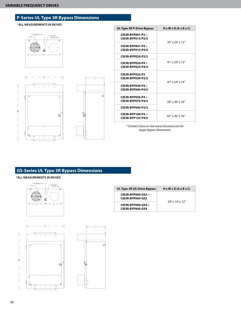
VARIABLE FREQUENCY DRIVES
A
A
UL Type 3R GS-Drive Bypass H x W x D (A x B x C)
CIE3R-BYP000-GS2 ~CIE3R-BYP005-GS2
29” x 14” x 12”CIE3R-BYP000-GS4 ~CIE3R-BYP005-GS4
UL Type 3R P-Drive Bypass H x W x D (A x B x C)
CIE3R-BYP001-P2 ~CIE3R-BYP015-P2/3
35” x 24” x 12”CIE3R-BYP001-P4 ~ CIE3R-BYP015-P4/3
CIE3R-BYP020-P2/3
41” x 24” x 12”CIE3R-BYP020-P4 ~ CIE3R-BYP025-P4/3
CIE3R-BYP025-P2CIE3R-BYP030-P2/3
47” x 24” x 14”CIE3R-BYP030-P4 ~CIE3R-BYP040-P4/3
CIE3R-BYP050-P4 ~CIE3R-BYP075-P4/3 56” x 36” x 16”
CIE3R-BYP040-P2/3
CIE3R-BYP100-P4 ~CIE3R-BYP125-P4/3 67” x 36” x 16”
*ALL MEASUREMENTS IN INCHES
*ALL MEASUREMENTS IN INCHES
P-Series UL Type 3R Bypass Dimensions
GS-Series UL Type 3R Bypass Dimensions
* Contact Cerus or visit www.Cerusind.com for larger bypass dimensions

43
VARIABLE FREQUENCY DRIVES
12 GS-Series Enclosed Drive H x W x D, (A x B x C)
ALL GS NEMA 12 Enclosures 16”x 14”x 8”
12 P-Series Enclosed Drive H x W x D, (A x B x C)
CIE12-ED007-P2/P424”x 20”x 8”
CIE12-ED010-P2/P4
CIE12-ED015-P2/P430”x 24”x 12”
CIE12-ED020-P2/P4
CIE12-ED025-P2/P4
36”x 24”x 12”CIE12-ED030-P2/P4
CIE12-ED040-P2/P4
CIE12-ED050-P4
36”x 30”x 16”CIE12-ED060-P4
CIE12-ED075-P4
CIE12-ED100-P442”x 30”x 16”
CIE12-ED125-P4
CIE12-ED150-P460”x 36”x 20”
CIE12-ED200-P4
CIE12-ED250-P4 60”x 60”x 24”
CIE12-ED350-P472”x 60”x 24”
CIE12-ED400-P4
*ALL MEASUREMENTS IN INCHES
*ALL MEASUREMENTS IN INCHES
P-Series UL Type 12 Enclosed Dimensions
GS-Series UL Type 12 Enclosed Dimensions
A
B C
A
B C

44
VARIABLE FREQUENCY DRIVES
3R P-Series Enclosed Drive H x W x D, (A x B x C)
CIE3R-ED001-P2/P4 ~CIE3R-ED015-P2/P4 29”x24”x12”
CIE3R-ED020-P2/P4 ~CIE3R-ED025-P2/P4 35”x24”x12”
CIE3R-ED030-P2/P4CIE3R-ED040-P2/P4 42”x24”x12’
CIE3R-ED050-P4 ~CIE3R-ED075-P4 47”x24”x14”
CIE3R-ED100-P456”x36”x16”
CIE3R-ED125-P4
A
A
*ALL MEASUREMENTS IN INCHES
*ALL MEASUREMENTS IN INCHES
P-Series UL Type 3R Enclosed Dimensions
GS-Series UL Type 3R Enclosed Dimensions
3R GS-Series Enclosed Drive H x W x D, (A x B x C) ALL GS NEMA 3R Enclosures 22”x15”x8”
* Contact Cerus or visit www.Cerusind.com for larger enclosed VFD dimensions

45
VARIABLE FREQUENCY DRIVES
A
*ALL MEASUREMENTS IN INCHES
Cooling Tower Panel Dimensions
Tower IQ H x W x D, (A x B x C)
CTP-BYP001-P2/4 ~CTP-BYP010-P2/4 35” x 24” x 12”
CTP-BYP015-P2
41” x 24” x 12”CTP-BYP015-P4 ~CTP-BYP020-P4
CTP-BYP020-P2 ~CTP-BYP025-P2
47” x 24” x 14”CTP-BYP025-P4 ~CTP-BYP030-P4
CTP-BYP030-P2 ~CTP-BYP040-P2
56” x 36” x 16”CTP-BYP040-P4 ~CTP-BYP060-P4
CTP-BYP075-P4 ~CTP-BYP100-P4 67” x 36” x 16”

46
VARIABLE FREQUENCY DRIVES
Features � Reduces input line distortion � Eliminates transient and overvoltage
nuisance tripping � Provides excellent harmonic
mitigation without adding capacitance
� Improve true power factor � Helps to prevent VFD
component damage
Optimized Line Reactors (200~230V) 3%
HP Open Chassis
UL Type 1 Enclosed
1/2 KDRA54L KDRULA54LE01 3/4 KDRA53L KDRULA53LE01
1 KDRA25L KDRULA25LE01 1.5 KDRA26L KDRULA26LE01 2 KDRA27L KDRULA27LE01 3 KDRA28L KDRULA28LE01 5 KDRB22L KDRULB22LE01
7.5 KDRB23L KDRULB23LE01 10 KDRD25L KDRULD25LE01 15 KDRD24L KDRULD24LE01 20 KDRD26L KDRULD26LE01 25 KDRC22L KDRULC22LE01 30 KDRF24L KDRULF24LE01 40 KDRF25L KDRULF25LE01
5%
OpenChassis
UL Type 1 Enclosed
KDRA54H KDRULA54HE01 KDRA53H KDRULA53HE01 KDRA25H KDRULA25HE01 KDRA27H KDRULA27HE01 KDRA26H KDRULA26HE01 KDRA28H KDRULA28HE01 KDRB25H KDRULB25HE01 KDRB26H KDRULB26HE01 KDRD21H KDRULD21HE01 KDRD22H KDRULD22HE01 KDRC22H KDRULC22HE01 KDRF28H KDRULF28HE01 KDRF25H KDRULF25HE01 KDRF26H KDRULF26HE01
Optimized Line Reactors (380~480V) 3%
HP Open Chassis
UL Type 1 Enclosed
1/2 KDRA6L KDRULA6LE013/4 KDRA7L KDRULA7LE01
1 KDRA8L KDRULA8LE011.5 KDRA9L KDRULA9LE012 KDRA1L KDRULA1LE013 KDRA2L KDRULA2LE015 KDRA3L KDRULA3LE01
7.5 KDRA4L KDRULA4LE0110 KDRA5L KDRULA5LE0115 KDRB2L KDRULB2LE0120 KDRB1L KDRULB1LE0125 KDRD1L KDRULD1LE0130 KDRD2L KDRULD2LE0140 KDRC1L KDRULC1LE0150 KDRF2L KDRULF2LE0160 KDRF4L KDRULF4LE0175 KDRF3L KDRULF3LE01
100 KDRH3L KDRULH3LE01125 KDRH2L KDRULH2LE01150 KDRH1L KDRULH1LE01200 KDRG3L KDRULG3LE01250 KDRG1L KDRULG1LE01300 KDRG2L KDRULG2LE01350 KDRJ2L KDRULJ2LE01400 KDRJ1L KDRULJ1LE01
5%Open
ChassisUL Type 1 Enclosed
KDRA6H KDRULA6HE01KDRA7H KDRULA7HE01KDRA8H KDRULA8HE01KDRA9H KDRULA9HE01KDRA1H KDRULA1HE01KDRA2H KDRULA2HE01KDRA3H KDRULA3HE01KDRA4H KDRULA4HE01KDRA5H KDRULA5HE01KDRB2H KDRULB2HE01KDRC3H KDRULC3HE01KDRC1H KDRULC1HE01KDRE2H KDRULE2HE01KDRF4H KDRULF4HE01KDRF1H KDRULF1HE01KDRF2H KDRULF2HE01KDRH2H KDRULH2HE01KDRH1H KDRULH1HE01KDRG3H KDRULG3HE01KDRG1H KDRULG1HE01KDRJ1H KDRULJ1HE01KDRL1H KDRULL1HE01KDRL2H KDRULL2HE01KDRL3H KDRULL3HE01KDRL4H KDRULL4HE01
Specifications � Maximum current: 100kA � Maximum energy: 3000J � Unlimited number of surges � Response times to clamp:
- 1 mA test: 5 ns - 10kA: 10 ns - 50kA: 25 ns
Industrial Surge ArrestorsDescription Part Number
3-Wire 1Ø 0~250V LA-302
4-wire 3Ø 0~600V LA-603
Optimized Line Reactors3 Phase, 600V Class UL & CE Marked Open Chassis & UL Type 1

47
VARIABLE FREQUENCY DRIVES
Optimized dV/dT Output FilterHorsepower
Open Chassis UL Type 1Enclosed 240V 480V
- 3/4 V1K2A00 V1K2A011/2 1-1.5 V1K3A00 V1K3A013/4 2 V1K4A00 V1K4A01
1-1.5 3 V1K6A00 V1K6A012 5 V1K8A00 V1K8A013 7.5 V1K12A00 V1K12A015 10 V1K16A00 V1K16A01- 10 V1K18A00 V1K18A01- 15 V1K21A00 V1K21A01
7.5 15 V1K25A00 V1K25A01- 20 V1K27A00 V1K27A01
10 25 V1K35A00 V1K35A0115 30 V1K45A00 V1K45A0120 40 V1K55A00 V1K55A01
25-30 50 - 60 V1K80A00 V1K80A0140 75 V1K110A00 V1K110A01- 100 V1K130A00 V1K130A01- 125 V1K160A00 V1K160A01- 150 V1K200A00 V1K200A01- 200 V1K250A00 V1K250A01- 250 V1K305A00 V1K305A01- 300 V1K362A00 V1K362A01- 350 V1K420A00 V1K420A01- 400 V1K480A00 V1K480A01
Optimized Output ReactorsHorsepower
Open Chassis UL Type 1Enclosed240V 480V
3/4 2 KDRA1P KDRULA1PE011 3 KDRA2P KDRULA2PE012 5 KDRA3P KDRULA3PE013 7.5 KDRA4P KDRULA4PE01- 10 KDRB1P KDRULB1PE015 15 KDRD1P KDRULD1PE01
7.5 20 KDRD2P KDRULD2PE0110 25 KDRD3P KDRULD3PE01- 30 KDRD4P KDRULD4PE01
15 40 KDRC1P KDRULC1PE0120 50 KDRF1P KDRULF1PE0125 60 KDRF2P KDRULF2PE0130 75 KDRF3P KDRULF3PE0140 100 KDRH1P KDRULH1PE01- 125 KDRI1P KDRULI1PE01- 150 KDRI2P KDRULI2PE01- 200 KDRG1P KDRULG1PE01- 250 KDRJ1P KDRULJ1PE01- 300 KDRJ2P KDRULJ2PE01- 350 KDRL1P KDRULL1PE01- 400 KDRL2P KDRULL2PE01
Output Reactors � Protection for motor leads between 50 - 100 ft � Protects VFD output by dampening peak
voltage overshoot � Extends motor life by reducing heat and
audible noise � Helps prevent VFD instantaneous
overcurrent trips
Drive Output Reactors & Filters3 Phase, 600V Class UL & CE Marked UL Type 1 & 3R Available
dV/dT Output Filters � Protection for motor leads exceeding 100 ft � Ensures smooth VFD sinusoidal output to motor � Extends motor life by reducing heat, audible
noise and insulation breakdown � Reduces “reflective wave” effect by limiting peak
voltage and rise time � Helps prevent VFD
instantaneous overcurrent trips

48
VARIABLE FREQUENCY DRIVES
Engineered for Superior Accuracy & Performance � ±0.5% overall full scale at room temperature � ±1% overall full scale over -40°C to 105°C for 75 PSI to 200 PSI � Includes repeatability, hysteresis and linearity � Custom ASIC provides signal conditioning for calibration and
temperature compensation � Optional electrical connectors available (Packard, Deutsch, Mini DIN,
M12, Integral Harness)
Solid Construction � Laser-welded stainless steel design for optimal media isolation � Withstands up to three times full scale burst pressure � Reverse voltage protected
Accurate, Reliable & VersatileCerus pressure sensors are ideal for industrial and commercial applications where measurement and performance are critical. Additionally, these micro-machined sensors are compact in size, constructed of rugged materials designed to meet the highest standards of chemical compatibility.
Gage Pressure Sensors0-5VDC Output 4-20mA Output
Pressure Range Part Number Part Number
0-15 PSIG PG-15SB PG-15SC
0-25 PSIG PG-25SB PG-25SC
0-50 PSIG PG-50SB PG-50SC
0-75 PSIG PG-75SB PG-75SC
0-100 PSIG PG-100SB PG-100SC
0-250 PSIG PG-250SB PG-250SC
0-300 PSIG PG-300SB PG-300SC
0-500 PSIG PG-500SB PG-500SC
Gage Pressure Sensors0~500 PSIG ModelsStainless Steel Construction 36” Wire Leads, 1/4”-18 NPT

49
VARIABLE FREQUENCY DRIVES
� Intrinsic flow measurement results in optimal performance � No gravity effect allows mounting in any position � LCD display for easy setup and commissioning � Switch-selectable pressure ranges � Applications include static pressure measurement, variable
air volume system control and monitoring filter status
Specifications
Power Supply 12-30VDC/24VAC, 30mA maximum (13VDC min for 10V full scale output)
Output Type Dual, 4-20mA & 0-5/10VDC (3-wire)
Output Scaling0-1” (Selectable 0.1, 0.5, 1.0) uni or bi-directional
0-2” (Selectable 0.5, 1”, 2”) uni or bi-directional
Calibrated Temperature Range 32° to 122°F (0-50°C)
Media compatibility Dry, oil-free air, N2
Sensor Type Digital CMOS intrinsic flow differential pressure
Performance
Position EffectsNone - position insensitive
Zero drift
Zero point Accuracy 0.5 Pa
Span Accuracy 3% of reading
Zero point repeatability 0.1 Pa
Span repeatability 0.5% of reading
Temp offset None (less than resolution)
Temp span shift < 0.5% of reading per 10°C
Selectable Ranges, Outputs and Stable Dry Media Operation
� Zero drift technology ensures precision measurement � LCD display for easy setup and commissioning � Auto zero pushbutton input and auto zero control
contact for system accuracy � Applications include duct pressure monitoring and
air-flow stations
Specifications
Power Supply 12-30VDC/24VAC, 30mA maximum (13VDC min for 10V full scale output)
Output Type Dual, 4-20mA & 0-5/10VDC (3-wire)
Output Scaling0-10” (Selectable 2.5, 5, 10"WC)0-25” (Selectable 10, 15, 25"WC)
Calibrated Temperature Range 50° to 140°F (10-60°C)
Media Dry, oil-free air, N2Sensor Type Integrated, micro machined silicon piezoresistivePerformance
Accuracy (Linearity, hysteresis,
temperature)2.5% full scale
Auto-zero input Pushbutton and contact closure input provided
Intrinsic Flow Measurement Technology for High Accuracy
Differential Pressure Transducers - 0”~2” WCPressure Range Enclosure Type Part Number
0~1"
Open Frame PDP30-001
NEMA 4 PDP31-001
NEMA 4 w/ Probe PDP32-001
0~2”
Open Frame PDP30-002
NEMA 4 PDP31-002
NEMA 4 w/ Probe PDP32-002
Differential Pressure Transducers - 0”~25” WC
Pressure Range Enclosure Type Part Number
0~10"NEMA 4 PDP31-010
NEMA 4 w/ Probe PDP32-010
0~25"NEMA 4 PDP31-025
NEMA 4 w/ Probe PDP32-025
Differential Pressure Transducers0~2” & 0~25” WC Models Dual Output Signals (4-20mA & 0-5/10VDC) Open Frame & NEMA 4 Enclosure Options
NEMA 4 enclosed Cerus Pressure Transducer shown with probe.

50
VARIABLE FREQUENCY DRIVES
A drive is a sensitive piece of power electronics that when installed properly will provide you with years of trouble-free operation. While our drives have many built-in protective features, if the installation or application is incorrect, failures due to improper protection or installation will not be covered under warranty. To avoid this ugly situation we have developed the Drive Installation A, B, C’s. Know these basic A,B,C’s with every drive you purchase.
Ambient Temperature:The maximum ambient temperature for a drive installation is either 40°C (104°F) or 50°C (122°F). Here are some recommendations to help keep your drive “cool”:
1. Derating for Temperature: If the drive is installed in an environment where the ambient temperature will be near or exceed 40°C or 104°F and the drive is rated for 40°C or the drive is in an enclosure and the ambient temperature will be over 90° F you will need to derate the drive to meet the temperature requirements. For our P, S and H series drive you can derate the drive 20% to increase the temperature rating by 20%. For example a 50 Hp P Series Drive which is normally rated for 40°C, when derated by 20% by use with a 40 Hp motor, can operate up to 50°C or 122°F.
2. Reduce the heat load on the Drive: Mount the drive or drive panel away from direct sunlight.
3. Exhaust and Intake Clearance: Make sure the drive is mounted in a place where the intake and exhaust air is free from obstructions and the intake air is not near another heat source such as transformers orheating elements. Never install one drive such that the exhaust from one blows into the intake of another.
4. Mount the drive in a Separate Enclosure: A simple step that can save a lot of headaches is to mount the drive separately from other electrical equipment. Just a few extra devices in an enclosure can add significant heat that can push the internal ambient temperature of the cabinet beyond what is acceptable for the drive.
BondingNothing is more important for a drive than proper grounding. Improper grounding can cause everything from unexplained shutdowns to erratic operation. Where we see the most problems with grounding are in remote locations (like an irrigation pump) or isolated installations such as cranes or roof tops for HVAC. There are three critical things to remember about grounding your drive:
1. Size of the ground cable. The ground bonding cable must be the proper size to meet the impedance requirements as specified in our manual. A good practice is to use the same size as your input power input.
2. Dedicated, direct cable. The grounding cable should be dedicated and as short as possible from the bonding point. Longer cable runs will require larger cable to meet the impedance requirements. This is where following the recommendations above will serve you well. Under no circumstances should you use a mechanical connection such as conduit or electrical cabinets for your ground source.
3. Bonding to the source input. Ideally the grounding and source input are electrically connected such as when there is an isolation transformer with a neutral to ground bonding point.
Constant Variable High InertiaConveyer Belt Fan Oil Pump JackMost Mixers Pump Centrifuge
Grinder Some Mixers Any FlywheelLathe Crane and Hoist
Clean Power, Correct Sizing & Clean AirCorrect Sizing: How your drive performs is dependent upon sizing the drive properly for the application. Your load is either constant torque or variable torque. Most Cerus drives are dual rated - the variable torque rating is always higher capacity than the constant torque rating. Here are some examples of variable and constant torque applications:
DRIVE INSTALLATION A,B,C’s

51
VARIABLE FREQUENCY DRIVES
The A,B,C’s:• Ambient Temperature- of the installation
• Bonding- make sure your grounding is correct
• Clean Power and Air flow- for proper cooling
• Correct Sizing- for the application
When sizing a drive you also must consider the inertia of the load. High inertia loads are hard to accelerate and decelerate. This resistance to speed change can cause the drive to trip out on DC overvoltage, as the inertia from the load reverses into the drive and causes the DC bus voltage to rise. When this happens the drive will trip on an overvoltage fault. Resetting the fault and putting the drive back in operation in this situation will void your warranty if done repetitively. In all such cases a dynamic braking unit with a dynamic breaking resistor should be used. Dynamic braking units are standard on many of our small drives and are optional on all of our larger drives.
Correct Settings: To protect your drive and to insure proper operation, follow our quick start guide which includes settings for most applications.
Clean Air: A drive that becomes coated with dust or debris cannot cool itself properly and will lead to premature failure of the drive. Make sure the drive has clean, dry air for cooling. If it is installed in an enclosure make sure to replace or properly clean the air filters once a month to make sure the drive runs at peak performance.
Clean Power: The drive will need to be protected from input power problems and load related power issues (mainly due to long cable runs or bad utility power). There are unique issues regarding both input power and output power protection:
1. Input Power Surge Protection or Lightning Arrestor: Semiconductors on the front end of any drive have a very limited ability to withstand high voltage surges or spikes. While there is built in protection in the drive, it is preferable to have surge protection installed at the drive input source (the closer to the utility input the better). This way, any type of surge or spike is eliminated before it gets to the drive. See our drive accessories page for our recommended solutions. If your drive is going into a commercial building, often this type of protection has already been installed for other sensitive equipment such as computer servers or UPS equipment.
2. Input Line Reactor: As a rule of thumb, an input line reactor may be required when the drive is installed directly to the utility source and the utility KVA rating is 10 times higher than that of the drive rating. In more specific terms if the source impedance is lower than 2.5%, a line reactor is required. When installed, an input line reactor adds impedance between the source and the drive. This has two benefits- first it helps to filter the drive harmonics from the rest of the installation and in turn protects the drive from line noise and transients. Secondly, line reactor’s additional impedance reduces the voltage stress on the input power circuits caused by the drive operation.
3. Output Power Protection: In some cases you may need an output line reactor to protect the drive and motor from output related voltage spikes. Some applications that require this type of protection include:
• Downwell pump motors • Large motors above 100 hp • Motors with leads longer than 35’ or SO cords • Older motors or motors that are wound without “inverter duty” insulation. If you have a motor load that meets any of these conditions, please contact our customer service personnel for recommendations. There are no universal rules that can be applied with respect to output line reactors, despite what you may have heard.
In any application, whether a line reactor is required is simply a function of physics with the motor winding, the switching voltage and power cabling. Every switch on or off from the output of the inverter transistor will cause a voltage overshoot that may be enough to exceed the insulation breakdown of the motor windings or exceed the transistor breakdown voltage of the inverter or both. Our staff is knowledgeable with most applications and can provide you with the correct recommendation for your specific situation.

In addition to our top quality drives, we offer a wide variety of starters for constant volume applications.
ENERGY MANAGEMENT STARTERIdeal for LEED projects. Learn more at franklin-controls.com
800.962.3787 | Fax: 503.643.4925 | www.franklin-controls.com
For technical support, contact Franklin Control Systems:
www.lynxspring.com | 1.877.649.5969