Varco Pruden Buildings Systems Guide - VPvpcwebservice.vp.com/Help/ERP/vpu/the Guide draft 2 5th ed...
444
Varco Pruden Buildings Systems Guide Reference Information for Creating Successful Projects A Division of BlueScope Buildings North America
Transcript of Varco Pruden Buildings Systems Guide - VPvpcwebservice.vp.com/Help/ERP/vpu/the Guide draft 2 5th ed...
Varco Pruden Buildings SystemsGuide
Reference Information for Creating Successful Projects
A Division of BlueScopeBuildings North America

Systems Guide
2
Varco Pruden Buildings
3
Varco PrudenBuildings
Systems GuideReference Informationfor Creating Successful
Projects

Systems Guide
4
VP University Press November 2010 Front Royal, Virginia
Copyright © 2010 by Varco Pruden Buildings, a Division of BlueScope Buildings,
North America
All rights reserved, including the right of reproduction or in part of any form
The text of this book is (mostly) in Garamond
Manufactured in the United States of America
Printed on Recycled Paper
First Edition July 5, 2010
Second Edition September 1, 2010
Third Edition October 8, 2010
Fourth Edition December 24, 2010
Fifth Edition January 31, 2011
Compiled, written, and reviewed in part by Stephen Hudák, Tom Georg, Ron
English, Bonny Alphonso, Dave Cleary, Micheal Daniels, and David Hales. This
effort would not be possible without the input of many people within the Varco
Pruden Buildings’ family.
Varco Pruden Buildings
5
Table of ContentsDisclaimer: 8
Product Optimization 11
General Information 13
Loading 35
Frame Load Sharing 47
Frames: 65
Cranes 107
Bracing: 116
Secondary: 134
Framed Openings 162
Openings 166
Covering: 170
Liner 210
Insulation: 214
Trim: 232
Trim Conditions Details 239
Liner Trim 257
Accessory 260
Pricing 267
Systems Guide
6
Deck Frame 270
Hybrid 276
Pricing Information 281
Other Topics 287
Partitions 292
Carrier / Jack Beams 294
VP Command 303
Order Entry System 343
VPU - VP University 344
Supplemental Price Book 345
VP.Com 346
VP Marketing 347
Varco Pruden Roof Systems 348
Fast Track 352
How to Price a VP Building 359
Green / Sustainable Construction 364
Varco Pruden Buildings History 375
Index 410
Varco Pruden Buildings
7
Systems Guide
8
Disclaimer:
The examples and illustrations in this manual are intended to support
the discussion topic and in some cases may not be accurate for a condition being
considered. They are generally true, but can always be found to not cover some
given situation. They have been developed with particular loadings, dimensions,
and codes, and are accurate for the situation intended. The charts showing
percentages are meant to be approximate or to show the trend of the subject
rather than an exact number for all.
With the many variables in construction: loading; geometry; customer
preference; etc. it is often difficult to state that “If A is done, then B will result.”
Therefore you should take advantage of the power of VPCommand to create
varying building project scenarios for your customer.
Varco Pruden Buildings
9

Systems Guide
10
Varco Pruden Buildings
11
Product Optimization
In today’s competitive environment it is more important than ever to
combine your individual sales capability with strong product knowledge. This
combination of skills will have a significant impact on the ability to achieve the
sales and profit goals of your company while providing building solutions that
meet your Customer’s needs.
Varco Pruden’s Systems Guide designed to: improve your product
knowledge for optimum product utilization; deliver better pricing; and refresh
and enhance your selling skills specific to VP products.
In any building or bidding opportunity there are three major
goals:
Make the Sale
Make a Profit
Meet the Needs of the Customer
All these goals must be met in order to have a successful project. Like
the proverbial three-legged stool, if one of these goals is not met – the project
will not be successful.
It is quite possible to:
Make the Sale and Meet the Customer’s Needs and not make a
Profit.
Make the Sale, Make a Profit, and not meet the Customer’s
Needs - which will result in an unhappy Customer with no opportunity for
repeat or referral business.
Systems Guide
12
Meet the Needs of the Customer and Meet the Profit goals of
the company, but the price of the project is too high in relation to the
perceived value of the Customer resulting in no sale.
In most successful building solution cases, the key is proper
communication and interaction with the Customer along with a creative product
interpretation that provides the best overall value. A thorough understanding of
VP products, construction methods, codes, and customer requirements is
required in order to determine the optimum solution.
The purpose of this manual is to help VP Builders and Employees learn
product applications that provide a competitive advantage in the market and help
illustrate sales techniques that will improve interaction with customers.
The format of this manual adheres to the logical order of VP
Command. Each section begins with suggested questions to obtain specific
project information from your Customer. Following the questions are ideas and
concepts that will help determine the best solution based on the answers to the
questions.
Steel building systems follow the definition of a “system” in that
independent items (frames, bracing, secondary, sheeting) act together to form a
whole. Knowing how to use a building’s components will assist you in meeting
the customer’s needs functionally and economically.
We trust the information in this manual becomes a valuable asset and
tool in the selling, estimating, and preparation of proposals. The effort, as always,
is to help our Builders and their Customers find The Ultimate Building Solution for
their project.
Varco Pruden Buildings
13
General Information
The answers to these questions and others will give a foundation, from
the first sales call, to help form opinions that will allow you to make decisions
that will favor your company and the VP Buildings product in the final proposal.
Don’t overlook the opportunity to discover answers to questions that will give
you an edge on the competition. This will lead to a successful project for
everyone.
Questions for the Customer
Is a Design Professional involved?
o If so, in what stage are the plans or specifications?
o Is there any flexibility in design or layout changes for process or
use flow?
o Is the design professional familiar with Metal Building
Systems?
o If not, do you plan to get one involved?
o If not, will you consider design build?
Does the owner have Land and a site plan or survey?
o How is the building to be located on the site?
o Is there a specific building shape required?
o What are the zoning restrictions or covenants?
o Wall material requirements?
o Roof restrictions?
Systems Guide
14
o Mechanical locations?
o Appearance?
Project requirements
o Appearance requirements?
o Size?
o Look?
o Flexibility?
o Future expansion?
o Safety requirements?
o How many Buildings in the project?
o What is the end use of each building?
o Insurance requirements from their carrier (FM/UL)?
o Budget?
o Timeline for completion?
Questions for the owner
Process for making the decision? How – Who – When - Criteria
Lowest price vs. best value?
Expectations of the Builder?
How did you get my name / company?
Who else are you talking to (competition)?
Is the financing in place?
What is the construction schedule?
Is the job bonded?
What are the contract terms?

Varco Pruden Buildings
15
Geometry
“What is the flexibility?” with regard to dimensions. Can we change
anything to the advantage of the product or must we adhere to the given
requirements?
Questions for the Customer
What dictates the geometry (width, length and eave height) of the building?
o Clearances?
o Equipment?
o Processes (Process Flow or use)?
o Floor Space (square footage)?
Roof Pitch (single slope, gabled, unsymmetrical)
o Appearance/ Flexibility – for change – are the dimensions
locked in?
o Site Drainage requirements?
Skewed walls (Easement requirements and/or
restrictions)
Geometry Optimization Concepts
The geometry (width, length and eave height) of the building?
Clearances
o Verify the vertical and horizontal clearances that are
needed and their locations. This can impact the eave height for
vertical clearance and building width for horizontal clearance. Be
clear to specify if clear is just at the haunch/knee area or is required
throughout the entire length of the frame.
Systems Guide
16
o Sometimes it is less expensive to increase building
width or eave height rather than hold stringent column or rafter
depths.
o For vertical clearances at interior areas it may be cost
effective to increase roof pitch rather than raise eave height.
Equipment
o Understanding the process flow of equipment and
building operations will allow the building size to be properly
determined. Is there flexibility in the layout or flow?
Floor Space (square footage)
o Generally it is more economical if the smaller of the
two plan dimensions is the width (frame span).
Basic Geometry
Varco Pruden standard dimensioning (width, length) is always
dimensioned to the outside face of girts (steel line) and the eave height is typically
measured from finished floor to top of purlin line.
Width as the narrowest dimension - normally when inputting VP
Buildings, the smallest dimension should be the width of the building. This will
allow the frame to have less weight, cost, and also minimize endwall cost.
Standard VP nomenclature is to express the width first followed by the length
and finally by the height, such as: 50’x100’x20’. This would be the VP
nomenclature for a building 50’ wide, 100’ long and 20’ height at the eave (using
dimensions in 1/16” increments). [In some cases a building that is more square
(equal width and length) may be more economical than a long narrow building.]
Pricing your building both ways, however, in VPCommand will insure you get the
best, desired result.
Varco Pruden Buildings
17
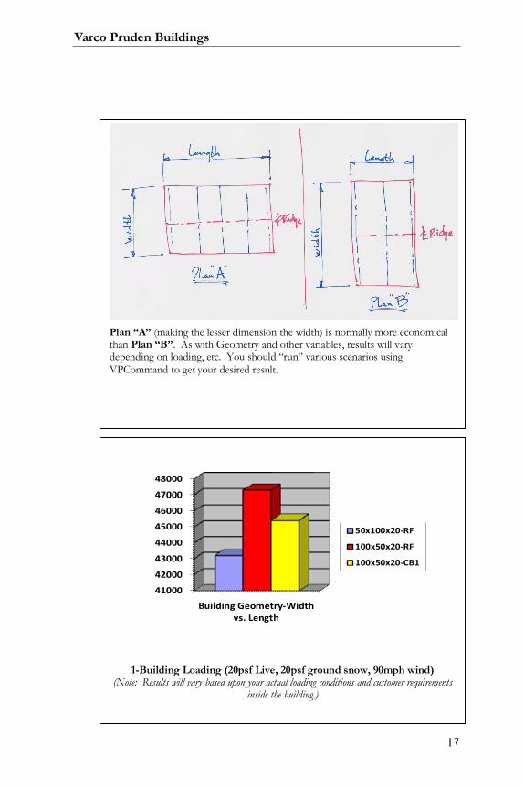
Plan “A” (making the lesser dimension the width) is normally more economicalthan Plan “B”. As with Geometry and other variables, results will varydepending on loading, etc. You should “run” various scenarios usingVPCommand to get your desired result.
41000
42000
43000
44000
45000
46000
47000
48000
Building Geometry-Widthvs. Length
50x100x20-RF
100x50x20-RF
100x50x20-CB1
1-Building Loading (20psf Live, 20psf ground snow, 90mph wind)(Note: Results will vary based upon your actual loading conditions and customer requirements
inside the building.)
Systems Guide
18
Inset girts could be used to obtain more horizontal clear dimension
between frames with the same outside dimensions. Be sure to compare the
increase in cost to the girts due to simple span condition. On larger buildings
with many girts it may make sense to increase the building’s overall width and
length and use continuous/outset secondary to meet your clearance needs.
Roof Pitch (Single Slope, Gabled, Unsymmetrical)
Appearance/ Flexibility: See Frame section for effect of
changing the roof pitch on each frame type.
o Generally, gable roof slopes are more cost effective
than single slopes. (See the chart on the following pages)
o Unsymmetrical roof pitches may be desired when one
area of the building requires greater clearance than other areas.
Site Drainage requirements: Verify with customer the
direction(s) for the roof water drainage. A restriction in direction could
dictate using a single slope roof vs. a gabled roof
Varco Pruden Buildings
19
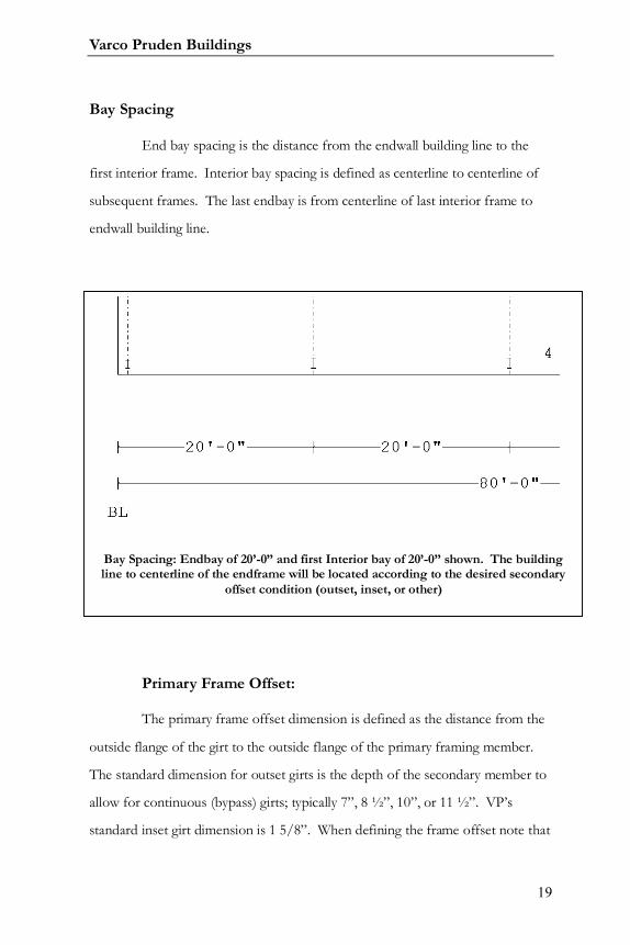
Bay Spacing
End bay spacing is the distance from the endwall building line to the
first interior frame. Interior bay spacing is defined as centerline to centerline of
subsequent frames. The last endbay is from centerline of last interior frame to
endwall building line.
Primary Frame Offset:
The primary frame offset dimension is defined as the distance from the
outside flange of the girt to the outside flange of the primary framing member.
The standard dimension for outset girts is the depth of the secondary member to
allow for continuous (bypass) girts; typically 7”, 8 ½”, 10”, or 11 ½”. VP’s
standard inset girt dimension is 1 5/8”. When defining the frame offset note that
Bay Spacing: Endbay of 20’-0” and first Interior bay of 20’-0” shown. The buildingline to centerline of the endframe will be located according to the desired secondary
offset condition (outset, inset, or other)

Systems Guide
20
the overall building line dimensions do not change (width and length), the
primary framing moves outward towards the building lines.
Frame Offset: Dimension from Building Line to outside flange of Primaryframing member. For outset girst the dimension is the girt depth (7”, 8 ½” 10”,
or 11 ½”); for VP standard inset girts the dimension is 1 5/8”. Other frameoffset dimensions may be used as desired.
Varco Pruden Buildings
21
Roof Height Change or Floor Elevation Change
For sites that are not level, it may be more economical to
consider floor elevation changes or roof height changes to minimize column
lengths.
Note that roof elevation changes may create snow drift
concerns in some climates.
Single Slope vs. Gable Slope
Gable slope buildings are less expensive than single slope
buildings in many cases.
Gables are more economical when the building loads are
heavier.
Gables typically offer larger savings in wider buildings than
narrow buildings.
As always, building codes have some impact on this
comparison.
Systems Guide
22
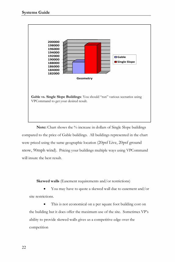
Note: Chart shows the % increase in dollars of Single Slope buildings
compared to the price of Gable buildings. All buildings represented in the chart
were priced using the same geographic location (20psf Live, 20psf ground
snow, 90mph wind). Pricing your buildings multiple ways using VPCommand
will insure the best result.
Skewed walls (Easement requirements and/or restrictions)
You may have to quote a skewed wall due to easement and/or
site restrictions.
This is not economical on a per square foot building cost on
the building but it does offer the maximum use of the site. Sometimes VP’s
ability to provide skewed walls gives us a competitive edge over the
competition
182000184000186000188000190000192000194000196000198000200000
Geometry
Gable
Single Slope
Gable vs. Single Slope Buildings: You should “run” various scenarios usingVPCommand to get your desired result.
Varco Pruden Buildings
23
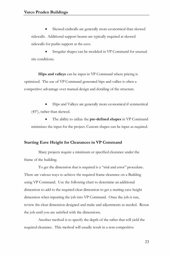
Skewed endwalls are generally more economical than skewed
sidewalls. Additional support beams are typically required at skewed
sidewalls for purlin support at the eave.
Irregular shapes can be modeled in VP Command for unusual
site conditions.
Hips and valleys can be input in VP Command where pricing is
optimized. The use of VP Command generated hips and vallies is often a
competitive advantage over manual design and detailing of the structure.
Hips and Valleys are generally more economical if symmetrical
(45º), rather than skewed.
The ability to utilize the pre-defined shapes in VP Command
minimizes the input for the project. Custom shapes can be input as required.
Starting Eave Height for Clearances in VP Command
Many projects require a minimum or specified clearance under the
frame of the building.
To get the dimension that is required is a “trial and error” procedure.
There are various ways to achieve the required frame clearance on a Building
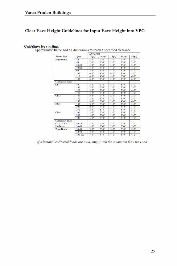
using VP Command. Use the following chart to determine an additional
dimension to add to the required clear dimension to get a starting eave height
dimension when inputting the job into VP Command. Once the job is run,
review the clear dimension designed and make and adjustments as needed. Rerun
the job until you are satisfied with the dimensions.
Another method is to specify the depth of the rafter that will yield the
required clearance. This method will usually result in a non-competitive

Systems Guide
24
(pricewise) design if you restrict the depth less than the program chooses. Input
the job and transfer the project for Interactive Frame Design (IA) assistance with
a note in the “frames note” section describing what you want. The designer will
attempt to design the frame for what is required and return the frame to you
based on the starting eave height you have input.
Request assistance from your VP Service Team to help determine the
correct eave height to satisfy the requirements.
Varco Pruden Buildings
25
Clear Eave Height Guidelines for Input Eave Height into VPC:

Systems Guide
26
Notes:

Varco Pruden Buildings
27
Notes:
Systems Guide
28
Attachments
What appearance options will be required for the building?
Questions for the Customer
Appearance considerations for attachments
Piggyback canopy?
Built-up canopy?
Façade?
Parapet?
Soffit?
Rake extension?
Optimization Concepts - Appearance considerations
Piggyback canopy
o Piggyback canopies can be more economical than
built-up canopies for canopies up to 6 ft. maximum projection.
o Piggyback canopies with a soffit make a nice clean
canopy by hiding all beams and secondary.
Built-up Canopy
o A built-up canopy requires a canopy beam and
additional flashing under the canopy.
o Not quite as clean as the Piggyback
o A built-up canopy can span up to 20 ft. or greater.
However, on the larger spans, a lean-to is more cost efficient.
o A soffit can be installed under the built-up canopy
but is not required.
Piggyback canopies are appropriate for cantilevers up to 6’ maximum
projection while built-up beam canopies can extend to larger lengths. Both have
Varco Pruden Buildings
29
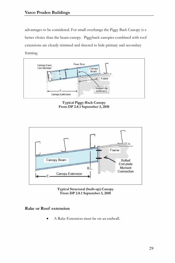
advantages to be considered. For small overhangs the Piggy Back Canopy is a
better choice than the beam canopy. Piggyback canopies combined with roof
extensions are cleanly trimmed and sheeted to hide primary and secondary
framing.
Rake or Roof extension
A Rake Extension must be on an endwall.
Typical Piggy-Back CanopyFrom DP 2.8.1 September 3, 2010
Typical Structural (built-up) CanopyFrom DP 2.8.1 September 3, 2010
Systems Guide
30
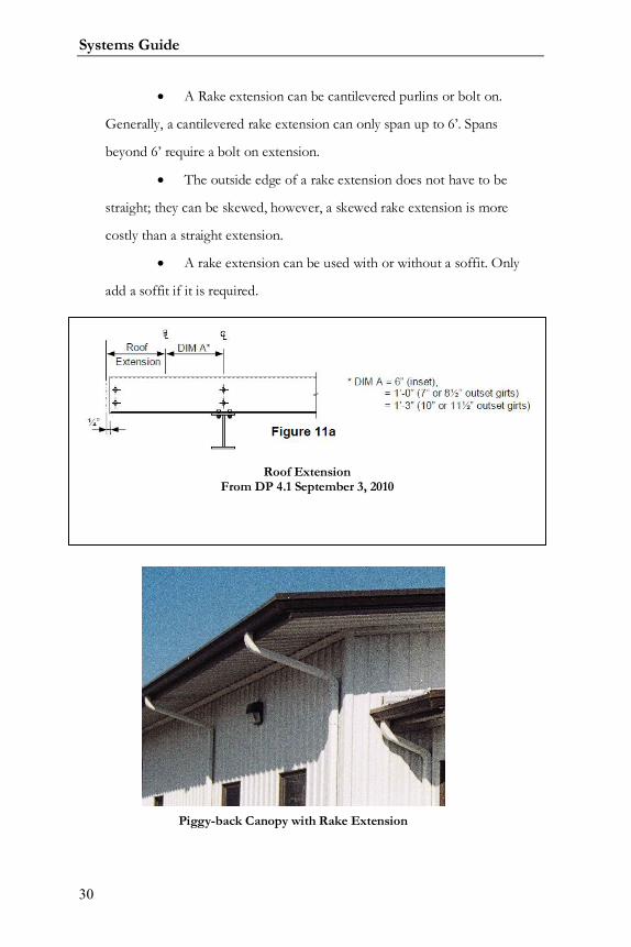
A Rake extension can be cantilevered purlins or bolt on.
Generally, a cantilevered rake extension can only span up to 6’. Spans
beyond 6’ require a bolt on extension.
The outside edge of a rake extension does not have to be
straight; they can be skewed, however, a skewed rake extension is more
costly than a straight extension.
A rake extension can be used with or without a soffit. Only
add a soffit if it is required.
Roof ExtensionFrom DP 4.1 September 3, 2010
Piggy-back Canopy with Rake Extension
Varco Pruden Buildings
31
Façade
The open façade, if allowed, is more economical than the
closed façade. The open façade is held outside of the building line and
standard gutters can be used. A closed facade requires multi-gutter and is
considerably more expensive.
Endwall facades are normally closed facades, but can be open
if required.
The sloped-mansard façade is generally the most expensive
façade system and should be avoided when possible. It is more difficult and
costly to erect.
Many times extending the sidewall above the roofline will serve
the same function as a façade at a reduced cost. (See parapets)
When using the FSX façade a minimum projection of 2’-0” is
required to keep the multi-gutter outside of the building line.
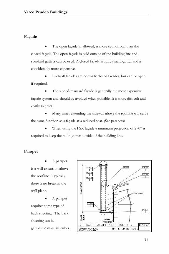
Parapet
A parapet
is a wall extension above
the roofline. Typically
there is no break in the
wall plane.
A parapet
requires some type of
back sheeting. The back
sheeting can be
galvalume material rather
Systems Guide
32
than the painted wall material.
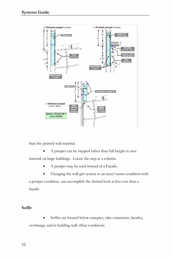
A parapet can be stepped rather than full height to save
material on large buildings. Locate the step at a column.
A parapet may be used instead of a Façade.
Changing the wall girt system to an inset/outset condition with
a parapet condition, can accomplish the desired look at less cost than a
façade.
Soffit
Soffits are located below canopies, rake extensions, facades,
overhangs, and in building wall offset conditions.
Varco Pruden Buildings
33
Additional framing is required for the support of the soffit
panels unless the soffit can be attached directly to the bottom of the purlins.
Many panels are available for use as soffits.
o Panel Rib and Vee Rib are the most economical
panels.
Soffit in VPCommand is input within the Liner folder.
VPCommand considers the panel on the back side of the main wall or roof
as Liner.
If the majority of your canopies / rake extensions require soffit
panel you should add these items to your VP Command “Default” files so
that soffit will automatically be provided.

Systems Guide
34
Notes:
Varco Pruden Buildings
35
Loading
The building will have to be designed to meet local codes and
requirements, but are there any special requirements the customer will require?
How does the loading impact the project?
Questions for the Customer
Site location and topography for the building (for code
information)
Wind exposure on the site?
Collateral loads (examples)?
Ceiling Types (Acoustical, Plaster, etc.)?
Sprinkler Lines?
Lighting?
HVAC Ducts?
Will special deflection requirements need to be considered?
Optimization Concepts
The answer to the questions allows the opportunity to consider the
various aspects that pertain to loading.
Codes
Governing Building Code: It is important to be
knowledgeable about the governing code that applies to the project location.
Systems Guide
36
Building Use / Importance Category
The building use can impact the loading factors for the project
Essential facilities, hazardous material storage or buildings
intended for high occupancy etc., will require higher load factors.
Building End Use (IBC, IBC based State Codes, ASCE7-02, ASCE7-05):
(From VPCommand Help Screen as of December 8, 2010: Revised: 04/01/08)
Low Hazard- Agricultural [I]: Building that represent a low hazard tohuman life in the event of a failure, such as:
o Agricultural facilities, certain temporary facilities, and Minorstorage facilities.
Standard Occupancy Structures [II]: Building and other structuresexcept those listed in Categories I, III and IV.
Special Occupancy Structures [III]: Building and other structuresthat represent a substantial hazard to human life in the event of a failure,such as:
o Buildings where more than 300 people congregate in one areao Buildings with elementary school, secondary school or day-
care facilitieso with a capacity greater than 250.Buildings with a capacity
greater than 500 people for colleges or adult education. Healthcare facilities with a capacity of 50 or more resident patientsbut not having surgery or emergency treatment facilities. Jailsand detention facilities
o Any occupancy with an occupant load greater than 5000.Power-generating stations, water treatment for potable water,wastewater treatment facilities and other public utilitiesfacilities not listed in Category III. Building not listed inCategory III containing sufficient quantities of toxic orexplosive substances to be dangerous to public if released
Essential Facilities (Hospitals, Fire, Police…) [IV]: Buildingdesignated as essential facilities, such as:
o Hospitals and other health facilities having surgery oremergency treatment facilities. Fire, rescue and police stationsand emergency vehicle garages. Designated earthquake,hurricane or other emergency shelters. Designated emergencypreparedness, communication, and operation centers. Powergenerating stations and other public utility facilities used forback-up facilities for Category III structures. Structures
Varco Pruden Buildings
37
containing high toxic materials. Aviation control towers, airtraffic control and emergency aircraft hangars. Buildingscritical to the national defense functions. Water treatmentfacilities required to maintain water pressure for firesuppression.
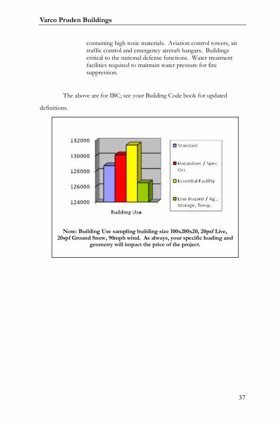
The above are for IBC; see your Building Code book for updated
definitions.
Note: Building Use sampling building size 100x200x20, 20psf Live,20spf Ground Snow, 90mph wind. As always, your specific loading and
geometry will impact the price of the project.
Systems Guide
38
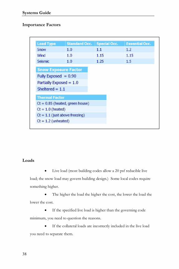
Importance Factors
Loads
Live load (most building codes allow a 20 psf reducible live
load; the snow load may govern building design.) Some local codes require
something higher.
The higher the load the higher the cost, the lower the load the
lower the cost.
If the specified live load is higher than the governing code
minimum, you need to question the reasons.
If the collateral loads are incorrectly included in the live load
you need to separate them.
Varco Pruden Buildings
39
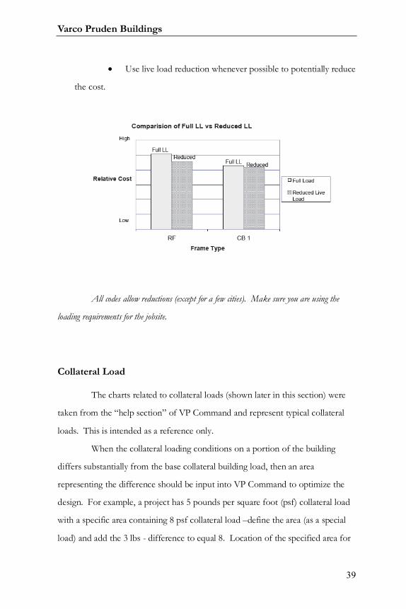
Use live load reduction whenever possible to potentially reduce
the cost.
All codes allow reductions (except for a few cities). Make sure you are using the
loading requirements for the jobsite.
Collateral Load
The charts related to collateral loads (shown later in this section) were
taken from the “help section” of VP Command and represent typical collateral
loads. This is intended as a reference only.
When the collateral loading conditions on a portion of the building
differs substantially from the base collateral building load, then an area
representing the difference should be input into VP Command to optimize the
design. For example, a project has 5 pounds per square foot (psf) collateral load
with a specific area containing 8 psf collateral load –define the area (as a special
load) and add the 3 lbs - difference to equal 8. Location of the specified area for
Systems Guide
40
the collateral load near a frame line or interior column lowers the impact over
loads placed in the center of the bay.
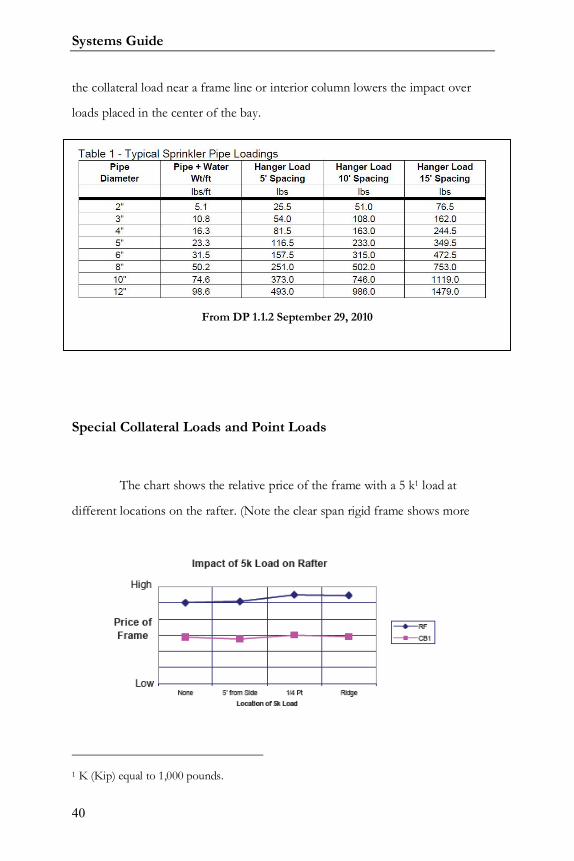
Special Collateral Loads and Point Loads
The chart shows the relative price of the frame with a 5 k1 load at
different locations on the rafter. (Note the clear span rigid frame shows more
1 K (Kip) equal to 1,000 pounds.
From DP 1.1.2 September 29, 2010
Varco Pruden Buildings
41
savings than the CB frame.) It is important to the economy of the building to
locate concentrated loads near supports rather than at mid bay or span. Even
more savings is possible if the loads are located near frame lines or columns.
Note: Examples of special collateral loads include, sprinkler, line loads,
cable trays, and catwalks. Examples of Point Loads include mechanical units,
basketball goals, and scoreboards.
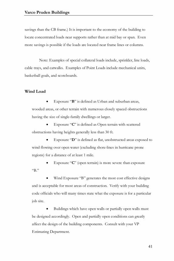
Wind Load
Exposure “B” is defined as Urban and suburban areas,
wooded areas, or other terrain with numerous closely spaced obstructions
having the size of single-family dwellings or larger.
Exposure “C” is defined as Open terrain with scattered
obstructions having heights generally less than 30 ft.
Exposure “D” is defined as flat, unobstructed areas exposed to
wind flowing over open water (excluding shore-lines in hurricane prone
regions) for a distance of at least 1 mile.
Exposure “C” (open terrain) is more severe than exposure
“B.”
Wind Exposure “B” generates the most cost effective designs
and is acceptable for most areas of construction. Verify with your building
code officials who will many times state what the exposure is for a particular
job site.
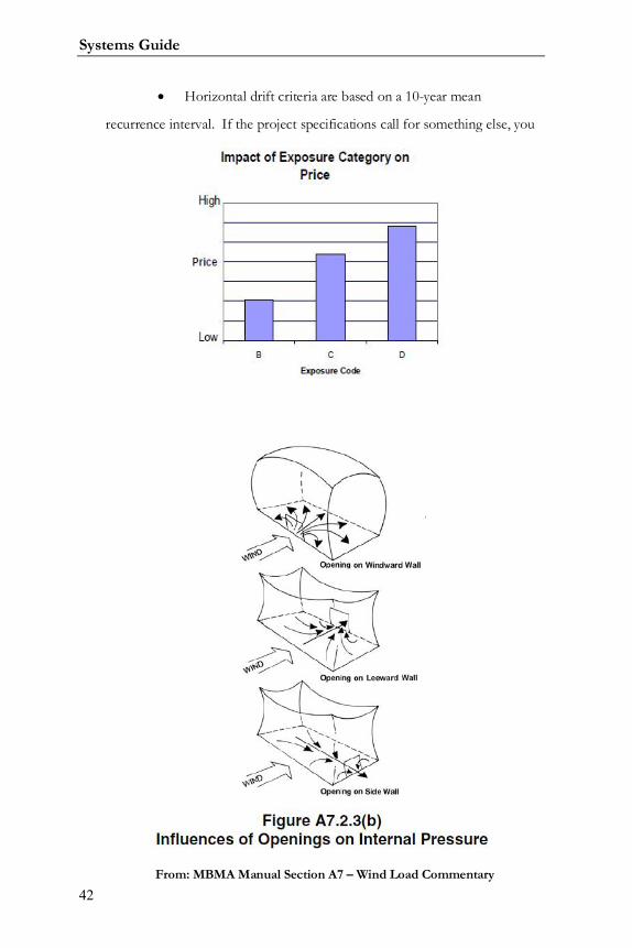
Buildings which have open walls or partially open walls must
be designed accordingly. Open and partially open conditions can greatly
affect the design of the building components. Consult with your VP
Estimating Department.
Systems Guide
42
Horizontal drift criteria are based on a 10-year mean
recurrence interval. If the project specifications call for something else, you
From: MBMA Manual Section A7 – Wind Load Commentary
Varco Pruden Buildings
43
need to contact your VP Service Center for assistance.
Always remember that defining horizontal drift requirements
can be very expensive.
Dead loads
Other roof construction impacts the dead load
Built up deck, roof by others, rubber roof, or specific dead
load included in the building specs.
The weight of the mezzanine structure and floor system is
considered dead loads.
Snow loads
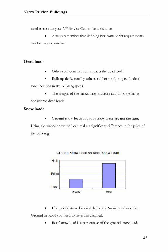
Ground snow loads and roof snow loads are not the same.
Using the wrong snow load can make a significant difference in the price of
the building.
If a specification does not define the Snow Load as either
Ground or Roof you need to have this clarified.
Roof snow load is a percentage of the ground snow load.
Systems Guide
44
Specify the proper snow exposure factor (fully exposed;
partially exposed; or sheltered)
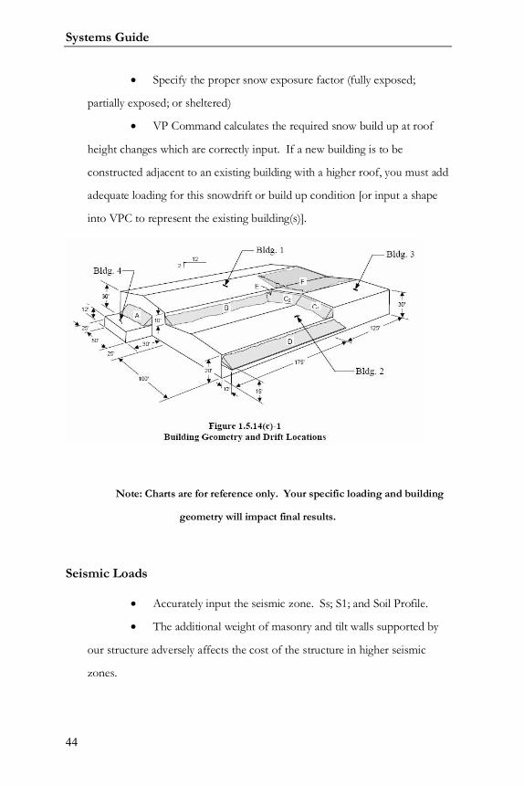
VP Command calculates the required snow build up at roof
height changes which are correctly input. If a new building is to be
constructed adjacent to an existing building with a higher roof, you must add
adequate loading for this snowdrift or build up condition [or input a shape
into VPC to represent the existing building(s)].
Note: Charts are for reference only. Your specific loading and building
geometry will impact final results.
Seismic Loads
Accurately input the seismic zone. Ss; S1; and Soil Profile.
The additional weight of masonry and tilt walls supported by
our structure adversely affects the cost of the structure in higher seismic
zones.
Varco Pruden Buildings
45
For larger projects with high seismic loads contact your VP
Service center for additional bracing options.
If the project has concrete or masonry walls contact your VP
service center to discuss the possibility of using those walls as shear walls to
reduce bracing cost.
Deflection Criteria
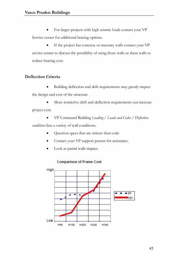
Building deflection and drift requirements may greatly impact
the design and cost of the structure.
More restrictive drift and deflection requirements can increase
project cost.
VP Command Building Loading / Loads and Codes / Deflection
conditions lists a variety of wall conditions.
Question specs that are stricter than code
Contact your VP support person for assistance.
Look at partial walls impact.
Systems Guide
46
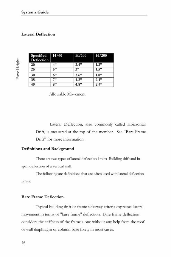
Lateral Deflection
Lateral Deflection, also commonly called Horizontal
Drift, is measured at the top of the member. See “Bare Frame
Drift” for more information.
Definitions and Background
There are two types of lateral deflection limits: Building drift and in-
span deflection of a vertical wall.
The following are definitions that are often used with lateral deflection
limits:
Bare Frame Deflection.
Typical building drift or frame sidesway criteria expresses lateral
movement in terms of "bare frame" deflection. Bare frame deflection
considers the stiffness of the frame alone without any help from the roof
or wall diaphragm or column base fixety in most cases.
Eav
e H
eight
Allowable Movement
SpecifiedDeflection
H/60 H/100 H/200
20 4” 2.4” 1.2”25 5” 3” 1.5”30 6” 3.6” 1.8”35 7” 4.2” 2.1”40 8” 4.8” 2.4”
Varco Pruden Buildings
47
Actual lateral deflections of completed buildings are less than theoretical
calculations for "bare frames". The MBMA Building Systems Manual goes into
great detail on this subject in Section C5.6 and Appendix A6. The MBMA
Manual and the AISC's Design Guide #3 "Serviceability Design Considerations
for Low Rise Buildings" both recommend using a 10-year mean recurrence wind
pressure instead of 50-year when calculating lateral deflections.
Ten-Year Wind:
A 10-year wind pressure can be approximated by 75% of the 50-
year wind pressure. AISC's Serviceability paper explains the philosophy
behind the 10-year wind: "Ten year recurrence interval winds are
recommended due to the non-catastrophic nature of serviceability issues
and the need to provide a standard consistent with day-to-day behavior
and average perceptions. Fifty-year winds are special events."
Frame Load Sharing:
Frame load sharing is an economical design method to reduce the
effects of concentrated lateral loads (lateral crane loads) applied on one
frame. A lateral force applied to one frame may be distributed to the
frames on either side by roof rod bracing or some other physical means.
Frame load sharing does not apply to lateral wind or seismic loads.
Further discussion of frame load sharing will be addressed in the later
section on Crane Buildings.
Systems Guide
48
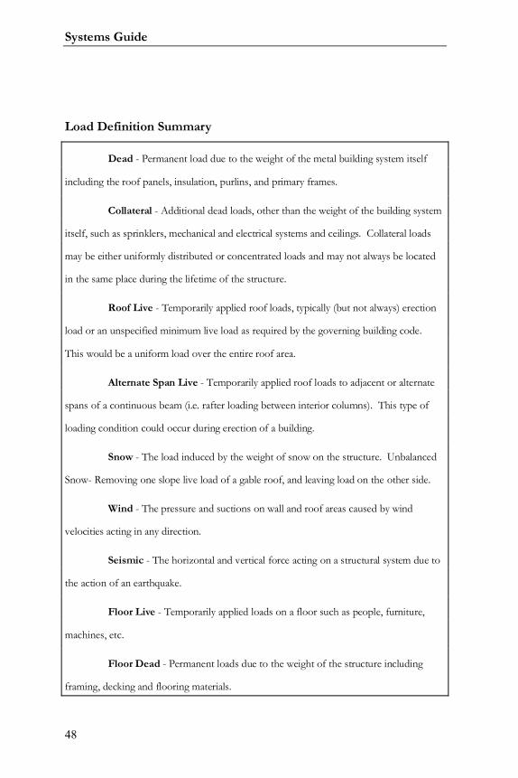
Load Definition Summary
Dead - Permanent load due to the weight of the metal building system itself
including the roof panels, insulation, purlins, and primary frames.
Collateral - Additional dead loads, other than the weight of the building system
itself, such as sprinklers, mechanical and electrical systems and ceilings. Collateral loads
may be either uniformly distributed or concentrated loads and may not always be located
in the same place during the lifetime of the structure.
Roof Live - Temporarily applied roof loads, typically (but not always) erection
load or an unspecified minimum live load as required by the governing building code.
This would be a uniform load over the entire roof area.
Alternate Span Live - Temporarily applied roof loads to adjacent or alternate
spans of a continuous beam (i.e. rafter loading between interior columns). This type of
loading condition could occur during erection of a building.
Snow - The load induced by the weight of snow on the structure. Unbalanced
Snow- Removing one slope live load of a gable roof, and leaving load on the other side.
Wind - The pressure and suctions on wall and roof areas caused by wind
velocities acting in any direction.
Seismic - The horizontal and vertical force acting on a structural system due to
the action of an earthquake.
Floor Live - Temporarily applied loads on a floor such as people, furniture,
machines, etc.
Floor Dead - Permanent loads due to the weight of the structure including
framing, decking and flooring materials.
Varco Pruden Buildings
49
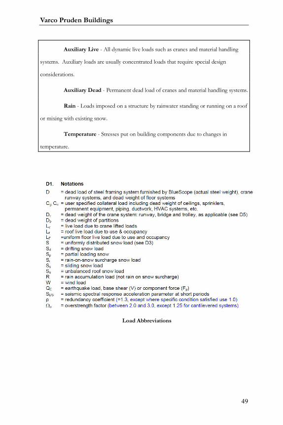
Auxiliary Live - All dynamic live loads such as cranes and material handling
systems. Auxiliary loads are usually concentrated loads that require special design
considerations.
Auxiliary Dead - Permanent dead load of cranes and material handling systems.
Rain - Loads imposed on a structure by rainwater standing or running on a roof
or mixing with existing snow.
Temperature - Stresses put on building components due to changes in
temperature.
Load Abbreviations
Systems Guide
50
Special Loads (examples)
Basketball Goals
Fall Protection
HVAC Equipment Location
Cranes / Monorails
Cable Trays
Future use for the building structure
Future Additions (Lean-to’s, additional bays, etc.)
Future Loading Changes
Site location for the building (for code information)
Exposure on the site (see Wind and Snow sections)
Possible impact from snow drift load from adjacent structures
Collateral loads (examples)
Ceiling Types (Acoustical, Plaster, etc.)
Sprinklers Lines
Lighting
HVAC Duct
Special deflection requirements need to be considered
Horizontal and vertical deflection criteria greatly impact the
building cost.
See serviceability chart for recommendations

Varco Pruden Buildings
51
Future use for the building structure
Future Additions (Lean-to’s, add bays, etc.)
Future Loading Changes
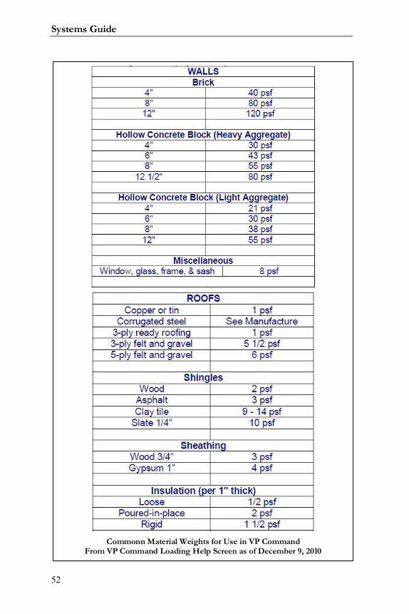
The approximate weights listed are commonly used for calculating the
weight of non-steel materials, per the latest AISC manual. Weights are
measured in pounds per square foot. The above weights are average weights
based on typical building materials obtained from standards accepted by the
construction industry. The weights of specific materials to be used on any
specific project should be verified. Weights of raw materials and material make-
up vary from region to region and manufacturer to manufacturer.
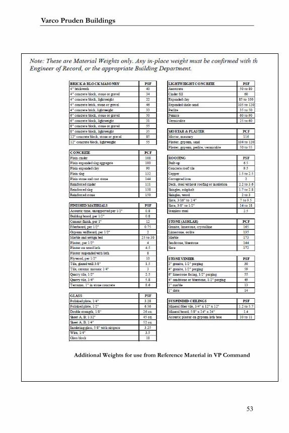
The following weights are average material weights only based on typical
building materials obtained from standards accepted by the construction industry.
The weights of specific materials to be used on any specific project should be
verified based on the actual materials to be used.
Actual “in-place weights” must be confirmed with the Engineer of
Record, or the appropriate building code official.
Systems Guide
52
Commonn Material Weights for Use in VP CommandFrom VP Command Loading Help Screen as of December 9, 2010
Varco Pruden Buildings
53
Additional Weights for use from Reference Material in VP Command

Systems Guide
54
Strength and Serviceability
Building codes and specifications require that every building be designed
to satisfy two fundamental criteria – strength and serviceability.
Strength
The building must be designed with adequate strength to resist all
environmental and user-imposed loads without structural failure. Structural
failure is generally defined as a condition in which one or more of the structural
elements of the building lose their ability to resist the forces that they are required
to carry in order to maintain the integrity of the building. Structural failures often
result in significant problems ranging from roof leaks to total collapse and can
pose a threat to property and life.
Serviceability
Each structural system within the building must be designed to provide
appropriate serviceability. This means that the structural systems must be able to
perform their intended functions without interfering with the buildings
operations. For example, a floor system must be designed with the appropriate
amount of stiffness. In some cases, when the designer has failed to adequately
consider this issue, floor vibrations have been so perceptible that building
occupants have refused to work in the building.
In most cases serviceability problems don’t represent any immediate
danger of structural failure. However, serviceability problems have the potential
to significantly reduce a building’s usefulness. Therefore, serviceability
Varco Pruden Buildings
55
considerations are often equally as important in the design of a building as its
strength.
The AISC's Design Guide #3 "Serviceability Design Considerations for
Low Rise Buildings" describes the difference between the two limit states and
gives some guidelines.
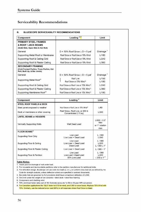
The serviceability limits on the following pages are recommended
guidelines for the design of building components and are based on the AISC's
Design Guide #3 "Serviceability Design Considerations for Low Rise Buildings."
These values may be overridden by any specifications, applicable local building
code criteria, or owner's choice. The criteria set in this document provide
recommendations for customer consideration.
Most buildings are required to have an “Engineer of Record” who
assumes the responsibility for the building. She is registered to practice
engineering in the building location and is responsible for sealing the building
documents for the governing municipality. Normally she will specify with the
owner’s consent the serviceability requirements for the building. When she does
not, the only governing measure for design is the governing codes and good
engineering practice.
Systems Guide
56
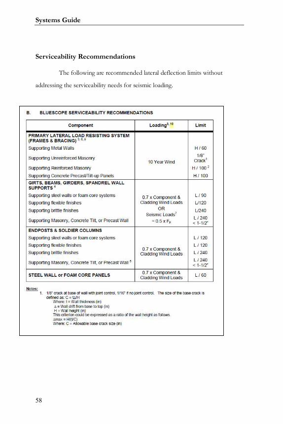
Serviceability Recommendations
from: DP 06-02 February 2, 2010
Varco Pruden Buildings
57
Component Loading Limit 1,3
Notes:
Deflection limits are based on information obtained from
AISC's Design Guide #3 "Serviceability Design Considerations For Low
Rise Buildings,"1990.
Insure positive drainage of roof under load.
Refer to applicable Building Code for other deflection limits.
For moveable and de-mountable partitions refer to
manufacturer for additional limits.
Recommended minimum roof slope of ¼: 12 for Standing
Seam roofs and ½: 12 for exposed fastener roofs.
Systems Guide
58
Serviceability Recommendations
The following are recommended lateral deflection limits without
addressing the serviceability needs for seismic loading.
Varco Pruden Buildings
59
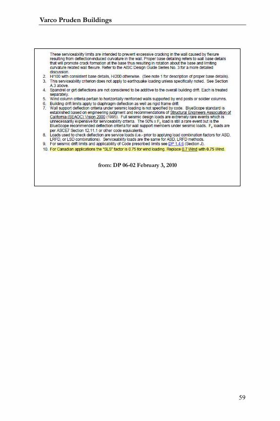
from: DP 06-02 February 3, 2010

Systems Guide
60
Notes:

Varco Pruden Buildings
61
Notes:

Systems Guide
62
Notes:

Varco Pruden Buildings
63
Notes:

Systems Guide
64
Varco Pruden Buildings
65
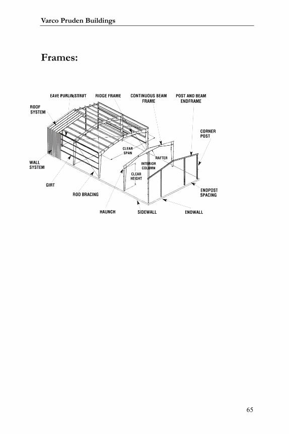
Frames:
Systems Guide
66
Frames
The answers to the questions in this section are vital to the economy of
the building. The decisions on framing will greatly affect the project price.
Questions for the Customer
Can we use the most economical framing system and bay spacing?
Are there any clearance requirements (horizontal and vertical)?
Can we use the most economical interior column spacing and configuration
(pipe, tube, three-plate)?
Are there any restrictions or preferences that would control the selection of
Solid Web over Open Web framing? (lighting, mechanical equipment distribution, inside
clearances.)
Are there special access requirements for the building (entry, loading dock ,
specialty doors)?
Can we use the most economical frame design for the roof pitch?
Do you have any limitations/restrictions for the exterior columns
(configuration, depth, tapered, straight, supermarket, etc.)?
Can columns be flange braced to walls not by VP?
Are the wall systems load-bearing?
Identify column base conditions and elevations?
Do you expect future expansions to affect the endwall and sidewall design?
Frame Optimization Concepts
General
Bay Spacing: Optimize the bay spacing for the length of the building.
Bay space economy is clearly defined by the best overall building price. In some
cases, the bay spacing may favor one parameter for the frame spacing and
Varco Pruden Buildings
67
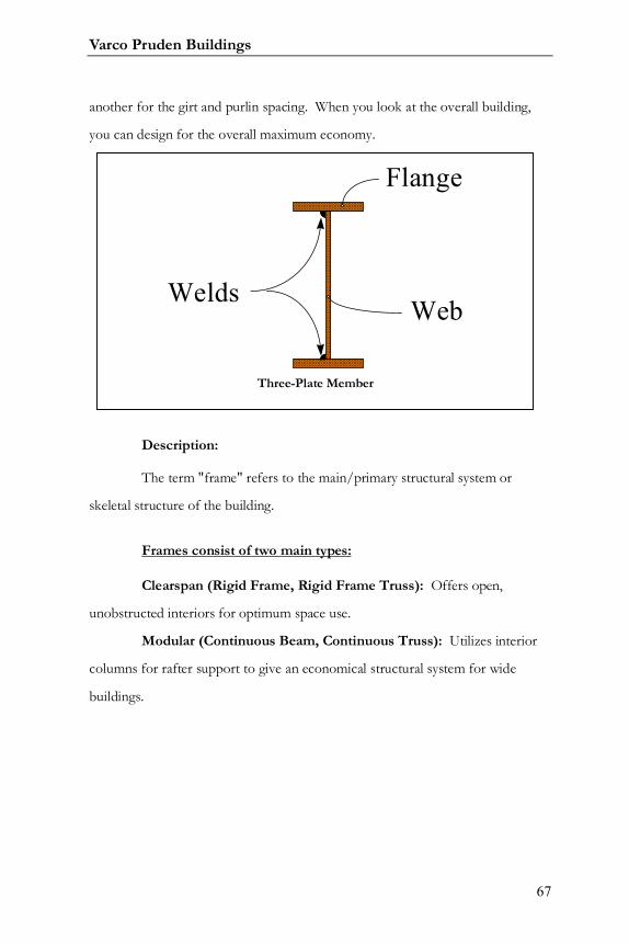
another for the girt and purlin spacing. When you look at the overall building,
you can design for the overall maximum economy.
Description:
The term "frame" refers to the main/primary structural system or
skeletal structure of the building.
Frames consist of two main types:
Clearspan (Rigid Frame, Rigid Frame Truss): Offers open,
unobstructed interiors for optimum space use.
Modular (Continuous Beam, Continuous Truss): Utilizes interior
columns for rafter support to give an economical structural system for wide
buildings.
Flange
WebWelds
Three-Plate Member
Systems Guide
68
Frames contain two main parts:
Column: A fabricated solid web member used in a vertical position to
transfer loads from the rafters to the foundation. This member also supports the
wall system (secondary and covering).
Rafter: A fabricated member that is the main beam supporting the roof
system (secondary and covering).
Buildings contain end frames and interior frames:
End Frames: These are located at each end of the building. Available
end frame types include: post & beam, half-load and full-load. Only a full-load
frame is designed for future expansion. Both the half load and full load end
frames may or may not have end posts. End frames are discussed in more detail
in the section called Endwall Framing.
Interior Frames: Located at interior bays of the building, interior
frames are full load frames.
Frames General Information:
VP Buildings’ frames normally consist of tapered (angled, non-parallel
flanges) or straight rafters connected to tapered or straight vertical solid web
columns. The frames may be designed with a centered ridge, off-center ridge, or
as a single slope. Eave heights and spans are dimensioned in increments of 1/16"
- within manufacturing limitations. Frames are built with variable roof pitches, as
determined by Roof Covering types.
Varco Pruden Buildings
69
Any sidewall girt placement can be utilized, including outset, inset, or
flush mounted. This topic will be covered in greater detail in the “Secondary
Framing” section.
Systems Guide
70
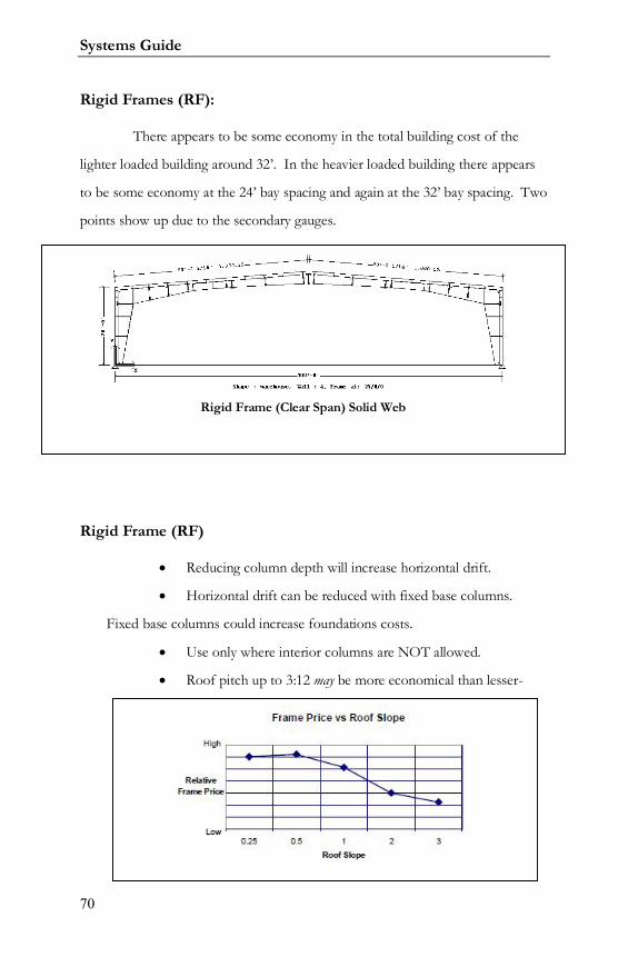
Rigid Frames (RF):
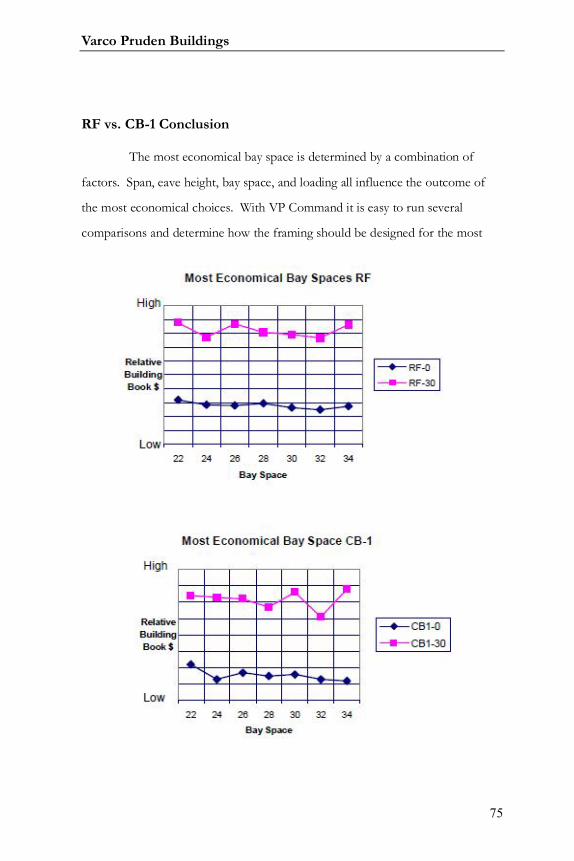
There appears to be some economy in the total building cost of the
lighter loaded building around 32’. In the heavier loaded building there appears
to be some economy at the 24’ bay spacing and again at the 32’ bay spacing. Two
points show up due to the secondary gauges.
Rigid Frame (RF)
Reducing column depth will increase horizontal drift.
Horizontal drift can be reduced with fixed base columns.
Fixed base columns could increase foundations costs.
Use only where interior columns are NOT allowed.
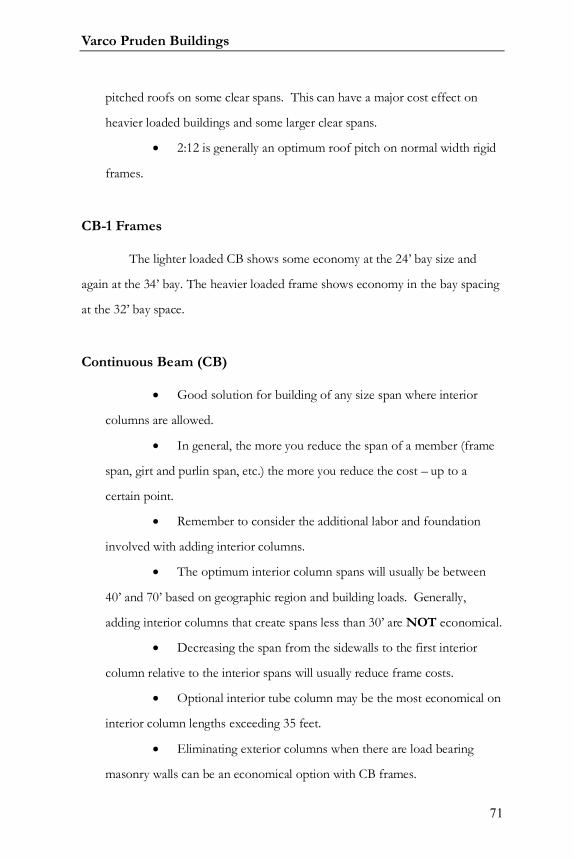
Roof pitch up to 3:12 may be more economical than lesser-
Rigid Frame (Clear Span) Solid Web
Varco Pruden Buildings
71
pitched roofs on some clear spans. This can have a major cost effect on
heavier loaded buildings and some larger clear spans.
2:12 is generally an optimum roof pitch on normal width rigid
frames.
CB-1 Frames
The lighter loaded CB shows some economy at the 24’ bay size and
again at the 34’ bay. The heavier loaded frame shows economy in the bay spacing
at the 32’ bay space.
Continuous Beam (CB)
Good solution for building of any size span where interior
columns are allowed.
In general, the more you reduce the span of a member (frame
span, girt and purlin span, etc.) the more you reduce the cost – up to a
certain point.
Remember to consider the additional labor and foundation
involved with adding interior columns.
The optimum interior column spans will usually be between
40’ and 70’ based on geographic region and building loads. Generally,
adding interior columns that create spans less than 30’ are NOT economical.
Decreasing the span from the sidewalls to the first interior
column relative to the interior spans will usually reduce frame costs.
Optional interior tube column may be the most economical on
interior column lengths exceeding 35 feet.
Eliminating exterior columns when there are load bearing
masonry walls can be an economical option with CB frames.
Systems Guide
72
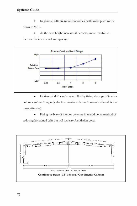
In general, CBs are more economical with lower pitch roofs
down to ¼:12.
As the eave height increases it becomes more feasible to
increase the interior column spacing.
Horizontal drift can be controlled by fixing the tops of interior
columns (often fixing only the first interior column from each sidewall is the
most effective)
Fixing the base of interior columns is an additional method of
reducing horizontal drift but will increase foundation costs.
Continuous Beam (CB-1 Shown) One Interior Column
Varco Pruden Buildings
73
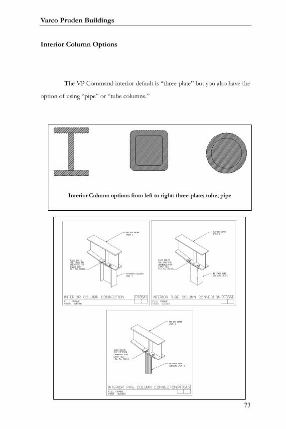
Interior Column Options
The VP Command interior default is “three-plate” but you also have the
option of using “pipe” or “tube columns.”
Interior Column options from left to right: three-plate; tube; pipe
Systems Guide
74
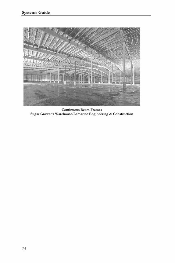
Continuous Beam FramesSugar Grower’s Warehouse-Lemartec Engineering & Construction
Varco Pruden Buildings
75
RF vs. CB-1 Conclusion
The most economical bay space is determined by a combination of
factors. Span, eave height, bay space, and loading all influence the outcome of
the most economical choices. With VP Command it is easy to run several
comparisons and determine how the framing should be designed for the most
Systems Guide
76
economy.
If possible make the end bays smaller than the interior bays to decrease
the loading on the members and thus lowering the cost of the secondary and the
frames.
Interior Columns used with Interior Frames
Interior columns (at Continuous Beam [CB] or Continuous Truss [CT]
frames) exist solely to support something – a rafter, or a crane, or simply a girt –
but their proper application is critical. As taught in our Product Seminar, the
more you reduce the span of a member, the more you reduce the cost – up to a
certain point. For example, placing an interior column in the middle of a 200’-0”
spanning frame will significantly decrease the cost of that frame under nearly any
loading condition. Adding a second interior column can reduce the cost further.
Your loading (Live, snow, etc.) will dictate what interior column spacing makes
sense for your specific project. A project in Georgia (with less snow) can have
greater interior column spacing than one in Maine – if cost is the driving factor.
It is important to remember that while you may be reducing the cost of
your frame, you must consider the additional material and labor cost involved in
the foundation and erection of the additional columns. Thus, saving a few
hundred dollars on a frame may not justify what you will ultimately spend for
total in-place cost and may even lose in flexibility in having the additional interior
columns.
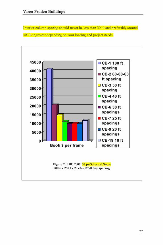
Figures 1 and 2 below show the pricing results for Continuous Beam
frames containing interior columns at varying spacing under 70 psf and 10 psf
Ground Snow respectively. Note that these are for interior frames. Generally,
Varco Pruden Buildings
77
Interior column spacing should never be less than 30’-0 and preferably around
40’-0 or greater depending on your loading and project needs.
0
5000
10000
15000
20000
25000
30000
35000
40000
45000
Book $ per frame
CB-1 100 ftspacingCB-2 60-80-60ft spacingCB-3 50 ftspacingCB-4 40 ftspacingCB-6 30 ftspacingsCB-7 25 ftspacingsCB-9 20 ftspacingsCB-19 10 ftspacings
Figure 2: IBC 2006, 10 psf Ground Snow200w x 250 l x 20 eh – 25’-0 bay spacing

Systems Guide
78
In both examples shown in Figs. 1 and 2 notice that the CB-19 is more
costly than the CB-9, plus you have much more foundation and labor costs to
consider!
Interior Columns used with End Frames
There are times when you need to use Continuous Beam (or
Continuous Truss) frames at an endwall, such as when too much sheeting and
girt material must be removed for brick, glass, large framed openings, or other
and a Post and Beam is no longer stable, thus a half-load frame must be used.
CB or CT frames with Interior columns at an economical (and logical)
spacing combined with “endposts” is a much better option than using a CB
0
2000
4000
6000
8000
10000
12000
14000
Book $ per frame
CB-1 100 ftspacingCB-2 60-80-60ft spacingCB-3 50 ftspacingCB-4 40 ftspacingCB-6 30 ftspacingsCB-7 25 ftspacingsCB-9 20 ftspacingsCB-19 10 ftspacings
Figure 2: IBC 2000, 10 psf Ground Snow200w x 250 l x 20 eh – 25’-0 bay spacing
Varco Pruden Buildings
79
frame with Interior Columns spaced as you would for a typical endframe: for
example, 24’-0 center span with 25’-0 spans approaching the sidewalls.
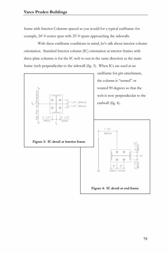
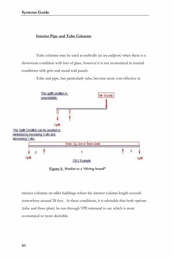
With these endframe conditions in mind, let’s talk about interior column
orientation. Standard Interior column (IC) orientation at interior frames with
three-plate columns is for the IC web to run in the same direction as the main
frame (web perpendicular to the sidewall (fig. 3). When ICs are used at an
endframe for girt attachment,
the column is “turned” or
rotated 90 degrees so that the
web is now perpendicular to the
endwall (fig. 4).
Figure 4: IC detail at end frame
Figure 3: IC detail at interior frame
Systems Guide
80
Interior Pipe and Tube Columns
Tube columns may be used at endwalls (as an endpost) when there is a
showroom condition with lots of glass, however it is not economical in normal
conditions with girts and metal wall panels.
Tube and pipe, but particularly tube, become more cost effective at
interior columns on taller buildings where the interior column length exceeds
somewhere around 28 feet. At these conditions, it is advisable that both options
(tube and three-plate) be run through VPCommand to see which is most
economical or more desirable.
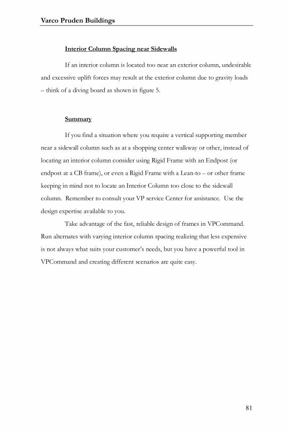
Figure 5: Similar to a “diving board”
Varco Pruden Buildings
81
Interior Column Spacing near Sidewalls
If an interior column is located too near an exterior column, undesirable
and excessive uplift forces may result at the exterior column due to gravity loads
– think of a diving board as shown in figure 5.
Summary
If you find a situation where you require a vertical supporting member
near a sidewall column such as at a shopping center walkway or other, instead of
locating an interior column consider using Rigid Frame with an Endpost (or
endpost at a CB frame), or even a Rigid Frame with a Lean-to – or other frame
keeping in mind not to locate an Interior Column too close to the sidewall
column. Remember to consult your VP service Center for assistance. Use the
design expertise available to you.
Take advantage of the fast, reliable design of frames in VPCommand.
Run alternates with varying interior column spacing realizing that less expensive
is not always what suits your customer’s needs, but you have a powerful tool in
VPCommand and creating different scenarios are quite easy.
Systems Guide
82
Frame Span
Try to span the frames the shortest dimension of the building to reduce
cost. See Basic Geometry section.
Frames and Roof Slope
Generally buildings with symmetrical gabled roofs are less expensive
than those using single slope.
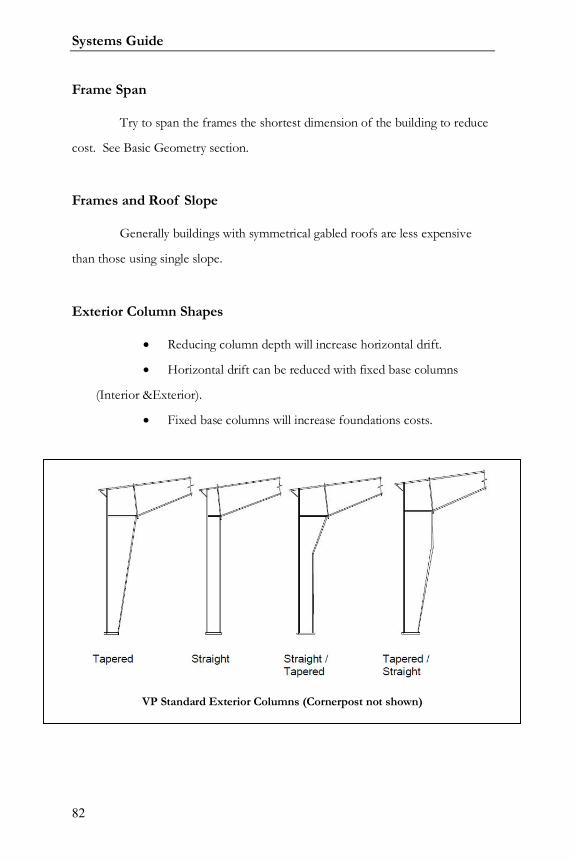
Exterior Column Shapes
Reducing column depth will increase horizontal drift.
Horizontal drift can be reduced with fixed base columns
(Interior &Exterior).
Fixed base columns will increase foundations costs.
VP Standard Exterior Columns (Cornerpost not shown)
Varco Pruden Buildings
83
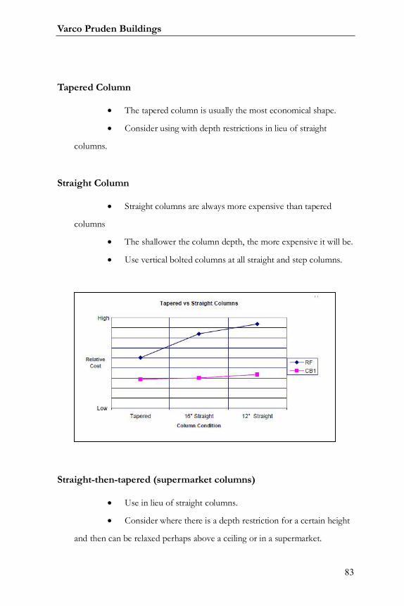
Tapered Column
The tapered column is usually the most economical shape.
Consider using with depth restrictions in lieu of straight
columns.
Straight Column
Straight columns are always more expensive than tapered
columns
The shallower the column depth, the more expensive it will be.
Use vertical bolted columns at all straight and step columns.
Straight-then-tapered (supermarket columns)
Use in lieu of straight columns.
Consider where there is a depth restriction for a certain height
and then can be relaxed perhaps above a ceiling or in a supermarket.
Systems Guide
84
The column type is most economical when the tapered portion
is at least 4’ long.
Tapered then Straight Column
Use when horizontal clearances are dictated in the upper
portion of the building such as buildings with cranes.
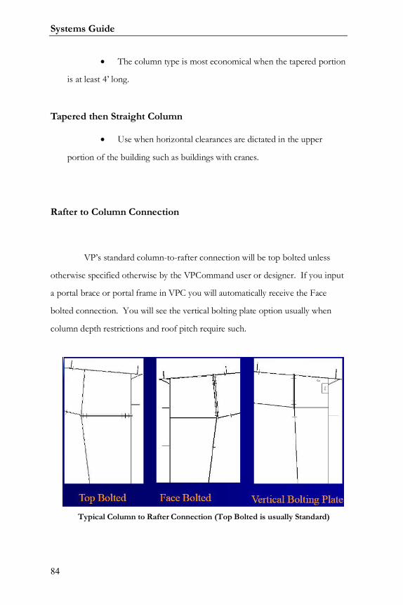
Rafter to Column Connection
VP’s standard column-to-rafter connection will be top bolted unless
otherwise specified otherwise by the VPCommand user or designer. If you input
a portal brace or portal frame in VPC you will automatically receive the Face
bolted connection. You will see the vertical bolting plate option usually when
column depth restrictions and roof pitch require such.
Typical Column to Rafter Connection (Top Bolted is usually Standard)
Varco Pruden Buildings
85
Other Frame Types
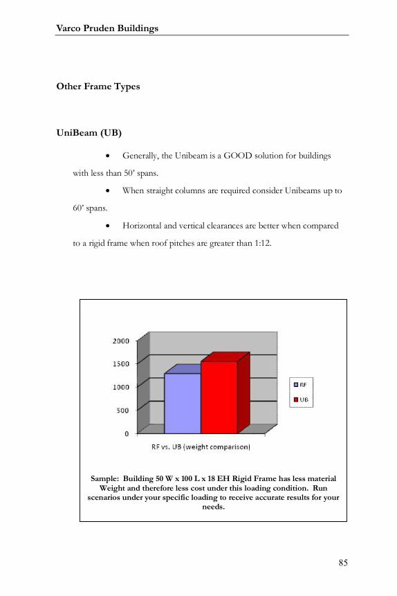
UniBeam (UB)
Generally, the Unibeam is a GOOD solution for buildings
with less than 50’ spans.
When straight columns are required consider Unibeams up to
60’ spans.
Horizontal and vertical clearances are better when compared
to a rigid frame when roof pitches are greater than 1:12.
Sample: Building 50 W x 100 L x 18 EH Rigid Frame has less materialWeight and therefore less cost under this loading condition. Run
scenarios under your specific loading to receive accurate results for yourneeds.
Systems Guide
86
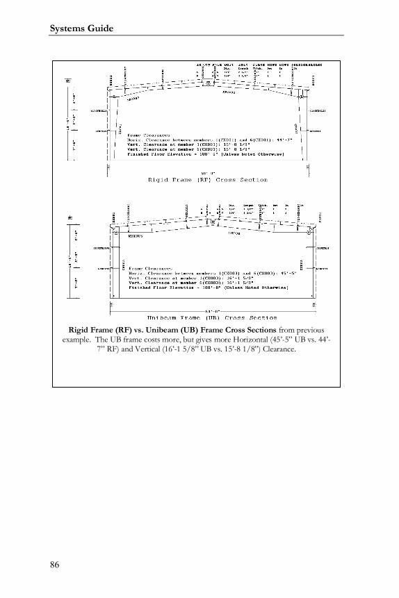
Rigid Frame (RF) vs. Unibeam (UB) Frame Cross Sections from previousexample. The UB frame costs more, but gives more Horizontal (45’-5” UB vs. 44’-
7” RF) and Vertical (16’-1 5/8” UB vs. 15’-8 1/8”) Clearance.
Varco Pruden Buildings
87
Post and Beam (PB)
PBs most economical when designed with gauge material.
Consider endpost spacing other than VP Standard spacing for
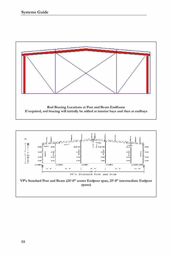
economy. VP’s standard endpost spacing is 12’-6” off the ridge (24’-0”
center span), 25’-0” intermediate spacing, and whatever is left over less than
25’-0”.
Consider reducing Endpost spacing to use 7” girts. Consider
as well the additional concrete for endposts.
If 8-1/2”, 10, or 11 ½” girts are required expand the spacing
to accommodate.
If possible, use the same end post spacing at each endwall for
most economical bracing design.
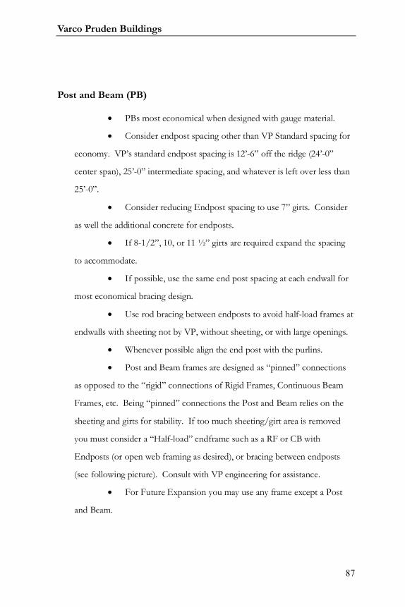
Use rod bracing between endposts to avoid half-load frames at
endwalls with sheeting not by VP, without sheeting, or with large openings.
Whenever possible align the end post with the purlins.
Post and Beam frames are designed as “pinned” connections
as opposed to the “rigid” connections of Rigid Frames, Continuous Beam
Frames, etc. Being “pinned” connections the Post and Beam relies on the
sheeting and girts for stability. If too much sheeting/girt area is removed
you must consider a “Half-load” endframe such as a RF or CB with
Endposts (or open web framing as desired), or bracing between endposts
(see following picture). Consult with VP engineering for assistance.
For Future Expansion you may use any frame except a Post
and Beam.
Systems Guide
88
VP’s Standard Post and Beam (24’-0” center Endpost span, 25’-0” intermediate Endpostspans)
Rod Bracing Locations at Post and Beam EndframeIf required, rod bracing will initially be added at interior bays and then at endbays
Varco Pruden Buildings
89
Lean –to (LT)
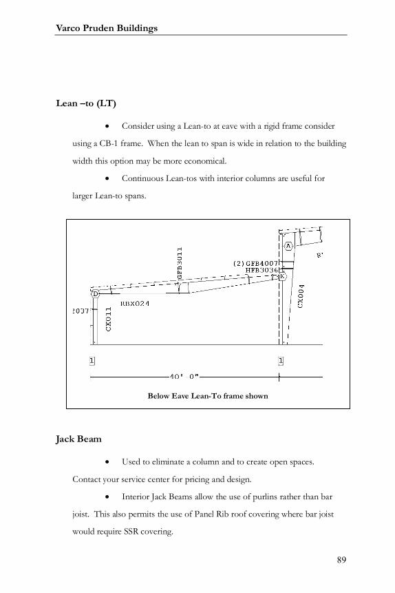
Consider using a Lean-to at eave with a rigid frame consider
using a CB-1 frame. When the lean to span is wide in relation to the building
width this option may be more economical.
Continuous Lean-tos with interior columns are useful for
larger Lean-to spans.
Jack Beam
Used to eliminate a column and to create open spaces.
Contact your service center for pricing and design.
Interior Jack Beams allow the use of purlins rather than bar
joist. This also permits the use of Panel Rib roof covering where bar joist
would require SSR covering.
Below Eave Lean-To frame shown
Systems Guide
90
Open Web Frames (Wind Bents and Truss Frames)
Excellent frame choice for large clear spans (such as arenas,
hangars, sporting complexes, etc.) and heavy loadings.
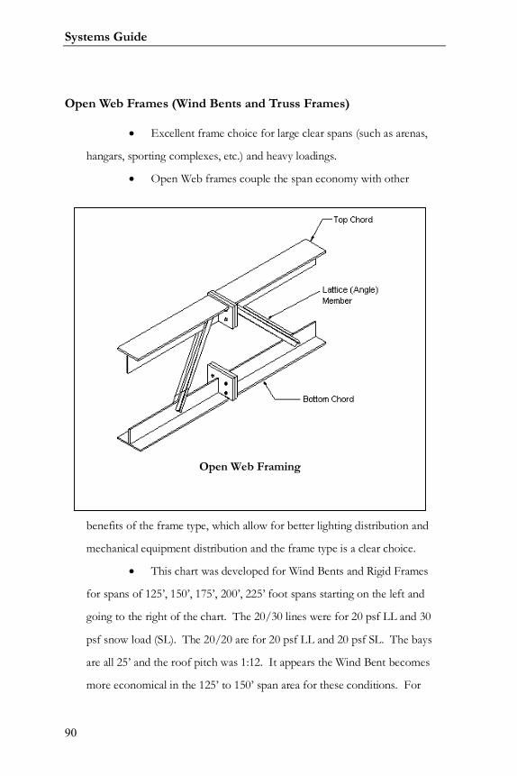
Open Web frames couple the span economy with other
benefits of the frame type, which allow for better lighting distribution and
mechanical equipment distribution and the frame type is a clear choice.
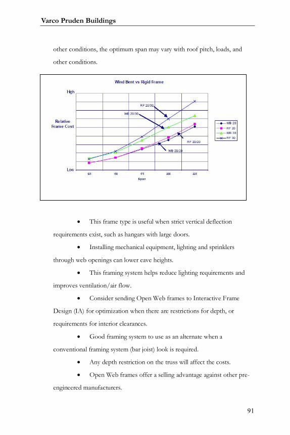
This chart was developed for Wind Bents and Rigid Frames
for spans of 125’, 150’, 175’, 200’, 225’ foot spans starting on the left and
going to the right of the chart. The 20/30 lines were for 20 psf LL and 30
psf snow load (SL). The 20/20 are for 20 psf LL and 20 psf SL. The bays
are all 25’ and the roof pitch was 1:12. It appears the Wind Bent becomes
more economical in the 125’ to 150’ span area for these conditions. For
Open Web Framing
Varco Pruden Buildings
91
other conditions, the optimum span may vary with roof pitch, loads, and
other conditions.
This frame type is useful when strict vertical deflection
requirements exist, such as hangars with large doors.
Installing mechanical equipment, lighting and sprinklers
through web openings can lower eave heights.
This framing system helps reduce lighting requirements and
improves ventilation/air flow.
Consider sending Open Web frames to Interactive Frame
Design (IA) for optimization when there are restrictions for depth, or
requirements for interior clearances.
Good framing system to use as an alternate when a
conventional framing system (bar joist) look is required.
Any depth restriction on the truss will affect the costs.
Open Web frames offer a selling advantage against other pre-
engineered manufacturers.
Systems Guide
92
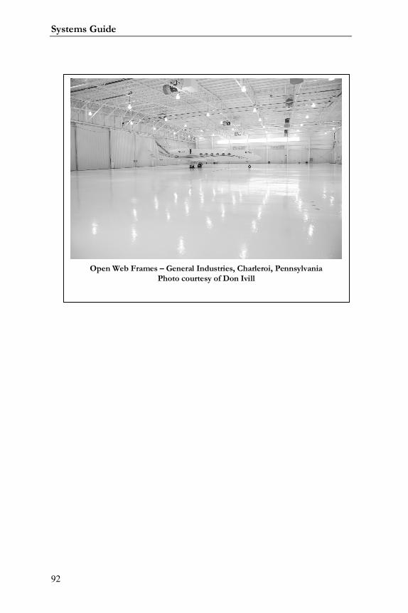
Open Web Frames – General Industries, Charleroi, PennsylvaniaPhoto courtesy of Don Ivill
Varco Pruden Buildings
93
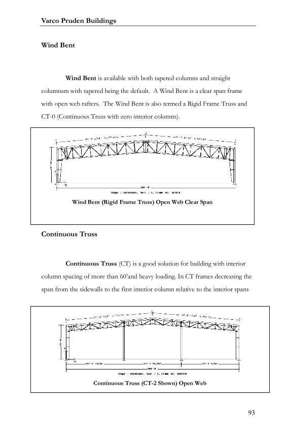
Wind Bent
Wind Bent is available with both tapered columns and straight
columnsm with tapered being the default. A Wind Bent is a clear span frame
with open web rafters. The Wind Bent is also termed a Rigid Frame Truss and
CT-0 (Continuous Truss with zero interior columns).
Continuous Truss
Continuous Truss (CT) is a good solution for building with interior
column spacing of more than 60’and heavy loading. In CT frames decreasing the
span from the sidewalls to the first interior column relative to the interior spans
Wind Bent (Rigid Frame Truss) Open Web Clear Span
Continuous Truss (CT-2 Shown) Open Web
Systems Guide
94
will usually reduce frame costs. CTs are available with both tapered columns and
straight columns with tapered being the default.
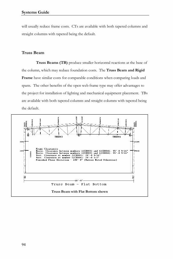
Truss Beam
Truss Beams (TB) produce smaller horizontal reactions at the base of
the column, which may reduce foundation costs. The Truss Beam and Rigid
Frame have similar costs for comparable conditions when comparing loads and
spans. The other benefits of the open web frame type may offer advantages to
the project for installation of lighting and mechanical equipment placement. TBs
are available with both tapered columns and straight columns with tapered being
the default.
Truss Beam with Flat Bottom shown
Varco Pruden Buildings
95
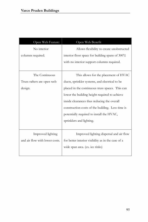
Open Web Feature: Open Web Benefit
No interior
columns required.
Allows flexibility to create unobstructed
interior floor space for building spans of 300'±
with no interior support columns required.
The Continuous
Truss rafters are open web
design.
This allows for the placement of HVAC
ducts, sprinkler systems, and electrical to be
placed in the continuous truss spaces. This can
lower the building height required to achieve
inside clearances thus reducing the overall
construction costs of the building. Less time is
potentially required to install the HVAC,
sprinklers and lighting.
Improved lighting
and air flow with lower costs.
Improved lighting dispersal and air flow
for better interior visibility as in the case of a
wide span area. (ex. ice rinks)
Systems Guide
96
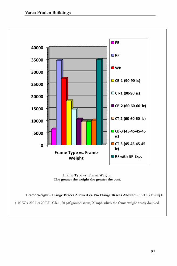
Frame Cost Comparisons:
The below frame comparisons are based on a building geometry of 180
W x 400 L x 20 EH; 30 psf GS, 90 mph Wind, 20 psf Live.
The more steel, the higher the cost - Open Web framing is more
economical than Solid Web the larger the tributary area and the heavier the loads.
As Interior Columns are added, the tributary is reduced, thus the difference in
price between open and solid lessens until the trend is reversed and Solid Web
becomes less expensive.
If you are uncertain what frame type to use or interior column is best
with continuous beam and continuous truss frames, you can input a building into
VP Command, locate various frame types throughout your shape (I used PB, RF,
WB, CB-1, CT-1, CB-2, CT-2, CB-3, CT-3, RF w/EP). In my example, the CT-2
with Interior Column spacing at 60-60-60 might be desired for its econimical
value, ease of erectibility, and open web benefits (placing ducts, wiring, etc. in
ewb area).
Remember that results vill vary depending upon your actual geometry
and loading conditions.
Varco Pruden Buildings
97
0
5000
10000
15000
20000
25000
30000
35000
40000
Frame Type vs. FrameWeight
PB
RF
WB
CB-1 (90-90 ic)
CT-1 (90-90 ic)
CB-2 (60-60-60 ic)
CT-2 (60-60-60 ic)
CB-3 (45-45-45-45ic)
CT-3 (45-45-45-45ic)
RF with EP Exp.
Frame Type vs. Frame Weight:The greater the weight the greater the cost.
Frame Weight – Flange Braces Allowed vs. No Flange Braces Allowed – In This Example
(100 W x 200 L x 20 EH, CB-1, 20 psf ground snow, 90 mph wind) the frame weight nearly doubled.
Systems Guide
98
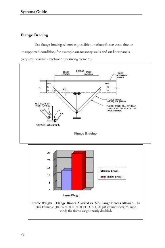
Flange Bracing
Use flange bracing wherever possible to reduce frame costs due to
unsupported condition; for example on masonry walls and on liner panels
(requires positive attachment to strong element).
Eliminating flange braces on rafter sections is very costly. For rafter
conditions that are boxed use flange braces on one side to reduce box width.
Flange Bracing
Frame Weight – Flange Braces Allowed vs. No Flange Braces Allowed – InThis Example (100 W x 200 L x 20 EH, CB-1, 20 psf ground snow, 90 mph
wind) the frame weight nearly doubled.
Varco Pruden Buildings
99
Notes:
Systems Guide
100
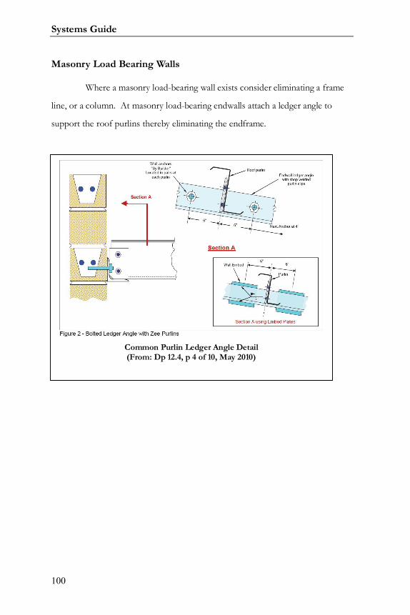
Masonry Load Bearing Walls
Where a masonry load-bearing wall exists consider eliminating a frame
line, or a column. At masonry load-bearing endwalls attach a ledger angle to
support the roof purlins thereby eliminating the endframe.
Common Purlin Ledger Angle Detail(From: Dp 12.4, p 4 of 10, May 2010)
Varco Pruden Buildings
101
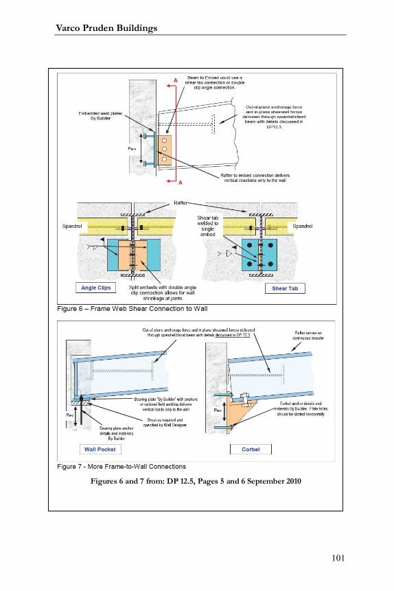
Figures 6 and 7 from: DP 12.5, Pages 5 and 6 September 2010
Systems Guide
102
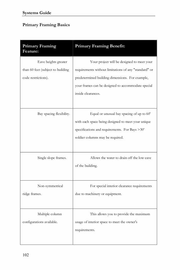
Primary Framing Basics
Primary FramingFeature:
Primary Framing Benefit:
Eave heights greater
than 60 feet (subject to building
code restrictions).
Your project will be designed to meet your
requirements without limitations of any "standard" or
predetermined building dimensions. For example,
your frames can be designed to accommodate special
inside clearances.
Bay spacing flexibility. Equal or unusual bay spacing of up to 60'
with each space being designed to meet your unique
specifications and requirements. For Bays >30’
soldier columns may be required.
Single slope frames. Allows the water to drain off the low eave
of the building.
Non-symmetrical
ridge frames.
For special interior clearance requirements
due to machinery or equipment.
Multiple column
configurations available.
This allows you to provide the maximum
usage of interior space to meet the owner's
requirements.
Varco Pruden Buildings
103
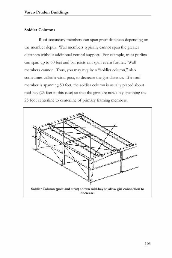
Soldier Columns
Roof secondary members can span great distances depending on
the member depth. Wall members typically cannot span the greater
distances without additional vertical support. For example, truss purlins
can span up to 60 feet and bar joists can span evern further. Wall
members cannot. Thus, you may require a “soldier column,” also
sometimes called a wind post, to decrease the girt distance. If a roof
member is spanning 50 feet, the soldier column is usually placed about
mid-bay (25 feet in this case) so that the girts are now only spanning the
25 foot centerline to centerline of primary framing members.
Soldier Column (post and strut) shown mid-bay to allow girt connection todecrease.

Systems Guide
104
Notes:

Varco Pruden Buildings
105
Notes:

Systems Guide
106
Varco Pruden Buildings
107
Cranes
When cranes are involved in the project, get as much information about
the equipment as possible, including the intended use of the cranes.
Questions for the Customer
Will this building have any crane(s) now or in the future?
If there are multiple cranes will they be operating in the same bay at the
same time?
Has the crane(s) manufacturer been determined? If so, is the crane data
information sheet available? If not, whom should I contact for detailed crane information?
Who supplies crane accessories & support members (beams, stops, rails
etc…)?
What is the crane layout and traveling direction?
Can we use bracing between the interior columns (are there any workflow
concerns that would prevent interior bracing)?
Crane Optimization Concepts
Make sure you know the classification of the crane
(A,B,C,D,E,F – See Crane Service Classifications at the end of this
section.)
Know as much as you can about wheel loadings, bridge
weight, trolley weight, crane operations, type, clearances, etc. in order to get
the best price on the buildings. (See order clarification form) or crane data
sheet from supplier.
Different classifications of cranes dictate the deflection and
drift on the building and crane girder system. If a higher classification is
used than is required, the price of the building will be impacted.
Systems Guide
108
Remote controls have the same impact on the building as cab
operated. Use pendant controls in lieu of remote controls if possible.
All buildings with class E or F should be priced by the VP
Buildings’ Estimating Group.
Position the crane with the bridge spanning the width of the
building rather than the length for best cost.
In most cases, smaller bay spacing will be more economical.
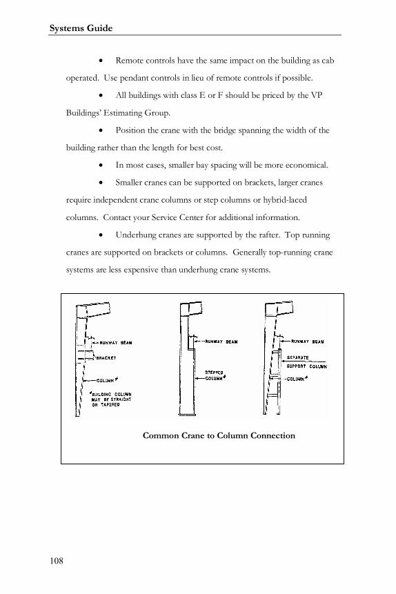
Smaller cranes can be supported on brackets, larger cranes
require independent crane columns or step columns or hybrid-laced
columns. Contact your Service Center for additional information.
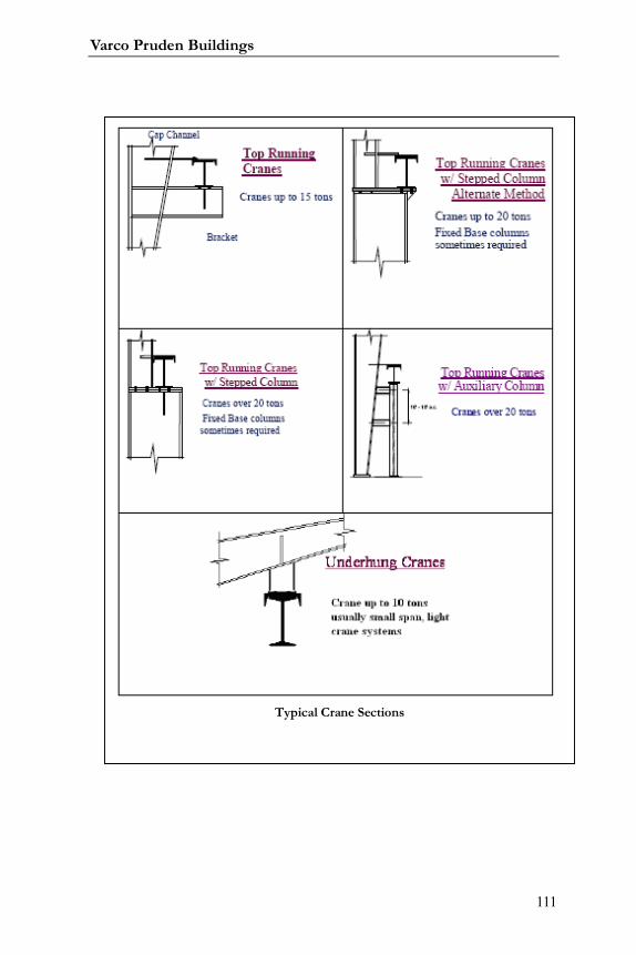
Underhung cranes are supported by the rafter. Top running
cranes are supported on brackets or columns. Generally top-running crane
systems are less expensive than underhung crane systems.
Common Crane to Column Connection
Varco Pruden Buildings
109
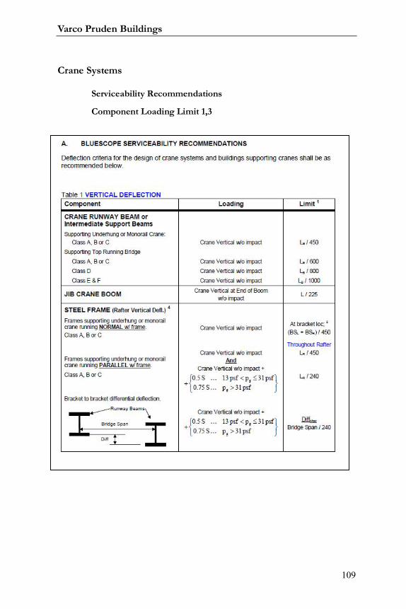
Crane Systems
Serviceability Recommendations
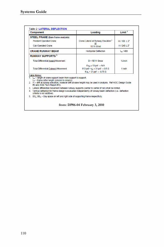
Component Loading Limit 1,3
Systems Guide
110
from: DP06-04 February 3, 2010
Varco Pruden Buildings
111
Typical Crane Sections

Systems Guide
112
Crane Service Classifications
From: MBMA Manual Section II - Cranes

Varco Pruden Buildings
113
Notes:

Systems Guide
114
Notes:

Varco Pruden Buildings
115
Systems Guide
116
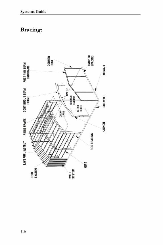
Bracing:
Varco Pruden Buildings
117
Systems Guide
118
Bracing
All buildings require bracing. In this section we want to determine the
most economical type and what flexibility is allowed in its location.
Questions for the Customer
Are the wall-opening locations defined?
Will the walls be available for rod bracing?
Are there any workflow requirements that would not allow rod bracing or
portal frames between interior columns (for wide buildings and mezzanines)?
Can we use bracing in the endwall?
Do you plan any future expansion to the building?
If the walls are masonry/tilt-up can we utilize them as Shear walls?

Varco Pruden Buildings
119
Systems Guide
120
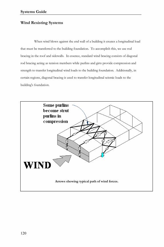
Wind Resisting Systems
When wind blows against the end wall of a building it creates a longitudinal load
that must be transferred to the building foundation. To accomplish this, we use rod
bracing in the roof and sidewalls. In essence, standard wind bracing consists of diagonal
rod bracing acting as tension members while purlins and girts provide compression and
strength to transfer longitudinal wind loads to the building foundation. Additionally, in
certain regions, diagonal bracing is used to transfer longitudinal seismic loads to the
building's foundation.
Arrows showing typical path of wind forces.
Varco Pruden Buildings
121
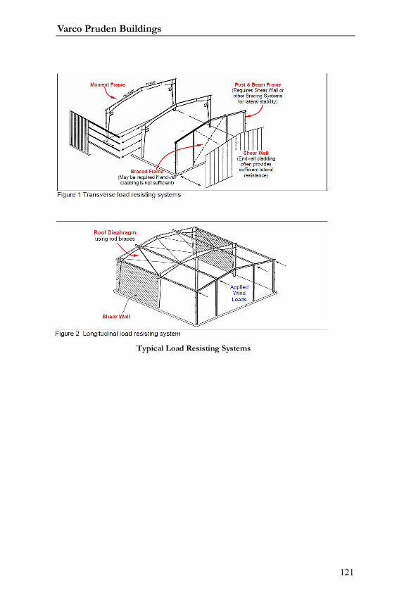
Typical Load Resisting Systems
Systems Guide
122
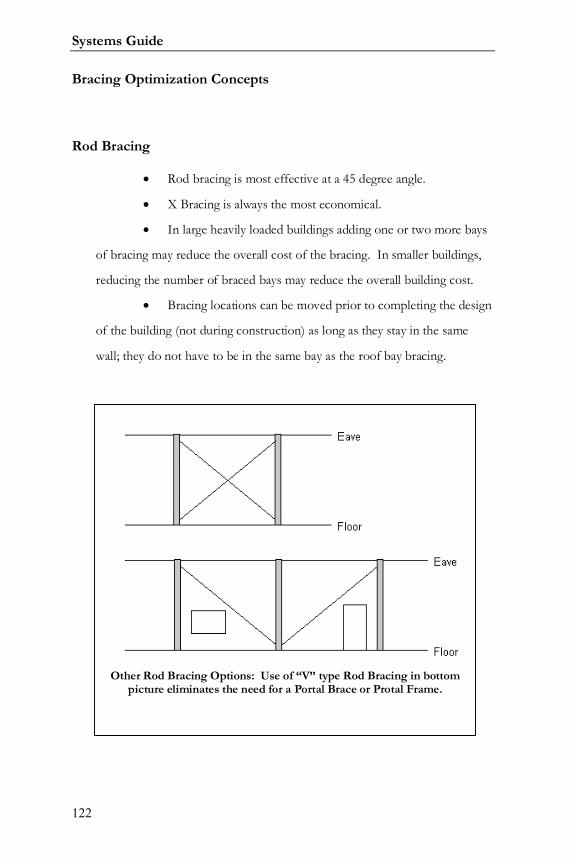
Bracing Optimization Concepts
Rod Bracing
Rod bracing is most effective at a 45 degree angle.
X Bracing is always the most economical.
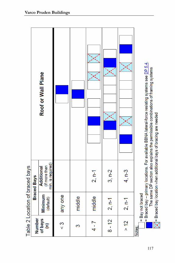
In large heavily loaded buildings adding one or two more bays
of bracing may reduce the overall cost of the bracing. In smaller buildings,
reducing the number of braced bays may reduce the overall building cost.
Bracing locations can be moved prior to completing the design
of the building (not during construction) as long as they stay in the same
wall; they do not have to be in the same bay as the roof bay bracing.
Other Rod Bracing Options: Use of “V” type Rod Bracing in bottompicture eliminates the need for a Portal Brace or Protal Frame.
Varco Pruden Buildings
123
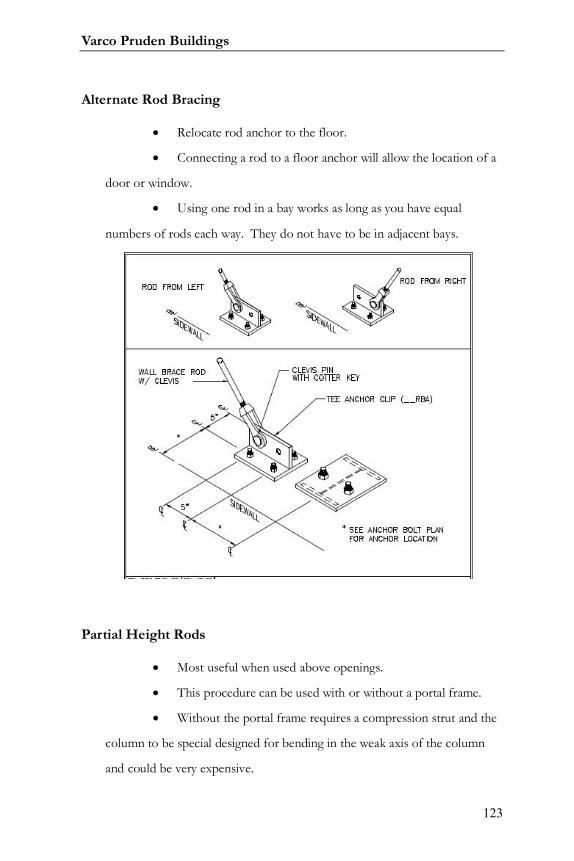
Alternate Rod Bracing
Relocate rod anchor to the floor.
Connecting a rod to a floor anchor will allow the location of a
door or window.
Using one rod in a bay works as long as you have equal
numbers of rods each way. They do not have to be in adjacent bays.
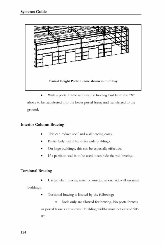
Partial Height Rods
Most useful when used above openings.
This procedure can be used with or without a portal frame.
Without the portal frame requires a compression strut and the
column to be special designed for bending in the weak axis of the column
and could be very expensive.
Systems Guide
124
With a portal frame requires the bracing load from the “X”
above to be transferred into the lower portal frame and transferred to the
ground.
Interior Column Bracing
This can reduce roof and wall bracing costs.
Particularly useful for extra wide buildings.
On large buildings, this can be especially effective.
If a partition wall is to be used it can hide the rod bracing.
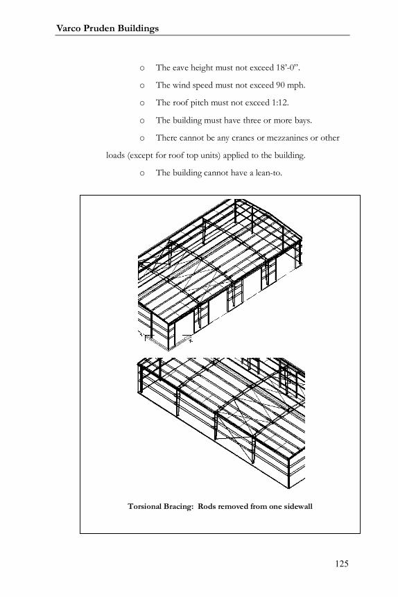
Torsional Bracing
Useful when bracing must be omitted in one sidewall on small
buildings.
Torsional bracing is limited by the following:
o Rods only are allowed for bracing. No portal braces
or portal frames are allowed. Building widths must not exceed 50’-
0”.
Partial Height Portal Frame shown in third bay
Varco Pruden Buildings
125
o The eave height must not exceed 18’-0”.
o The wind speed must not exceed 90 mph.
o The roof pitch must not exceed 1:12.
o The building must have three or more bays.
o There cannot be any cranes or mezzanines or other
loads (except for roof top units) applied to the building.
o The building cannot have a lean-to.
Torsional Bracing: Rods removed from one sidewall
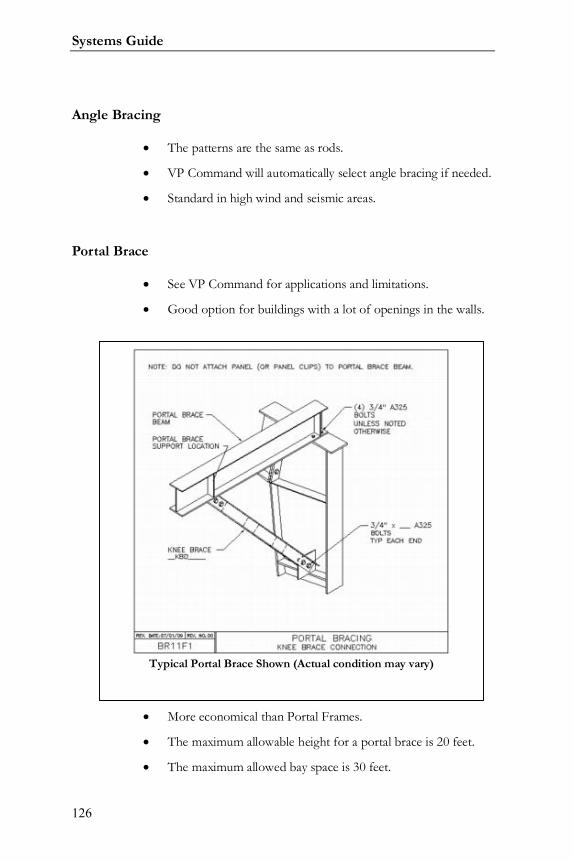
Systems Guide
126
Angle Bracing
The patterns are the same as rods.
VP Command will automatically select angle bracing if needed.
Standard in high wind and seismic areas.
Portal Brace
See VP Command for applications and limitations.
Good option for buildings with a lot of openings in the walls.
More economical than Portal Frames.
The maximum allowable height for a portal brace is 20 feet.
The maximum allowed bay space is 30 feet.
Typical Portal Brace Shown (Actual condition may vary)
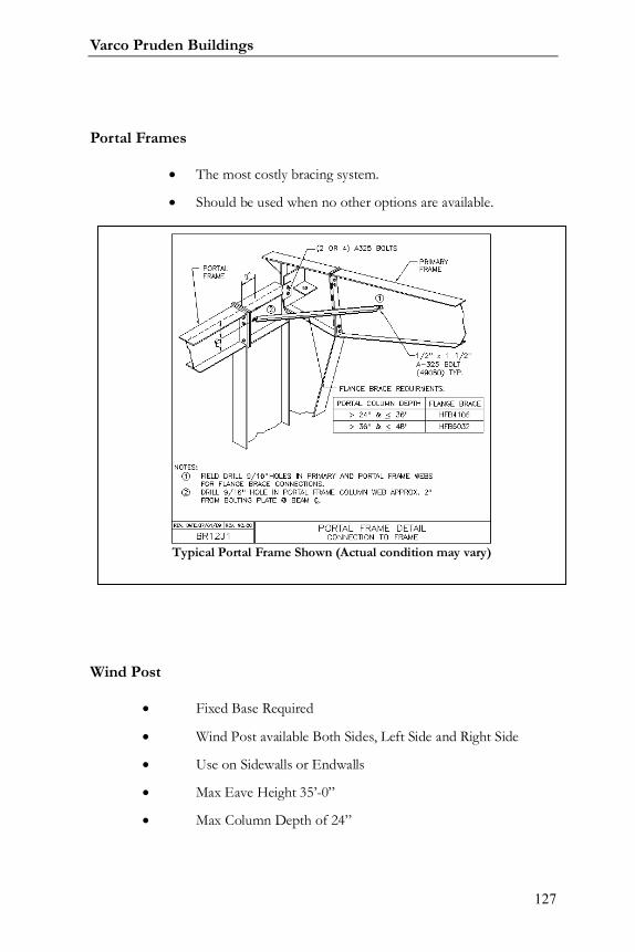
Varco Pruden Buildings
127
Portal Frames
The most costly bracing system.
Should be used when no other options are available.
Wind Post
Fixed Base Required
Wind Post available Both Sides, Left Side and Right Side
Use on Sidewalls or Endwalls
Max Eave Height 35’-0”
Max Column Depth of 24”
Typical Portal Frame Shown (Actual condition may vary)
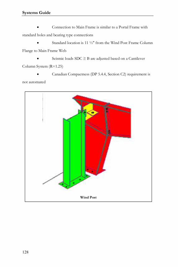
Systems Guide
128
Connection to Main Frame is similar to a Portal Frame with
standard holes and bearing type connections
Standard location is 11 ½" from the Wind Post Frame Column
Flange to Main Frame Web
Seismic loads SDC B are adjusted based on a Cantilever
Column System (R=1.25)
Canadian Compactness (DP 5.4.4, Section C2) requirement is
not automated
Wind Post
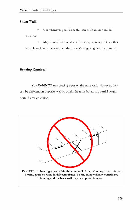
Varco Pruden Buildings
129
Shear Walls
Use whenever possible as this can offer an economical
solution.
May be used with reinforced masonry, concrete tilt or other
suitable wall construction when the owners’ design engineer is consulted.
Bracing Caution!
You CANNOT mix bracing types on the same wall. However, they
can be different on opposite wall or within the same bay as in a partial height
portal frame condition.
DO NOT mix bracing types within the same wall plane. You may have differentbracing types on walls in different planes, i.e. the front wall may contain rod
bracing and the back wall may have portal bracing.
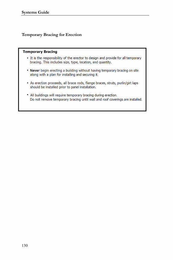
Systems Guide
130
Temporary Bracing for Erection
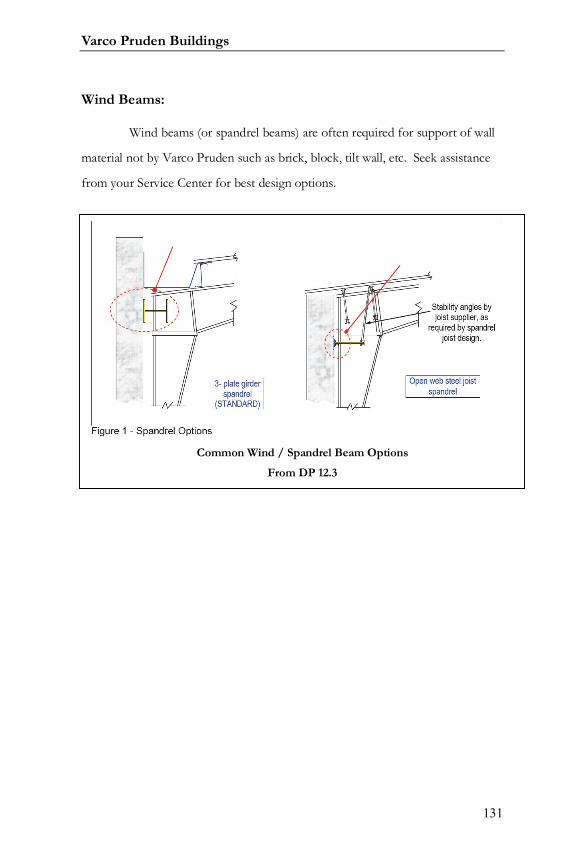
Varco Pruden Buildings
131
Wind Beams:
Wind beams (or spandrel beams) are often required for support of wall
material not by Varco Pruden such as brick, block, tilt wall, etc. Seek assistance
from your Service Center for best design options.
Common Wind / Spandrel Beam Options
From DP 12.3

Systems Guide
132
Notes:

Varco Pruden Buildings
133
Notes:
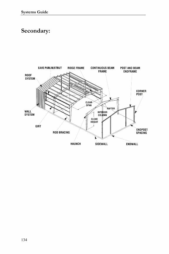
Systems Guide
134
Secondary:
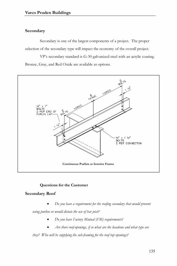
Varco Pruden Buildings
135
Secondary
Secondary is one of the largest components of a project. The proper
selection of the secondary type will impact the economy of the overall project.
VP’s secondary standard is G-30 galvanized steel with an acrylic coating.
Bronze, Gray, and Red Oxide are available as options.
Questions for the Customer
Secondary Roof
Do you have a requirement for the roofing secondary that would prevent
using purlins or would dictate the use of bar joist?
Do you have Factory Mutual (FM) requirements?
Are there roof-openings, if so what are the locations and what type are
they? Who will be supplying the sub-framing for the roof top openings?
Continuous Purlins at Interior Frame
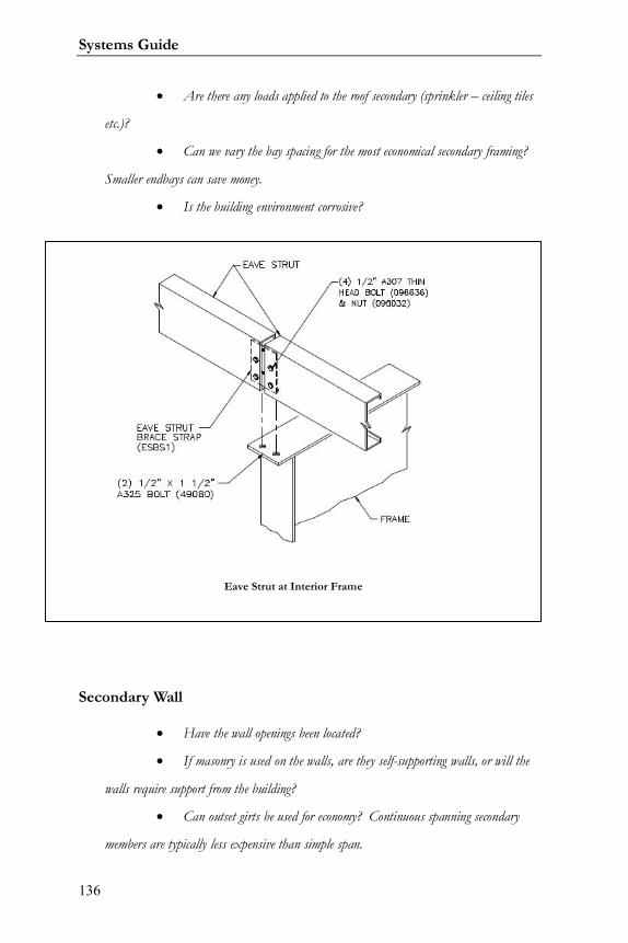
Systems Guide
136
Are there any loads applied to the roof secondary (sprinkler – ceiling tiles
etc.)?
Can we vary the bay spacing for the most economical secondary framing?
Smaller endbays can save money.
Is the building environment corrosive?
Secondary Wall
Have the wall openings been located?
If masonry is used on the walls, are they self-supporting walls, or will the
walls require support from the building?
Can outset girts be used for economy? Continuous spanning secondary
members are typically less expensive than simple span.
Eave Strut at Interior Frame
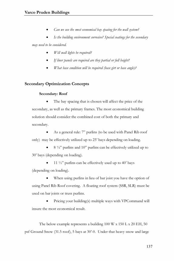
Varco Pruden Buildings
137
Can we use the most economical bay spacing for the wall system?
Is the building environment corrosive? Special coatings for the secondary
may need to be considered.
Will wall lights be required?
If liner panels are required are they partial or full height?
What base condition will be required (base girt or base angle)?
Secondary Optimization Concepts
Secondary: Roof
The bay spacing that is chosen will affect the price of the
secondary, as well as the primary frames. The most economical building
solution should consider the combined cost of both the primary and
secondary.
As a general rule: 7” purlins (to be used with Panel Rib roof
only) may be effectively utilized up to 25’ bays depending on loading.
8 ½” purlins and 10” purlins can be effectively utilized up to
30’ bays (depending on loading).
11 ½” purlins can be effectively used up to 40’ bays
(depending on loading).
When using purlins in lieu of bar joist you have the option of
using Panel Rib Roof covering. A floating roof system (SSR, SLR) must be
used on bar joists or truss purlins.
Pricing your building(s) multiple ways with VPCommand will
insure the most economical result.
The below example represents a building 100 W x 150 L x 20 EH, 50
psf Ground Snow (31.5 roof), 5 bays at 30’-0. Under that heavy snow and large
Systems Guide
138
bay the 8 ½” purlins required an intermediate spacing of 4’-0” while the 10” deep
purlins designed at the standard 5’-0” spacing. While costing slightly more, the
10” purlins yielded 24 less total purlins, thus saving on erection.
Your actual loading and geometry will affect the outcome of your price.
Run various scenarios to get the best results.
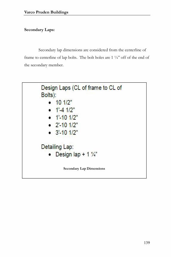
Varco Pruden Buildings
139
Secondary Laps:
Secondary lap dimensions are considered from the centerline of
frame to centerline of lap bolts. The bolt holes are 1 ¼” off of the end of
the secondary member.
Secondary Lap Dimensions
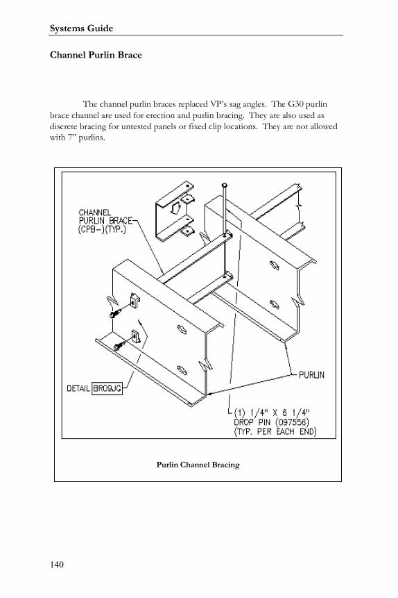
Systems Guide
140
Channel Purlin Brace
The channel purlin braces replaced VP’s sag angles. The G30 purlinbrace channel are used for erection and purlin bracing. They are also used asdiscrete bracing for untested panels or fixed clip locations. They are not allowedwith 7” purlins.
Purlin Channel Bracing

Varco Pruden Buildings
141
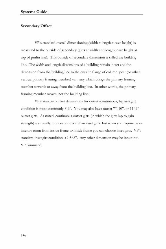
Systems Guide
142
Secondary Offset
VP’s standard overall dimensioning (width x length x eave height) is
measured to the outside of secondary (girts at width and length; eave height at
top of purlin line). This outside of secondary dimension is called the building
line. The width and length dimensions of a building remain intact and the
dimension from the building line to the outside flange of column, post (or other
vertical primary framing member) van vary which brings the primary framing
member towards or away from the building line. In other words, the primary
framing member moves, not the building line.
VP’s standard offset dimensions for outset (continuous, bypass) girt
condition is most commonly 8½”. You may also have outset 7”, 10”, or 11 ½”
outset girts. As noted, continuous outset girts (in which the girts lap to gain
strength) are usually more economical than inset girts, but when you require more
interior room from inside frame to inside frame you can choose inset girts. VP’s
standard inset girt condition is 1 5/8”. Any other dimension may be input into
VPCommand.
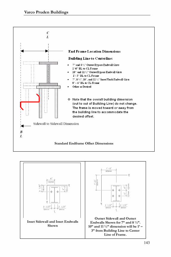
Varco Pruden Buildings
143
Notes:
Standard Endframe Offset Dimensions
Inset Sidewall and Inset EndwallsShown
Outset Sidewall and OutsetEndwalls Shown for 7” and 8 ½”.
10” and 11 ½” dimension will be 1’ –3” from Building Line to Center
Line of Frame.

Systems Guide
144
Typical Girt Spacing

Varco Pruden Buildings
145
Frame Offset: Dimension from Building Line to outside flange of Primary framingmember. For outset girst the dimension is the girt depth (7”, 8 ½” 10”, or 11 ½”);
for VP standard inset girts the dimension is 1 5/8”. Other frame offset
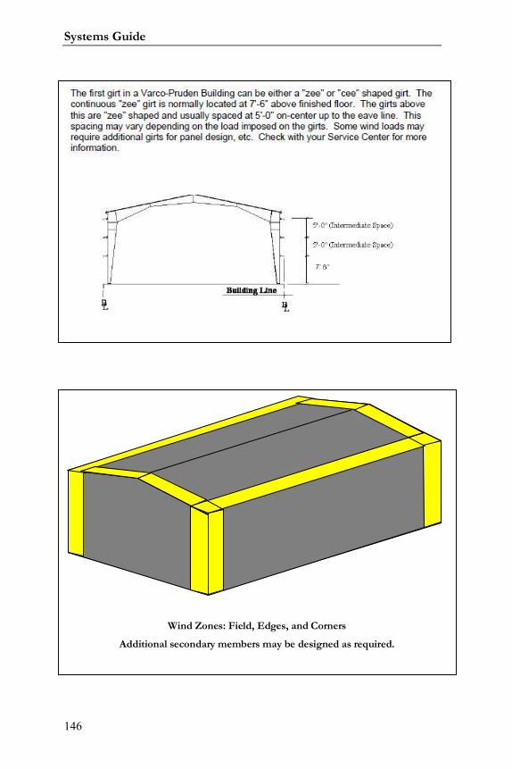
Systems Guide
146
Wind Zones: Field, Edges, and Corners
Additional secondary members may be designed as required.
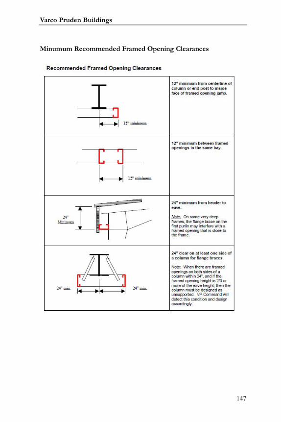
Varco Pruden Buildings
147
Minumum Recommended Framed Opening Clearances
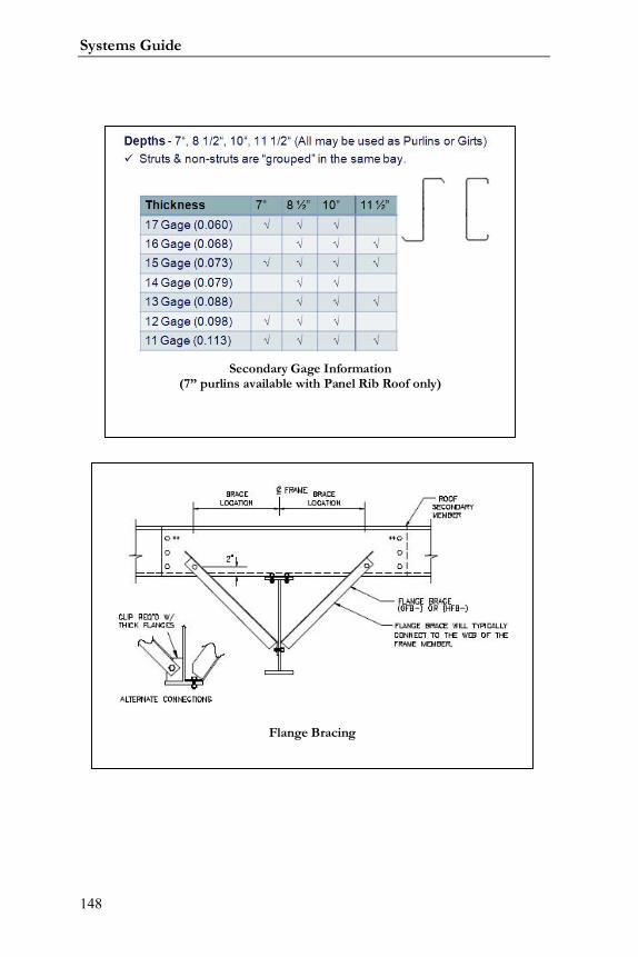
Systems Guide
148
Flange Bracing
Secondary Gage Information(7” purlins available with Panel Rib Roof only)

Varco Pruden Buildings
149
Notes:
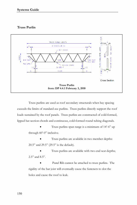
Systems Guide
150
Truss Purlin
Truss purlins are used as roof secondary structurals when bay spacing
exceeds the limits of standard zee purlins. Truss purlins directly support the roof
loads sustained by the roof panels. Truss purlins are constructed of cold-formed,
lipped hat section chords and continuous, cold-formed round tubing diagonals.
Truss purlins span range is a minimum of 14’-6” up
through 60’-0” inclusive.
Truss purlins are available in two member depths:
20.5” and 29.5” (29.5” is the default).
Truss purlins are available with two end seat depths;
2.5” and 8.5”.
Panel Rib cannot be attached to truss purlins. The
rigidity of the bar joist will eventually cause the fasteners to slot the
holes and cause the roof to leak.
Truss Purlinfrom: DP 4.4.1 February 3, 2010

Varco Pruden Buildings
151
Bar Joist
Note: Bar Joist over 60’ top cord cannot rely on SSR for top cord
support.
Bar Joist spans are effective from 40’ to 80’ bays.
Bar joist spans of 60’ or greater long span joists must be used.
Long span joist are considerably more expensive and should be avoided if
possible
Panel Rib cannot be attached to bar joist. The rigidity of the
bar joist will eventually cause the fasteners to slot the holes and cause the
roof to leak.
When you use Bar Joist you must use SSR, SLR, or composite
roof covering.
Secondary spacing can affect your insulation system for the
project.
When using bar joist the piping, ductwork, and wiring can be
installed within the bar joist system possibly providing additional clearance.
Ceiling Liner panels are not commonly used with bar joist
systems. If they are required VP can provide a composite roof system.
Systems Guide
152
FM (Factory Mutual) requirements
If you have FM requirements you will have to comply with special
conditions.
Strapping may be required in the end bays.
Additional purlins probably will be required in the edge zones,
corner zones, or possibly the entire roof.
VP has solutions for FM I-60, I-75, I-90, I-120 uplift
requirements with Standing Seam Roof panels (SSR). Contact your VP
Service Center for VP Command input and pricing assistance.
Contact the customer’s insurance carrier to verify minimum
requirements.
Roof Openings
RTU (Roof Top Unit) locations greatly affect their price.
Accurate location is critical for final pricing and design.
Locating RTUs close to an interior column, or close to the
haunch is the most economical location for a roof load.
Who is supplying the sub-framing for the roof top openings?
Are there any collateral loads applied to the roof secondary
(sprinkler, ceiling tiles, lighting, etc.)?
Roof Loading
Application of collateral or point loads on secondary members
requires exact locations to achieve accurate pricing.
When the collateral loading conditions of a portion of the
building differ substantially from the base collateral building load, then an
Varco Pruden Buildings
153
area representing the difference should be input into VP Command to
optimize the design.
o i.e., Project has 5 lb. collateral load, one area has 8 lb.
collateral load – define the area and add the 3 lbs. difference to
equal 8. (See Loading section for discussion)
The location of the specified area for a collateral load near a
frame line, or an interior column will lower the cost versus a location in
center of the bay.
Any special roof covering system impacts the design of the
secondary.
If you are using composite roof covering, panel by others, or
any non-VP roof covering system contact your VP Service Center.
Use Order Clarification form, section “Cladding not by VP”
information, forms are located in the Supplemental Price Book.
Miscellaneous Roof Secondary Concerns
Can we vary the bay spacing for the most economical
secondary framing?
Smaller endbays can save costs.
As a general rule, the endbay length is most effective at
approximately 85% of the interior bay length
Wider bays increase secondary costs
What is the building environment? Should we consider a
special coating for the secondary if we have a corrosive environment?
Galvanized coating may be less expensive than special painted,
i.e. epoxy or finish coat
Systems Guide
154
Secondary: Walls
Do you know the locations of the framed openings?
When applying the loading onto secondary members it is more
economical to be specific on location so costs can be optimized.
Framed opening locations can impact the location and type of
bracing.
Whenever possible use your sills and headers as the wall girts
for ease of erection.
Masonry walls can impact the design of the secondary.
o Is the wall load bearing?
o Who provides the support at the top of the masonry?
o What deflection criteria, has been specified for the
wall.
o Does VP supply wind beams?
o If VP supplies the wind beam, the required deflection
criteria should be specified. The wind beam may also be utilized to
transfer wind or seismic forces into the masonry or tilt. Utilize
flange braces from the masonry or tilt to the wind beam whenever
possible
Do you have a preference for the girt conditions (inset or
outset)?
Outset (continuous) girt design is the most economical at bay
spacing larger than 25’.
Bay Spacing will affect the cost of the wall secondary but there
is a greater impact on the roof secondary.
Continuous girts have higher erection costs than simple span
girts.
Do you have a preferred secondary profile (C or Zs)?
Varco Pruden Buildings
155
Standard VP wall secondary will be the “Z” profile. “C”
profile girts are simple span and will be more expensive than continuous
girts.
Do you need wall lights?
If you are using any wall lights, try to work within the system-
generated wall girt spacing to avoid adding girts for additional costs.
Do you need liner panels? If so, partial or full height?
If you are using any liner panel try to work within the system
generated wall girts spacing to avoid adding girt for additional costs.
What base condition do you need (base girt or base angle)?
A base girt will help with costs when a liner panel is going to
be used.
Two base angles will be less material cost, but the installation
of one base girt can be a savings on erection cost.
For choices of girt depths to use: check using 7” depth when
bay spacing is less than 25 feet. Be sure to compare pricing.
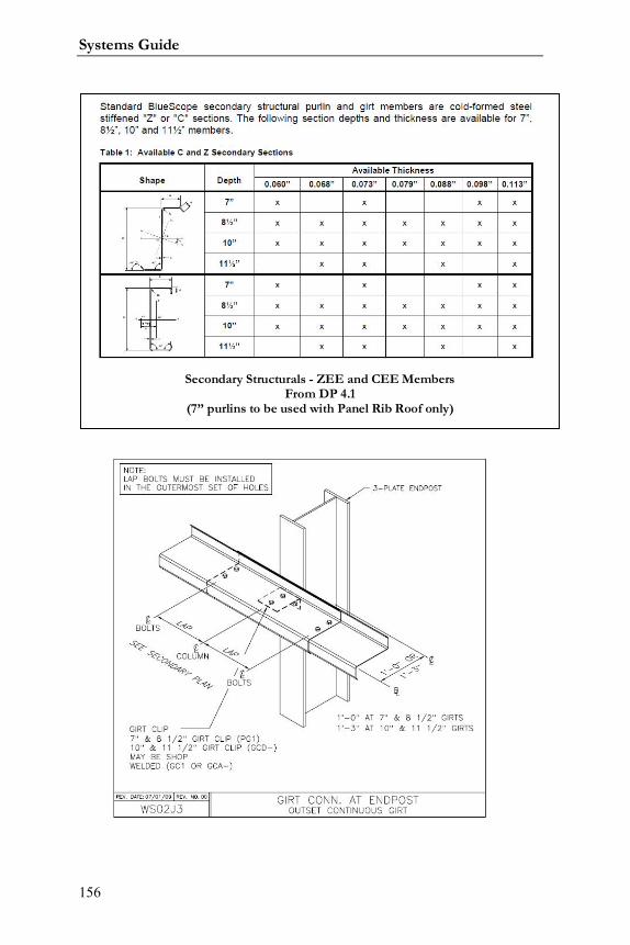
Systems Guide
156
Secondary Structurals - ZEE and CEE MembersFrom DP 4.1
(7” purlins to be used with Panel Rib Roof only)

Varco Pruden Buildings
157
Endframe Offset (Outset Girst Shown)See VP Command for Current Details
Secondary Bracing StrapsWall Panel Not By Varco Pruden
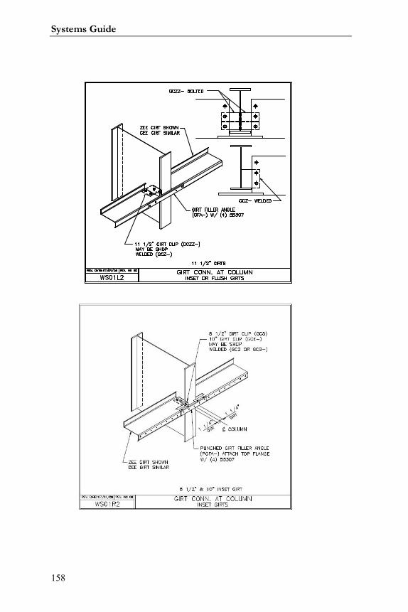
Systems Guide
158

Varco Pruden Buildings
159
Notes:

Systems Guide
160
Notes:

Varco Pruden Buildings
161
Systems Guide
162
Framed Openings
Framed openings are required in metal panel walls for doors, windows,
vents, louvers, etc.
What we want to determine in this section is the quantity and location
for all required wall openings.
Questions for the Customer
How many, what size and will framed openings be required?
What types of doors are required?
Will the doors be supplied by VP or others?
Are there any future or field located openings?
Framed Opening Optimization Concepts
Set the jamb extension to terminate into the first girt above the
header elevation. Every time a continuous girt is interrupted you add
material cost to the secondary members.
Accurately locating the opening(s) during estimating can save
you money in the end. If possible, do not locate an opening within 2’ of a
column centerline to allow for column flange brace.
When possible locate openings to allow rod bracing in
sidewall.
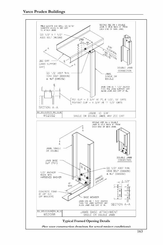
Varco Pruden Buildings
163
Typical Framed Opening Details
(See your construction drawings for actual project conditions)

Systems Guide
164
Notes:

Varco Pruden Buildings
165
Systems Guide
166
Openings
Openings are created in VPCommand when multiple buildings are
joined together – creating the opening(s) at the common wall(s). The default for
VPC is to remove all material (secondary, panel, insulation) so that one could
literally walk through the common area. You can put this material back in by
changing the parameters within the Openings folder of VPC. If you need to
remove material for items such as brick, block, masonry, glass, or actually open
you should create these at the “Covering” level(s) of VPC.
Questions for the Customer
Are there any areas of the building wall that are open to the elements (no
wall covering or secondary) such as covered loading docks?
Are there any building layouts that will be abutting each other?
Will there be covering or wall material on the common wall?
Opening Optimization Concepts
Areas that are open to the air will change the loading of the building and
will also be of importance to the mechanical equipment supplier if heating or air
movement is involved.
In VP Command, when buildings abut (having common wall regions),
the common wall is considered open unless it is changed to include common wall
material. This condition is important to understand when pricing the project
since loads are removed from the opening.
When putting material back in an opening, be aware that VP Command
has created an opening at each touching surface. Only change the parameters of
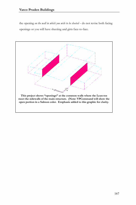
Varco Pruden Buildings
167
the opening on the wall in which you wish to be sheeted – do not revise both facing
openings or you will have sheeting and girts face-to-face.
This project shows “openings” at the common walls where the Lean-tosmeet the sidewalls of the main structure. (Note: VPCommand will show theopen portion in a Salmon color. Emphasis added to this graphic for clarity.

Systems Guide
168
Notes:

Varco Pruden Buildings
169

Systems Guide
170
Covering:
Varco Pruden Buildings
171
Covering
What is the most economical way to supply covering that meets the
owner’s requirements and the desired appearance? As noted in the previous
section on “Openings” if you require material that is not supplied by VP (brick,
glass, etc.) you should input these at the “Covering” level of VPC and not at the
“Openings” level.
Covering Questions for the Customer
Roof Covering
What type of roof covering is required for your building?: Panel Rib
(PR), Standing Seam Roof (SSR), Architectural profile (SLR-type), membrane?
Is a specific color / finish required?
Standard VP Color?
Special Color?
What is the roof pitch for the building? Panel Rib Roof minimum is
½:12; SSR and SLR minimums are ¼:12.
Wall Covering
What type of wall covering do you need for your building?: Architectural
profile, PR, Stranloc (available through VP Components), Vee-Rib, etc.?
Masonry?
Concrete Tilt Wall?
Stud Construction?
Systems Guide
172
Curtain Wall?
Is the wall a specific color / finish required?
Standard VP Color / finish?
Special Color / finish?
Covering Optimization Concepts
Most economical is the lightest gauge.
Utilize standard colors as much as possible.
Verify what warranties are required for the panel finishes.
KXL performance is better than SP. SP finish available with
Liner Panel only.
Controlling sheet lengths in order to eliminate a lap can be
cost effective, especially for Standing Seam Roof (SSR). Panel lengths over
48’ may require special freight.
Choose the most economical panel type for the building. For
example, Panel Rib roof may be an economical choice in lieu of SSR
depending on the use of the building
Trim packages vary with the panel.
Panels not by VP may increase the cost of secondary support
members and may require additional secondary strapping.
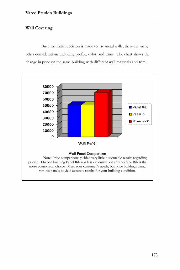
Varco Pruden Buildings
173
Wall Covering
Once the initial decision is made to use metal walls, there are many
other considerations including profile, color, and trims. The chart shows the
change in price on the same building with different wall materials and trim.
Wall Panel ComparisonNote: Price comparisons yielded very little discernable results regarding
pricing. On one building Panel Rib was less expensive, on another Vee Rib is themore economical choice. Meet your customer’s needs, but price buildings using
various panels to yield accurate results for your building condition.
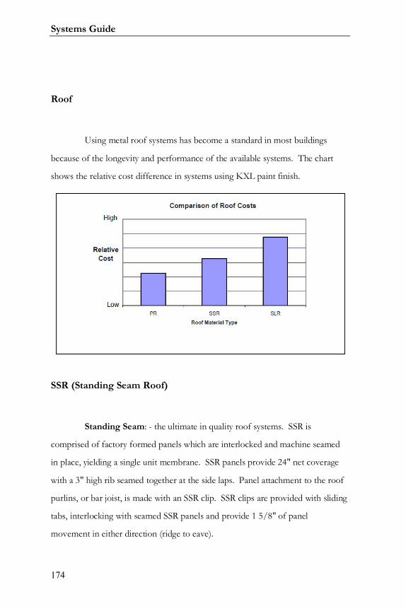
Systems Guide
174
Roof
Using metal roof systems has become a standard in most buildings
because of the longevity and performance of the available systems. The chart
shows the relative cost difference in systems using KXL paint finish.
SSR (Standing Seam Roof)
Standing Seam: - the ultimate in quality roof systems. SSR is
comprised of factory formed panels which are interlocked and machine seamed
in place, yielding a single unit membrane. SSR panels provide 24" net coverage
with a 3" high rib seamed together at the side laps. Panel attachment to the roof
purlins, or bar joist, is made with an SSR clip. SSR clips are provided with sliding
tabs, interlocking with seamed SSR panels and provide 1 5/8" of panel
movement in either direction (ridge to eave).
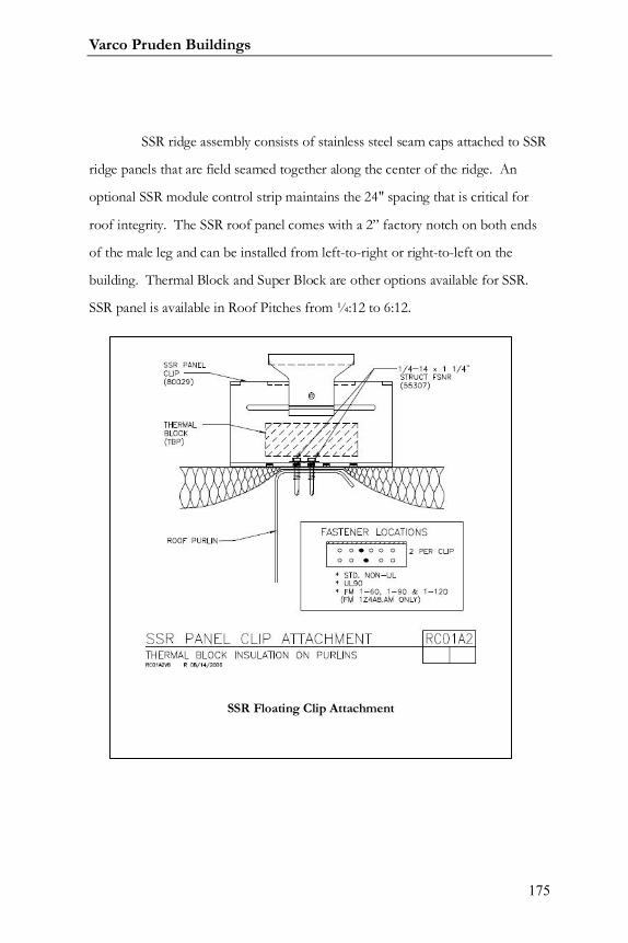
Varco Pruden Buildings
175
SSR ridge assembly consists of stainless steel seam caps attached to SSR
ridge panels that are field seamed together along the center of the ridge. An
optional SSR module control strip maintains the 24" spacing that is critical for
roof integrity. The SSR roof panel comes with a 2” factory notch on both ends
of the male leg and can be installed from left-to-right or right-to-left on the
building. Thermal Block and Super Block are other options available for SSR.
SSR panel is available in Roof Pitches from ¼:12 to 6:12.
SSR Floating Clip Attachment
Systems Guide
176
Panel Rib Roof
Panel Rib is well-established as an economical, quality roof. Standard
PR panels are Galvalume with self-drilling fasteners and 36" coverage. Primary
ribs are 13/16" high at 12" on-center with minor ribs in between. Side laps are
one full major rib utilizing an anti-capillary bead and a purlin bearing edge for
added support. PR roofs are available in 26, 24 or 22 gage. Galvalume, and
Kynar 500 (KXL) or Hylar 5000 paint finishes are also available. Roof pitch for
Panel Rib is ½:12 minimum with no maximum roof pitch.
SLR II
Span Loc Roof (SLR II)
SLR II: This roofing system is comprised of factory formed panels
which are interlocked and machine seamed in place - yielding a single unit
membrane. It is a visually appealing architectural standing seam roof system that
offers maximum design flexibility and aesthetics plus durability and is available in
a variety of KXL colors. SLR II panels provide 16” nominal coverage with a
vertical 2” high rib seamed together at the side laps. Panel attachment to the roof
purlins, or bar joist, is made with an SLR II clip. The clips are designed to
accommodate thermal expansion and contraction. Thermal Blocks are required
for SLR II.
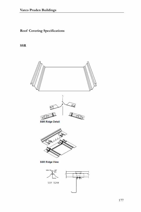
Varco Pruden Buildings
177
Roof Covering Specifications
SSR
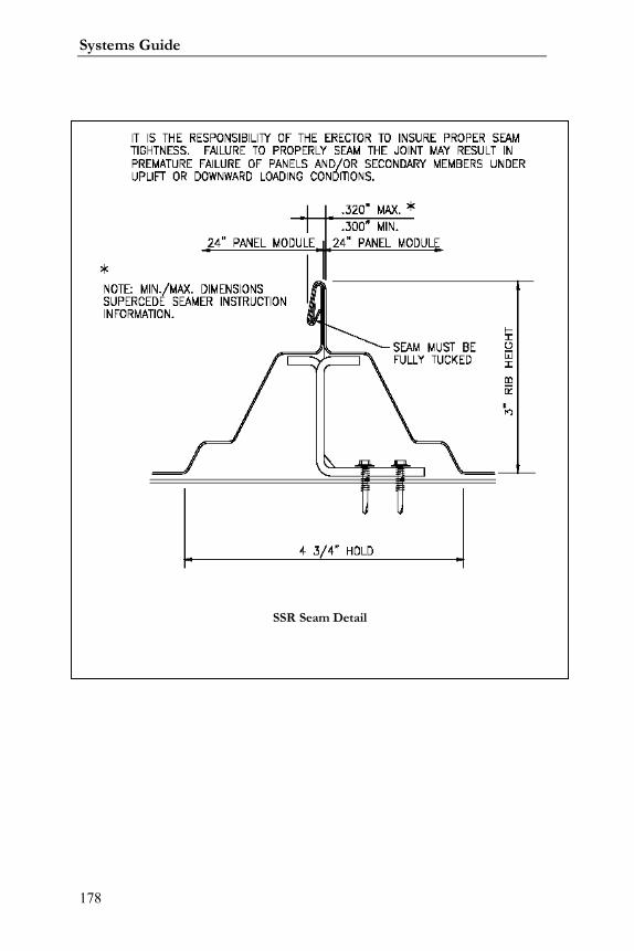
Systems Guide
178
SSR Seam Detail
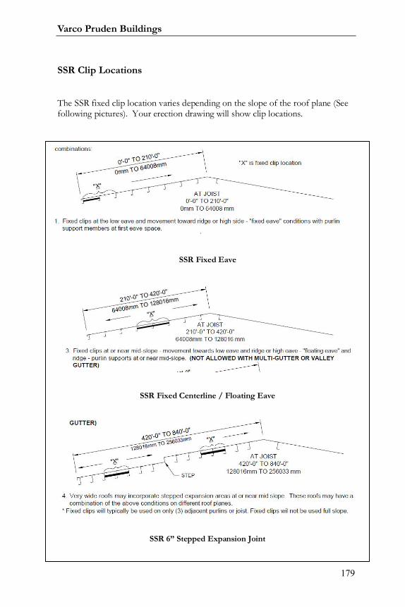
Varco Pruden Buildings
179
SSR Clip Locations
The SSR fixed clip location varies depending on the slope of the roof plane (Seefollowing pictures). Your erection drawing will show clip locations.
SSR Fixed Eave
SSR Fixed Centerline / Floating Eave
SSR 6” Stepped Expansion Joint
Systems Guide
180
SSR Feature SSR Benefit
The material used for
the SSR roof panel is 24 gage
ASTM a 446 Grade D, 50,000 PSI
yield strength steel. Optional
material is 22 gage ASTM A 466
Grade D, 50,000 PSI yield
strength steel.
The SSR panel is only
available with twenty year finishes
and coatings, Galvalume or KXL.
The rake and eave also have long
life KXL, 70% Kynar 500 or
Hylar 5000 coating.
Exposed fasteners are
self-drilling stainless capped with
bonded EPDM washer. Sealant,
tape mastic, and the closures used
meet or exceed the highest
industry standards.
The SSR roof system
can be provided with an optional
UL-90 uplift rating.
Several insulation
The standard materials
used are 33% thicker than the 26
gage materials often used on a
roof system. This allows for
greater structural strength of the
system. 22 gage material is
offered for even greater
environmental loads and roof
traffic.
The SSR roof system
uses only the highest quality
finishes and coatings available to
assure that the system maintains
the look and functionality for
which it was designed. Finishes
are warranted for 25 years.
Attention to the smallest
details assures a quality roof
system. All components used are
designed to create a long lasting
roof system of the highest quality.
The UL rating can
impact the insurance costs for
your building. The higher UL-90
rating can lower the insurance
cost for contents.
Varco Pruden Buildings
181
SSR Feature SSR Benefit
options are available: Fiberglass
blanket insulation can be up to 6"
in thickness or rigid board
insulation up to 3½" thick.
Optional "Superblock" or
"Thermal blocks" are available.
Staggered End Laps
Used on Purlins, Truss
Purlins or Bar Joist
The energy required to
heat and/or cool the building can
reduce the operating costs of the
structure by increasing the in-
place R-value of the insulating
system used. "Superblocks" or
"Thermal blocks” can increase the
insulation's thermal efficiency by
nearly 20%. In place R-19 can be
attained with the optional UL-90
uplift rating.
End laps are staggered 5’
standard with a 2” notch, which
produces less material to Seam.
This also makes the panel capable
of being sheeted in either
direction.
SSR can either be
installed on purlins, WideBay
Truss Purlins, or Bar Joist. Panel
Rib is only allowed to be installed
on Purlins.
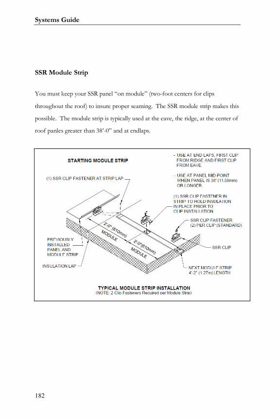
Systems Guide
182
SSR Module Strip
You must keep your SSR panel “on module” (two-foot centers for clips
throughout the roof) to insure proper seaming. The SSR module strip makes this
possible. The module strip is typically used at the eave, the ridge, at the center of
roof panles greater than 38’-0” and at endlaps.
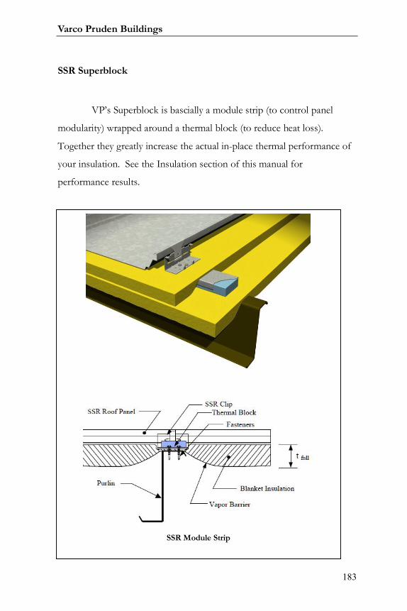
Varco Pruden Buildings
183
SSR Superblock
VP’s Superblock is bascially a module strip (to control panel
modularity) wrapped around a thermal block (to reduce heat loss).
Together they greatly increase the actual in-place thermal performance of
your insulation. See the Insulation section of this manual for
performance results.
SSR Module Strip
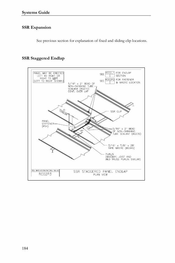
Systems Guide
184
SSR Expansion
See previous section for explanation of fixed and sliding clip locations.
SSR Staggered Endlap
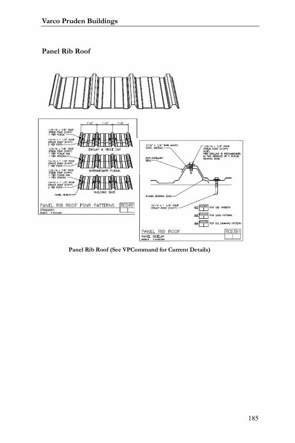
Varco Pruden Buildings
185
Panel Rib Roof
Panel Rib Roof (See VPCommand for Current Details)
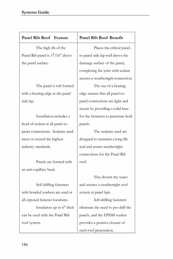
Systems Guide
186
Panel Rib Roof Feature Panel Rib Roof Benefit
The high rib of the
Panel Rib panel is 13/16" above
the panel surface.
The panel is roll formed
with a bearing edge at the panel
side lap.
Installation includes a
bead of sealant at all panel-to-
panel connections. Sealants used
meet or exceed the highest
industry standards.
Panels are formed with
an anti-capillary bead.
Self-drilling fasteners
with bonded washers are used at
all exposed fastener locations.
Insulation up to 6" thick
can be used with the Panel Rib
roof system.
Places the critical panel-
to-panel side lap well above the
drainage surface of the panel,
completing the joint with sealant
assures a weathertight connection.
The use of a bearing
edge assures that all panel-to-
panel connections are tight and
secure by providing a solid base
for the fasteners to penetrate both
panels.
The sealants used are
designed to maintain a long life
seal and assure weathertight
connections for the Panel Rib
roof.
This diverts the water
and assures a weathertight roof
system at panel laps.
Self-drilling fasteners
eliminate the need to pre-drill the
panels, and the EPDM washer
provides a positive closure of
each roof penetration.
Varco Pruden Buildings
187
Panel Rib Roof Feature Panel Rib Roof Benefit
Calculated "R" value of
19 can be attained with 6"
insulation.
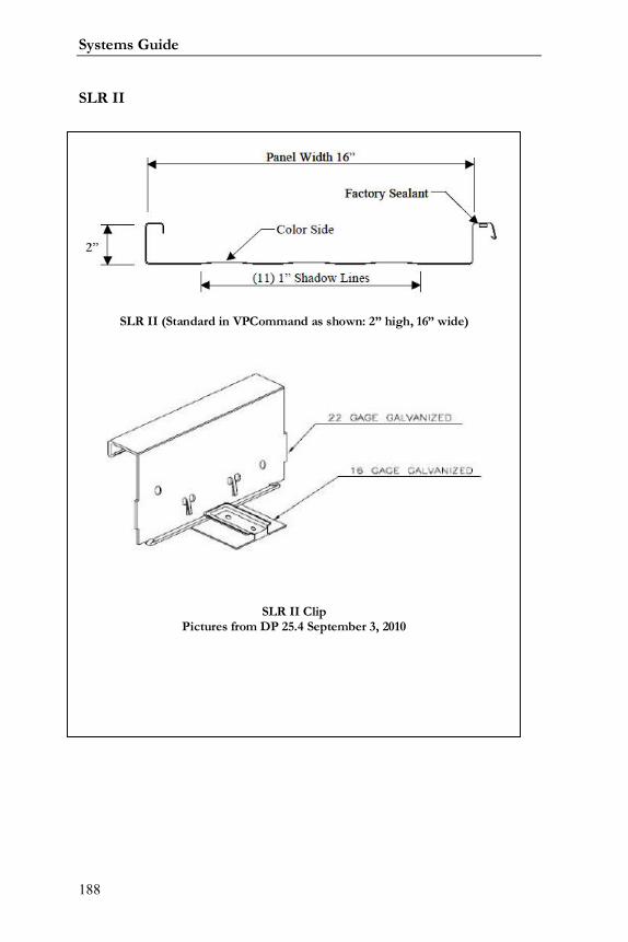
Systems Guide
188
SLR II
SLR II (Standard in VPCommand as shown: 2” high, 16” wide)
SLR II ClipPictures from DP 25.4 September 3, 2010
Varco Pruden Buildings
189
SLR II Feature SLR II Benefit
The SLR II roof is 2" in
height at the high rib.
The interlocking rib is at
a 70° bend that is formed using a
mechanical seaming tool.
The female leg of the
high rib has a factory applied
sealant.
Standard panels are
available in lengths up to 42’and
lengths up to 60’ with special
handling and permits.
The extended rib height
places the interlocking seam a full
2” above the drainage surface of
the panel, assuring
weathertightness at the panel
seams.
The use of the
mechanical seaming tool allows
for the seam to be completed
without overstressing the material.
This assures a tight seam along
the length of the interlocked high
rib.
This assures that the
correct amount of the proper
sealant is used in the high rib.
When the high rib is completed,
the sealant is compressed creating
a weathertight seal at all panel-to-
panel side laps.
The longer panel lengths
Systems Guide
190
SLR II Feature SLR II Benefit
Concealed two-pieced
clip system attaches the panel to
secondary structural and allows
for total thermal movement up to
1".
When panel endlaps are
required they are overlapped a full
5" with a staggered location off
the secondary members and a
panel stiffener. Two beads of
sealant are applied on the lower
panel.
The material used for
the SLR II roof panels are ASTM
A-792 Grade 50B, 50,000 PSI
yield strength steel, 24 gage for
SLR II.
The SLR II panel is only
provide for greater building spans
with fewer panel endlaps required
for the roof system.
The use of the concealed
clips assures that no roof
penetrations are required to
secure the panel to the secondary
structural members. This allows
the ridge flashing to absorb the
thermal expansion and
contraction of the roof system in
response to temperature change.
This assures that the
panel-to-panel endlaps are not
restricted in movement by a
secondary member. The
reinforcing plate assures that a
secure connection is made panel-
to-panel. The sealant assures that
the connection is weathertight.
The standard materials
used are 33% thicker than the 26
gage materials often used on a
roof system. This allows for
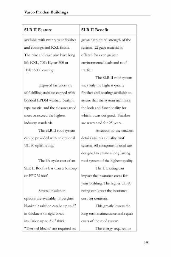
Varco Pruden Buildings
191
SLR II Feature SLR II Benefit
available with twenty year finishes
and coatings and KXL finish.
The rake and eave also have long
life KXL, 70% Kynar 500 or
Hylar 5000 coating.
Exposed fasteners are
self-drilling stainless capped with
bonded EPDM washer. Sealant,
tape mastic, and the closures used
meet or exceed the highest
industry standards.
The SLR II roof system
can be provided with an optional
UL-90 uplift rating.
The life cycle cost of an
SLR II Roof is less than a built-up
or EPDM roof.
Several insulation
options are available: Fiberglass
blanket insulation can be up to 6"
in thickness or rigid board
insulation up to 3½" thick.
"Thermal blocks" are required on
greater structural strength of the
system. 22 gage material is
offered for even greater
environmental loads and roof
traffic.
The SLR II roof system
uses only the highest quality
finishes and coatings available to
assure that the system maintains
the look and functionality for
which it was designed. Finishes
are warranted for 25 years.
Attention to the smallest
details assures a quality roof
system. All components used are
designed to create a long lasting
roof system of the highest quality.
The UL rating can
impact the insurance costs for
your building. The higher UL-90
rating can lower the insurance
cost for contents.
This greatly lowers the
long term maintenance and repair
costs of the roof system.
The energy required to

Systems Guide
192
SLR II Feature SLR II Benefit
SLR II. heat and/or cool the building can
be reduced the operating costs of
the structure by increasing the in-
place R-value of the insulating
system used. “Thermal blocks”
increase the insulation's thermal
efficiency by nearly 20%. In place
R-19 can be attained with the
optional UL-90 uplift rating.

Varco Pruden Buildings
193
Notes:
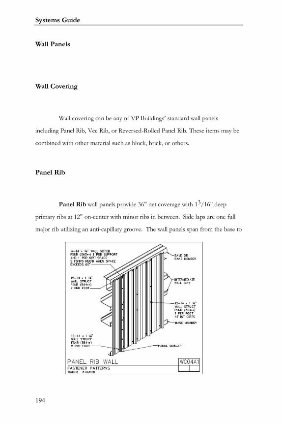
Systems Guide
194
Wall Panels
Wall Covering
Wall covering can be any of VP Buildings’ standard wall panels
including Panel Rib, Vee Rib, or Reversed-Rolled Panel Rib. These items may be
combined with other material such as block, brick, or others.
Panel Rib
Panel Rib wall panels provide 36" net coverage with 13/16" deep
primary ribs at 12" on-center with minor ribs in between. Side laps are one full
major rib utilizing an anti-capillary groove. The wall panels span from the base to

Varco Pruden Buildings
195
the eave (except where the eave exceeds 41'). Panel Rib panels offer a "crimped"
base and a "notch" at the eave (only available with PR roof) resulting in a better
seal and available savings through fewer required building materials (e.g., base
trim and closure strips). Panel Rib comes standard in KXL or Galvalume finish.
PR Wall Feature PR Wall Benefit
Base of panel can be
crimped or square cut.
Notched at the eave of
the panel when they are used with
a Panel Rib roof.
Panels are 36" wide with
lengths up to 41'.
Crimp eliminates the
need for base trim or notching
the slab. The crimped panel also
provides weather and rodent
protection. This saves both time
and cost during construction of
the project.
This provides a secure
fit between the wall and the roof
panel, and also can eliminate the
need for eave fascia and closures
to complete the building. This
feature saves both time and cost
during construction of the
buildings.
This allows more
coverage with fewer panel endlaps
and quicker to install.
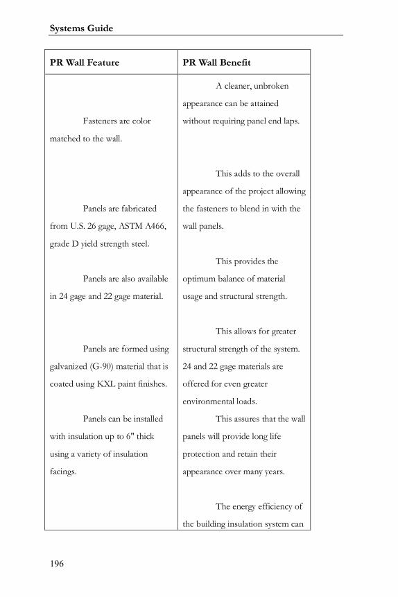
Systems Guide
196
PR Wall Feature PR Wall Benefit
Fasteners are color
matched to the wall.
Panels are fabricated
from U.S. 26 gage, ASTM A466,
grade D yield strength steel.
Panels are also available
in 24 gage and 22 gage material.
Panels are formed using
galvanized (G-90) material that is
coated using KXL paint finishes.
Panels can be installed
with insulation up to 6" thick
using a variety of insulation
facings.
A cleaner, unbroken
appearance can be attained
without requiring panel end laps.
This adds to the overall
appearance of the project allowing
the fasteners to blend in with the
wall panels.
This provides the
optimum balance of material
usage and structural strength.
This allows for greater
structural strength of the system.
24 and 22 gage materials are
offered for even greater
environmental loads.
This assures that the wall
panels will provide long life
protection and retain their
appearance over many years.
The energy efficiency of
the building insulation system can
Varco Pruden Buildings
197
PR Wall Feature PR Wall Benefit
be incorporated into the project
to lower the life cycle heating and
cooling expenses.

Systems Guide
198
Notes:
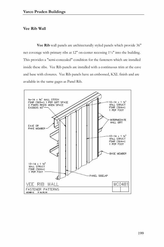
Varco Pruden Buildings
199
Vee Rib Wall
Vee Rib wall panels are architecturally styled panels which provide 36"
net coverage with primary ribs at 12" on-center recessing 1¼" into the building.
This provides a "semi-concealed" condition for the fasteners which are installed
inside these ribs. Vee Rib panels are installed with a continuous trim at the eave
and base with closures. Vee Rib panels have an embossed, KXL finish and are
available in the same gages as Panel Rib.
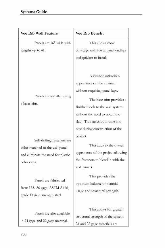
Systems Guide
200
Vee Rib Wall Feature Vee Rib Benefit
Panels are 36" wide with
lengths up to 41'.
Panels are installed using
a base trim.
Self-drilling fasteners are
color matched to the wall panel
and eliminate the need for plastic
color caps.
Panels are fabricated
from U.S. 26 gage, ASTM A466,
grade D yield strength steel.
Panels are also available
in 24 gage and 22 gage material.
This allows more
coverage with fewer panel endlaps
and quicker to install.
A cleaner, unbroken
appearance can be attained
without requiring panel laps.
The base trim provides a
finished look to the wall system
without the need to notch the
slab. This saves both time and
cost during construction of the
project.
This adds to the overall
appearance of the project allowing
the fasteners to blend in with the
wall panels.
This provides the
optimum balance of material
usage and structural strength.
This allows for greater
structural strength of the system.
24 and 22 gage materials are
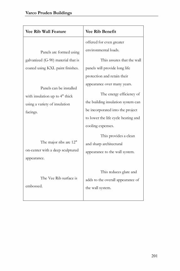
Varco Pruden Buildings
201
Vee Rib Wall Feature Vee Rib Benefit
Panels are formed using
galvanized (G-90) material that is
coated using KXL paint finishes.
Panels can be installed
with insulation up to 4" thick
using a variety of insulation
facings.
The major ribs are 12"
on-center with a deep sculptured
appearance.
The Vee Rib surface is
embossed.
offered for even greater
environmental loads.
This assures that the wall
panels will provide long life
protection and retain their
appearance over many years.
The energy efficiency of
the building insulation system can
be incorporated into the project
to lower the life cycle heating and
cooling expenses.
This provides a clean
and sharp architectural
appearance to the wall system.
This reduces glare and
adds to the overall appearance of
the wall system.
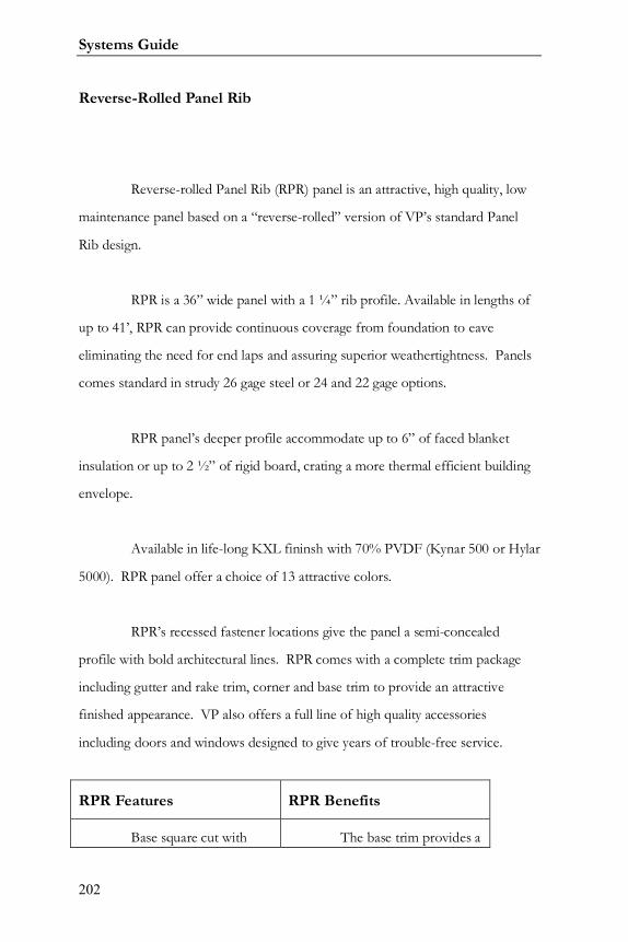
Systems Guide
202
Reverse-Rolled Panel Rib
Reverse-rolled Panel Rib (RPR) panel is an attractive, high quality, low
maintenance panel based on a “reverse-rolled” version of VP’s standard Panel
Rib design.
RPR is a 36” wide panel with a 1 ¼” rib profile. Available in lengths of
up to 41’, RPR can provide continuous coverage from foundation to eave
eliminating the need for end laps and assuring superior weathertightness. Panels
comes standard in strudy 26 gage steel or 24 and 22 gage options.
RPR panel’s deeper profile accommodate up to 6” of faced blanket
insulation or up to 2 ½” of rigid board, crating a more thermal efficient building
envelope.
Available in life-long KXL fininsh with 70% PVDF (Kynar 500 or Hylar
5000). RPR panel offer a choice of 13 attractive colors.
RPR’s recessed fastener locations give the panel a semi-concealed
profile with bold architectural lines. RPR comes with a complete trim package
including gutter and rake trim, corner and base trim to provide an attractive
finished appearance. VP also offers a full line of high quality accessories
including doors and windows designed to give years of trouble-free service.
RPR Features RPR Benefits
Base square cut with The base trim provides a
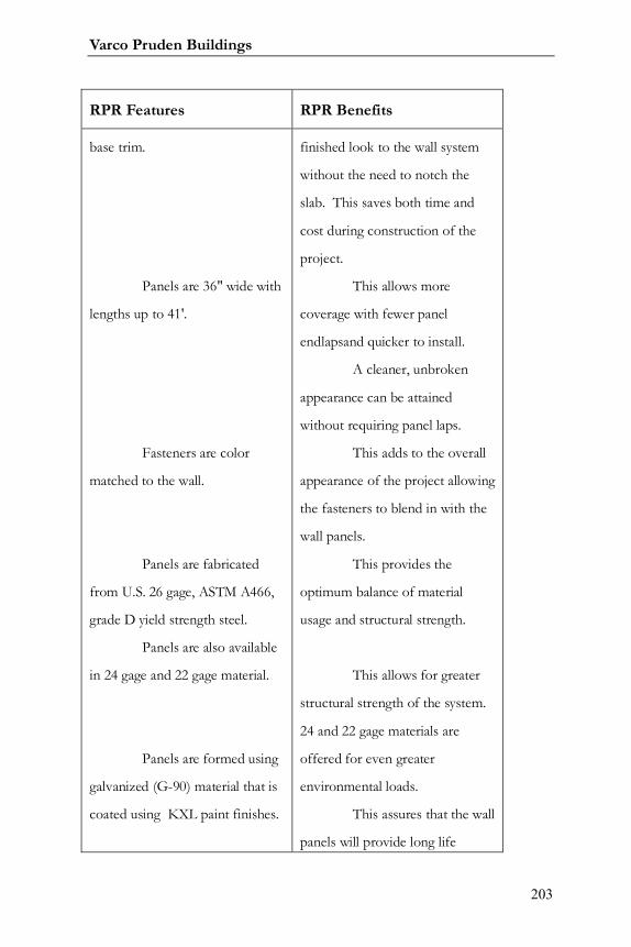
Varco Pruden Buildings
203
RPR Features RPR Benefits
base trim.
Panels are 36" wide with
lengths up to 41'.
Fasteners are color
matched to the wall.
Panels are fabricated
from U.S. 26 gage, ASTM A466,
grade D yield strength steel.
Panels are also available
in 24 gage and 22 gage material.
Panels are formed using
galvanized (G-90) material that is
coated using KXL paint finishes.
finished look to the wall system
without the need to notch the
slab. This saves both time and
cost during construction of the
project.
This allows more
coverage with fewer panel
endlapsand quicker to install.
A cleaner, unbroken
appearance can be attained
without requiring panel laps.
This adds to the overall
appearance of the project allowing
the fasteners to blend in with the
wall panels.
This provides the
optimum balance of material
usage and structural strength.
This allows for greater
structural strength of the system.
24 and 22 gage materials are
offered for even greater
environmental loads.
This assures that the wall
panels will provide long life
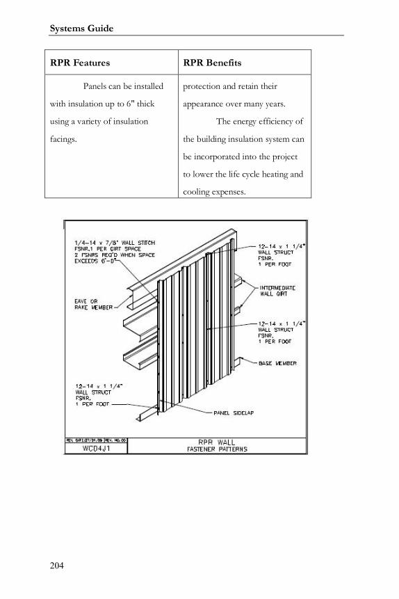
Systems Guide
204
RPR Features RPR Benefits
Panels can be installed
with insulation up to 6" thick
using a variety of insulation
facings.
protection and retain their
appearance over many years.
The energy efficiency of
the building insulation system can
be incorporated into the project
to lower the life cycle heating and
cooling expenses.
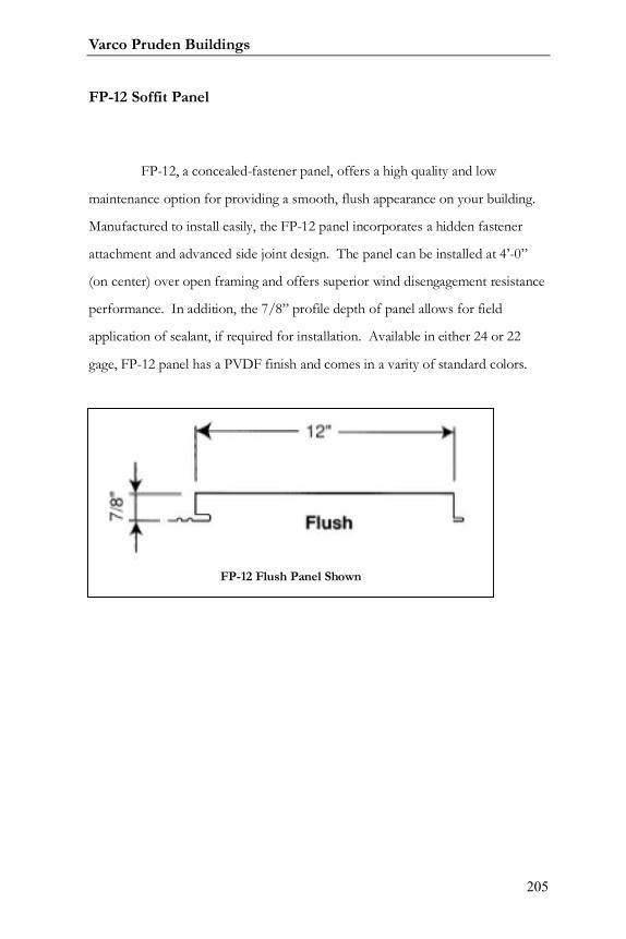
Varco Pruden Buildings
205
FP-12 Soffit Panel
FP-12, a concealed-fastener panel, offers a high quality and low
maintenance option for providing a smooth, flush appearance on your building.
Manufactured to install easily, the FP-12 panel incorporates a hidden fastener
attachment and advanced side joint design. The panel can be installed at 4’-0”
(on center) over open framing and offers superior wind disengagement resistance
performance. In addition, the 7/8” profile depth of panel allows for field
application of sealant, if required for installation. Available in either 24 or 22
gage, FP-12 panel has a PVDF finish and comes in a varity of standard colors.
FP-12 Flush Panel Shown
Systems Guide
206
Texture Clad
The stucco-like appearance of TextureClad will satisfy most local
building ordinances that prohibit other metal wall panel applications. The panels
are durable and provide protection from UV rays.
Each TextureClad panel is manufactured from 20 gauge-galvanized
steel. Panel width is 16” with a 1 ½” flange on one end and a ½” lock flange on
the other edge. The top flange is finished with a double 90-degree flange and the
bottom is finished with a single 90-degree flange. Formed ends allow the panel to
nest end-to-end for stacking up a vertical wall, allowing for taller elevation
applications. Installation of panel over weatherproof membrane is
recommended.
Factory applied textured finish is composed of a fiber reinforced
poly/aggregate composition, which adheres to the pre-painted panel surface. The
panels are available in a variety of colors. TextureClad comes with a 10-year
warranty for the panel and finish. The panel is available in four depths 2”, 2.5”,
3”, and 4”.
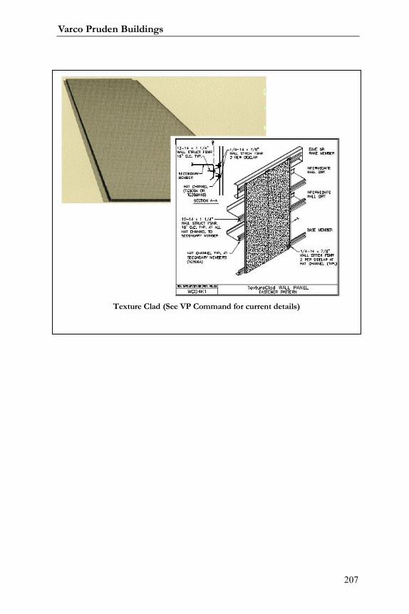
Varco Pruden Buildings
207
Texture Clad (See VP Command for current details)
Systems Guide
208
Thermal Clad
ThermalClad panels are a one-piece construction composed of panel
each side with a middle polyurethane foam core. The advanced polyurethane
core provides enhanced insulation values that significantly lower heating and
cooling costs. Concealed attachment with clips and fasteners at the side joint of
the panel offer a clean high profile appearance.

Varco Pruden Buildings
209
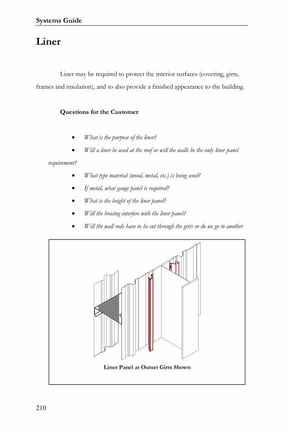
Systems Guide
210
Liner
Liner may be required to protect the interior surfaces (covering, girts,
frames and insulation), and to also provide a finished appearance to the building.
Questions for the Customer
What is the purpose of the liner?
Will a liner be used at the roof or will the walls be the only liner panel
requirement?
What type material (wood, metal, etc.) is being used?
If metal, what gauge panel is required?
What is the height of the liner panel?
Will the bracing interfere with the liner panel?
Will the wall rods have to be cut through the girts or do we go to another
Liner Panel at Outset Girts Shown
Varco Pruden Buildings
211
type of bracing?
Will flange braces fastened through the liner panel be allowed? Removal
of flange braces will make the columns or rafters unsupported which will make them more
expensive. If you only require no flange bracing at a partial height liner condition, state so,
and allow flange bracing above for more economical framing.
Liner Panel Optimization Concepts
Utilize standard colors as much as possible.
Verify what warranties are required for the panel finishes. Use
SP finish as much as possible.

Systems Guide
212
Notes:

Varco Pruden Buildings
213
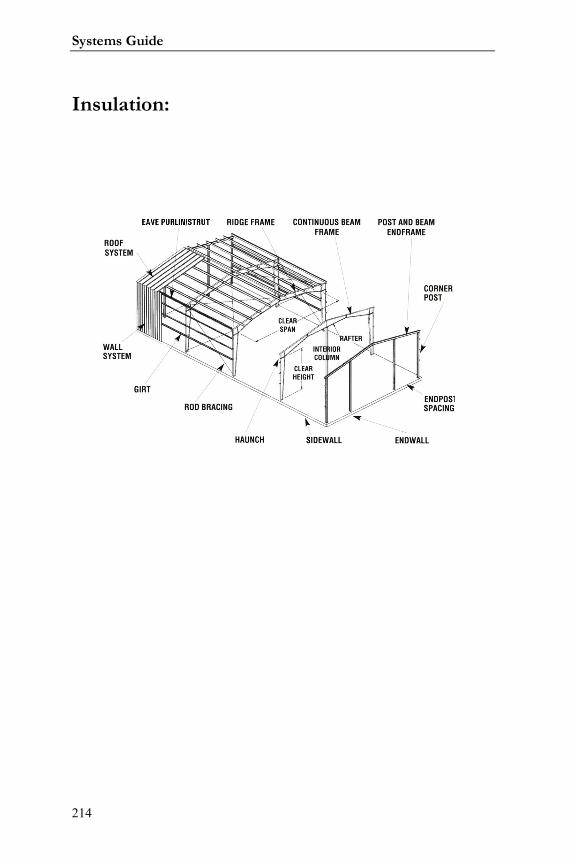
Systems Guide
214
Insulation:
Varco Pruden Buildings
215
Insulation2
What Does Building System Insulation Do?3
Controls Heat flow:
Metal building insulation acts as a barrier to slow down the movement
of heat, keeping it inside the building in winter and outside the building in
summer. By controlling the rate of heat transfer through the building, insulation
reduces energy consumption, resulting in lower fuel bills and a cleaner
environment.
Prevents Condensation:
Metal building insulation with a vapor retarder facing limits the
passage of water vapor and prevents it from condensing within the
insulation or on the interior surfaces of the building.
Controls Noise:
Metal building insulation greatly reduces the level of both exterior
and interior noise by preventing transmission of exterior sounds to the
interior of the building and absorbing reverberating sounds within the
building.
Increases Lighting Efficiency:
The laminated facings on metal building insulation provide a
bright, attractive wall and ceiling treatment that acts as a reflector to
increase lighting efficiency.
2 By David Hales3 From North American Insulation Manufacturers Association (NAIMA) Pub. No.MB316 8/06
Systems Guide
216
The complex, technical process of building most any permanent
structure requires attention to detail from concept to the final entry on a punch
list. Specifications are written to meet the expectations of the owner, as well as
comply with building codes and to protect the interest of a number of parties,
including the architects, engineers, contractors, vendors, lending institutions,
government agencies, and, of course, the owners.
One crucial aspect covered by the specifications is the heating and
cooling of the structure. An effective insulation solution that addresses the initial
cost and long term operating expenses associated with the building’s life cycle
must be met.
When ambiguous specifications for the design of the thermal envelope
are misinterpreted, both initial construction and annual operating costs may be
higher than necessary. Given the increased emphasis on energy conservation, as
well as the rising cost of energy and broader acceptance of ASHRAE standards
over the past decade, there is keen interest in providing cost-effective insulation
methods for the thermal envelopes of buildings. Clear and concise thermal
performance specifications will help ensure that buildings will meet energy usage
expectations and, in turn, save money. Since the ASHRAE standards require a
building’s insulation system to generate an in-place U-value, the past methods of
specifying and installing insulation must be challenged and changed throughout
the industry to comply with the new expectations.
Most misinterpretation of insulation specifications arises when wall and
ceiling manufacturers fail to test their product as installed. This can seriously
affect the heating and cooling of a building. It is not enough to test the insulation
in a standard environment; it must be tested as actually installed on the building.
This is commonly referred to as an in-place testing method.
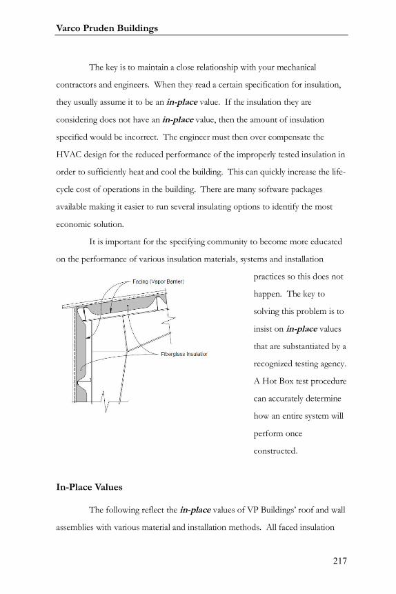
Varco Pruden Buildings
217
The key is to maintain a close relationship with your mechanical
contractors and engineers. When they read a certain specification for insulation,
they usually assume it to be an in-place value. If the insulation they are
considering does not have an in-place value, then the amount of insulation
specified would be incorrect. The engineer must then over compensate the
HVAC design for the reduced performance of the improperly tested insulation in
order to sufficiently heat and cool the building. This can quickly increase the life-
cycle cost of operations in the building. There are many software packages
available making it easier to run several insulating options to identify the most
economic solution.
It is important for the specifying community to become more educated
on the performance of various insulation materials, systems and installation
practices so this does not
happen. The key to
solving this problem is to
insist on in-place values
that are substantiated by a
recognized testing agency.
A Hot Box test procedure
can accurately determine
how an entire system will
perform once
constructed.
In-Place Values
The following reflect the in-place values of VP Buildings’ roof and wall
assemblies with various material and installation methods. All faced insulation
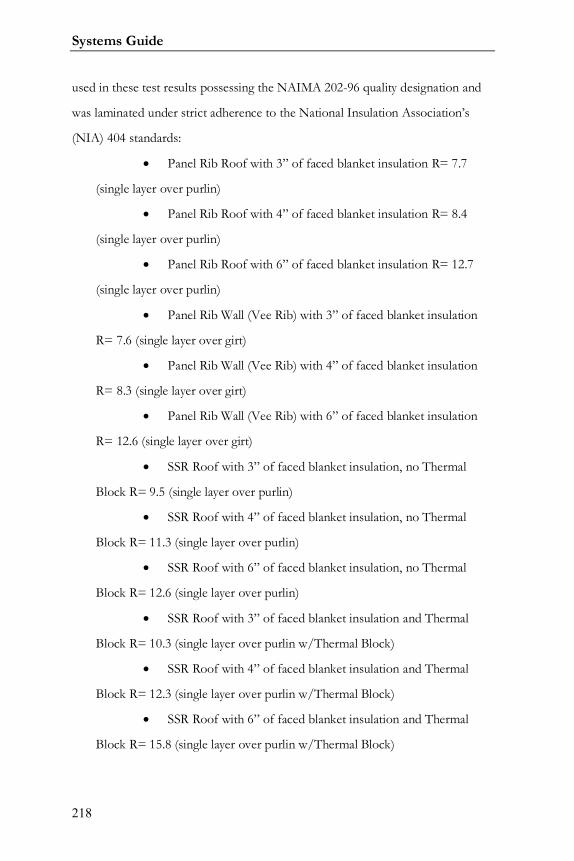
Systems Guide
218
used in these test results possessing the NAIMA 202-96 quality designation and
was laminated under strict adherence to the National Insulation Association’s
(NIA) 404 standards:
Panel Rib Roof with 3” of faced blanket insulation R= 7.7
(single layer over purlin)
Panel Rib Roof with 4” of faced blanket insulation R= 8.4
(single layer over purlin)
Panel Rib Roof with 6” of faced blanket insulation R= 12.7
(single layer over purlin)
Panel Rib Wall (Vee Rib) with 3” of faced blanket insulation
R= 7.6 (single layer over girt)
Panel Rib Wall (Vee Rib) with 4” of faced blanket insulation
R= 8.3 (single layer over girt)
Panel Rib Wall (Vee Rib) with 6” of faced blanket insulation
R= 12.6 (single layer over girt)
SSR Roof with 3” of faced blanket insulation, no Thermal
Block R= 9.5 (single layer over purlin)
SSR Roof with 4” of faced blanket insulation, no Thermal
Block R= 11.3 (single layer over purlin)
SSR Roof with 6” of faced blanket insulation, no Thermal
Block R= 12.6 (single layer over purlin)
SSR Roof with 3” of faced blanket insulation and Thermal
Block R= 10.3 (single layer over purlin w/Thermal Block)
SSR Roof with 4” of faced blanket insulation and Thermal
Block R= 12.3 (single layer over purlin w/Thermal Block)
SSR Roof with 6” of faced blanket insulation and Thermal
Block R= 15.8 (single layer over purlin w/Thermal Block)
Varco Pruden Buildings
219
SSR Roof with 6” of blanket insulation and a 3” SuperBlock
R= 19.0 (4” faced layer over purlin, and 2” unfaced layer over SuperBlock)
SSR Roof with 7” of blanket insulation and a 3” SuperBlock
R= 22.8 (4” faced layer over purlin, and 3” unfaced layer over SuperBlock)
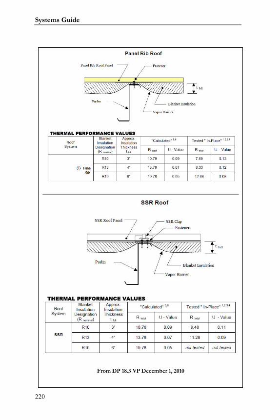
Systems Guide
220
From DP 18.3 VP December 1, 2010
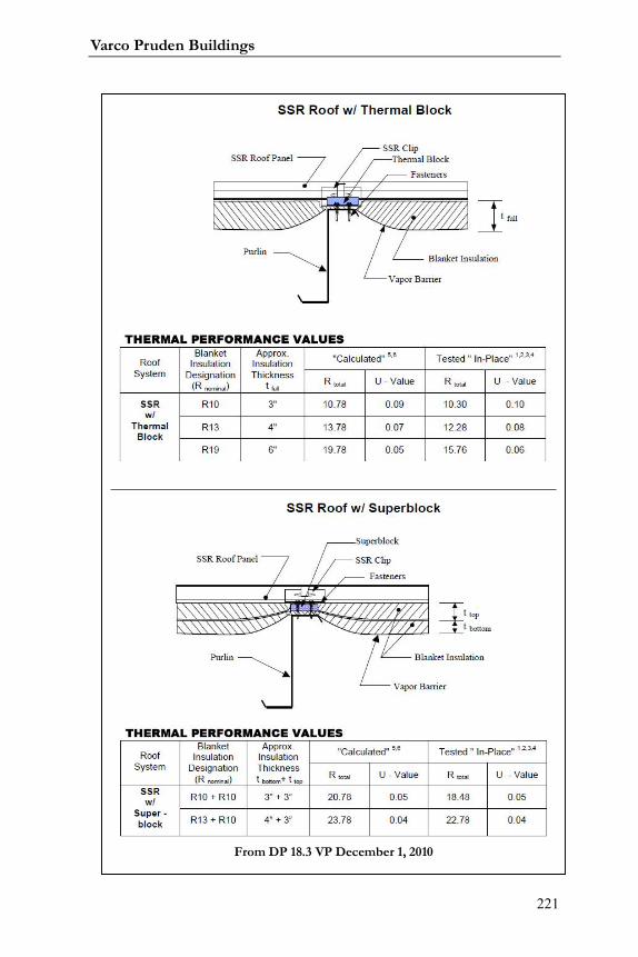
Varco Pruden Buildings
221
From DP 18.3 VP December 1, 2010

Systems Guide
222
Another important factor when installing insulation is to determine the
proper vapor retarder that needs to be applied. The perm rating associated with
the facing indicates the rate of vapor transmission through the material. The best
rating in the metal building industry is a .02. It provides a significant vapor
retarder that is required to keep the insulation dry and capable of performing at
an optimum level.
Insulation Considerations
Here is a checklist of things to remember when working on future
projects:
From DP 18.3 VP December 1, 2010
Varco Pruden Buildings
223
o Understand the code requirements for each project. Just because you erect
several buildings in the same geographical market does not mean that they
have the same insulation requirements.
o Make sure the insulation is specified to represent an in-place value that is
supported by ASTM Hot Box testing procedures.
o Challenge the insulation specifications that are vague and ambiguous.
o Insist on using fiberglass insulation that is manufactured, laminated and is
certified to possess the NAIMA 202-96 and NIA 404 quality standards.
o Consider VP’s 6” SuperBlock system when installing roof insulation. It has
a tested in-place R-19 value and is protected by U.S. Patents.
o A seven-inch system is also available. It has a tested in-place value of 22.8
and meets ASHRAE roof standards for all states except some locations in
Alaska.
o “R” and “U” values are the reciprocal of each other.
o Contact your VP District Manager or Laminator to assist you in
understanding the various insulating options through the VP Buildings
Insulation program.
VII. Building Energy Conservation4
7.1 General
Energy conservation is an important consideration for building owners
and designers that is regulated through local and national codes. These codes are
4 Section VII Building Energy Conservation from: Metal Building Systems Manual. 2006.Cleveland, Ohio.
Systems Guide
224
evolving, becoming more stringent, and being better enforced. Understanding
energy conservation requires a basic understanding of the theory, terms, and
construction practices. Good planning and proper use of energy conservation
principles will pay off in long-term economic gains for the owner, comfort for
the occupants and reductions in maintenance and modification to the building as
it ages.
7.1.1 Heat Transfer Fundamentals
Heat transfer is the term commonly used to indicate the movement of
heat (energy) from one region to another. Minimizing heat transfer is the role
that insulating materials play in conserving energy. The driving force for heat
transfer is the difference in temperature between two regions, or surfaces, and
will occur in a direction from hot to cold. The three basic mechanisms of heat
transfer are as follows:
1) Conduction - the process by which heat will transfer through a solid
material. Heat will transfer through the material from hot to cold by means of
molecular contact.
2) Convection - the transfer of heat by means of a moving fluid such as
air or water. Heat is picked up by a moving fluid and transported to another
region.
3) Radiation - the transfer of heat by means of electromagnetic waves.
7.1.2 Measurement of Heat Transfer
The amount of heat transferred is measured in British Thermal Units
(BTU). One BTU is equivalent to the amount of energy required to raise one
Varco Pruden Buildings
225
pound of water by one degree Fahrenheit (F). Several interrelated properties are
used to measure the ability of a material to permit heat flow through it.
Thermal conductance (C) is a measure of the rate (measured in BTU's
per hour) that heat will flow through an insulating material. Materials that have
lower conductance values will allow less heat to flow through them.
Thermal resistance (R) is a measure of a material's ability to resist the
passage of heat. Thermal resistance is often expressed using the common term
“R-value”. Materials with higher resistance values allow less heat to flow through
them. Thermal resistance is the reciprocal of the thermal conductance. For
multi-layer systems, the total resistance (Rt) is the sum of the individual resistance
of each layer.
Thermal transmittance (U) is the total rate that heat will flow through
a given assembly including the effects of surface air film resistances. Thermal
transmittance is often expressed using the common term “U-value” or “U-
factor”. A lower U-value indicates that less heat will flow through an assembly.
Thermal transmittance (U) is the reciprocal of the total thermal resistance, Rt.
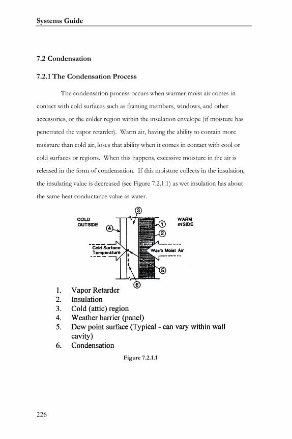
Systems Guide
226
7.2 Condensation
7.2.1 The Condensation Process
The condensation process occurs when warmer moist air comes in
contact with cold surfaces such as framing members, windows, and other
accessories, or the colder region within the insulation envelope (if moisture has
penetrated the vapor retarder). Warm air, having the ability to contain more
moisture than cold air, loses that ability when it comes in contact with cool or
cold surfaces or regions. When this happens, excessive moisture in the air is
released in the form of condensation. If this moisture collects in the insulation,
the insulating value is decreased (see Figure 7.2.1.1) as wet insulation has about
the same heat conductance value as water.
Figure 7.2.1.1
Varco Pruden Buildings
227
Method of Condensation
In dealing with condensation, air may be considered to be a mixture of
two gasses - dry air and water vapor. One thousand cubic feet of air at 75° F can
hold up to 1.4 pints of water. At 45° F, the same volume of air can hold only 0.5
pints. Relative humidity is a percentage measurement of the amount of water
vapor present in the air in relation to the amount it is capable of holding at that
temperature. For example, 50% relative humidity indicates the air is carrying
one-half of the maximum amount of moisture that it is capable of containing at
the given temperature. Cold, outside air is usually much drier than warm inside
air. Therefore, the indoor relative humidity can be lowered by bringing in outside
air to mix with and dilute the moist inside air. At 100% relative humidity, the air
is “saturated.” The temperature at which the air is saturated and can no longer
hold the moisture is called the dew point temperature (see Table 7.2.4.1 for more
information). Whenever air temperature drops below its dew point, excess
moisture will be released in the form of condensation. Condensation problems
are most likely to occur in climates where temperatures frequently dip to 35° F or
colder over an extended period of time.
7.2.2 Condensation Control
Two things must be present for condensation to occur: warm moist air,
and cool surface temperatures below the dew point. The proper control of these
two factors can minimize condensation. In metal building systems, we are
concerned with two different areas or locations: visible condensation which
occurs on surfaces below dew point temperatures; and concealed condensation
which occurs when moisture has passed into interior regions and then condenses
on a surface below dew point temperature.
Systems Guide
228
7.2.2.1 Visible Condensation
To effectively control visible condensation, it is necessary to reduce the
cold surface areas where condensation may occur. It is also important to
minimize the air moisture content within a building by the use of properly
designed ventilating systems.
7.2.2.2 Concealed Condensation
Concealed condensation is the most difficult to deal with and can be the
most damaging to any kind of structure. This type of condensation may be
controlled in metal buildings by the proper use of vapor retarders and by
minimizing moisture content within the building by proper ventilation.
Additional condensation control can be accomplished by venting the cavities of
the walls and roof.
7.2.3 Vapor Retarders
A vapor retarder is used to inhibit the passage of warmer moist air into
the inner regions of the roof or wall system. The proper selection and installation
of the vapor retarder can help control condensation problems in a building.
Vapor retarders are rated by the amount of moisture that can pass through them.
The lower this rating, called a perm rating, the less vapor transmission will occur
and the more effective the vapor retarder will be. There are various types of
vapor retarders available, such as:
1. Structural Membranes, including rigid steel sheets or other
impermeable material.
2. Flexible Membranes, such as foils, coated papers, or plastic films.
Usually, these membranes are rated by “perm” of 1.0 or less, per ASTM E-96.
Varco Pruden Buildings
229
(The most familiar to the metal building industry are the membrane retarders
laminated to fiberglass blanket insulation). Plain white vinyl with a perm rating of
1.0 is not an effective vapor retarder, especially in buildings with a high relative
humidity.
3. Coating Membranes, which includes paints.
Proper Sealing of the Vapor Retarder
1. When installing either a membrane type or structural type,
make sure that all seams, laps and joints are properly sealed. Sealing a vapor
retarder may be achieved by gluing, taping, overlapping, or stapling
according to the insulation supplier’s recommendations.
2. In the case of a membrane type retarder, make sure that any
punctures or tears in the material are repaired.

Systems Guide
230
Notes:

Varco Pruden Buildings
231

Systems Guide
232
Trim:

Varco Pruden Buildings
233
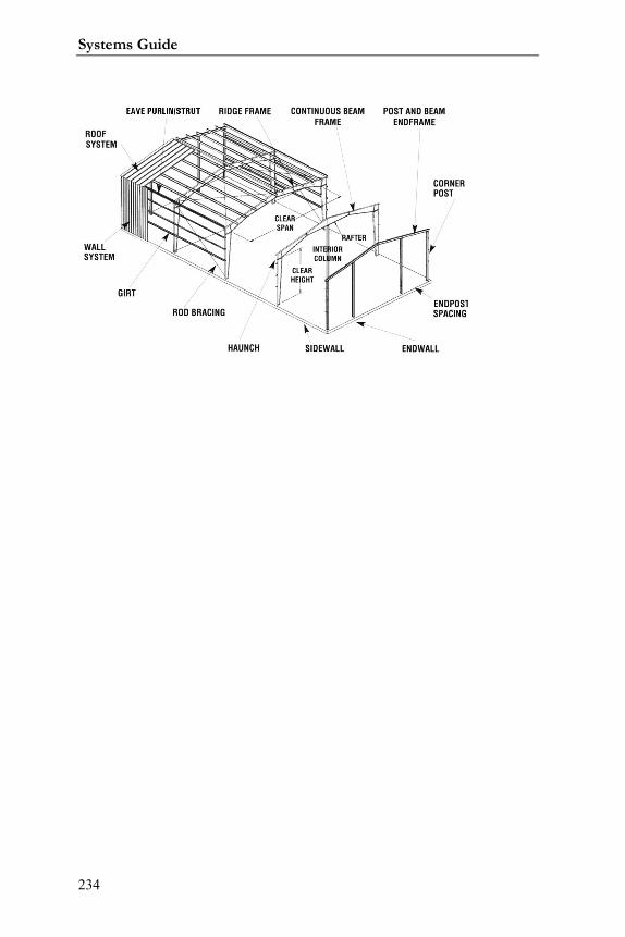
Systems Guide
234
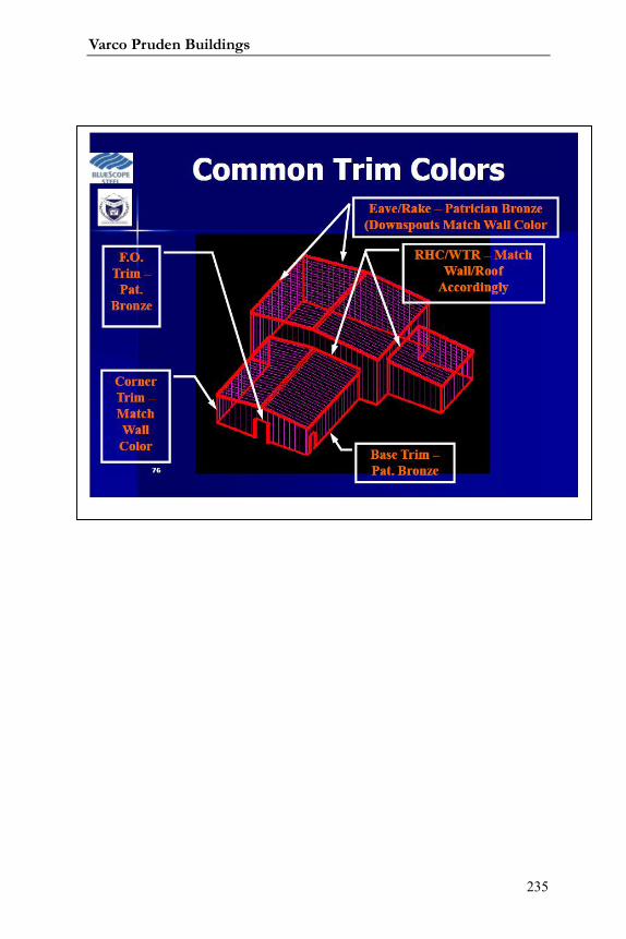
Varco Pruden Buildings
235
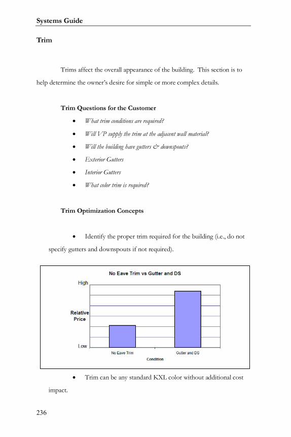
Systems Guide
236
Trim
Trims affect the overall appearance of the building. This section is to
help determine the owner’s desire for simple or more complex details.
Trim Questions for the Customer
What trim conditions are required?
Will VP supply the trim at the adjacent wall material?
Will the building have gutters & downspouts?
Exterior Gutters
Interior Gutters
What color trim is required?
Trim Optimization Concepts
Identify the proper trim required for the building (i.e., do not
specify gutters and downspouts if not required).
Trim can be any standard KXL color without additional cost
impact.
Varco Pruden Buildings
237
If panels are not by VP, identify who will supply the trim
conditions.
If SMACNA5 trim detailing is required, it is available from
AEP-Span at an additional cost.
Avoid interior gutter if possible.
5 SMACNA – Sheet Metal and Air Conditioning Contractor’s National Association

Systems Guide
238
Notes:
Varco Pruden Buildings
239
Trim Conditions Details
The following represent some common VP trim conditions. Please see
the Standard Erection Details (SEDs) for actual condition.
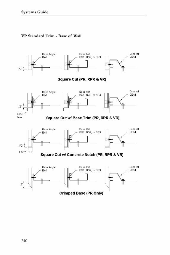
Systems Guide
240
VP Standard Trim - Base of Wall
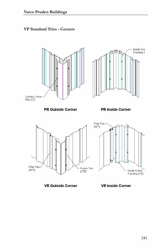
Varco Pruden Buildings
241
VP Standard Trim - Corners
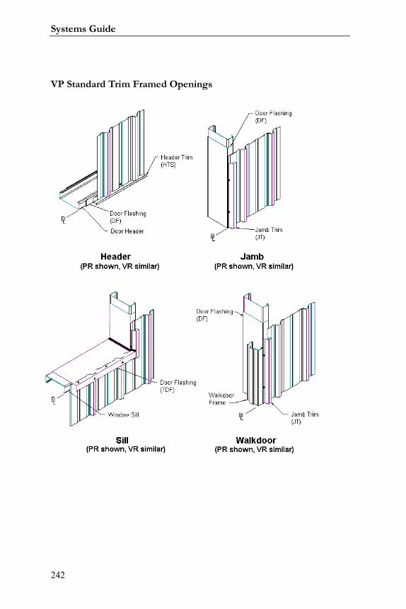
Systems Guide
242
VP Standard Trim Framed Openings
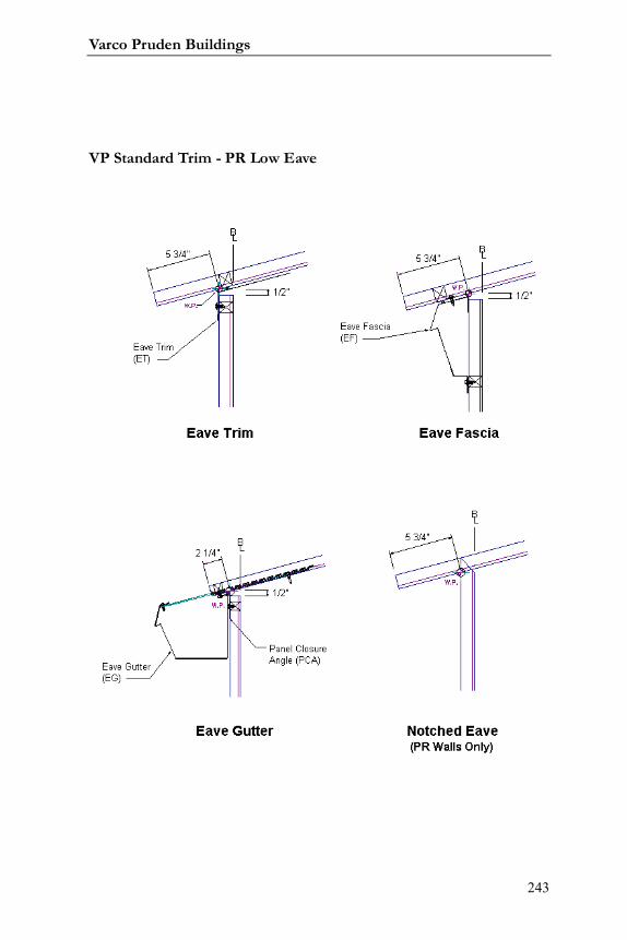
Varco Pruden Buildings
243
VP Standard Trim - PR Low Eave
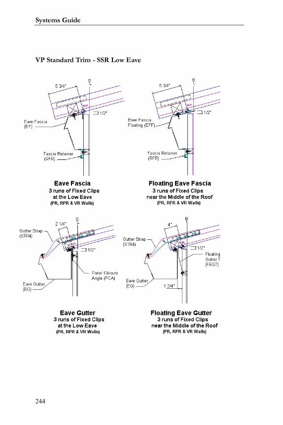
Systems Guide
244
VP Standard Trim - SSR Low Eave
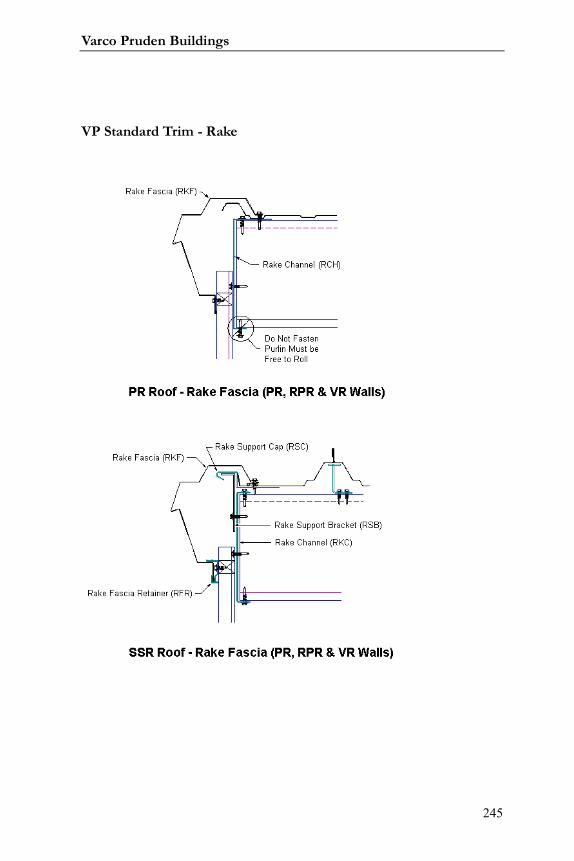
Varco Pruden Buildings
245
VP Standard Trim - Rake
VP Standard Trim - High Eave
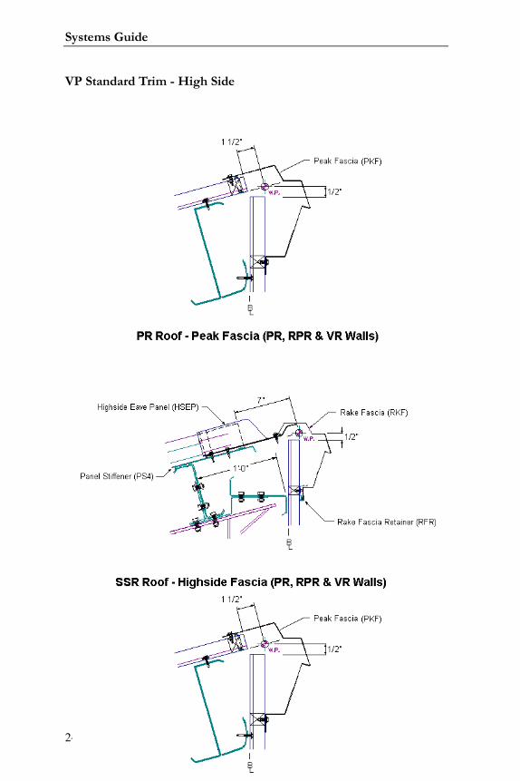
Systems Guide
246
VP Standard Trim - High Side
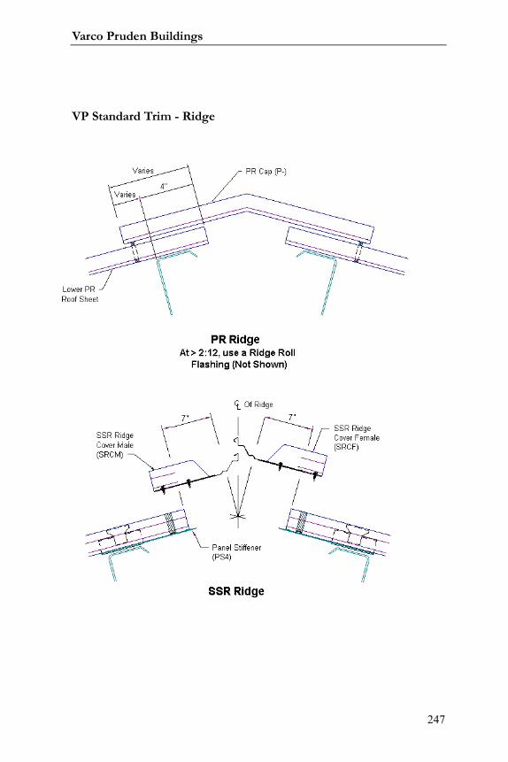
Varco Pruden Buildings
247
VP Standard Trim - Ridge
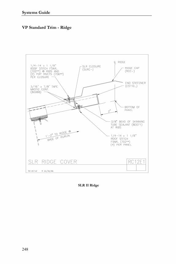
Systems Guide
248
VP Standard Trim - Ridge
SLR II Ridge
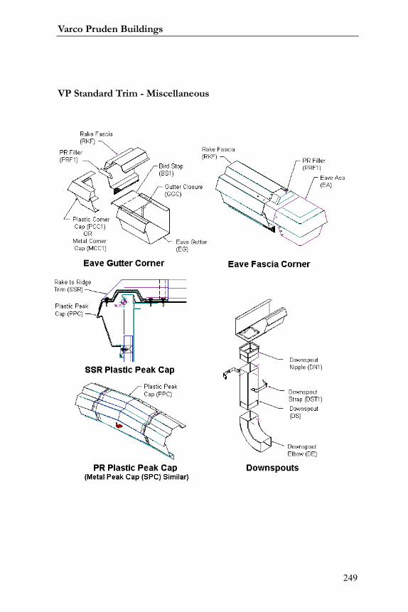
Varco Pruden Buildings
249
VP Standard Trim - Miscellaneous
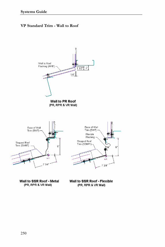
Systems Guide
250
VP Standard Trim - Wall to Roof
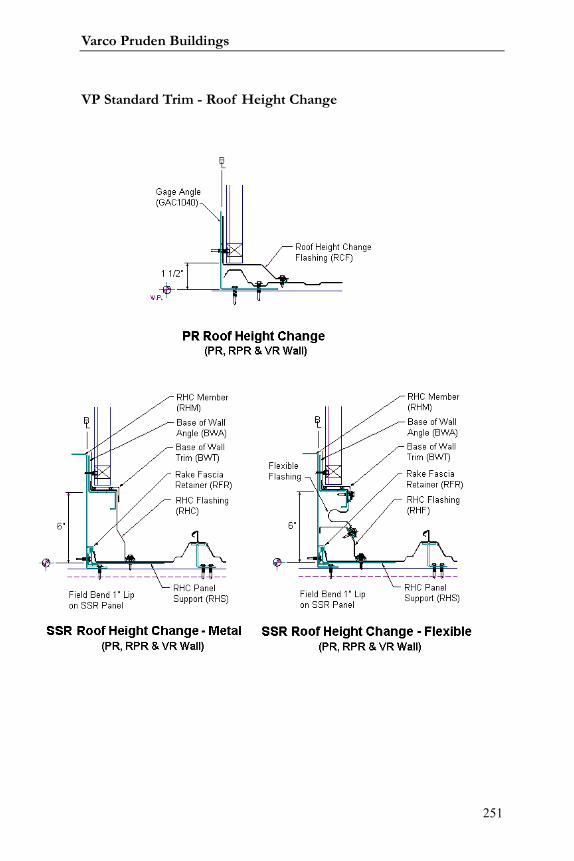
Varco Pruden Buildings
251
VP Standard Trim - Roof Height Change
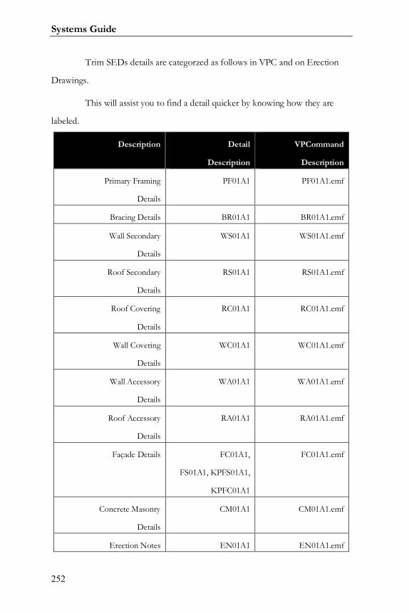
Systems Guide
252
Trim SEDs details are categorzed as follows in VPC and on Erection
Drawings.
This will assist you to find a detail quicker by knowing how they are
labeled.
Description Detail
Description
VPCommand
Description
Primary Framing
Details
PF01A1 PF01A1.emf
Bracing Details BR01A1 BR01A1.emf
Wall Secondary
Details
WS01A1 WS01A1.emf
Roof Secondary
Details
RS01A1 RS01A1.emf
Roof Covering
Details
RC01A1 RC01A1.emf
Wall Covering
Details
WC01A1 WC01A1.emf
Wall Accessory
Details
WA01A1 WA01A1.emf
Roof Accessory
Details
RA01A1 RA01A1.emf
Façade Details FC01A1,
FS01A1, KPFS01A1,
KPFC01A1
FC01A1.emf
Concrete Masonry
Details
CM01A1 CM01A1.emf
Erection Notes EN01A1 EN01A1.emf
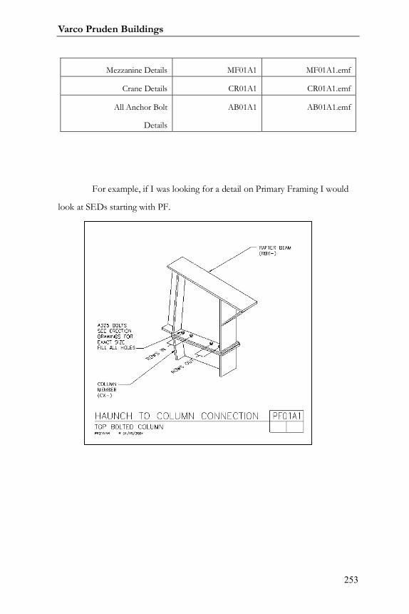
Varco Pruden Buildings
253
Mezzanine Details MF01A1 MF01A1.emf
Crane Details CR01A1 CR01A1.emf
All Anchor Bolt
Details
AB01A1 AB01A1.emf
For example, if I was looking for a detail on Primary Framing I would
look at SEDs starting with PF.

Systems Guide
254
Notes:

Varco Pruden Buildings
255
Notes:

Systems Guide
256
Varco Pruden Buildings
257
Liner Trim
Liner trim is to protect and hide the raw edges of the panels. This is an
appearance option and needs to be determined if it is desired by the owner.
Trim Questions for the Customer
Will interior trim be required where liner panels are required?
How detailed will the trim requirement be on the interior of the building?
Liner Trim Optimization Concepts
Interior liner trim is not required in many installations. Be sure
it is a requirement of the project before it is added.
If it is required, determine how elaborate the requirement will
be.
In VP Command the liner can include the soffit of any
overhangs, so be careful to include what is required in these areas.

Systems Guide
258
Notes:

Varco Pruden Buildings
259
Systems Guide
260
Accessory
A wide range of accessories are available. The purpose of this section is
to determine the quantity, location and types of accessories required.
Accessory Questions for the Customer
What types and quantities of door/windows should VP supply?
What type of door hardware is required?
Do you want wall-lights on the building?
Will there be louvers on the building?
What type roof curbs, ridge vents, tuf-lites or skylights will VP provide on
this project?
Are there any other “Special“ accessories VP can supply?
Accessory Optimization Concepts
VP doors and windows usually do not require framed
openings.
Door hardware is expensive; make sure you understand what
will be required.
While accessories will increase the cost of a building, they also
offer another area in which the service to the customer can be enhanced.
Do not overlook the ability to provide any accessory that is required. VP
Components6 can greatly assist with special accessory needs.
6 VP Components: phone – 877-983-7663; www.vpcomp.com
Varco Pruden Buildings
261
Accessory Description:
Accessories are components that can be added to a building in order to
develop a complete building package. The selection of accessories is dependent
on the type of roof and/or wall panel with which the accessory is to be provided.
Accessories are broken down into two categories:
Accessory Product Information:
Net Accessories:
"Net" accessories are items such as personnel doors, windows,
louvers, roof vents, wall lites, roof Tuf Lites and more. These accessories are
not subject to price adjustments.
Framed Openings: Are located in VP Command as specified
by the Builder. These openings vary in size. They include jambs, headers,
clips, bolts, fasteners, support girts, jamb extensions (where needed) jamb
and header cover flashing, panel trim at jambs and headers. Openings for
personnel doors, windows, and louvers are typically field located. Jambs and
header will match secondary unless opening will not design. Then it will
increase by 1 ½” until correct design depth is found.
Walk Door Kits: Standard walk doors provided by VP are
self-framing and self-flashing. Both single and double doors are available
with flush panels, half-glass panels or narrow-lite panels. There are multiple
hardware options available for the doors. The selection list found in VP
Systems Guide
262
Command is a Knock Down (KD) Door kit. Another option in VP
Command and the Supplemental Price Book are Pre-Assembled and
provided by Dominion Building Products.
Window Kits: Standard windows provided by VP are self-
framing and self-flashing. Various styles and sizes of windows with different
types of glass are available. Some of the windows available in VP Command
are: 2060 Fixed, 3040 Horizontal single hung, 3030 Horizontal Slide, 6030
and 6040 Horizontal Slide. Mullion Channels are available in order to locate
windows side-by-side. The windows in the Supplemental Price Book are
Pre-Assembled and provided by Dominion Building Products.
Louvers: The louvers offered by VP are self-framing and self-
flashing. Louvers available in VP Command are 3030 units with either fixed
or operable blades for Panel Rib and Vee Rib walls. Other sizes are available
by contacting your Service Center for Pricing.
Walk Door Canopies: These canopies are pre-assembled
units and include mounting angles, rods, fascia and drain. They are available
in 4'-6”× 4' and 7’-6” × 4' unit sizes within VP Command.
Apex 20 Vents: These are 20" diameter vents (At Ridge or
Sloped) complete with bird screen, damper and pull cord. They also include
a mounting base with fasteners and mastic. They should be added using VP
Command.
Varco Pruden Buildings
263
Ridge Ventilators: Ridge ventilators are 10' long units which
can be used as a single unit or as a continuous unit. Options are for either 9"
or 12" throat sizes. They include bird screen, damper and operating chain,
closures, fasteners and mastic.
Wall Lites: Wall Lites are nominally 3' × 5' white fiberglass
reinforced plastic panels configured to match Panel Rib or Vee Rib wall
panels. They are available with or without a UL-25 flame spread rating.
Roof Tuf Lites: Roof Tuf Lites are white woven fiberglass
plastic panels which are configured to match Panel Rib and SSR roof panels.
The Tuf Lite for Panel Rib is nominally 3' × 10'; the Tuf Lite for SSR is
nominally 2' × 10'. Tuf Lites are available with or without condensation
pans, UL-90 uplift rating and UL-25 flamespread rating. Fasteners, mastic,
and insulation trim are included with each Tuf Lite.
Tuff-Dome Skylite: Domed skylight with a “built-in-curb”
designed to work with VP’s roof panels. The superior weather resistance of
the polycarbonate material allows for better light trasmiision while resisting
yellowing, cracking, or fading. Tuf-dome is available in either insulated or
non-insulated models. They come complete with support framing and
installation kit that includes fasteners and mastic.
Dektites: These are EPDM flashing units which can be
utilized when pipes penetrate wither roof or wall panels. Sizes are available

Systems Guide
264
for varying pipe diameters; in addition, some sizes are available for high
temperature and retro-fit applications.
Roof Curbs: These special ordered curbs are specifically
made to fit every VP roof panel profile and can be priced using the
Supplemental Price Book. Other sizes are available by contacting your
Service Center for Pricing.
Varco Pruden Buildings
265
Notes:

Systems Guide
266
Varco Pruden Buildings
267
Pricing
The purpose of this section is to determine any optional warranty costs
that may be required that influence the price of the project.
Warranty
Warranty Questions for the Customer
Are Warranties other than the standard material warranties required?
o Weather tight warranty
o Optima Warranty
What Warranties are required on the panel finish
o KXL 20 year finish
Warranty Optimization Concepts
The cost of warranties should never be included in a project unless it is
a requirement to satisfy the owner. Make sure you understand VP Buildings’
offering in this area.
Also, make sure you understand your involvement in the warranty when
it is offered.
See the Warranties section within the Supplemental Price Book section
of Order Entry for the latest offerings.

Systems Guide
268
Notes:

Varco Pruden Buildings
269

Systems Guide
270
Deck Frame
Description:
Deck Frame is the utilization of VP Buildings’ economical three plate
materials, open web rafter materials, conventional structural shapes, bar joist, and
conventional “B” deck materials to design, manufacture, and deliver the most
economical building structure. Deck Frame projects can be combined with any
type lightweight non-metal roofing system commonly used in the conventional
construction market today.
By combining the ease of Metal Buildings with conventional roof
systems, you generate many more choices of building design. You can have
Metal or Non-Metal Roofing Systems, Metal Wall or Hard Wall Systems, Solid
Rafter system or Open Web Rafter Systems. These designs meet current trends,
as well as provide some aesthetic appearances, such as Level Parapet or Top of
Wall, Interior Drainage, better Water Management, and Framing for new Single
Ply Roofing Systems.
Features of Deck Frame projects:
Deck Frame merges VP Buildings’ designs and products with the design
and products of the Conventional Construction market.
Deck Frame - Framing options:
Open Web Rafter Members
Three Plate Solid Web Rafter Members (both straight and
tapered)
Varco Pruden Buildings
271
Three Plate Straight “H” columns, Tapered Columns, or Tube
Columns
Deck Frame Secondary options:
Conventional Bar Joist
Truss Purlin System
Hot-Rolled Shapes
Cold-Rolled Purlins
Deck Frame Bracing:
No Roof Rod Bracing
Metal Deck for Diaphragm Bracing
Deck Frame: Multiple Exterior Wall applications:
Load Bearing Tilt Wall
Load Bearing Pre-cast Wall
Load Bearing Masonry Wall
Exterior Columns for Non-Load Bearing Wall systems
Cold Formed Secondary Steel Girts for Metal Wall Application
Deck Frame: Roof applications:
B-Deck
All available gauges
Painted or Galvanized
Pinned, Screwed, Welded, or Mechanically fastened
Acoustical Deck Products
Systems Guide
272
Architectural Deck Products
Design for Flat of Tapered Insulation Systems
Lightweight Non-metal Roofing Systems
Deck Frame Roof products:
The VP Deck Frame Systems works great with any lightweight
non-metal commercial roofing system…
EPDM (Rubber Roofing)
TPO (Thermoplastic Polyolefin)
Built-up 2 and 4 ply systems
Ballasted
Batten-in-seam
Mechanically Fastened
Fully-Adhered.
Advantages of the Deck-frame product will produce a “The Winning
Combination” of the strength and economy of VP Buildings’ engineered
eonstruction eystems, the aesthetics and function of conventional construction
methods, with the best advantage being that there is one-source responsibility for
design, fabrication, and delivery
Deck Frame Estimating:
All Deck-Frame construction projects quotes, and service is performed
out of your location Service Center. You will need to contact your Estimating
Manager with Project Information, and she will quote the project.
Varco Pruden Buildings
273
Each project is evaluated, and a preliminary design must be looked at.
So Deck-Frame projects take longer than a normal project to quote. This is
generally up to two weeks from the time the information is received.

Systems Guide
274
Notes:
Varco Pruden Buildings
275
Systems Guide
276
Hybrid
Hybrid Description
Most pre-engineered buildings are single story, manufacturing, or
warehouse. Once a pre-engineered structure moves into large cranes, multi-level
mezzanines, and large clear spans (250’ or greater), it is hard to design because of
our manufacturing abilities. Hybrid Construction is an economical alternative to
“Conventional” Steel Buildings combining conventional hot-rolled shapes and
plate girders with typical pre-engineered structural components, secondary steel,
covering, and trim to design and construct the most efficient building structure
and enclosure possible.
Hybrid Estimating:
All hybrid construction projects, quotes, and services are performed in
of Memphis. You will need to contact your BDM or PDM with Project
Information, and they will contact the Estimating Group in Memphis. Each
project is evaluated, and a preliminary design must be looked at; hybrid projects
take longer than a normal project to quote. This is generally up to two weeks
from the time the information is received in Memphis.
Varco Pruden Buildings
277
Cost Savings
Cost savings up to 30% and greater on some projects when compared
to “conventional” steel design. Each project is very different, so careful
consideration must be given on each job. Following are some situations where
savings were great.
Saved over $6 million on an 800,000 s.f. Steel Processing
Facility.
Saved over $1 million on a 180,000 s.f. Mfg. Facility
Saved over $120,000 on an 80,000 s.f. Aircraft Hangar
Saved over $300,000 on a 185,000 s.f. Aircraft Hangar
Typical Buildings that can considered for Hybrid construction
All Buildings with Class “E” or “F” Cranes
Buildings with class “A”, “B”, or “C” Cranes that are 40 ton or
greater capacity
Crane buildings where the Crane rail heights are greater than
60 ft.
Arenas with clear span of greater than 250 ft. or where, due to
loading requirements, frames will not design in VP Command
Systems Guide
278
Aircraft Hangars with over 200 ft. spans and strict deflection
limitations
Aircraft Hangars where large door openings prevent the
normal use of sidewall columns
Aircraft or long-span buildings where the side wall columns are
taller than 60 ft.
Varco Pruden Buildings
279
Notes:

Systems Guide
280
Varco Pruden Buildings
281
Pricing Information
The Pricing / Additional Pricing information section of VPC will allow
you to input addition items that affect price such as your Competitive Allowance,
Warranty Information, SSR Seamer Rental, Freight, etc. You should also
calculate the building’s complexity (see following section and the Help screens
within VPCommand).
Systems Guide
282
Metal Buildings Manfacturer’s Association (MBMA) Complexity
MBMA Complexity - Simple
A rectangular building w/ solid web frames, purlins on the roof (any
depth), SSR or PR roof panel, solid sheeted walls (PR or VR), double or single
slope roof, standard rod bracing, user imposed point loads allowed, and any
standard accessories.
Standard Building Accessories:
Walk doors, windows, louvers, skylights, vents, liner panels, eave gutter,
etc.
MBMA Complexity - Medium
A building with any Category "B" or "C" items, but no more than (8)
complexity points.
Category "B" Items (Each one counts as 2 complexity points)
Open web frames, facades (vertical & mansard), skewed end walls,
South FL code, SLR roof, canopies over 10'-0", concealed fastener wall (Span
Loc, etc.), cranes up to 20 ton (class "C") perpendicular to frames, roof
extensions over 8'-0", masonry wind beams, sliding door (max 20' x 20'), furnish
mezzanine system, monorails not perpendicular to the frames, roof height
change, parapets, partitions, mini-warehouse.
Varco Pruden Buildings
283
Category "C" Items (Each one counts as 4 complexity points)
Special facades, skewed sidewalls, single hip, single valley, single jack beam,
hanger doors, bi-fold doors, dormers, cranes under 20 ton (class "C") not
perpendicular to frames, cranes over 20 ton (class "C") perpendicular to frames.
MBMA Complexity - Complex
A building with any Category "D" items, or more than (8) complexity
points.
Category "D" Items (Each one counts as 8 complexity points)
Both skewed sidewalls & end walls, cranes over 20 ton not running
perpendicular to the frames, any class "D" crane multiple hips or valleys, multiple
jack beams, octagon shapes, multiple level mezzanines.
MBMA Complexity - Factor
Total number of Complexity Points.
Category "B" Items (Each one counts as 2 complexity points)
Open web frames, facades (vertical & mansard), skewed end walls,
South FL code, SLR roof, canopies over 10'-0", concealed fastener wall (Span
Loc, etc.), cranes up to 20 ton (class "C") perpendicular to frames, roof
extensions over 8'-0", masonry wind beams, sliding door (max 20' x 20'), furnish
mezzanine system, monorails not perpendicular to the frames, roof height
change, parapets, partitions, mini-warehouse.
Category "C" Items (Each one counts as 4 complexity points)
Systems Guide
284
Special facades, skewed sidewalls, single hip, single valley, single jack
beam, hanger doors, bi-fold doors, dormers, cranes under 20 ton (class "C") not
perpendicular to frames, cranes over 20 ton (class "C") perpendicular to frames.
Category "D" Items (Each one counts as 8 complexity points)
Both skewed sidewalls & end walls, cranes over 20 ton not running
perpendicular to the frames, any class "D" crane multiple hips or valleys, multiple
jack beams, octagon shapes, multiple level mezzanines.

Varco Pruden Buildings
285
Notes:

Systems Guide
286
Varco Pruden Buildings
287
Other Topics
These topics may be outside the normal input of VP Command, and
may require consultation with VP for pricing. The purpose of this section is to
determine if these elements are required in the project. Refer to VP’s order
clarification documents to assist with these additional building features.
Questions for the Customer
Mezzanines
Is there a mezzanine or elevated floor in the project?
If there is a Mezzanine is it supported by our building structure or is it an
independent structure?
What will the mezzanine be used for (this will control the design live
load)?
Will stairwell openings be required? If so, what size and location?
What will the Mezzanine floor material be?
o Poured concrete (thickness)
o Lightweight concrete (thickness)
o Gypsum
o Grating
o Steel Plate
o Wood
Can the mezzanine be used to help brace the building?
What are the required clearances for the mezzanine
Finished Floor elevation
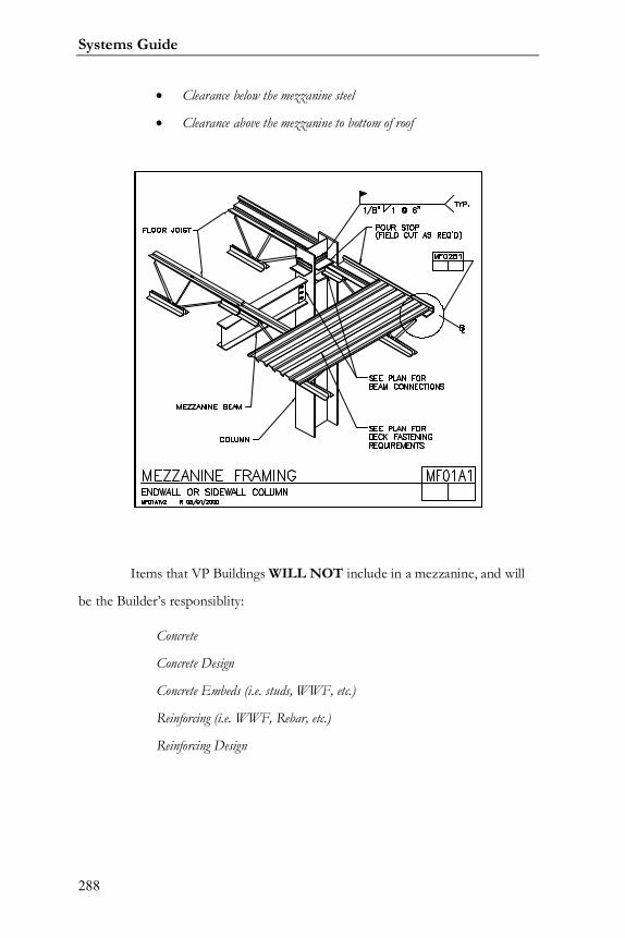
Systems Guide
288
Clearance below the mezzanine steel
Clearance above the mezzanine to bottom of roof
Items that VP Buildings WILL NOT include in a mezzanine, and will
be the Builder’s responsiblity:
Concrete
Concrete Design
Concrete Embeds (i.e. studs, WWF, etc.)
Reinforcing (i.e. WWF, Rebar, etc.)
Reinforcing Design
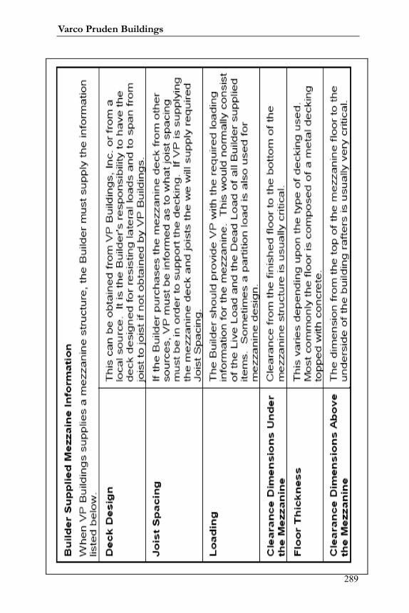
Varco Pruden Buildings
289

Systems Guide
290
Notes:

Varco Pruden Buildings
291
Facades and Parapets
See previous sections on facades and parapets for more
information.
What is the reason for having a Façade/Parapet?
o Is it an architectural element?
o Designed to enhance the look of the building?
o Is it to cover Roof Top Units (RTU) and/or roof slope?
What type of material is used for construction of the Façade/Parapet?
o Define the geometry of the Façade/Parapet, i.e., open or closed,
mansard vs. straight.
o Height?
o Projection?
o Etc.
Systems Guide
292
Partitions
What is the function of the Partition wall?
o Fire protection.
o Noise reduction.
o Restrict or control air flow and/or smoke
o Insulate portion of the building.
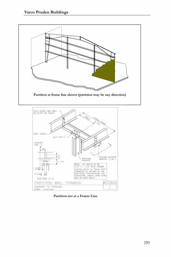
Varco Pruden Buildings
293
Partition at frame line shown (partition may be any direction)
Partition not at a Frame Line

Systems Guide
294
Carrier / Jack Beams
These structural members act as both Primary and Secondary to
approach wide bay applications. Jack Beams (solid web members) or Jack
Trusses (open web members) permit extra wide bay spacing while using an
economical purlin system. These interior members are typically utilized with
either a Continuous Truss or Continuous Beam system to eliminate the need for
a column where an open space is required for machinery, storage, or other
purposes.
Jack Beam/Frame at Sidewall Shown (Jack Beams may be used to “jack-out” interior framing locations as well)
Varco Pruden Buildings
295
Other Topics Optimization Concepts
Mezzanines can be a major element of the building project.
Find out as much as you can from the owner about what he needs, then
determine the best approach to providing the mezzanine. If it is to be by
VP, the framing of the materials will be critical to the economy of the
building.
Facades and parapets may be required to change the
appearance of the building or to make a statement in the marketplace. They
may be to support signs or to provide a required appearance of the building.
Whatever the reason, they can be an expensive element of the building. In
addition, there are some methods of constructing Facades that are more
expensive than others. Before quoting the more expensive alternatives,
make sure they are required.
Partitions are usually required to separate functional areas in a
building. The proper application of materials is necessary to provide the best
solution. VP can provide partitions with metal panels. If other materials are
required, it may be more economical to use metal studs to achieve the
partition.
Partitions can run any direction. VPCommand allows the
flexibility to have diagonal partitions if desired.
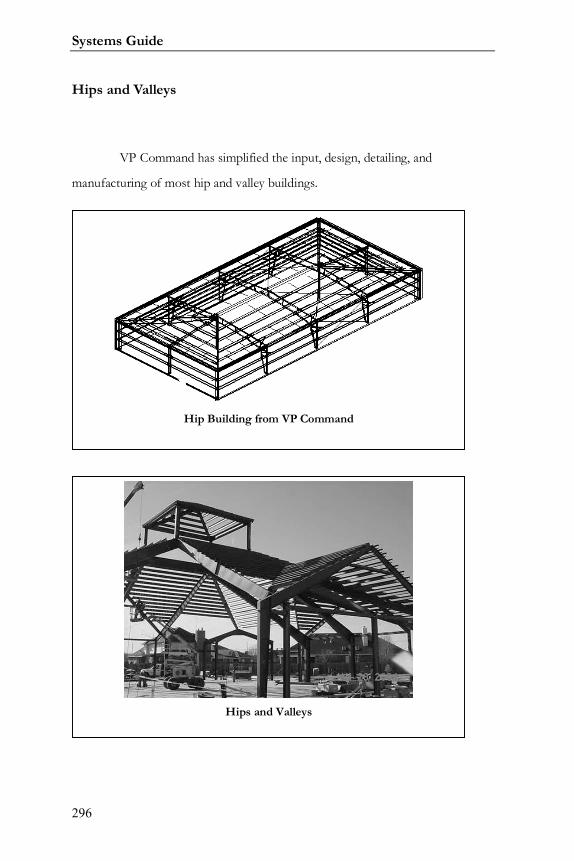
Systems Guide
296
Hips and Valleys
VP Command has simplified the input, design, detailing, and
manufacturing of most hip and valley buildings.
Hip Building from VP Command
Hips and Valleys
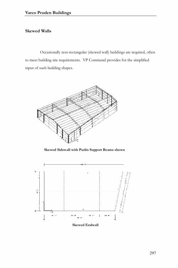
Varco Pruden Buildings
297
Skewed Walls
Occasionally non-rectangular (skewed wall) buildings are required, often
to meet building site requirements. VP Command provides for the simplified
input of such building shapes.
Skewed Sidewall with Purlin Support Beams shown
Skewed Endwall
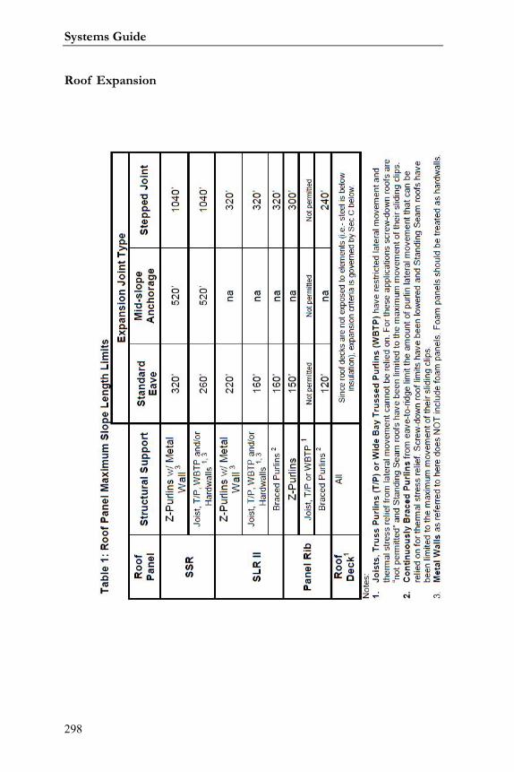
Systems Guide
298
Roof Expansion
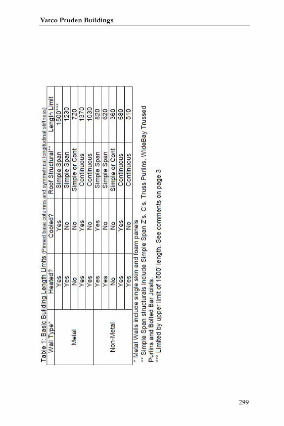
Varco Pruden Buildings
299

Systems Guide
300

Varco Pruden Buildings
301
Notes:

Systems Guide
302
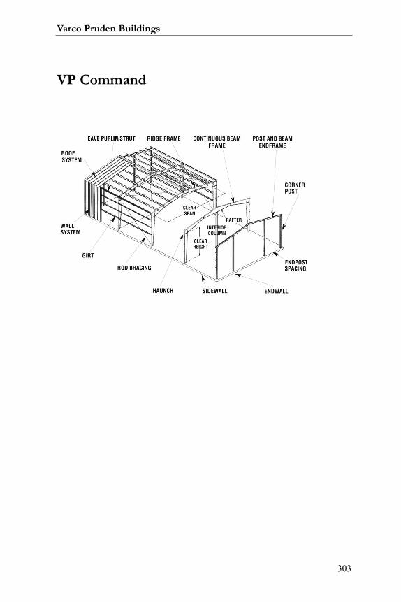
Varco Pruden Buildings
303
VP Command
Systems Guide
304
Additional VP Command (VPC) Items7
Building Editor: This function is where you will spend the majority of
your VPCommand time. The Building Editor is where you define your project,
applying geometry, loading, panel types, framing and secondary types, etc. to
create the project, as you desire.
Drawings: This function allows you to generate preliminary drawings
such as Anchor Bolt layouts, Frame Cross Sections, Standard Erection Details,
etc. The VPC drawing option also allows you to generate any VPC drawing to a
“.dxf” or “.dwg” file format for use in CAD packages.
Read-me File: This option will display information relative to
VPCommand and what has been added for the current version you have loaded.
7 By Stephen Hudák
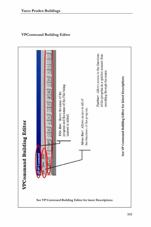
Varco Pruden Buildings
305
VPCommand Building Editor
See VP Command Building Editor for latest Descriptions
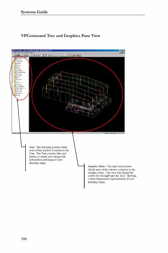
Systems Guide
306
VPCommand Tree and Graphics Pane View
Varco Pruden Buildings
307
VPCommand Tree Description
The “Tree” is where the majority of the action takes place in
VPCommand. The tree is the left-hand portion of the screen within the Building
Editor function. The right-hand portion of this screen is called the “Graphics
Pane” which we will discuss later in more detail. A “Tree” in the VP Command
sense is similar to a real, living tree that has larger branches, and smaller branches
extending from the larger branches.
The Tree has a “hierarchical” set of folders for each available topic.
Webster’s dictionary defines a hierarchy as “a system of church government by
priests or other clergy in graded ranks”. What does this definition have to do
with VPCommand you may ask? Absolutely nothing! Another definition of
hierarchy is “a group of persons or things arranged in order of rank, grade, class, etc”.
Think of a hierarchy as an upside-down pyramid, with the large base
containing a majority of information for a topic (for ex., frames, covering, etc.)
going down to the tip of the pyramid containing more detailed information for
that topic (for ex., the flange thickness of a column, the sheeting direction of
panels on a particular wall, etc.). Items listed in the Tree follow this “upside-
down flow.” Information contained at one level (consider Covering) applies to
ALL folders and/or files within that topic unless changed at a lower level. If
changed, information from that point downward within the topic applies.
Let’s think about this hierarchy, files, and folders stuff another way.
Consider socks. Yes, I said socks, those things you wear on your feet. Think of
Systems Guide
308
your sock drawer as a Folder. Within that drawer-folder are contained your
socks. The drawer is the Folder, the socks are the files. Within that main drawer-
folder, you may wish to create compartments in the drawer to separate your socks
according to color. In this case, the main drawer is a folder called “socks”
containing other compartment-folders called “Black Socks” and “White Socks”.
The socks in each compartment are the files. If you get really obsessive-
compulsive, you can further break down your socks in each compartment
according to their fabric, the day of the week in which to wear them, etc.
Now, with this socks stuff in mind, let’s look at it in VPCommand
terms. Consider Covering. Covering is the main sock drawer-folder. Within this
folder are compartments called “Default Information” and “Data” (White and
Black Socks). Within the Default Information and Data folders are additional
folders and files (Wool Socks, Tuesday Socks, etc.). Information contained in the
Default Information folder is applied to all folders and/or files below, unless
changes are made. For example, the Default Information may contain Panel Rib
Roof (White Socks). If I move down to my Shape folder and change my roof
panel to SSR (Green Socks), the green socks will take precedence for my shape.
It will not, however, have any effect at the upper lever folders. If I add green
socks to my white sock drawer, it will always contain green socks until I remove
them! Thus, my shape will always have SSR until I change it at the shape level. If
you make a change in the tree, you have taken ownership of that file and your
change will be maintained until YOU modify or delete it!
Continuing our discussion of the Tree and how to work within it, see
the following pages to look at the Toolbar and how it changes to allow functions
applicable to the Tree as well as a discussion of the various catrgories within the
tree.
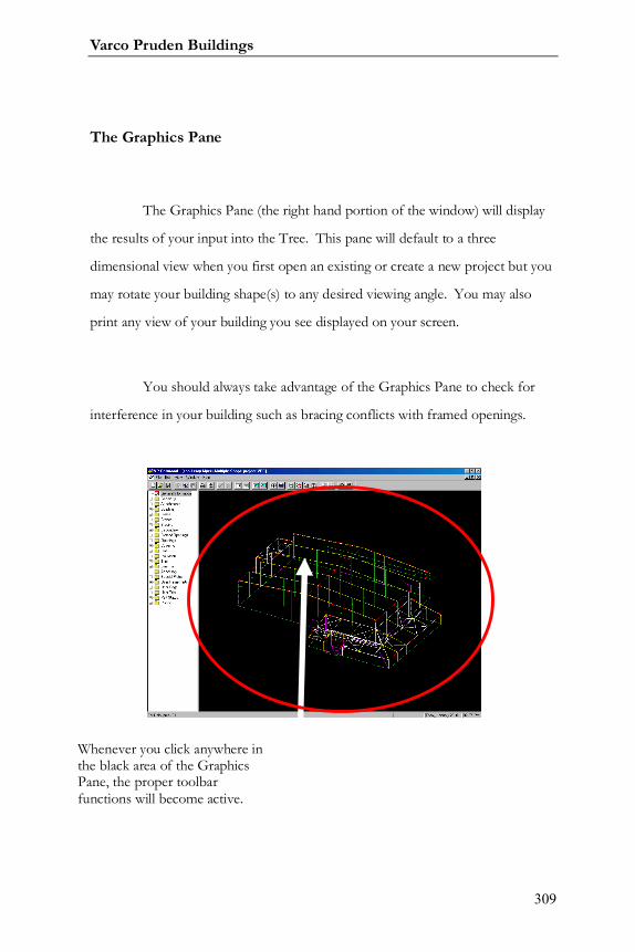
Varco Pruden Buildings
309
The Graphics Pane
The Graphics Pane (the right hand portion of the window) will display
the results of your input into the Tree. This pane will default to a three
dimensional view when you first open an existing or create a new project but you
may rotate your building shape(s) to any desired viewing angle. You may also
print any view of your building you see displayed on your screen.
You should always take advantage of the Graphics Pane to check for
interference in your building such as bracing conflicts with framed openings.
Whenever you click anywhere inthe black area of the GraphicsPane, the proper toolbarfunctions will become active.
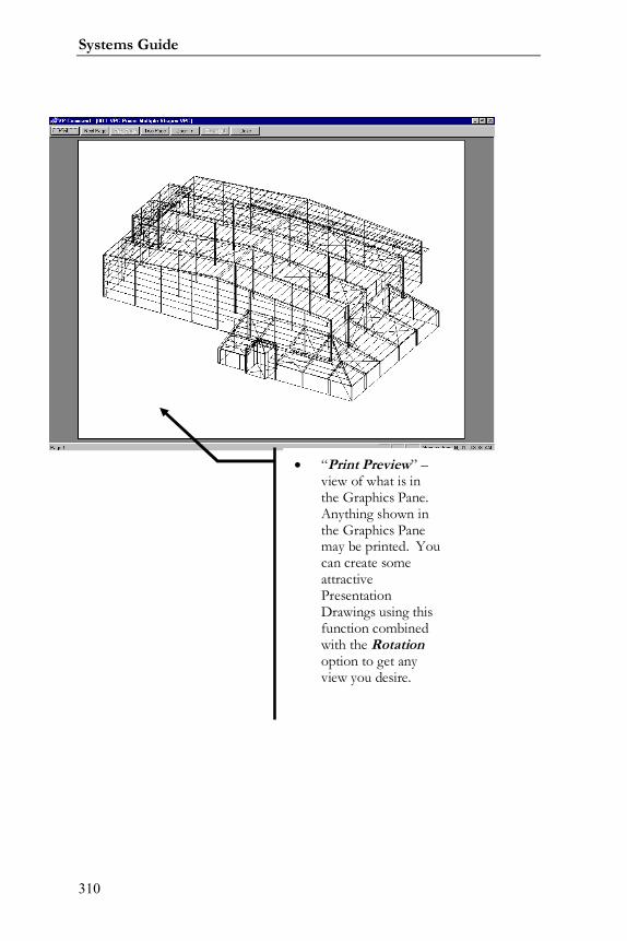
Systems Guide
310
“Print Preview” –view of what is inthe Graphics Pane.Anything shown inthe Graphics Panemay be printed. Youcan create someattractivePresentationDrawings using thisfunction combinedwith the Rotationoption to get anyview you desire.
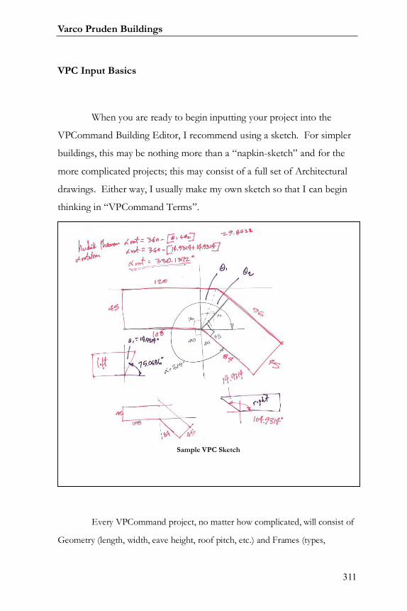
Varco Pruden Buildings
311
VPC Input Basics
When you are ready to begin inputting your project into the
VPCommand Building Editor, I recommend using a sketch. For simpler
buildings, this may be nothing more than a “napkin-sketch” and for the
more complicated projects; this may consist of a full set of Architectural
drawings. Either way, I usually make my own sketch so that I can begin
thinking in “VPCommand Terms”.
Every VPCommand project, no matter how complicated, will consist of
Geometry (length, width, eave height, roof pitch, etc.) and Frames (types,
Sample VPC Sketch
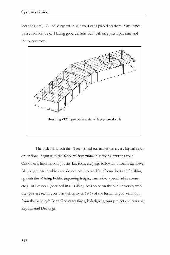
Systems Guide
312
locations, etc.). All buildings will also have Loads placed on them, panel types,
trim conditions, etc. Having good defaults built will save you input time and
insure accuracy.
The order in which the “Tree” is laid out makes for a very logical input
order flow. Begin with the General Information section (inputting your
Customer’s Information, Jobsite Location, etc.) and following through each level
(skipping those in which you do not need to modify information) and finishing
up with the Pricing Folder (inputting freight, warranties, special adjustments,
etc.). In Lesson 1 (obtained in a Training Session or on the VP University web
site) you use techniques that will apply to 99 % of the buildings you will input,
from the building’s Basic Geometry through designing your project and running
Reports and Drawings.
Resulting VPC input made easier with previous sketch
Varco Pruden Buildings
313
VPC Defaults
What are “Defaults”?: Think of Default projects as a baseline or
beginning point. A Default building contains information that will be applied to
the project you create using this default. The intent of Defaults is to save you
input time and to insure accuracy for your projects. The less information you
have to input, the less chance for error or forgetting items. We will look at each
item in the “Tree” of the Building Editor and look at some considerations you
should make pertaining to YOUR default projects.
What can be Defaulted?: Basically, any information that is not
“dimensional” can be defaulted. Items such as Loads and Codes, Panel
Information (types, finishes, colors, etc.), trim preferences, etc. can be defaulted.
Some Dimensional items such as a 10 x 12 framed opening centered in a bay of a
wall cannot be defaulted. The 10 x 12 framed opening can be defaulted, but its
location cannot. Building Geometry, as well, cannot be defaulted (length, width,
eave height, etc.)
How many Defaults can I have?: You can have as many defaults as
you wish. Some users have defaults for all possible roof and wall panel
conditions (SSR-PR, PR-PR, SSR-VR, etc.), some have Defaults for various
loading conditions in the counties and/or states they work. But the key is to
have good defaults that work for you! It is important to name your defaults
something you can relate to. I have adopted the method of abbreviating my
defaults as follows: 2006 IBC Warren County, Virginia SSR PR EG CR 4r
3w. To me this means, Standing Seam Roof, Panel Rib Walls, Eave Gutter and
Downspouts, Crimped Base, 4” and 3” insulation in the roof and walls respectively with
Systems Guide
314
2006 IBC loading in Warren County, Virginia. Use any name designation that makes
sense to you.
Updating Defaults: Update your default projects as often as needed.
If you find yourself making repetitive changes to a lot of your projects, such as
adding 3” VRV insulation, then simply open your default and apply this change.
However, if you are using old defaults, you must update these or delete
and create new Default projects in order to take advantage of the VP
Buildings standard product default conditions. With each new version of
VPC, read the included documentation as well as the “Read-Me” file to see what
is new.

Varco Pruden Buildings
315
Notes:
Systems Guide
316
Description of VPCommand (VPC) Colors
Frames: Red Frames indicates that the frame designed and detailed
completely.
Frames: Yellow indicates that the frame has not been designed or
Interactive Design is required. This member has not priced.
Secondary: Cyan (Light Blue) Secondary indicates the secondary has
designed and detailed.
Secondary: White Secondary indicates that the secondary has not been
designed or that design has failed for that member. This member has not priced.
Bracing: Yellow Bracing indicates that the bracing member has been
designed and detailed.
Bracing: White Bracing indicates that the bracing member has not
been designed or that design has failed for that member. This member has not
priced.
Trim: Salmon (Pink) Trim indicates that a trim segment has generated.
You must verify on the Reports if there are any unpriced trim items.
Trim: Red-Dashed Lines indicate that the trim segment has not been
generated.
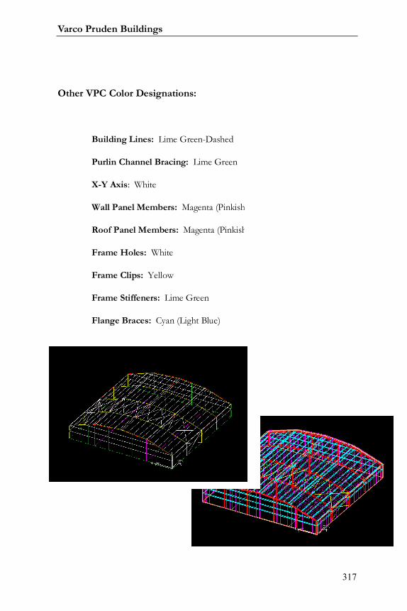
Varco Pruden Buildings
317
Other VPC Color Designations:
Building Lines: Lime Green-Dashed
Purlin Channel Bracing: Lime Green
X-Y Axis: White
Wall Panel Members: Magenta (Pinkish)
Roof Panel Members: Magenta (Pinkish)
Frame Holes: White
Frame Clips: Yellow
Frame Stiffeners: Lime Green
Flange Braces: Cyan (Light Blue)
Reviewing Drawings andDetails
Prior to VPC
Systems Guide
318
In your never-ending quest to make certain that you receive the parts
and pieces you believe you are inputting into VPCommand, following are some
recommendations. This is the minimum items I complete on any VPC file I
input.
1. Thoroughly review Input Report.
2. Complete and Save VPC-Run (Run / Run All)
function
3. Visually Review the resulting “Colors” in the
Graphics Pane in the Building Editor. See VPC-Tip #2 on the VP
University website for more information on this.
4. Run and Review Pricing and Edit Check Reports.
Look for the asterisks (*), and address as necessary. Remember to
review the Engineering Content section.
5. When I feel I am getting what I need, I generate
some Drawings and the Standard Erection Details SEDs) to review
(you can view these on screen or print out if you desire). If my SEDs
show Panel Rib roof details, and I thought I input SSR, chances are that
my Input is not correct. A common mistake is to have SSR on the main
roof, and then I input a canopy and forgot to set this up in my Default
accordingly or forgot to change it during input.

Varco Pruden Buildings
319
How To Use the Engineering Content Screen
Follow these steps:
Open the pricing folder and double click the Engineering
Content to review the conditions.
Engineering Content Screen (See VPCommand for latest screen)
Pricing folder in VPC TreeSee VPC for latest screen
Systems Guide
320
Revised: Show the status of the condition. If the condition was added by the
system it will show No, in that the status of that item was set but has not been changed by
the user. If the user has modified a system generated or user input item the status will
show Yes.
System: Shows the quantity of system detected conditions.
User: Shows the quantity of user input conditions.
Generate: Shows the type of condition, either System or User. A system
condition should be detected by VP Command automatically. A user condition must be
entered by the user.
Category: Shows the category of input the condition is in. JPU stands for Job
Processing Units used internally by Varco Pruden.
Description: Shows a brief description of the condition.
All system generated quantities should be verified by the user before final pricing. Any
quantities that are incorrect may be overridden by typing the correct quantity in the user
quantity field. To type a quantity, simply click in the desired field and type the number.
When all user changes are complete you can click the Lock Current Values
check box so that the engineering content values will not change if the job is re-run. This
should only be used when the pricing is finalized.
Once all input is complete click OK and save the project.
Varco Pruden Buildings
321
Engineering Content Charges
Each point added in the engineering content list is worth a particular
dollar amount and is applied towards an engineering fee. An itemized break
down of conditions and points is shown at the end of the pricing report. There is
also a new category on the pricing summary to show the net engineering fee
added.
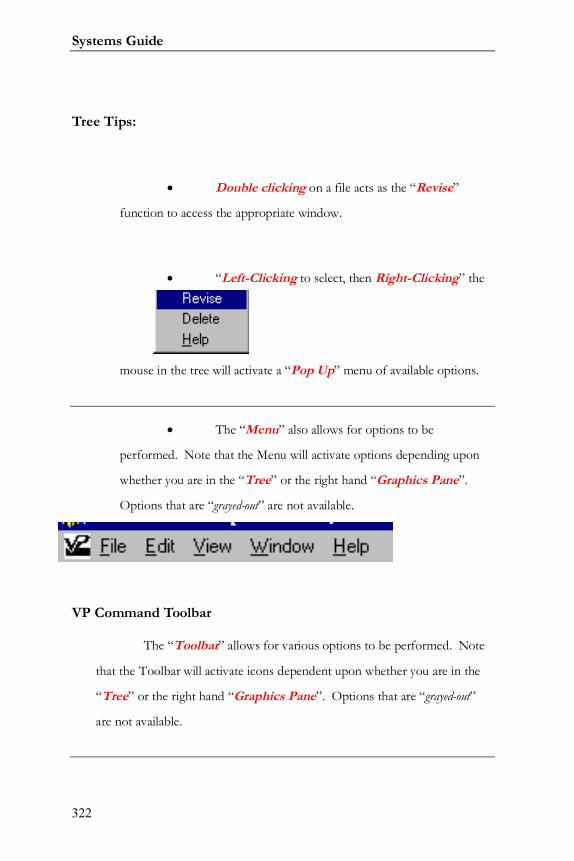
Systems Guide
322
Tree Tips:
Double clicking on a file acts as the “Revise”
function to access the appropriate window.
“Left-Clicking to select, then Right-Clicking” the
mouse in the tree will activate a “Pop Up” menu of available options.
The “Menu” also allows for options to be
performed. Note that the Menu will activate options depending upon
whether you are in the “Tree” or the right hand “Graphics Pane”.
Options that are “grayed-out” are not available.
VP Command Toolbar
The “Toolbar” allows for various options to be performed. Note
that the Toolbar will activate icons dependent upon whether you are in the
“Tree” or the right hand “Graphics Pane”. Options that are “grayed-out”
are not available.
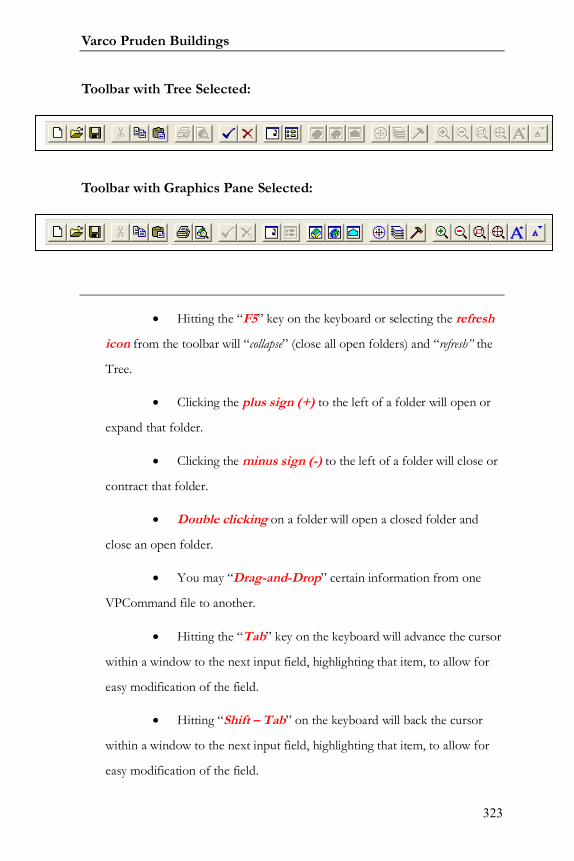
Varco Pruden Buildings
323
Toolbar with Tree Selected:
Toolbar with Graphics Pane Selected:
Hitting the “F5” key on the keyboard or selecting the refresh
icon from the toolbar will “collapse” (close all open folders) and “refresh” the
Tree.
Clicking the plus sign (+) to the left of a folder will open or
expand that folder.
Clicking the minus sign (-) to the left of a folder will close or
contract that folder.
Double clicking on a folder will open a closed folder and
close an open folder.
You may “Drag-and-Drop” certain information from one
VPCommand file to another.
Hitting the “Tab” key on the keyboard will advance the cursor
within a window to the next input field, highlighting that item, to allow for
easy modification of the field.
Hitting “Shift – Tab” on the keyboard will back the cursor
within a window to the next input field, highlighting that item, to allow for
easy modification of the field.

Systems Guide
324
Use the “Notes” tabs within VPCommand windows to better
clarify your intentions.
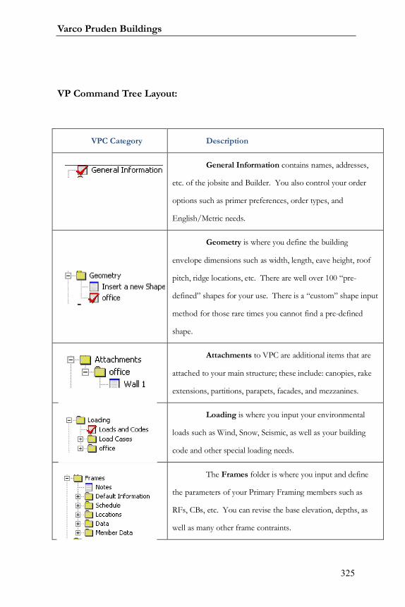
Varco Pruden Buildings
325
VP Command Tree Layout:
VPC Category Description
General Information contains names, addresses,
etc. of the jobsite and Builder. You also control your order
options such as primer preferences, order types, and
English/Metric needs.
Geometry is where you define the building
envelope dimensions such as width, length, eave height, roof
pitch, ridge locations, etc. There are well over 100 “pre-
defined” shapes for your use. There is a “custom” shape input
method for those rare times you cannot find a pre-defined
shape.
Attachments to VPC are additional items that are
attached to your main structure; these include: canopies, rake
extensions, partitions, parapets, facades, and mezzanines.
Loading is where you input your environmental
loads such as Wind, Snow, Seismic, as well as your building
code and other special loading needs.
The Frames folder is where you input and define
the parameters of your Primary Framing members such as
RFs, CBs, etc. You can revise the base elevation, depths, as
well as many other frame contraints.
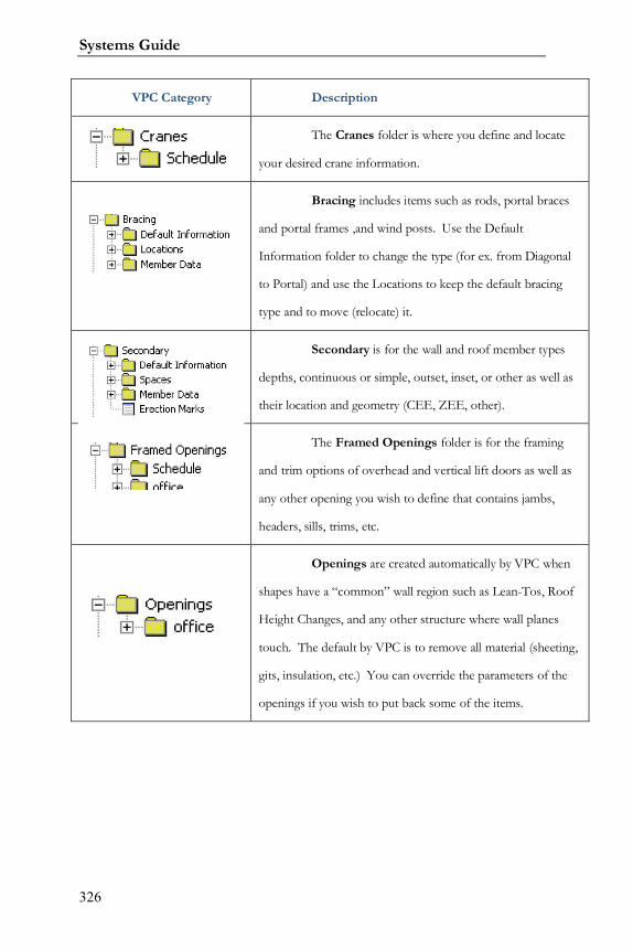
Systems Guide
326
VPC Category Description
The Cranes folder is where you define and locate
your desired crane information.
Bracing includes items such as rods, portal braces
and portal frames ,and wind posts. Use the Default
Information folder to change the type (for ex. from Diagonal
to Portal) and use the Locations to keep the default bracing
type and to move (relocate) it.
Secondary is for the wall and roof member types
depths, continuous or simple, outset, inset, or other as well as
their location and geometry (CEE, ZEE, other).
The Framed Openings folder is for the framing
and trim options of overhead and vertical lift doors as well as
any other opening you wish to define that contains jambs,
headers, sills, trims, etc.
Openings are created automatically by VPC when
shapes have a “common” wall region such as Lean-Tos, Roof
Height Changes, and any other structure where wall planes
touch. The default by VPC is to remove all material (sheeting,
gits, insulation, etc.) You can override the parameters of the
openings if you wish to put back some of the items.
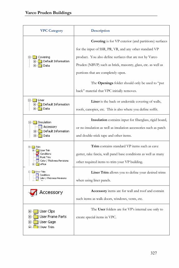
Varco Pruden Buildings
327
VPC Category Description
Covering is for VP exterior (and partitions) surfaces
for the input of SSR, PR, VR, and any other standard VP
product. You also define surfaces that are not by Varco
Pruden (NBVP) such as brick, masonry, glass, etc. as well as
portions that are completely open.
The Openings folder should only be used to “put
back” material that VPC initially removes.
Liner is the back or underside covering of walls,
roofs, canopies, etc. This is also where you define soffit.
Insulation contains input for fiberglass, rigid board,
or no insulation as well as insulation accessories such as patch
and double-stick tape and other items.
Trim contains standard VP items such as eave
gutter, rake fascia, wall panel base conditions as well as many
other required items to trim your VP building.
Liner Trim allows you to define your desired trims
when using liner panels.
Accessory items are for wall and roof and contain
such items as walk doors, windows, vents, etc.
The User folders are for VP’s internal use only to
create special items in VPC.
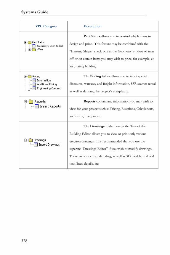
Systems Guide
328
VPC Category Description
Part Status allows you to control which items to
design and price. This feature may be combined with the
“Existing Shape” check box in the Geometry window to turn
off or on certain items you may wish to price, for example, at
an existing building.
The Pricing folder allows you to input special
discounts, warranty and freight information, SSR seamer rental
as well as defining the project’s complexity.
Reports contain any information you may wish to
view for your project such as Pricing, Reactions, Calculations,
and many, many more.
The Drawings folder here in the Tree of the
Building Editor allows you to view or print only various
erection drawings. It is recommended that you use the
separate “Drawings Editor” if you wish to modify drawings.
There you can create dxf, dwg, as well as 3D models, and add
text, lines, details, etc.
Varco Pruden Buildings
329
Notes:
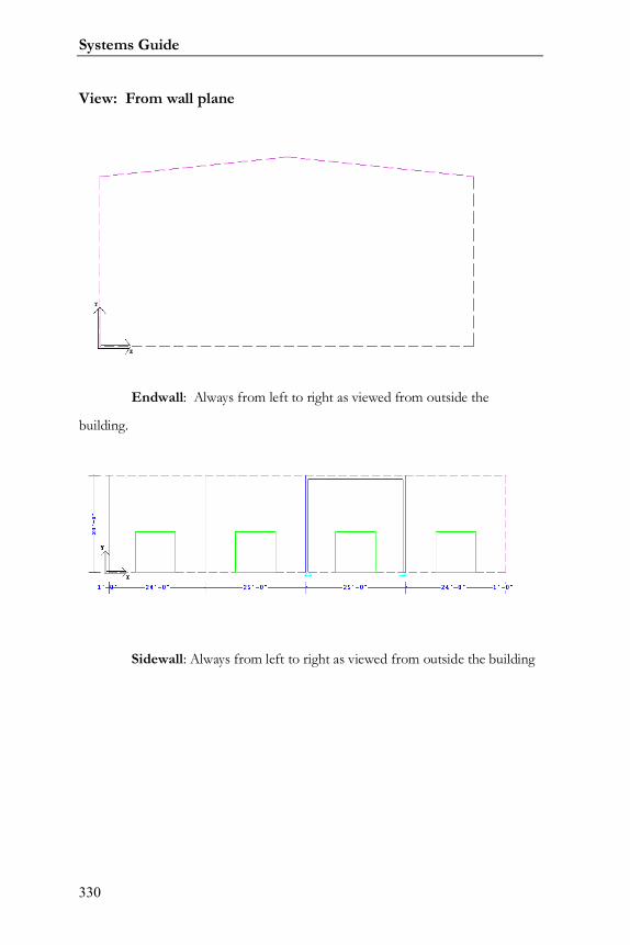
Systems Guide
330
View: From wall plane
Endwall: Always from left to right as viewed from outside the
building.
Sidewall: Always from left to right as viewed from outside the building
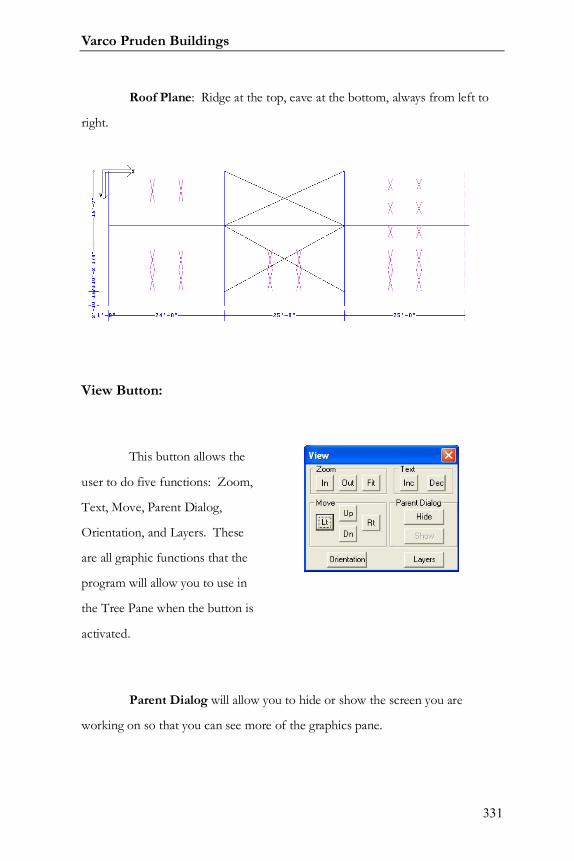
Varco Pruden Buildings
331
Roof Plane: Ridge at the top, eave at the bottom, always from left to
right.
View Button:
This button allows the
user to do five functions: Zoom,
Text, Move, Parent Dialog,
Orientation, and Layers. These
are all graphic functions that the
program will allow you to use in
the Tree Pane when the button is
activated.
Parent Dialog will allow you to hide or show the screen you are
working on so that you can see more of the graphics pane.
Eave
Ridge
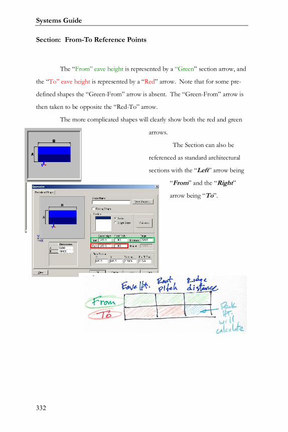
Systems Guide
332
Section: From-To Reference Points
The “From” eave height is represented by a “Green” section arrow, and
the “To” eave height is represented by a “Red” arrow. Note that for some pre-
defined shapes the “Green-From” arrow is absent. The “Green-From” arrow is
then taken to be opposite the “Red-To” arrow.
The more complicated shapes will clearly show both the red and green
arrows.
The Section can also be
referenced as standard architectural
sections with the “Left” arrow being
“From” and the “Right”
arrow being “To”.
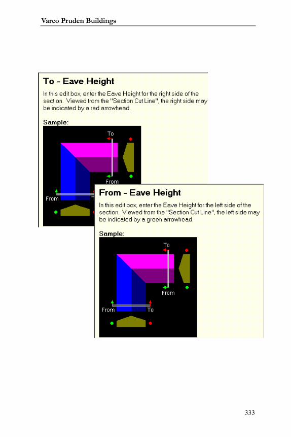
Varco Pruden Buildings
333
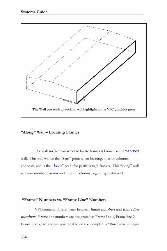
Systems Guide
334
“Along” Wall – Locating Frames
The wall surface you select to locate frames is known as the “ALONG”
wall. This wall will be the “Start” point when locating; interior columns,
endposts, and is the “LEFT” point for partial length frames. This “along” wall
will also number exterior and interior columns beginning at this wall.
“Frame” Numbers vs. “Frame Line” Numbers
VPCommand differentiates between frame numbers and frame line
numbers. Frame line numbers are designated as Frame line 1, Frame line 2,
Frame line 3, etc. and are generated when you complete a “Run” which designs
The Wall you wish to work on will highlight in the VPC graphics pane
Varco Pruden Buildings
335
and details your building, whereas Frame numbers are literally the number of that
frame going from left to right as you are facing the wall surface standing
outside your shape. Frame numbers have nothing to do with the “Along” wall!
They are counted as 1, 2, 3, etc., at each surface as you are facing that wall.
Using frame numbers is very convenient for complex shapes. You simply count
the frames from left to right as you face the selected wall rather than trying to
figure out if this is frame line U7, or frame line B, etc.
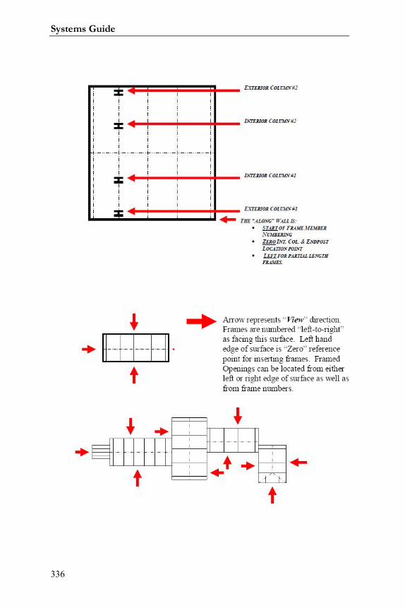
Systems Guide
336

Varco Pruden Buildings
337
Notes:
Systems Guide
338
VPCommand Parts Status
The VP Command Parts Status section can be used to control which
parts and pieces you wish to price. For example, you can use this to remove
material at existing building conditions. There may be times you wish to leave
some items to design, detail, and price for existing buildings such at a wall that is
higher than the new shape. You can leave the required secondary, trim, etc. to
“run” and use for the existing building.
In the geometry section of VPC there is a check box for “existing
shape.” You may use this to specify the entire shape as existing and thereby
“turning off” all items (pertaining to the existing shape) at the Parts Status level.
VPCommand Drawings
In the VPC Building Editor there is a folder for “Drawings.” In this
level you can view and print Drawings. When you create drawings they are “as
designed” at that time; if you revise anything within VPC any created drawings
are not updated, your must create new ones.
The “VPC Drawings Editor” offers more flexibility and options
concerning drawings. At the function you can create, plot, revise, etc. your
drawings. You can create “dxf” and “dwg” files as well as three-dimensional
models to use in your other drawing applications.
See the “Help” section within the drawing editor for additional
information.
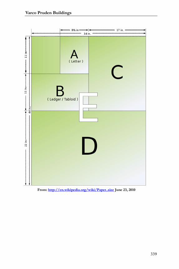
Varco Pruden Buildings
339
From: http://en.wikipedia.org/wiki/Paper_size June 23, 2010
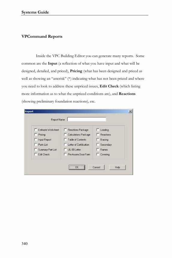
Systems Guide
340
VPCommand Reports
Inside the VPC Building Editor you can generate many reports. Some
common are the Input (a reflection of what you have input and what will be
designed, detailed, and priced), Pricing (what has been designed and priced as
well as showing an “asterisk” (*) indicating what has not been priced and where
you need to look to address these unpriced issues, Edit Check (which listing
more information as to what the unpriced conditions are), and Reactions
(showing preliminary foundation reactions), etc.

Varco Pruden Buildings
341
Notes:

Systems Guide
342
Varco Pruden Buildings
343
Order Entry System
The VP Order Entry System (OE) is a live web portal that provides a
quick and efficient means of transferring VP Command Building Estimates and
Building Orders between your office and VP Buildings. In addition, it offers
direct access to many other valuable resources offered by VP Buildings.
Transfer VP Command files back and forth to VP
Estimating
Transfer Building Orders to VP
Attach Order/Estimate Clarification Forms (OCFs) as well
as any other email-able documents such as digital photos, drawings (pdf,
please), and any MS Office format files. For instructions, log onto the Order
Entry System, click on Help, then Online Help, and go to the Order Entry
How-tos in the lefthand column for website or login assistance, just call VP
Software Support at 877-874-3579.
The Tool Bar on the Help Screen (Help / Online Help) contains links
to important additional VP Related Web tools. Some of the most common are:
Systems Guide
344
VPU - VP University
Course descriptions, Updated schedules, and Registration Forms, VP
Command Tips - Short reviews addressing over 50 (and growing) common VP
Command issues.
VPCommand Lessons - All VPC Lessons from Level I, and II
classes for you to review.
Downloadable VP Product Seminar modules for your use
Lots of other material…
Varco Pruden Buildings
345
Supplemental Price Book
This Online manual contains all of the tools, guidelines, policies,
definitions, and terms and conditions applicable to your everyday dealings with
VP Buildings that are not addressed on VP Command. Here you will also find:
Quote Assistance Request Forms (VP Command
estimate assistance cover sheet)
Quote Request Form (attach to drawings for
Complete Estimates)
Order Clarification Forms Standard questions and
forms for specific conditions
Seamer Rental / Purchase costs and rental period
definition
Warranty Information
Owners' Preventative Maintenance Manual
Phone numbers and addresses for Service Center
personnel as well as Sales contacts
Freight Calculator to determine real-time current
freight costs (subject to escalation)
and lots more
Systems Guide
346
VP.Com
Direct access to VP's public website
Varco Pruden Buildings
347
VP Marketing
This website provides access to many tools which will help you become
more successful. Marketing Tools such as Literature, Direct Mail, Coop
advertising, and Yellow Pages Ready to use press release templates, print ads, and
VP Logos, VP Builder Hall of Fame Contest and Image Archive for your use,
Economic and Market Information for your assigned Trade Area, Updates from
Varco Pruden Marketing, Systems, and R&D Departments. Also available at:
www.vpmarketinginfo.com.
VP Components
Online pricing and ordering of components only. Great typical details!
Also available at: www.vpcomp.com.
VP Builder Site
The www.vpbuilder.com site is for accessing the latest schedule of
training sessions as well as to obtain pre-class material.
Systems Guide
348
Varco Pruden Roof Systems 8
VP Roofing
Retrofit and Re-roof Solutions
Building owners looking for a way to stop roof leaks, reduce
maintenance cost and improve the appearance of their facility are finding the
answer with VP Roof Systems and their local Varco Pruden Builder. Whether
your current roof is a non-metal or a metal roof…flat or sloped, Varco Pruden
Roof Systems can provide a solution that gives you long-term, weather-tight
protection and fewer roofing headaches.
Benefits of a Varco Pruden Retrofit or Re-roof solution
include:
A roof system designed to meet the highest
industry standards for quality and performance
A selection of panel options and architecturally
attractive colors
The option of adding slope to flat roofs,
eliminating "ponding" and problems related to standing water
Increased energy-efficiency with additional
insulation and "cool paint" formulations
Products from Varco Pruden Roof Systems include:
8 http://www.vp.com/Products/ProductDescriptions/VPRoofSystems.aspx February 18,2010
Varco Pruden Buildings
349
(A) Built Up Slope Structural - Ideal for applications when a
project requires positive roof drainage to prevent water from standing on
the roof surface. A built- up slope also allows for additional insulation,
improving energy-efficiency and reducing heating and cooling costs.
All structural materials are made from durable, galvanized steel, can be
installed over the current structure without interrupting on-going business
operations are designed and manufactured to give years of trouble-free
service.
(B) SLR Roof Sheeting - An architectural roof panel designed to
give improved aesthetics while providing long-term weather-tight
performance. Made from sturdy 24 or 22 gauge galvalume steel and coated
with highest quality kynar/hylar paint finishes, SLR panels meet the highest
industry standards for roof sheeting. Optional, cool color paints can
provide additional thermal efficiency and help reduce "heat-island" effects.
(C)SSR Roof Sheeting - Varco Pruden’s most recognized roof
solution, this engineered panel is ideal for low-slope applications as low as
¼’:12. The 3" tall ribs are field seamed to provide a sealed membrane
surface that stands up to the toughest weather challenges. SSR’s patented
seamed ridge cap provides additional weather protection and VP’s unique
sliding clip allows the roof to respond to thermal changes and reduce panel
wear
Each Varco Pruden Roof System project combines the advantages of
superior roof engineering and design with warranted, proven products. Your
local Varco Pruden is your local source for complete information and
assistance with your project needs. To find out more about Varco Pruden
Systems Guide
350
Roof Systems and to get in touch with your local contact, send your request

Varco Pruden Buildings
351
Systems Guide
352
Fast Track
(as of February 2010. See Fast Track input for current options)
Fast Track Loads:
Standard building use, collaterals, snow, wind
& seismic,
Max Wind, 140 MPH
Max Snow, 100 PSF
Geometry: Width: 20’ to 250’ wide
Length: 30’ to 750’
Eave Heights: 10’ to 30’
Roof Pitches: 1/4 to 6:12 pitch
Single Sloped: max high eave 35’
Gable Buildings: both symmetrical & unsymmetrical
Note: The ridge can be offset up to 20% of the building width from the
center.
Fast Track Frames:
Rigid Frames 20’ to 120’
CB-1, 80’ to 140’
CB-2, 120’ to 210’
CB-3, 160’ to 250’
CB-4, 200’ to 250’
CB-5, 240’ to 250’
Base of columns can be adjusted
Varco Pruden Buildings
353
Note: Tapered exterior columns only and the interior columns are
equally spaced.
Endframes: Single Zee, 20’ to 250’, 1, 2, 3 & 4:12 even pitches only
Post & Beam
Rigid Frames w/endposts, 20’ to 120’
Rigid Frames, full load, w/endposts 20’ to 120’
Standard & special endpost spacings
Bays: Mixed is allowed, 15’ to 32’
Note: There is a maximum variance in bay width of ±30%
Fast Track Bracing:
Panel diaphragm considered before adding diagonals Wall Rods
Must use Rod Bracing option available
Portal Braces up to code maximum
Portal Frames
Fast Track Current Available Building Codes
1997 Uniform Building Code
1999 National Building Code (BOCA)
1999 Standard Building Code
2000 IBC with 2003 DC Supplement
2000 International Building Code
2002 Kentucky State Building Code with 2003 Supplement
2002 NYS Building Code
2002 Wisconsin State Building Code
2003 Indiana Building Code
2003 International Building Code
Systems Guide
354
2003 Minnesota State Building Code
2003 Virginia Uniform Statewide Building Code
2004 Florida Building Code with 2005 Supplement
2004 Florida State Building Code
2005 Connecticut Building Code
2005 National Building Code of Canada
2005 North Dakota
2005 Ohio Building Code
2005 Vermont Building Code
2006 Georgia State Amendments
2006 International Building Code
2006 North Carolina State Building Code
6th Edition Massachusetts
7th Edition Massachusetts
2007 Florida State Building Code
2007 Minnesota State Building Code
Current Available Building Codes
Fast Track Secondary:
Roof, 7”, 8½” 10” and 11 ½” purlins
Walls: 7”, 8½” 10” and 11 ½” outset, standard inset and flush inset
Fast Track Roof Panels:
Panel Rib Roof or SSR
Note: VP standard colors only
Wall Panels: Panel Rib, Vee Rib or RPR Panel
Note: VP standard colors only
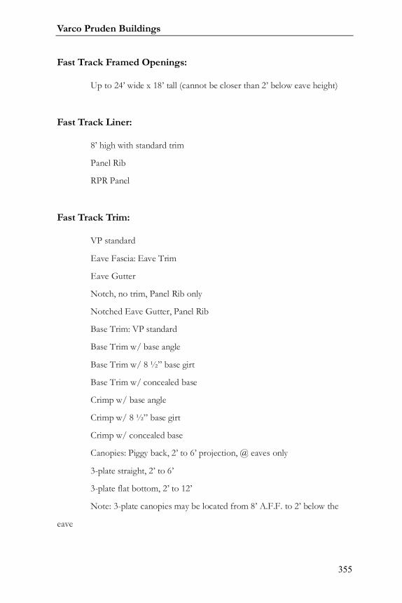
Varco Pruden Buildings
355
Fast Track Framed Openings:
Up to 24’ wide x 18’ tall (cannot be closer than 2’ below eave height)
Fast Track Liner:
8’ high with standard trim
Panel Rib
RPR Panel
Fast Track Trim:
VP standard
Eave Fascia: Eave Trim
Eave Gutter
Notch, no trim, Panel Rib only
Notched Eave Gutter, Panel Rib
Base Trim: VP standard
Base Trim w/ base angle
Base Trim w/ 8 ½” base girt
Base Trim w/ concealed base
Crimp w/ base angle
Crimp w/ 8 ½” base girt
Crimp w/ concealed base
Canopies: Piggy back, 2’ to 6’ projection, @ eaves only
3-plate straight, 2’ to 6’
3-plate flat bottom, 2’ to 12’
Note: 3-plate canopies may be located from 8’ A.F.F. to 2’ below the
eave
Systems Guide
356
Fast Track Insulation:
Standard options
Fast Track Accessories
Accessories: Same as in VP Command

Varco Pruden Buildings
357
Notes:

Systems Guide
358
Varco Pruden Buildings
359
How to Price a VP Building9
Five Pricing Methods
There are two methods you can use to fully estimate a VP Building in
your office.
1. - For simple buildings, we provide the VP Fast Track pricing system,
accessible online, within Order Entry.
2. - For other buildings, you should utilize VP's proprietary VP
Command software leased by your firm. Based upon your level of expertise, you
may be able to model many varied structures onto VP Command in your office.
Running the building file you have created in your office, you will be able to
generate estimates, preliminary drawings and preliminary engineering data.
The final three methods involve the partial or complete involvement of
VP's Estimating Group.
3. - The third method is a shared effort, initiated by you, the builder,
inputting the project into VP Command in your office and then transmitting the
file to VP Estimating for assistance in completing the quote. This method is the
most frequently used of the five shown here and requires you to fax or e-mail the
VPC Quote Request form, along with the OCF Standard Questions forms.
9 By Dave Cleary

Systems Guide
360
4. - Sometimes a design/build project is complex and modeling the
project onto VP Command is simply beyond your level of expertise. In this case,
we ask you to send sketches, drawings, VP's Price Confirmation request sheets
along with the OCF Standard Questions form to VP Estimating. VP Estimating
can complete quotations for complex design/build projects. We will work closely
together with you and your team using our best value-engineering skills to
generate a complete estimate.
5. - If a design professional has prepared Plans and Specifications for a
project which clearly shows all of the environmental loads, building geometry,
and other parameters required for the project, VP Estimating can complete the
estimate. As in method 4, we ask that you send the VP Price Confirmation
request sheets and the OCF Standard Questions form with the drawings and
specifications.
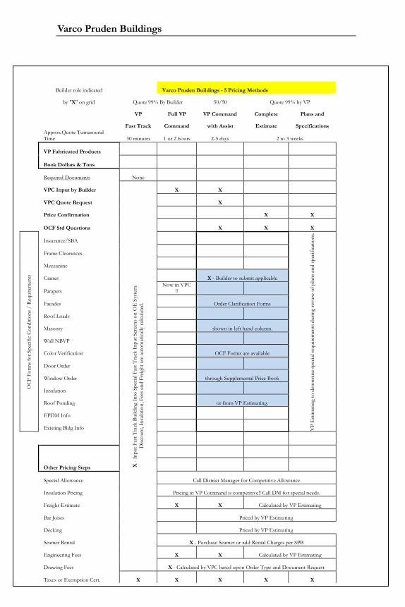
Varco Pruden Buildings
361
Builder role indicated Varco Pruden Buildings - 5 Pricing Methods
by "X" on grid Quote 99% By Builder 50/50 Quote 99% by VP
VP Full VP VP Command Complete Plans and
Fast Track Command with Assist Estimate SpecificationsApprox.Quote TurnaroundTime 30 minutes 1 or 2 hours 2-5 days 2 to 3 weeks
VP Fabricated Products
Book Dollars & Tons
Required Documents None
VPC Input by Builder
X -
Inpu
t Fas
t Tra
ck B
uild
ing
Into
Spe
cial F
ast T
rack
Inpu
t Scr
eens
on
OE
Sys
tem
. D
iscou
nt, I
nsul
atio
n, F
ees a
nd F
reig
ht a
re a
utom
atic
ally
calc
ulat
ed.
X X
VPC Quote Request X
Price Confirmation X X
OCF Std Questions X X X
OC
F Fo
rms f
or S
pecif
ic C
ondi
tions
/ R
equi
rem
ents
Insurance/SBA
VP
Est
imat
ing
to d
eter
min
e spe
cial
requ
irem
ents
dur
ing
revi
ew o
f plan
s and
spec
ifica
tions
.
Frame Clearances
Mezzanine
Cranes X - Builder to submit applicable
ParapetsNow in VPC
!!
Facades Order Clarification Forms
Roof Loads
Masonry shown in left hand column.
Wall NBVP
Color Verification OCF Forms are available
Door Order
Window Order through Supplemental Price Book
Insulation
Roof Ponding or from VP Estimating.
EPDM Info
Existing Bldg Info
Other Pricing Steps
Special Allowance Call District Manager for Competitive Allowance
Insulation Pricing Pricing in VP Command is competitive!! Call DM for special needs.
Freight Estimate X X Calculated by VP Estimating
Bar Joists Priced by VP Estimating
Decking Priced by VP Estimating
Seamer Rental X - Purchase Seamer or add Rental Charges per SPB
Engineering Fees X X Calculated by VP Estimating
Drawing Fees X - Calculated by VPC based upon Order Type and Document Request
Taxes or Exemption Cert. X X X X X

Systems Guide
362
Notes:

Varco Pruden Buildings
363
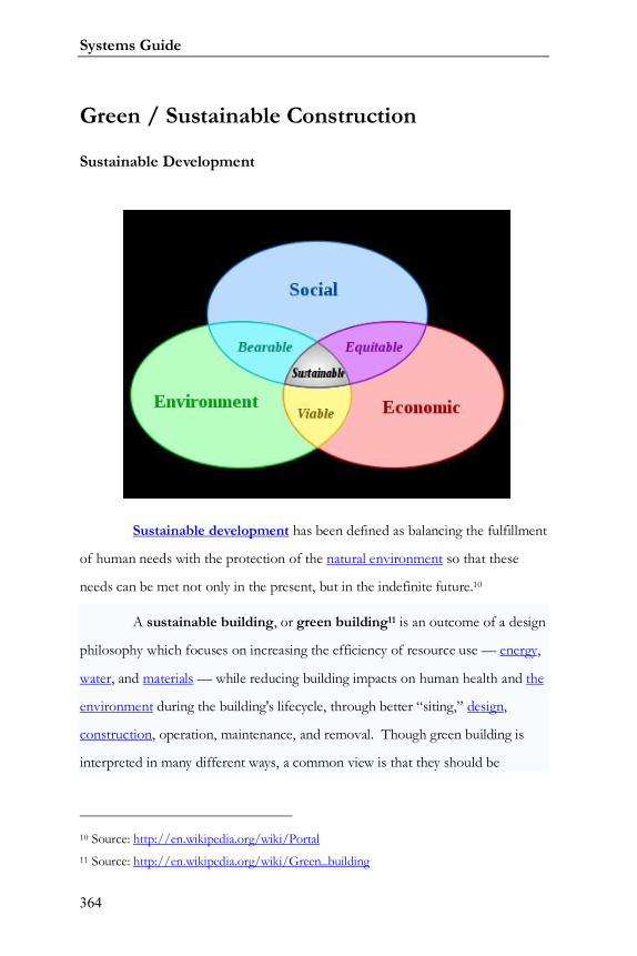
Systems Guide
364
Green / Sustainable Construction
Sustainable Development
Sustainable development has been defined as balancing the fulfillment
of human needs with the protection of the natural environment so that these
needs can be met not only in the present, but in the indefinite future.10
A sustainable building, or green building11 is an outcome of a design
philosophy which focuses on increasing the efficiency of resource use — energy,
water, and materials — while reducing building impacts on human health and the
environment during the building's lifecycle, through better “siting,” design,
construction, operation, maintenance, and removal. Though green building is
interpreted in many different ways, a common view is that they should be
10 Source: http://en.wikipedia.org/wiki/Portal11 Source: http://en.wikipedia.org/wiki/Green_building
Varco Pruden Buildings
365
designed and operated to reduce the overall impact of the built environment on
human health and the natural environment by:
Efficiently using energy, water, and other resources
Protecting occupant health and improving employee
productivity
Reducing waste, pollution and environmental degradation
USGBC
The U.S. Green Building Council (USGBC) defines green building as
“…those that incorporate design and construction practices that significantly
reduce or eliminate the negative impact of buildings on the environment and
occupants in five broad areas12”:
1. Sustainable site planning
2. Safeguarding water and water efficiency
3. Energy efficiency and renewable energy
4. Conservation of materials and resources
5. Indoor environmental quality
LEED expands this definition to include “Innovation of Design” or
“Innovation in Operations” to include items that go above and beyond the basic
12 Source: Yudelson, Jerry. Green Building A to Z. New Society Publishers. 2007. Canada.
Systems Guide
366
green building principles such as: green educational programs; green cleaning;
green power purchasing; construction waste management; etc. Having a LEED
certified professional on your project can help you immensely in achieving the
desired certifications.
LEED v3.0 credit categories and their point distribution are:
Sustainable Sites (SS) – 26 possible points
Water Efficiency (WE) – 10 possible points
Energy & Atmosphere (EA) – 35 possible points
Material & Resources (MR) – 14 points
Indoor Environmental Quality EG) – 15 possible points
Innovation in Operations (IO) – 6 possible points
Regional Priority (RP) – 4 possible points
In order to design a building that can be certified as a green building
under LEED (Leadership in Energy and Environmental Design) several
factors/activities must be incorporated into the design. Those factors and
activities are listed below:
Sustainable Sites
Building should not be developed on prime farmland, land
located near the 100-year flood plain, land located within 100 feet of a
Varco Pruden Buildings
367
wetland, or on existing public parkland. Building should be developed,
preferably, within existing urban areas to preserve green spaces and reduce
urban sprawl. Ideally, the building should be developed on cleaned up and
rehabilitated brown-fields.
Orient the building to reduce heat loss in the winter and heat
gain in the summer. Use plantings to block wind and direct sunlight.
Site disturbance should be kept to a minimum. Buildings with
small footprints are preferred.
Maintain existing vegetation located more than 40 feet from
the building or 5 feet from roadways and walkways. If the site was
previously developed, minimize paving and add green areas on the building
site.
Minimize storm water runoff. Provide a means to filter the
runoff through plants and settling basins before it is discharged to sewer.
Reduce outdoor light pollution by specifying shields on
outdoor lighting.
Water Efficiency
Specify natural landscaping that requires little to no artificial
irrigation. If irrigation is required, specify drip irrigation.
Systems Guide
368
Reduce domestic water use by specifying water conserving
toilets, urinals, and showers.
Capture and use rainwater for irrigation, makeup to cooling
towers, and washing cars.
If local building codes permit, consider using rainwater to flush
toilets.
Energy and Atmosphere
Have the building commissioned by a designated
Commissioning Authority.
Energy performance of the building must meet or exceed the
American Society of Heating, Refrigerating, and Air Conditioning Engineers
(ASHRAE) Standard 90.12.
No chlorofluorocarbon (CFC) containing equipment
permitted in the building.
When practical, use renewable energy resources like solar,
wind, and biomass13.
13 Biomass, a renewable energy, is biological material derived from living, or recentlyliving organisms, such as wood, waste, and alcohol fuels
Varco Pruden Buildings
369
Reduce or eliminate the use of hydrochlorofluorocarbon
(HCFC) containing equipment.
Provide a means to measure ongoing energy and water
consumption.
When practical, buy electric power from a green power
provider (wind farm).
Indoor Environmental Quality
Building design must comply with ASHRAE Standard 623 and
ASHRAE Standard 554.
No smoking in the building.
Carbon dioxide can be monitored to measure ventilation
effectiveness.
Design must insure good ventilation effectiveness.
Contractor must develop and follow an indoor air quality
management plan during construction.
Specify building materials that emit little to no volatile organic
compounds (VOC).
Systems Guide
370
Indoor chemical pollution sources must be isolated and their
emissions exhausted.
Building occupants should have a high degree of control over
their environment including views/daylight from outdoors.
Materials and Resources
An area in the building must be designated for the storage and
collection of recyclables.
It is preferred to reuse materials from existing buildings.
Recycle 50 to 75% of the construction waste.
When practical, specify salvaged material.
Specify materials with recycled content.
Specify materials that are located within 500 miles of the site.
Specify rapidly renewable materials like bamboo, pine, and
wheat grass.
Use only wood grown on tree farms that use certified
practices.

Varco Pruden Buildings
371

Systems Guide
372
Notes:

Varco Pruden Buildings
373
Notes:

Systems Guide
374
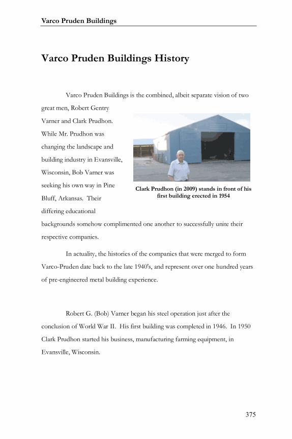
Varco Pruden Buildings
375
Varco Pruden Buildings History
Varco Pruden Buildings is the combined, albeit separate vision of two
great men, Robert Gentry
Varner and Clark Prudhon.
While Mr. Prudhon was
changing the landscape and
building industry in Evansville,
Wisconsin, Bob Varner was
seeking his own way in Pine
Bluff, Arkansas. Their
differing educational
backgrounds somehow complimented one another to successfully unite their
respective companies.
In actuality, the histories of the companies that were merged to form
Varco-Pruden date back to the late 1940's, and represent over one hundred years
of pre-engineered metal building experience.
Robert G. (Bob) Varner began his steel operation just after the
conclusion of World War II. His first building was completed in 1946. In 1950
Clark Prudhon started his business, manufacturing farming equipment, in
Evansville, Wisconsin.
Clark Prudhon (in 2009) stands in front of hisfirst building erected in 1954
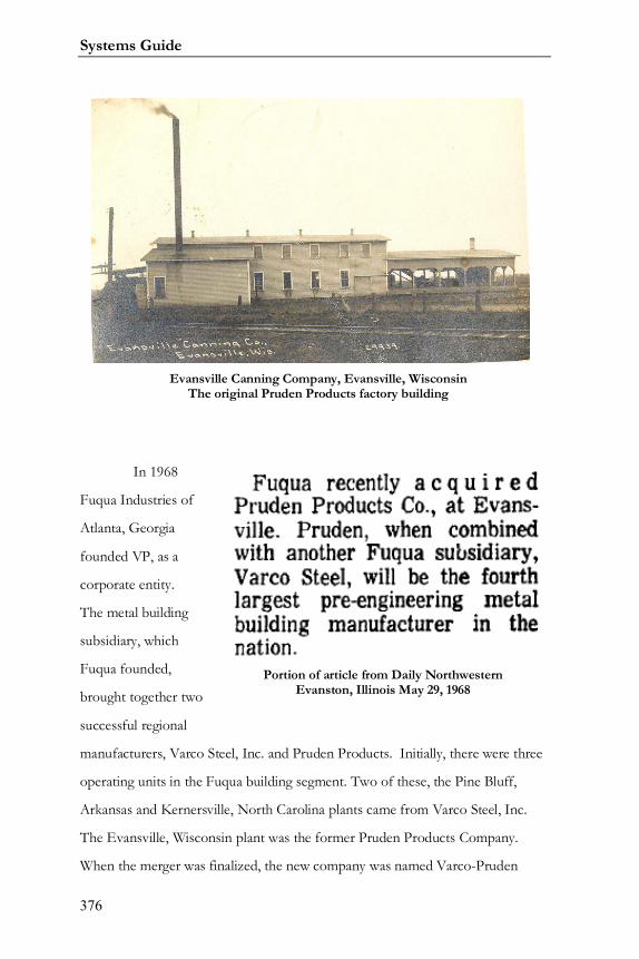
Systems Guide
376
In 1968
Fuqua Industries of
Atlanta, Georgia
founded VP, as a
corporate entity.
The metal building
subsidiary, which
Fuqua founded,
brought together two
successful regional
manufacturers, Varco Steel, Inc. and Pruden Products. Initially, there were three
operating units in the Fuqua building segment. Two of these, the Pine Bluff,
Arkansas and Kernersville, North Carolina plants came from Varco Steel, Inc.
The Evansville, Wisconsin plant was the former Pruden Products Company.
When the merger was finalized, the new company was named Varco-Pruden
Evansville Canning Company, Evansville, WisconsinThe original Pruden Products factory building
Portion of article from Daily NorthwesternEvanston, Illinois May 29, 1968

Varco Pruden Buildings
377
Buildings.
Within a year
Varco-Pruden
took steps to
achieve a national
market presence
adding a fourth
plant on the west
coast. The plant
in Turlock,
California gave
VP a presence in all major markets. As a result of its quality products, enhanced
capacity, and Custom Concept, VP experienced phenomenal growth. It was so
successful, in fact, that it came to the attention of other companies in the
construction industry who wished to expand their operations. Dombrico, Inc.,
the U.S. subsidiary of Dominion Bridge of Montreal, Canada, acquired Varco-
Pruden in 1971.
This acquisition was
Dominion Bridge's
first significant
incursion into the
United States by
Dominion Bridge's
U.S. subsidiary,
Dombrico, Inc.
Varco-Pruden was purchased from Fuqua Industries, Inc., and had annual sales
of about $25 million. Just three years later, in 1974, Dombrico, Inc. changed its
Varco Pruden - St. Joseph, Missouri
Varco Pruden – Evansville, Wisconsin
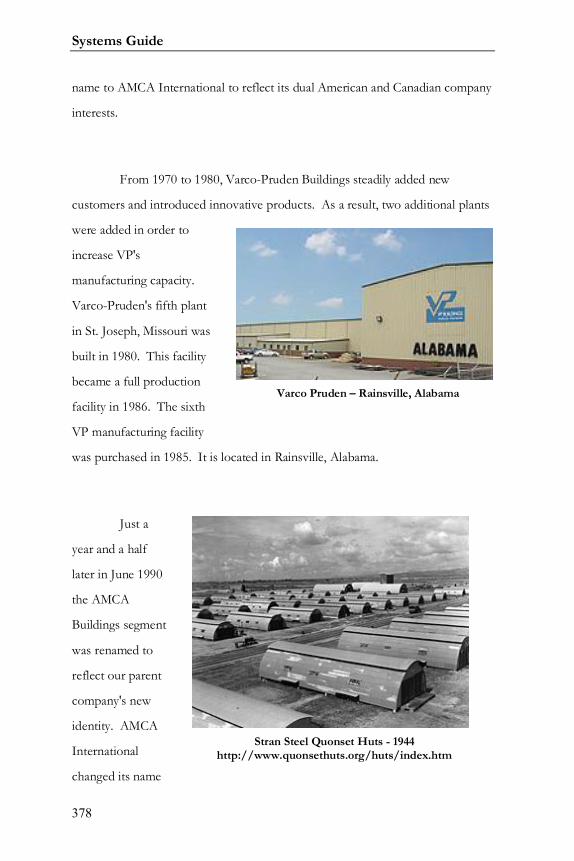
Systems Guide
378
name to AMCA International to reflect its dual American and Canadian company
interests.
From 1970 to 1980, Varco-Pruden Buildings steadily added new
customers and introduced innovative products. As a result, two additional plants
were added in order to
increase VP's
manufacturing capacity.
Varco-Pruden's fifth plant
in St. Joseph, Missouri was
built in 1980. This facility
became a full production
facility in 1986. The sixth
VP manufacturing facility
was purchased in 1985. It is located in Rainsville, Alabama.
Just a
year and a half
later in June 1990
the AMCA
Buildings segment
was renamed to
reflect our parent
company's new
identity. AMCA
International
changed its name
Varco Pruden – Rainsville, Alabama
Stran Steel Quonset Huts - 1944http://www.quonsethuts.org/huts/index.htm
Varco Pruden Buildings
379
to United Dominion Industries Limited and VP became a United Dominion
Company. In April 1991, Stran Buildings, a sister United Dominion Company,
was consolidated with Varco-Pruden to increase VP's size, operating base, and
resources. The move added two manufacturing facilities, one in LaGrange,
Georgia, and one in Van Wert, Ohio. Both facilities have since been shut down.
Stran had operated as a major provider of building systems for 54 years, having
designed and produced the Quonset Hut, famed during World War II. Beginning
as the Stran-Steel Service Center of Great Lakes Steel in 1937, National Steel
Corporation owned Stran until 1983 when AMCA International purchased most
of its assets.
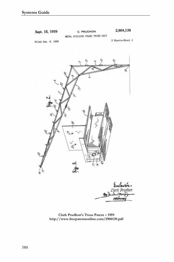
Systems Guide
380
Clark Prudhon’s Truss Patent – 1959http://www.freepatentsonline.com/2904139.pdf
Varco Pruden Buildings
381
The year 1992 saw the release of VP Command, VP’s revolutionary
building design system. VP has always been ahead of the competition regarding
its computer systems and VP Command launched the company even further
ahead.
In 1997, The LTV Corporation, a publicly owned company, purchased
Varco-Pruden Buildings at that time changed its name to VP Buildings, Inc. LTV
(originally standing for Ling, Temco, & Voight), the third largest U.S. steel maker,
was a fully integrated steel producer and the second largest domestic supplier of
flat rolled steel for the automotive, appliance and electrical markets. LTV formed
a new wholly owned subsidiary into which VP Buildings and AEP-Span in Dallas,
TX were placed. This new subsidiary was called VP Buildings, Inc. The VP
Components Group was located in Dallas, TX and began in 1999 as an exclusive
component suppler for VP Builders and is considered a branch of VP Buildings,
Inc.
In 1998, VP Buildings, Inc. acquired United Panel Inc., which produces
Fiberstone panel systems exclusively for VP Builders and located in Mt. Bethel,
Pennsylvania. This product line was sold through the VP Components Group.
In 2000, VP Buildings, Inc. signed a Joint venture with Trache Tee to
provide nested Tee hangers for VP Buildings, Inc. Builders and also purchased
Graham FRP Composites Ltd. of Inglewood, Ontario, Canada.
Systems Guide
382
The year 2000 also saw the creation of VP University (VPU) – Varco
Pruden training department. Under the direction of Dr. Edward C. Champagne
VPU formalized functional training as well as enhanced the training options
available to our builder family. Today, VPU conducts training seminars
throughout North America along with many world-wide joint venture efforts.
On September 19, 2001 GRUPO IMSA of Monterrey, Mexico acquired
VP Buildings Inc. GRUPO IMSA was founded over sixty years ago as Industrias
Monterrey. Its productive activities were mostly oriented to the Mexican
marketplace, establishing a leadership position in the manufacture and
distribution of galvanized steel sheet production and products for the
construction and packaging industries. Today GRUPO IMSA has productive
activities in Mexico, but also in the United States, Argentina, Chile, Brazil,
Venezuela, and Guatemala, and exports to the five continents.
Grupo IMSA was broken into four major components: Enermex -
Batteries and Auto parts; Imsalum - Aluminum Products; Imsatec - Steel and
Plastic Products; and IMSA Acero – Steel Processed Products. VP Buildings,
Inc. became part of Imsatec Division. While AEP Span, United Panel, and FRP
Graham were combined with Imsatec’s other like businesses to better service
North America.
In 2007 Ternium of Argentina acquired Grupo IMSA's assets, including
Varco Pruden Buildings, Inc.

Varco Pruden Buildings
383
The most recent chapter in VP’s storied history began in February 2008
when it was purhcased from Ternium by BlueScope North America.14 BlueScope
is headquartered in Austrailia.
In October of 2009 Varco Pruden opened Varco Pruden Roof
Systems15 to specifically give independent authorized Varco Pruden builders
assistance with roofing products and pricing. The team, located in Memphis, will
work exclusively on roofing; with focus on re-roof, retrofit, and new
conventional construction projects
14 http://memphis.bizjournals.com/memphis/stories/2008/01/28/daily37.html15
http://steelguru.com/news/index/2009/10/01/MTE0MTk2/Varco_Pruden_launches_new_business_unit_exclusively_for_roofing.html
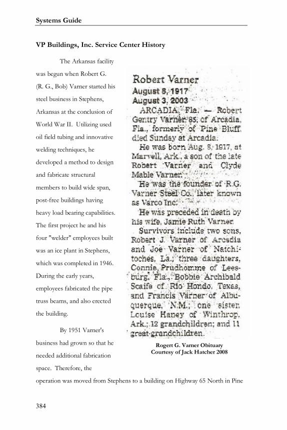
Systems Guide
384
VP Buildings, Inc. Service Center History
The Arkansas facility
was begun when Robert G.
(R. G., Bob) Varner started his
steel business in Stephens,
Arkansas at the conclusion of
World War II. Utilizing used
oil field tubing and innovative
welding techniques, he
developed a method to design
and fabricate structural
members to build wide span,
post-free buildings having
heavy load bearing capabilities.
The first project he and his
four "welder" employees built
was an ice plant in Stephens,
which was completed in 1946.
During the early years,
employees fabricated the pipe
truss beams, and also erected
the building.
By 1951 Varner's
business had grown so that he
needed additional fabrication
space. Therefore, the
operation was moved from Stephens to a building on Highway 65 North in Pine
Rogert G. Varner ObituaryCourtesy of Jack Hatcher 2008
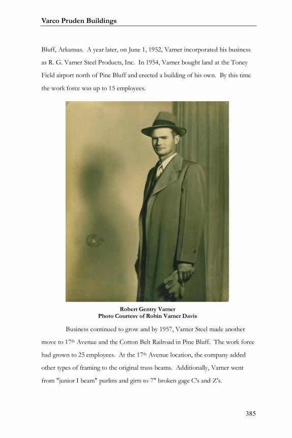
Varco Pruden Buildings
385
Bluff, Arkansas. A year later, on June 1, 1952, Varner incorporated his business
as R. G. Varner Steel Products, Inc. In 1954, Varner bought land at the Toney
Field airport north of Pine Bluff and erected a building of his own. By this time
the work force was up to 15 employees.
Business continued to grow and by 1957, Varner Steel made another
move to 17th Avenue and the Cotton Belt Railroad in Pine Bluff. The work force
had grown to 25 employees. At the 17th Avenue location, the company added
other types of framing to the original truss beams. Additionally, Varner went
from "junior I beam" purlins and girts to 7" broken gage C's and Z's.
Robert Gentry VarnerPhoto Courtesy of Robin Varner Davis
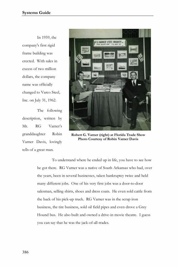
Systems Guide
386
In 1959, the
company's first rigid
frame building was
erected. With sales in
excess of two million
dollars, the company
name was officially
changed to Varco Steel,
Inc. on July 31, 1962.
The following
description, written by
Mr. RG Varner’s
granddaughter Robin
Varner Davis, lovingly
tells of a great man.
To understand where he ended up in life, you have to see how
he got there. RG Varner was a native of South Arkansas who had, over
the years, been in several businesses, taken bankruptcy twice and held
many different jobs. One of his very first jobs was a door-to-door
salesman, selling shirts, shoes and dress coats. He even sold cattle from
the back of his pick-up truck. RG Varner was in the scrap iron
business, the tire business, sold oil field pipes and even drove a Grey
Hound bus. He also built and owned a drive-in movie theatre. I guess
you can say that he was the jack-of-all-trades.
Robert G. Varner (right) at Florida Trade ShowPhoto Courtesy of Robin Varner Davis
Varco Pruden Buildings
387
He never backed down from an opportunity, so when a friend
asked him if he could buy some oil field pipe and put together steel
trusses to frame a building, he accepted, and that is where it all began.
In 1948, he began building metal buildings around the area, eventually
starting RG “Bob” Varner Steel Products, Inc. He did lose money on
one of his first jobs, but that would be the last. His next big project was
to build a brick plant in Holly Springs, Mississippi using the oil field
pipe. It was a success and in a short time, Varner Steel was building
brick plants east of the Rockies from Kansas to Maine.
RG Varner moved his company to Pine Bluff, Arkansas in
1956 and continued to grow his business. He became a pilot making it
easier for him to do business. As his business grew to larger cities, he
began to run into restrictions on local building codes. This is a story
worth mentioning. One job, in Richmond, Virginia almost got the best
of him. He was being filed with an injunction that was going to force
him to take down a building that was already built. He challenged them
to load the building to the code requirement. RG Varner suggested that
bricks be placed on the roof and that if there were any kind of failure or
deflection, he would remove the entire building. But the best thing,
showing his true personality, was that he offered to personally sit in a
rocking chair under the loaded roof through the entire test. What
happened next was typical of how he approached everything, television
cameras, reporters, and bystanders watched in amazement as this crazy
man sat in his rocking chair reading the morning paper while each brick
was being added. Well, the building didn’t fall and there was no
deflection. From this point, the company became known as Varco-
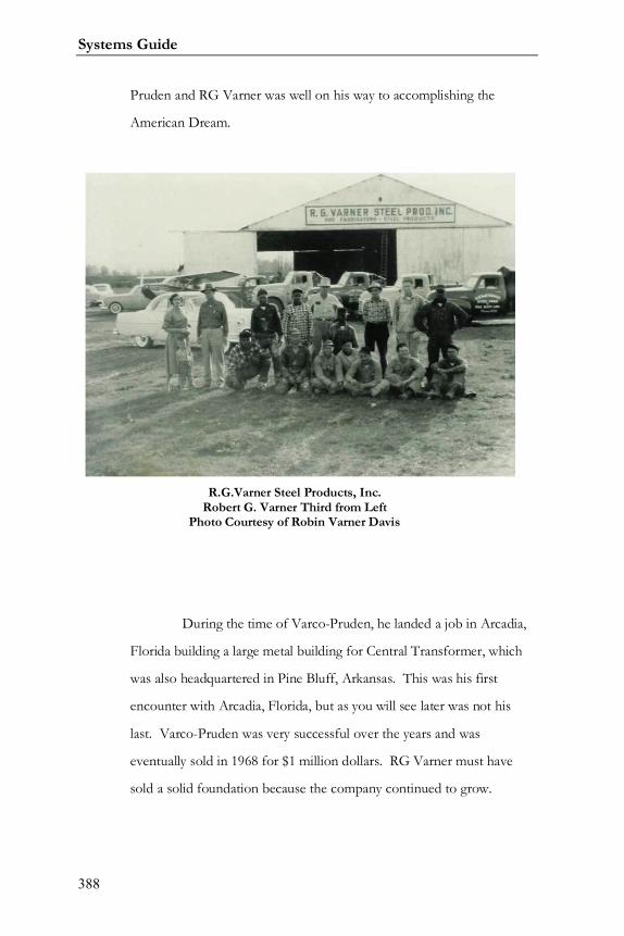
Systems Guide
388
Pruden and RG Varner was well on his way to accomplishing the
American Dream.
During the time of Varco-Pruden, he landed a job in Arcadia,
Florida building a large metal building for Central Transformer, which
was also headquartered in Pine Bluff, Arkansas. This was his first
encounter with Arcadia, Florida, but as you will see later was not his
last. Varco-Pruden was very successful over the years and was
eventually sold in 1968 for $1 million dollars. RG Varner must have
sold a solid foundation because the company continued to grow.
R.G.Varner Steel Products, Inc.Robert G. Varner Third from Left
Photo Courtesy of Robin Varner Davis
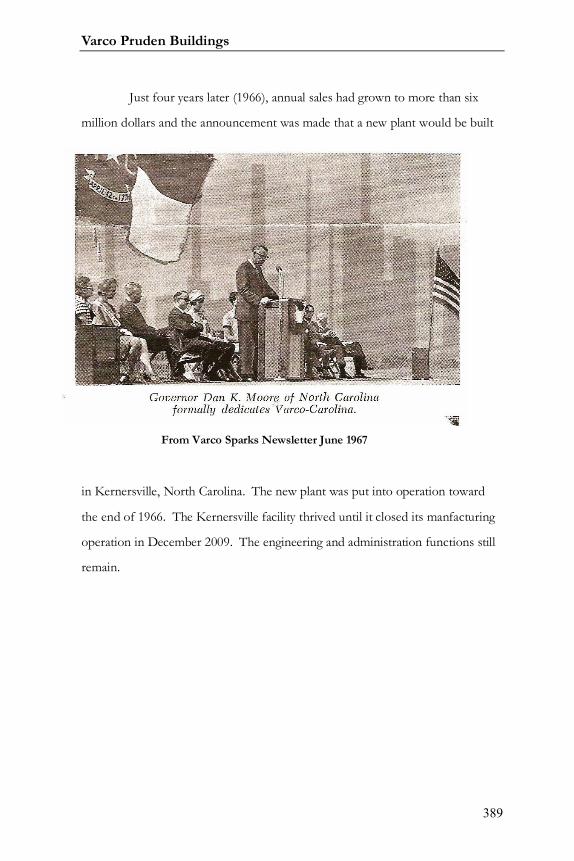
Varco Pruden Buildings
389
Just four years later (1966), annual sales had grown to more than six
million dollars and the announcement was made that a new plant would be built
in Kernersville, North Carolina. The new plant was put into operation toward
the end of 1966. The Kernersville facility thrived until it closed its manfacturing
operation in December 2009. The engineering and administration functions still
remain.
From Varco Sparks Newsletter June 1967

Systems Guide
390
In 2009 BlueScope began converting its familial facilities into BlueScope
Manufacturing operations. The first such fully functional is in Visalia, California.
The conversion continues with plans for completion in 2011.
Varco Steel, Inc. 1967From Varco Sparks Newsletter June 1967
Varco-carolina FacilityFrom Varco-Sparks Newsletter June 1967
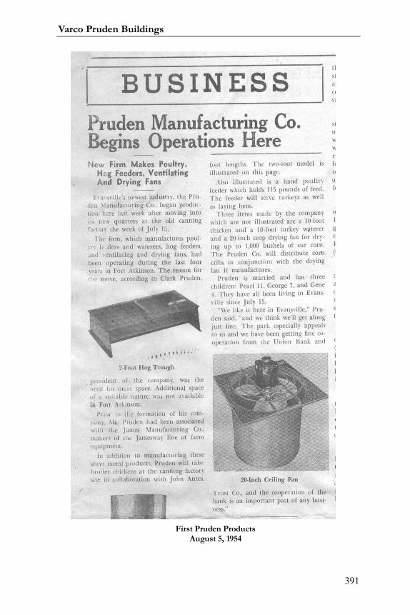
Varco Pruden Buildings
391
First Pruden ProductsAugust 5, 1954
Systems Guide
392
ThThe Evansville, Wisconsin service center was established in 1950, by
Clark Prudhon. Originally incorporated in Fort Atkinson, Wisconsin, Pruden
Products (changed to Pruden to reflect the phonetic pronunciation) manufactured
poultry feeders and ventilation fans for the farm industry. The company quickly
outgrew its initial facility. In 1954 the company purchased a 20,000 square foot
building, which had previously housed the Fall River Canning Company and
relocated to Evansville, Wisconsin.
During the summer of 1954, Pruden Products delivered its first steel
building frames to a local farmer. They were designed to be used with wood
purlins and girts. Others buildings closely followed this first venture into the
buildings industry. By early 1963, the company offered an all steel building with
purlins, girts, and panel rib roofing and siding. The year 1963 also saw several
plant expansions including the addition of a 10,000 square foot office building.
Total manufacturing, warehousing, and office area exceeded 75,000 square feet at
this time. Pruden Products continued its steady growth. Within three years,
additional space was added.
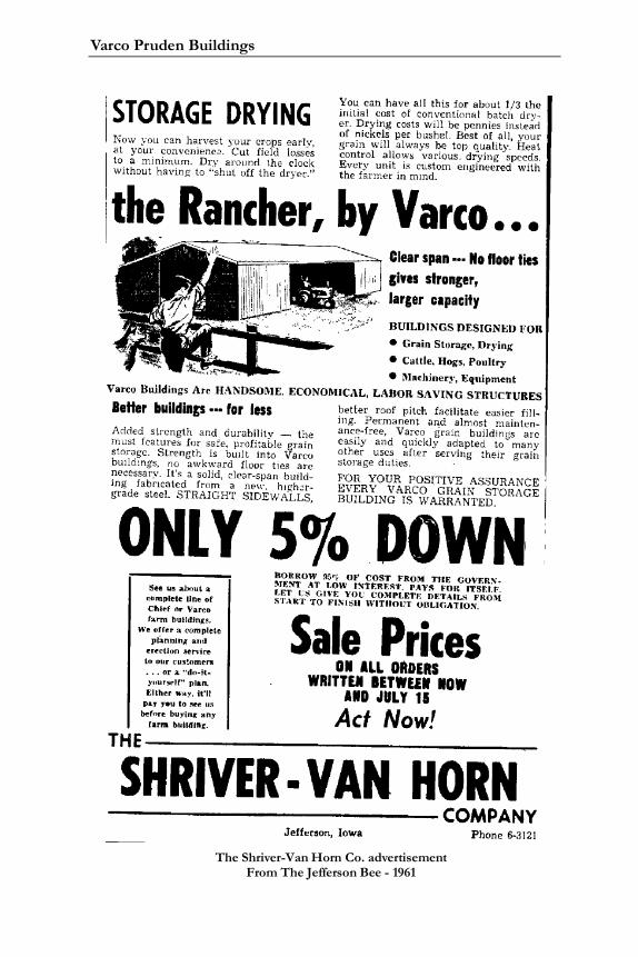
Varco Pruden Buildings
393
The Shriver-Van Horn Co. advertisementFrom The Jefferson Bee - 1961
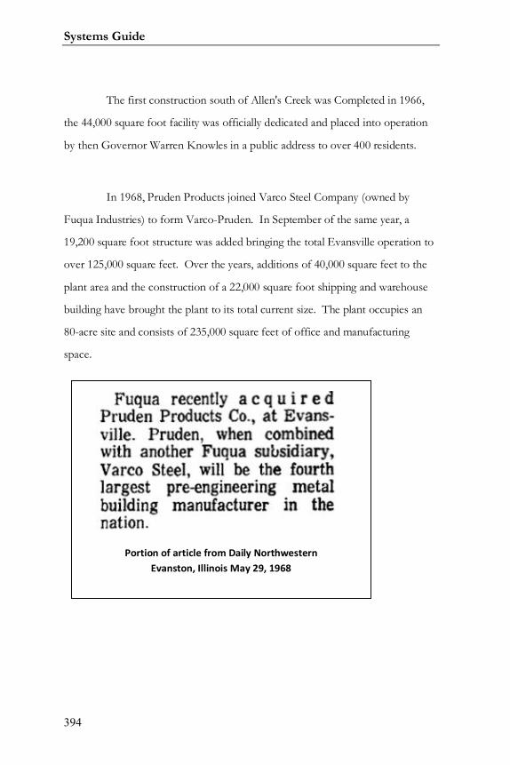
Systems Guide
394
The first construction south of Allen's Creek was Completed in 1966,
the 44,000 square foot facility was officially dedicated and placed into operation
by then Governor Warren Knowles in a public address to over 400 residents.
In 1968, Pruden Products joined Varco Steel Company (owned by
Fuqua Industries) to form Varco-Pruden. In September of the same year, a
19,200 square foot structure was added bringing the total Evansville operation to
over 125,000 square feet. Over the years, additions of 40,000 square feet to the
plant area and the construction of a 22,000 square foot shipping and warehouse
building have brought the plant to its total current size. The plant occupies an
80-acre site and consists of 235,000 square feet of office and manufacturing
space.
Portion of article from Daily NorthwesternEvanston, Illinois May 29, 1968
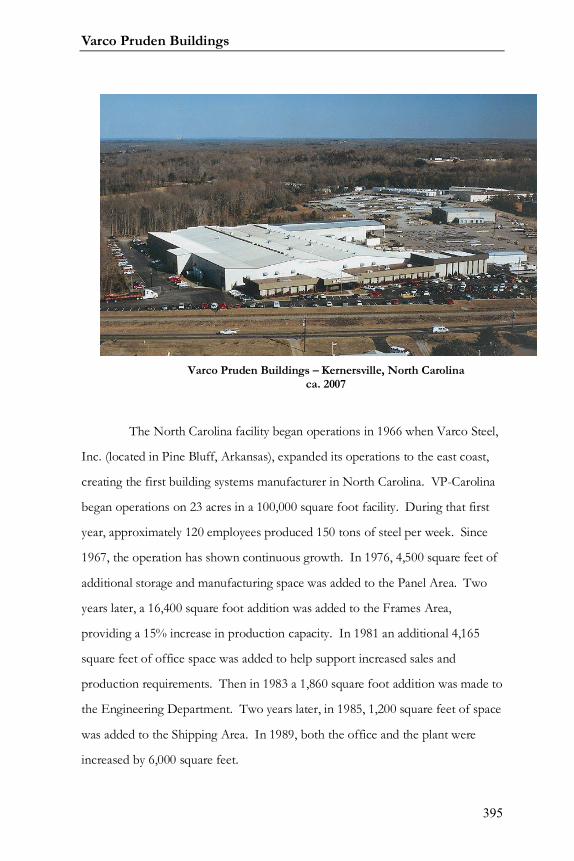
Varco Pruden Buildings
395
The North Carolina facility began operations in 1966 when Varco Steel,
Inc. (located in Pine Bluff, Arkansas), expanded its operations to the east coast,
creating the first building systems manufacturer in North Carolina. VP-Carolina
began operations on 23 acres in a 100,000 square foot facility. During that first
year, approximately 120 employees produced 150 tons of steel per week. Since
1967, the operation has shown continuous growth. In 1976, 4,500 square feet of
additional storage and manufacturing space was added to the Panel Area. Two
years later, a 16,400 square foot addition was added to the Frames Area,
providing a 15% increase in production capacity. In 1981 an additional 4,165
square feet of office space was added to help support increased sales and
production requirements. Then in 1983 a 1,860 square foot addition was made to
the Engineering Department. Two years later, in 1985, 1,200 square feet of space
was added to the Shipping Area. In 1989, both the office and the plant were
increased by 6,000 square feet.
Varco Pruden Buildings – Kernersville, North Carolinaca. 2007
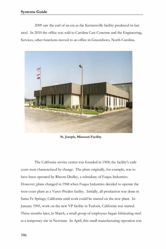
Systems Guide
396
2009 saw the end of an era as the Kernersville facility produced its last
steel. In 2010 the office was sold to Carolina Cast Concrete and the Engineering,
Services, other functions moved to an office in Greensboro, North Carolina.
The California service center was founded in 1968; the facility's early
years were characterized by change. The plant originally, for example, was to
have been operated by Rheem-Dudley, a subsidiary of Fuqua Industries.
However, plans changed in 1968 when Fuqua Industries decided to operate the
west coast plant as a Varco-Pruden facility. Initially, all production was done in
Santa Fe Springs, California until work could be started on the new plant. In
January 1969, work on the new VP facility in Turlock, California was started.
Three months later, in March, a small group of employees began fabricating steel
at a temporary site in Newman. In April, this small manufacturing operation was
St. Joseph, Missouri Facility
Varco Pruden Buildings
397
moved to another location in south Turlock. Finally, in May, the entire operation
was moved to the Turlock site. By the end of June, the 140,000 square foot
facility was fully enclosed and the first beams were being manufactured. Within a
year, all administrative operations were consolidated at the Turlock location with
the completion of the main office building. In 1977, the first of four additions
was completed, adding 2,700 square feet. In 1981 and 1985, the service center
added an additional 6,400 square feet of warehousing area to better serve
Builders. Similarly, nearly 10,000 square feet of painting area and other additions
were added in 1982 and 1988 to improve quality levels and the facility's ability to
be responsive to customers' needs.
The end of 1990 added another 2,400 square foot addition added to
accommodate the growing technical staff. This latest addition brought total
office space to 17,800 square feet. Overall, the original 140,000 square feet
located on 18 acres has grown to nearly 160,000 since 1969.
The Service Center enjoys a centralized location in the San Joaquin
Valley and grew from a handful of employees to become a major employer in the
area. By 1994, the facility had grown to employ over 260 people on two shifts
with production capacity in excess of 800 tons per week. The California Service
Center had grown to become the dominant building systems manufacturer in the
western U.S. Approximately 200 authorized VP Builders are served by the
Center.
In 1980, the Missouri facility was built. This initial construction
consisted of 65,200 square feet of building, which housed solid web production.

Systems Guide
398
Phase I also marked the introduction of the newest manufacturing technology to
Varco-Pruden. Phase II construction was started in August 1984 and consisted
of a 52,585 square foot addition to the original facility. This expansion houses
roll-forming equipment for roof and wall panel, and secondary framing. Full-line
production began in July 1985. Completion of the Phase II expansion brought
the Missouri facility to a total of 147,485 square feet of manufacturing and office
space on a 19-acre site.
In the forty years since R. G. Varner established his business, Varco-
Pruden has become an active leader and innovator in the commercial
construction industry. As a result of the ever-increasing sales volume in the East,
the Rainsville, Alabama Manufacturing Plant was purchased by AMCA in 1984
and assigned to the North Carolina Service Center for increased manufacturing
capacity. This facility is located on 23 acres and provides 116,000 square feet of
Varco Pruden – Rainsville, Alabamaca. 2007
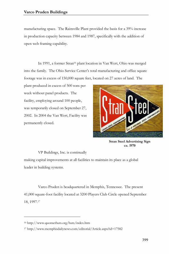
Varco Pruden Buildings
399
manufacturing space. The Rainsville Plant provided the basis for a 39% increase
in production capacity between 1984 and 1987, specifically with the addition of
open web framing capability.
In 1991, a former Stran16 plant location in Van Wert, Ohio was merged
into the family. The Ohio Service Center’s total manufacturing and office square
footage was in excess of 150,000 square feet, located on 27 acres of land. The
plant produced in excess of 500 tons per
week without panel products. The
facility, employing around 100 people,
was temporarily closed on September 27,
2002. In 2004 the Van Wert, Facility was
permanently closed.
VP Buildings, Inc. is continually
making capital improvements at all facilities to maintain its place as a global
leader in building systems.
Varco Pruden is headquartered in Memphis, Tennessee. The present
41,000 square-foot facility located at 3200 Players Club Circle opened September
18, 1997.17
16 http://www.quonsethuts.org/huts/index.htm17 http://www.memphisdailynews.com/editorial/Article.aspx?id=17582
Stran Steel Advertising Signca. 1970
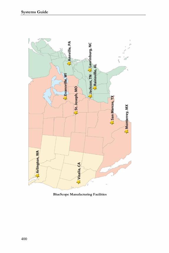
Systems Guide
400
BlueScope Manufacturing Facilities
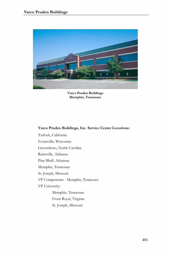
Varco Pruden Buildings
401
Varco Pruden Buildings, Inc. Service Center Locations:
Turlock, California
Evansville, Wisconsin
Greensboro, North CarolinaRainsville, Alabama
Pine Bluff, Arkansas
Memphis, Tennessee
St. Joseph, MissouriVP Components - Memphis, Tennessee
VP University:
Memphis, TennesseeFront Royal, Virginia
St. Joseph, Missouri
Varco Pruden BuildingsMemphis, Tennessee

Systems Guide
402
Notes:
Varco Pruden Buildings
403
Conclusion
This manual is designed to assist you in becoming an expert on the
many ways to approach a project. Two things to remember when designing and
estimating a project are:
1. Find out the customer’s specific needs on a project.
2. Apply the products in a creative way to achieve the project’s
objectives.
By identifying your customer’s wants and needs, you will understand the
true project goals, which will create a unique advantage over your competition.
This edge can win you the project.
Another purpose of this manual is to give tips on how to determine a
project’s needs before you pitch the project to the owner. First, you must discuss
the product applications with the owner or specifier in order to determine what
and how the VP products will be used.
The more questions that are asked and answered on the front-end will
determine how the project proposal is structured. The VP Buildings’ product line
is one of the most versatile in the industry and can be adapted to suit the project’s
specific needs.
We hope that this manual is a useful tool for our Builders in the process
of selling, designing and estimating projects. If you have any questions
concerning any applications in this manual, please contact your VP Service
Systems Guide
404
Center. With your customer-focused proposal and VP’s superior performance,
we can create The Ultimate Building Solution for your customer.
Disclaimer:
The examples and illustrations in this manual are intended to support
the discussion topic and in some cases may not be accurate for a condition being
considered. They are generally true, but can always be found to not cover some
given situation. They have been developed with particular loadings, dimensions,
and codes, and are accurate for the situation intended. The charts showing
percentages are meant to be approximate or to show the trend of the subject
rather than an exact number for all.
With the many variables in construction: loading; geometry; customer
preference; etc. it is often difficult to state that “If A is done, then B will result.”
Therefore you should take advantage of the power of VPCommand and the
experts within Varco Pruden Buildings to create varying building project
scenarios for your customer.

Varco Pruden Buildings
405
Notes:

Systems Guide
406
Notes:

Varco Pruden Buildings
407
Notes:

Systems Guide
408
Notes:

Varco Pruden Buildings
409
Systems Guide
410
Index
(NIA) 404
Insulation ....................... 218
“ALONG” wall
frame locations ...... 334, 335
“Frame Line” Numbers
VPC ................................ 334
“Frame” Numbers
VPC ................................ 334
“LEFT” point
frames ........................... 334
1 5/8”
inset girts ................. 19, 142
1/16" ............................. 16, 68
10”
secondary . 19, 138, 142, 354
Secondary ...................... 137
10-year wind ....................... 47
11 ½”
secondary ......... 19, 142, 354
Secondary................. 87, 137
20.5”
truss purlins ................... 150
22 gage
panel ......176, 180, 189, 195,200, 202, 205
24 gage
panel ......180, 189, 195, 200,202
29.5”
truss purlins ................... 150
50-year wind ....................... 47
7”
secondary . 19, 140, 142, 354
Secondary.. 46, 87, 137, 155,219
8 ½”
secondary ................. 19, 138
Secondary............... 137, 355

Varco Pruden Buildings
411
accessories . 107, 202, 226, 260,261, 282, 327
Accessories
Fast Track .......................356
Accessory .... 252, 260, 261, 327
acrylic coating
secondary.......................135
Additional Weights ..............53
AEP-Span ................... 237, 381
along
wall for frames ...............334
Alternate Span Live
loading .............................48
AMCA International............378
angle
Bracing ... 122, 126, 137, 155,355
anti-capillary ...... 176, 186, 194
anti-capillary bead...... 176, 186
Apex 20 Vents....................262
approximate weights............51
architectural standing seamroof
SLRII ............................... 176
arenas .................................. 90
ASHRAE....... 216, 223, 368, 369
Insulation ....................... 216
asterisk
Reports .......................... 340
asterisks
VPC ................................ 318
ASTM Hot Box .................... 223
Attachments ........................ 28
VPC Tree ........................ 325
Auxiliary Live
loading ............................. 49
bar joist . 89, 91, 135, 137, 150,151, 174, 176, 270
Bar Joist ..............151, 180, 271
Bare frame deflection .......... 46
Bare Frame Drift .................. 46
Base of Wall
Trim ....................... 240, 241
Systems Guide
412
base trim ............ 195, 200, 202
bay spacing ...... 66, 70, 71, 108,136, 137, 153, 154, 155
Bay Spacing ............ 19, 66, 154
biomass ............................. 368
blanket insulation ......218, 219,229
BlueScope Manufacturing .. 390
bracing12, 45, 47, 87, 107, 118,122, 124, 126, 127, 154, 162,210, 211, 316
Bracing ...... 118, 122, 123, 124,126, 252, 316, 353
VPC Tree ........................ 326
bracing between endposts
Post and Beam ................. 87
bridge weight
Crane ............................. 107
British Thermal Units ......... 224
Bronze
primer ........................... 135
BTU ........................... 224, 225
Building Code . 35, 57, 353, 354
building code official ........... 51
building code officials .......... 41
Building codes ..................... 54
Building Editor .................. 304
VPC................. 318, 338, 340
Building End Use ................. 36
Building Energy Conservation ...................................... 223
building line...... 19, 20, 31, 142
building use .................. 36, 352
Building Use ........................ 36
Built Up Slope Structural .... 348
Built-up Canopy .................. 28
C
secondary 41, 107, 154, 155,225, 277, 282, 283, 284,348, 382, 385
cab operated
Crane ............................. 108
canopies ... 28, 32, 33, 262, 282,283, 325, 327, 355
canopy ................... 28, 29, 318
cantilevered ........................ 30

Varco Pruden Buildings
413
cantilevers
canopy .............................28
Carrier
jack beam .......................294
Category "B" Items
MBMA Complexity . 282, 283
Category "C" Items
MBMA Complexity .........283
Category "D" Items
MBMA Complexity . 283, 284
CB-1
Frames ............... 71, 75, 352
Ceiling .................... 35, 50, 151
ceiling tiles ................. 136, 152
channel purlin braces .........140
chlorofluorocarbon ............368
Clark Prudhon ............ 375, 392
classification
Crane .............................107
clearance .... 15, 18, 23, 66, 151
Clearances ..................... 15, 23
Clearspan ............................ 67
Coating Membranes
Insulation ....................... 229
Codes .............. 35, 45, 353, 354
collateral ... 38, 39, 41, 152, 153
Collateral
loading ...... 35, 39, 40, 48, 50
collateral load .............. 39, 153
Collateral Load ..................... 39
collateral loading ................. 39
collateral loads.. 38, 39, 41, 152
Collateral loads .............. 35, 50
Color ...................171, 172, 317
Colors
VPC ........................ 316, 318
Column .. 68, 73, 81, 82, 84, 96,124, 127, 128
column base .................. 46, 66
column depth
Frames ................. 70, 82, 83
common wall
Systems Guide
414
VPC Openings ................ 166
communication.................... 12
Competitive Allowance ...... 281
Conclusion ................... 75, 403
concrete ............... 45, 129, 287
condensation ...... 226, 227, 228
Condensation ..... 226, 227, 228
Conduction ........................ 224
construction schedule .......... 14
continuous
Secondary . 18, 154, 155, 162
Continuous Beam .... 67, 71, 76,78, 87, 294
Continuous girts ................ 154
Continuous Truss .... 67, 76, 78,93, 95, 294
Controls Heat flow ............. 215
Controls Noise ................... 215
Convection ........................ 224
Conventional
construction ... 270, 271, 276
corner zones ...................... 152
corrosive ............ 136, 137, 153
covering 89, 137, 151, 153, 166,171, 210
Covering .....166, 171, 172, 173,252
VPC Tree ........................ 327
Crane .... 47, 107, 108, 109, 253
crane data ......................... 107
Crane Optimization Concepts ...................................... 107
Crane Service Classifications ...................................... 112
Crane ............................. 107
cranes .......... 84, 107, 108, 125
Cranes .......................... 50, 107
VPC Tree ........................ 326
customer requirements ....... 12
Cyan
VPC......................... 316, 317
daylight
green building ............... 370
Dead
loading ................. 43, 48, 49
Varco Pruden Buildings
415
dead load .............................43
Dead loads ...........................43
Deck Frame ........ 270, 271, 272
default
VPC .................... 93, 94, 166
Default
VPC ... 33, 308, 313, 314, 318
defaults
VPC ................ 312, 313, 314
Definitions and Background
Deflection ........................46
deflection35, 45, 46, 50, 57, 58,91, 107, 154
Deflection ................ 45, 46, 57
Deflection Criteria ................45
Dektites .............................263
Design Professional .............13
diagonal bracing .................120
diaphragm.................... 46, 353
Disclaimer ...................... 8, 404
discrete bracing..................140
Dombrico, Inc .................... 377
Dominion Bridge ................ 377
door hardware ................... 260
doors .............. 66, 91, 162, 260
downspouts ....................... 236
Dr. Edward C. Champagne .. 382
Drawings .............304, 312, 328
VPC ......... 252, 317, 318, 338
drift .................. 45, 46, 50, 107
dwg
VPC ................................ 338
dxf
VPC ................................ 338
eave height .. 15, 16, 23, 24, 72,75, 125, 142, 311, 313, 325,332, 355
Eave Height .................... 23, 25
economy 41, 66, 70, 71, 76, 87,90, 135, 136, 295
edge zones ......................... 152
Edit Check
VPC ........................ 318, 340
Systems Guide
416
embossed .................. 199, 200
End bay spacing ................... 19
end bays ...................... 76, 152
End Frames ................... 68, 78
end post .............................. 87
endbay ........................ 19, 153
Endwall .................. 31, 68, 330
Energy & Atmosphere
LEED .............................. 366
Energy and Atmosphere .... 368
Engineer of Record ........ 51, 55
Engineering Content
VPC ........................ 319, 321
environmental degradation 365
Equipment ............... 15, 16, 50
Essential facilities................. 36
Essential Facilities (Hospitals,Fire, Police…)
Building Use ..................... 36
Estimates ................... 343, 345
Evansville, Wisconsin .375, 376,392, 401
existing building ... 44, 328, 338
exposed fastener roofs ........ 57
Exposure “B” ....................... 41
Exposure “C” ....................... 41
exterior columns .... 66, 71, 353
façade ............................31, 32
Façade ....... 28, 31, 32, 252, 291
Facades ...................... 291, 295
Face bolted ......................... 84
Factory Mutual ........... 135, 152
Fast Track ...352, 353, 354, 355,356
fiberglass insulation ........... 223
financing ............................. 14
fixed base .......................70, 82
Fixed base
Frames .......................70, 82
Fixed Base
Wind Post ...................... 127
Windpost ....................... 127
fixed clip ..................... 140, 179
fixed clip location
Varco Pruden Buildings
417
SSR .................................179
flange brace .......................162
flange braces ........ 98, 154, 211
flange bracing .............. 98, 211
Flange Bracing ......................98
flashing . 28, 189, 261, 262, 263
Flexible Membranes
Insulation .......................228
Floor Live
loading .............................48
floor vibrations .....................54
FM
Factory Mutual . 14, 135, 152
FP-12..................................205
FP-12 Soffit Panel ...............205
Frame Load Sharing ..............47
Frame Optimization .............66
Frame Span
Frames .............................82
Frame Types.........................85
Framed opening .................154
Framed Openings ...... 162, 242,261, 326, 355
frames ... 12, 18, 24, 47, 71, 76,82, 87, 90, 91, 93, 118, 124,137, 210, 334, 335
Frames ... 66, 70, 71, 82, 87, 90,126, 127, 316, 334, 352, 353
VPC Tree ........................ 325
framing .. 20, 29, 33, 48, 66, 75,87, 91, 96, 135, 136, 142,152, 153, 205, 211, 226, 261,262, 263, 295, 304, 326, 385,398, 399
Freight ....................... 281, 345
Freight Calculator ............... 345
From-To Reference Points
VPC ................................ 332
Fuqua Industries .376, 394, 396
Future ................. 14, 50, 51, 87
future expansion ................ 118
G-30 galvanized
secondary ...................... 135
Gable ..................... 21, 22, 352
gable roof slopes
Systems Guide
418
Roof ................................. 18
Gable Slope ......................... 21
galvalume .................... 31, 348
Galvalume .......... 176, 180, 195
Galvanized coating............. 153
General Information ............ 13
VPC Tree ........... 68, 312, 325
geometry .. 8, 15, 291, 338, 404
Geometry ............... 15, 16, 352
VPC Tree . 311, 312, 313, 325
girt.... 32, 67, 87, 137, 154, 155,162, 218, 355
governing code .............. 35, 38
Graphics Pane ............ 306, 307
VPC ........ 309, 318, 322, 323
Gray
primer ........................... 135
green
construction .................. 364
Green / SustainableConstruction .................. 364
green building .... 364, 365, 366
Green-From ....................... 332
Greensboro, North Carolina ............................... 396, 401
Ground snow ....................... 43
GRUPO IMSA ..................... 382
gutter ................................ 237
Gutters .............................. 236
half-load
Frames ............................ 87
half-load frame .................... 78
Hall of Fame ...................... 347
hangars ..........................90, 91
headers .............. 154, 261, 326
heat conductance .............. 226
heat gain ........................... 367
heat loss ............................ 367
heat transfer ..................... 224
Heat transfer ..................... 224
Heat Transfer Fundamentals ...................................... 224
Help
VPC......................... 338, 343
Varco Pruden Buildings
419
hierarchical .........................307
hierarchy
VPC Tree........................307
High Eave
Trim ...............................245
Hips and valleys ...................23
Hips and Valleys ........... 23, 296
horizontal clearances ..... 15, 84
horizontal drift ... 43, 70, 72, 82
Horizontal drift ... 42, 70, 72, 82
Horizontal Drift ....................46
Hot Box test
Insulation .......................217
How to Price a VP Building .359
humidity .................... 227, 229
hurricane prone ...................41
HVAC...................... 35, 50, 217
Hybrid ........................ 276, 277
hydrochlorofluorocarbon ...369
Hylar 5000... 176, 180, 189, 202
I-120
Factory Mutual............... 152
I-60
Factory Mutual............... 152
I-75
Factory Mutual............... 152
I-90
Factory Mutual............... 152
Image Archive .................... 347
Importance Factors .............. 38
Indoor Environmental Quality
LEED....................... 366, 369
Innovation in Operations
LEED....................... 365, 366
in-place testing
Insulation ....................... 216
in-place value
Insulation ............... 217, 223
in-place values
Insulation ....................... 217
In-Place Values
Insulation ....................... 217
Systems Guide
420
in-place weights................... 51
Input
Reports 24, 25, 311, 318, 340
Input Report
VPC ................................ 318
inset
Secondary ......... 32, 154, 354
inset girt ...................... 19, 142
Inset girts............................. 18
Insulation .. 183, 186, 214, 215,218, 222, 223, 272, 327, 356
Interactive Frame Design 24, 91
Interior bay spacing ............. 19
interior bays ........................ 76
interior column .. 40, 66, 71, 72,76, 79, 80, 81, 93, 96, 152,153
interior columns 48, 67, 70, 71,72, 76, 80, 89, 93, 95, 107,118, 334, 353
Interior Frames ............. 68, 76
Irregular shapes ................... 23
Jack Beam ............................ 89
Jack Beams ................... 89, 294
Jack Trusses ....................... 294
jambs ......................... 261, 326
Kernersville, North Carolina ............................... 376, 389
KXL ..... 172, 174, 176, 180, 189,195, 199, 200, 202, 236, 267
Kynar 500 (KXL) ................. 176
LaGrange, Georgia ............. 379
laminated
Insulation ....... 218, 223, 229
lateral ....................... 46, 47, 58
Lateral Deflection ................ 46
Layers ................................ 331
Lean –to .............................. 89
Lean-to ..................... 50, 51, 89
ledger angle ...................... 100
LEED ........................... 365, 366
Left-Clicking
in Tree ........................... 322
length ..... 15, 16, 18, 20, 66, 80,108, 142, 153, 189, 311, 313,325, 334
Varco Pruden Buildings
421
lighting . 66, 90, 91, 94, 95, 152,215, 367
Lighting .................. 35, 50, 215
lighting and sprinklers ..........91
Lime Green
VPC ................................317
liner ..... 98, 137, 155, 210, 211,257
Liner .... 33, 151, 210, 211, 257,355
VPC Tree ........................327
Liner Panel .........................172
Ling, Temco, & Voight
LTV Steel ........................381
Live load ...............................38
Load Definition Summary .....48
load-bearing
masonry ................... 66, 100
Loading 35, 45, 50, 51, 57, 109,152, 153
VPC Tree ........................325
Loads ..... 38, 40, 41, 44, 45, 50,352
louvers 162, 260, 261, 262, 282
Low Eave
Trim ....................... 243, 244
Low Hazard- Agricultural
Building Use ..................... 36
Low Rise Buildings .... 47, 55, 57
LTV Corporation ................. 381
Magenta
VPC ................................ 317
mansard
Facade ..................... 31, 291
masonry ..... 44, 45, 71, 98, 100,118, 129, 136, 154, 166, 282,283, 327
Masonry ..... 100, 154, 171, 252
Material & Resources
LEED............................... 366
Materials and Resources .... 370
MBMA ..................47, 282, 283
MBMA Complexity - Complex ...................................... 283
MBMA Complexity - Factor 283
Systems Guide
422
MBMA Complexity - Medium ...................................... 282
MBMA Complexity - Simple 282
Measurement of Heat Transfer ...................................... 224
Memphis, Tennessee . 399, 401
metal building systems ...... 227
Metal Buildings Manfacturer’sAssociation (MBMA)Complexity..................... 282
Metal Deck ........................ 271
mezzanine .... 43, 287, 288, 295
Mezzanine ................. 253, 287
mezzanines ................ 118, 125
Mezzanines ............... 287, 295
Modular .............................. 67
module
SSR ................. 175, 182, 183
module strip
SSR ........................ 182, 183
moisture ............. 226, 227, 228
Mt. Bethel, Pennsylvania ... 381
multi-gutter ......................... 31
NAIMA 202-96
Insulation ............... 218, 223
Net Accessories ................. 261
NIA 404 ............................. 223
No smoking
green building ............... 369
non-metal roofing
with deck frame............. 270
open walls ........................... 41
Open Web .......... 66, 90, 91, 96
open web frame .................. 94
opening ......118, 162, 166, 313,326
Opening OptimizationConcepts ................ 162, 166
openings 87, 91, 123, 126, 135,136, 152, 154, 162, 260, 287
Openings .................... 166, 171
VPC................................ 327
VPC Tree ........................ 326
Optima .............................. 267
order clarification form ..... 107
Varco Pruden Buildings
423
Order Clarification form .....153
Order Clarification Forms....345
Order Entry ........ 267, 343, 359
Order Entry System ............343
Order/Estimate ClarificationForms ............................343
Orders ................................343
Orientation ........................331
Other Topics............... 287, 295
outset
Secondary .. 18, 32, 136, 154,354
Outset ................................154
outset girts ........... 19, 136, 142
Owners' PreventativeMaintenance Manual ........345
Panel Rib 33, 89, 137, 150, 151,171, 172, 176, 180, 185, 186,194, 195, 199, 202, 218, 262,263, 308, 313, 318, 354, 355
Panel Rib Roof ... 171, 176, 185,186, 308
parapet .......................... 31, 32
Parapet .................. 28, 31, 291
Parapets ............................ 291
Parent Dialog
View Button ................... 331
Part Status
VPC Tree ........................ 328
partial height portal frame . 129
Partial Height Rods ............ 123
partially open walls .............. 41
partition..................... 124, 295
partitions ..................... 57, 295
Partitions ................... 292, 295
Parts Status
VPC ................................ 338
pendant
Crane ............................. 108
perm
insulation ........222, 228, 229
perm rating .........222, 228, 229
Piggyback ............................. 28
Piggyback canopies .............. 29
Piggyback canopy ................ 28

Systems Guide
424
Pine Bluff, Arkansas ...375, 376,385, 387, 388, 395, 401
pinned ................................. 87
pipe ... 66, 73, 80, 264, 384, 387
point ....152, 227, 321, 334, 366
polyurethane foam ............ 208
Portal
Bracing ... 126, 127, 353, 364
portal brace ....................... 126
portal frame .............. 123, 124
Post and Beam ..................... 87
PR ........171, 243, 244, 282, 313
covering .......... 176, 195, 327
Pre-Assembled
doors ............................. 262
Prevents Condensation ...... 215
Pricing ........ 267, 281, 318, 340
Report 16, 22, 137, 312, 328,359
VPC Tree ........................ 328
pricing folder ...................... 319
primary frame offset ............ 19
Primary Frame Offset .......... 19
primary framing ... 19, 103, 142
Product Optimization .......... 11
Product Seminar .................. 76
Products from Varco PrudenRoof Systems include
VP Roofing .................... 348
Pruden Products . 376, 392, 394
purlin ................... 67, 218, 219
purlin bearing edge ........... 176
Purlin Channel Bracing ...... 317
purlins .. 48, 100, 103, 120, 137,138, 140, 150, 174, 176, 180,282, 385, 392
Secondary...... 30, 33, 87, 89,135, 137, 152, 354
purpose 12, 210, 260, 267, 287,403
Quote Assistance ................ 345
Quote Request ................... 345
R
Insulation ...... 218, 219, 223,225, 347
Radiation .......................... 224
Varco Pruden Buildings
425
Rafter .................... 68, 84, 270
Rain
loading .............................49
Rainsville, Alabama ... 378, 398,401
Rake ................. 28, 29, 30, 245
rake extension .....................30
Rake Extension .....................29
Rake or Roof extension ........29
Reactions ...........................340
Reports ..........................328
Read-me File ......................304
recycled content ................370
Red
VPC ........................ 316, 332
Red Oxide
primer ............................135
reducible live load ................38
reductions
live load ................... 39, 224
refresh
VPC .......................... 11, 323
renewable energy ...... 365, 368
renewable materials .......... 370
Reports
VPC .................316, 318, 340
VPC Tree ........................ 328
Retrofit and Re-roof Solutions
VP Roofing ..................... 348
reuse materials .................. 370
reverse-rolled
panel .............................. 202
Reviewing Drawings andDetails
VPC ................................ 317
RF
Frames ................. 70, 75, 87
ridge .......................... 260, 352
Ridge .......... 246, 247, 248, 331
Ridge Ventilators ............... 263
Rigid
Frames ..... 70, 87, 90, 93, 94,352, 353
Systems Guide
426
rigid board insulation . 180, 189
rigid frame ........ 40, 85, 89, 386
Rigid Frame ................... 67, 81
Rigid Frame Truss ................ 67
Robert G. Varner................ 375
Robin Varner Davis ............ 386
rod anchor ......................... 123
rod bracing ................ 120, 282
rods
Bracing ........... 123, 126, 210
Rods .......................... 124, 353
Roof . 13, 15, 18, 21, 29, 43, 70,82, 135, 137, 152, 153, 171,172, 174, 218, 219, 250, 251,252, 291, 317, 331, 352, 354
Roof Covering Specifications ...................................... 177
roof curbs .......................... 260
Roof Curbs ........................ 264
Roof Expansion .................. 298
Roof height Change ............. 21
roof height changes ....... 21, 44
Roof Live
loading ............................ 48
Roof Openings ................... 152
roof pitch ...... 16, 18, 66, 71, 90,125, 171
Roof Pitch ......................15, 18
roof secondary ........... 150, 154
roof slope ..................... 57, 291
roof snow ............................ 43
RPR .................... 202, 354, 355
Rt 225
RTU (Roof Top Units) ......... 152
Rubber Roofing ................. 272
R-value ....................... 180, 189
sag angles .......................... 140
Salmon
VPC................................ 316
salvaged material .............. 370
saturated ........................... 227
Seamer ....................... 281, 345
seat depths ....................... 150
Varco Pruden Buildings
427
secondary .... 12, 18, 28, 70, 76,135, 136, 137, 152, 153, 154,155, 162, 166, 172, 316, 338
Secondary .. 135, 136, 137, 153,154, 252, 316, 354
VPC Tree ........................326
Secondary Framing ...............69
Secondary lap.....................139
Secondary lap dimensions ..139
Secondary Offset ................142
Section
VPC ........... 47, 128, 223, 332
SEDs ............ 239, 252, 253, 318
seismic 44, 45, 47, 58, 126, 154,352
Seismic
loading ....................... 44, 48
seismic zone .........................44
semi-concealed .......... 199, 202
Service Center ............ 108, 345
serviceability . 47, 50, 54, 55, 58
Serviceability 47, 54, 55, 56, 57,58, 109
serviceability problems ........ 54
shape ........ 13, 44, 83, 335, 338
Shear Walls ........................ 129
Sidewall ............................. 330
single slope ......... 15, 18, 21, 82
Single Slope ............. 18, 21, 22
Single slope frames ............ 102
single slopes
Roof ................................. 18
Site Drainage ................. 15, 18
Site location ................... 35, 50
skewed
walls .... 22, 23, 30, 282, 283,284
Skewed
walls .................... 15, 22, 23
skewed walls ........................ 22
Skewed walls ................. 15, 22
Skewed Walls ..................... 297
SLR II ...................176, 188, 189
SLR II clip ............................ 176

Systems Guide
428
SLR Roof ........................... 348
SMACNA
Trim ............................... 237
Snow
loading................ 43, 48, 352
snow exposure .................... 44
snow load ................. 38, 43, 90
Snow Load ........................... 43
Snow loads .......................... 43
sock
VPC Tree ....................... 308
socks
VPC Tree ............... 307, 308
soffit ......... 28, 30, 33, 257, 327
Soffit......................... 28, 32, 33
solar .................................. 368
Soldier Columns
Framing ......................... 103
solid web
framing ..... 68, 282, 294, 397
Solid Web ...................... 66, 96
SP 172, 211
SP finish............................. 172
spandrel beams ................. 131
Special Occupancy Structures
Building Use .................... 36
specifications .... 13, 42, 54, 55,216, 223
sporting complexes ............. 90
sprinkler ......... 41, 95, 136, 152
Sprinkler .............................. 35
SSR 89, 137, 151, 152, 171, 172,174, 175, 177, 179, 180, 182,183, 184, 218, 219, 263, 281,282, 308, 313, 318, 327, 328,348, 354
SSR clip .............................. 174
SSR Expansion ................... 184
SSR module strip ............... 182
SSR Module Strip ............... 182
SSR panels ......................... 174
SSR roof............................. 175
SSR Roof
VP Roofing .................... 348
Varco Pruden Buildings
429
SSR Staggered Endlap .........184
St. Joseph, Missouri .... 378, 401
stability
Post and Beam .................87
Staggered End Laps
SSR .................................180
standard colors
covering .. 172, 205, 211, 354
standard dimensioning .........16
Standard Erection Details .. 239,318
Standard OccupancyStructures
Building Use .....................36
Standing Seam .... 57, 152, 171,172, 174, 313
Standing Seam roofs ............57
Steel building systems ..........12
Stephens, Arkansas ............384
storm water runoff .............367
Straight Column
Frames ....................... 83, 84
straight columns . 83, 85, 93, 94
Stran Buildings ................... 379
Stran-Steel ......................... 379
Strapping ........................... 152
strength . 54, 55, 120, 142, 180,189, 195, 200, 202, 272
Strength ............................... 54
Structural failure .................. 54
Structural Membranes
Insulation ....................... 228
Super Block ........................ 175
Superblock
SSR ................................. 183
with SSR ......................... 180
SuperBlock ................. 219, 223
supermarket columns
Frames ............................. 83
Supplemental Price Book .. 153,262, 264, 267, 345
sustainable building .......... 364
Sustainable development .. 364
Sustainable Development .. 364
Systems Guide
430
Sustainable Sites ................ 366
tapered
framing .... 66, 68, 83, 84, 93,94, 270
tapered column
Frames ............................. 83
Tapered Column
Frames ............................. 83
tapered columns ....... 83, 93, 94
Temperature
loading............................. 49
Temporary Bracing ............ 130
Ternium ..................... 382, 383
Texture Clad ...................... 206
TextureClad ....................... 206
The Graphics Pane ............. 309
The Ultimate Building Solution ................................ 12, 404
thermal block
SSR ................................ 183
Thermal Block ............ 175, 218
Thermal blocks
with SSR ................. 180, 189
Thermal Blocks .................. 176
Thermal Clad ..................... 208
Thermal conductance ....... 225
thermal expansion ...... 176, 189
Thermal resistance ........... 225
Thermal transmittance ..... 225
ThermalClad ...................... 208
Thermoplastic Polyolefin ... 272
three-plate ......... 66, 73, 79, 80
tilt walls............................... 44
Tool Bar ............................. 343
Toolbar ............... 308, 322, 323
top bolted ........................... 84
Top running cranes
Crane ............................. 108
Torsional ........................... 124
Transfer ...................... 224, 343
Tree .................... 306, 307, 308
VPC................. 322, 323, 331
Tree Tips
Varco Pruden Buildings
431
VPC ................................322
Trim ... 172, 232, 236, 239, 240,241, 242, 243, 244, 245, 246,247, 248, 249, 250, 251, 252,257, 316, 327, 355
trim conditions ... 236, 237, 239
trolley weight
Crane .............................107
Truss Beam ..........................94
Truss Purlin ........................150
Truss purlins .......................150
tube ................... 66, 71, 73, 80
tube column .........................71
Tuf Lites ..................... 261, 263
Tuff-Dome .........................263
Turlock, California ..... 377, 396,401
turned
interior column ................79
U
Insulation 216, 223, 225, 365
UL-25 flame spread ............263
underhung crane
Crane ............................. 108
Unibeam .............................. 85
UniBeam .............................. 85
Updating Defaults ............. 314
User
VPC Tree ........................ 327
USGBC ............................... 365
U-value
Insulation ............... 216, 225
Van Wert, Ohio .......... 379, 399
vapor retarder ... 222, 226, 228,229
Vapor retarders ................. 228
Vapor Retarders ................. 228
Varco Pruden Buildings . 4, 375,382, 401, 404, 442
Varco Pruden Roof Systems348,383
Varco Steel.. 376, 386, 394, 395
Varco-Pruden ..... 375, 376, 378,379, 381, 388, 394, 396, 398
Systems Guide
432
Varco-Pruden Buildings..... 377,378, 381
Vee Rib . 33, 194, 199, 200, 218,262, 263, 354
Vee Rib Wall .............. 199, 200
ventilation ............ 91, 228, 369
vents .. 162, 260, 261, 262, 282,327
vertical bolting ..................... 84
View
VPC ........................ 330, 331
Visalia, California ............... 390
visible condensation .......... 227
volatile organic compounds369
Vp Builder Site
Websites ........................ 347
VP Command 12, 23, 33, 39, 44,45, 53, 75, 96, 126, 152, 153,166, 257, 261, 262, 277, 287,296, 297, 303, 304, 305, 307,320, 322, 325, 338, 343, 344,345, 356, 359, 360, 381
VP Components ......... 260, 347
VP District Manager ........... 223
VP Estimating Department .. 41
VP Fast Track .................... 359
VP Marketing..................... 347
VP Product Seminar ........... 344
VP Roofing ......................... 348
VP Service center................. 45
VP Service Center ....... 152, 153
VP University .. 4, 312, 318, 382
VP.Com ............................. 346
VPC
VP Command25, 44, 84, 166,171, 252, 281, 304, 311,313, 314, 316, 317, 318,325, 326, 327, 338, 340,344, 359
VPC Defaults ...................... 313
VPC Input Basics ................ 311
VPCommand ..8, 16, 22, 33, 80,81, 84, 137, 142, 166, 252,281, 295, 304, 305, 306, 307,308, 311, 316, 318, 323, 324,334, 338, 340, 344, 404
VPCommand Building Editor ...................................... 305
Varco Pruden Buildings
433
VPCommand Tree andGraphics Pane View ........306
VPCommand Tree Description ......................................307
VPC-Run .............................318
VPU - VP University ............344
Walk Door Canopies ..........262
Walk Door Kits ...................261
Wall Covering .....................194
Wall Lites ...........................263
Wall Panels ................ 194, 354
warranties ... 172, 211, 267, 312
Warranties .........................267
warranty ............................267
Warranty............ 267, 281, 345
Water Efficiency ......... 366, 367
weathertight .............. 186, 189
weathertightness ....... 189, 202
Weights of raw materials .....51
weights of specific materials 51
wheel loadings
Crane .............................107
White
VPC ........................ 316, 317
width 15, 16, 18, 20, 71, 89, 98,108, 142, 206, 311, 313, 325,352, 353
wind ...22, 41, 47, 48, 103, 120,125, 126, 154, 205, 282, 283,326, 352, 367, 368, 369
Wind ..... 35, 41, 47, 90, 93, 352
loading ............................. 48
wind beam ......................... 154
wind beams ....................... 154
Wind beams ....................... 131
Wind Beams....................... 131
Wind Bent ...................... 90, 93
wind bracing ...................... 120
Wind Post
Bracing ................... 127, 128
Wind Resisting Systems...... 120
wind speed ........................ 125
windows .... 162, 202, 226, 260,261, 262, 282, 324, 327
www.vpbuilder.com........... 347

Systems Guide
434
Yellow
VPC ................. 316, 317, 347
Z
secondary ....... 155, 365, 385

Varco Pruden Buildings
435

Systems Guide
436

Varco Pruden Buildings
437

Systems Guide
438

Varco Pruden Buildings
439

Systems Guide
440

Varco Pruden Buildings
441
Systems Guide
442
Varco Pruden Buildings – Systems Guide
In today’s competitive environment it is more importantthan ever to combine your individual sales capability with strongproduct knowledge. This combination of skills will have asignificant impact on the ability to achieve the sales and profit goalsof your company while providing building solutions that meet yourCustomer’s needs.
VP’s Systems Guide is designed to: improve your productknowledge for optimum product utilization; deliver better pricing;and refresh and enhance your selling skills specific to VP products.
In any building or bidding opportunity there are threemajor goals:
Make the SaleMake a ProfitMeet the Needs of the Customer
2010 VP University Press
VP

Varco Pruden Buildings
443

Systems Guide
444