
Systems Guide - VPvpcwebservice.vp.com/Help/ERP/vpu/VP Handbook July5, 2010 - Final... · Varco...
270
Varco Pruden Buildings Systems Guide Reference Information for Creating Successful Projects A Division of BlueScope Buildings North America
Transcript of Systems Guide - VPvpcwebservice.vp.com/Help/ERP/vpu/VP Handbook July5, 2010 - Final... · Varco...

Varco Pruden Buildings Systems Guide
1
Varco Pruden Buildings
Systems Guide
Reference Information for Creating
Successful Projects
A Division of
BlueScope Buildings
North America

Varco Pruden Buildings Systems Guide
2
Varco Pruden Buildings Systems Guide
3
Varco Pruden
Buildings
Systems Guide Reference Information
for Creating Successful
Projects
Varco Pruden Buildings Systems Guide
4
VP University Press July 2010 Front Royal, Virginia
Copyright © 2010 by Varco Pruden Buildings, a Division of BlueScope Buildings, North America
All rights reserved, including the right of reproduction or in part of any form
The text of this book is in Calibri
Manufactured in the United States of America
Printed on Recycled Paper
First Edition July 5, 2010
Compiled, written, and reviewed in part by Stephen Hudák, Tom Georg, Ron English, Bonny Alphonso, Dave Cleary, Micheal Daniels, and David Hales. This effort would not be possible without the input of many people within the Varco Pruden Buildings’ family.
Varco Pruden Buildings Systems Guide
5
Table of Contents Disclaimer: ........................................................... 15
Product Optimization ........................................... 17
General Information ............................................. 18
Geometry ............................................................. 20
Geometry Optimization Concepts ........................ 21
Basic Geometry .................................................... 21
Roof Height Change or Floor Elevation Change ..... 24
Single Slope vs. Gable Slope ................................. 24
Starting Eave Height for Clearances in VP Command
............................................................................ 26
Clear Eave Height Guidelines for Input Eave Height
into VPC: .............................................................. 27
Attachments ........................................................ 30
Rake or Roof extension ........................................ 31
Façade ................................................................. 31
Parapet ................................................................ 32
Soffit .................................................................... 34
Loading ................................................................ 36
Codes ................................................................... 36
Building Use ......................................................... 36
Importance Factors .............................................. 37
Loads ................................................................... 37
Varco Pruden Buildings Systems Guide
6
Collateral Load ..................................................... 38
Special Collateral Loads and Point Loads ............... 39
Wind Load ............................................................ 40
Dead loads ........................................................... 42
Snow loads ........................................................... 43
Seismic Loads ....................................................... 45
Deflection Criteria ................................................ 45
Lateral Deflection ................................................. 46
Definitions and Background .................................. 46
Bare Frame Deflection .......................................... 46
Ten-Year Wind...................................................... 47
Frame Load Sharing .............................................. 47
Load Definition Summary ..................................... 48
Special Loads (examples) ...................................... 49
Site location for the building (for code information)
............................................................................. 50
Collateral loads (examples) ................................... 50
Special deflection requirements need to be
considered ........................................................... 50
Future use for the building structure .................... 51
Strength and Serviceability ................................... 54
Strength ............................................................... 54
Serviceability ........................................................ 54
Varco Pruden Buildings Systems Guide
7
Serviceability Recommendations .......................... 58
Frames ................................................................. 64
Frame Optimization Concepts .............................. 64
Rigid Frames (RF): ................................................ 65
Rigid Frame (RF) ................................................... 65
CB-1 Frames ......................................................... 66
Continuous Beam (CB).......................................... 66
RF vs. CB-1 Conclusion.......................................... 69
Frame Span .......................................................... 70
Frames and Roof Slope ......................................... 70
Exterior Column Shapes ....................................... 70
Tapered Column ................................................... 70
Straight Column ................................................... 71
Straight-then-tapered (supermarket columns) ..... 71
Tapered then Straight Column.............................. 71
Other Frame Types ............................................... 72
UniBeam (UB) ...................................................... 72
Post and Beam (PB) .............................................. 73
Lean –to (LT) ........................................................ 75
Jack Beam ............................................................ 75
Open Web Frames (Wind Bents and Truss Frames)
............................................................................ 76
Wind Bent ............................................................ 78
Varco Pruden Buildings Systems Guide
8
Continuous Truss .................................................. 78
Truss Beam ........................................................... 79
Frame Cost Comparisons: ..................................... 80
Flange Bracing ...................................................... 82
Masonry Load Bearing Walls................................. 83
Cranes .................................................................. 87
Crane Optimization Concepts ............................... 87
Crane Systems ...................................................... 89
Crane Service Classifications ................................. 92
Bracing ................................................................. 95
Bracing Optimization Concepts ............................. 96
Rod Bracing .......................................................... 96
Alternate Rod Bracing........................................... 97
Partial Height Rods ............................................... 97
Interior Column Bracing ........................................ 98
Torsional Bracing .................................................. 98
Angle Bracing ....................................................... 99
Portal Braces ........................................................ 99
Portal Frames ....................................................... 99
Wind Post ........................................................... 100
Shear Walls ........................................................ 101
Secondary .......................................................... 103
Secondary Roof .................................................. 103
Varco Pruden Buildings Systems Guide
9
Secondary Wall .................................................. 104
Secondary Optimization Concepts ...................... 105
Truss Purlin ........................................................ 109
Bar Joist ............................................................. 109
FM (Factory Mutual) requirements .................... 110
Roof Openings.................................................... 110
Roof Loading ...................................................... 111
Miscellaneous Roof Secondary Concerns ............ 111
Secondary: Walls ................................................ 112
Framed Openings ............................................... 119
Framed Opening Optimization Concepts ............ 119
Openings ............................................................ 121
Opening Optimization Concepts ......................... 121
Covering ............................................................. 124
Roof Covering .................................................... 124
Wall Covering ..................................................... 124
Covering Optimization Concepts ........................ 125
Wall Covering ..................................................... 126
Roof ................................................................... 127
Liner................................................................... 129
Liner Panel Optimization Concepts ..................... 129
Insulation ........................................................... 131
In-Place Values ................................................... 133
Varco Pruden Buildings Systems Guide
10
Insulation Considerations ................................... 134
VII. Building Energy Conservation ....................... 135
7.1 General ......................................................... 135
7.1.1 Heat Transfer Fundamentals ...................... 135
7.1.2 Measurement of Heat Transfer .................. 136
7.2 Condensation ............................................... 138
7.2.1 The Condensation Process ......................... 138
Method of Condensation .................................... 139
7.2.2 Condensation Control ................................ 139
7.2.2.1 Visible Condensation............................... 140
7.2.2.2 Concealed Condensation......................... 140
7.2.3 Vapor Retarders ......................................... 140
Proper Sealing of the Vapor Retarder ................. 141
Trim ................................................................... 143
Trim Conditions .................................................. 145
VP Standard Trim - Base of Wall ......................... 146
VP Standard Trim - Corners................................. 146
VP Standard Trim Framed Openings ................... 147
VP Standard Trim - PR Low Eave ......................... 148
VP Standard Trim - SSR Low Eave ........................ 148
VP Standard Trim - Rake ..................................... 149
VP Standard Trim - High Eave ............................. 149
VP Standard Trim - Ridge .................................... 150
Varco Pruden Buildings Systems Guide
11
VP Standard Trim - Miscellaneous ...................... 151
VP Standard Trim - Wall to Roof ......................... 152
VP Standard Trim - Roof Height Change.............. 153
Liner Trim ........................................................... 158
Liner Trim Optimization Concepts ...................... 158
Accessory ........................................................... 160
Accessory Optimization Concepts ....................... 160
Pricing ................................................................ 162
Warranty............................................................ 162
Warranty Optimization Concepts ....................... 162
Pricing Information ............................................ 164
Metal Buildings Manfacturer’s Association
Complexity ......................................................... 165
MBMA Complexity - Simple ................................ 165
MBMA Complexity - Medium ............................. 165
MBMA Complexity - Complex ............................. 166
MBMA Complexity - Factor ................................ 166
Total number of Complexity Points. ................... 166
Other Topics....................................................... 169
Mezzanines ........................................................ 169
Facades and Parapets ......................................... 169
Partitions ........................................................... 170
Other Topics Optimization Concepts .................. 170

Varco Pruden Buildings Systems Guide
12
Additional VP Command (VPC) Items .................. 172
VPCommand Building Editor ............................... 173
VPCommand Tree and Graphics Pane View ........ 174
VPCommand Tree Description ............................ 175
The Graphics Pane .............................................. 177
VPC Input Basics ................................................. 179
VPC Defaults ....................................................... 180
Description of VPCommand (VPC) Colors ............ 184
Other VPC Color Designations:............................ 185
Reviewing Drawings and Details ......................... 186
How To Use the Engineering Content Screen ...... 187
Engineering Content Charges.............................. 189
Tree Tips: ........................................................... 190
VP Command Toolbar ......................................... 190
Toolbar with Tree Selected: ................................ 190
Toolbar with Graphics Pane Selected: ................. 191
VP Command Tree Layout: ................................. 192
View: From wall plane ....................................... 198
View Button: ...................................................... 199
Section: From-To Reference Points .................... 200
“Along” Wall – Locating Frames .......................... 202
“Frame” Numbers vs. “Frame Line” Numbers ..... 203
VPCommand Parts Status ................................... 206
Varco Pruden Buildings Systems Guide
13
VPCommand Drawings ....................................... 206
VPCommand Reports ......................................... 208
Order Entry System ............................................ 210
VPU - VP University ............................................ 210
Supplemental Price Book.................................... 211
VP.Com .............................................................. 211
VP Marketing ..................................................... 211
VP Components ................................................. 212
VP Builder Site.................................................... 212
VARCO PRUDEN ROOF SYSTEMS ........................ 212
VP Roofing ......................................................... 212
Retrofit and Re-roof Solutions ............................ 212
Fast Track ........................................................... 217
Fast Track Loads: ................................................ 217
Fast Track Frames: ............................................. 217
Fast Track Bracing: ............................................. 218
Fast Track Current Available Building Codes ....... 218
Fast Track Secondary: ......................................... 219
Fast Track Roof Panels: ....................................... 219
Fast Track Framed Openings: ............................. 219
Fast Track Liner: ................................................. 219
Fast Track Trim: .................................................. 219
Fast Track Insulation: ......................................... 220
Varco Pruden Buildings Systems Guide
14
Fast Track Accessories ........................................ 220
How to Price a VP Building .................................. 222
Five Pricing Methods .......................................... 222
Green / Sustainable Construction ....................... 226
Sustainable Development ................................... 226
USGBC ................................................................ 227
Sustainable Sites................................................. 228
Energy and Atmosphere ..................................... 229
Materials and Resources .................................... 231
Conclusion .......................................................... 235
Disclaimer: ......................................................... 236
Index .................................................................. 241
Varco Pruden Buildings Systems Guide
15
Disclaimer: The examples and illustrations in this manual
are intended to support the discussion topic and in some cases may not be accurate for a condition being considered. They are generally true, but can always be found to not cover some given situation. They have been developed with particular loadings, dimensions, and codes, and are accurate for the situation intended. The charts showing percentages are meant to be approximate or to show the trend of the subject rather than an exact number for all.
With the many variables in construction: loading; geometry; customer preference; etc. it is often difficult to state that “If A is done, then B will result.” Therefore you should take advantage of the power of VPCommand to create varying building project scenarios for your customer.
Varco Pruden Buildings Systems Guide
16
Varco Pruden Buildings Systems Guide
17
Product Optimization In today’s competitive environment it is more
important than ever to combine your individual sales capability with strong product knowledge. This combination of skills will have a significant impact on the ability to achieve the sales and profit goals of your company while providing building solutions that meet your Customer’s needs.
Varco Pruden’s Systems Guide designed to: improve your product knowledge for optimum product utilization; deliver better pricing; and refresh and enhance your selling skills specific to VP products.
In any building or bidding opportunity there are three major goals:
Make the Sale
Make a Profit
Meet the Needs of the Customer All these goals must be met in order to have a
successful project. Like the proverbial three-legged stool, if one of these goals is not met – the project will not be successful.
It is quite possible to:
Make the Sale and Meet the Customer’s Needs and not make a Profit.
Make the Sale, Make a Profit, and not meet the Customer’s Needs - which will result in an unhappy Customer with no opportunity for repeat or referral business.
Meet the Needs of the Customer and Meet the Profit goals of the company, but the price of the project is too high in relation to the perceived value of the Customer resulting in no sale.
Varco Pruden Buildings Systems Guide
18
In most successful building solution cases, the key is proper communication and interaction with the Customer along with a creative product interpretation that provides the best overall value. A thorough understanding of VP products, construction methods, codes, and customer requirements is required in order to determine the optimum solution.
The purpose of this manual is to help VP Builders and Employees learn product applications that provide a competitive advantage in the market and help illustrate sales techniques that will improve interaction with customers.
The format of this manual adheres to the logical order of VP Command. Each section begins with suggested questions to obtain specific project information from your Customer. Following the questions are ideas and concepts that will help determine the best solution based on the answers to the questions.
Steel building systems follow the definition of a “system” in that independent items (frames, bracing, secondary, sheeting) act together to form a whole. Knowing how to use a building’s components will assist you in meeting the customer’s needs functionally and economically.
We hope the information in this manual becomes a valuable asset and tool in the selling, estimating, and preparation of proposals. The effort, as always, is to help our Builders and their Customers find The Ultimate Building Solution for their project.
General Information
The answers to these questions and others will give a foundation, from the first sales call, to help form opinions that will allow you to make decisions that will favor your company and the VP Buildings product in the
Varco Pruden Buildings Systems Guide
19
final proposal. Don’t overlook the opportunity to discover answers to questions that will give you an edge on the competition. This will lead to a successful project for everyone.
Questions for the Customer
Is a Design Professional involved? o If so, in what stage are the plans or
specifications? o Is there any flexibility in design or layout
changes for process or use flow? o Is the design professional familiar with
Metal Building Systems? o If not, do you plan to get one involved? o If not, will you consider design build?
Does the owner have Land and a site plan or survey?
o How is the building to be located on the site?
o Is there a specific building shape required? o What are the zoning restrictions or
covenants? o Wall material requirements? o Roof restrictions? o Mechanical locations? o Appearance?
Project requirements o Appearance requirements? o Size? o Look? o Flexibility? o Future expansion? o Safety requirements? o How many Buildings in the project? o What is the end use of each building?
Varco Pruden Buildings Systems Guide
20
o Insurance requirements from their carrier (FM/UL)?
o Budget? o Time line for completion?
Questions for the owner
Process for making the decision? How – Who – When - Criteria
Lowest price vs. best value?
Expectations of the Builder?
How did you get my name / company?
Who else are you talking to (competition)?
Is the financing in place?
What is the construction schedule?
Is the job bonded?
What are the contract terms?
Geometry “What is the flexibility?” with regard to
dimensions. Can we change anything to the advantage of the product or must we adhere to the given requirements?
Questions for the Customer
What dictates the geometry (width, length and eave height) of the building?
o Clearances? o Equipment? o Processes (Process Flow or use)? o Floor Space (square footage)?
Roof Pitch (single slope, gabled, unsymmetrical) o Appearance/ Flexibility – for change – are
the dimensions locked in? o Site Drainage requirements?
Skewed walls (Easement requirements and/or restrictions)
Varco Pruden Buildings Systems Guide
21
Geometry Optimization Concepts The geometry (width, length and eave height) of the
building?
Clearances o Verify the vertical and horizontal clearances
that are needed and their locations. This can impact the eave height for vertical clearance and building width for horizontal clearance. Be clear to specify if clear is just at the haunch/knee area or is required throughout the entire length of the frame.
o Sometimes it is less expensive to increase building width or eave height rather than hold stringent column or rafter depths.
o For vertical clearances at interior areas it may be cost effective to increase roof pitch rather than raise eave height.
Equipment o Understanding the process flow of
equipment and building operations will allow the building size to be properly determined. Is there flexibility in the layout or flow?
Floor Space (square footage) o Generally it is more economical if the
smaller of the two plan dimensions is the width (frame span).
Basic Geometry Varco Pruden standard dimensioning (width,
length) is always dimensioned to the outside face of girts
Varco Pruden Buildings Systems Guide
22
(steel line) and the eave height is typically measured from finished floor to top of purlin line.
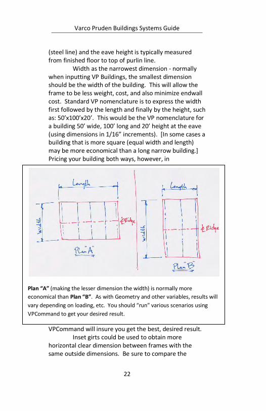
Width as the narrowest dimension - normally when inputting VP Buildings, the smallest dimension should be the width of the building. This will allow the frame to be less weight, cost, and also minimize endwall cost. Standard VP nomenclature is to express the width first followed by the length and finally by the height, such as: 50’x100’x20’. This would be the VP nomenclature for a building 50’ wide, 100’ long and 20’ height at the eave (using dimensions in 1/16” increments). [In some cases a building that is more square (equal width and length) may be more economical than a long narrow building.] Pricing your building both ways, however, in
VPCommand will insure you get the best, desired result. Inset girts could be used to obtain more
horizontal clear dimension between frames with the same outside dimensions. Be sure to compare the
Plan “A” (making the lesser dimension the width) is normally more
economical than Plan “B”. As with Geometry and other variables, results will
vary depending on loading, etc. You should “run” various scenarios using
VPCommand to get your desired result.
Varco Pruden Buildings Systems Guide
23
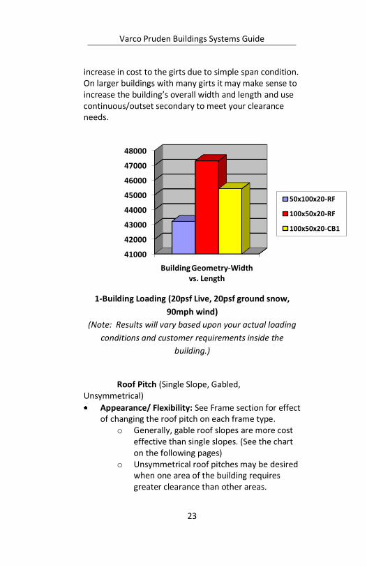
increase in cost to the girts due to simple span condition. On larger buildings with many girts it may make sense to increase the building’s overall width and length and use continuous/outset secondary to meet your clearance needs.
1-Building Loading (20psf Live, 20psf ground snow,
90mph wind)
(Note: Results will vary based upon your actual loading
conditions and customer requirements inside the
building.)
Roof Pitch (Single Slope, Gabled,
Unsymmetrical)
Appearance/ Flexibility: See Frame section for effect of changing the roof pitch on each frame type.
o Generally, gable roof slopes are more cost effective than single slopes. (See the chart on the following pages)
o Unsymmetrical roof pitches may be desired when one area of the building requires greater clearance than other areas.
41000
42000
43000
44000
45000
46000
47000
48000
Building Geometry-Width vs. Length
50x100x20-RF
100x50x20-RF
100x50x20-CB1
Varco Pruden Buildings Systems Guide
24
Site Drainage requirements: Verify with customer the direction(s) for the roof water drainage. A restriction in direction could dictate using a single slope roof vs. a gabled roof.
Roof Height Change or Floor Elevation
Change For sites that are not level, it may be more
economical to consider floor elevation changes or roof height changes to minimize column lengths.
Single Slope vs. Gable Slope Gable slope buildings are less expensive than single
slope buildings in many cases.
Gables are more economical when the building loads are heavier.
Gables typically offer larger savings in wider buildings than narrow buildings.
As always, building codes have some impact on this comparison.
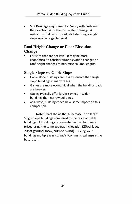
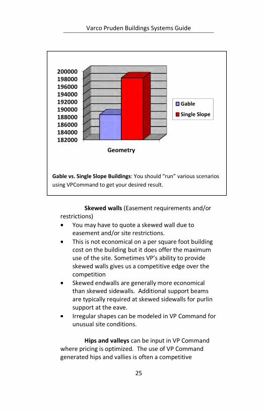
Note: Chart shows the % increase in dollars of
Single Slope buildings compared to the price of Gable buildings. All buildings represented in the chart were
priced using the same geographic location (20psf Live, 20psf ground snow, 90mph wind). Pricing your buildings multiple ways using VPCommand will insure the best result.
Varco Pruden Buildings Systems Guide
25
Skewed walls (Easement requirements and/or
restrictions)
You may have to quote a skewed wall due to easement and/or site restrictions.
This is not economical on a per square foot building cost on the building but it does offer the maximum use of the site. Sometimes VP’s ability to provide skewed walls gives us a competitive edge over the competition
Skewed endwalls are generally more economical than skewed sidewalls. Additional support beams are typically required at skewed sidewalls for purlin support at the eave.
Irregular shapes can be modeled in VP Command for unusual site conditions.
Hips and valleys can be input in VP Command
where pricing is optimized. The use of VP Command generated hips and vallies is often a competitive
Gable vs. Single Slope Buildings: You should “run” various scenarios
using VPCommand to get your desired result.
182000184000186000188000190000192000194000196000198000200000
Geometry
Gable
Single Slope
Varco Pruden Buildings Systems Guide
26
advantage over manual design and detailing of the structure.
Hips and Valleys are generally more economical if symmetrical (45º), rather than skewed.
The ability to utilize the pre-defined shapes in VP Command minimizes the input for the project. Custom shapes can be input as required.
Starting Eave Height for Clearances in VP
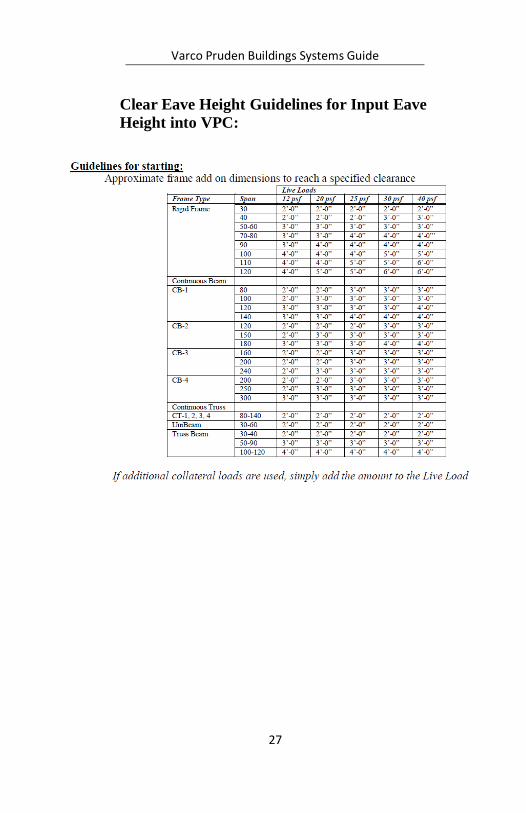
Command Many projects require a minimum or specified
clearance under the frame of the building. To get the dimension that is required is a “trial
and error” procedure. There are various ways to achieve the required frame clearance on a Building using VP Command. Use the following chart to determine an additional dimension to add to the required clear dimension to get a starting eave height dimension when inputting the job into VP Command. Once the job is run, review the clear dimension designed and make and adjustments as needed. Rerun the job until you are satisfied with the dimensions.
Another method is to specify the depth of the rafter that will yield the required clearance. This method will usually result in a non-competitive (pricewise) design if you restrict the depth less than the program chooses. Input the job and transfer the project for Interactive Frame Design (IA) assistance with a note in the “frames note” section describing what you want. The designer will attempt to design the frame for what is required and return the frame to you based on the starting eave height you have input.
Request assistance from your VP Service Team to help determine the correct eave height to satisfy the requirements.
Varco Pruden Buildings Systems Guide
27
Clear Eave Height Guidelines for Input Eave
Height into VPC:

Varco Pruden Buildings Systems Guide
28
Notes:

Varco Pruden Buildings Systems Guide
29
Notes:
Varco Pruden Buildings Systems Guide
30
Attachments What appearance options will be required for
the building? Questions for the Customer Appearance considerations for attachments
Piggyback canopy?
Built-up canopy?
Façade?
Parapet?
Soffit?
Rake extension? Optimization Concepts - Appearance
considerations
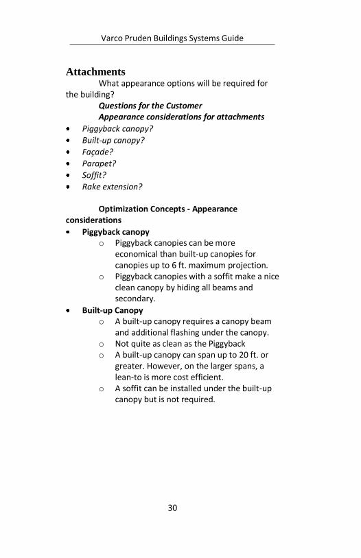
Piggyback canopy o Piggyback canopies can be more
economical than built-up canopies for canopies up to 6 ft. maximum projection.
o Piggyback canopies with a soffit make a nice clean canopy by hiding all beams and secondary.
Built-up Canopy o A built-up canopy requires a canopy beam
and additional flashing under the canopy. o Not quite as clean as the Piggyback o A built-up canopy can span up to 20 ft. or
greater. However, on the larger spans, a lean-to is more cost efficient.
o A soffit can be installed under the built-up canopy but is not required.
Varco Pruden Buildings Systems Guide
31
Piggyback canopies are appropriate for
cantilevers up to 6’ maximum projection while built-up beam canopies can extend to larger lengths. Both have advantages to be considered. For small overhangs the Piggy Back Canopy is a better choice than the beam canopy. Piggyback canopies combined with roof extensions are cleanly trimmed and sheeted to hide primary and secondary framing.
Rake or Roof extension A Rake Extension must be on an endwall.
A Rake extension can be cantilevered purlins or bolt on. Generally, a cantilevered rake extension can only span up to 6’. Spans beyond 6’ require a bolt on extension.
The outside edge of a rake extension does not have to be straight; they can be skewed, however, a skewed rake extension is more costly than a straight extension.
A rake extension can be used with or without a soffit. Only add a soffit if it is required.
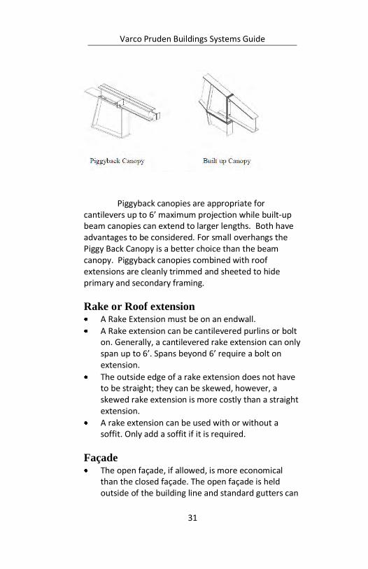
Façade The open façade, if allowed, is more economical
than the closed façade. The open façade is held outside of the building line and standard gutters can
Varco Pruden Buildings Systems Guide
32
be used. A closed facade requires multi-gutter and is considerably more expensive.
Endwall facades are normally closed facades, but can be open if required.
The sloped-mansard façade is generally the most expensive façade system and should be avoided when possible. It is more difficult and costly to erect.
Many times extending the sidewall above the roofline will serve the same function as a façade at a reduced cost. (See parapets)
When using the FSX façade a minimum projection of 2’-0” is required to keep the multi-gutter outside of the building line.
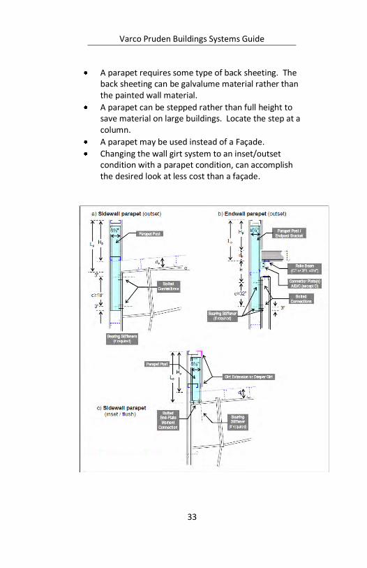
Parapet A parapet is a wall extension above the roofline.
Typically there is no break in the wall plane.
Varco Pruden Buildings Systems Guide
33
A parapet requires some type of back sheeting. The back sheeting can be galvalume material rather than the painted wall material.
A parapet can be stepped rather than full height to save material on large buildings. Locate the step at a column.
A parapet may be used instead of a Façade.
Changing the wall girt system to an inset/outset condition with a parapet condition, can accomplish the desired look at less cost than a façade.
Varco Pruden Buildings Systems Guide
34
Soffit Soffits are located below canopies, rake extensions,
facades, overhangs, and in building wall offset conditions.
Additional framing is required for the support of the soffit panels unless the soffit can be attached directly to the bottom of the purlins.
Many panels are available for use as soffits. o Panel Rib and Vee Rib are the most
economical panels.
Soffit in VPCommand is input within the Liner folder. VPCommand considers the panel on the back side of the main wall or roof as Liner.
If the majority of your canopies / rake extensions require soffit panel you should add these items to your VP Command “Default” files so that soffit will automatically be provided.

Varco Pruden Buildings Systems Guide
35
Notes:
Varco Pruden Buildings Systems Guide
36
Loading The building will have to be designed to meet
local codes and requirements, but are there any special requirements the customer will require? How does the loading impact the project?
Questions for the Customer Site location and topography for the building
(for code information)
Wind exposure on the site?
Collateral loads (examples)?
Ceiling Types (Acoustical, Plaster, etc.)?
Sprinkler Lines?
Lighting?
HVAC Ducts?
Will special deflection requirements need to be considered?
Optimization Concepts The answer to the questions allows the
opportunity to consider the various aspects that pertain to loading.
Codes Governing Building Code: It is important to be
knowledgeable about the governing code that applies to the project location.
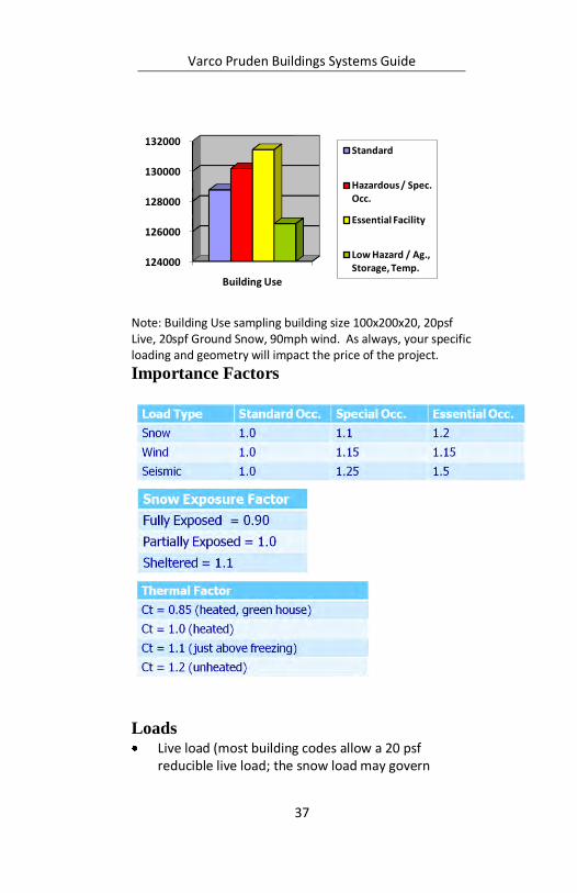
Building Use The building use can impact the loading factors for
the project
Essential facilities, hazard material storage or buildings intended for high occupancy etc., will require higher load factors.
Low hazard / agricultural buildings will decrease the cost.
Varco Pruden Buildings Systems Guide
37
Note: Building Use sampling building size 100x200x20, 20psf Live, 20spf Ground Snow, 90mph wind. As always, your specific loading and geometry will impact the price of the project.
Importance Factors
Loads Live load (most building codes allow a 20 psf
reducible live load; the snow load may govern
124000
126000
128000
130000
132000
Building Use
Standard
Hazardous / Spec. Occ.
Essential Facility
Low Hazard / Ag., Storage, Temp.

Varco Pruden Buildings Systems Guide
38
building design.) Some local codes require something higher.
The higher the load the higher the cost, the lower the load the lower the cost.
If the specified live load is higher than the governing code minimum, you need to question the reasons.
If the collateral loads are incorrectly included in the live load you need to separate them.
Use live load reduction whenever possible to potentially reduce the cost.
All codes allow reductions (except for a few
cities). Make sure you are using the loading requirements for the jobsite.
Collateral Load The charts related to collateral loads (shown
later in this section) were taken from the “help section” of VP Command and represent typical collateral loads. This is intended as a reference only.
Varco Pruden Buildings Systems Guide
39
When the collateral loading conditions on a portion of the building differs substantially from the base collateral building load, then an area representing the difference should be input into VP Command to optimize the design. For example, a project has 5 pounds per square foot (psf) collateral load with a specific area containing 8 psf collateral load –define the area (as a special load) and add the 3 lbs - difference to equal 8. Location of the specified area for the collateral load near a frame line or interior column lowers the impact over loads placed in the center of the bay.
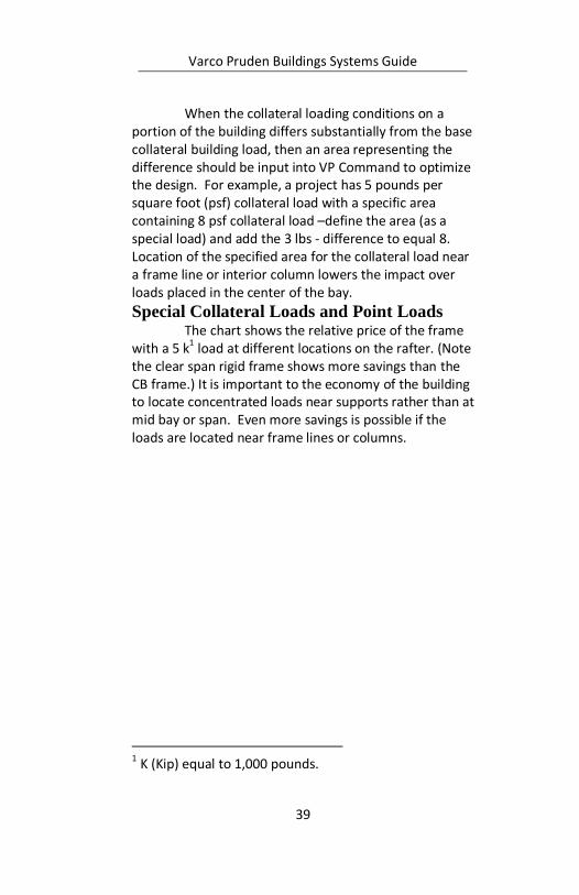
Special Collateral Loads and Point Loads The chart shows the relative price of the frame
with a 5 k1 load at different locations on the rafter. (Note
the clear span rigid frame shows more savings than the CB frame.) It is important to the economy of the building to locate concentrated loads near supports rather than at mid bay or span. Even more savings is possible if the loads are located near frame lines or columns.
1 K (Kip) equal to 1,000 pounds.

Varco Pruden Buildings Systems Guide
40
Note: Examples of special collateral loads include, sprinkler, line loads, cable trays, and catwalks. Examples of Point Loads include mechanical units, basketball goals, and scoreboards.
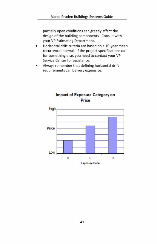
Wind Load Exposure “B” is defined as Urban and suburban
areas, wooded areas, or other terrain with numerous closely spaced obstructions having the size of single-family dwellings or larger.
Exposure “C” is defined as Open terrain with scattered obstructions having heights generally less than 30 ft.
Exposure “D” is defined as flat, unobstructed areas exposed to wind flowing over open water (excluding shore-lines in hurricane prone regions) for a distance of at least 1 mile.
Exposure “C” (open terrain) is more severe than exposure “B”.
Wind Exposure “B” generates the most cost effective designs and is acceptable for most areas of construction. Verify with your building code officials who will many times state what the exposure is for a particular job site.
Buildings which have open walls or partially open walls must be designed accordingly. Open and
Varco Pruden Buildings Systems Guide
41
partially open conditions can greatly affect the design of the building components. Consult with your VP Estimating Department.
Horizontal drift criteria are based on a 10-year mean recurrence interval. If the project specifications call for something else, you need to contact your VP Service Center for assistance.
Always remember that defining horizontal drift requirements can be very expensive.
Varco Pruden Buildings Systems Guide
42
Dead loads Other roof construction impacts the dead load
Built up deck, roof by others, rubber roof, or specific dead load included in the building specs.
The weight of the mezzanine structure and floor system is considered dead loads.
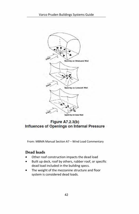
From: MBMA Manual Section A7 – Wind Load Commentary
Varco Pruden Buildings Systems Guide
43
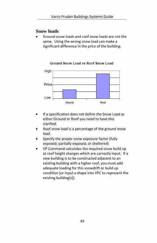
Snow loads Ground snow loads and roof snow loads are not the
same. Using the wrong snow load can make a significant difference in the price of the building.
If a specification does not define the Snow Load as either Ground or Roof you need to have this clarified.
Roof snow load is a percentage of the ground snow load.
Specify the proper snow exposure factor (fully exposed; partially exposed; or sheltered)
VP Command calculates the required snow build up at roof height changes which are correctly input. If a new building is to be constructed adjacent to an existing building with a higher roof, you must add adequate loading for this snowdrift or build up condition [or input a shape into VPC to represent the existing building(s)].

Varco Pruden Buildings Systems Guide
44
Note: Charts are for reference only. Your specific loading and building geometry will impact final results.
41000
42000
43000
44000
45000
46000
47000
Open Snow Exposure
40 psf GS (25.2 psf roof)
40 psf roof (63.49 psf GS)
40 psf both
43500
44000
44500
45000
45500
46000
46500
Sheltered Snow Exposure
40 psf GS (33.6 psf roof)
40 psf roof (47.62 psf GS)
40 psf both
Varco Pruden Buildings Systems Guide
45
Seismic Loads Accurately input the seismic zone. Ss; S1; and Soil
Profile.
The additional weight of masonry and tilt walls supported by our structure adversely affects the cost of the structure in higher seismic zones.
For larger projects with high seismic loads contact your VP Service center for additional bracing options.
If the project has concrete or masonry walls contact your VP service center to discuss the possibility of using those walls as shear walls to reduce bracing cost.
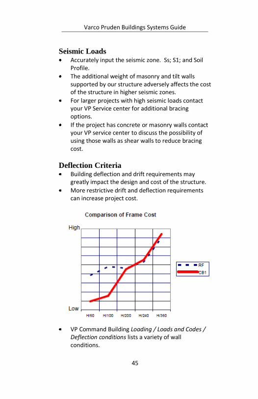
Deflection Criteria Building deflection and drift requirements may
greatly impact the design and cost of the structure.
More restrictive drift and deflection requirements can increase project cost.
VP Command Building Loading / Loads and Codes / Deflection conditions lists a variety of wall conditions.
Varco Pruden Buildings Systems Guide
46
Question specs that are stricter than code
Contact your VP support person for assistance.
Look at partial walls impact.
Lateral Deflection
Definitions and Background There are two types of lateral deflection limits:
Building drift and In-span deflection of a vertical wall. The following are definitions that are often used
with lateral deflection limits:
Bare Frame Deflection. Typical building drift or frame sidesway criteria expresses lateral movement in terms of "bare frame" deflection. Bare frame deflection considers the stiffness of the frame alone without any help from the roof or wall diaphragm or column base fixety in most cases.
Actual lateral deflections of completed buildings are less than theoretical calculations for "bare frames". The MBMA Building Systems Manual goes into great detail on this subject in Section C5.6 and Appendix A6. The MBMA Manual and the AISC's Design Guide #3 "Serviceability Design Considerations for Low Rise Buildings" both recommend using a 10-year mean
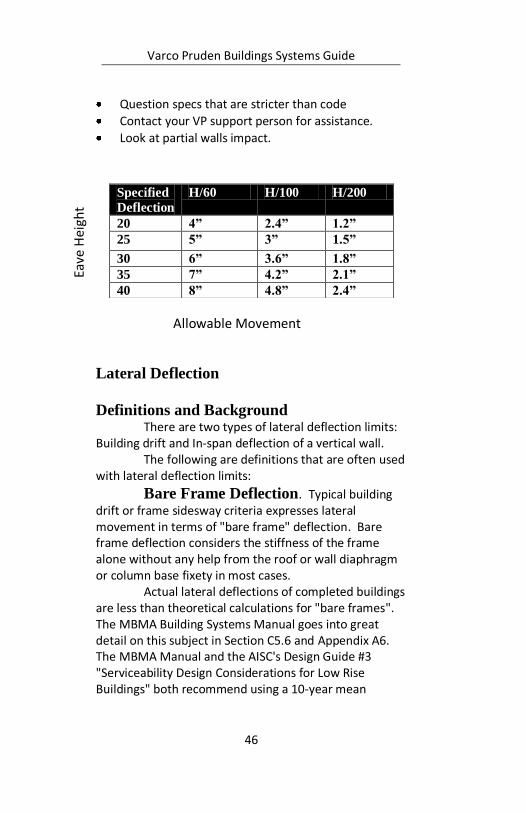
Specified
Deflection
H/60 H/100 H/200
20 4” 2.4” 1.2”
25 5” 3” 1.5”
30 6” 3.6” 1.8”
35 7” 4.2” 2.1”
40 8” 4.8” 2.4”
Eave
Hei
ght
Allowable Movement
Varco Pruden Buildings Systems Guide
47
recurrence wind pressure instead of 50-year when calculating lateral deflections.
Ten-Year Wind: A 10-year wind pressure can be approximated by 75% of the 50-year wind pressure. AISC's Serviceability paper explains the philosophy behind the 10-year wind: "Ten year recurrence interval winds are recommended due to the non-catastrophic nature of serviceability issues and the need to provide a standard consistent with day-to-day behavior and average perceptions. Fifty-year winds are special events."
Frame Load Sharing: Frame load sharing is an economical design method to reduce the effects of concentrated lateral loads (lateral crane loads) applied on one frame. A lateral force applied to one frame may be distributed to the frames on either side by roof rod bracing or some other physical means. Frame load sharing does not apply to lateral wind or seismic loads. Further discussion of frame load sharing will be addressed in the later section on Crane Buildings.

Varco Pruden Buildings Systems Guide
48
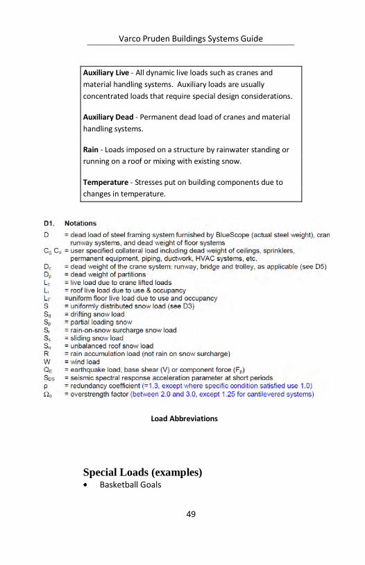
Load Definition Summary Dead - Permanent load due to the weight of the metal building
system itself including the roof panels, insulation, purlins, and
primary frames.
Collateral - Additional dead loads, other than the weight of the
building system itself, such as sprinklers, mechanical and
electrical systems and ceilings. Collateral loads may be either
uniformly distributed or concentrated loads and may not
always be located in the same place during the lifetime of the
structure.
Roof Live - Temporarily applied roof loads, typically (but not
always) erection load or an unspecified minimum live load as
required by the governing building code. This would be a
uniform load over the entire roof area.
Alternate Span Live - Temporarily applied roof loads to
adjacent or alternate spans of a continuous beam (i.e. rafter
loading between interior columns). This type of loading
condition could occur during erection of a building.
Snow - The load induced by the weight of snow on the
structure. Unbalanced Snow- Removing one slope live load of a
gable roof, and leaving load on the other side.
Wind - The pressure and suctions on wall and roof areas caused
by wind velocities acting in any direction.
Seismic - The horizontal and vertical force acting on a structural
system due to the action of an earthquake.
Floor Live - Temporarily applied loads on a floor such as people,
furniture, machines, etc.
Floor Dead - Permanent loads due to the weight of the
structure including framing, decking and flooring materials.
Varco Pruden Buildings Systems Guide
49
Auxiliary Live - All dynamic live loads such as cranes and
material handling systems. Auxiliary loads are usually
concentrated loads that require special design considerations.
Auxiliary Dead - Permanent dead load of cranes and material
handling systems.
Rain - Loads imposed on a structure by rainwater standing or
running on a roof or mixing with existing snow.
Temperature - Stresses put on building components due to
changes in temperature.
Special Loads (examples) Basketball Goals
Load Abbreviations
Varco Pruden Buildings Systems Guide
50
Fall Protection
HVAC Equipment Location
Cranes / Monorails
Cable Trays
Future use for the building structure
Future Additions (Lean-to’s, additional bays, etc.)
Future Loading Changes
Site location for the building (for code
information) Exposure on the site (see Wind and Snow sections)
Possible impact from snow drift load from adjacent structures
Collateral loads (examples) Ceiling Types (Acoustical, Plaster, etc.)
Sprinklers Lines
Lighting
HVAC Duct
Special deflection requirements need to be
considered Horizontal and vertical deflection criteria greatly
impact the building cost.
See serviceability chart for recommendations
Varco Pruden Buildings Systems Guide
51
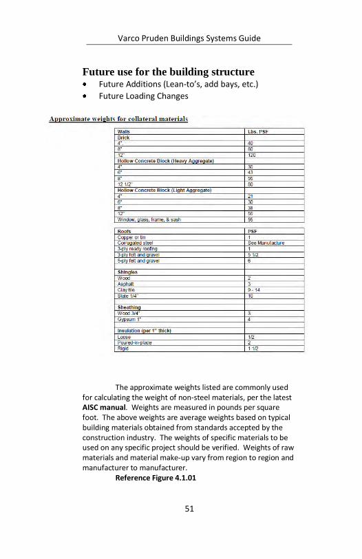
Future use for the building structure Future Additions (Lean-to’s, add bays, etc.)
Future Loading Changes
The approximate weights listed are commonly used
for calculating the weight of non-steel materials, per the latest AISC manual. Weights are measured in pounds per square foot. The above weights are average weights based on typical building materials obtained from standards accepted by the construction industry. The weights of specific materials to be used on any specific project should be verified. Weights of raw materials and material make-up vary from region to region and manufacturer to manufacturer.
Reference Figure 4.1.01
Varco Pruden Buildings Systems Guide
52
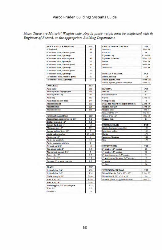
Additional Weights for use from Reference Material in VP Command
The above weights are average material weights
only based on typical building materials obtained from standards accepted by the construction industry. The weights of specific materials to be used on any specific project should be verified based on the actual materials to be used.
Actual “in-place weights” should be confirmed with the Engineer of Record, or the appropriate building code official.
Varco Pruden Buildings Systems Guide
53
Varco Pruden Buildings Systems Guide
54
Strength and Serviceability Building codes and specifications require that
every building be designed to satisfy two fundamental criteria – strength and serviceability.
Strength The building must be designed with adequate
strength to resist all environmental and user-imposed loads without structural failure. Structural failure is generally defined as a condition in which one or more of the structural elements of the building lose their ability to resist the forces that they are required to carry in order to maintain the integrity of the building. Structural failures often result in significant problems ranging from roof leaks to total collapse and can pose a threat to property and life.
Serviceability Each structural system within the building must
be designed to provide appropriate serviceability. This means that the structural systems must be able to perform their intended functions without interfering with the buildings operations. For example, a floor system must be designed with the appropriate amount of stiffness. In some cases, when the designer has failed to adequately consider this issue, floor vibrations have been so perceptible that building occupants have refused to work in the building.
In most cases serviceability problems don’t represent any immediate danger of structural failure. However, serviceability problems have the potential to significantly reduce a building’s usefulness. Therefore, serviceability considerations are often equally as important in the design of a building as its strength.
The AISC's Design Guide #3 "Serviceability Design Considerations for Low Rise Buildings" describes the difference between the two limit states and gives some guidelines.

Varco Pruden Buildings Systems Guide
55
The serviceability limits on the following pages
are recommended guidelines for the design of building components and are based on the AISC's Design Guide #3 "Serviceability Design Considerations for Low Rise Buildings." These values may be overridden by any specifications, applicable local building code criteria, or owner's choice. The criteria set in this document provide recommendations for customer consideration.
Most buildings are required to have an “Engineer of Record” who assumes the responsibility for the building. She is registered to practice engineering in the building location and is responsible for sealing the building documents for the governing municipality. Normally she will specify with the owner’s consent the serviceability requirements for the building. When she does not, the only governing measure for design is the governing codes and good engineering practice.
Varco Pruden Buildings Systems Guide
56
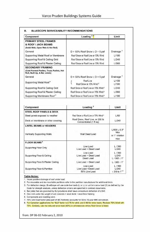
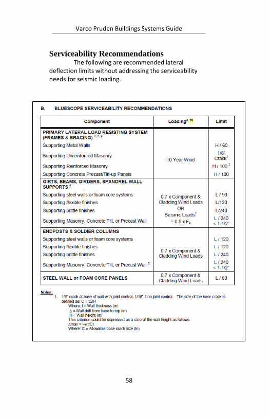
Serviceability Recommendations
from: DP 06-02 February 2, 2010
Varco Pruden Buildings Systems Guide
57
Component Loading Limit 1,3 Notes:
Deflection limits are based on information obtained from AISC's Design Guide #3 "Serviceability Design Considerations For Low Rise Buildings,"1990.
Insure positive drainage of roof under load.
Refer to applicable Building Code for other deflection limits.
For moveable and de-mountable partitions refer to manufacturer for additional limits.
Recommended minimum roof slope of ¼: 12 for Standing Seam roofs and ½: 12 for exposed fastener roofs.
Varco Pruden Buildings Systems Guide
58
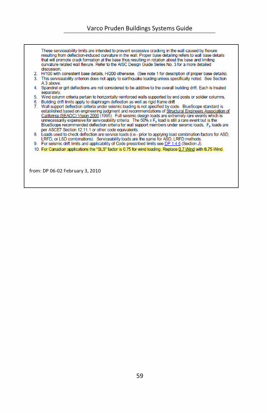
Serviceability Recommendations The following are recommended lateral
deflection limits without addressing the serviceability needs for seismic loading.
Varco Pruden Buildings Systems Guide
59
from: DP 06-02 February 3, 2010
Varco Pruden Buildings Systems Guide
60
Notes:
Varco Pruden Buildings Systems Guide
61
Notes:

Varco Pruden Buildings Systems Guide
62
Notes:

Varco Pruden Buildings Systems Guide
63
Notes:
Varco Pruden Buildings Systems Guide
64
Frames The answers to the questions in this section are
vital to the economy of the building. The decisions on framing will greatly affect the project price.
Questions for the Customer
Can we use the most economical framing system and bay spacing?
Are there any clearance requirements (horizontal and vertical)?
Can we use the most economical interior column spacing and configuration (pipe, tube, three-plate)?
Are there any restrictions or preferences that would control the selection of Solid Web over Open Web framing? (lighting, mechanical equipment distribution, inside clearances.)
Are there special access requirements for the building (entry, loading dock , specialty doors)?
Can we use the most economical frame design for the roof pitch?
Do you have any limitations/restrictions for the exterior columns (configuration, depth, tapered, straight, supermarket, etc.)?
Can columns be flange braced to walls not by VP?
Are the wall systems load-bearing?
Identify column base conditions and elevations?
Do you expect future expansions to affect the endwall and sidewall design?
Frame Optimization Concepts General Bay Spacing: Optimize the bay spacing for the
length of the building. Bay space economy is clearly defined by the best overall building price. In some cases the bay spacing may favor one parameter for the frame spacing and another for the girt and purlin spacing. When you look at the overall building you can design for
Varco Pruden Buildings Systems Guide
65
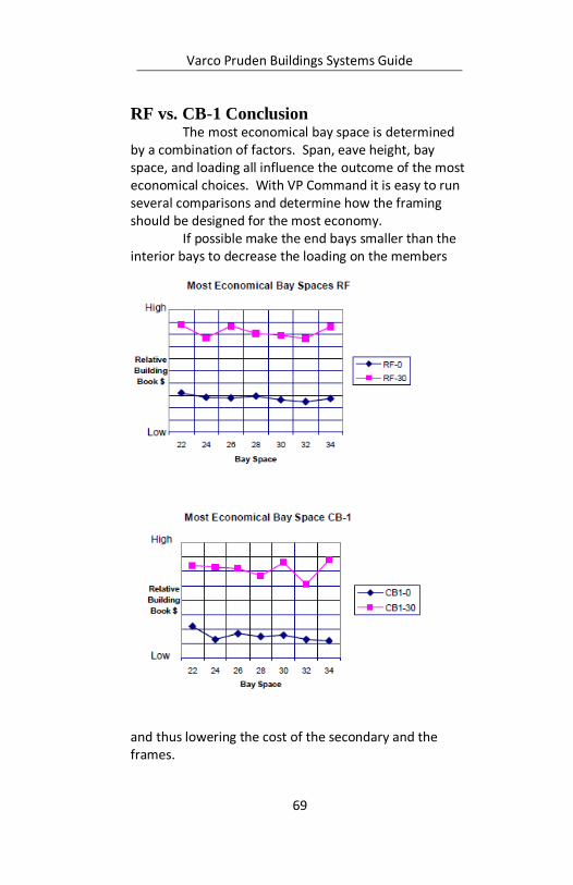
the overall maximum economy. These charts look at the total building price. They show comparisons for a building 100’x216’x20’. The RF-0 and CB1-0 is for a Ground Snow Load = 0 and the RF-30 and CB1-30 for a Ground Snow Load = 30 psf.
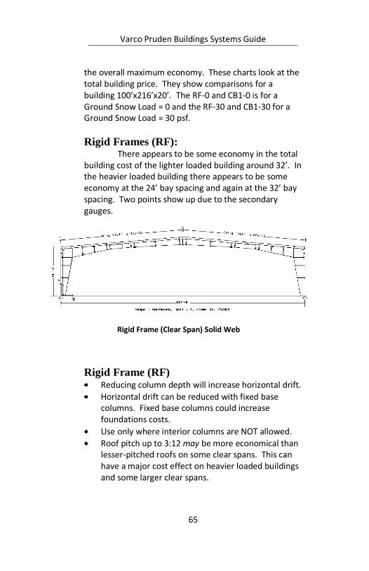
Rigid Frames (RF): There appears to be some economy in the total
building cost of the lighter loaded building around 32’. In the heavier loaded building there appears to be some economy at the 24’ bay spacing and again at the 32’ bay spacing. Two points show up due to the secondary gauges.
Rigid Frame (RF) Reducing column depth will increase horizontal drift.
Horizontal drift can be reduced with fixed base columns. Fixed base columns could increase foundations costs.
Use only where interior columns are NOT allowed.
Roof pitch up to 3:12 may be more economical than lesser-pitched roofs on some clear spans. This can have a major cost effect on heavier loaded buildings and some larger clear spans.
Rigid Frame (Clear Span) Solid Web
Varco Pruden Buildings Systems Guide
66
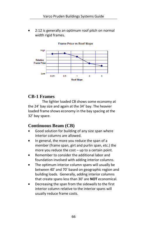
2:12 is generally an optimum roof pitch on normal width rigid frames.
CB-1 Frames The lighter loaded CB shows some economy at
the 24’ bay size and again at the 34’ bay. The heavier loaded frame shows economy in the bay spacing at the 32’ bay space.
Continuous Beam (CB) Good solution for building of any size span where
interior columns are allowed.
In general, the more you reduce the span of a member (frame span, girt and purlin span, etc.) the more you reduce the cost – up to a certain point.
Remember to consider the additional labor and foundation involved with adding interior columns.
The optimum interior column spans will usually be between 40’ and 70’ based on geographic region and building loads. Generally, adding interior columns that create spans less than 30’ are NOT economical.
Decreasing the span from the sidewalls to the first interior column relative to the interior spans will usually reduce frame costs.
Varco Pruden Buildings Systems Guide
67
Optional interior tube column may be the most economical on interior column lengths exceeding 35 feet.
Eliminating exterior columns when there are load bearing masonry walls can be an economical option with CB frames.
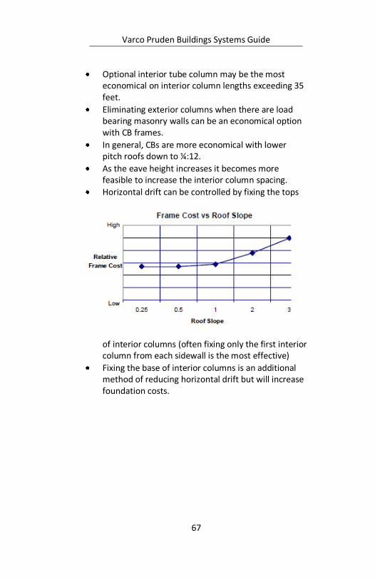
In general, CBs are more economical with lower pitch roofs down to ¼:12.
As the eave height increases it becomes more feasible to increase the interior column spacing.
Horizontal drift can be controlled by fixing the tops
of interior columns (often fixing only the first interior column from each sidewall is the most effective)
Fixing the base of interior columns is an additional method of reducing horizontal drift but will increase foundation costs.
Varco Pruden Buildings Systems Guide
68
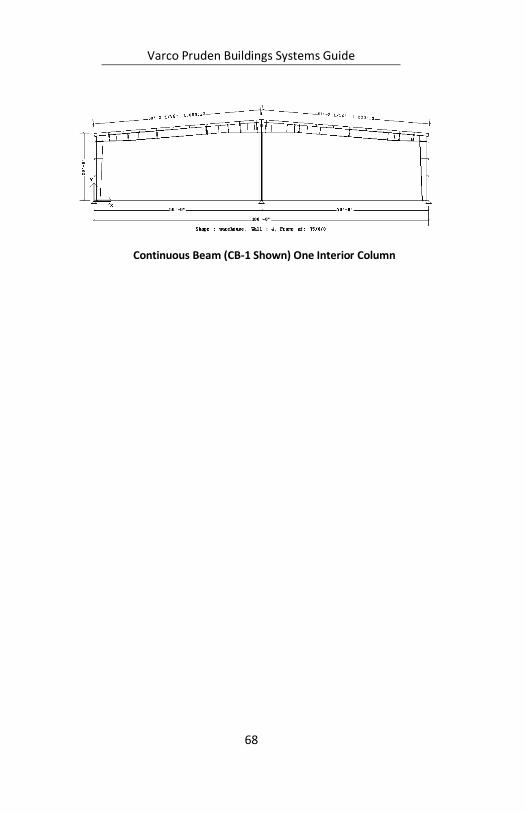
Continuous Beam (CB-1 Shown) One Interior Column
Varco Pruden Buildings Systems Guide
69
RF vs. CB-1 Conclusion The most economical bay space is determined
by a combination of factors. Span, eave height, bay space, and loading all influence the outcome of the most economical choices. With VP Command it is easy to run several comparisons and determine how the framing should be designed for the most economy.
If possible make the end bays smaller than the interior bays to decrease the loading on the members
and thus lowering the cost of the secondary and the frames.
Varco Pruden Buildings Systems Guide
70
Frame Span Try to span the frames the shortest dimension
of the building to reduce cost. See Basic Geometry section.
Frames and Roof Slope Generally buildings with symmetrical gabled
roofs are less expensive than those using single slope.
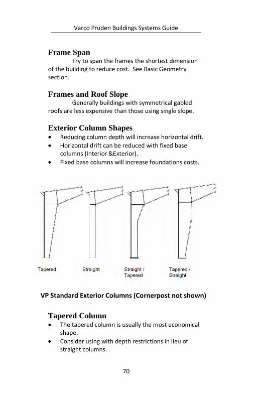
Exterior Column Shapes Reducing column depth will increase horizontal drift.
Horizontal drift can be reduced with fixed base columns (Interior &Exterior).
Fixed base columns will increase foundations costs.
Tapered Column The tapered column is usually the most economical
shape.
Consider using with depth restrictions in lieu of straight columns.
VP Standard Exterior Columns (Cornerpost not shown)
Varco Pruden Buildings Systems Guide
71
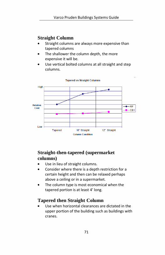
Straight Column Straight columns are always more expensive than
tapered columns
The shallower the column depth, the more expensive it will be.
Use vertical bolted columns at all straight and step columns.
Straight-then-tapered (supermarket
columns) Use in lieu of straight columns.
Consider where there is a depth restriction for a certain height and then can be relaxed perhaps above a ceiling or in a supermarket.
The column type is most economical when the tapered portion is at least 4’ long.
Tapered then Straight Column Use when horizontal clearances are dictated in the
upper portion of the building such as buildings with cranes.
Varco Pruden Buildings Systems Guide
72
Other Frame Types
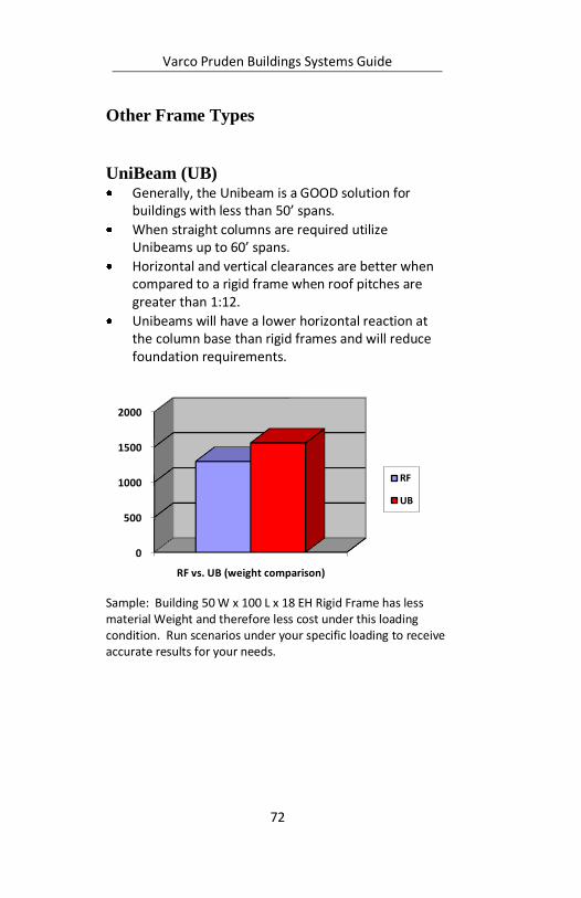
UniBeam (UB) Generally, the Unibeam is a GOOD solution for
buildings with less than 50’ spans.
When straight columns are required utilize Unibeams up to 60’ spans.
Horizontal and vertical clearances are better when compared to a rigid frame when roof pitches are greater than 1:12.
Unibeams will have a lower horizontal reaction at the column base than rigid frames and will reduce foundation requirements.
Sample: Building 50 W x 100 L x 18 EH Rigid Frame has less material Weight and therefore less cost under this loading condition. Run scenarios under your specific loading to receive accurate results for your needs.
0
500
1000
1500
2000
RF vs. UB (weight comparison)
RF
UB
Varco Pruden Buildings Systems Guide
73
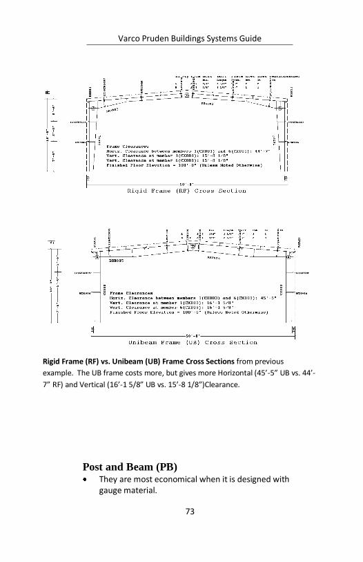
Post and Beam (PB) They are most economical when it is designed with
gauge material.
Rigid Frame (RF) vs. Unibeam (UB) Frame Cross Sections from previous
example. The UB frame costs more, but gives more Horizontal (45’-5” UB vs. 44’-
7” RF) and Vertical (16’-1 5/8” UB vs. 15’-8 1/8”)Clearance.
Varco Pruden Buildings Systems Guide
74
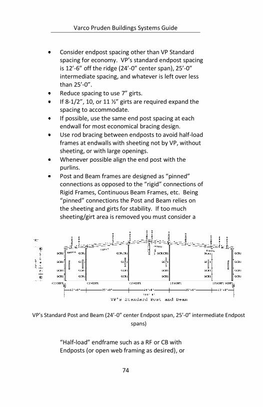
Consider endpost spacing other than VP Standard spacing for economy. VP’s standard endpost spacing is 12’-6” off the ridge (24’-0” center span), 25’-0” intermediate spacing, and whatever is left over less than 25’-0”.
Reduce spacing to use 7” girts.
If 8-1/2”, 10, or 11 ½” girts are required expand the spacing to accommodate.
If possible, use the same end post spacing at each endwall for most economical bracing design.
Use rod bracing between endposts to avoid half-load frames at endwalls with sheeting not by VP, without sheeting, or with large openings.
Whenever possible align the end post with the purlins.
Post and Beam frames are designed as “pinned” connections as opposed to the “rigid” connections of Rigid Frames, Continuous Beam Frames, etc. Being “pinned” connections the Post and Beam relies on the sheeting and girts for stability. If too much sheeting/girt area is removed you must consider a
“Half-load” endframe such as a RF or CB with Endposts (or open web framing as desired), or
VP’s Standard Post and Beam (24’-0” center Endpost span, 25’-0” intermediate Endpost
spans)
Varco Pruden Buildings Systems Guide
75
bracing between endposts. Consult with VP engineering for assistance.
For Future Expansion you may use any frame except a Post and Beam.
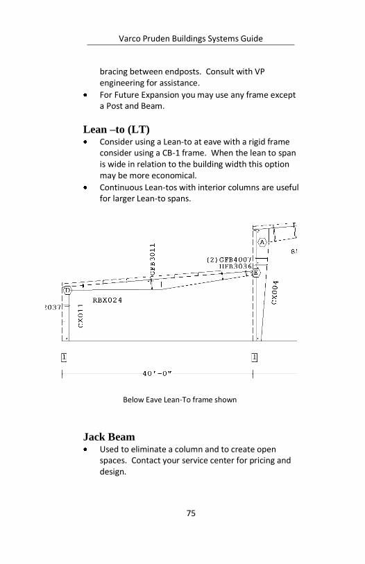
Lean –to (LT) Consider using a Lean-to at eave with a rigid frame
consider using a CB-1 frame. When the lean to span is wide in relation to the building width this option may be more economical.
Continuous Lean-tos with interior columns are useful for larger Lean-to spans.
Jack Beam Used to eliminate a column and to create open
spaces. Contact your service center for pricing and design.
Below Eave Lean-To frame shown
Varco Pruden Buildings Systems Guide
76
Interior Jack Beams allow the use of purlins rather than bar joist. This also permits the use of Panel Rib roof covering where bar joist would require SSR covering.
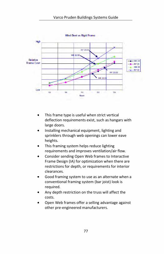
Open Web Frames (Wind Bents and Truss
Frames) Excellent frame choice for large clear spans (such as
arenas, hangars, sporting complexes, etc.) and heavy loadings.
Open Web frames couple the span economy with other benefits of the frame type, which allow for better lighting distribution and mechanical equipment distribution and the frame type is a clear choice.
This chart was developed for Wind Bents and Rigid Frames for spans of 125’, 150’, 175’, 200’, 225’ foot spans starting on the left and going to the right of the chart. The 20/30 lines were for 20 psf LL and 30 psf snow load (SL). The 20/20 are for 20 psf LL and 20 psf SL. The bays are all 25’ and the roof pitch was 1:12. It appears the Wind Bent becomes more economical in the 125’ to 150’ span area for these conditions. For other conditions, the optimum span may vary with roof pitch, loads and other conditions.
Varco Pruden Buildings Systems Guide
77
This frame type is useful when strict vertical deflection requirements exist, such as hangars with large doors.
Installing mechanical equipment, lighting and sprinklers through web openings can lower eave heights.
This framing system helps reduce lighting requirements and improves ventilation/air flow.
Consider sending Open Web frames to Interactive Frame Design (IA) for optimization when there are restrictions for depth, or requirements for interior clearances.
Good framing system to use as an alternate when a conventional framing system (bar joist) look is required.
Any depth restriction on the truss will affect the costs.
Open Web frames offer a selling advantage against other pre-engineered manufacturers.
Varco Pruden Buildings Systems Guide
78
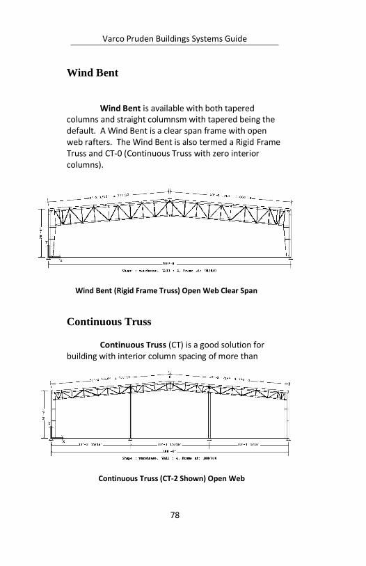
Wind Bent
Wind Bent is available with both tapered columns and straight columnsm with tapered being the default. A Wind Bent is a clear span frame with open web rafters. The Wind Bent is also termed a Rigid Frame Truss and CT-0 (Continuous Truss with zero interior columns).
Continuous Truss Continuous Truss (CT) is a good solution for
building with interior column spacing of more than
Wind Bent (Rigid Frame Truss) Open Web Clear Span
Continuous Truss (CT-2 Shown) Open Web
Varco Pruden Buildings Systems Guide
79
60’and heavy loading. In CT frames decreasing the span from the sidewalls to the first interior column relative to the interior spans will usually reduce frame costs. CTs are available with both tapered columns and straight columns with tapered being the default.
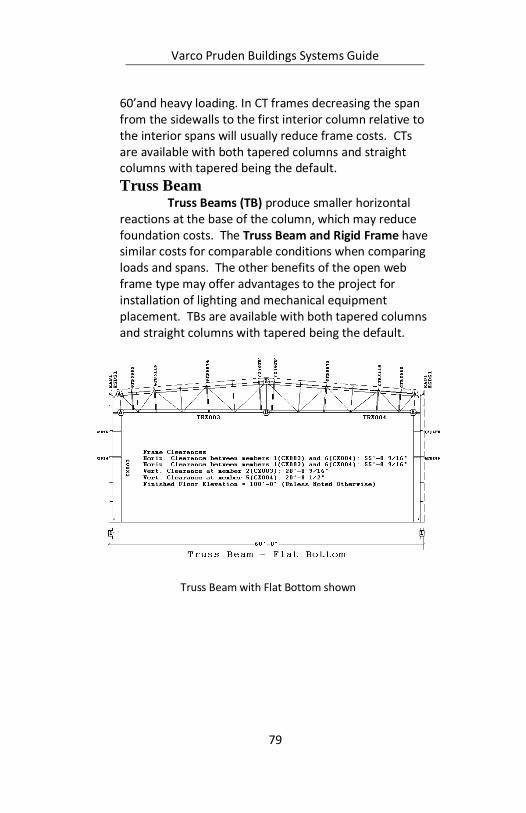
Truss Beam Truss Beams (TB) produce smaller horizontal
reactions at the base of the column, which may reduce foundation costs. The Truss Beam and Rigid Frame have similar costs for comparable conditions when comparing loads and spans. The other benefits of the open web frame type may offer advantages to the project for installation of lighting and mechanical equipment placement. TBs are available with both tapered columns and straight columns with tapered being the default.
Truss Beam with Flat Bottom shown
Varco Pruden Buildings Systems Guide
80
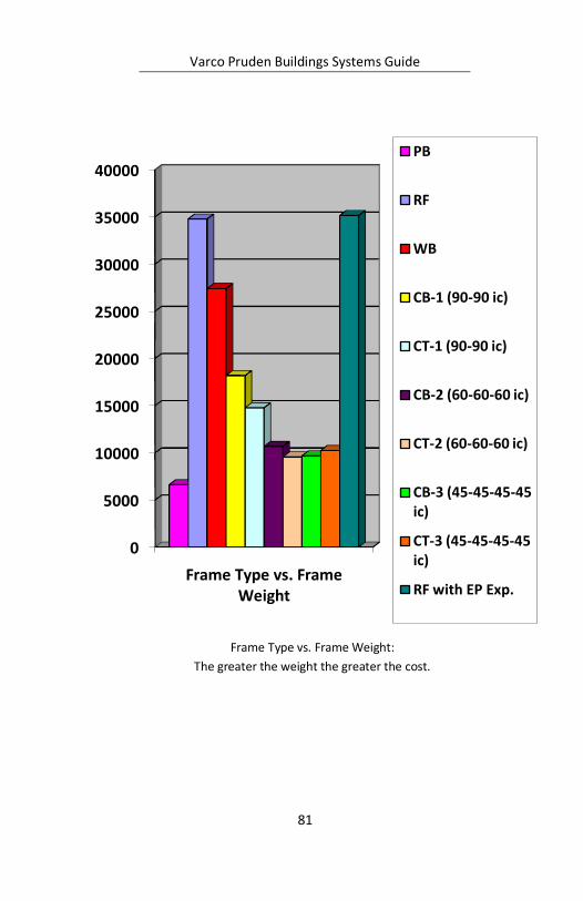
Frame Cost Comparisons:
The below frame comparisons are based on a building geometry of 180 W x 400 L x 20 EH; 30 psf GS, 90 mph Wind, 20 psf Live.
The more steel, the higher the cost - Open Web framing is more economical than Solid Web the larger the tributary area and the heavier the loads. As Interior Columns are added, the tributary is reduced, thus the difference in price between open and solid lessens until the trend is reversed and Solid Web becomes less expensive.
If you are uncertain what frame type to use or interior column is best with continuous beam and continuous truss frames, you can input a building into VP Command, locate various frame types throughout your shape (I used PB, RF, WB, CB-1, CT-1, CB-2, CT-2, CB-3, CT-3, RF w/EP). In my example the CT-2 with Interior Column spacing at 60-60-60 might be desired for it econimical value, ease of erectibility, and open web benefits (placing ducts, wiring, etc. in ewb area).
Remember that results vill vary depending upon your actual geometry and loading conditions.
Varco Pruden Buildings Systems Guide
81
Frame Type vs. Frame Weight:
The greater the weight the greater the cost.
0
5000
10000
15000
20000
25000
30000
35000
40000
Frame Type vs. Frame Weight
PB
RF
WB
CB-1 (90-90 ic)
CT-1 (90-90 ic)
CB-2 (60-60-60 ic)
CT-2 (60-60-60 ic)
CB-3 (45-45-45-45 ic)
CT-3 (45-45-45-45 ic)
RF with EP Exp.
Varco Pruden Buildings Systems Guide
82
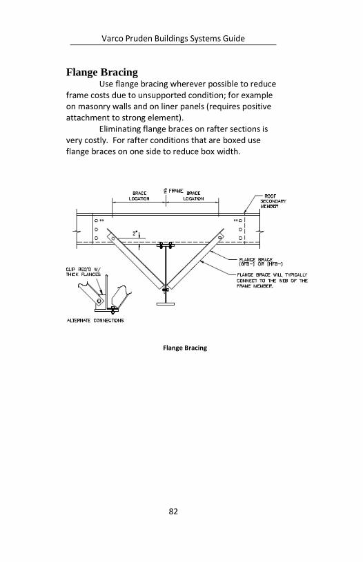
Flange Bracing Use flange bracing wherever possible to reduce
frame costs due to unsupported condition; for example on masonry walls and on liner panels (requires positive attachment to strong element).
Eliminating flange braces on rafter sections is very costly. For rafter conditions that are boxed use flange braces on one side to reduce box width.
Flange Bracing
Varco Pruden Buildings Systems Guide
83
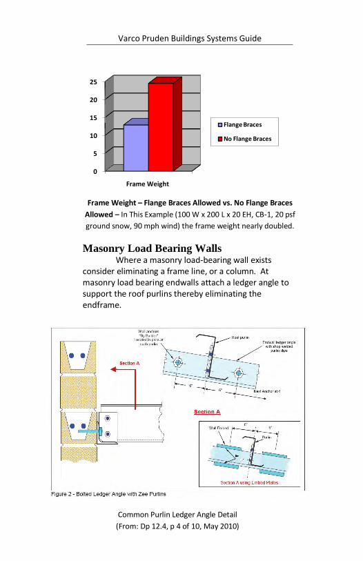
Frame Weight – Flange Braces Allowed vs. No Flange Braces
Allowed – In This Example (100 W x 200 L x 20 EH, CB-1, 20 psf
ground snow, 90 mph wind) the frame weight nearly doubled.
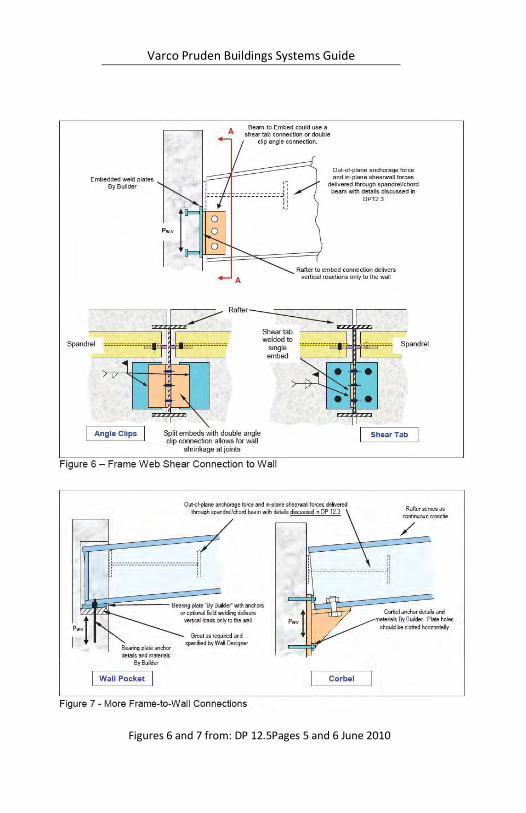
Masonry Load Bearing Walls Where a masonry load-bearing wall exists
consider eliminating a frame line, or a column. At masonry load bearing endwalls attach a ledger angle to support the roof purlins thereby eliminating the endframe.
0
5
10
15
20
25
Frame Weight
Flange Braces
No Flange Braces
Common Purlin Ledger Angle Detail
(From: Dp 12.4, p 4 of 10, May 2010)
Varco Pruden Buildings Systems Guide
84
Figures 6 and 7 from: DP 12.5Pages 5 and 6 June 2010

Varco Pruden Buildings Systems Guide
85
Notes:

Varco Pruden Buildings Systems Guide
86
Notes:
Varco Pruden Buildings Systems Guide
87
Cranes When cranes are involved in the project, get as
much information about the equipment as possible, including the intended use of the cranes.
Questions for the Customer
Will this building have any crane(s) now or in the future?
If there are multiple cranes will they be operating in the same bay at the same time?
Has the crane(s) manufacturer been determined? If so, is the crane data information sheet available? If not, whom should I contact for detailed crane information?
Who supplies crane accessories & support members (beams, stops, rails etc…)?
What is the crane layout and traveling direction?
Can we use bracing between the interior columns (are there any work flow concerns that would prevent interior bracing)?
Crane Optimization Concepts Make sure you know the classification of the crane
(A,B,C,D,E,F – See Crane Service Classifications at the end of this section.)
Know as much as you can about wheel loadings, bridge weight, trolley weight, crane operations, type, clearances, etc. in order to get the best price on the buildings. (See order clarification form) or crane data sheet from supplier.
Different classifications of cranes dictate the deflection and drift on the building and crane girder system. If a higher classification is used than is required, the price of the building will be impacted.
Remote controls have the same impact on the building as cab operated. Use pendant controls in lieu of remote controls if possible.

Varco Pruden Buildings Systems Guide
88
All buildings with class E or F should be priced by the VP Buildings’ Estimating Group.
Position the crane with the bridge spanning the width of the building rather than the length for best cost.
In most cases, smaller bay spacing will be more economical.
Smaller cranes can be supported on brackets, larger cranes require independent crane columns or step columns or hybrid-laced columns. Contact your Service Center for additional information.
Underhung cranes are supported by the rafter. Top running cranes are supported on brackets or columns. Generally top running crane systems are less expensive than underhung crane systems.
Common Crane to Column Connection
Varco Pruden Buildings Systems Guide
89
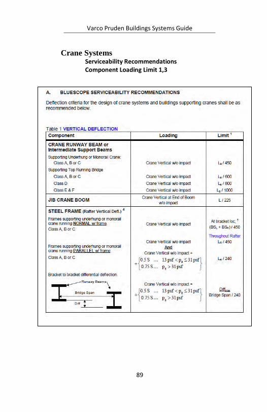
Crane Systems Serviceability Recommendations Component Loading Limit 1,3
Varco Pruden Buildings Systems Guide
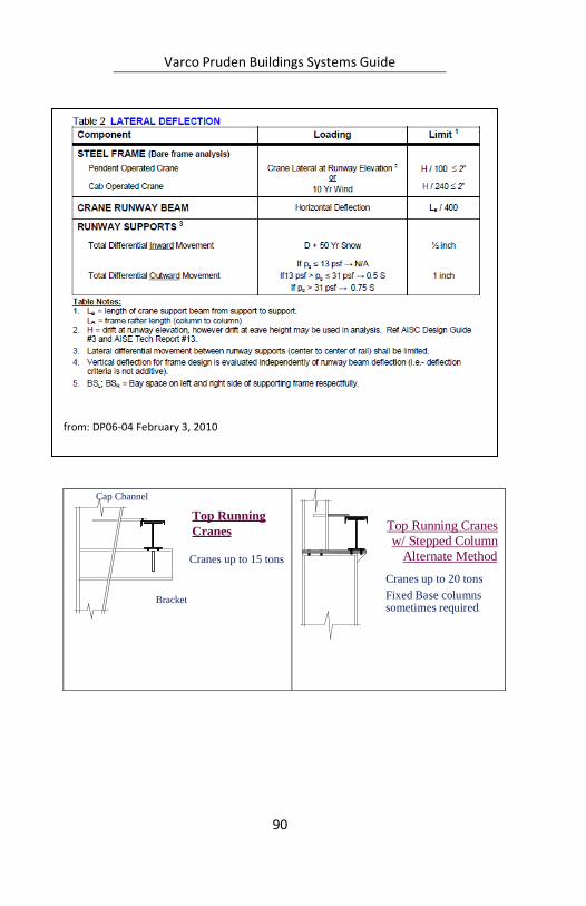
90
Top Running
Cranes
Cranes up to 15 tons
Bracket
Cap Channel
Top Running Cranes w/ Stepped Column
Alternate Method
Cranes up to 20 tons Fixed Base columns
sometimes required
from: DP06-04 February 3, 2010
Varco Pruden Buildings Systems Guide
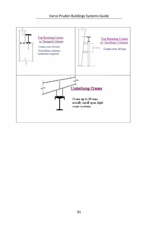
91
Top Running Cranes
w/ Auxiliary Column
Cranes over 20 tons 10' - 15' o.c.
Top Running Cranes w/ Stepped Column
Cranes over 20 tons Fixed Base columns
sometimes required
Varco Pruden Buildings Systems Guide
92
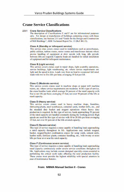
Crane Service Classifications
From: MBMA Manual Section II - Cranes

Varco Pruden Buildings Systems Guide
93
Notes:
Varco Pruden Buildings Systems Guide
94
Notes:
Varco Pruden Buildings Systems Guide
95
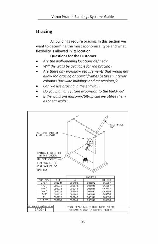
Bracing All buildings require bracing. In this section we
want to determine the most economical type and what flexibility is allowed in its location.
Questions for the Customer
Are the wall-opening locations defined?
Will the walls be available for rod bracing?
Are there any workflow requirements that would not allow rod bracing or portal frames between interior columns (for wide buildings and mezzanines)?
Can we use bracing in the endwall?
Do you plan any future expansion to the building?
If the walls are masonry/tilt-up can we utilize them as Shear walls?
Varco Pruden Buildings Systems Guide
96
Bracing Optimization Concepts
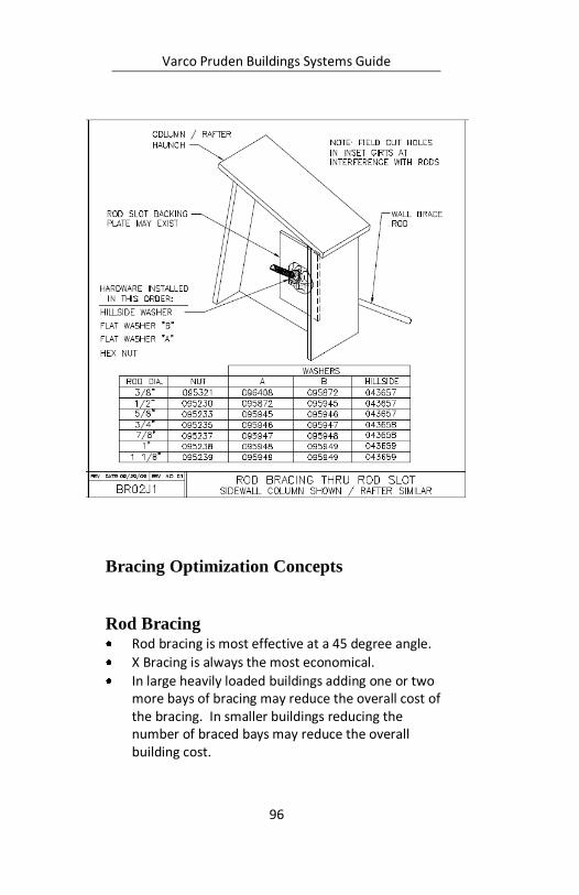
Rod Bracing Rod bracing is most effective at a 45 degree angle.
X Bracing is always the most economical.
In large heavily loaded buildings adding one or two more bays of bracing may reduce the overall cost of the bracing. In smaller buildings reducing the number of braced bays may reduce the overall building cost.

Varco Pruden Buildings Systems Guide
97
Bracing locations can be moved prior to completing the design of the building (not during construction) as long as they stay in the same wall; they do not have to be in the same bay as the roof bay bracing.
Alternate Rod Bracing Relocate rod anchor to the floor.
Connecting a rod to a floor anchor will allow the location of a door or window.
Using one rod in a bay works as long as you have equal numbers of rods each way. They do not have to be in adjacent bays.
Partial Height Rods Most useful when used above openings.
Varco Pruden Buildings Systems Guide
98
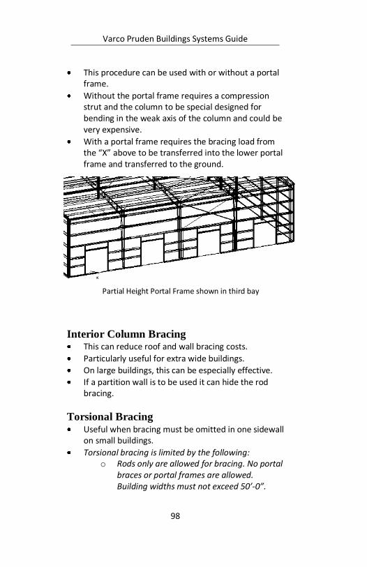
This procedure can be used with or without a portal frame.
Without the portal frame requires a compression strut and the column to be special designed for bending in the weak axis of the column and could be very expensive.
With a portal frame requires the bracing load from the “X” above to be transferred into the lower portal frame and transferred to the ground.
Interior Column Bracing This can reduce roof and wall bracing costs.
Particularly useful for extra wide buildings.
On large buildings, this can be especially effective.
If a partition wall is to be used it can hide the rod bracing.
Torsional Bracing Useful when bracing must be omitted in one sidewall
on small buildings.
Torsional bracing is limited by the following: o Rods only are allowed for bracing. No portal
braces or portal frames are allowed. Building widths must not exceed 50’-0”.
Partial Height Portal Frame shown in third bay
Varco Pruden Buildings Systems Guide
99
o The eave height must not exceed 18’-0”. o The wind speed must not exceed 90 mph. o The roof pitch must not exceed 1:12. o The building must have 3 or more bays. o There cannot be any cranes or mezzanines
or other loads (besides roof top units) applied to the building.
o The building cannot have a lean-to.
Angle Bracing The patterns are the same as rods.
VP Command will automatically select angle bracing if needed.
Standard in high wind and seismic areas.
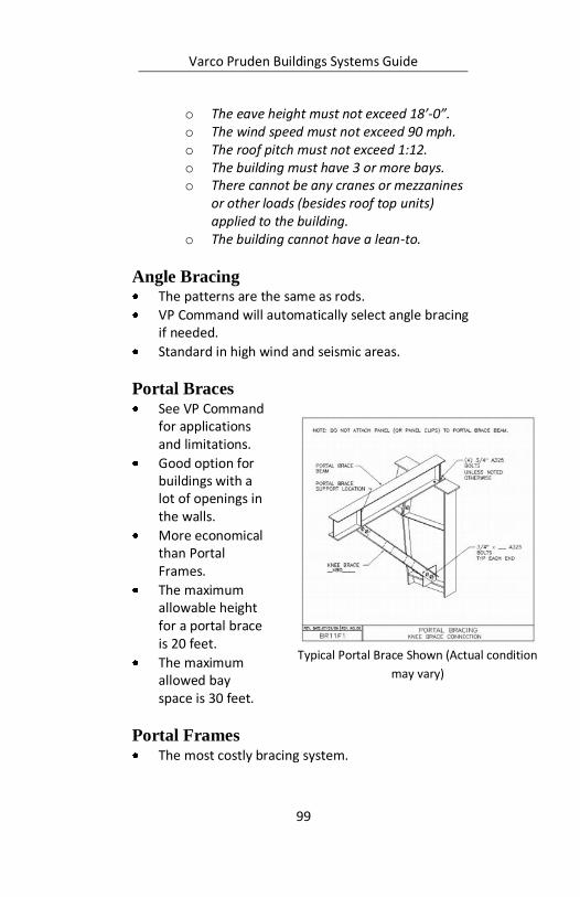
Portal Braces See VP Command
for applications and limitations.
Good option for buildings with a lot of openings in the walls.
More economical than Portal Frames.
The maximum allowable height for a portal brace is 20 feet.
The maximum allowed bay space is 30 feet.
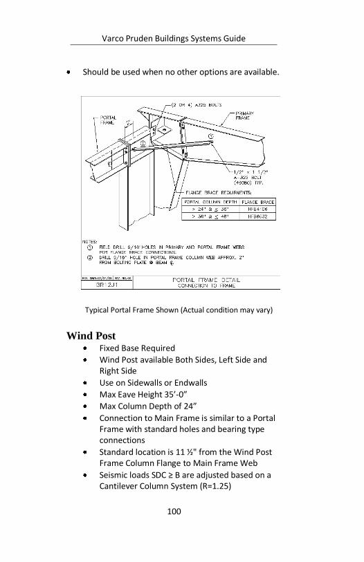
Portal Frames The most costly bracing system.
Typical Portal Brace Shown (Actual condition
may vary)
Varco Pruden Buildings Systems Guide
100
Should be used when no other options are available.
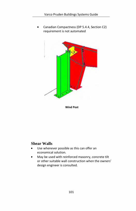
Wind Post Fixed Base Required
Wind Post available Both Sides, Left Side and Right Side
Use on Sidewalls or Endwalls
Max Eave Height 35’-0”
Max Column Depth of 24”
Connection to Main Frame is similar to a Portal Frame with standard holes and bearing type connections
Standard location is 11 ½" from the Wind Post Frame Column Flange to Main Frame Web
Seismic loads SDC ≥ B are adjusted based on a Cantilever Column System (R=1.25)
Typical Portal Frame Shown (Actual condition may vary)
Varco Pruden Buildings Systems Guide
101
Canadian Compactness (DP 5.4.4, Section C2) requirement is not automated
Shear Walls Use whenever possible as this can offer an
economical solution.
May be used with reinforced masonry, concrete tilt or other suitable wall construction when the owners’ design engineer is consulted.
Wind Post

Varco Pruden Buildings Systems Guide
102
Notes:

Varco Pruden Buildings Systems Guide
103
Secondary Secondary is one of the largest components of a
project. The proper selection of the secondary type will impact the economy of the overall project.
VP’s secondary standard is G-30 galvanized steel with an acrylic coating. Bronze, Gray, and Red Oxide are available as options.
Questions for the Customer
Secondary Roof Do you have a requirement for the roofing secondary
that would prevent using purlins or would dictate the use of bar joist?
Do you have Factory Mutual (FM) requirements?
Continuous Purlins at Interior Frame
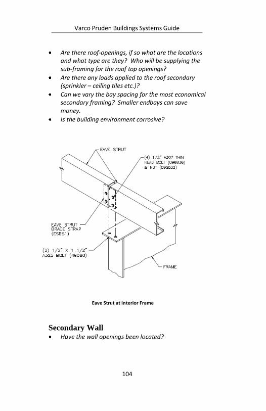
Varco Pruden Buildings Systems Guide
104
Are there roof-openings, if so what are the locations and what type are they? Who will be supplying the sub-framing for the roof top openings?
Are there any loads applied to the roof secondary (sprinkler – ceiling tiles etc.)?
Can we vary the bay spacing for the most economical secondary framing? Smaller endbays can save money.
Is the building environment corrosive?
Secondary Wall Have the wall openings been located?
Eave Strut at Interior Frame
Varco Pruden Buildings Systems Guide
105
If masonry is used on the walls, are they self-supporting walls, or will the walls require support from the building?
Can outset girts be used for economy? Continuous spanning secondary members are typically less expensive than simple span.
Can we use the most economical bay spacing for the wall system?
Is the building environment corrosive? Special coatings for the secondary may need to be considered.
Will wall lights be required?
If liner panels are required are they partial or full height?
What base condition will be required (base girt or base angle)?
Secondary Optimization Concepts Secondary: Roof
The bay spacing that is chosen will affect the price of the secondary, as well as the primary frames. The most economical building solution should consider the combined cost of both the primary and secondary.
As a general rule: 7” purlins (to be used with Panel Rib roof only) may be effectively utilized up to 25’ bays depending on loading.
8 ½” purlins and 10” purlins can be effectively utilized up to 30’ bays (depending upon loading).
11 ½” purlins can be effectively utilized up to 40’ bays (depending upon loading).
When using purlins in lieu of bar joist you have the option of using Panel Rib Roof covering. A floating roof system (SSR, SLR) must be used on bar joists or truss purlins.
Pricing your building(s) multiple ways with VPCommand will insure the most economical result.
Varco Pruden Buildings Systems Guide
106
The below example represents a building 100 W
x 150 L x 20 EH, 50 psf Ground Snow (31.5 roof), 5 bays at 30’-0. Under that heavy snow and large bay the 8 ½” purlins required an intermediate spacing of 4’-0” while the 10” deep purlins designed at the standard 5’-0” spacing. While costing slightly more, the 10” purlins yielded 24 less total purlins, thus saving on erection.
Your actual loading and geometry will affect the outcome of your price. Run various scenarios to get the best results.
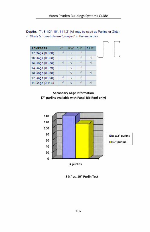
Varco Pruden Buildings Systems Guide
107
8 ½” vs. 10” Purlin Test
0
20
40
60
80
100
120
140
# purlins
8 1/2" purlins
10" purlins
Secondary Gage Information
(7” purlins available with Panel Rib Roof only)
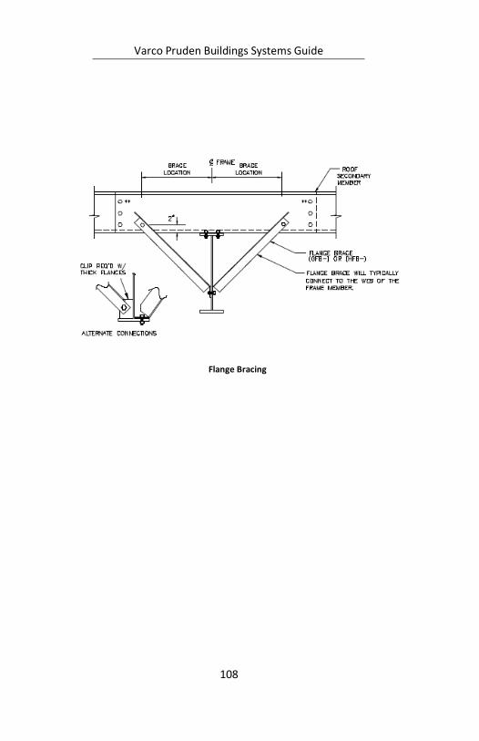
Varco Pruden Buildings Systems Guide
108
Flange Bracing
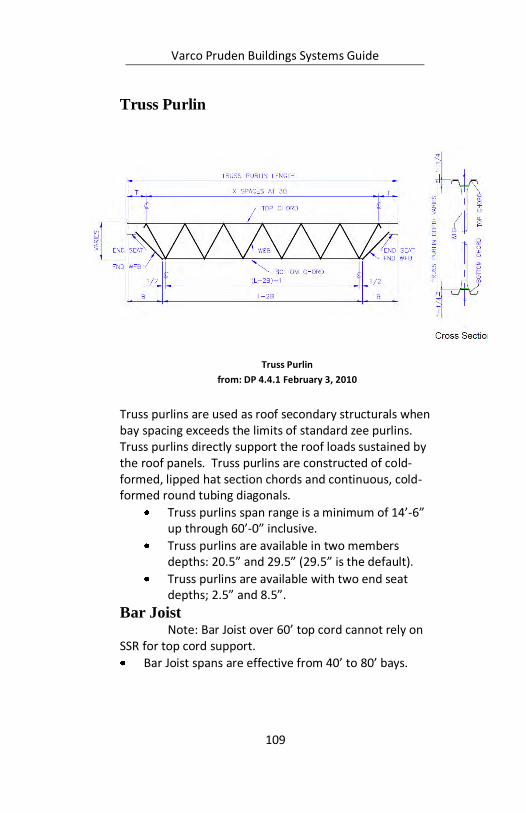
Varco Pruden Buildings Systems Guide
109
Truss Purlin
Truss purlins are used as roof secondary structurals when bay spacing exceeds the limits of standard zee purlins. Truss purlins directly support the roof loads sustained by the roof panels. Truss purlins are constructed of cold-formed, lipped hat section chords and continuous, cold-formed round tubing diagonals.
Truss purlins span range is a minimum of 14’-6” up through 60’-0” inclusive.
Truss purlins are available in two members depths: 20.5” and 29.5” (29.5” is the default).
Truss purlins are available with two end seat depths; 2.5” and 8.5”.
Bar Joist Note: Bar Joist over 60’ top cord cannot rely on
SSR for top cord support.
Bar Joist spans are effective from 40’ to 80’ bays.
Truss Purlin
from: DP 4.4.1 February 3, 2010
Varco Pruden Buildings Systems Guide
110
Bar joist spans of 60’ or greater long span joists must be used. Long span joist are considerably more expensive and should be avoided if possible
Panel Rib cannot be attached to bar joist. The rigidity of the bar joist will eventually cause the fasteners to slot the holes and cause the roof to leak.
When you use Bar Joist you must use SSR, SLR, or composite roof covering.
Purlin spacing can impact your insulation system for the project.
When using bar joist the piping, ductwork, and wiring can be installed within the bar joist system possibly providing additional clearance.
Ceiling Liner panels are not commonly used with bar joist systems. If they are required VP can provide a composite roof system.
FM (Factory Mutual) requirements If you have FM requirements you will have to
comply with special conditions.
Strapping may be required in the end bays.
Additional purlins probably will be required in the edge zones, corner zones, or possibly the entire roof.
VP has solutions for FM I-60, I-75, I-90, I-120 uplift requirements with Standing Seam Roof panels (SSR). Contact your VP Service Center for VP Command input and pricing assistance.
Contact the customer’s insurance carrier to verify minimum requirements.
Roof Openings RTU (Roof Top Unit) locations greatly affect their
price. Accurate location is critical for final pricing and design.
Varco Pruden Buildings Systems Guide
111
Locating RTU’s close to an interior column, or close to the haunch is the most economical location for a roof load.
Who is supplying the sub-framing for the roof top openings?
Are there any collateral loads applied to the roof secondary (sprinkler – ceiling tiles – lighting etc.)?
Roof Loading Application of collateral or point loads on secondary
members requires exact locations to achieve accurate pricing.
When the collateral loading conditions of a portion of the building differ substantially from the base collateral building load, then an area representing the difference should be input into VP Command to optimize the design.
o i.e., Project has 5 lb. collateral load, one area has 8 lb. collateral load – define the area and add the 3 lbs. difference to equal 8. (See Loading section for discussion)
The location of the specified area for a collateral load near a frame line, or an interior column will lower the cost versus a location in center of the bay.
Any special roof covering system impacts the design of the secondary.
If you are using composite roof covering, panel by others, or any non-VP roof covering system contact your VP Service Center.
Use Order Clarification form, section “Cladding not by VP” information, forms are located in the Supplemental Price Book.
Miscellaneous Roof Secondary Concerns Can we vary the bay spacing for the most
economical secondary framing?
Smaller endbays can save costs.
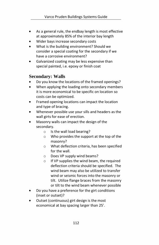
Varco Pruden Buildings Systems Guide
112
As a general rule, the endbay length is most effective at approximately 85% of the interior bay length
Wider bays increase secondary costs
What is the building environment? Should we consider a special coating for the secondary if we have a corrosive environment?
Galvanized coating may be less expensive than special painted, i.e. epoxy or finish coat
Secondary: Walls Do you know the locations of the framed openings?
When applying the loading onto secondary members it is more economical to be specific on location so costs can be optimized.
Framed opening locations can impact the location and type of bracing.
Whenever possible use your sills and headers as the wall girts for ease of erection.
Masonry walls can impact the design of the secondary.
o Is the wall load bearing? o Who provides the support at the top of the
masonry? o What deflection criteria, has been specified
for the wall. o Does VP supply wind beams? o If VP supplies the wind beam, the required
deflection criteria should be specified. The wind beam may also be utilized to transfer wind or seismic forces into the masonry or tilt. Utilize flange braces from the masonry or tilt to the wind beam whenever possible
Do you have a preference for the girt conditions (inset or outset)?
Outset (continuous) girt design is the most economical at bay spacing larger than 25’.
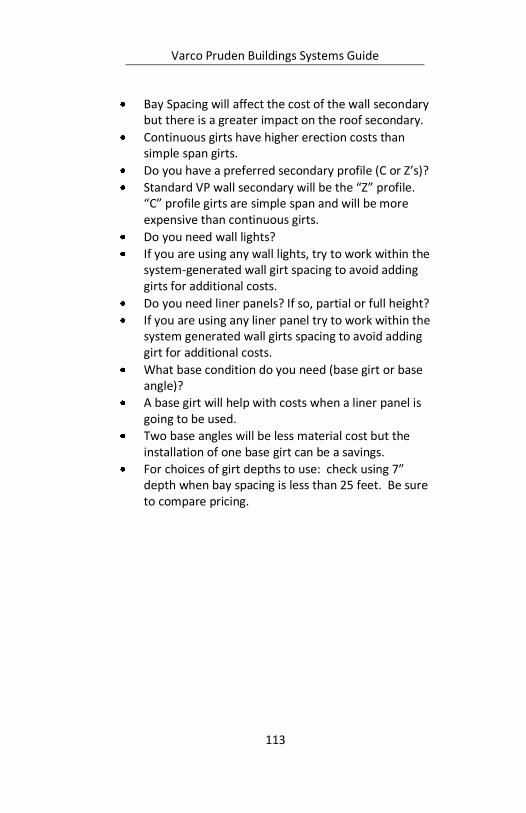
Varco Pruden Buildings Systems Guide
113
Bay Spacing will affect the cost of the wall secondary but there is a greater impact on the roof secondary.
Continuous girts have higher erection costs than simple span girts.
Do you have a preferred secondary profile (C or Z’s)?
Standard VP wall secondary will be the “Z” profile. “C” profile girts are simple span and will be more expensive than continuous girts.
Do you need wall lights?
If you are using any wall lights, try to work within the system-generated wall girt spacing to avoid adding girts for additional costs.
Do you need liner panels? If so, partial or full height?
If you are using any liner panel try to work within the system generated wall girts spacing to avoid adding girt for additional costs.
What base condition do you need (base girt or base angle)?
A base girt will help with costs when a liner panel is going to be used.
Two base angles will be less material cost but the installation of one base girt can be a savings.
For choices of girt depths to use: check using 7” depth when bay spacing is less than 25 feet. Be sure to compare pricing.
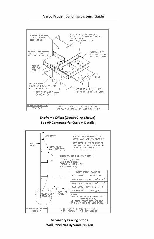
Varco Pruden Buildings Systems Guide
114
Endframe Offset (Outset Girst Shown)
See VP Command for Current Details
Secondary Bracing Straps
Wall Panel Not By Varco Pruden
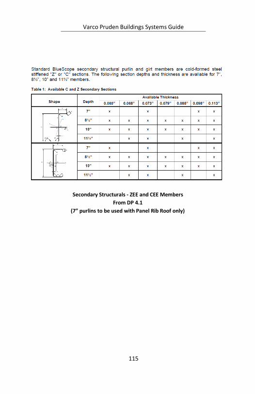
Varco Pruden Buildings Systems Guide
115
Secondary Structurals - ZEE and CEE Members
From DP 4.1
(7” purlins to be used with Panel Rib Roof only)
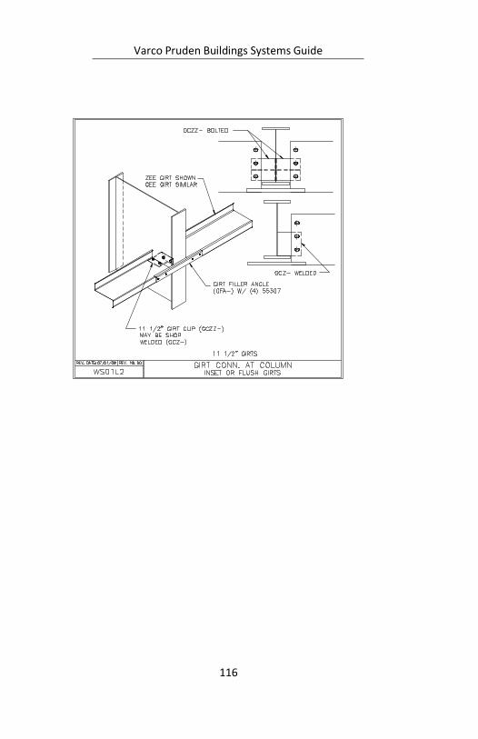
Varco Pruden Buildings Systems Guide
116

Varco Pruden Buildings Systems Guide
117
Notes:

Varco Pruden Buildings Systems Guide
118
Notes:
Varco Pruden Buildings Systems Guide
119
Framed Openings Framed openings are required in metal panel
walls for doors, windows, vents, louvers, etc. What we want to determine in this section is the
quantity and location for all required wall openings. Questions for the Customer
How many, what size and will framed openings be required?
What types of doors are required?
Will the doors be supplied by VP or others?
Are there any future or field located openings?
Framed Opening Optimization Concepts Set the jamb extension to terminate into the first girt
above the header elevation. Every time a continuous girt is interrupted you add material cost to the secondary members.
Accurately locating the opening(s) during estimating can save you money in the long run. If possible, do not locate an opening within 2’ of a column centerline to allow for column flange brace.
When possible locate openings to allow rod bracing in sidewall.

Varco Pruden Buildings Systems Guide
120
Notes:
Varco Pruden Buildings Systems Guide
121
Openings Openings are created in VPCommand when
multiple buildings are joined together – creating the opening(s) at the common wall(s). The default for VPC is to remove all material (secondary, panel, insulation) so that one could literally walk through the common area. You can put this material back in by changing the parameters within the Openings folder of VPC. If you need to remove material for items such as brick, block, masonry, glass, or actually open you should create these at the “Covering” level(s) of VPC.
Questions for the Customer
Are there any areas of the building wall that are open to the elements (no wall covering or secondary) such as covered loading docks?
Are there any building layouts that will be abutting each other?
Will there be covering or wall material on the common wall?
Opening Optimization Concepts Areas that are open to the air will change the
loading of the building and will also be of importance to the mechanical equipment supplier if heating or air movement is involved.
In VP Command, when buildings abut (having common wall regions), the common wall is considered open unless it is changed to include common wall material. This condition is important to understand when pricing the project since loads are removed from the opening.
When putting material back in an opening, be aware that VP Command has created an opening at each touching surface. Only change the parameters of the opening on the wall in which you wish to be sheeted – do

Varco Pruden Buildings Systems Guide
122
not revise both facing openings or you will have sheeting and girts face-to-face.
This project shows “openings” at the common walls where the Lean-tos
meet the sidewalls of the main structure. (Note: VPCommand will show
the open portion in a Salmon color. Emphasis added to this graphic for
clarity.

Varco Pruden Buildings Systems Guide
123
Notes:
Varco Pruden Buildings Systems Guide
124
Covering
What is the most economical way to supply covering that meets the owner’s requirements and the desired appearance? As noted in the previous section on “Openings” if you require material that is not supplied by VP (brick, glass, etc.) you should input these at the “Covering” level of VPC and not at the “Openings” level.
Covering Questions for the Customer
Roof Covering
What type of roof covering is required for your building?: Panel Rib (PR), Standing Seam Roof (SSR), Architectural profile (SLR-type), membrane?
Is a specific color / finish required?
Standard VP Color?
Special Color?
What is the roof pitch for the building? Panel Rib Roof minimum is ½:12; SSR and SLR minimums are ¼:12.
Wall Covering
What type of wall covering do you need for your building?: Architectural profile, PR, Stranloc (available through VP Components), Vee-Rib, etc.?
Masonry?
Concrete Tilt Wall?
Stud Construction?
Curtain Wall?
Is the wall a specific color / finish required?
Standard VP Color / finish?
Special Color / finish?
Varco Pruden Buildings Systems Guide
125
Covering Optimization Concepts
Most economical is the lightest gauge.
Utilize standard colors as much as possible.
Verify what warranties are required for the panel finishes.
KXL performance is better than SP. SP finish available with Liner Panel only.
Controlling sheet lengths in order to eliminate a lap can be cost effective, especially for Standing Seam Roof (SSR). Panel lengths over 48’ may require special freight.
Choose the most economical panel type for the building. For example, Panel Rib roof may be an economical choice in lieu of SSR depending on the use of the building
Trim packages vary with the panel.
Panels not by VP may increase the cost of secondary support members and may require additional secondary strapping.
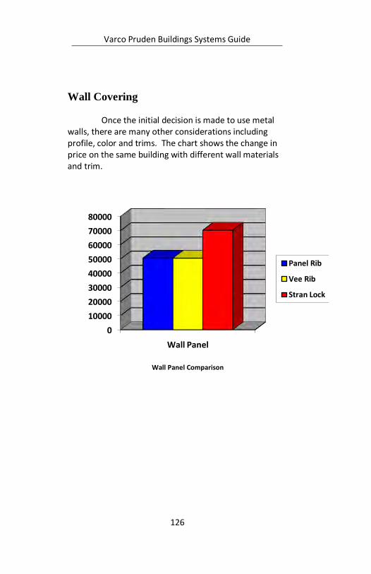
Varco Pruden Buildings Systems Guide
126
Wall Covering Once the initial decision is made to use metal
walls, there are many other considerations including profile, color and trims. The chart shows the change in price on the same building with different wall materials and trim.
Wall Panel Comparison
0
10000
20000
30000
40000
50000
60000
70000
80000
Wall Panel
Panel Rib
Vee Rib
Stran Lock
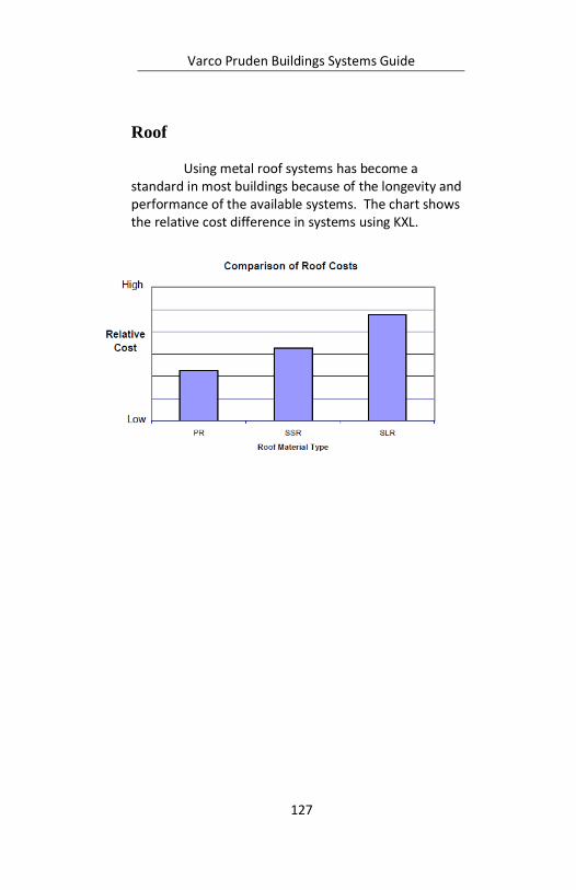
Varco Pruden Buildings Systems Guide
127
Roof Using metal roof systems has become a
standard in most buildings because of the longevity and performance of the available systems. The chart shows the relative cost difference in systems using KXL.

Varco Pruden Buildings Systems Guide
128
Notes:
Varco Pruden Buildings Systems Guide
129
Liner Liner may be required to protect the interior
surfaces (covering, girts, frames and insulation), and to also provide a finished appearance to the building.
Questions for the Customer
What is the purpose of the liner?
Will a liner be used at the roof or will the walls be the only liner panel requirement?
What type material (wood, metal, etc.) is being used?
If metal, what gauge panel is required?
What is the height of the liner panel?
Will the bracing interfere with the liner panel?
Will the wall rods have to be cut through the girts or do we go to another type of bracing?
Will flange braces fastened through the liner panel be allowed? Removal of flange braces will make the columns or rafters unsupported which will make them more expensive. If you only require no flange bracing at a partial height liner condition, state so, and allow flange bracing above for more economical framing.
Liner Panel Optimization Concepts Most economical is the lightest, 28 gauge, liner
available.
Utilize standard colors as much as possible.
Verify what warranties are required for the panel finishes. Use SP finish as much as possible.

Varco Pruden Buildings Systems Guide
130
Notes:
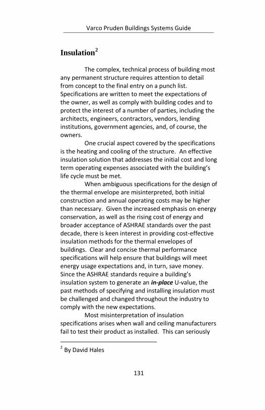
Varco Pruden Buildings Systems Guide
131
Insulation2
The complex, technical process of building most
any permanent structure requires attention to detail from concept to the final entry on a punch list. Specifications are written to meet the expectations of the owner, as well as comply with building codes and to protect the interest of a number of parties, including the architects, engineers, contractors, vendors, lending institutions, government agencies, and, of course, the owners.
One crucial aspect covered by the specifications is the heating and cooling of the structure. An effective insulation solution that addresses the initial cost and long term operating expenses associated with the building’s life cycle must be met.
When ambiguous specifications for the design of the thermal envelope are misinterpreted, both initial construction and annual operating costs may be higher than necessary. Given the increased emphasis on energy conservation, as well as the rising cost of energy and broader acceptance of ASHRAE standards over the past decade, there is keen interest in providing cost-effective insulation methods for the thermal envelopes of buildings. Clear and concise thermal performance specifications will help ensure that buildings will meet energy usage expectations and, in turn, save money. Since the ASHRAE standards require a building’s insulation system to generate an in-place U-value, the past methods of specifying and installing insulation must be challenged and changed throughout the industry to comply with the new expectations.
Most misinterpretation of insulation specifications arises when wall and ceiling manufacturers fail to test their product as installed. This can seriously
2 By David Hales
Varco Pruden Buildings Systems Guide
132
affect the heating and cooling of a building. It is not enough to test the insulation in a standard environment; it must be tested as actually installed on the building. This is commonly referred to as an in-place testing method.
The key is to maintain a close relationship with your mechanical contractors and engineers. When they read a certain specification for insulation, they usually assume it to be an in-place value. If the insulation they are considering does not have an in-place value, then the amount of insulation specified would be incorrect. The engineer must then over compensate the HVAC design for the reduced performance of the improperly tested insulation in order to sufficiently heat and cool the building. This can quickly increase the life-cycle cost of operations in the building. There are many software packages available making it easier to run several insulating options to identify the most economic solution.
It is important for the specifying community to become more educated on the performance of various insulation materials, systems and installation practices so
Varco Pruden Buildings Systems Guide
133
this does not happen. The key to solving this problem is to insist on in-place values that are substantiated by a recognized testing agency. A Hot Box test procedure can accurately determine how an entire system will perform once constructed.
In-Place Values The following reflect the in-place values of VP
Buildings’ roof and wall assemblies with various material and installation methods. All faced insulation used in these test results possessing the NAIMA 202-96 quality designation and was laminated under strict adherence to the National Insulation Association’s (NIA) 404 standards:
Panel Rib Roof with 3” of faced blanket insulation R= 7.7 (single layer over purlin)
Panel Rib Roof with 4” of faced blanket insulation R= 8.4 (single layer over purlin)
Panel Rib Roof with 6” of faced blanket insulation R= 12.7 (single layer over purlin)
Panel Rib Wall (Vee Rib) with 3” of faced blanket insulation R= 7.6 (single layer over girt)
Panel Rib Wall (Vee Rib) with 4” of faced blanket insulation R= 8.3 (single layer over girt)
Panel Rib Wall (Vee Rib) with 6” of faced blanket insulation R= 12.6 (single layer over girt)
SSR Roof with 3” of faced blanket insulation, no Thermal Block R= 9.5 (single layer over purlin)
SSR Roof with 4” of faced blanket insulation, no Thermal Block R= 11.3 (single layer over purlin)
SSR Roof with 6” of faced blanket insulation, no Thermal Block R= 12.6 (single layer over purlin)
SSR Roof with 3” of faced blanket insulation and Thermal Block R= 10.3 (single layer over purlin w/Thermal Block)
SSR Roof with 4” of faced blanket insulation and Thermal Block R= 12.3 (single layer over purlin w/Thermal Block)
Varco Pruden Buildings Systems Guide
134
SSR Roof with 6” of faced blanket insulation and Thermal Block R= 15.8 (single layer over purlin w/Thermal Block)
SSR Roof with 6” of blanket insulation and a 3” SuperBlock R= 19.0 (4” faced layer over purlin, and 2” unfaced layer over SuperBlock)
SSR Roof with 7” of blanket insulation and a 3” SuperBlock R= 22.8 (4” faced layer over purlin, and 3” unfaced layer over SuperBlock)
Another important factor when installing
insulation is to determine the proper vapor retarder that needs to be applied. The “perm” rating associated with the facing indicates the rate of vapor transmission through the material. The best rating in the metal building industry is a .02. It provides a significant vapor retarder that is required to keep the insulation dry and capable of performing at an optimum level.
Insulation Considerations Here is a checklist of things to remember when
working on future projects:
Understand the code requirements for each project. Just because you erect several buildings in the same geographical market does not mean that they have the same insulation requirements.
Make sure the insulation is specified to represent an in-place value that is supported by ASTM Hot Box testing procedures.
Challenge the insulation specifications that are vague and ambiguous.
Insist on using fiberglass insulation that is manufactured, laminated and is certified to possess the NAIMA 202-96 and NIA 404 quality standards.
Varco Pruden Buildings Systems Guide
135
Consider VP’s 6” SuperBlock system when installing roof insulation. It has a tested in-place R-19 value and is protected by U.S. Patents.
A seven-inch system is also available. It has a tested in-place value of 22.8 and meets ASHRAE roof standards for all states except some locations in Alaska.
“R” and “U” values are the reciprocal of each other.
Contact your VP District Manager or Laminator to assist you in understanding the various insulating options through the VP Buildings Insulation program.
VII. Building Energy Conservation3
7.1 General Energy conservation is an important consideration for building owners and designers that is regulated through local and national codes. These codes are evolving, becoming more stringent, and being better enforced. Understanding energy conservation requires a basic understanding of the theory, terms, and construction practices. Good planning and proper use of energy conservation principles will pay off in long-term economic gains for the owner, comfort for the occupants and reductions in maintenance and modification to the building as it ages.
7.1.1 Heat Transfer Fundamentals Heat transfer is the term commonly used to indicate the movement of heat (energy) from one region to another.
3 Section VII Building Energy Conservation from: Metal
Building Systems Manual. 2006. Cleveland, Ohio.
Varco Pruden Buildings Systems Guide
136
Minimizing heat transfer is the role that insulating materials play in conserving energy. The driving force for heat transfer is the difference in temperature between two regions, or surfaces, and will occur in a direction from hot to cold. The three basic mechanisms of heat transfer are as follows: 1) Conduction - the process by which heat will transfer through a solid material. Heat will transfer through the material from hot to cold by means of molecular contact. 2) Convection - the transfer of heat by means of a moving fluid such as air or water. Heat is picked up by a moving fluid and transported to another region. 3) Radiation - the transfer of heat by means of electromagnetic waves.
7.1.2 Measurement of Heat Transfer The amount of heat transferred is measured in British Thermal Units (BTU). One BTU is equivalent to the amount of energy required to raise one pound of water by one degree Fahrenheit (F). Several interrelated properties are used to measure the ability of a material to permit heat flow through it. Thermal conductance (C) is a measure of the rate (measured in BTU's per hour) that heat will flow through an insulating material. Materials that have lower conductance values will allow less heat to flow through them. Thermal resistance (R) is a measure of a material's ability to resist the passage of heat. Thermal resistance is often expressed using the common term “R-value”. Materials with higher resistance values allow less heat to flow through them. Thermal resistance is the reciprocal of the thermal conductance. For multi-layer systems, the total resistance (Rt) is the sum of the individual resistance of each layer. Thermal transmittance (U) is the total rate that heat will flow through a given assembly including the effects of
Varco Pruden Buildings Systems Guide
137
surface air film resistances. Thermal transmittance is often expressed using the common term “U-value” or “U-factor”. A lower U-value indicates that less heat will flow through an assembly. Thermal transmittance (U) is the reciprocal of the total thermal resistance, Rt.
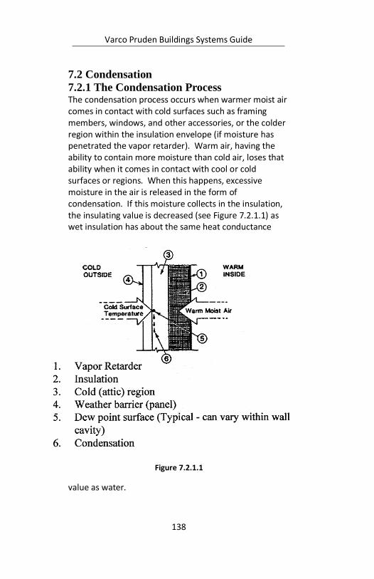
Varco Pruden Buildings Systems Guide
138
7.2 Condensation
7.2.1 The Condensation Process The condensation process occurs when warmer moist air comes in contact with cold surfaces such as framing members, windows, and other accessories, or the colder region within the insulation envelope (if moisture has penetrated the vapor retarder). Warm air, having the ability to contain more moisture than cold air, loses that ability when it comes in contact with cool or cold surfaces or regions. When this happens, excessive moisture in the air is released in the form of condensation. If this moisture collects in the insulation, the insulating value is decreased (see Figure 7.2.1.1) as wet insulation has about the same heat conductance
value as water.
Figure 7.2.1.1
Varco Pruden Buildings Systems Guide
139
Method of Condensation In dealing with condensation, air may be considered to be a mixture of two gasses - dry air and water vapor. One thousand cubic feet of air at 75° F can hold up to 1.4 pints of water. At 45° F, the same volume of air can hold only 0.5 pints. Relative humidity is a percentage measurement of the amount of water vapor present in the air in relation to the amount it is capable of holding at that temperature. For example, 50% relative humidity indicates the air is carrying one-half of the maximum amount of moisture that it is capable of containing at the given temperature. Cold, outside air is usually much drier than warm inside air. Therefore, the indoor relative humidity can be lowered by bringing in outside air to mix with and dilute the moist inside air. At 100% relative humidity, the air is “saturated.” The temperature at which the air is saturated and can no longer hold the moisture is called the dew point temperature (see Table 7.2.4.1 for more information). Whenever air temperature drops below its dew point, excess moisture will be released in the form of condensation. Condensation problems are most likely to occur in climates where temperatures frequently dip to 35° F or colder over an extended period of time.
7.2.2 Condensation Control Two things must be present for condensation to occur: warm moist air, and cool surface temperatures below the dew point. The proper control of these two factors can minimize condensation. In metal building systems, we are concerned with two different areas or locations: visible condensation which occurs on surfaces below dew point temperatures; and concealed condensation which occurs when moisture has passed into interior regions and then condenses on a surface below dew point temperature.
Varco Pruden Buildings Systems Guide
140
7.2.2.1 Visible Condensation To effectively control visible condensation, it is necessary to reduce the cold surface areas where condensation may occur. It is also important to minimize the air moisture content within a building by the use of properly designed ventilating systems.
7.2.2.2 Concealed Condensation Concealed condensation is the most difficult to deal with and can be the most damaging to any kind of structure. This type of condensation may be controlled in metal buildings by the proper use of vapor retarders and by minimizing moisture content within the building by proper ventilation. Additional condensation control can be accomplished by venting the cavities of the walls and roof.
7.2.3 Vapor Retarders A vapor retarder is used to inhibit the passage of warmer moist air into the inner regions of the roof or wall system. The proper selection and installation of the vapor retarder can help control condensation problems in a building. Vapor retarders are rated by the amount of moisture that can pass through them. The lower this rating, called a perm rating, the less vapor transmission will occur and the more effective the vapor retarder will be. There are various types of vapor retarders available, such as: 1. Structural Membranes, including rigid steel sheets or other impermeable material. 2. Flexible Membranes, such as foils, coated papers, or plastic films. Usually, these membranes are rated by “perm” of 1.0 or less, per ASTM E-96. (The most familiar to the metal building industry are the membrane retarders laminated to fiberglass blanket insulation). Plain white vinyl with a perm rating of 1.0 is not an
Varco Pruden Buildings Systems Guide
141
effective vapor retarder, especially in buildings with a high relative humidity. 3. Coating Membranes, which includes paints.
Proper Sealing of the Vapor Retarder 1. When installing either a membrane type or
structural type, make sure that all seams, laps and joints are properly sealed. Sealing a vapor retarder may be achieved by gluing, taping, overlapping, or stapling according to the insulation supplier’s recommendations.
2. In the case of a membrane type retarder, make sure that any punctures or tears in the material are repaired.

Varco Pruden Buildings Systems Guide
142
Notes:
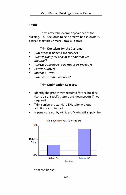
Varco Pruden Buildings Systems Guide
143
Trim Trims affect the overall appearance of the
building. This section is to help determine the owner’s desire for simple or more complex details.
Trim Questions for the Customer
What trim conditions are required?
Will VP supply the trim at the adjacent wall material?
Will the building have gutters & downspouts?
Exterior Gutters
Interior Gutters
What color trim is required?
Trim Optimization Concepts
Identify the proper trim required for the building (i.e., do not specify gutters and downspouts if not required).
Trim can be any standard KXL color without additional cost impact.
If panels are not by VP, identify who will supply the
trim conditions.

Varco Pruden Buildings Systems Guide
144
If SMACNA4 trim detailing is required, it is available from AEP-Span at an additional cost.
Avoid interior gutter if possible.
4 SMACNA – Sheet Metal and Air Conditioning
Contractor’s National Association
Varco Pruden Buildings Systems Guide
145
Trim Conditions
The following represent some common VP trim conditions. Please see the Standard Erection Details (SEDs) for actual condition.
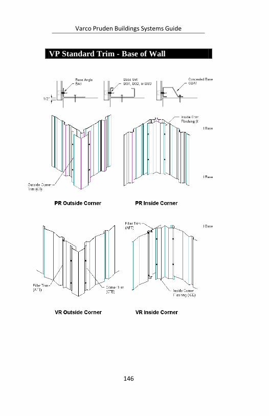
Varco Pruden Buildings Systems Guide
146
VP Standard Trim - Base of Wall
VP Standard Trim - Corners
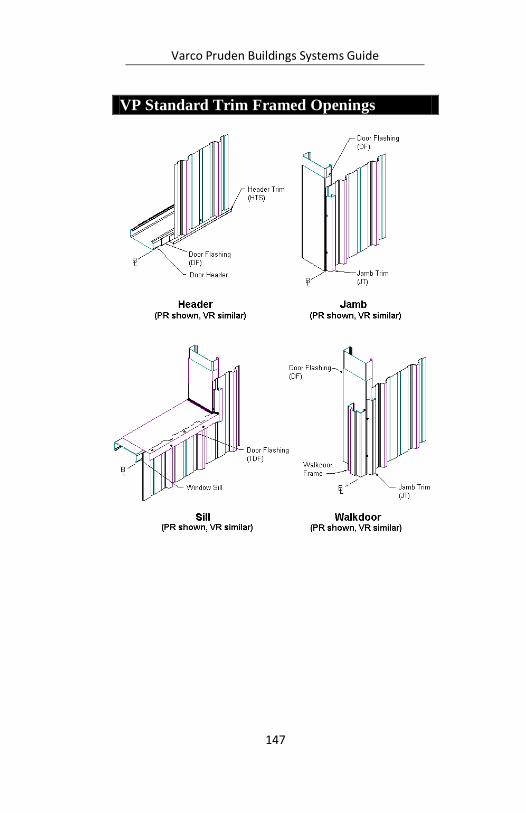
Varco Pruden Buildings Systems Guide
147
VP Standard Trim Framed Openings

Varco Pruden Buildings Systems Guide
148
VP Standard Trim - PR Low Eave
VP Standard Trim - SSR Low Eave
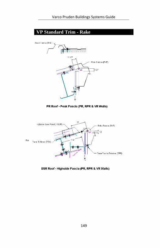
Varco Pruden Buildings Systems Guide
149
VP Standard Trim - Rake
VP Standard Trim - High Eave
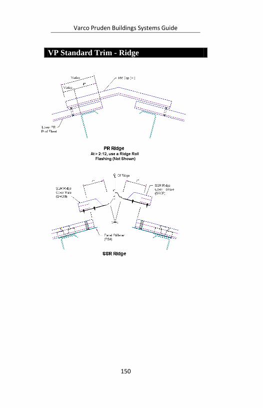
Varco Pruden Buildings Systems Guide
150
VP Standard Trim - Ridge
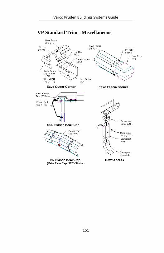
Varco Pruden Buildings Systems Guide
151
VP Standard Trim - Miscellaneous
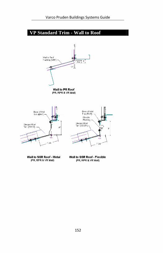
Varco Pruden Buildings Systems Guide
152
VP Standard Trim - Wall to Roof
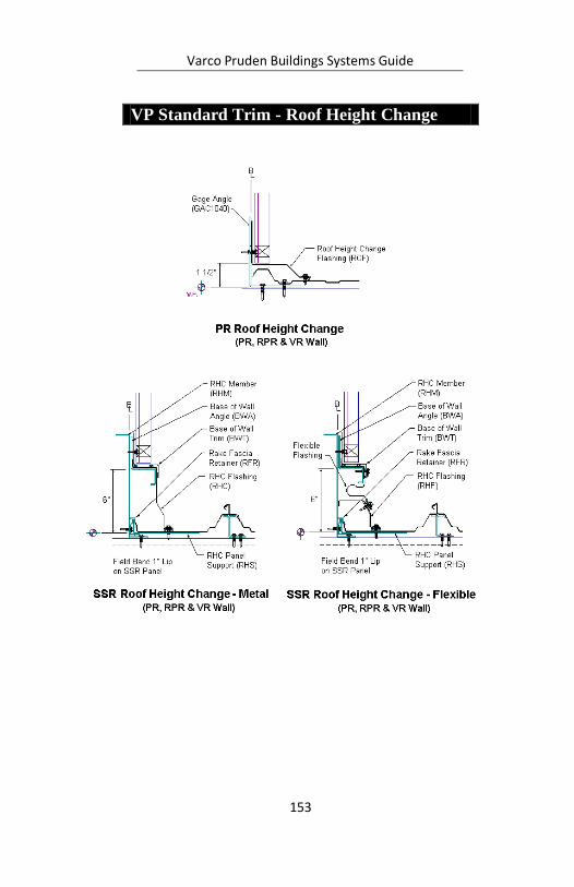
Varco Pruden Buildings Systems Guide
153
VP Standard Trim - Roof Height Change
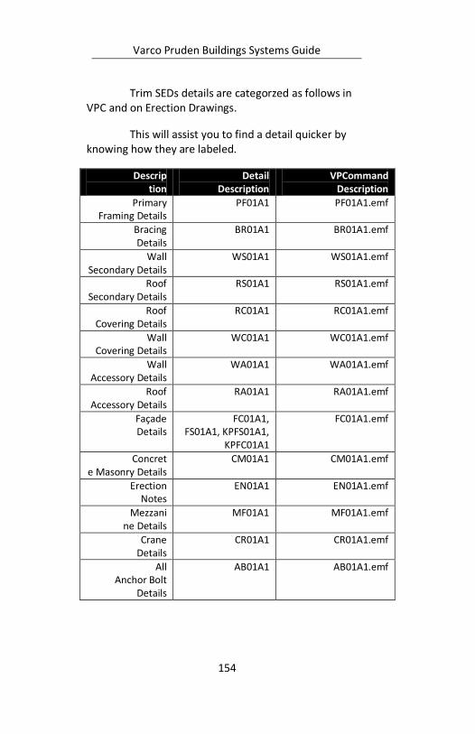
Varco Pruden Buildings Systems Guide
154
Trim SEDs details are categorzed as follows in VPC and on Erection Drawings.
This will assist you to find a detail quicker by knowing how they are labeled.
Description
Detail Description
VPCommand Description
Primary Framing Details
PF01A1 PF01A1.emf
Bracing Details
BR01A1 BR01A1.emf
Wall Secondary Details
WS01A1 WS01A1.emf
Roof Secondary Details
RS01A1 RS01A1.emf
Roof Covering Details
RC01A1 RC01A1.emf
Wall Covering Details
WC01A1 WC01A1.emf
Wall Accessory Details
WA01A1 WA01A1.emf
Roof Accessory Details
RA01A1 RA01A1.emf
Façade Details
FC01A1, FS01A1, KPFS01A1,
KPFC01A1
FC01A1.emf
Concrete Masonry Details
CM01A1 CM01A1.emf
Erection Notes
EN01A1 EN01A1.emf
Mezzanine Details
MF01A1 MF01A1.emf
Crane Details
CR01A1 CR01A1.emf
All Anchor Bolt
Details
AB01A1 AB01A1.emf

Varco Pruden Buildings Systems Guide
155
For example, if I was looking for a detail on Primary Framing I would look at SEDs starting with PF.

Varco Pruden Buildings Systems Guide
156
Notes:

Varco Pruden Buildings Systems Guide
157
Notes:
Varco Pruden Buildings Systems Guide
158
Liner Trim Liner trim is to protect and hide the raw edges
of the panels. This is an appearance option and needs to be determined if it is desired by the owner.
Trim Questions for the Customer
Will interior trim be required where liner panels are required?
How detailed will the trim requirement be on the interior of the building?
Liner Trim Optimization Concepts Interior liner trim is not required in many
installations. Be sure it is a requirement of the project before it is added.
If it is required, determine how elaborate the requirement will be.
In VP Command the liner can include the soffit of any overhangs, so be careful to include what is required in these areas.

Varco Pruden Buildings Systems Guide
159
Notes:
Varco Pruden Buildings Systems Guide
160
Accessory A wide range of accessories are available. The
purpose of this section is to determine the quantity, location and types of accessories required.
Accessory Questions for the Customer
What types and quantities of door/windows should VP supply?
What type of door hardware is required?
Do you want wall-lights on the building?
Will there be louvers on the building?
What type roof curbs, ridge vents, tuf-lites or skylights will VP provide on this project?
Are there any other “Special“ accessories VP can supply?
Accessory Optimization Concepts VP doors and windows usually do not require framed
openings.
Door hardware is expensive; make sure you understand what will be required.
While accessories will increase the cost of a building, they also offer another area in which the service to the customer can be enhanced. Don’t overlook the ability to provide any accessory that is required. VP Components5 can greatly assist with special accessory needs.
5 VP Components: phone – 877-983-7663;
www.vpcomp.com

Varco Pruden Buildings Systems Guide
161
Notes:
Varco Pruden Buildings Systems Guide
162
Pricing The purpose of this section is to determine any
optional warranty costs that may be required that influence the price of the project.
Warranty Warranty Questions for the Customer
Are Warranties other than the standard material warranties required?
o Weather tight warranty o Optima Warranty
What Warranties are required on the panel finish o SP 10 year finish (for liner panel only) o SP 20 year finish (for liner panel only) o KXL 20 year finish
Warranty Optimization Concepts The cost of warranties should never be included
in a project unless it is a requirement to satisfy the owner. Make sure you understand VP Buildings’ offering in this area.
Also, make sure you understand your involvement in the warranty when it is offered.
See the Warranties section within the Supplemental Price Book section of Order Entry for the latest offerings.

Varco Pruden Buildings Systems Guide
163
Notes:
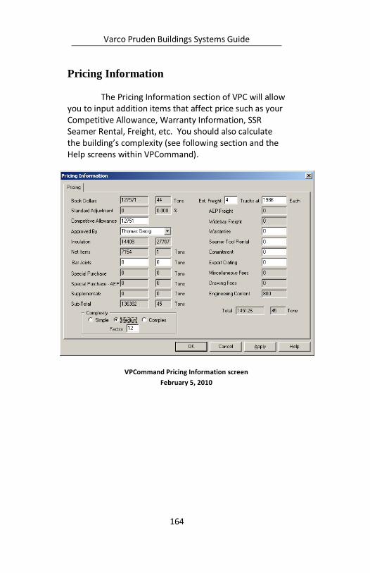
Varco Pruden Buildings Systems Guide
164
Pricing Information The Pricing Information section of VPC will allow
you to input addition items that affect price such as your Competitive Allowance, Warranty Information, SSR Seamer Rental, Freight, etc. You should also calculate the building’s complexity (see following section and the Help screens within VPCommand).
VPCommand Pricing Information screen
February 5, 2010
Varco Pruden Buildings Systems Guide
165
Metal Buildings Manfacturer’s Association
Complexity
MBMA Complexity - Simple A rectangular building w/ solid web frames,
purlins on the roof (any depth), SSR or PR roof panel, solid sheeted walls (PR or VR), double or single slope roof, standard rod bracing, user imposed point loads allowed, and any standard accessories. Standard Building Accessories:
Walk doors, windows, louvers, skylights, vents, liner panels, eave gutter, etc.
MBMA Complexity - Medium A building with any Category "B" or "C" items,
but no more than (8) complexity points. Category "B" Items (Each one counts as 2
complexity points) Open web frames, facades (vertical & mansard),
skewed end walls, South FL code, SLR roof, canopies over 10'-0", concealed fastener wall (Span Loc, etc.), cranes up to 20 ton (class "C") perpendicular to frames, roof extensions over 8'-0", masonry wind beams, sliding door (max 20' x 20'), furnish mezzanine system, monorails not perpendicular to the frames, roof height change, parapets, partitions, mini-warehouse.
Category "C" Items (Each one counts as 4
complexity points) Special facades, skewed sidewalls, single hip, single valley, single jack beam, hanger doors, bi-fold doors, dormers, cranes under 20 ton (class "C") not
Varco Pruden Buildings Systems Guide
166
perpendicular to frames, cranes over 20 ton (class "C") perpendicular to frames.
MBMA Complexity - Complex A building with any Category "D" items, or more
than (8) complexity points. Category "D" Items (Each one counts as 8
complexity points) Both skewed sidewalls & end walls, cranes over 20 ton
not running perpendicular to the frames, any class "D"
crane multiple hips or valleys, multiple jack beams,
octagon shapes, multiple level mezzanines.
MBMA Complexity - Factor
Total number of Complexity Points. Category "B" Items (Each one counts as 2
complexity points) Open web frames, facades (vertical & mansard),
skewed end walls, South FL code, SLR roof, canopies over 10'-0", concealed fastener wall (Span Loc, etc.), cranes up to 20 ton (class "C") perpendicular to frames, roof extensions over 8'-0", masonry wind beams, sliding door (max 20' x 20'), furnish mezzanine system, monorails not perpendicular to the frames, roof height change, parapets, partitions, mini-warehouse.
Category "C" Items (Each one counts as 4
complexity points) Special facades, skewed sidewalls, single hip,
single valley, single jack beam, hanger doors, bi-fold doors, dormers, cranes under 20 ton (class "C") not perpendicular to frames, cranes over 20 ton (class "C") perpendicular to frames.
Varco Pruden Buildings Systems Guide
167
Category "D" Items (Each one counts as 8 complexity points)
Both skewed sidewalls & end walls, cranes over
20 ton not running perpendicular to the frames, any class "D" crane multiple hips or valleys, multiple jack beams, octagon shapes, multiple level mezzanines.

Varco Pruden Buildings Systems Guide
168
Notes:
Varco Pruden Buildings Systems Guide
169
Other Topics These topics may be outside the normal input of
VP Command, and may require consultation with VP for pricing. The purpose of this section is to determine if these elements are required in the project. Refer to VP’s order clarification documents to assist with these additional building features.
Questions for the Customer
Mezzanines Is there a mezzanine or elevated floor in the project?
If there is a Mezzanine is it supported by our building structure or is it an independent structure?
What will the mezzanine be used for (this will control the design live load)?
Will stairwell openings be required? If so, what size and location?
What will the Mezzanine floor material be? o Poured concrete (thickness) o Lightweight concrete (thickness) o Gypsum o Grating o Steel Plate o Wood
Can the mezzanine be used to help brace the building?
What are the required clearances for the mezzanine
Finished Floor elevation
Clearance below the mezzanine steel
Clearance above the mezzanine to bottom of roof
Facades and Parapets
Varco Pruden Buildings Systems Guide
170
See previous sections on facades and parapets for more informaiton.
What is the reason for having a Façade/Parapet? o Is it an architectural element? o Designed to enhance the look of the
building? o Is it to cover Roof Top Units (RTU) and/or
roof slope?
What type of material is used for construction of the Façade/Parapet?
o Define the geometry of the Façade/Parapet, i.e., open or closed, mansard vs. straight.
o Height? o Projection? o Etc.
Partitions What is the function of the Partition wall?
o Fire protection. o Noise reduction. o Restrict or control air flow and/or smoke o Insulate portion of the building.
Other Topics Optimization Concepts
Mezzanines can be a major element of the building project. Find out as much as you can from the owner about what he needs, then determine the best approach to providing the mezzanine. If it is to be by VP, the framing of the materials will be critical to the economy of the building.
Facades and parapets may be required to change the appearance of the building or to make a statement in the marketplace. They may be to support signs or to provide a required appearance of the building.
Varco Pruden Buildings Systems Guide
171
Whatever the reason, they can be an expensive element of the building. In addition, there are some methods of constructing Facades that are more expensive than others. Before quoting the more expensive alternatives, make sure they are required.
Partitions are usually required to separate functional areas in a building. The proper application of materials is necessary to provide the best solution. VP can provide partitions with metal panels. If other materials are required, it may be more economical to use metal studs to achieve the partition.
Varco Pruden Buildings Systems Guide
172
Additional VP Command (VPC) Items6
Building Editor: This function is where you will spend the
majority of your VPCommand time. The Building Editor is
where you define your project, applying geometry,
loading, panel types, framing and secondary types, etc.
to create the project, as you desire.
Drawings: This function allows you to generate
preliminary drawings such as Anchor Bolt layouts, Frame
Cross Sections, Standard Erection Details, etc. The VPC
drawing option also allows you to generate any VPC
drawing to a “.dxf” or “.dwg” file format for use in CAD
packages.
Read-me File: This option will display information
relative to VPCommand and what has been added for the
current version you have loaded.
6 By Stephen Hudák
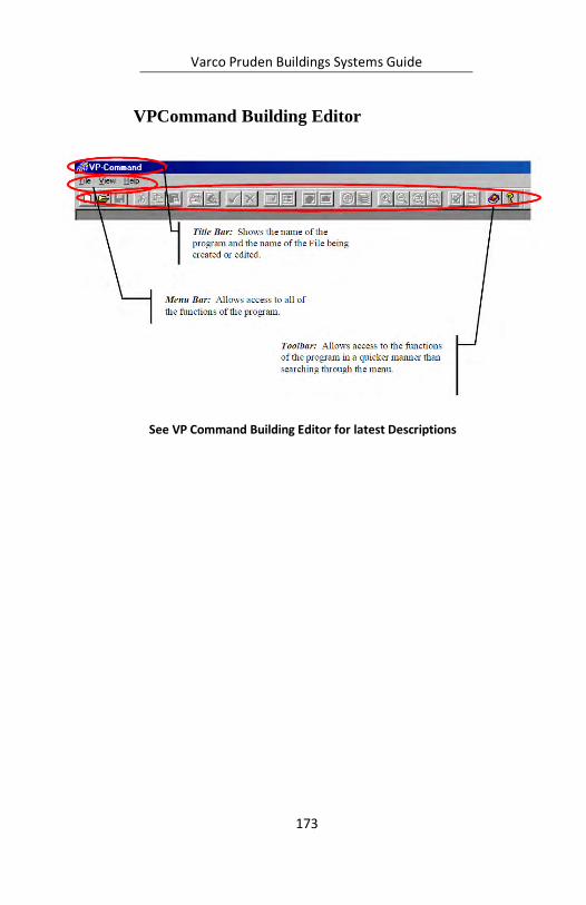
Varco Pruden Buildings Systems Guide
173
VPCommand Building Editor
See VP Command Building Editor for latest Descriptions
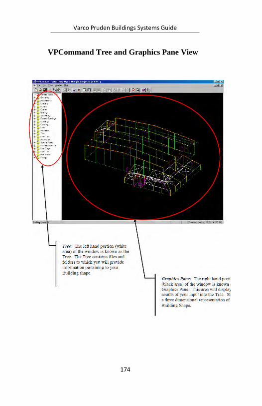
Varco Pruden Buildings Systems Guide
174
VPCommand Tree and Graphics Pane View
Varco Pruden Buildings Systems Guide
175
VPCommand Tree Description
The “Tree” is where is where the majority of the action takes place in VPCommand. The tree is the left-hand portion of the screen within the Building Editor function. The right-hand portion of this screen is called the “Graphics Pane” which we will discuss later in more detail. A “Tree” in the VP Command sense is similar to a real, living tree that has larger branches, and smaller branches extending from the larger branches.
The Tree has a “hierarchical” set of folders for
each available topic. Webster’s dictionary defines a hierarchy as “a system of church government by priests or other clergy in graded ranks”. What does this definition have to do with VPCommand you may ask? Absolutely nothing! Another definition of hierarchy is “a group of persons or things arranged in order of rank, grade, class, etc”.
Think of a hierarchy as an upside-down pyramid,
with the large base containing a majority of information for a topic (for ex., frames, covering, etc.) going down to the tip of the pyramid containing more detailed information for that topic (for ex., the flange thickness of a column, the sheeting direction of panels on a particular wall, etc.). Items listed in the Tree follow this “upside-down flow”. Information contained at one level (consider Covering) applies to ALL folders and/or files within that topic unless changed at a lower level. If changed, information from that point downward within the topic applies.
Let’s think about this hierarchy, files, and folders stuff another way. Consider socks. Yes, I said socks,
Varco Pruden Buildings Systems Guide
176
those things you wear on your feet. Think of your sock drawer as a Folder. Within that drawer-folder are contained your socks. The drawer is the Folder, the socks are the files. Within that main drawer-folder, you may wish to create compartments in the drawer to separate your socks according to color. In this case, the main drawer is a folder called “socks” containing other compartment-folders called “Black Socks” and “White Socks”. The socks in each compartment are the files. If you get really obsessive-compulsive, you can further break down your socks in each compartment according to their fabric, the day of the week in which to wear them, etc.
Now, with this socks stuff in mind, let’s look at it in VPCommand terms. Consider Covering. Covering is the main sock drawer-folder. Within this folder are compartments called “Default Information” and “Data” (White and Black Socks). Within the Default Information and Data folders are additional folders and files (Wool Socks, Tuesday Socks, etc.). Information contained in the Default Information folder is applied to all folders and/or files below, unless changes are made. For example, the Default Information may contain Panel Rib Roof (White Socks). If I move down to my Shape folder and change my roof panel to SSR (Green Socks), the green socks will take precedence for my shape. It will not, however, have any effect at the upper lever folders. If I add green socks to my white sock drawer, it will always contain green socks until I remove them! Thus, my shape will always have SSR until I change it at the shape level. If you make a change in the tree, you have taken ownership of that file and your change will be maintained until YOU modify or delete it!
Continuing our discussion of the Tree and how to work within it, see the following pages to look at the Toolbar and how it changes to allow functions applicable
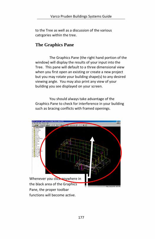
Varco Pruden Buildings Systems Guide
177
to the Tree as well as a discussion of the various catrgories within the tree.
The Graphics Pane
The Graphics Pane (the right hand portion of the window) will display the results of your input into the Tree. This pane will default to a three dimensional view when you first open an existing or create a new project but you may rotate your building shape(s) to any desired viewing angle. You may also print any view of your building you see displayed on your screen.
You should always take advantage of the Graphics Pane to check for interference in your building such as bracing conflicts with framed openings.
Whenever you click anywhere in
the black area of the Graphics
Pane, the proper toolbar
functions will become active.
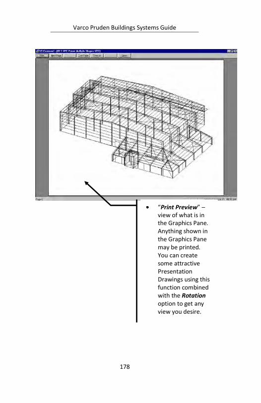
Varco Pruden Buildings Systems Guide
178
“Print Preview” –
view of what is in the Graphics Pane. Anything shown in the Graphics Pane may be printed. You can create some attractive Presentation Drawings using this function combined with the Rotation option to get any view you desire.
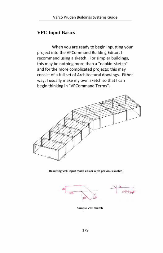
Varco Pruden Buildings Systems Guide
179
VPC Input Basics
When you are ready to begin inputting your project into the VPCommand Building Editor, I recommend using a sketch. For simpler buildings, this may be nothing more than a “napkin-sketch” and for the more complicated projects; this may consist of a full set of Architectural drawings. Either way, I usually make my own sketch so that I can begin thinking in “VPCommand Terms”.
Sample VPC Sketch
Resulting VPC input made easier with previous sketch

Varco Pruden Buildings Systems Guide
180
Every VPCommand project, no matter how complicated, will consist of Geometry (length, width, eave height, roof pitch, etc.) and Frames (types, locations, etc.). All buildings will also have Loads placed on them, panel types, trim conditions, etc. Having good defaults built will save you input time and insure accuracy.
The order in which the “Tree” is laid out makes
for a very logical input order flow. Begin with the General Information section (inputting your Customer’s Information, Jobsite Location, etc.) and following through each level (skipping those in which you do not need to modify information) and finishing up with the Pricing Folder (inputting freight, warranties, special adjustments, etc.). In Lesson 1 (obtained in a Training Session or on the VP University web site) you use techniques that will apply to 99 % of the buildings you will input, from the building’s Basic Geometry through designing your project and running Reports and Drawings.
VPC Defaults
What are “Defaults”?: Think of Default projects as a baseline or beginning point. A Default building contains information that will be applied to the project you create using this default. The intent of Defaults is to save you input time and to insure accuracy for your projects. The less information you have to input, the less chance for error or forgetting items. We will look at each item in the “Tree” of the Building Editor and look at some considerations you should make pertaining to YOUR default projects.
Varco Pruden Buildings Systems Guide
181
What can be Defaulted?: Basically, any information that is not “dimensional” can be defaulted. Items such as Loads and Codes, Panel Information (types, finishes, colors, etc.), trim preferences, etc. can be defaulted. Some Dimensional items such as a 10 x 12 framed opening centered in a bay of a wall cannot be defaulted. The 10 x 12 framed opening can be defaulted, but its location cannot. Building Geometry, as well, cannot be defaulted (length, width, eave height, etc.)
How many Defaults can I have?: You can have as many defaults as you wish. Some users have defaults for all possible roof and wall panel conditions (SSR-PR, PR-PR, SSR-VR, etc.), some have Defaults for various loading conditions in the counties and/or states they work. But the key is to have good defaults that work for you! It is important to name your defaults something you can relate to. I have adopted the method of abbreviating my defaults as follows: 2006 IBC Warren County, Virginia SSR PR EG CR 4r 3w. To me this means, Standing Seam Roof, Panel Rib Walls, Eave Gutter and Downspouts, Crimped Base, 4” and 3” insulation in the roof and walls respectively with 2006 IBC loading in Warren County, Virginia. Use any name designation that makes sense to you.
Updating Defaults: Update your default projects as often as needed. If you find yourself making repetitive changes to a lot of your projects, such as adding 3” VRV insulation, then simply open your default and apply this change. However, if you are using old defaults, you must update these or delete and create new Default projects in order to take advantage of the VP Buildings standard product default conditions. With each new version of VPC, read the included
Varco Pruden Buildings Systems Guide
182
documentation as well as the “Read-Me” file to see what is new.
Varco Pruden Buildings Systems Guide
183
Notes:
Varco Pruden Buildings Systems Guide
184
Description of VPCommand (VPC) Colors
Frames: Red Frames indicates that the frame designed and detailed completely.
Frames: Yellow indicates that the frame has not been designed or Interactive Design is required. This member has not priced.
Secondary: Cyan (Light Blue) Secondary indicates the secondary has designed and detailed.
Secondary: White Secondary indicates that the secondary has not been designed or that design has failed for that member. This member has not priced.
Bracing: Yellow Bracing indicates that the bracing member has been designed and detailed.
Bracing: White Bracing indicates that the bracing member has not been designed or that design has failed for that member. This member has not priced.
Trim: Salmon (Pink) Trim indicates that a trim segment has generated. You must verify on the Reports if there are any unpriced trim items.
Trim: Red-Dashed Lines indicate that the trim segment has not been generated.
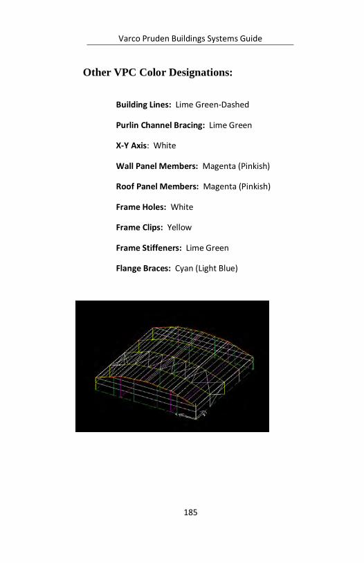
Varco Pruden Buildings Systems Guide
185
Other VPC Color Designations:
Building Lines: Lime Green-Dashed
Purlin Channel Bracing: Lime Green
X-Y Axis: White
Wall Panel Members: Magenta (Pinkish)
Roof Panel Members: Magenta (Pinkish)
Frame Holes: White
Frame Clips: Yellow
Frame Stiffeners: Lime Green
Flange Braces: Cyan (Light Blue)

Varco Pruden Buildings Systems Guide
186
Reviewing Drawings and Details
In your never-ending quest to make certain that you receive the parts and pieces you believe you are inputting into VPCommand, following are some recommendations. This is the minimum items I complete on any VPC file I input.
1. Thoroughly review Input Report. 2. Complete and Save VPC-Run (Run / Run All)
function 3. Visually Review the resulting “Colors” in the
Graphics Pane in the Building Editor. See VPC-Tip #2 on the VP University website for more information on this.
4. Run and Review Pricing and Edit Check Reports. Look for the asterisks (*), and address as necessary. Generating a Pricing will prompt you to review the Engineering Content.
5. When I feel I am getting what I need, I generate some Drawings and the Standard Erection
Prior to VPC-Run

Varco Pruden Buildings Systems Guide
187
Details SEDs) to review (you can view these on screen or print out if you desire). If my SEDs show Panel Rib roof details, and I thought I input SSR, chances are that my Input is not correct. A common mistake is to have SSR on the main roof, and then I input a canopy and forgot to set this up in my Default accordingly or forgot to change it during input.
How To Use the Engineering Content Screen Follow these steps:
Open the pricing folder and double click the Engineering Content to review the conditions.

Varco Pruden Buildings Systems Guide
188
Revised: Show the status of the condition. If the condition was added by the system it will show No, in that the status of that item was set but has not been changed by the user. If the user has modified a system generated or user input item the status will show Yes.
System: Shows the quantity of system detected conditions.
User: Shows the quantity of user input conditions.
Generate: Shows the type of condition, either System or User. A system condition should be detected by VP Command automatically. A user condition must be entered by the user.
Category: Shows the category of input the condition is in. JPU stands for Job Processing Units used internally by Varco Pruden.
Description: Shows a brief description of the condition.
Engineering Content Screen (See VPCommand for latest screen)
Varco Pruden Buildings Systems Guide
189
All system generated quantities should be
verified by the user before final pricing. Any quantities that are incorrect may be overridden by typing the correct quantity in the user quantity field. To type a quantity, simply click in the desired field and type the number.
When all user changes are complete you can
click the Lock Current Values check box so that the engineering content values will not change if the job is re-run. This should only be used when the pricing is finalized.
Once all input is complete click OK and save the
project.
Engineering Content Charges
Each point added in the engineering content list is worth $100 engineering fee. An itemized break down of conditions and points is shown at the end of the pricing report. There is also a new category on the pricing summary to show the net engineering fee added.
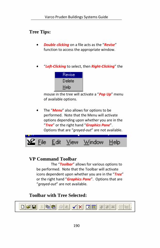
Varco Pruden Buildings Systems Guide
190
Tree Tips:
Double clicking on a file acts as the “Revise” function to access the appropriate window.
“Left-Clicking to select, then Right-Clicking” the
mouse in the tree will activate a “Pop Up” menu of available options.
The “Menu” also allows for options to be performed. Note that the Menu will activate options depending upon whether you are in the “Tree” or the right hand “Graphics Pane”. Options that are “grayed-out” are not available.
VP Command Toolbar The “Toolbar” allows for various options to
be performed. Note that the Toolbar will activate icons dependent upon whether you are in the “Tree” or the right hand “Graphics Pane”. Options that are “grayed-out” are not available.
Toolbar with Tree Selected:
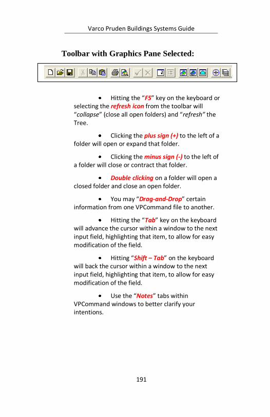
Varco Pruden Buildings Systems Guide
191
Toolbar with Graphics Pane Selected:
Hitting the “F5” key on the keyboard or selecting the refresh icon from the toolbar will “collapse” (close all open folders) and “refresh” the Tree.
Clicking the plus sign (+) to the left of a folder will open or expand that folder.
Clicking the minus sign (-) to the left of a folder will close or contract that folder.
Double clicking on a folder will open a closed folder and close an open folder.
You may “Drag-and-Drop” certain information from one VPCommand file to another.
Hitting the “Tab” key on the keyboard will advance the cursor within a window to the next input field, highlighting that item, to allow for easy modification of the field.
Hitting “Shift – Tab” on the keyboard will back the cursor within a window to the next input field, highlighting that item, to allow for easy modification of the field.
Use the “Notes” tabs within VPCommand windows to better clarify your intentions.
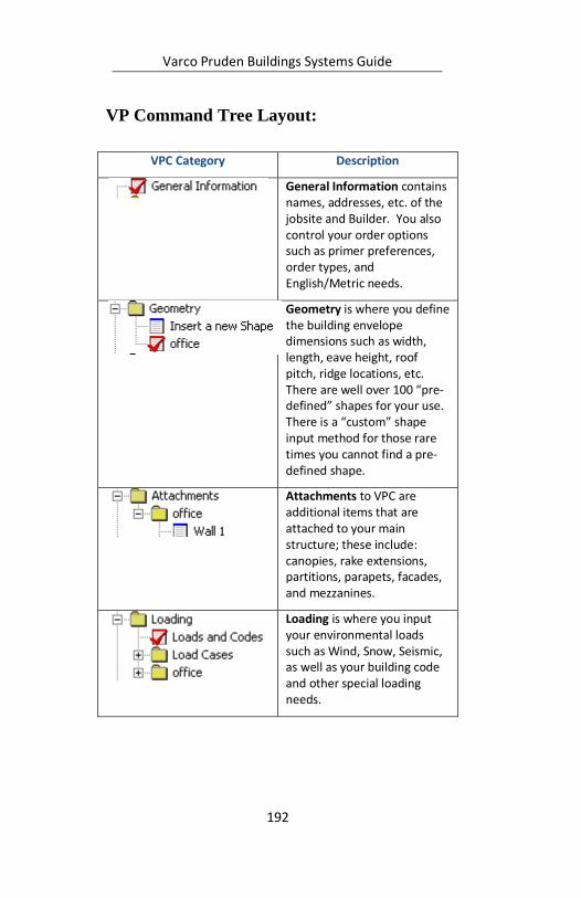
Varco Pruden Buildings Systems Guide
192
VP Command Tree Layout:
VPC Category Description
General Information contains names, addresses, etc. of the jobsite and Builder. You also control your order options such as primer preferences, order types, and English/Metric needs.
Geometry is where you define the building envelope dimensions such as width, length, eave height, roof pitch, ridge locations, etc. There are well over 100 “pre-defined” shapes for your use. There is a “custom” shape input method for those rare times you cannot find a pre-defined shape.
Attachments to VPC are additional items that are attached to your main structure; these include: canopies, rake extensions, partitions, parapets, facades, and mezzanines.
Loading is where you input your environmental loads such as Wind, Snow, Seismic, as well as your building code and other special loading needs.
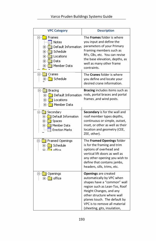
Varco Pruden Buildings Systems Guide
193
VPC Category Description
The Frames folder is where you input and define the parameters of your Primary Framing members such as RFs, CBs, etc. You can revise the base elevation, depths, as well as many other frame contraints.
The Cranes folder is where you define and locate your desired crane information.
Bracing includes items such as rods, portal braces and portal frames ,and wind posts.
Secondary is for the wall and roof member types depths, continuous or simple, outset, inset, or other as well as their location and geometry (CEE, ZEE, other).
The Framed Openings folder is for the framing and trim options of overhead and vertical lift doors as well as any other opening you wish to define that contains jambs, headers, sills, trims, etc.
Openings are created automatically by VPC when shapes have a “common” wall region such as Lean-Tos, Roof Height Changes, and any other structure where wall planes touch. The default by VPC is to remove all material (sheeting, gits, insulation,
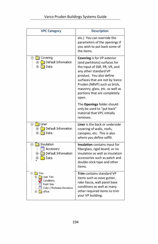
Varco Pruden Buildings Systems Guide
194
VPC Category Description
etc.) You can override the parameters of the openings if you wish to put back some of the items.
Covering is for VP exterior (and partitions) surfaces for the input of SSR, PR, VR, and any other standard VP product. You also define surfaces that are not by Varco Pruden (NBVP) such as brick, masonry, glass, etc. as well as portions that are completely open.
The Openings folder should only be used to “put back” material that VPC initially removes.
Liner is the back or underside covering of walls, roofs, canopies, etc. This is also where you define soffit.
Insulation contains input for fiberglass, rigid board, or no insulation as well as insulation accessories such as patch and double-stick tape and other items.
Trim contains standard VP items such as eave gutter, rake fascia, wall panel base conditions as well as many other required items to trim your VP building.
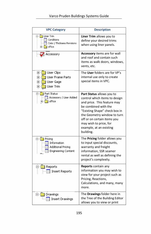
Varco Pruden Buildings Systems Guide
195
VPC Category Description
Liner Trim allows you to define your desired trims when using liner panels.
Accessory items are for wall and roof and contain such items as walk doors, windows, vents, etc.
The User folders are for VP’s internal use only to create special items in VPC.
Part Status allows you to control which items to design and price. This feature may be combined with the “Existing Shape” check box in the Geometry window to turn off or on certain items you may wish to price, for example, at an existing building.
The Pricing folder allows you to input special discounts, warranty and freight information, SSR seamer rental as well as defining the project’s complexity.
Reports contain any information you may wish to view for your project such as Pricing, Reactions, Calculations, and many, many more.
The Drawings folder here in the Tree of the Building Editor allows you to view or print
Varco Pruden Buildings Systems Guide
196
VPC Category Description
only various erection drawings. It is recommended that you use the separate “Drawings Editor” if you wish to modify drawings. There you can create dxf, dwg, as well as 3D models, and add text, lines, details, etc.

Varco Pruden Buildings Systems Guide
197
Notes:
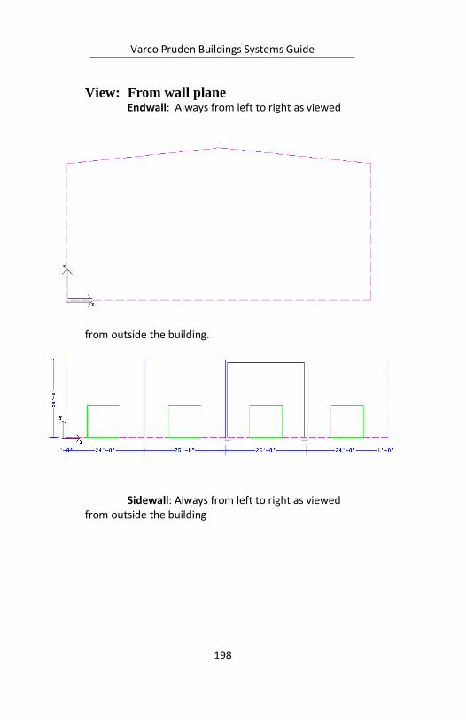
Varco Pruden Buildings Systems Guide
198
View: From wall plane Endwall: Always from left to right as viewed
from outside the building.
Sidewall: Always from left to right as viewed from outside the building
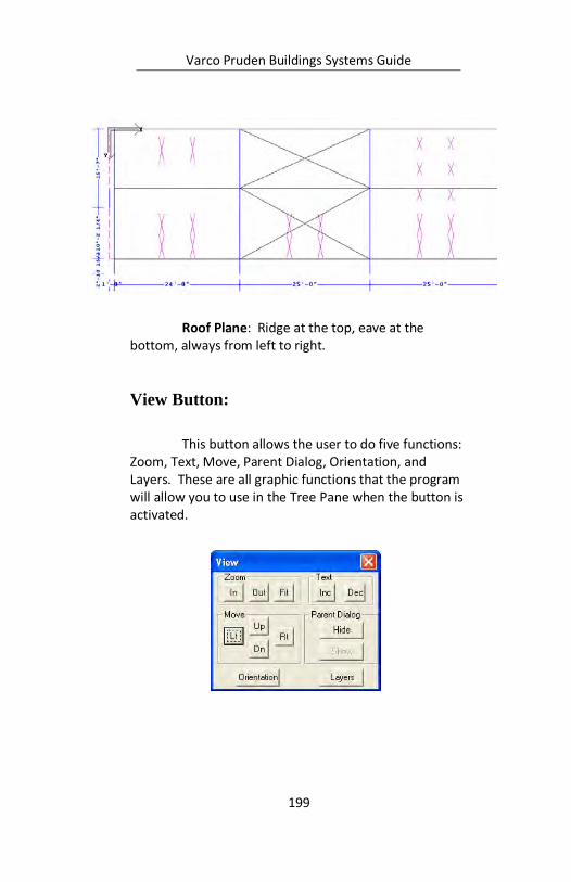
Varco Pruden Buildings Systems Guide
199
Roof Plane: Ridge at the top, eave at the bottom, always from left to right.
View Button:
This button allows the user to do five functions: Zoom, Text, Move, Parent Dialog, Orientation, and Layers. These are all graphic functions that the program will allow you to use in the Tree Pane when the button is activated.
Eave
Ridge

Varco Pruden Buildings Systems Guide
200
Parent Dialog will allow you to hide or show the screen you are working on so that you can see more of the graphics pane.
Section: From-To Reference Points The “From” eave height is represented by a
“Green” section arrow, and the “To” eave height is represented by a “Red” arrow. Note that for some pre-defined shapes the “Green-From” arrow is absent. The “Green-From” arrow is then taken to be opposite the “Red-To” arrow.
The more complicated shapes will clearly show both the red and green arrows.
The Section can also be referenced as standard architectural sections with the “Left” arrow being “From” and the “Right” arrow being “To”.
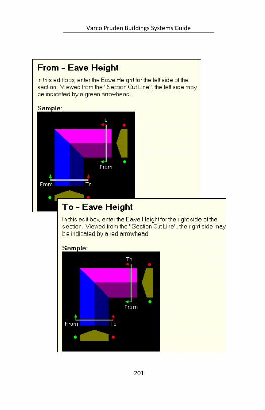
Varco Pruden Buildings Systems Guide
201
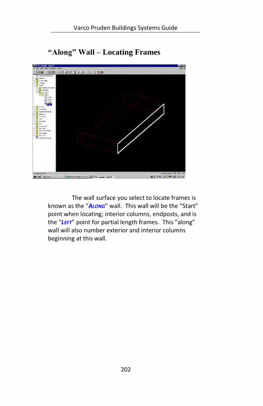
Varco Pruden Buildings Systems Guide
202
“Along” Wall – Locating Frames
The wall surface you select to locate frames is known as the “ALONG” wall. This wall will be the “Start” point when locating; interior columns, endposts, and is the “LEFT” point for partial length frames. This “along” wall will also number exterior and interior columns beginning at this wall.
“ALONG” wall highlights in the Graphics Pane when selected from the tree.
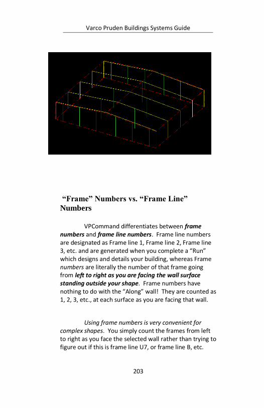
Varco Pruden Buildings Systems Guide
203
“Frame” Numbers vs. “Frame Line”
Numbers
VPCommand differentiates between frame numbers and frame line numbers. Frame line numbers are designated as Frame line 1, Frame line 2, Frame line 3, etc. and are generated when you complete a “Run” which designs and details your building, whereas Frame numbers are literally the number of that frame going from left to right as you are facing the wall surface standing outside your shape. Frame numbers have nothing to do with the “Along” wall! They are counted as 1, 2, 3, etc., at each surface as you are facing that wall.
Using frame numbers is very convenient for complex shapes. You simply count the frames from left to right as you face the selected wall rather than trying to figure out if this is frame line U7, or frame line B, etc.

Varco Pruden Buildings Systems Guide
204
Varco Pruden Buildings Systems Guide
205
Notes:
Varco Pruden Buildings Systems Guide
206
VPCommand Parts Status
The VP Command Parts Status section can be used to control which parts and pieces you wish to price. For example, you can use this to remove material at existing building conditions. There may be times you wish to leave some items to design, detail, and price for existing buildings such at a wall that is higher than the new shape. You can leave the required secondary, trim, etc. to “run” and use for the existing building.
In the geometry section of VPC there is a check box for “existing shape.” You may use this to specify the entire shape as existing and thereby “turning off” all items (pertaining to the existing shape) at the Parts Status level.
VPCommand Drawings
In the VPC Building Editor there is a folder for “Drawings.” In this level you can view and print Drawings. When you create drawings they are “as designed” at that time; if you revise anything within VPC any created drawings are not updated, your must create new ones.
The “VPC Drawings Editor” offers more flexibility and options concerning drawings. At the function you can create, plot, revise, etc. your drawings. You can create “dxf” and “dwg” files as well as three-dimensional models to use in your other drawing applications.
See the “Help” section within the drawing editor for additional information.
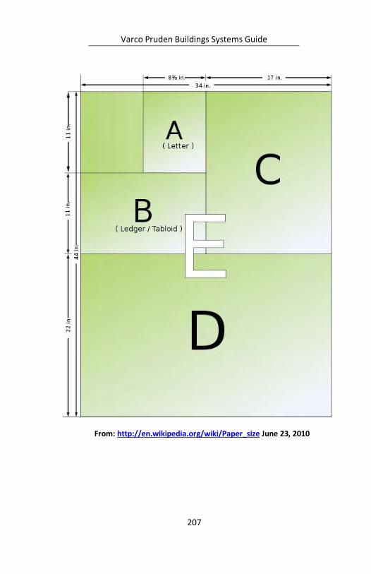
Varco Pruden Buildings Systems Guide
207
From: http://en.wikipedia.org/wiki/Paper_size June 23, 2010
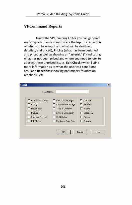
Varco Pruden Buildings Systems Guide
208
VPCommand Reports
Inside the VPC Building Editor you can generate many reports. Some common are the Input (a reflection of what you have input and what will be designed, detailed, and priced), Pricing (what has been designed and priced as well as showing an “asterisk” (*) indicating what has not been priced and where you need to look to address these unpriced issues, Edit Check (which listing more information as to what the unpriced conditions are), and Reactions (showing preliminary foundation reactions), etc.

Varco Pruden Buildings Systems Guide
209
Notes:
Varco Pruden Buildings Systems Guide
210
Order Entry System
The VP Order Entry System (OE) is a live web portal that provides a quick and efficient means of transferring VP Command Building Estimates and Building Orders between your office and VP Buildings. In addition, it offers direct access to many other valuable resources offered by VP Buildings.
Transfer VP Command files back and forth to VP Estimating
Transfer Building Orders to VP
Attach Order/Estimate Clarification Forms (OCFs) as well as any other email-able documents such as digital photos, drawings (pdf, please), and any MS Office format files. For instructions, log onto the Order Entry System, click on Help, then Online Help, and go to the Order Entry How-tos in the lefthand column for website or login assistance, just call VP Software Support at 877-874-3579.
The Tool Bar on the Help Screen (Help / Online
Help) contains links to important additional VP Related Web tools. Some of the most common are:
VPU - VP University Course descriptions, Updated schedules, and
Registration Forms, VP Command Tips - Short reviews addressing over 50 (and growing) common VP Command issues.
VPCommand Lessons - All VPC Lessons from Level I, and II classes for you to review.
Varco Pruden Buildings Systems Guide
211
Downloadable VP Product Seminar modules for your use
Lots of other material…
Supplemental Price Book This Online manual contains all of the tools,
guidelines, policies, definitions, and terms and conditions applicable to your everyday dealings with VP Buildings that are not addressed on VP Command. Here you'll also find:
Quote Assistance Request Forms (VP Command estimate assistance cover sheet)
Quote Request Form (attach to drawings for Complete Estimates)
Order Clarification Forms Standard questions and forms for specific conditions
Seamer Rental / Purchase costs and rental period definition
Warranty Information
Owners' Preventative Maintenance Manual
Phone numbers and addresses for Service Center personnel as well as Sales contacts
Freight Calculator to determine real-time current freight costs (subject to escalation)
and lots more
VP.Com Direct access to VP's public website
VP Marketing This website provides access to many tools
which will help you become more successful. Marketing Tools such as Literature, Direct Mail, Coop advertising, and Yellow Pages Ready to use press release templates, print ads, and VP Logos, VP Builder Hall of Fame Contest and Image Archive for your use, Economic and Market
Varco Pruden Buildings Systems Guide
212
Information for your assigned Trade Area, Updates from Varco Pruden Marketing, Systems, and R&D Departments. Also available at: www.vpmarketinginfo.com.
VP Components Online pricing and ordering of components only.
Great typical details! Also available at: www.vpcomp.com.
VP Builder Site The www.vpbuilder.com site is for accessing the latest schedule of training sessions as well as to obtain pre-class material.
VARCO PRUDEN ROOF SYSTEMS 7
VP Roofing
Retrofit and Re-roof Solutions Building owners looking for a way to stop roof
leaks, reduce maintenance cost and improve the
appearance of their facility are finding the answer with VP Roof Systems and their local Varco Pruden Builder.
Whether your current roof is a non-metal or a metal roof…flat or sloped, Varco Pruden Roof Systems can
provide a solution that gives you long-term, weather-tight protection and fewer roofing headaches.
7
http://www.vp.com/Products/ProductDescriptions/VPRo
ofSystems.aspx February 18, 2010

Varco Pruden Buildings Systems Guide
213
Benefits of a Varco Pruden Retrofit or Re-roof solution include:
A roof system designed to meet the highest
industry standards for quality and performance
A selection of panel options and
architecturally attractive colors
The option of adding slope to flat roofs, eliminating "ponding" and problems related to standing water
Increased energy-efficiency with additional
insulation and "cool paint" formulations
Products from Varco
Pruden Roof Systems include:
(A) Built Up Slope Structural - Ideal for
applications when a project requires positive roof drainage to prevent water from standing on
C
Varco Pruden Buildings Systems Guide
214
the roof surface. A built- up slope also allows for additional insulation, improving energy-efficiency and reducing heating and cooling costs. All structural materials are made from durable, galvanized steel, can be installed over the current structure without interrupting on-going business operations are designed and manufactured to give years of trouble-free service.
(B) SLR Roof Sheeting - An architectural roof panel designed to give improved aesthetics while providing long-term
weather-tight performance. Made from sturdy 24 or 22 gauge galvalume steel and coated with highest quality kynar/hylar paint finishes, SLR panels meet the highest industry standards for roof sheeting. Optional, cool
color paints can provide additional thermal efficiency and help reduce "heat-island" effects.

Varco Pruden Buildings Systems Guide
215
(C)SSR Roof Sheeting - Varco Pruden’s most recognized roof solution, this engineered panel is ideal for low-slope applications as low as ¼’:12. The 3" tall ribs are field seamed to provide a sealed membrane surface that stands up to the toughest weather challenges. SSR’s patented seamed ridge cap provides additional weather protection and VP’s unique sliding clip allows the roof to respond
to thermal changes and reduce panel wear Each Varco Pruden Roof System project combines the advantages of superior roof engineering and design with warranted, proven products. Your local Varco Pruden is your local
source for complete information and assistance with your project needs. To find out more about Varco
Pruden Roof Systems and to get in touch with your local contact, send your request to

Varco Pruden Buildings Systems Guide
217
Fast Track (as of February 2010. See Fast Track input for
current options)
Fast Track Loads: Standard building use, collaterals, snow, wind & seismic, Max Wind, 140 MPH Max Snow, 100 PSF Geometry: Width: 20’ to 250’ wide Length: 30’ to 750’ Eave Heights: 10’ to 30’ Roof Pitches: 1/4 to 6:12 pitch Single Sloped: max high eave 35’ Gable Buildings: both symmetrical & unsymmetrical Note: The ridge can be offset up to 20% of the building width from the center.
Fast Track Frames: Rigid Frames 20’ to 120’ CB-1, 80’ to 140’ CB-2, 120’ to 210’ CB-3, 160’ to 250’ CB-4, 200’ to 250’ CB-5, 240’ to 250’ Base of columns can be adjusted Note: Tapered exterior columns only and the interior columns are equally spaced. Endframes: Single Zee, 20’ to 250’, 1, 2, 3 & 4:12 even pitches only Post & Beam Rigid Frames w/endposts, 20’ to 120’ Rigid Frames, full load, w/endposts 20’ to 120’ Standard & special endpost spacings Bays: Mixed is allowed, 15’ to 32’ Note: There is a max. variance in bay width of ±30%

Varco Pruden Buildings Systems Guide
218
Fast Track Bracing: Panel diaphragm considered before adding diagonals Wall Rods Must use Rod Bracing option available Portal Braces up to code maximum Portal Frames
Fast Track Current Available Building
Codes 1997 Uniform Building Code 1999 National Building Code (BOCA) 1999 Standard Building Code 2000 IBC with 2003 DC Supplement 2000 International Building Code 2002 Kentucky State Building Code with 2003 Supplement 2002 NYS Building Code 2002 Wisconsin State Building Code 2003 Indiana Building Code 2003 International Building Code 2003 Minnesota State Building Code 2003 Virginia Uniform Statewide Building Code 2004 Florida Building Code with 2005 Supplement 2004 Florida State Building Code 2005 Connecticut Building Code 2005 National Building Code of Canada 2005 North Dakota 2005 Ohio Building Code 2005 Vermont Building Code 2006 Georgia State Amendments 2006 International Building Code 2006 North Carolina State Building Code 6
th Edition Massachusetts
7th Edition Massachusetts 2007 Florida State Building Code 2007 Minnesota State Building Code
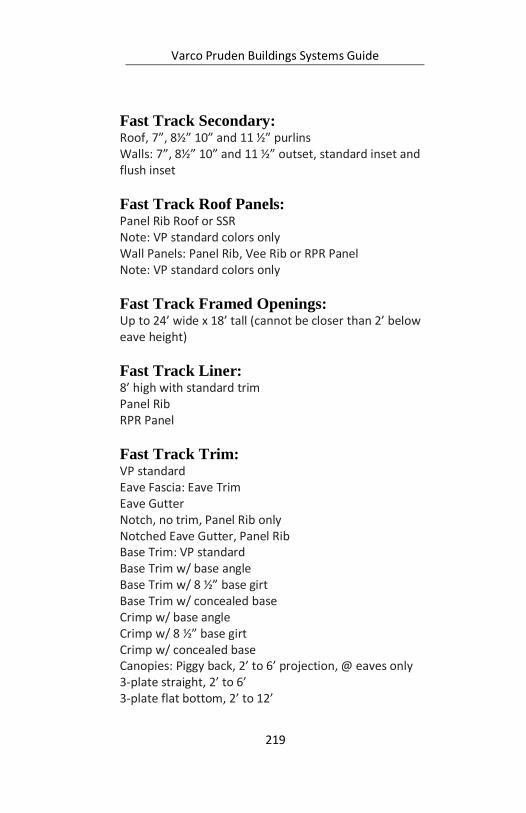
Varco Pruden Buildings Systems Guide
219
Current Available Building Codes
Fast Track Secondary: Roof, 7”, 8½” 10” and 11 ½” purlins Walls: 7”, 8½” 10” and 11 ½” outset, standard inset and flush inset
Fast Track Roof Panels: Panel Rib Roof or SSR Note: VP standard colors only Wall Panels: Panel Rib, Vee Rib or RPR Panel Note: VP standard colors only
Fast Track Framed Openings: Up to 24’ wide x 18’ tall (cannot be closer than 2’ below eave height)
Fast Track Liner: 8’ high with standard trim Panel Rib RPR Panel
Fast Track Trim: VP standard Eave Fascia: Eave Trim Eave Gutter Notch, no trim, Panel Rib only Notched Eave Gutter, Panel Rib Base Trim: VP standard Base Trim w/ base angle Base Trim w/ 8 ½” base girt Base Trim w/ concealed base Crimp w/ base angle Crimp w/ 8 ½” base girt Crimp w/ concealed base Canopies: Piggy back, 2’ to 6’ projection, @ eaves only 3-plate straight, 2’ to 6’ 3-plate flat bottom, 2’ to 12’
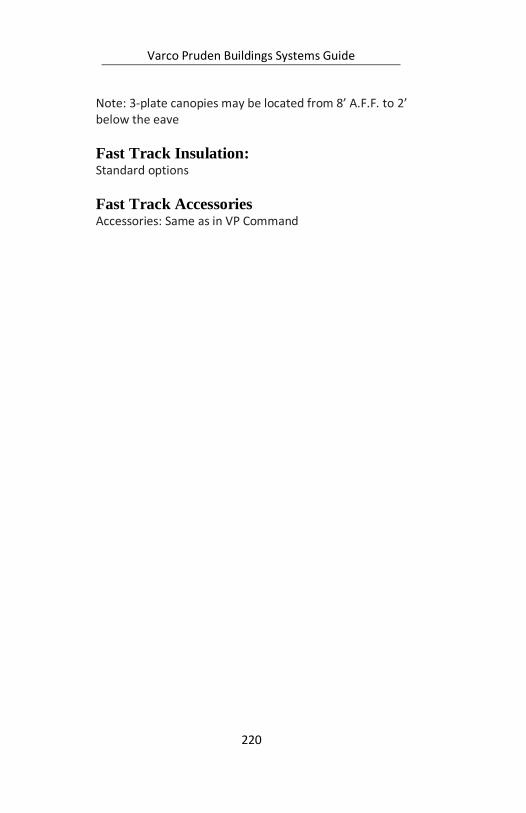
Varco Pruden Buildings Systems Guide
220
Note: 3-plate canopies may be located from 8’ A.F.F. to 2’ below the eave
Fast Track Insulation: Standard options
Fast Track Accessories Accessories: Same as in VP Command

Varco Pruden Buildings Systems Guide
221
Notes:

Varco Pruden Buildings Systems Guide
222
How to Price a VP Building8
Five Pricing Methods
There are two methods you can use to fully estimate a
VP Building in your office.
1. - For simple buildings, we provide the VP Fast Track
pricing system, accessible online, within Order Entry.
2. - For other buildings, you should utilize VP's
proprietary VP Command software leased by your firm.
Based upon your level of expertise, you may be able to
model many varied structures onto VP Command in your
office. Running the building file you have created in your
office, you will be able to generate estimates, preliminary
drawings and preliminary engineering data.
The final three methods involve the partial or complete
involvement of VP's Estimating Group.
3. - The third method is a shared effort, initiated by you,
the builder, inputting the project into VP Command in
your office and then transmitting the file to VP
Estimating for assistance in completing the quote. This
method is the most frequently used of the five shown
here and requires you to fax or e-mail the VPC Quote
8 By Dave Cleary
Varco Pruden Buildings Systems Guide
223
Request form, along with the OCF Standard Questions
forms.
4. - Sometimes a design/build project is complex and
modeling the project onto VP Command is simply beyond
your level of expertise. In this case, we ask you to send
sketches, drawings, VP's Price Confirmation request
sheets along with the OCF Standard Questions form to
VP Estimating. VP Estimating can complete quotations
for complex design/build projects. We will work closely
together with you and your team using our best value-
engineering skills to generate a complete estimate.
5. - If a design professional has prepared Plans and
Specifications for a project which clearly shows all of the
environmental loads, building geometry, and other
parameters required for the project, VP Estimating can
complete the estimate. As in method 4, we ask that you
send the VP Price Confirmation request sheets and the
OCF Standard Questions form with the drawings and
specifications.
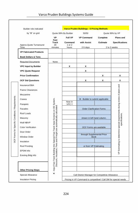
Varco Pruden Buildings Systems Guide
224
Builder role indicated
Varco Pruden Buildings - 5 Pricing Methods
by "X" on grid Quote 99% By Builder 50/50 Quote 99% by VP
VP Full VP VP Command Complete Plans and
Fast Track Command with Assist Estimate Specifications
Approx.Quote Turnaround Time
30 minutes
1 or 2 hours 2-5 days 2 to 3 weeks
VP Fabricated Products
Book Dollars & Tons
Required Documents None
VPC Input by Builder
X -
In
pu
t F
ast
Tra
ck B
uild
ing
In
to S
pe
cia
l F
ast
Tra
ck I
np
ut
Scre
ens o
n O
E S
yste
m.
Dis
co
un
t, I
nsu
latio
n,
Fe
es a
nd
Fre
igh
t a
re a
uto
ma
tica
lly c
alc
ula
ted
.
X X
VPC Quote Request X
Price Confirmation X X
OCF Std Questions X X X
OC
F F
orm
s f
or
Sp
ecific
Co
nditio
ns /
Re
quir
em
en
ts
Insurance/SBA
VP
Estim
atin
g t
o d
ete
rmin
e s
pe
cia
l re
quir
em
en
ts d
uri
ng
re
vie
w o
f pla
ns a
nd
sp
ecific
atio
ns.
Frame Clearances
Mezzanine
Cranes X - Builder to submit applicable
Parapets Now in VPC !!
Facades Order Clarification Forms
Roof Loads
Masonry shown in left hand column.
Wall NBVP
Color Verification OCF Forms are available
Door Order
Window Order through Supplemental Price
Book
Insulation
Roof Ponding or from VP Estimating.
EPDM Info
Existing Bldg Info
Other Pricing Steps
Special Allowance Call District Manager for Competitive Allowance
Insulation Pricing Pricing in VP Command is competitive!! Call DM for special needs.
Freight Estimate X X Calculated by VP Estimating
Bar Joists Priced by VP Estimating
Decking Priced by VP Estimating
Seamer Rental X - Purchase Seamer or add Rental Charges per SPB
Engineering Fees X X Calculated by VP Estimating
Drawing Fees
X - Calculated by VPC based upon Order Type and Document Request
Taxes or Exemption Cert. X X X X X

Varco Pruden Buildings Systems Guide
225
Notes:
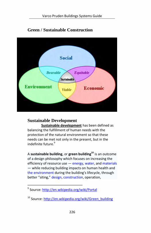
Varco Pruden Buildings Systems Guide
226
Green / Sustainable Construction
Sustainable Development Sustainable development has been defined as
balancing the fulfillment of human needs with the protection of the natural environment so that these needs can be met not only in the present, but in the indefinite future.9
A sustainable building, or green building10 is an outcome of a design philosophy which focuses on increasing the efficiency of resource use — energy, water, and materials — while reducing building impacts on human health and the environment during the building's lifecycle, through better “siting,” design, construction, operation,
9 Source: http://en.wikipedia.org/wiki/Portal
10 Source: http://en.wikipedia.org/wiki/Green_building
Varco Pruden Buildings Systems Guide
227
maintenance, and removal. Though green building is interpreted in many different ways, a common view is that they should be designed and operated to reduce the overall impact of the built environment on human health and the natural environment by:
Efficiently using energy, water, and other resources
Protecting occupant health and improving employee productivity
Reducing waste, pollution and environmental degradation
USGBC The U.S. Green Building Council (USGBC) defines
green building as “…those that incorporate design and construction practices that significantly reduce or eliminate the negative impact of buildings on the environment and occupants in five broad areas
11”:
1. Sustainable site planning
2. Safeguarding water and water efficiency
3. Energy efficiency and renewable energy
4. Conservation of materials and resources
5. Indoor environmental quality
LEED expands this definition to include “Innovation of Design” or “Innovation in Operations” to include items that go above and beyond the basic green building principles such as: green educational programs; green cleaning; green power purchasing; construction waste
11 Source: Yudelson, Jerry. Green Building A to Z. New
Society Publishers. 2007. Canada.
Varco Pruden Buildings Systems Guide
228
management; etc. Having a LEED certified professional on your project can help you immensely in achieving the desired certifications.
LEED v3.0 credit categories and their point distribution are:
Sustainable Sites (SS) – 12 points
Water Efficiency (WE) – 10 points
Energy & Atmosphere (EA) – 30 points
Material & Resources (MR) – 14 points
Indoor Environmental Quality EG) – 19 points
Innovation in Operations (IO) – 7 points
In order to design a building that can be certified as a green building under LEED (Leadership in Energy and Environmental Design) several factors/activities must be incorporated into the design. Those factors and activities are listed below:
Sustainable Sites
Building should not be developed on prime farmland, land located near the 100-year flood plain, land located within 100 feet of a wetland, or on existing public parkland. Building should be developed, preferably, within existing urban areas to preserve green spaces and reduce urban sprawl. Ideally, the building should be developed on cleaned up and rehabilitated brown-fields.
Orient the building to reduce heat loss in the winter and heat gain in the summer. Use plantings to block wind and direct sunlight.

Varco Pruden Buildings Systems Guide
229
Site disturbance should be kept to a minimum. Buildings with small footprints are preferred.
Maintain existing vegetation located more than 40 feet from the building or 5 feet from roadways and walkways. If the site was previously developed, minimize paving and add green areas on the building site.
Minimize storm water runoff. Provide a means to filter the runoff through plants and settling basins before it is discharged to sewer.
Reduce outdoor light pollution by specifying shields on outdoor lighting.
Water Efficiency
Specify natural landscaping that requires little to no artificial irrigation. If irrigation is required, specify drip irrigation.
Reduce domestic water use by specifying water conserving toilets, urinals, and showers.
Capture and use rainwater for irrigation, makeup to cooling towers, and washing cars.
If local building codes permit, consider using rainwater to flush toilets.
Energy and Atmosphere
Have the building commissioned by a designated Commissioning Authority.
Varco Pruden Buildings Systems Guide
230
Energy performance of the building must meet or exceed the American Society of Heating, Refrigerating, and Air Conditioning Engineers (ASHRAE) Standard 90.12.
No chlorofluorocarbon (CFC) containing equipment permitted in the building.
When practical, use renewable energy resources like solar, wind, and biomass
12.
Reduce or eliminate the use of hydrochlorofluorocarbon (HCFC) containing equipment.
Provide a means to measure ongoing energy and water consumption.
When practical, buy electric power from a green power provider (wind farm).
Indoor Environmental Quality
Building design must comply with ASHRAE Standard 623 and ASHRAE Standard 554.
No smoking in the building.
Carbon dioxide can be monitored to measure ventilation effectiveness.
12 Biomass, a renewable energy, is biological material
derived from living, or recently living organisms, such as
wood, waste, and alcohol fuels
Varco Pruden Buildings Systems Guide
231
Design must insure good ventilation effectiveness.
Contractor must develop and follow an indoor air quality management plan during construction.
Specify building materials that emit little to no volatile organic compounds (VOC).
Indoor chemical pollution sources must be isolated and their emissions exhausted.
Building occupants should have a high degree of control over their environment including views/daylight from outdoors.
Materials and Resources
An area in the building must be designated for the storage and collection of recyclables.
It is preferred to reuse materials from existing buildings.
Recycle 50 to 75% of the construction waste.
When practical, specify salvaged material.
Specify materials with recycled content.
Specify materials that are located within 500 miles of the site.
Specify rapidly renewable materials like bamboo, pine, and wheat grass.
Use only wood grown on tree farms that use certified practices.
Varco Pruden Buildings Systems Guide
232

Varco Pruden Buildings Systems Guide
233
Notes:

Varco Pruden Buildings Systems Guide
234
Notes:
Varco Pruden Buildings Systems Guide
235
Conclusion This manual is designed to assist you in
becoming an expert on the many ways to approach a project. Two things to remember when designing and estimating a project are:
1. Find out the customer’s specific needs on a
project. 2. Apply the products in a creative way to
achieve the project’s objectives. By identifying your customer’s wants and needs,
you will understand the true project goals, which will create a unique advantage over your competition. This edge can win you the project.
Another purpose of this manual is to give tips on
how to determine a project’s needs before you pitch the project to the owner. First, you must discuss the product applications with the owner or specifier in order to determine what and how the VP products will be used.
The more questions that are asked and
answered on the front-end will determine how the project proposal is structured. The VP Buildings’ product line is one of the most versatile in the industry and can be adapted to suit the project’s specific needs.
We hope that this manual is a useful tool for our
Builders in the process of selling, designing and estimating projects. If you have any questions concerning any applications in this manual, please contact your VP Service Center. With your customer-focused proposal and VP’s superior performance, we can create The Ultimate Building Solution for your customer.
Varco Pruden Buildings Systems Guide
236
Disclaimer: The examples and illustrations in this manual
are intended to support the discussion topic and in some cases may not be accurate for a condition being considered. They are generally true, but can always be found to not cover some given situation. They have been developed with particular loadings, dimensions, and codes, and are accurate for the situation intended. The charts showing percentages are meant to be approximate or to show the trend of the subject rather than an exact number for all.
With the many variables in construction: loading; geometry; customer preference; etc. it is often difficult to state that “If A is done, then B will result.” Therefore you should take advantage of the power of VPCommand to create varying building project scenarios for your customer.

Varco Pruden Buildings Systems Guide
237
Notes:

Varco Pruden Buildings Systems Guide
238
Notes:

Varco Pruden Buildings Systems Guide
239
Notes:

Varco Pruden Buildings Systems Guide
240
Notes:
Varco Pruden Buildings Systems Guide
241
Index
(NIA) 404
Insulation ........ 133
“ALONG” wall
frame locations
.............202, 203
“Frame Line”
Numbers
VPC ................. 203
“Frame” Numbers
VPC ................. 203
“LEFT” point
frames ............. 202
10”
Secondary ....... 105
10-year wind ......... 47
11 ½”
Secondary . 74, 105
50-year wind ......... 47
7”
Secondary .. 46, 74,
105, 113, 134
8 ½”
Secondary 105, 219
accessories ... 87, 138,
160
Accessories
Fast Track ........ 220
Accessory .... 154, 160
VPC Tree ........ 195
Additional Weights52
Alternate Span Live
loading .............. 48
angle
Bracing 96, 99, 105,
113, 219
ASHRAE 131, 135, 230
Varco Pruden Buildings Systems Guide
242
Insulation ........ 131
asterisk
Reports ............ 208
Attachments .......... 30
VPC Tree ........ 192
Auxiliary Live
loading .............. 49
Bare frame deflection
.......................... 46
Base of Wall
Trim ................. 146
bay spacing64, 65, 66,
88, 104, 105, 111,
112, 113
Bay Spacing ... 64, 113
biomass ............... 230
blanket insulation
......... 133, 134, 140
bracing 18, 45, 47, 74,
75, 87, 95, 96, 97,
98, 99, 112, 119,
129, 184
Bracing 95, 96, 97, 98,
99, 154, 184, 218
VPC Tree ........ 193
bridge weight
Crane ................. 87
British Thermal Units
........................ 136
BTU ..................... 136
Building Code . 36, 57,
218
building code official
.......................... 52
Building codes ....... 54
Building Editor .... 172
VPC ...186, 206, 208
Building Energy
Conservation ... 135
building use ... 36, 217
Building Use .......... 36
Varco Pruden Buildings Systems Guide
243
Built Up Slope
Structural ........ 213
Built-up Canopy .... 30
cab operated
Crane ................ 87
canopy ..... 30, 31, 187
cantilevered .......... 31
Category "B" Items
MBMA Complexity
.............165, 166
Category "C" Items
MBMA Complexity
.............165, 166
Category "D" Items
MBMA Complexity
.............166, 167
CB-1
Frames . 66, 69, 217
chlorofluorocarbon
....................... 230
classification
Crane ................ 87
clearance .. 21, 23, 26,
64, 110
Clearances . 20, 21, 26
Coating Membranes
Insulation ........ 141
Codes36, 45, 218, 219
collateral .. 38, 40, 111
Collateral
loading .. 36, 38, 39,
48, 50
Collateral Load ...... 38
collateral loads 38, 40,
111
Collateral loads 36, 50
Color ........... 124, 185
Colors
VPC ......... 184, 186
Varco Pruden Buildings Systems Guide
244
column base ... 46, 64,
72
column depth
Frames .. 65, 70, 71
common wall
VPC Openings .. 121
Competitive
Allowance ........ 164
Conclusion ..... 69, 235
concrete . 45, 101, 169
condensation ..... 138,
139, 140
Condensation ..... 138,
139, 140
Conduction ......... 136
continuous
Secondary. 23, 112,
113, 119
Continuous Beam . 66,
74
Continuous Truss ... 78
Convection .......... 136
corner zones ........ 110
Corners
Trim ................. 146
corrosive .... 104, 105,
112
covering 76, 105, 110,
111, 121, 124, 129
Covering ..... 121, 124,
125, 126, 154
VPC Tree ........ 194
Crane... 47, 87, 88, 89,
154
Crane Optimization
Concepts ........... 87
Crane Service
Classifications ... 92
Crane ................. 87
cranes .. 71, 87, 88, 99
Cranes ............. 50, 87
VPC Tree ........ 193
Varco Pruden Buildings Systems Guide
245
Cyan
VPC ..........184, 185
Dead
loading ... 42, 48, 49
dead load .............. 42
Dead loads ............ 42
default
VPC ...... 78, 79, 121
Default
VPC ... 34, 176, 180,
181, 187
Definitions and
Background
Deflection ......... 46
deflection .. 36, 45, 46,
50, 57, 58, 77, 87,
112
Deflection .. 45, 46, 57
Deflection Criteria . 45
Design Professional
.......................... 19
diaphragm ..... 46, 218
Disclaimer ..... 15, 236
doors 64, 77, 119, 160
Drawings ............. 172
VPC .. 154, 186, 206
VPC Tree ........ 195
drift ...... 45, 46, 50, 87
dwg
VPC ................. 206
dxf
VPC ................. 206
eave height20, 21, 26,
67, 69, 99, 200, 219
Eave Height ..... 26, 27
economy ... 39, 64, 65,
66, 69, 74, 76, 103,
105, 170
edge zones .......... 110
Varco Pruden Buildings Systems Guide
246
Edit Check
VPC.......... 186, 208
end bays ........ 69, 110
end post ................ 74
Energy & Atmosphere
LEED ................ 228
Energy and
Atmosphere..... 229
Engineer of Record52,
55
Engineering Content
VPC.......... 187, 189
Equipment 20, 21, 50
Essential facilities .. 36
Estimates .... 210, 211
exposed fastener
roofs .................. 57
Exposure “B” ......... 40
Exposure “C” ......... 40
façade ....... 31, 32, 33
Façade ...... 30, 31, 33,
154, 170
Facades ....... 169, 170
Factory Mutual ... 103,
110
Fast Track ... 217, 218,
219, 220
fiberglass insulation
........................ 134
Fixed base
Frames ........ 65, 70
Fixed Base
Wind Post ........ 100
flange brace......... 119
flange braces 82, 112,
129
Flange Bracing ....... 82
Flexible Membranes
Insulation ........ 140
Floor Live

Varco Pruden Buildings Systems Guide
247
loading .............. 48
floor vibrations ...... 54
Frame Load Sharing
......................... 47
Frame Optimization
......................... 64
Frame Span
Frames .............. 70
Frame Types.......... 72
Framed opening .. 112
Framed Openings 119,
147, 219
VPC Tree ........ 193
frames. 18, 22, 26, 46,
47, 66, 67, 69, 70,
72, 74, 76, 77, 79,
95, 98, 105, 129,
202, 203
Frames 64, 65, 66, 70,
74, 76, 99, 184,
202, 217, 218
VPC Tree ........ 193
Freight Calculator 211
From-To Reference
Points
VPC ................. 200
Future .. 19, 50, 51, 75
future expansion ... 95
gable roof slopes
Roof .................. 23
Gable Slope ........... 24
Galvanized coating
........................ 112
General Information
.......................... 18
VPC Tree.. 180, 192
geometry .. 15, 20, 21,
170, 206, 236
Geometry . 20, 21, 217
VPC Tree..180, 181,
192, 195
Varco Pruden Buildings Systems Guide
248
girt .... 33, 64, 74, 105,
112, 113, 119, 133,
219
Graphics Pane .... 174,
175
VPC.. 177, 186, 190,
191
Green / Sustainable
Construction .... 226
green building .... 226,
227, 228
Ground snow ......... 43
gutter .................. 144
half-load
Frames .............. 74
Hall of Fame ........ 211
heat conductance 138
heat gain ............. 228
heat loss .............. 228
heat transfer ....... 136
Heat Transfer
Fundamentals .. 135
Help
VPC .......... 206, 210
hierarchical.......... 175
hierarchy
VPC Tree .......... 175
High Eave
Trim ................. 149
Hips and valleys .... 25
horizontal clearances
.................... 21, 71
horizontal drift 41, 65,
67, 70
Horizontal drift 41, 65,
67, 70
Hot Box test
Insulation ........ 133
How to Price a VP
Building ........... 222
Varco Pruden Buildings Systems Guide
249
humidity ......139, 141
hurricane prone .... 40
HVAC ....... 36, 50, 132
hydrochlorofluorocar
bon ................. 230
I-60
Factory Mutual 110
I-75
Factory Mutual 110
I-90
Factory Mutual 110
Image Archive ..... 211
Importance Factors 37
Indoor Environmental
Quality
LEED .........228, 230
Innovation in
Operations
LEED .........227, 228
in-place testing
Insulation ........ 132
in-place value
Insulation 132, 134,
135
in-place values
Insulation ........ 133
In-Place Values
Insulation ........ 133
in-place weights .... 52
Input
Reports 26, 27, 179,
186, 187, 208
Input Report
VPC ................. 186
inset
Secondary 33, 112,
219
Inset girts .............. 22
Insulation ....131, 133,
134, 135, 220
Varco Pruden Buildings Systems Guide
250
VPC Tree ........ 194
interior bays .......... 69
interior column .... 39,
64, 66, 67, 78, 111
interior columns ... 65,
66, 67, 75, 78, 87,
95, 202, 217
Jack Beam ............. 75
Jack Beams ............ 76
KXL125, 127, 143, 162
laminated
Insulation 133, 134,
140
lateral ........ 46, 47, 58
Layers .................. 199
Lean –to ................ 75
Lean-to ...... 50, 51, 75
ledger angle .......... 83
LEED ............ 227, 228
Left-Clicking
in Tree ............. 190
lighting and sprinklers
.......................... 77
Lime Green
VPC .................. 185
liner ....... 82, 105, 113,
129, 158, 162
Liner ...... 34, 110, 129,
158, 219
VPC Tree ........ 194
Liner Panel .......... 125
Liner Trim
VPC Tree ........ 195
Live load ................ 37
Load Definition
Summary ........... 48
Loading 36, 45, 50, 51,
57, 89, 111
VPC Tree ........ 192
Loads ... 37, 39, 40, 45,
49, 217
Varco Pruden Buildings Systems Guide
251
Low Eave
Trim ................ 148
Low hazard /
agricultural
buildings............ 36
Magenta
VPC ................. 185
mansard
Facade....... 32, 170
masonry .... 45, 67, 82,
83, 95, 101, 105,
112, 121, 165, 166,
194
Masonry 83, 112, 124,
154
Material & Resources
LEED ................ 228
Materials and
Resources ........ 231
MBMA ... 46, 165, 166
MBMA Complexity -
Complex .......... 166
MBMA Complexity -
Factor .............. 166
MBMA Complexity -
Medium .......... 165
MBMA Complexity -
Simple ............. 165
Measurement of Heat
Transfer ........... 136
metal building
systems ........... 139
mezzanine .... 42, 169,
170
Mezzanine ... 154, 169
mezzanines ..... 95, 99
Mezzanines . 169, 170
moisture .....138, 139,
140
multi-gutter........... 32
NAIMA 202-96
Insulation 133, 134
NIA 404 ............... 134
Varco Pruden Buildings Systems Guide
252
open walls ............. 40
Open Web .64, 76, 77,
80
open web frame .... 79
opening . 95, 119, 121,
181, 193
Opening Optimization
Concepts . 119, 121
openings ...74, 77, 97,
99, 104, 111, 112,
119, 160, 169
Openings ..... 121, 124
VPC.......... 193, 194
VPC Tree ........ 193
Optima ................ 162
order clarification
form .................. 87
Order Clarification
Forms .............. 211
Order Entry 162, 210,
222
Order Entry System
........................ 210
Order/Estimate
Clarification Forms
........................ 210
Orders ................. 210
Orientation .......... 199
Other Topics 169, 170
outset
Secondary ... 23, 33,
105, 112, 219
outset girts .......... 105
Owners' Preventative
Maintenance
Manual ............ 211
Panel Rib .34, 76, 105,
110, 125, 133, 187,
219
parapet ........... 32, 33
Parapet ... 30, 32, 170
Parapets .............. 169
Parent Dialog
Varco Pruden Buildings Systems Guide
253
View Button ... 199,
200
Part Status
VPC Tree ........ 195
Partial Height Rods 97
partially open walls 40
partitions ...... 57, 171
Partitions .....170, 171
Parts Status
VPC ................. 206
pendant
Crane ................ 87
Piggyback ........ 30, 31
Piggyback canopy . 30
pinned .................. 74
point ... 111, 139, 189,
202, 228
Portal
Bracing ......99, 218,
226
portal brace .......... 99
portal frame .......... 98
Post and Beam 73, 74,
75
PR 124, 148, 165, 181,
194
Pricing . 162, 164, 186,
208
Report . 22, 24, 105,
180, 195, 222
VPC Tree ........ 195
pricing folder ....... 187
Product Optimization
.......................... 17
Products from Varco
Pruden Roof
Systems include
VP Roofing ....... 213
purlin ..... 64, 133, 134
Purlin Channel
Bracing ............ 185
purlins
Varco Pruden Buildings Systems Guide
254
Secondary... 31, 34,
74, 76, 103, 105,
110, 219
purpose . 18, 129, 160,
162, 169, 235
Quote Assistance . 211
Quote Request .... 211
R
Insulation 133, 134,
135, 136, 212
Radiation ............ 136
Rain
loading .............. 49
Rake .........30, 31, 149
rake extension ....... 31
Rake Extension ...... 31
Rake or Roof
extension........... 31
Reactions ............ 208
Reports ............ 195
Read-me File ....... 172
recycled content .. 231
Red
VPC .......... 184, 200
reducible live load . 37
refresh
VPC ............ 17, 191
renewable energy
................ 227, 230
renewable materials
........................ 231
Reports
VPC ...184, 186, 208
VPC Tree ........ 195
Retrofit and Re-roof
Solutions
VP Roofing ....... 212
reuse materials .... 231
Reviewing Drawings
and Details
Varco Pruden Buildings Systems Guide
255
VPC ................. 186
RF
Frames ... 65, 69, 74
ridge ............160, 217
Ridge ............150, 199
Rigid
Frames .. 65, 74, 76,
78, 79, 217
rods
Bracing . 97, 99, 129
Roof .... 19, 20, 23, 24,
31, 43, 65, 70, 103,
105, 110, 111, 124,
125, 127, 133, 134,
152, 153, 154, 170,
185, 199, 217, 219
Roof height Change24
roof height changes
................... 24, 43
Roof Live
loading .............. 48
Roof Openings ..... 110
roof pitch .. 21, 23, 64,
66, 76, 99, 124
Roof Pitch ....... 20, 23
roof slope ...... 57, 170
roof snow .............. 43
RTU (Roof Top Units)
........................ 110
Salmon
VPC ................. 184
salvaged material 231
saturated ............ 139
Seamer ........ 164, 211
seat depths ......... 109
secondary . 18, 23, 30,
65, 69, 103, 104,
105, 111, 112, 113,
119, 121, 125, 184,
206
Secondary ...103, 104,
105, 111, 112, 154,
184, 219
Varco Pruden Buildings Systems Guide
256
VPC Tree ........ 193
seismic 45, 47, 58, 99,
112, 217
Seismic
loading ........ 45, 48
seismic zone .......... 45
Service Center 88, 211
serviceability .. 47, 50,
54, 55, 58
Serviceability .. 46, 47,
54, 55, 56, 57, 58,
89
serviceability
problems ........... 54
shape 19, 43, 70, 203,
206
Shear Walls ......... 101
single slope 20, 24, 70
Single Slope ..... 23, 24
single slopes
Roof .................. 23
Site Drainage... 20, 24
Site location .... 36, 50
skewed
walls ..... 25, 26, 31,
165, 166, 167
Skewed
walls ............ 20, 25
skewed walls ......... 25
Skewed walls .. 20, 25
SLR Roof .............. 213
SMACNA
Trim ................. 144
Snow
loading 43, 48, 217
Snow Load ............. 43
Snow loads ............ 43
sock
VPC Tree .......... 176
socks
Varco Pruden Buildings Systems Guide
257
VPC Tree ..175, 176
soffit . 30, 31, 34, 158,
194
Soffit ............... 30, 34
solar .................... 230
Solid Web ........ 64, 80
SP 125, 129, 162
SP finish .............. 125
specifications ..19, 41,
54, 55, 131, 134
SSR 76, 105, 109, 110,
124, 125, 133, 134,
148, 164, 165, 176,
181, 187, 194, 195,
213, 219
SSR Roof
VP Roofing....... 213
Standard Erection
Details ......145, 187
Standing Seam roofs
......................... 57
Steel building systems
.......................... 18
storm water runoff
........................ 229
Straight Column
Frames .............. 71
straight columns... 70,
71, 72, 78, 79
Strength ................ 54
Structural failure ... 54
Structural
Membranes
Insulation ........ 140
SuperBlock .. 134, 135
supermarket columns
Frames .............. 71
Supplemental Price
Book . 111, 162, 211
sustainable building
........................ 226
Varco Pruden Buildings Systems Guide
258
Sustainable
Development ... 226
Sustainable Sites.. 228
tapered column
Frames .............. 70
Tapered Column
Frames .............. 70
tapered columns .. 71,
78, 79
Temperature
loading .............. 49
The Graphics Pane
........................ 177
The Ultimate Building
Solution ..... 18, 235
Thermal Block..... 133,
134
Thermal conductance
........................ 136
Thermal resistance
........................ 136
Thermal
transmittance.. 136
tilt walls ................. 45
Toolbar .176, 190, 191
Top running cranes
Crane ................. 88
Torsional ............... 98
Transfer ....... 135, 210
Tree ......174, 175, 176
VPC ...190, 191, 199
Tree Tips
VPC .................. 190
Trim..... 125, 143, 145,
146, 147, 148, 149,
150, 151, 152, 153,
154, 158, 184, 219
VPC Tree ........ 194
trim conditions ... 143,
145
trolley weight
Varco Pruden Buildings Systems Guide
259
Crane ................ 87
Truss Beam ........... 79
Truss purlins ........ 109
tube column .......... 67
U
Insulation 131, 135,
136, 137, 227
underhung crane
Crane ................ 88
Unibeam ............... 72
UniBeam ............... 72
User
VPC Tree ........ 195
USGBC................. 227
U-value
Insulation .131, 137
vapor retarder .... 134,
138, 140, 141
Vapor Retarders .. 140
Vee Rib ... 34, 133, 219
ventilation .... 77, 140,
230, 231
View
VPC ......... 198, 199
visible condensation
........................ 139
volatile organic
compounds ..... 231
Vp Builder Site
Websites ......... 212
VP Command . 18, 25,
26, 34, 38, 39, 43,
45, 52, 69, 80, 99,
110, 111, 121, 158,
169, 172, 175, 188,
190, 192, 206, 210,
211, 220, 222, 223
VP Components.. 160,
212
VP District Manager
........................ 135
Varco Pruden Buildings Systems Guide
260
VP Estimating
Department ....... 41
VP Fast Track ...... 222
VP Marketing....... 211
VP Product Seminar
........................ 211
VP Roofing ........... 212
VP Service Center 110,
111
VP.Com ............... 211
VPC Defaults ........ 180
VPC Input Basics .. 179
VPCommand .. 15, 22,
34, 121, 154, 172,
173, 174, 175, 176,
179, 180, 184, 186,
191, 203, 206, 208,
210, 236
VPCommand Building
Editor .............. 173
VPCommand Tree
and Graphics Pane
View ................ 174
VPCommand Tree
Description ...... 175
VPC-Run .............. 186
VPU - VP University
........................ 210
Warranties .......... 162
warranty.............. 162
Warranty .... 162, 164,
211
Water Efficiency . 228,
229
wheel loadings
Crane ................. 87
White
VPC .......... 184, 185
wind .. 40, 47, 99, 112,
217, 228, 230
Wind ... 36, 40, 47, 76,
78, 217
loading .............. 48
wind beam .......... 112
Varco Pruden Buildings Systems Guide
261
wind beams......... 112
Wind Bent ....... 76, 78
Wind Post
Bracing ............ 100
wind speed ............ 99
Yellow
VPC .. 184, 185, 211
Varco Pruden Buildings Systems Guide
262
Varco Pruden Buildings Systems Guide
263

Varco Pruden Buildings Systems Guide
264

Varco Pruden Buildings Systems Guide
265
Varco Pruden Buildings Systems Guide
266
Varco Pruden Buildings Systems Guide
267

Varco Pruden Buildings Systems Guide
268
Varco Pruden Buildings Systems Guide
269
Varco Pruden Buildings Systems Guide
270
Varco Pruden Buildings – Systems Guide
In today’s competitive environment it is more important than ever to combine your individual sales capability with strong product knowledge. This combination of skills will have a significant impact on the ability to achieve the sales and profit goals of your company while providing building solutions that meet your Customer’s needs.
VP’s Systems Guide is designed to: improve your product knowledge for optimum product utilization; deliver better pricing; and refresh and enhance your selling skills specific to VP products.
In any building or bidding opportunity there are three major goals:
Make the Sale
Make a Profit
Meet the Needs of the Customer
2010 VP University
Press