VAPR S User Manual -...
44
VAPR ® SYSTEM User Manual 126063-G REF 103097 REV . J 03/07
Transcript of VAPR S User Manual -...
VAPR® SYSTEM
User Manual
126063-G REF 103097 REV. J 03/07

VAPR® SYSTEM
User Manual
This user’s guide will familiarize you with the controls and output functions availablefrom your Mitek VAPR System and instruct you on the proper use of the equipment.Review this manual thoroughly before installation and use of the VAPR System.Please also read, understand and follow all cautions and warnings in this manual andthose included in the Instructions for Use included with the VAPR Systemaccessories. Additional information, training and product servicing are available fromMitek.
The information contained in this manual is based upon the most currentinformation available at the time of printing. Mitek reserves the right to update theequipment and its operation without notice.
The entire content of this manual is the property of Mitek and is protected by allrelevant copyright laws. Do not reproduce any portion of this manual, in any form,without express written approval of Mitek.
Worldwide Patents pending.
REF 103097 Rev. J 03/07126063-G

VAPR® SYSTEM
This manual covers both the VAPR II and VAPR 3System. Except where otherwise indicated, theinstructions for use apply to both systems.

1 INTRODUCTION
Background ....................................................................................1-1Comparison to Conventional Electrosurgery .................................1-1System Description.........................................................................1-2Principle of Operation ....................................................................1-3
2 INDICATIONS FOR USE, CONTRAINDICATIONS
Indications for Use..........................................................................2-1Contraindications ...........................................................................2-1
3 SAFETY
Operating Personnel ......................................................................3-1Fire/Explosion Warnings.................................................................3-1Electrical Safety Considerations .....................................................3-1EMC Precautions ............................................................................3-2Electrosurgical Smoke Caution.......................................................3-2Prior to Surgery ..............................................................................3-2During Surgery ...............................................................................3-3After Surgery ..................................................................................3-4
4 SYSTEM DESCRIPTION
VAPR Generator .............................................................................4-1Output Modes................................................................................4-1Generator Controls and Displays ...................................................4-3Front Panel Display Symbols ..........................................................4-4Footswitch ......................................................................................4-5VAPR Electrodes.............................................................................4-8VAPR Handpiece and Cable.........................................................4-10
5 INSTRUCTIONS FOR USE
System Installation..........................................................................5-1System Setup and Use During Surgery ..........................................5-5Using VAPR TC Electrodes .............................................................5-7Adjusting the Tone Volume ............................................................5-7Adjusting the Footswitch/Handpiece Option ................................5-8Changing Electrodes During Surgery.............................................5-8Use of suction Electrodes/Sheaths .................................................5-9After Surgery ..................................................................................5-9
6 CLEANING AND STERILIZATION PROCEDURES
Cleaning the Generator..................................................................6-1Cleaning the Footswitch.................................................................6-1Cleaning and Sterilizing the VAPR Handpiece and Cable..............6-1Steam Sterilization Procedure ........................................................6-1
7 PERIODIC MAINTENANCE INSPECTION.............................................7-1
8 ERROR AND FAULT SYMBOLS, TROUBLESHOOTING GUIDE
Error and Fault Symbol Interpretation ...........................................8-1Error Symbols .................................................................................8-1Fault Symbols .................................................................................8-1Troubleshooting Guide ..................................................................8-2
APPENDIX A, TECHNICAL SPECIFICATIONS ............................................A-1
APPENDIX B, WARRANTY......................................................................B-1
TABLE OF CONTENTS
VAPR® SYSTEM
INTRODUCTION
1-1
Section 1
INTRODUCTION
BACKGROUNDArthroscopy relates to the use of an arthroscope to visualize the joint space, mostcommonly of the knee, shoulder, ankle, elbow and wrist. A variety of instrumentsspecifically designed for arthroscopic use may be introduced through separatepuncture sites, employing the technique of triangulation, in order to perform varioussurgical procedures within the joint space.
Arthroscopic instruments have been developed to provide specific functions such astissue removal, cutting, shaping and coagulation. Until recently, these instrumentshave broadly taken one of three forms; manual instruments, powered instruments,and electrosurgical instruments, each with respective merits and limitations. As aresult, it is common practice to employ a combination of instruments during anarthroscopic procedure.
The Mitek VAPR System represents a new and versatile approach to arthroscopy.Based on an innovative form of bipolar electrosurgery, the VAPR System has beenspecifically designed to provide a range of arthroscopic surgical modalities includingsoft tissue ablation (electro-vaporization), contouring, cutting and coagulation andtemperature indication.
COMPARISON TO CONVENTIONAL ELECTROSURGERYConventional electrosurgical systems deliver high frequency electrical currentthrough tissue for the purposes of tissue cutting or hemostasis of blood vessels.Monopolar electrosurgery utilizes an “active” electrode located on the surgicalinstrument and a separate “return” electrode applied to the patient. Current flow isfrom the active electrode, through the patient to the return electrode. Bipolarelectrosurgery differs in that both the active and return electrodes are located on thesurgical instrument, thus minimizing the amount of tissue involved in the electricalcircuit.
Problems potentially encountered when using conventional bipolar electrosurgeryinclude limited power delivery and visualization of the working tip, tissue sticking,and dependence upon proper electrode-to-tissue orientation. Additionally,conventional bipolar electrodes do not operate effectively while immersed inconductive irrigating solutions used in arthroscopy, such as normal saline or Ringer’slactate.
In contrast, VAPR bipolar electrosurgery Electrodes are specifically designed tofunction in conductive irrigating solutions. The VAPR “return” electrode is mountedon the shaft of the instrument and does not have to be oriented to be in contactwith tissue during use. This eliminates the need for a separate patient groundelectrode. Additionally, since only the tissue that is in contact with the activeelectrode is involved in the electrical circuit, the recognized safety features of bipolarelectrosurgery are preserved.
VAPR® SYSTEM

SYSTEM DESCRIPTIONThe VAPR System is designed to provide soft tissue ablation (vaporization),contouring, cutting and hemostasis of blood vessels during arthroscopic surgicalprocedures.
The components of the Mitek VAPR System (Figure 1) are individually described inSection 4 of this manual:
• VAPR Generator
• VAPR Handpiece and Cable
• VAPR Electrodes
• VAPR, VAPR 3 Footswitch
• Power Cord (not provided)
Use only the Mitek Handpiece and Electrodes with this System.
FIGURE 1
INTRODUCTION
1-2
®
AC POWER INPUT
16 CHARACTER USERDISPLAY
FAULTINDICATOR
CONTROL PANEL
CONNECTORCABLE
HANDPIECEASSEMBLY
ELECTRODE
VAPR FOOTSWITCH
ON/OFFSWITCH
GENERATOR
VAPR® SYSTEM
VAPR 3 FOOTSWITCH
ELECTRODE WITH INTEGRATED CABLE

PRINCIPLE OF OPERATIONThe VAPR System offers four bipolar modes of operation: Vaporization, Desiccation,Blended Vaporization and desiccation with temperature indication.
• In the Vaporization mode of operation, high frequency power is deliveredfrom the VAPR Generator to the Electrode tip. At specific threshold powerlevels, a vapor pocket, characterized by an orange glow, is created around theactive electrode. Arcs within the vapor pocket produce vaporization of tissueentering the vapor pocket.
• The Vaporization power threshold for a particular VAPR Electrode isautomatically set as a default by connecting the Electrode, via the Handpiece,to the Generator. The default setting for each Electrode type is the optimalpower required to produce the desired tissue effect. As an inherent safetyfeature, the VAPR System is designed to minimize the power required tosustain the vapor pocket around the active electrode.
• In the Desiccation mode of operation, the VAPR Generator delivers highfrequency power to the active electrode to cause tissue desiccation andcoagulation without sparking or cutting. The Desiccation power level is alsoautomatically set as a default for each style of Electrode.
• The Blended Vaporization mode of operation provides tissue vaporizationcombined with hemostasis. Certain Electrode styles will automatically defaultto a Blended Vaporization mode.
• In the Desiccation Mode with temperature indication (only available with theVAPR Temperature Control (TC) electrodes), the tip temperature is set as adefault, along with a power level. The VAPR System will monitor the actual tiptemperature while activating, automatically adjusting the power to maintainthe tip temperature at the set temperature.
NOTE: The Temperature Control system will only automatically adjust the power up to thelimit of the current displayed desiccate power level.
FIGURE 2
INTRODUCTION
1-3
ELECTRODESHAFT
RETURNELECTRODE
INSULATOR
ACTIVE TIPELECTRODE
VAPOR POCKET
VAPR® SYSTEM

Section 2
INDICATIONSFOR USE,
CONTRAINDICATIONS
INDICATIONS FOR USEThe Mitek VAPR System is intended for resection, ablation and excision of soft tissue,and hemostasis of blood vessels in patients requiring arthroscopic surgery of theknee, shoulder, ankle, elbow and wrist. Arthroscopic surgery could include, forexample, the following:
KneeMeniscectomyLateral ReleaseChondroplastySynovectomyACL DebridementPlica RemovalMeniscal Cystectomy
AnkleFracture DebridementExcision of Scar TissueSynovectomyChondroplasty
WristSynovectomyCartilage DebridementFracture Debridement
ShoulderLabral Tear ResectionSynovectomyExcision of Scar TissueAcromioplastyBursectomySubacromial DecompressionChondroplasty
ElbowSynovectomyTendon DebridementChondroplasty
CONTRAINDICATIONSThe Mitek VAPR System is contraindicated in any non-arthroscopic surgicalprocedure and in procedures where saline or Ringer’s lactate is not used as anirrigant. The System is also not appropriate for patients for whom an arthroscopicprocedure is contraindicated for any reason. Use of the System is alsocontraindicated in patients with heart pacemakers or other electronic deviceimplants.
INDICATIONS FORUSE
CONTRAINDICATIONS
2-1
VAPR® SYSTEM
Section 3
SAFETY
OPERATING PERSONNELThe surgeon using this device should:
• be trained in arthroscopic surgical procedures
• be aware of the risks associated with those procedures
• have current knowledge of technological advances in surgical products andtechniques.
WARNINGHazardous Electrical Output: This equipment is capable of producing a physiological effectand is for use only by licensed physicians, trained in the use of this device.
FIRE/EXPLOSION WARNINGS• As with all electrosurgical devices, do not use in the presence of flammable
anesthetics or oxidizing gases, such as nitrous oxide, oxygen or endogenousgases which have accumulated in body cavities. An electrosurgical device hasthe potential for providing a source for ignition.
• Nonflammable substances should be used for cleaning and disinfecting. Useof flammable substances, such as alcohol-based skin prepping agents andtinctures should also be avoided.
• All oxygen connections must be leak free for the duration of the surgicalprocedure. Pathways, such as endotracheal tubes, must be leak free andproperly sealed to prevent oxygen leaks.
• Electrosurgical accessories which are activated or hot from use can be apotential fire hazard if placed near or in contact with flammable materials.Some materials, such as gauze, cotton or wool, when saturated withflammable liquids, can be ignited by sparks produced during the normal useof electrosurgical devices.
ELECTRICAL SAFETY CONSIDERATIONS• Examine all accessories and connections to the VAPR Generator before use.
Ensure that the accessories function as intended. Improper connection mayresult in arcing, sparking, or malfunction of the Electrode or Handpiece, anyof which can result in an unintended surgical effect, injury, or productdamage.
• Unless specified in the instructions for use accompanying an approved VAPRaccessory, the VAPR System should only be activated with the working tip ofthe electrode accessory completely immersed in 0.9% w/v; 150 mmol/lsodium chloride or Ringer’s lactate solutions. For convenience, these will bereferred to within the remainder of this manual as normal saline or Ringer’s,respectively. Performance will be suppressed by use of other irrigatingsolutions such as Glycine, Sorbitol, Dextrose, Mannitol or other solutionscontaining a non-physiological concentration of electrolytes.
SSAFETY
3-1
VAPR® SYSTEM

SAFETY
3-2
EMC PRECAUTIONS
Medical electrical equipment needs special precautions regardingEMC and needs to be installed and put into service according to theEMC information in the accompanying documents.
WARNINGPortable and mobile RF communications equipment can affect medical electricalequipment.
WARNINGThe use of accessories and cables other than those for which the system was designed
can significantly degrade emissions and immunity performance.
WARNINGKeep the accessory cables away from cables from other electrical equipment. Electricalcurrents may be induced in the other equipment causing unintended effects.
WARNINGDo not use a monopolar generator/accessories simultaneously with the VAPR 3 generator. Activation of a monopolar generator/accessories may cause interference with the VAPR 3 generator resulting in user message changes on the display. Before proceeding with surgery, confirm proper power settings are displayed on the generator. Ensure the appropriate output setting is enabled for the desired surgical outcome.
ELECTROSURGICAL SMOKE CAUTION• Studies have shown that smoke generated during electrosurgical procedures
can be potentially harmful to surgical personnel. Use appropriate surgicalmasks or other means of protection.
PRIOR TO SURGERY
Operator Safety Warnings
• Electric Shock Hazard: Do not connect wet accessories to the handpiece orgenerator. Ensure that all accessories are securely and properly connected.
• Electric Shock Hazard: Do not remove or tamper with the Generator housing.Contact Mitek technical service for assistance.
• The power cord must meet all requirements for safe grounding. Do not useextension cords, multiple point plugs or 2 to 3 pronged adapters.
• Do not reuse or resterilize accessories labeled “SINGLE USE,” as malfunction,injury or cross-infection may result.
Operator Safety Cautions
• Inspect the insulation of all cords for cracks, nicks and breaks. Inspect allconnectors for damaged or missing parts.
• Use default power levels to test Electrode performance. Confirm properdefault power settings with package insert information before proceedingwith surgery.
• Accessories labeled “REUSABLE” must only be processed according to therecommended procedures provided in this manual.
• Provide as much distance as possible between the electrosurgical generatorand other electronic equipment (such as monitors) because an activatedelectrosurgical generator may cause interference with them.
VAPR® SYSTEM
SAFETY
3-3
DURING SURGERY
NOTEFor the purposes of safety procedures, and despite the absence of a conventional return pad, theVAPR System should still be treated as a high power electrosurgical device.
CAUTIONFailure of the HF SURGICAL EQUIPMENT could result in an unintended increase ofoutput power.
Operator Safety Warnings
• Observe extreme caution when using electrosurgery in close proximity to orin direct contact with any metal objects. The majority of arthroscopes andarthroscopic instruments are metal. Do not activate the electrode while anyportion of the electrode tip is in contact with another metal object; localizedheating of the electrode and the adjacent metal object may result in productdamage.
• Do not wrap Handpiece, Footswitch or Generator power cord around metalobjects. Wrapping cables around metal objects may induce currents thatcould lead to shock, fire or injury to patient or surgical personnel.
• During an electrosurgical procedure, the patient should not be allowed tocome into direct contact with grounded metal objects such as surgical tableframe, instrument table, etc.
• Confirm proper default generator power settings before proceeding withsurgery. Always check that the automatic default settings shown on thedisplay match those indicated on the package insert of the Electrode beingused.
• Caution should be used when overriding the default power settings. Use thelowest power setting and the minimum tissue contact time necessary toachieve the appropriate surgical effect.
• Visually inspect the Handpiece and Electrode to ensure that they are cleanand dry and free of damage prior to inserting the Electrode. Damage to theconnectors or the presence of fluid may cause a hazardous electrical short.
• Ensure that the Electrode is fully seated in the handpiece prior to use.Improper connection could result in non-activation of the Electrode and fluidleakage which may produce an electrical short.
• Ensure that electrodes with integrated cables are properly connected to thegenerator, and that the correct default settings are displayed.
• Introducing the Electrode without an instrument cannula may result in tissueinjury and/or product damage.
• Do not insert, withdraw or touch the active tip of the Electrode when power isbeing applied.
• When not in use, place the active Electrode in a clean, dry, nonconductive,and highly visible area not in contact with the patient. Inadvertent activationwhile in contact with the patient may result in burns.
Operator Safety Cautions
The VAPR 3 system contains an over-current alarm. If this is heardduring activation, the electrode and handpiece must be withdrawnand inspected for damage. An accessory that causes repeatedover current alarms (when not in contact with a metalsurface/object) should be discarded.
• Maintain the generator volume control to a level that will be audible in anormal operating room environment. The activation tone is heard while thefoot pedal is depressed, indicating the electrode is activated.
VAPR® SYSTEM
SAFETY
3-4
• If possible, avoid the use of needle style electrodes for any physiologicalmonitoring equipment that may be connected to the patient during electro-surgery.
• Where practical, only use monitoring equipment that incorporates highfrequency current limiting devices during electrosurgical procedures.
• The Handpiece, or electrode cable should be positioned so that it avoidscontact with the patient and any other leads.
• Should a power supply interruption occur, the generator power settings willrevert to the minimum values when power is re-established should theaccessory combination still be connected.
Potential Hazards for Arthroscopic Procedures
As visualization may be impaired during arthroscopy, be particularly alert tothese potential hazards:
• An activated Electrode tip may remain hot enough to cause burns after theelectrosurgical current is deactivated.
• Maintain the active Electrode in the field of view at all times. Injuries to thepatient may result from inadvertent activation or movement of an activatedElectrode outside the field of view.
• Use care when inserting and withdrawing the Electrode from a cannula toavoid the possibility of damage to the devices and/or injury to the patient.
• Continuous flow of irrigant is recommended. Fluid flow assists in removingvaporization by-products as well as reducing the temperature of the electrodetip between activations.
• Ensure that the Electrode tip is completely surrounded by irrigant solutionduring use.
• Outflow is important, especially in small joint spaces.
• Prolonged or unnecessary activation when not in contact with tissue mayresult in unintentional damage to surrounding tissue.
AFTER SURGERY
WARNINGElectric shock hazard: Turn off the Generator and unplug the power cord from the AC sourceprior to cleaning Generator.
Equipment Disposal
• The VAPR System Generator contains electronic printed circuit assemblies. Atthe end of the useful life of the equipment it should be disposed of inaccordance with any applicable national or institutional related policy relatingto obsolete electronic equipment.
• Dispose of any system accessories according to normal institution practicerelating to potentially contaminated items.
VAPR® SYSTEM
Section 4
SYSTEMDESCRIPTION
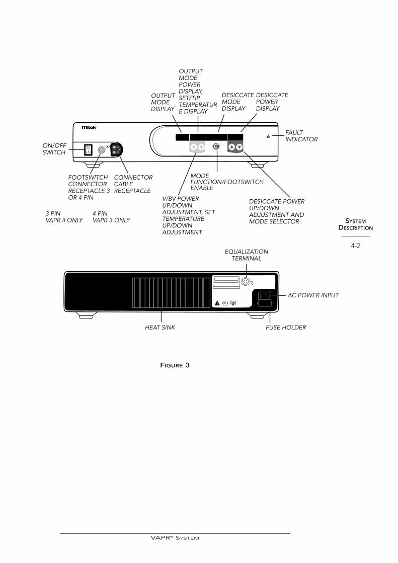
VAPR GENERATOR The VAPR Generator (FIGURE 3) is an isolated output radiofrequency generator thatprovides power for soft tissue vaporization, cutting and coagulation duringarthroscopic surgical procedures. Technical specifications are detailed in Appendix A.
OUTPUT MODESThe VAPR Generator allows the user to select one of the following functional modes:a tissue Vaporization mode, or a Blended Vaporization mode that combinesVaporization and Desiccation using generator set-up options, with the selectedoutput mode activated using the Yellow footswitch pedal. The Desiccation(hemostasis) mode is activated using the Blue footswitch pedal. A brief description ofeach mode is provided below:
Vaporization (V) Modes
There are three standard V mode levels V1, V 2 and V3. The least aggressivetissue vaporization is created in the V1 mode while the most aggressive tissuevaporization is created in the V3 mode.
Desiccate (DES) Mode
The Desiccate mode provides hemostasis of blood vessels without tissuevaporization. Available with all Electrode configurations, the hemostatic effectwill be dependent on the active electrode contact area and power setting. Thedepth of effect for a given Electrode configuration and power setting isdependent upon the application time.
DES with Temp Indication
When in desiccation mode, this allows the display of electrode tip temperature,and control against a set temperature.
Blended Vaporization (BV) Modes
There are two Blended Vaporization modes: BV1 and BV2. The BlendedVaporization output modes combine tissue vaporization with hemostasis and areuseful when cutting or de-bulking more vascular tissue structures.
• BV1 mode automatically switches between a V2 vaporization mode anddesiccate (hemostasis) mode.
• BV2 mode switches between the V3 vaporization mode and desiccate(hemostasis) mode.
SYSTEMDESCRIPTION
CRIPTION
4-1
VAPR® SYSTEM
SYSTEMDESCRIPTION
4-2
®
FIGURE 3
ON/OFFSWITCH
FOOTSWITCHCONNECTORRECEPTACLE 3OR 4 PIN
CONNECTORCABLERECEPTACLE
V/BV POWERUP/DOWNADJUSTMENT, SETTEMPERATUREUP/DOWNADJUSTMENT
EQUALIZATIONTERMINAL
HEAT SINK
AC POWER INPUT
FUSE HOLDER
DESICCATE POWERUP/DOWNADJUSTMENT ANDMODE SELECTOR
MODEFUNCTION/FOOTSWITCHENABLE
FAULTINDICATOR
OUTPUTMODEDISPLAY
OUTPUTMODEPOWER DISPLAY,SET/TIPTEMPERATURE DISPLAY
DESICCATEMODE DISPLAY
DESICCATEPOWER DISPLAY
3 PIN VAPR II ONLY
4 PINVAPR 3 ONLY
VAPR® SYSTEM
SYSTEMDESCRIPTION
4-3
GENERATOR CONTROLS AND DISPLAYS
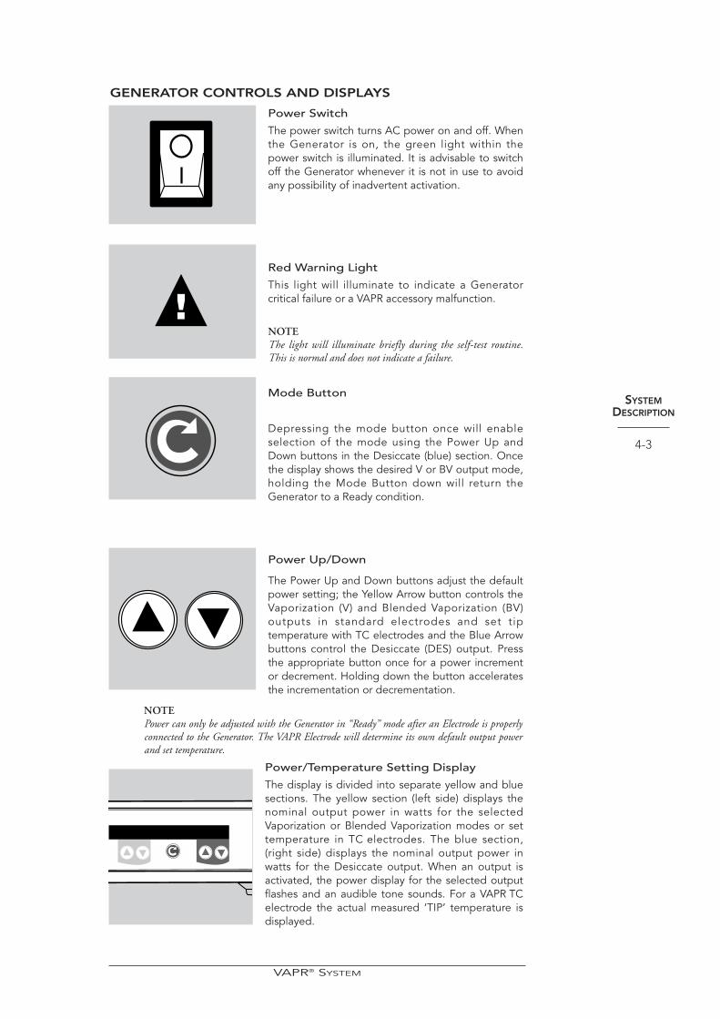
Power Switch
The power switch turns AC power on and off. Whenthe Generator is on, the green light within thepower switch is illuminated. It is advisable to switchoff the Generator whenever it is not in use to avoidany possibility of inadvertent activation.
Red Warning Light
This light will illuminate to indicate a Generatorcritical failure or a VAPR accessory malfunction.
NOTEThe light will illuminate briefly during the self-test routine.This is normal and does not indicate a failure.
Mode Button
Depressing the mode button once will enableselection of the mode using the Power Up andDown buttons in the Desiccate (blue) section. Oncethe display shows the desired V or BV output mode,holding the Mode Button down will return theGenerator to a Ready condition.
Power Up/Down
The Power Up and Down buttons adjust the defaultpower setting; the Yellow Arrow button controls theVaporization (V) and Blended Vaporization (BV)outputs in standard electrodes and set tiptemperature with TC electrodes and the Blue Arrowbuttons control the Desiccate (DES) output. Pressthe appropriate button once for a power incrementor decrement. Holding down the button acceleratesthe incrementation or decrementation.
NOTE Power can only be adjusted with the Generator in “Ready” mode after an Electrode is properlyconnected to the Generator. The VAPR Electrode will determine its own default output powerand set temperature.
Power/Temperature Setting Display
The display is divided into separate yellow and bluesections. The yellow section (left side) displays thenominal output power in watts for the selectedVaporization or Blended Vaporization modes or settemperature in TC electrodes. The blue section,(right side) displays the nominal output power inwatts for the Desiccate output. When an output isactivated, the power display for the selected outputflashes and an audible tone sounds. For a VAPR TCelectrode the actual measured ‘TIP’ temperature isdisplayed.
VAPR® SYSTEM

FRONT PANEL DISPLAY SYMBOLS
Indicates that the output mode for yellow pedal activation can be selected.
Indicates that the footswitch is the activation source for the system.
Indicates that the audio alarm output level may be selected. “MIN” is the lowestvolume available, “MAX” is the loudest.
Indicates that the Generator is waiting for the Electrode/HandpieceCable to be attached to the front panel receptacle.
Indicates that the Generator is waiting for an Electrode to be inserted into theHandpiece. Not displayed when using the electrode with integrated cable.
NOTEMode selection can only be performed after an Electrode and Handpiece are connected to theGenerator. If the Mode button is quickly pressed and released the next user set-up optionappears.
May appear if the active tip shorts against nearby metal objects. A warning tone willalso be issued. Press the mode button on the front panel or the third footswitchbutton to resume operation, for TC electrodes only.
For all other electrode types operation will resume automatically when the short isremoved (provided foot-pedal remains depressed).
Indicates that the Footswitch menu option is in the default off position.
SYSTEMDESCRIPTION
4-4
VAPR II ONLY
VAPR 3 ONLY
VAPR 3 ONLY
ALARM VOLUME
FOOTSWITCH
CONNECT CABLE
INSERT ELECTRODE
OUTPUT SHORTED
FOOT MENU OFF
OUTPUT (YEL)
VAPR® SYSTEM
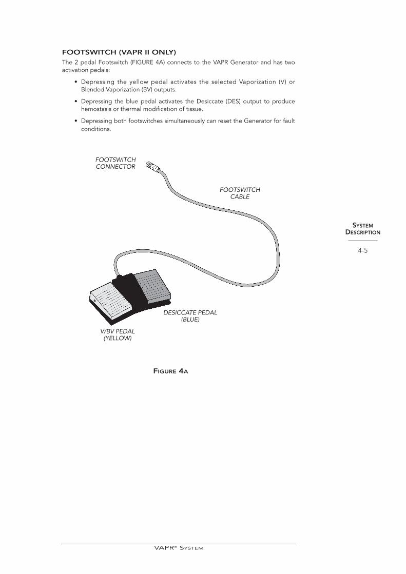
FOOTSWITCH (VAPR II ONLY)The 2 pedal Footswitch (FIGURE 4A) connects to the VAPR Generator and has twoactivation pedals:
• Depressing the yellow pedal activates the selected Vaporization (V) orBlended Vaporization (BV) outputs.
• Depressing the blue pedal activates the Desiccate (DES) output to producehemostasis or thermal modification of tissue.
• Depressing both footswitches simultaneously can reset the Generator for faultconditions.
SYSTEMDESCRIPTION
4-5
VAPR® SYSTEM
V/BV PEDAL (YELLOW)
DESICCATE PEDAL(BLUE)
FOOTSWITCHCONNECTOR
FOOTSWITCHCABLE
FIGURE 4A

FOOTSWITCH (VAPR 3 ONLY)The VAPR 3 Footswitch (FIGURE 4B) connects to the VAPR Generator. The yellowand blue pedals are used for output activation with the menu/reset button for faultclearance or remote adjustment of the output settings (if enabled as shown below).
• Depressing the yellow pedal activates the selected Vaporization (V) orBlended Vaporization (BV) outputs.
• Depressing the blue pedal activates the Desiccate (DES) output to producehemostasis or thermal modification of tissue.
• Depressing the menu/reset button can reset the Generator from a faultcondition.
Enabling of Footswitch Setting Feature (software version V1.02 onwards)
• In the “ready” state, press the mode function button (as shown on Figure 3)three times, the display will show “FOOT MENU OFF” (the VAPR 3 system issupplied with “OFF” as default).
• Press either of the blue arrow buttons to toggle the state until the displayindicates “FOOT MENU ON”.
• Press the mode function button until the generator returns to the “ready”state.
• When enabled as described above the output settings may be controlled asfollows:
• Depressing and releasing the menu/reset button when the VAPR Generator iswaiting for user interaction (“ready” state) will initiate a setting adjustmentprocedure.
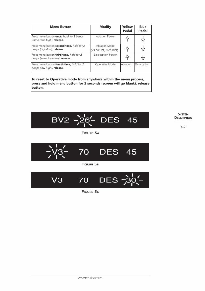
• After pressing the menu/reset button the first time the VAPR Generator willemit two short beeps and start flashing, the vaporize mode power settings onthe left of display as shown in FIGURE 5A.
• While the power setting is flashing, holding down the blue pedal will reducethe value and holding down the yellow pedal will increase it.
• Pressing the menu/reset button once more will advance the setting to thevaporize waveform which will start to flash rapidly on the display. Pressing andreleasing the yellow or blue pedals will cycle through the availability modifiers(FIGURE 5B).
• Pressing the menu/reset button again will cause the DES power setting toflash as per FIGURE 5C so that it may be adjusted in the same way as theV/BV power.
• Pressing the menu/reset button once more resumes the “ready” state with astatic display.
SYSTEMDESCRIPTION
4-6
FIGURE 4B
VAPR® SYSTEM
NOTEIn some versions of the 3 input footswitch the menu/reset button will be replaced by a graypedal. For VAPR 3 systems with software V1.01 the footswitch setting feature is alwaysenabled.
SYSTEMDESCRIPTION
4-7
Menu Button
Press menu button once, hold for 2 beeps(same tone-high), release.
Press menu button second time, hold for 2beeps (high-low), release.
Press menu button third time, hold for 2beeps (same tone-low), release.
Press menu button fourth time, hold for 2beeps (low-high), release.
Modify
Ablation Power
Ablation Mode
(V3, V2, V1, BV2, BV1)
Desiccation Power
Operative Mode
YellowPedal
BluePedal
DesiccationAblation
To reset to Operative mode from anywhere within the menu process,press and hold menu button for 2 seconds (screen will go blank), releasebutton.
BV2 26 DES 45
V3 70 DES 45
V3 70 DES 30
FIGURE 5B
FIGURE 5C
FIGURE 5A
VAPR® SYSTEM

SYSTEMDESCRIPTION
4-8
VAPR ELECTRODES
The family of VAPR Electrodes has been designed to facilitate access and control thedelivery of energy to the joint space. Each Electrode contains an internalclassification code which automatically adjusts the VAPR Generator to the optimaloutput power setting. The VAPR Electrode has an integrated “return” electrode onits shaft, eliminating the need for a conventional patient ground pad. AngledElectrode styles are also available to facilitate tissue access and positioning duringuse.
The working tips of the Electrodes can be divided into seven main functional typesaccording to the geometry of the active electrode and insulation support:
VAPR S50 Electrode
The forward facing active tip is designed to facil itatecontrolled, precise tissue effects. The RF probe, with angledshaft is intended to be used for removal of soft tissue duringArthroscopic procedures in smaller, more difficult areas of theanatomy to access such as the knee (i.e., posterior horn ofmeniscus). The integral Suction Port allows bubbles andvaporization products to be removed. The design provides alarge area suction path which attracts difficult to access frondtissue to the tip and helps minimize clogging.
LDS, LPS, and VAPR S90 Electrodes
The side facing electrode is designed to maximize the tiptissue contact area and provide rapid tissue debulking. Theelectrode has a large tip-shaft offset which maximizes tactilefeedback and facilitates removal of difficult to reach tissue. Theintegral Suction Port allows bubbles and vaporization productsto be removed. The design provides a large area suction pathwhich attracts difficult to access frond tissue to the tip andhelps minimize clogging.
Additionally, the forward facing end of the manifold may beuseful in protecting adjacent structures from inadvertent injuryduring activation.
3.5 Side Effect Electrode
The side-facing electrode is designed to maximize tissuecontact area and produce rapid tissue debulking. The active,tissue contact electrode is mounted on the side of the workingtip with the return electrode extending over the insulator onthe opposite side of the active electrode. This configuration isparticularly useful in engaging tissue which is approached atan acute angle. Additionally, the insulator and return electrodeassist in protecting adjacent structures from inadvertent injuryduring activation. The larger contact area of the electrodemeans that these electrodes also produce effective hemostasisof blood vessels.
VAPR® SYSTEM
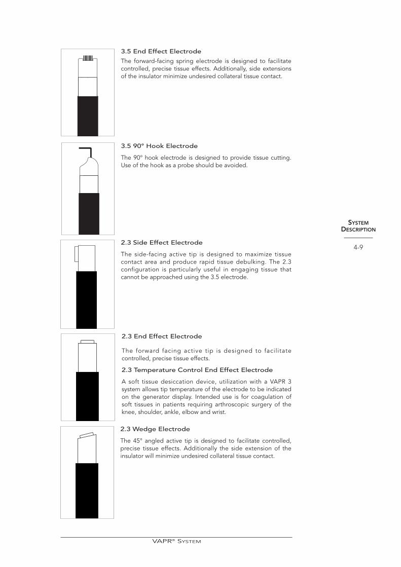
3.5 End Effect Electrode
The forward-facing spring electrode is designed to facilitatecontrolled, precise tissue effects. Additionally, side extensionsof the insulator minimize undesired collateral tissue contact.
3.5 90° Hook Electrode
The 90° hook electrode is designed to provide tissue cutting.Use of the hook as a probe should be avoided.
2.3 Side Effect Electrode
The side-facing active tip is designed to maximize tissuecontact area and produce rapid tissue debulking. The 2.3configuration is particularly useful in engaging tissue thatcannot be approached using the 3.5 electrode.
2.3 End Effect Electrode
The forward facing active tip is designed to facilitatecontrolled, precise tissue effects.
2.3 Temperature Control End Effect Electrode
A soft tissue desiccation device, utilization with a VAPR 3system allows tip temperature of the electrode to be indicatedon the generator display. Intended use is for coagulation ofsoft tissues in patients requiring arthroscopic surgery of theknee, shoulder, ankle, elbow and wrist.
2.3 Wedge Electrode
The 45° angled active tip is designed to facilitate controlled,precise tissue effects. Additionally the side extension of theinsulator will minimize undesired collateral tissue contact.
SYSTEMDESCRIPTION
4-9
VAPR® SYSTEM
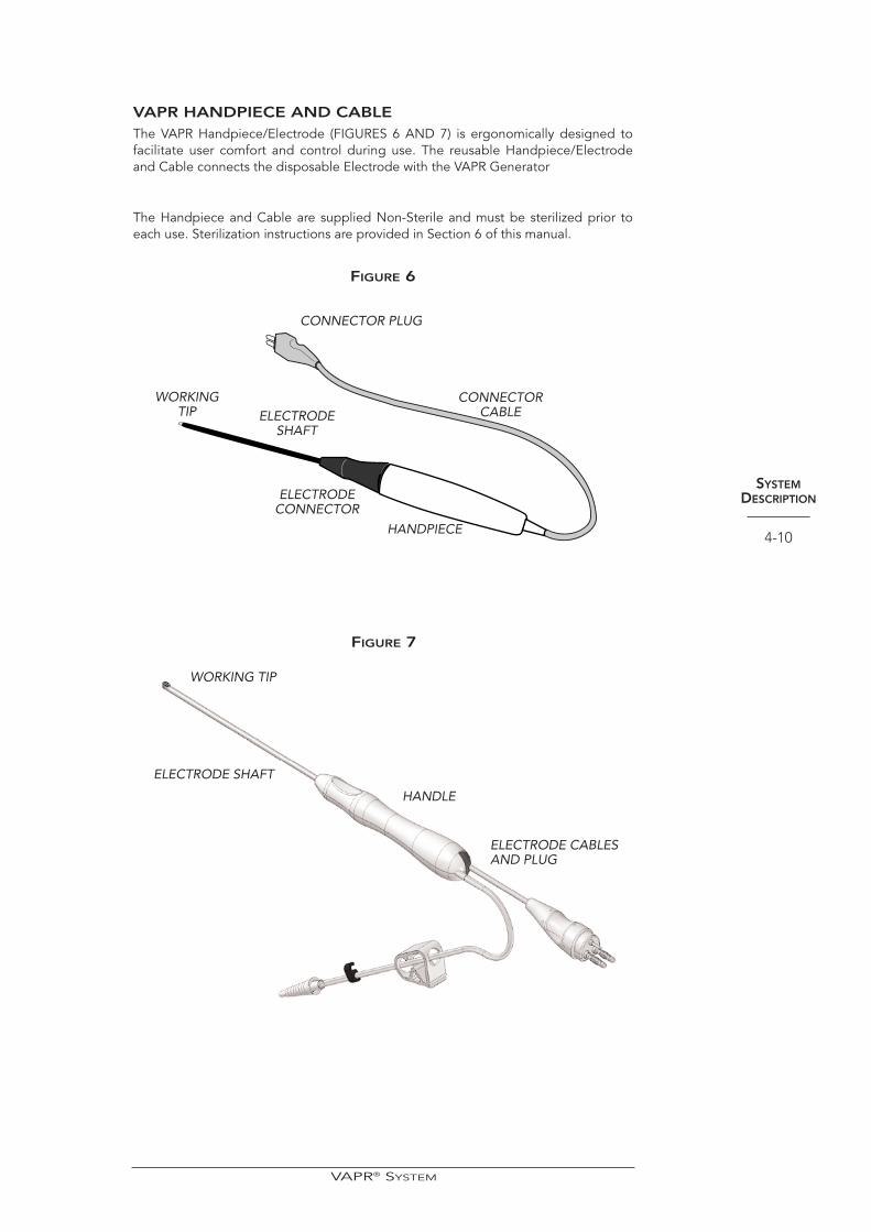
VAPR HANDPIECE AND CABLEThe VAPR Handpiece/Electrode (FIGURES 6 AND 7) is ergonomically designed tofacilitate user comfort and control during use. The reusable Handpiece/Electrodeand Cable connects the disposable Electrode with the VAPR Generator
The Handpiece and Cable are supplied Non-Sterile and must be sterilized prior toeach use. Sterilization instructions are provided in Section 6 of this manual.
FIGURE 6
SYSTEMDESCRIPTION
4-10
CONNECTOR PLUG
CONNECTORCABLE
HANDPIECE
WORKINGTIP ELECTRODE
SHAFT
ELECTRODECONNECTOR
VAPR® SYSTEM
WORKING TIP
ELECTRODE SHAFT
FIGURE 7
HANDLE
ELECTRODE CABLESAND PLUG
INSTRUCTIONSFOR USE
5-1
Section 5
INSTRUCTIONSFOR USE
NOTEThe Manufacturer is responsible for safety, reliability, and performance of equipment only if:
• Installation procedures in this manual are followed.
• Assembly operations, extensions, readjustments, modifications or repairs are carried out bypersons authorized by the manufacturer and the electrical installation of the relevantoperating room complies with the local codes and regulatory requirements governing suchfacilities.
• The equipment is used in accordance with these instructions.
The Mitek VAPR System unit has been designed as a system, with accessory features specificallydesigned to maximize safety and effectiveness. Use only the Mitek Handpiece and Electrodeswith this System.
SYSTEM INSTALLATION1. Place the Generator on a table, cart racking system or other stable platform
that can be positioned as close as possible to the operative site during use.
2. Provide at least four inches of space from the rear of the Generator. Nevercover the Generator or stack other equipment on top of it other than in astandard cart system. Ensure adequate ventilation, as it is normal for theGenerator to become warm during use.
CAUTIONEMC CONSIDERATIONS
• Provide as much separation as possible between the generator and other electronic equipment(such as monitors). When activating the generator, unintended electromagnetic coupling maycause interference with the other equipment.
• Should any unintentional effects appear upon other equipment when using the generator,repositioning the generator, the connecting leads or other equipment may alleviate the problem.It may also help to use different mains supply sockets for any affected equipment
• The generator should not be used adjacent to or stacked with other electrical equipment. Ifadjacent or stacked use is necessary both the generator and other equipment should be observedto verify normal operation in the configuration in which it will be used.
• The EMC classification of the VAPR 3 system (class A) is suitable for use on dedicated supplysystems not connected to the public mains network, such as hospitals.
NOTE: Although class A limits have been derived for industrial and commercial establishments,administrations may allow, with whatever additional measures necessary, the installation anduse of class A ISM equipment in a domestic establishment or establishment connected directlyto domestic electricity power supplies.
VAPR® SYSTEM
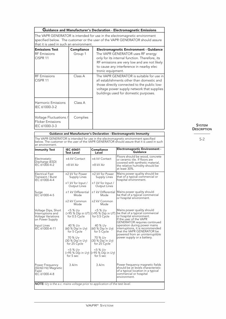
Guidance and Manufacturer's Declaration - Electromagnetic Emissions
The VAPR GENERATOR is intended for use in the electromagnetic environmentspecified below. The customer or the user of the VAPR GENERATOR should assurethat it is used in such an environment.
Emissions Test Compliance Electromagnetic Environment - GuidanceRF Emissions Group 1 The VAPR GENERATOR uses RF energy CISPR 11 only for its internal function. Therefore, its
RF emissions are very low and are not likely to cause any interference in nearby electronic equipment.
RF Emissions Class A The VAPR GENERATOR is suitable for use in CISPR 11 all establishments other than domestic and
those directly connected to the public low-voltage power supply network that supplies buildings used for domestic purposes.
Harmonic Emissions Class AIEC 61000-3-2
Voltage Fluctuations / CompliesFlicker EmissionsIEC 61000-3-3 SYSTEM
DESCRIPTION
5-2
VAPR® SYSTEM
Guidance and Manufacturer's Declaration - Electromagnetic Immunity
The VAPR GENERATOR is intended for use in the electromagnetic environment specifiedbelow. The customer or the user of the VAPR GENERATOR should assure that it is used in suchan environment.
Immunity Test IEC 60601 Compliance Test Level Level
Electrostatic ±6 kV Contact ±6 kV Contact Discharge (ESD) IEC 61000-4-2 ±8 kV Air ±8 kV Air
Electrical Fast ±2 kV for Power ±2 kV for Power Transient / Burst Supply Lines Supply Lines IEC 61000-4-4
±1 kV for Input / ±1 kV for Input /Output Lines Output Lines
Surge ±1 kV Differential ±1 kV Differential IEC 61000-4-5 Mode Mode
±2 kV Common ±2 kV CommonMode Mode
Voltage Dips, Short <5 % UT <5 % UTInterruptions and (>95 % Dip in UT) (>95 % Dip in UT) Voltage Variations for 0.5 Cycle for 0.5 Cycle on Power Supply
Input Lines 40 % UT 40 % UTIEC 61000-4-11 (60 % Dip in UT) (60 % Dip in UT)
for 5 Cycle for 5 Cycle
70 % UT 70 % UT(30 % Dip in UT) (30 % Dip in UT)for 25 Cycle for 25 Cycle
<5 % UT <5 % UT(>95 % Dip in UT) (>95 % Dip in UT)for 5 sec for 5 sec
Power Frequency 3 A/m 3 A/m (50/60 Hz) Magnetic Field IEC 61000-4-8
Floors should be wood, concreteor ceramic tile. If floors arecovered with synthetic material,the relative humidity should beat least 30%.
Mains power quality should bethat of a typical commercial or hospital environment.
Mains power quality should be that of a typical commercialor hospital environment.
Mains power quality should be that of a typical commercialor hospital environment.If the user of the VAPR GENERATOR requires continuedoperation during power mainsinterruptions, it is recommendedthat the VAPR GENERATOR bepowered from an uninterruptiblepower supply or a battery.
Power frequency magnetic fieldsshould be at levels characteristicof a typical location in a typicalcommercial or hospitalenvironment.
Electromagnetic Environment - Guidance
NOTE: UT is the a.c. mains voltage prior to application of the test level.
SYSTEMDESCRIPTION
5-3
VAPR® SYSTEM
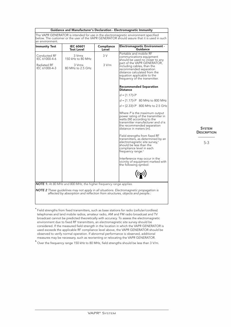
Guidance and Manufacturer's Declaration - Electromagnetic Immunity
The VAPR GENERATOR is intended for use in the electromagnetic environment specifiedbelow. The customer or the user of the VAPR GENERATOR should assure that it is used in suchan environment.
Immunity Test IEC 60601 Compliance Test Level Level
Conducted RF 3 Vrms 3 VIEC 61000-4-6 150 kHz to 80 MHz
Radiated RF 3 Vrms 3 V/mIEC 61000-4-3 80 MHz to 2.5 GHz
Portable and mobile RFcommunications equipmentshould be used no closer to anypart of the VAPR GENERATOR,including cables, than therecommended separationdistance calculated from theequation applicable to thefrequency of the transmitter.
Recommended SeparationDistance
d = [1.17]√P
d = [1.17]√P 80 MHz to 800 MHz
d = [2.33]√P 800 MHz to 2.5 GHz
Where P is the maximum outputpower rating of the transmitter inwatts (W) according to thetransmitter manufacturer and d isthe recommended separationdistance in meters (m).
Field strengths from fixed RFtransmitters, as determined by anelectromagnetic site survey,a
should be less than thecompliance level in eachfrequency range.b
Interference may occur in thevicinity of equipment marked withthe following symbol:
Electromagnetic Environment - Guidance
NOTE 1: At 80 MHz and 800 MHz, the higher frequency range applies.
NOTE 2 These guidelines may not apply in all situations. Electromagnetic propagation isaffected by absorption and reflection from structures, objects and people.:
aField strengths from fixed transmitters, such as base stations for radio (cellular/cordless)telephones and land mobile radios, amateur radio, AM and FM radio broadcast and TVbroadcast cannot be predicted theoretically with accuracy. To assess the electromagneticenvironment due to fixed RF transmitters, an electromagnetic site survey should beconsidered. If the measured field strength in the location in which the VAPR GENERATOR isused exceeds the applicable RF compliance level above, the VAPR GENERATOR should beobserved to verify normal operation. If abnormal performance is observed, additionalmeasures may be necessary, such as reorienting or relocating the VAPR GENERATOR.
bOver the frequency range 150 kHz to 80 MHz, field strengths should be less than 3 V/m.
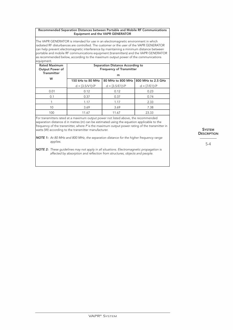
Recommended Separation Distances between Portable and Mobile RF CommunicationsEquipment and the VAPR GENERATOR
The VAPR GENERATOR is intended for use in an electromagnetic environment in whichradiated RF disturbances are controlled. The customer or the user of the VAPR GENERATORcan help prevent electromagnetic interference by maintaining a minimum distance betweenportable and mobile RF communications equipment (transmitters) and the VAPR GENERATORas recommended below, according to the maximum output power of the communicationsequipment.
150 kHz to 80 MHz 80 MHz to 800 MHz 800 MHz to 2.5 GHz
d = [3.5/V1]√P d = [3.5/E1]√P d = [7/E1]√P
0.01 0.12 0.12 0.23
0.1 0.37 0.37 0.74
1 1.17 1.17 2.33
10 3.69 3.69 7.38
100 11.67 11.67 23.33
For transmitters rated at a maximum output power not listed above, the recommendedseparation distance d in metres (m) can be estimated using the equation applicable to thefrequency of the transmitter, where P is the maximum output power rating of the transmitter inwatts (W) according to the transmitter manufacturer.
NOTE 1: At 80 MHz and 800 MHz, the separation distance for the higher frequency rangeapplies.
NOTE 2: These guidelines may not apply in all situations. Electromagnetic propagation isaffected by absorption and reflection from structures, objects and people.
SYSTEMDESCRIPTION
5-4
VAPR® SYSTEM
Separation Distance According toFrequency of Transmitter
m
Rated MaximumOutput Power of
Transmitter
W

INSTRUCTIONSFOR USE
5-5
3. Insert the power cord into the Power Cord Receptacle on the back of theGenerator. A standard hospital grade power cord is necessary for properconnection of the Generator to the power source. To ensure user safety, theGenerator must be properly grounded through the power cord and poweroutlet.
4. Connect the power cord from the Generator directly to an AC source. TheGenerator is designed to operate as shipped with full regulation between 90-132 VAC or 198-264 VAC at 50-60 Hz. This allows the Generator output toremain constant in case of brownouts or power surges.
WARNINGThe power cord must meet all requirements for safe grounding. Its purpose should not bedefeated by using extension cords, multiple plug points or three pronged to two prongedadapters. Power cords should always be grasped by the plug. Do not pull the cord itself.
5. Connect the Footswitch to the receptacle on the front of the Generator.
6. Press the Generator power switch to the ON position. Verify that the greenlight in the switch illuminates. When the Generator is first switched on prior toElectrode connection a system self-check sequence will be initiated.
7. Verify that the “CONNECT CABLE” is flashing on the display prompt on thefront of the Generator. This completes the Generator installation procedure.Turn the generator power switch OFF when not in use.
SYSTEM SETUP AND USE DURING SURGERYVAPR II ONLY
VAPR II System Component Requirements:
• A properly installed VAPR II Generator with attached 2 pedal Footswitch
• A Sterile VAPR Handpiece and Cable or VAPR Electrode with
Integrated Handpiece
• A VAPR Electrode appropriate to the procedure being undertaken
VAPR 3 ONLY
VAPR 3 System Component Requirements:
• A properly installed VAPR 3 Generator with attached VAPR 3 Footswitch
• A Sterile VAPR Handpiece and Cable
• A VAPR Electrode appropriate to the procedure being undertake
NOTE The VAPR Handpiece and Cable are supplied NON-STERILE. Refer to Section 6 of thismanual for sterilization instructions prior to use.
1. Press the Generator power switch to the ON position. Verify that the greenlight in the switch illuminates and that the system self-check sequence isinitiated.
2. Verify that the “CONNECT CABLE” symbol is flashing on the Generatordisplay, indicating that the Generator is in idle mode.
3. Inside the sterile field, pass the plug end of the sterile Handpiece/ElectrodeCable out of the sterile field, and connect it to the front of the Generator.
VAPR® SYSTEM
INSTRUCTIONSFOR USE
5-6
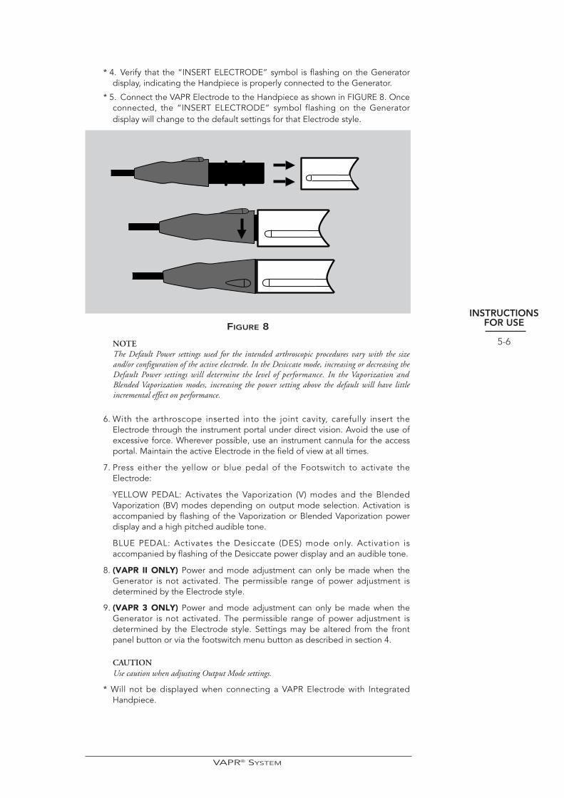
* 4. Verify that the “INSERT ELECTRODE” symbol is flashing on the Generatordisplay, indicating the Handpiece is properly connected to the Generator.
* 5. Connect the VAPR Electrode to the Handpiece as shown in FIGURE 8. Onceconnected, the “INSERT ELECTRODE” symbol flashing on the Generatordisplay will change to the default settings for that Electrode style.
FIGURE 8
NOTEThe Default Power settings used for the intended arthroscopic procedures vary with the sizeand/or configuration of the active electrode. In the Desiccate mode, increasing or decreasing theDefault Power settings will determine the level of performance. In the Vaporization andBlended Vaporization modes, increasing the power setting above the default will have littleincremental effect on performance.
6. With the arthroscope inserted into the joint cavity, carefully insert theElectrode through the instrument portal under direct vision. Avoid the use ofexcessive force. Wherever possible, use an instrument cannula for the accessportal. Maintain the active Electrode in the field of view at all times.
7. Press either the yellow or blue pedal of the Footswitch to activate theElectrode:
YELLOW PEDAL: Activates the Vaporization (V) modes and the BlendedVaporization (BV) modes depending on output mode selection. Activation isaccompanied by flashing of the Vaporization or Blended Vaporization powerdisplay and a high pitched audible tone.
BLUE PEDAL: Activates the Desiccate (DES) mode only. Activation isaccompanied by flashing of the Desiccate power display and an audible tone.
8. (VAPR II ONLY) Power and mode adjustment can only be made when theGenerator is not activated. The permissible range of power adjustment isdetermined by the Electrode style.
9. (VAPR 3 ONLY) Power and mode adjustment can only be made when theGenerator is not activated. The permissible range of power adjustment isdetermined by the Electrode style. Settings may be altered from the frontpanel button or via the footswitch menu button as described in section 4.
CAUTIONUse caution when adjusting Output Mode settings.
* Will not be displayed when connecting a VAPR Electrode with IntegratedHandpiece.
VAPR® SYSTEM
USING VAPR TC ELECTRODES• When attaching the VAPR TC electrode the generator will automatically
configure itself in temperature control mode, the display will indicate thedefault SET temperature and desiccation power. The vaporization output isinhibited, pressing the yellow pedal will have no effect.
• (VAPR II ONLY) The SET temperature may be adjusted from its default usingthe yellow Up/Down buttons. Similarly the Desiccation power may beadjusted using the blue Up/Down buttons ‘on the generator’.
• (VAPR 3 ONLY) The SET temperature may be adjusted from its default usingthe yellow Up/Down buttons. Similarly the Desiccation power may beadjusted using the blue Up/Down buttons ‘on the generator’. These settingsmay also be changed through the menu button adjustment proceduredescribed in section 4.
• Power, SET and mode adjustment can only be made when the generator isnot activated.
• During activation, the display will change from the SET temperature to theactual measured TIP temperature.
• The system will only deliver power up to the limit indicated on the display.Occasionally, during high interjoint flow conditions the desired SETtemperature cannot be reached. If this occurs, increase the power from itsdefault setting in small increments until correct temperature control ispossible.
• For user convenience an over-temperature indicator is operational intemperature control mode, an audible tone will sound if the measured TIPtemperature reaches more than 8ºC over the SET temperature.
NOTECertain conditions may momentarily cause temperature overshoot and trigger the overtemperature indicator. Once triggered the tone will sound for a minimum of 1 second. Possiblecauses are:
1. Excessive power used with low/no flow environment.
2. Insufficient saline around tip.
3. Unstable surgical environment, excessive changes in saline flow rate and/or volume.
4. Incorrect irrigation solution used.
ADJUSTING THE TONE VOLUME The activation tone volume can be adjusted using the following procedure:
• Press and release the Mode button until VOLUME appears on the display.
• Press the Power Up button in the Desiccate (blue) section.
• The tone can be verified by depressing the down button of the Desiccate(blue) power control during selection.
• Press and release the Mode button once more to return the Generator toReady mode.
NOTEFamiliarize yourself with the two audible output tones to verify output selection as it is oftendifficult to visualize the activation pedals (footswitch) during arthroscopic surgery.
INSTRUCTIONSFOR USE
5-7
VAPR® SYSTEM

INSTRUCTIONSFOR USE
5-8
ADJUSTING THE FOOTSWITCH/HANDSWITCH OPTION(VAPR II ONLY)
NOTEThis feature is not available as of the printing of this manual.
To configure the generator for an optional handswitch accessory use the followingprocedure:
• Press and release the mode button until FOOTSWITCH appears on thedisplay.
• Press the Power Up button in the Desiccate (blue) section until HANDSWITCHappears in the display.
• Press and release the mode button until the display changes to the Readymode. Handswitching is now active.
• To return to footswitch operation follow the above procedure, insteadselecting footswitch.
NOTE• The footswitch will become inactive when handswitch is selected.
• Switching the generator off will reset the generator to footswitch operation.
CHANGING ELECTRODES DURING SURGERYAn Electrode can be removed from the Handpiece by unlocking the connectorassembly and then pulling the Electrode and Handpiece apart.
Once the Electrode is disconnected, the Generator will automatically enter idlemode with the display showing the “INSERT ELECTRODE” symbol.
Fit a new sterile Electrode as previously described. If the new Electrode has differentdefault settings to the previous Electrode, check that the Generator display matchesthe Electrode default settings specified on the package insert.
NOTEWhen switching to or from a VAPR electrode with Integrated Cable, the generatorwill display “CONNECT CABLE”
If the new Electrode has identical default settings to the previous Electrode, theGenerator will retain the settings previously displayed prior to changing the Electrode.
Switching the Generator power off will clear all output adjustments.
WARNINGDo not insert or withdraw Electrodes while activated. Injury and/or product damage mayresult.
NOTE In the event of a power failure, or if the Generator is turned off while an Electrode is connectedto the Generator, the Generator will default to its lowest output power level, 5 watts, whenpower is restored. The power can be increased using the Power Up button.
Recommendations
• Unless circumstances dictate otherwise, use the Electrode default power andmode settings to enhance patient and user safety.
• Remove any tissue buildup from Electrodes to maximize surgical effect.
• Avoid any unnecessary and prolonged Electrode activation to preventoverheating.
• When de-bulking or vaporizing tissue, apply firm pressure using a progressivesurface brushing technique. Avoid burying the electrode in the tissue as thiscould increase debris formation.
• The speed of tissue de-bulking will be determined by the output modeselection, size and style of the Electrode, and application technique.
VAPR® SYSTEM

INSTRUCTIONSFOR USE
5-9
• When rapidly de-bulking or vaporizing tissue some browning of the tissue canbe anticipated. This can either be brushed away with a non-activatedelectrode or ablated using gentle application pressure during activation.
• If more than one style of Electrode is used during a procedure, the Generatorwill revert to the default settings defined by each Electrode style.
• Bubbles are produced during tissue vaporization which may interrupt surgeryby temporarily interfering with vision. A continuous flow fluid managementsystem is recommended to prevent accumulation and remove bubbles, aswell as any particulate products of vaporization, from the operative field.
WARNINGAvoid bubble accumulation in the joint space during use. The accumulation of bubbles aroundthe working tip of the Electrode will diminish performance and may produce overheatingsufficient to damage adjacent structures.
USE OF SUCTION ELECTRODES/SHEATHS
Suction electrodes and sheaths are designed to provide improvedvisibility at the operative site whilst facilitating removal of degradationproducts. To avoid premature clogging of the suction pathways inthese devices.
• Close the pinch/roller clamp before insertion of the device intopatient.
• Open the pinch/roller clamp immediately prior to activation(ablation).
• Close the pinch/roller clamp immediately after device activation(ablation).
• The pinch/roller clamp should not be opened for tissuemodification or the sealing of blood vessels (blue pedal use) asthe suction flow may suck unintended tissue into the device andcause clogging.
In the case of blocked suction electrodes activation of the device insaline at its maximum power for a few seconds may restore the suctionpathway.
AFTER SURGERYAfter surgery, you need to perform the following:
• Withdraw the Electrode.
• Disassemble the Electrode and Handpiece.
• Dispose of the SINGLE-USE VAPR Electrodes.
• Prepare the Handpiece and Cable for steam autoclave processing.
IMPORTANTDisconnecting the Electrode/Handpiece will automatically result in the “CONNECT CABLE”idle mode symbol. The Generator can be left in this mode between cases but at the end of theoperating session must be switched off from the power supply.
VAPR® SYSTEM

CLEANING ANDSTERILIZATIONPROCEDURES
6-1
Section 6
CLEANING ANDSTERILIZATIONPROCEDURES
CLEANING THE GENERATORThe VAPR Generator cannot be sterilized. The Generator surfaces can be cleanedwith a non-abrasive cleaning agent. Do not allow fluids to enter the Generatorconnectors.
CLEANING THE FOOTSWITCHThe VAPR Footswitch cannot be sterilized. The Footswitch surfaces can be cleanedwith detergents and disinfectant cleaners according to standard hospital practices.
NOTEThe use of strong alkali detergents or cleaners must be avoided as these may damage the device.
CLEANING AND STERILIZING THE VAPR HANDPIECE ANDCABLE
1. Remove all gross matter (blood, mucous, tissue) by wiping each componentwith a cloth or gauze pad and a mild cleaning solution or blood-dissolvingdetergent.
NOTEThe accessories are delicate surgical instruments. Do not immerse in reprocessing solutions. Donot use abrasive cleaning agents. Product damage may otherwise result.
2. Rinse thoroughly in running water.
3. Allow the Handpiece to drain thoroughly.
4. Remove residual cleansing agents with a damp cloth.
5. Dry the accessory devices thoroughly before sterilizing.
STEAM STERILIZATION PROCEDURE• Wrapped Pre-Vacuum Cycle: 134 to 136°C for 3 to 4 minutes.
• Drying times may vary with the type of wrapping material. Please refer to thesterilizer manufacturer for recommended drying times.
• After any sterilization and cleaning process, check the Handpiece for anydamage (e.g. crush damage, cracking, or distortion). Discard if damage isobserved.
WARNING The Mitek Handpiece and Cable is intended for 20 reuse cycles only. Exceeding therecommended number of uses may result in electrical or mechanical failure during use ordifficulty when assembling or disassembling the Electrode with the Handpiece.
VAPR® SYSTEM
Section 7
PERIODICMAINTENANCE
INSPECTION
The manufacturer recommends that the VAPR Generator be regularly inspected toensure continued safety of operation throughout its service life. The following safetychecks should be performed at least every 12 months by a qualified person who hasadequate training, knowledge and practical experience to perform such tests.
• Inspect the Generator and the Footswitch for obvious signs of mechanicaldamage or wear. Ensure that the Generator case shows no sign of tampering.There are no user serviceable items within the Generator or Footswitch.
• Check that the Generator back panel label is present and decipherable andthat the front panel markings and symbols are still legible.
• Retract the fuse drawer of the mains inlet connector and verify that both fusesare intact and match the rated current and breaking characteristics as per theback panel label.
• Verify that the resistance between the earth terminal of the mains inletconnector and the Generator enclosure is within the limits defined in IEC60601-1 or the corresponding national standard as applicable.
• Switch on the Generator ensuring that the initial internal self-test completesnormally as reported on the front panel display. Check that the audio alarm,front panel warning indicator and vacuum fluorescent display are functioningnormally via the user verification sequence which follows initialization.
• Check that the enclosure earth leakage current is within the limits for Class Iequipment as prescribed with IEC 60601-1 or the corresponding nationalstandard as appropriate.
• Measure the patient earth leakage currents and ensure it is within the limits ofBF type equipment as defined within IEC 60601-1 or a correspondingnational standard.
• Details of these tests should be recorded in an equipment log with the dateof test for future reference. Contact Mitek customer service should a unit faultbe suspected.
PERIODICMAINTENANCE
INSPECTION
7-1
VAPR® SYSTEM

ERROR ANDFAULT SYMBOLS,
TROUBLESHOOTINGGUIDE
8-1
Section 8
ERROR ANDFAULT SYMBOLS,
TROUBLESHOOTINGGUIDE
ERROR & FAULT SYMBOL INTERPRETATIONMost technical problems are indicated by either an Error or a Fault symbol thatappears in the Generator display window.
• An Error symbol indicates an accessory malfunction or a Generatorcomponent failure that requires servicing of the equipment. These symbolsinclude a code number to be used by Mitek technical service to diagnose whythe system failed.
• A Fault symbol indicates a transient non-hazardous event and can becorrected by resetting the system.
ERROR SYMBOLS
An Error symbol is displayed as two alternating messages:
“ERROR XXX REF YYY”
“INTERNAL FAILURE”
WARNINGAn error symbol indicates an equipment malfunction which may be hazardous. Disconnect allaccessories and switch the Generator off. Switch the Generator back on and if the self-test iscompleted satisfactorily as evidenced by the “CONNECT CABLE” symbol in the display, thefailure occurred in the accessories which should be discarded and replaced. If the self-test fails,then all functions will be inhibited and no attempt should be made to use the Generator.Contact Mitek customer service for assistance.
FAULT SYMBOLSA Fault symbol is displayed as two alternating messages:
“FAULT XXX REF YYY”
“TEXTUAL MESSAGE”
where TEXTUAL MESSAGE relates to the type of fault.
NOTERemember to take note of the fault code for reporting to customer service before completing thereset.
VAPR® SYSTEM
ERROR ANDFAULT SYMBOLS,
TROUBLESHOOTINGGUIDE
8-2
The generator can be reset after a fault occurs by either:
1 Depress and release the MODE button once,
OR
2 Depress both footswitches simultaneously and release both footswitchesonce (VAPR II ONLY)
OR
3 Depress and release the menu/reset button (VAPR 3 ONLY)
If this does not resolve the problem, contact Mitek customer service.
A list of all Fault symbols and their descriptions is provided below:
FaultSymbol Ref Description
100 10 Software failure
100 12 Non volatile memory failure
100 14 Power generation fault on startup
300 10 Internal overheating (refer to Troubleshooting Guide)
300 12 Out of specification input voltage : low
300 13 Out of specification input voltage : high
300 14 Accessory Fault (refer to Trouble Shooting Guide)
300 16 Temperature control system problem
300 20 Unsupported electrode (VAPR 3 ONLY)
400 10 Footswitch BLUE pedal stuck
400 11 Footswitch YELLOW pedal stuck
400 12 Handswitch INPUT fault
400 13 Menu/reset button stuck (VAPR 3 ONLY)
400 14 Electrode identification circuit fault
400 15 Front panel switch fault: yellow UP button
400 16 Front panel switch fault: yellow DOWN button
400 17 Front panel switch fault: blue UP button
400 18 Front panel switch fault: blue DOWN button
400 19 Front panel switch fault: MODE button
400 20 Intermittent activation switch
400 21 Accessory thermistor fault (open)
400 22 Accessory thermistor fault (short)
400 23 Accessory Fault (invalid electrode configuration)
TROUBLESHOOTING GUIDEThe following troubleshooting guide describes potential problem causes andsuggested operator solutions. If the suggested actions do not resolve the problem,please contact technical service.
Problem Suggestions/Solutions
No output power Check Handpiece Cable connections. Check Electrode connection.Contact technical service.
VAPR® SYSTEM

ERROR ANDFAULT SYMBOLS,
TROUBLESHOOTINGGUIDE
8-3
Problem Suggestions/Solutions
Generator resets during activation Ensure no contact was made with other (Fault Symbol 100.10) equipment during activation.
Check grounding of Generator. Check Handpiece insulation. Check integrity of Electrode.
Red warning indicator illuminates Contact customer service.
Unable to activate the Generator Check footswitch for damage. Ensure correct footswitch is connected.
Alarm tone too loud or too quiet Readjust volume using the mode switch.Generator will remember the last volume setting used.
No display on the Generator Request assistance from qualified service engineer if fault persists.Check inlet fuses, replace with correct type. See Service Manual for fuse specifications.Contact customer service if problem persists.
Generator displays Remove connector and inspect pins for damage.“CONNECT CABLE” symbol Check that connector is fully inserted. when Handpiece Cable is inserted Check for damage to Cable.
Generator displays Ensure the connector contacts are clean and dry“INSERT ELECTRODE” symbol and have not been damaged during reprocess-after Electrode is inserted. ing.
Check Electrode integrity.Ensure that only Mitek approved Electrodes are being used.
Generator overheats Ensure ambient temperature is within operating (Fault Symbol 300.10) limits. Allow Generator to cool down before
re-use. Check sufficient ventilation providedaround Generator.
Accessory Fault Contact may have been made with other equip-(Fault Symbol 300.14) ment during activation such as the scope or
other instrumentation. Note, this may also occurwhen activation occurs in close proximity to suchinstruments.
Remove the electrode from the joint and inspectthe accessories for damage.
Check the accessories by activating the elec-trode immersed in irrigating fluid contained in a bowl, or similar, remote from patient contact before proceeding with surgery.
If the fault recurs, first replace the electrode and check as above.If the fault remains, replace the handpiece and check as above.If the fault continues, contact Mitek Customer Service.
VAPR® SYSTEM

ERROR ANDFAULT SYMBOLS,
TROUBLESHOOTINGGUIDE
8-4
Problem Suggestions/Solutions
Output Shorted When working in a joint cavity the electrode tip (VAPR 3 ONLY) may make contact with metallic instrumentation
close to the operative site. As a safety measure, the generator will immediately terminate activation and show a warning message with a short alarm tone.
In the case of any short, remove the electrode from the joint and inspect the accessories for damage.
If the foot pedal remains depressed activation will automatically restart following a short period.For VAPR 3 variants with older V1.01 software and/or the use of TC electrodes, the 'Output Shorted' fault may be cleared by depressing either the footswitch or generator mode buttons to restore the system to its ready condition.
Check the accessories by activating the elec-trode immersed in irrigating fluid contained in a bowl, or similar, remote from patient contact before proceeding with surgery. If the fault recurs, first replace the electrode and check as above. If the fault remains, replace the handpiece and check as above.
Do not use any accessory that persistently faults.
If the fault continues, contact Mitek Customer Service, and discontinue use of accessory.
Unable to access temperature The Temperature Control mode is only enabledcontrol mode with purpose built TC electrodes with an internal
temperature sensing element.
Footswitch inoperative Check the activation source has not been set to HANDPIECE. (VAPR II ONLY)
Generator Displays Contact customer service to discuss an upgrade“UNSUPPORTED TYPE” to a new generator model. (VAPR 3 ONLY)after an electrode is inserted
VAPR® SYSTEM

Appendix A
TECHNICALSPECIFICATIONS
In this section, “typical” refers to a specification that is within ± 20% of a stated valueat room temperature (25°C/ 77°F).
VAPR ELECTRODE SPECIFICATIONSOverall Length: 5.7 - 8.9 in (14.5 - 22.5 cm)
Working Length: 3.7- 6.5 in (9.5 - 16.5 cm)
Shaft Diameter: 0.06 - 0.18 in (1.5 - 4.5 mm)
Shaft Bend Angle: 0 - 30°
Active Tip Orientation: 0 - 90°
Supplied Sterile and For Single-Use Only
Sterilization Method: Irradiation
VAPR HANDPIECE AND CABLE SPECIFICATIONSOverall Length: 10.5 ft (3.2 m)
Sterilization Method: Steam (134-136°C)
Supplied Non-Sterile
20 x Reusable
VAPR GENERATOR SPECIFICATIONSDimensions (H x W x D): 3.5 in x 16 in x 14.5 in (9 cm x 41 cm x 36.8 cm)
Weight: 12 lb. (5.6kg) approximately
Transport and Storage Conditions
Ambient Temperature Range: 32 to 122°F (0 to 50°C)
Relative Humidity: 10% to 90%, non condensing
Atmospheric Pressure: 500 to l060 millibars
Operating Conditions
Ambient Temperature Range: 60 to 104°F (10 to 40°C)
Relative Humidity: 10% to 90%, non condensing
Atmospheric Pressure: 500 to l060 millibars
Power Supply
Regulation Voltage: 90-132 Volts RMS, 198- 264 Volts RMS
Operating Range: nominal 100-120/220-240V RMS 50/60Hz
Inlet Fuses: Time lag 5A (T5A) (VAPR II ONLY)
Inlet Fuses: Time lag 6.3A (T6A3) (VAPR 3 ONLY)
Leakage Currents: Within limits of Class BF equipment as per IEC 60601-1
TECHNICALSPECIFICATIONS
A-1
VAPR® SYSTEM

Alarm Volume: Adjustable between 40dB (minimum) and 65dB (maximum) at 1m. This is an activation signalonly.
Classification: Electrical: Class 1 ordinary equipment as per IEC60601-1.EMC: Group 1 Class A as per IEC60601-1-2.
Defibrillator Proof, Type BF equipment with isolated (F) applied part. Each of theelectrode terminals of the Generator can withstand the effects of defibrillatordischarge.
Liquid Spillage as per IEC 60601-2-2. The Generator enclosure will preventreasonable amounts of liquid from interfering with the Generator’s safe andsatisfactory operation.
Intermittent OperationThe Generator is cooled by natural convection. Under maximum power setting andrated load conditions the Generator is suitable for a 10 seconds on, 30 seconds offduty cycle for 1 hour.
Temperature Control Mode
Control range 45 - 95ºC
Display range 10 - 99ºC
Over temp indicator >8ºC above SET temperature
VAPR FOOTSWITCH SPECIFICATIONSCAT. NO. 225003 & 225023
Rating IPX8
OUTPUT WAVEFORM AND CHARACTERISTICS(VAPR II ONLY)
Waveform The RF output is a variable amplitude sinusoidwaveform varying between approximately340kHz and 450kHz, corresponding to minimumand maximum load impedance respectively.
Crest Factor V1, V2, V3, BV1, BV2 and DesiccateA nominal crest factor of 1.4 for all outputs.
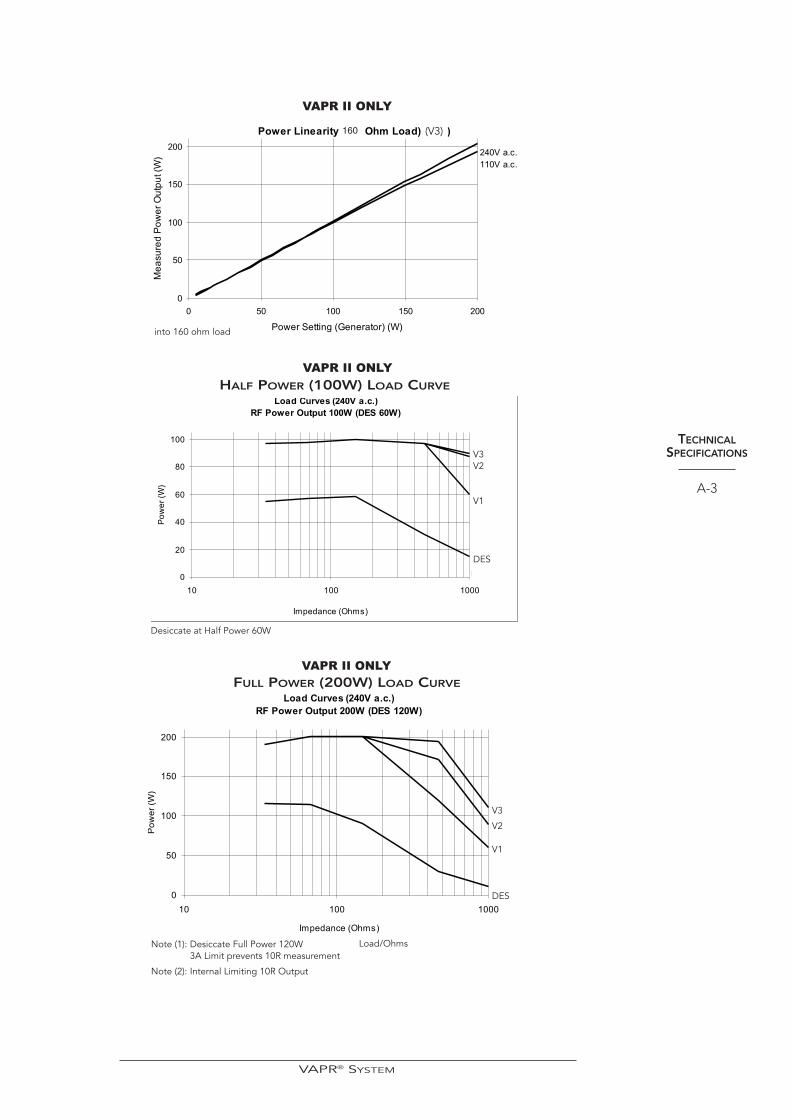
Power Maximum power 200 watts into 160 ohms.
Max Voltage:
V1 254V RMSV2 307V RMSV3 340V RMSBV1 307V RMSBV2 340V RMSDesiccate 120V RMSVAPR TC Desiccate 100V RMS
NOTE: The following load curves apply to the fundamental power delivery capability of the generatoralone. They do not imply a given power output for any given electrode and cable configurationwhen used with the generator. Each accessory will self-impose an upper set power limit for thegenerator, the value of which will be equal to or below the maxium power delivery capabilityof the generator.
TECHNICALSPECIFICATIONS
A-2
VAPR® SYSTEM
TECHNICALSPECIFICATIONS
A-3
into 160 ohm load
(V3)160
Desiccate at Half Power 60W
V3V2
V1
DES
HALF POWER (100W) LOAD CURVE
Load/OhmsNote (1): Desiccate Full Power 120W 3A Limit prevents 10R measurement
Note (2): Internal Limiting 10R Output
V3
V2
V1
DES
FULL POWER (200W) LOAD CURVE
VAPR II ONLY
VAPR II ONLY
VAPR II ONLY
VAPR® SYSTEM

TECHNICALSPECIFICATIONS
A-4
V3
V2
V1
DES
OUTPUT WAVEFORM AND CHARACTERISTICS
(VAPR 3 ONLY)
Waveform The RF output is a variable amplitude sinusoidwaveform varying between approximately340kHz and 450kHz, corresponding to minimumand maximum load impedance respectively.
Crest Factor V1, V2, V3, BV1, BV2 and DesiccateA nominal crest factor of 1.4 for all outputs.
Power Maximum power 260 watts into 160 ohms.
Max Voltage:
V1 254V RMSV2 307V RMSV3 340V RMSBV1 307V RMSBV2 340V RMSDesiccate 120V RMSVAPR TC Desiccate 100V RMS
NOTE: The following load curves apply to the fundamental power delivery capability of the generatoralone. They do not imply a given power output for any given electrode and cable configurationwhen used with the generator. Each accessory will self-impose an upper set power limit for thegenerator, the value of which will be equal to or below the maxium power delivery capabilityof the generator.
VAPR II AND VAPR 3
VAPR® SYSTEM

TECHNICALSPECIFICATIONS
A-5FULL POWER (260W) LOAD CURVE
LOAD CURVE (240 a.c) RF POWER OUTPUT 260W (DES 120W)
POWER LINEARITY (160 ohm) V3
VAPR 3 ONLY
VAPR 3 ONLY
LOAD CURVE (240V a.c) RF POWER OUTPUT 130W (DES 60W)
HALF POWER (130W) LOAD CURVE
VAPR 3 ONLY
V3
V2
V1
DES
V3
V2
V1
DES
(W)
VAPR® SYSTEM

TECHNICALSPECIFICATIONS
A-6
Attention, consult accompanying documents.
Non-ionizing radiation.
This equipment intentionally emits RF energy duringactivation.
Defibrillator-proof type BF equipment.
This equipment provides a degree of protection againstelectric shock to TYPE B as defined in IEC 60601-1. Thisequipment has an F type applied part capable ofwithstanding the effects of defibrillator discharge.
This symbol indicates the conductor that may be usedto provide potential equalization between theequipment and the installations busbar.
VAPR® SYSTEM

Appendix B
WARRANTY
The manufacturer warrants the products listed below to be free from defects inmaterial and workmanship under normal use and service for the period(s) set forthbelow. The manufacturer’s obligation under this warranty is limited to the repair orreplacement, at its sole option, of any product, or part thereof, which has beenreturned to it or its Distributor within the applicable time period shown below afterdelivery of the product to the original purchaser, and which examination discloses, tothe manufacturer’s satisfaction, that the product is defective. This warranty does notapply to any product, or part thereof, which has been repaired or altered outside themanufacturer’s factory in a way so as, in the manufacturer’s judgment, to affect itsstability or reliability, or which has been subjected to misuse, neglect or accident.
The warranty periods for the components of the Mitek Electrosurgical System are asfollows:
Generator One year from shipment date
Footswitch 90 days from shipment date
Reusable Accessories 30 days from shipment date
Electrodes Single-use only
THIS WARRANTY IS IN LIEU OF ALL OTHER WARRANTIES, EXPRESSED ORIMPLIED, INCLUDING, WITHOUT LIMITATION, THE WARRANTIES OFMERCHANTABILITY AND FITNESS FOR A PARTICULAR PURPOSE, AND OF ALLOTHER OBLIGATIONS OR LIABILITIES ON THE PART OF THE MANUFACTURER.The manufacturer neither assumes nor authorizes any other person to assume for itany other liability in connection with the sale or use of any of the manufacturer’sproducts, notwithstanding any other provision herein or in any other document orcommunication. The manufacturer’s liability with respect to this agreement andproducts sold hereunder shall be limited to the aggregate purchase price for thegoods sold by the manufacturer to the customer. There are no warranties whichextend beyond the terms hereof. The manufacturer shall not be liable hereunder orelsewhere in connection with the sale of this product, for any indirect, punitive orconsequential damages or lost profits. If the tamper proof seal on the Generator isbroken, this warranty will be voided.
This warranty and the right and obligations hereunder shall be construed under andgoverned by the laws of the Commonwealth of Massachusetts, USA.
The manufacturer reserves the right to make changes in equipment built and/or soldby it at any time without incurring any obligation to make the same or similarchanges on equipment previously built and/or sold by them.
The products listed above are exclusively manufactured for Mitek in the UnitedKingdom.
WARRANTY
B-1
Manufactured for DePuy Mitek by: GYRUS Medical
EU Representative:DePuy International LtdSt Anthony's RoadBeestonLeeds, LS11 8DTUKTel: +44 113 270 0461 Fax: +44 113 272 4101
DePuy Mitek, Inc.325 Paramount Drive Raynham, MA 02767, USA1-800-356-4835
VAPR® SYSTEM