Valvistor Proportional Flow Control Cartridge Valves - …pub/@eaton/@hyd/documents/co… ·...
16
Valvistor ® Proportional Flow Control Cartridge Valves CVCS-**-HFV, 10 Series, Covers CVI-**-HFV-A/B, 10 Series, Inserts 350 bar Up to 2160 L/min
Transcript of Valvistor Proportional Flow Control Cartridge Valves - …pub/@eaton/@hyd/documents/co… ·...

Valvistor® Proportional Flow ControlCartridge Valves
CVCS-**-HFV, 10 Series, CoversCVI-**-HFV-A/B, 10 Series, Inserts
350 barUp to 2160 L/min

1 EATON Valvistor Cartridge Valve V-VLPO-MC011-E April 2009
Table of Contents
General Description ........................................................................................................................................................................ 2
Valvistor Technology ........................................................................................................................................................................ 2
Basic characteristics ....................................................................................................................................................................... 2
Features and Benefits ..................................................................................................................................................................... 3
Functional Symbols ......................................................................................................................................................................... 4
Model Codes .................................................................................................................................................................................. 5
Operating Data ............................................................................................................................................................................... 6
Pivot Valve Electrical Data ............................................................................................................................................................... 6
Flow Pressure Drop Charts............................................................................................................................................................. 7
Pressure Drop ................................................................................................................................................................................. 9
Hydraulic Fluids .............................................................................................................................................................................10
Filtration Requirements .................................................................................................................................................................10
Temperature Limits ........................................................................................................................................................................10
Mounting Bolts and Assembly Torques .........................................................................................................................................11
Seal Kits .........................................................................................................................................................................................11
Ordering Procedure .......................................................................................................................................................................11
Installation Dimensions .................................................................................................................................................................12
Valvistor Line Extension (High performance and OBE options) .....................................................................................................13
Released Part Numbers .................................................................................................................................................................14

EATON Valvistor Cartridge Valve V-VLPO-MC011-E April 2009 2
General DescriptionEaton’s Vickers® HFV (Hydraulic Feedback Valvistor®) range of slip-in cartridge valves uses a self-regulating hydraulic design for the control of flow rate by a current-controlled PWM sig-nal. The design achieves servo-type control of the main pop-pet without using an electrical feedback transducer.
The construction and features of these valves open up a wide range of applications with hydraulic cylinders and motors. Such applications include ie casting, deep drawn presses, injection molding, container handling, shovel loaders, forestry and dump trucks. With the addition of HFV valves to the established ISO 7368 (DIN 24342) cartridge valves, Eaton has further enhanced an already comprehensive range.
Valvistor TechnologyIn “Valvistor” designs a main poppet amplifies a small flow through the pilot circuit, comparable to a transistor. Thus the name “Valvistor”, derived from “valve” and “transis-tor”. Figures 1 and 2 show the construction of proportional throttles to ISO 7368. In both cases a Vickers type KTG4V-3S proportional valve is used as the pilot control valve. Hydraulic position feedback is obtained by providing the main poppet with a longitudinal slot (5) in its cylindrical surface. This slot, together with a metering edge inside the sleeve, formsa variable orifice between the inlet of the valve and the vol-ume above the main poppet (3). When the valve is closed and the main poppet is seated, the variable orifice area is almost closed.
Figure 1Construction for flow direction A to B; poppet in the closed(no flow) condition. (Note: For flow A-B, poppet drilled from A.)
Figure 2Construction for flow direction B to A; poppet partially open. (Note: For flow B-A, poppet drilled from B.)
Basic CharacteristicsNominal Sizes:
ISO 7368 DIN 2434206 NG1608 NG2509 NG3210 NG4011 NG5012 NG63
Maximum operating pressure ......................350 bar (5000 psi)Flow ratings ............................. up to 2160 L/min (571 USgpm)
Catalog data based on pilot valve KTG4V-3S-EN427.
As the main poppet opens, the variable orifice area increases. The slot is a part of one leg of a hydraulic bridge circuit and provides an internal position feedback. With the pilot throttle valve closed (figure 1), there is no pilot flow through the closed-off slot in the seated poppet. The pressure above the main poppet (3) is equal to the pressure at the valve inlet (1), due to the controlled small opening at the variable orifice. As the upper area of the poppet is greater than the area facing the inlet (1), the poppet is held against its seat (6) by a force proportional to the difference between valve inlet and outlet pressures.
Opening the pilot throttle valve (figure 2) lowers the pressure in volume (3) allowing the main poppet to move off its seat. As this occurs the slot passes the metering edge (7), open-ing the variable orifice and allowing flow through the pilot circuit. Initially the flow through the pilot valve equals the flow through the slot plus the volume displaced by the open-ing movement of the main poppet. The main poppet moves upwards until the pressure drops across the slot and the pilot effects a force balance on the poppet. The poppet is then held in a steady-state condition with equal flow across the slot and the pilot.
If the flow through the pilot valve is reduced (by reducing the command current to the solenoid), the force balance of the main poppet is again disturbed and the main poppet moves downwards reducing the slot area and decreasing flow to the upper chamber until the force balance is restored. Thus by controlling flow through the pilot valve, the main poppet can be controlled in any position from fully closed to fully open. In this manner a very simple, effective servo-control of the main poppet is obtained. If the outlet pressure exceeds inlet pres-sure when the pilot valve is closed, the main poppet allows reverse flow (see CVCS model code). The main valve function is determined by the type of pilot fitted.
If pressure compensation is added to the pilot stage, the complete valve is pressure compensated. If a pilot relief valve is fitted, the main stage operates as a relief valve. As the pilot flow is returned to the valve outlet (i.e. no “drain” connec-tion) the valve is energy efficient. Therefore the position of the main poppet is controlled by a closed-loop system with a variable orifice in the poppet acting as the internal position feedback element. The command signal in this feedback sys-tem is pilot flow, as set at the proportional pilot throttle valve (4).
65
4
1
2
Inlet A
3
Outlet B
7
1
2
3
4
Outlet A
Inlet B
7
6
65
4
1
2
Inlet A
3
Outlet B
7
1
2
3
4
Outlet A
Inlet B
7
6

3 EATON Valvistor Cartridge Valve V-VLPO-MC011-E April 2009
Features and BenefitsThe HFV range with its simplicity, cost effectiveness and per-formance level can be applied in almost all applications from high performance industrial areas such as injection molding to those applications just requiring proportional functionality.
The data in this catalog is based on the specially developed proportional pilot KTG4V-3S-60-EN427. The functional flexibil-ity of the Valvistor may be extended by the use of different pilots. Contact Eaton for application assistance.
In addition, the HFV range offers:
Unequalled simplicity No inner electrical feedback loop and associated electronicsTwo models: for flow direction A to B or B to A Provides system design options and flexibilityFree flow in reverse direction Provides system design options and flexibilityPoppet valve construction Provides tight shut-off and load holdingInternal pilot flow Simple installation and energy efficientVery fast response Provides the system designer with high dynamic acceleration/velocity/deceleration profiles for demanding performance requirements such as: •Cylinderpositioncontrolincludinglift/lower •Rotaryactuatordynamiccontrol •VelocityprofilecontrolSmooth closing and opening Shock-free start-up and shut-off allow high velocities to be maintained for longer periods, thus reducing cycle timesLow hysteresis 8% to 1% depending on pilot valve usedIntegral feedback Internal hydraulic feedback provides effective, low-cost position control of main poppetRepeatability Provides repeatable and accurate actuator velocity to a given operator command inputElectrical operation Current-controlledPWMsignalPressure compensation CanbeachievedbypressurecompensatingpilotstageonlyCost-effective design Provides multiple functions such as pressure compensation, flow control and reverse free flow check valveOptional manual override Pin designCompatible with antiwear hydraulic oils and phosphate esters (non alkyl) Flexible application for broad range of installationsElectrical connections DIN or conduit box ProvidesdesignflexibilitytomeetOEMoruserpreference
Inherent benefits of Eaton cartridge valve technology are applicable to the Valvistor range.

EATON Valvistor Cartridge Valve V-VLPO-MC011-E April 2009 4
Functional Symbols Valvistor® Proportional Throttle Valves
Complete valve assembly comprises insert, cover and proportional solenoid operated pilot valve (pilot valve to be specified and ordered separately).
Models without free reverse flow capa-bilityUse cover type CVCS-**-HFV*-W-*2(9)-1*
Simplified symbol
Models with free reverse flow capabilityUse cover type CVCS-**-HFV*-*2(9)-1*Note: Omit W from model code position 6
Simplified symbol
Direction of controlled flowA to BUse insert type CVI-**-HFV-20-A-***-1*
B to AUse insert type CVI-**-HFV-20-B-***-1*
A
B
X Y
A BP T
Z1 Z2
P T
BA
A
B
X Y
A BP T
Z1 Z2
P T
BA
A
B
X Y
A BP T
Z1 Z2
P T
BA
A
B
X Y
A BP T
Z1 Z2
P T
BA
AP2AP1 AP2AP1
PAPA
Z2
B
AY
Z2
B
AY
Z2
B
AY
Z2
B
AY

5 EATON Valvistor Cartridge Valve V-VLPO-MC011-E April 2009
Model Codes Valvistor® Proportional Throttle Valves
(F3-) CVI - ** - HFV - 20 - * - *** - 1*
(F3-) CVCS - ** - HFV - * - * - * 2 (9) - 1*
1 Seal MaterialF3 - Seals for phosphate esters or chlorinated hydro-carbons. Omit for all other fluid types. 2 Model
CVI - Cartridge valve insert 3 Nominal size to ISO
7368 (DIN 24342)16 - 06 (NG16)25 - 08 (NG25)32 - 09 (NG32)40 - 10 (NG40)50 - 11 (NG50)63 - 12 (NG63)
1 Fluid compatibilityF3 - Seals for phosphate esters or chlorinated hydro-carbons. Omit for all other fluid types. 2 Model
CVI - Cartridge valve cover toISO 7368 3 Nominal size to ISO 7368 (DIN 24342)16 - 06 (NG16)25 - 08 (NG25)32 - 09 (NG32)40 - 10 (NG40)50 - 11 (NG50)63 - 12 (NG63)
7 Flow capacity at Δp = 10 bar (145 psi)
Size/Flow Direction Code L/min USgpm
16A 21 210 5516B 21 210 5525A 40 405 10725B 32 320 10732A 63 630 16632B 63 630 16640A 90 900 23840B 81 900 23850A 130 1305 34550B 130 1305 34563A 216 2160 57163B 216 2160 571
7 Thread/seal combina-tionB - G (BSPF) threads for gage ports; metric threads for orifices (only available when ‘‘3’’ speci- fied at position 5 )S - SAE O-ring gage; inch threads for orifices (only available when ‘‘1’’ speci- fied at position 5 )
1
1 42
2
3 9
3 5 64
6 75 8
7 8
10
4 Flow direction HFV - Hydraulic feedback, Valvistor
5 Area ratio 20 - 1:2 area ratio
6 Flow direction A - For flow A to B B - For flow B to A
4 TypeHFV - Hydraulic feedback, Valvistor
5 Size 3 pilot valve mount-ing bolts1 - Imperial threads3 - Metric threads
6 Control optionW - Mainstage Valvistor with-out free reverse flow.Omit for standard mainstage Valvistor with free reverse flow capability
8 Seals 2 - Inch O-ring seals to ISO 3601 9 Mounting bolts Sizes 16-40 only9 - Metric mounting bolts supplied as standard when ‘‘B’’ (BSPF threads) specified at position 7 Omit for sizes 50 and 63 10 Design number, 1* series Subject to change. Installa-tion dimensions unaltered for design numbers 10 to 19.
Valvistor Throttle Covers (Suitable for flows A to B and B to A)
Pilot ValveFor operation with 12V control system:KTG4V-3S2B 08N-(V)M-*** ****(1)G5-60-EN427
For operation with 24V control system:KTG4V-3S2B 08N-(V)M-*** ****(1)H5-60-EN427
For full technical details of this valve including types of electrical connec-tions, see Eaton’s Vickers Slip-in Car-tridge Valve Catalog.

EATON Valvistor Cartridge Valve V-VLPO-MC011-E April 2009 6
Operating Data Data is typical with fluid at 36 cSt (168 SUS) and 50C (122F).
Maximum pressure 350 bar (5000 psi)Flow ratings Seemodelcode(CVI)Controlled flow characteristics See graphs on pages 7 and 8Pressure drop, free return flow See graphs on page 9Dynamic performance: 06 08 09 10 11 12 Step input ▲ response at Δp = 10 bar (145 psi) (NG16) (NG25) (NG32) (NG40) (NG50) (NG63) Opening time (ms) 50 85 130 240 280 340 Closingtime(ms) 40 60 85 130 200 300 Hysteresis ▲ <8% <8% <8% <8% <8% <8% Repeatability▲ <3% <3% <3% <3% <3% <3%Area ratio (all sizes) 2:1Hydraulic fluids See page 11Temperature limits See page 11Filtration requirements See page 11Mounting bolts and assembly torques See page 12Seal kits See page 12Mass See page 12▲ Data quoted with KTG4V-3S---60-EN427 as pilot valve, driven by EEA-PAM-523-A-32 (Economic Performance) ▲ For standard & high performance and On-Board-Electronics (OBE) options, see “Valvistor line extension“ on page 13.
Pilot Valve Electrical Data Full performance data and model code breakdown can be found in Eaton’s Vickers Slip-in Cartridge Valve Catalog.
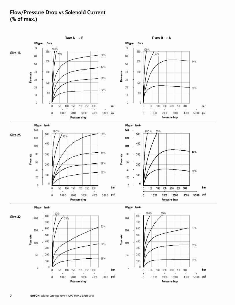
Type KTG4V-3S---60-EN427(denotesspecialspool)Max. current at 500C (122F) Coiltype G H 3.2A 1.6ACoil resistance at 200C (68F) 1.8 ohms 7.3 ohmsCoil inductance at 1000 Hz 7.5 mH 29 mHRelative duty factor Continuousrating(ED=100%)Electrical protection with plugs fitted correctly IEC947classIP65Recommended amplifier EEA-PAM-523-A-32▲ For standard & high performance and On-Board-Electronics (OBE) options, see “Valvistor line extension“ on page 13. Performance CharacteristicsThe graphs on the following two pages show typical flow characteristics for different values of input current to pilot valve plot-ted against flow rate and valve pressure drop. They are based on a standard HFV insert and cover with a KTG4V-3S---EN427 pilot valve. A minimum pressure drop of 5 bar (72 psi) is recommended. Higher pressure drops result in improved control.
7 EATON Valvistor Cartridge Valve V-VLPO-MC011-E April 2009
44%
38%
0
000500010 400030002000
50 100 150 200 250 300
Pressure drop
500
400
300
200
100
0
140
120
100
80
60
40
20
0
USgpm L/minFl
ow ra
te
Flow/Pressure Drop vs Solenoid Current (% of max.) 2.
Size 16
Size 25
Size 32
Flow A B wolFB AUSgpm
70
L/min
60
50
40
30
0
10
20
250
200
0
50
100
150
0
000500010 400030002000
50%
38%
44%
32%
50 100 150 200 250 300
100%
75%
bar bar
psi
Pressure drop
Flow
rate
100%
%001%001
100% 100%
50%
75%
75%
75%
75%
44%
38%
50%
38%
44%
32%
50%
38%
63%
44%
38%
50%
38%
63%
0
000500010 400030002000
50 100 150 200 250 300
psi
bar
psi
bar
psi
bar
psi
bar
psi
Pressure drop
0
000500010 400030002000
50 100 150 200 250 300
0
000500010 400030002000
50 100 150 200 250 300
Pressure drop
0
000500010 400030002000
50 100 150 200 250 300
Pressure drop
0
000500010 400030002000
50 100 150 200 250 300
Pressure drop
USgpm
70
L/min
60
50
40
30
0
10
20
250
200
0
50
100
150
Flow
rate
500
400
300
200
100
0
140
120
100
80
60
40
20
0
200
0
50
100
150
800
700
0
100
200
300
400
500
600
USgpm L/min
USgpm L/min
Flow
rate
Flow
rate
500
400
300
200
100
0
140
120
100
80
60
40
20
0
200
0
50
100
150
800
700
0
100
200
300
400
500
600
USgpm L/min
Flow
rate
Flow/Pressure Drop vs Solenoid Current (% of max.)

EATON Valvistor Cartridge Valve V-VLPO-MC011-E April 2009 8
200
Size 40
Size 50
Size 63
Flow A B Flow B A
0
000500010 400030002000
50 100 150 200 250 300
psiPressure drop
0
000500010 400030002000
50 100 150 200 250 300
psiPressure drop
0
000500010 400030002000
50 100 150 200 250 300
psiPressure drop
0
000500010 400030002000
50 100 150 200 250 300
psiPressure drop
0
000500010 400030002000
50 100 150 200 250 300
psi
bar
bar
bar bar
bar
bar
Pressure drop
0
000500010 400030002000
50 100 150 200 250 300
psiPressure drop
USgpm L/min
400
300
0
100
200
250
1250
0
500
1000
750
Flow
rate
82%
63%
75%
57%
100% 94%1500
USgpm L/min
400
300
0
100
200
250
1250
0
500
1000
750
Flow
rate
1500
75%
69%
57%
100%94% 82%
USgpm L/min
500
400
300
0
100
200
2000
1750
0
500
1000
1500
Flow
rate
USgpm L/min
Flow
rate
USgpm L/min
Flow
rate
USgpm
700
L/min
600
500
400
300
0
100
200
2500
2000
0
500
1000
1500
Flow
rate100% 88%
75%
63%
50%
38%
100% 88%
75%
63%
50%
38%
100% 82%
75%
69%
63%
50%
100%82%
75%
69%
57%
50%
1250
750
250
500
400
300
0
100
2000
1750
0
500
1000
1500
1250
750
250
88%700
600
500
400
300
0
100
200
2500
2000
0
500
1000
1500
Flow/Pressure Drop vs Solenoid Current (% of max.)

9 EATON Valvistor Cartridge Valve V-VLPO-MC011-E April 2009
Size 16
Size 32
Size 50
Size 25
Size 40
Size 63
Pres
sure
dro
p
Flow rate
psi bar
L/min
USgpm
8070605040302010
0 0
1
2
3
4
56
0 50 100 150 200
0 10 20 30 40 50L/min
USgpm
0 100 200 300 400
0 20 40 60 80 100 120
psi bar
80
60
40
20
0 0
1
2
8
4
5
6
10
9
3
7
140
120
100
Pres
sure
dro
p
Flow rate
L/min
USgpm
0 300100 400200
0 150 200100 25050
psi bar
80
60
40
20
0 0
1
2
8
4
5
6
10
9
3
7
140
120
100
Pres
sure
dro
p
Flow rate
L/min
USgpm
0 250 500 750 1000
0 50 100 150 200 250
psi bar
80
60
40
20
0 0
1
2
8
4
5
6
10
9
3
7
140
120
100
Pres
sure
dro
p
Flow rate
L/min
USgpm
0 500 1000 1500 2000
0 100 200 300 400 500 600
psi bar
80
60
40
20
0 0
1
2
8
4
5
6
10
9
3
7
140
120
100
Pres
sure
dro
p
Flow rate
L/min
USgpm
0 500 1000 1500
0 100 200 300 400
psi bar
80
60
40
20
0 0
1
2
8
4
5
6
10
9
3
7
140
120
100
Pres
sure
dro
p
Flow rate
450
500 600 700 800
2500
Pressure Drops - Free Return Flow

EATON Valvistor Cartridge Valve V-VLPO-MC011-E April 2009 10
Hydraulic FluidsAll cartridge valves can be used with antiwear hydraulic oils, and certain low viscosity fluids. Add prefix “F3” to model designations when phosphate esters (not alkyl-based) or chlo-rinated hydrocarbons are to be used. The extreme viscosity range is from 500 to 5 cSt (2270 to 42 SUS) but the recom-mended running range is from 54 to 13 cSt (245 to 70 SUS).
Filtration RequirementsEssential information on the correct methods for treating hydraulic fluid is included in the Eaton’s Vickers publication 561 “Vickers Guide to Systemic Contamination Control”, avail-able from your local Eaton distributor.
Recommendations on filtration and the selection of products to control fluid condition are also included in Eaton’s Vickers publication 561.
Temperature LimitsAmbient min ............................................................– 20C (–4F)Ambient max .......................................................+70C (+158F) Fluid temperatures
Petroleum oil Wateroil containing
Min. –20C +10C (–4F) (+50F)Max. +80C +54C (+176F) (+130F) Recommended cleanliness levels using petroleum oil under common conditions is based on the highest fluid pressure levels in the system. In referencing the table below, the bold-ed numbers highlight the recommended cleanliness level for Valvistor proportional throttles.
Fluids other than petroleum, severe service cycles or temper-ature extremes are cause for adjustment of these cleanliness codes. See Eaton’s Vickers publication 561 for exact details.
Recommended Fluid Cleanliness Level (ISO Code)
System Pressure Level System Pressure Level System Pressure Level Product 69 bar (1000 psi) 138 bar (2000 psi) 210+ bar (3000 psi)
VanePumps–Fixed 20/18/15 19/17/14 18/16/13VanePumps–Variable 18/16/14 17/15/13PistonPumps–Fixed 19/17/15 18/16/14 17/15/13PistonPumps–Variable 18/16/14 17/15/13 16/14/12DirectionalValves 20/18/15 20/18/15 19/17/14Pressure/FlowControlValves 19/17/14 19/17/14 19/17/14ServoValves 16/14/11 16/14/11 16/13/10Proportional Valves 17/15/12 17/15/12 15/13/11Cylinders 20/18/15 20/18/15 20/18/15VaneMotors 20/18/15 19/17/14 18/16/13Axial Piston Pumps 19/17/14 18/16/13 17/15/12RadialPistonPumps 20/18/14 19/17/13 18/16/13
11 EATON Valvistor Cartridge Valve V-VLPO-MC011-E April 2009
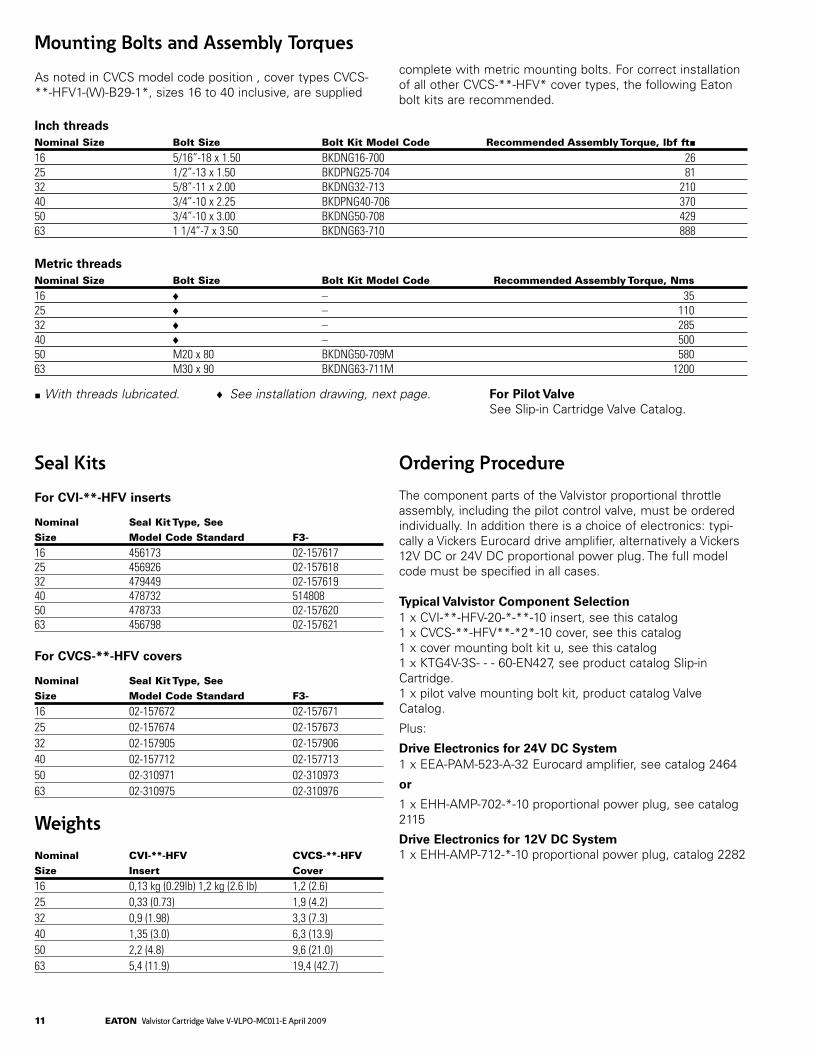
Seal Kits
For CVI-**-HFV inserts
Nominal Seal Kit Type, SeeSize Model Code Standard F3-
16 456173 02-15761725 456926 02-15761832 479449 02-15761940 478732 51480850 478733 02-15762063 456798 02-157621 For CVCS-**-HFV covers
Nominal Seal Kit Type, SeeSize Model Code Standard F3-
16 02-157672 02-15767125 02-157674 02-15767332 02-157905 02-15790640 02-157712 02-15771350 02-310971 02-31097363 02-310975 02-310976 WeightsNominal CVI-**-HFV CVCS-**-HFVSize Insert Cover
16 0,13 kg (0.29lb) 1,2 kg (2.6 lb) 1,2 (2.6)25 0,33 (0.73) 1,9 (4.2)32 0,9 (1.98) 3,3 (7.3)40 1,35 (3.0) 6,3 (13.9)50 2,2 (4.8) 9,6 (21.0)63 5,4 (11.9) 19,4 (42.7)
Ordering Procedure
The component parts of the Valvistor proportional throttle assembly, including the pilot control valve, must be orderedindividually. In addition there is a choice of electronics: typi-cally a Vickers Eurocard drive amplifier, alternatively a Vickers 12V DC or 24V DC proportional power plug. The full model code must be specified in all cases.
Typical Valvistor Component Selection1 x CVI-**-HFV-20-*-**-10 insert, see this catalog1 x CVCS-**-HFV**-*2*-10 cover, see this catalog1 x cover mounting bolt kit u, see this catalog1 x KTG4V-3S- - - 60-EN427, see product catalog Slip-in Cartridge.1 x pilot valve mounting bolt kit, product catalog Valve Catalog.
Plus:
Drive Electronics for 24V DC System1 x EEA-PAM-523-A-32 Eurocard amplifier, see catalog 2464
or
1 x EHH-AMP-702-*-10 proportional power plug, see catalog 2115
Drive Electronics for 12V DC System1 x EHH-AMP-712-*-10 proportional power plug, catalog 2282
Mounting Bolts and Assembly Torques
As noted in CVCS model code position , cover types CVCS-**-HFV1-(W)-B29-1*, sizes 16 to 40 inclusive, are supplied
complete with metric mounting bolts. For correct installation of all other CVCS-**-HFV* cover types, the following Eaton bolt kits are recommended.
Inch threadsNominal Size Bolt Size Bolt Kit Model Code Recommended Assembly Torque, lbf ft■16 5/16”-18 x 1.50 BKDNG16-700 2625 1/2”-13 x 1.50 BKDPNG25-704 8132 5/8”-11 x 2.00 BKDNG32-713 21040 3/4”-10 x 2.25 BKDPNG40-706 37050 3/4”-10 x 3.00 BKDNG50-708 42963 1 1/4”-7 x 3.50 BKDNG63-710 888 Metric threadsNominal Size Bolt Size Bolt Kit Model Code Recommended Assembly Torque, Nms
16 ♦ – 3525 ♦ – 11032 ♦ – 28540 ♦ – 50050 M20x80 BKDNG50-709M 58063 M30x90 BKDNG63-711M 1200
■ With threads lubricated. ♦ See installation drawing, next page. For Pilot Valve See Slip-in Cartridge Valve Catalog.

EATON Valvistor Cartridge Valve V-VLPO-MC011-E April 2009 12
Installation Dimensions in mm (inches)
Port Z1
H
4 holes thru Ø KMetric mounting bolts, Msupplied with sizes 16-40 onlywhen -B29- specifiedat model code positions and
3rd angleprojection
CVCS-**-HFV*
B
C
C
J
A E
A D
Port X
Port Z2
Port Y
Profile ofsize 16 only
Location pinDatum bolt hole forsize 03 mounting face
(CVCS-**-HFV*-W only)
T
P
S
G
89,6 (3.53)
5 6
G min. for removalof cover assembly
Valve A sq. B C max. D E max. G H J Ø K M SSize (K dia.) Mounting Bolts (supplied)
16 66,0 85,5 4,5 68,5 14,5 8,0 36,0 32,50 8,75/9,25 M8x50caphd.screw 48,0 (2.6) (3.36) (0.18) (2.7) (0.57) (0.32) (1.42) (1.28) (0.344/0.364) (1.89)25 86,0 – 3,5 88,5 13,5 10,5 25,0 20,75 13,75/14,25 M12x40caphd.screw 39,0 (3.38) (0.14) (3.5) (0.53) (0.42) (0.98) (0.82) (0.541/0.561) (1.54)32 102,5 – 3,5 104,5 13,5 13,0 30,0 21,50 17,75/18,25 M16x55caphd.screw 48,0 (4.0) (0.14) (4.2) (0.53) (0.52) (1.18) (0.85) (0.699/0.718) (1.89)40 126,0 – 2,0 128,5 11,0 15,0 35,0 21,50 21,75/22,25 M20x60caphd.screw 58,0 (5.0) (0.08) (5.1) (0.43) (0.59) (1.38) (0.85) (0.856/0.875) (2.28)50 142,5 – 4,5 145,0 0 18,0 42,0 21,50 21,75/22,25 – 68,0 (5.6) (0.18) (5.7) (0) (0.71) (1.66) (0.85) (0.856/0.875) (2.68)63 183,0 – 4,5 185,5 0 20,0 48,0 21,50 32,75/33,25 – 83,0 (7.2) (0.18) (7.3) (0) (0.79) (1.89) (0.85) (1.289/1.309) (3.27)

13 EATON Valvistor Cartridge Valve V-VLPO-MC011-E April 2009
High Performance Extended Configuration Extended Configurations
Pilot Valve Non-OBE Valve OBE Valve Model Code & Part Number KFTG4V-3-2B13N-Z-M-U-H7-10, 506834 KBFTG4V-3-2B13N-Z-M1-PE7-H7-11, 5996165-001 KBFTG4V-3-2B13N-Z-M2-PE7-H7-11, 5996350-001
Valvistor® Line ExtensionProportional Slip-in Cartridge Valve, Flow ControlK(B)TG4V-3 Pilot Stage K(B)FTG4V-3 Pilot Stage
Eaton’s Vickers® line is now extended with the addition of K(B)TG4V-3 and K(B)FTG4V-3 pilot stage proportional valves. The new features and benefits of the higher performance and on-board electronics (OBE) open up new applications and mar-kets. The valves piloted with K(B)FTG4V-3 offer performance that is close to conventional feedback valves. As its name implies, the Valvistor design has a main poppet valve that amplifies a low flow rate through the pilot circuit, similar to a transistor. This innovative design achieves servo-type control of the main poppet, without using an electrical main poppet position feedback transducer on the Slip-in cartridge valve.
Features and benefits of the new valves include:• Integralhydraulicfeedbackonmainstage—Closedloop, main-stage performance is achieved without using a main- stage LVDT.• Pilotstageselectedtomeetspecificrequirements—Cost- effective design results in design flexibility.• Pilotflowisdirectedtotheload—Higherflowefficiencyis achieved since the flow is not wasted to the tank.• IP65andIP67environmentalprotectionratedbestinclass —Morereliableperformanceinharshenvironments.• OnboardrampadjustmentonKBTGpilot.
Applications include injection and blow molding, rubber mold-ing, press, die-casting, offshore, civil engineering, marine, pri-mary metal, and mobile applications. The tables below showexisting Valvistor configurations and the new extended con-figurations with K(B) TG4V-3 and K(B)FTG4V-3 as pilot valves.
Step Response (ms) Open Close Open Close Delta P Tested 10 bar 10bar 10bar 10bar
NG16 51 33 35 25NG25 88 50 50 30NG32 135 71 70 45NG40 249 108 130 65NG50 290 167 170 100NG63 352 250 200 150Hysteresis 1% 1% 1% 1%
Notes Valvistor full flow reached at around 70% command input of K(B)F with 13N spool. For M2 version, the command input range is 4-12ma, valve is fully open at 4ma, and fully closed at 12ma.

EATON Valvistor Cartridge Valve V-VLPO-MC011-E April 2009 14
Standard Performance Extended Configuration Extended Configurations
Pilot Valve Non-OBE Valve OBE Valve Model Code & Part Number KTG4V-3-2B08N-M-U-H7-60-EN427, 02-398752 KBTG4V-3-2B08N-M1-PE7-H7-10-EN427, 02-398750 Other configurations available. KBTG4V-3-2B08N-M2-PE7-H7-10-EN427, 02-398751 Contact Eaton
Economical Solution Extended Configuration Extended Configurations
Pilot Valve Non-OBE Valve OBE Valve Model Code & Part Number KTG4V-3S-2B08N-M-U-H5-60-EN427, 02-154581 KBTG4V-3S-2B08N-M1-PE7-H5-10-EN427, 02-397168 Other configurations available. KBTG4V-3S-2B08N-M2-PE7-H5-10-EN427, 02-398753 Contact Eaton
Step Response (ms) Open Close Open Close Delta P Tested 10 bar 10 bar 10 bar 10 bar
NG16 50 40 38 24NG25 85 60 66 36NG32 130 85 101 51NG40 240 130 186 78NG50 280 200 217 120NG63 340 300 264 180Hysteresis <5 <5 <5 <5Notes:ForM2version,thecommandinputrangeis4-12ma,valveisfullyopenat4ma,andfullyclosedat12ma.
Released Part Numbers Model Code Assembly Number
CVCS-16-HFV1-S2-10 02-311552CVCS-16-HFV1-W-S2-10 02-312313CVCS-16-HFV3-B29-10 02-310565CVCS-16-HFV3-W-B29-10 02-312336CVCS-25-HFV1-S2-10 02-311553CVCS-25-HFV1-W-S2-10 02-312312CVCS-25-HFV3-B29-10 02-157809CVCS-25-HFV3-W-B29-10 02-157811CVCS-32-HFV1-S2-10 02-311554CVCS-32-HFV1-W-S2-10 02-312310CVCS-32-HFV3-B29-10 02-310641CVCS-32-HFV3-W-B29-10 02-312335CVCS-40-HFV1-S2-10 02-312311CVCS-40-HFV1-W-S2-10 02-312314CVCS-40-HFV3-B29-10 02-157212CVCS-40-HFV3-W-B29-10 02-312121CVCS-50-HFV1-S2-10 02-312103CVCS-50-HFV1-W-S2-10 02-312104CVCS-50-HFV3-B2-10 02-311957CVCS-50-HFV3-W-B2-10 02-311959CVCS-63-HFV1-S2-10 02-312106CVCS-63-HFV1-W-S2-10 02-312107CVCS-63-HFV3-B2-10 02-311958CVCS-63-HFV3-W-B2-10 02-311960
Model Code Assembly Number
F3-CVCS-16-HFV3-W-B29-10 02-358045F3-CVCS-25-HFV1-W-S2-10 02-333781F3-CVCS-25-HFV3-W-B29-10 02-319363F3-CVCS-32-HFV1-W-S2-10 02-312315F3-CVCS-40-HFV1-W-S2-10 02-353592F3-CVCS-50-HFV1-S2-10 02-325658F3-CVCS-50-HFV1-W-S2-10 02-395045
CVI-16-HFV-20-A-21-10 02-310564CVI-16-HFV-20-B-21-10 02-310563CVI-25-HFV-20-A-43-10 02-157670CVI-25-HFV-20-B-32-10 02-157741CVI-32-HFV-20-A-63-10 02-310643CVI-32-HFV-20-B-63-10 02-310642CVI-40-HFV-20-A-90-10 02-157234CVI-40-HFV-20-B-81-10 02-157233CVI-50-HFV-20-A-130-10 02-312101CVI-50-HFV-20-B-130-10 02-312102CVI-63-HFV-20-A-216-10 02-311063CVI-63-HFV-20-B-216-10 02-311062
Step Response (ms) Open Close Open Close Delta P Tested 10 bar 10 bar 10 bar 10 bar
NG16 50 40 38 24NG25 85 60 66 36NG32 130 85 101 51NG40 240 130 186 78NG50 280 200 217 120NG63 340 300 264 180Hysteresis <8% <8% <8% <8%Notes:ForM2version,thecommandinputrangeis4-12ma,valveisfullyopenat4ma,andfullyclosedat12ma.

EatonHydraulics Group USA14615LoneOakRoadEdenPrairie,MN55344USATel: 952-937-9800Fax: 952-294-7722www.eaton.com/hydraulics
EatonHydraulics Group EuropeRoutedelaLongeraie71110MorgesSwitzerlandTel:+41(0)218114600Fax:+41(0)218114601
EatonHydraulic Group Asia Pacific11thFloorHongKongNewWorldTower300HuaihaiZhongRoadShanghai 200021ChinaTel: 86-21-6387-9988Fax: 86-21-6335-3912
© 2009 Eaton CorporationAll rights reservedPrinted in USADocument No. V-VLPO-MC011-EApril 2009


![Cartridge Valves Technical Information Proportional Valves Quick … · 2020. 5. 19. · PSV12-NO SDC12-2 100 l/min [26 US gal/min] 260 bar [3770 psi] 11.27 Proportional Flow Controls](https://static.fdocuments.in/doc/165x107/612d59851ecc51586942224f/cartridge-valves-technical-information-proportional-valves-quick-2020-5-19.jpg)