Valve ampli er for proportional valves without electrical ...
36
Operating instructions RE 30232-B/08.2020 Replaces 04.2020 English Valve amplifier for proportional valves without electrical position feedback VT-MSPA Component series 2X HAD_8134
Transcript of Valve ampli er for proportional valves without electrical ...

Operating instructionsRE 30232-B/08.2020
Replaces 04.2020English
Valve amplifier for proportional valves without electrical position feedbackVT-MSPA Component series 2X
HAD_8134

The data specified only serve to describe the product. If information on the use of the product is given, it is only to be regarded as application examples and recommendations. Catalog information does not constitute warranted properties. The information given does not release the user from the obligation of own judgment and verification. Our products are subject to a natural process of wear and aging.
© Bosch Rexroth AG 2016. All rights reserved, also regarding any disposal, exploitation, reproduction, editing, distribution, as well as in the event of application for industrial property rights.
The cover shows an example configuration. The product supplied may differ from the solution shown here.
The original operating instructions were created in the German language.

RE 30232-B/08.2020, Valve amplifier VT-MSPA, Bosch Rexroth AG
3/36 Content
Content
1 About this documentation 51.1 Validity of the documentation 51.2 Required and supplementary documentation 51.3 Representation of information 51.3.1 Safety instructions 51.3.2 Symbols 61.3.3 Terms 61.3.4 Abbreviations used 62 Safety instructions 72.1 About this chapter 72.2 Intended use 72.3 Improper use 72.4 Qualification of personnel 82.5 General safety instructions 82.6 Product-specific safety instructions 92.7 Personal protective equipment 102.8 Operator‘s obligations 103 General information on damage to property and damage to the product 114 Scope of delivery 125 About this product 125.1 Identification of the product 126 Transport and storage 136.1 Storing electronic products 137 Installation 137.1 Required tools 147.2 Recommended accessories 147.3 Installation conditions 147.3.1 Place of installation 147.4 Installing und connecting the VT-MSPA...-2X 147.5 Connecting the supply voltage 157.5.1 Shielding 167.5.2 General notes on shielding 167.5.3 Connecting the individual contacts 177.5.4 Suppressing interference of the system 188 Commissioning 188.1 Block circuit diagram VT-MSPA1-2X 198.2 Block circuit diagram VT-MSPA2-2X 208.3 Operating and display elements 218.3.1 Status LEDs 218.3.2 Test jacks 228.4 Selecting the valve types 228.5 Menu 258.5.1 Menu structure 258.6 Parameter setting 26

4/36
Bosch Rexroth AG, Valve amplifier VT-MSPA, RE 30232-B/08.2020
8.6.1 Explanation of menu level “Standard Mode“ 278.6.2 Explanation of menu level “Expert Mode“ 278.7 Restoring the VT-MSPA...-2X to factory settings 299 Operation 3010 Maintenance and repair 3110.1 Cleaning and care 3110.2 Inspection and maintenance 3110.3 Repair 3111 Demounting and replacement 3211.1 Required tools 3211.2 Preparing demounting 3211.3 Demounting 3211.4 Preparations for storage and further use 3312 Disposal 3312.1 Environmental protection 3312.2 Return to Bosch Rexroth AG 3312.3 Packaging 3312.4 Materials used 3312.5 Recycling 3413 Extension and modification 3414 Troubleshooting 3414.1 How to proceed for troubleshooting 3415 Technical data 3516 Annex 3516.1 List of addresses 35

About this documentation 5/36
RE 30232-B/08.2020, Valve amplifier VT-MSPA, Bosch Rexroth AG
1 About this documentation
1.1 Validity of the documentationThis documentation is valid for valve amplifiers VT-MSPA1-2X and VT-MSPA2-2X from Bosch Rexroth. This documentation is intended for fitters, operators, service technicians, system operators and machine manufacturers.This documentation contains important information on the safe and appropriate installation, transport, commissioning, maintenance, operation, use, and removal of the product.
▶ Read this documentation thoroughly, especially Chapter 2 “Safety instructions“ and Chapter 3 “General notes on damage to property and damage to the product“, before working with the product.
1.2 Required and supplementary documentation ▶ The product must not be commissioned until you have been provided with the
documentation marked with the book symbol and you have understood and observed it.
Table 1: Required and supplementary documentation
1.3 Representation of informationIn order that this documentation allows you to work directly and safely with your product, standardized safety notes, symbols, terms, and abbreviations are used. For a better understanding, they are explained in the following sections.
1.3.1 Safety instructionsThis documentation contains safety notes in chapter 2.6 “Product-specific safety instructions“ and chapter 3 “General notes on damage to material and the product“ as well as before a sequence of activities or instructions for action, which involve the risk of personal injury or damage to equipment. The hazard avoidance measures described must be observed.
Safety instructions are structured as follows:
SIGNAL WORDType and source of danger!Consequences in case of non-compliance
▶ Hazard avoidance measures ▶ <Enumeration>
• Warning symbol:draws attention to a hazard • Signal word: identifies the degree of hazard
Title Document number Type of document
Order confirmation
Valve amplifier for proportional valves without electrical position feedback, VT-MSPA
30232 Data sheet

6/36 About this documentation
Bosch Rexroth AG, Valve amplifier VT-MSPA, RE 30232-B/08.2020
• Type and source of danger!: specifies the type and source of hazard • Consequences: describes the consequences in case of non-observance • Precaution: specifies how the hazardous situation can be prevented
Table 2: Hazard Classifications according to ANSI Z535.6-2011
Warning sign, signal word Meaning
DANGER Indicates a hazardous situation which, if not avoided, will certainly result in death or serious injury.
WARNINGIndicates a hazardous situation which, if not avoided, could result in death or serious injury.
CAUTIONIndicates a hazardous situation which, if not avoided, could result in minor or moderate injury.
NOTICE Damage to property: The product or the environment could be damaged.
1.3.2 SymbolsThe following symbols indicate notices which are not safety-relevant but increase the comprehensibility of the documentation.
Table 3: Meaning of the symbols
Symbol Meaning
If this information is disregarded, the product cannot be used or operated in an optimum manner.
▶ Individual, independent action
1. 2. 3.
Numbered instruction:The numbers indicate that the actions must be carried out one after the other.
1.3.3 TermsThe following designations are used in this documentation:
Table 4: Terms
Term MeaningElectronics Command value cards, amplifiers, and controls manufactured by Bosch
Rexroth
1.3.4 Abbreviations usedThe following abbreviations are used in this documentation:
Table 5: Abbreviations used
Abbreviation Meaning
ANSI American National Standards Institute
EMC Electromagnetic compatibility
FC Frequency converter
PELV Protective Extra Low Voltage

Safety instructions 7/36
RE 30232-B/08.2020, Valve amplifier VT-MSPA, Bosch Rexroth AG
2 Safety instructions
2.1 About this chapterElectronic devices from Bosch Rexroth are manufactured according to the generally accepted rules of technology. However, there is still a risk of personal injury and damage to property if you do not observe this chapter and the safety instructions in this documentation.
▶ Read this documentation completely and thoroughly before working with the product.
▶ Keep this documentation in a location where it is accessible to all users at all times.
▶ Always include the required documentation when you pass the product on to third parties.
2.2 Intended useThe products are electrical and electronic components.You may use the product as follows: • For operating proportional hydraulic valves without electrical position feedback • For applications as specified in technical data sheet RE 30232 • While adhering to the operating and ambient conditions according to data sheet RE 30232
• While adhering to the given performance limits • In the original condition, without damage • Repairs by customers are not permitted
The product is intended exclusively for professional use and not for private usage.Operation according to the intended use also implies that you have read and understood this documentation completely, especially chapter 2 “Safety instructions“.
2.3 Improper useAny use other than described in the section “Intended use” is considered as improper and is therefore not permitted.Bosch Rexroth AG does not assume any liability for damage caused by improper use. The user assumes all risks involved with improper use.Improper use includes, but is not limited to: • operating the electronics outside the specified performance limits and operating conditions, especially the prescribed ambient conditions;
• the use as safety-related part of controls in the sense of DIN EN ISO 13849. Functional safety must be realized by means of appropriate, additional components.
• use in potentially explosive atmospheres • improper transport • improper storing • lack of cleanliness during storage and assembly • incorrect installation

8/36 Safety instructions
Bosch Rexroth AG, Valve amplifier VT-MSPA, RE 30232-B/08.2020
2.4 Qualification of personnelThe activities described in this documentation require basic knowledge of electrics and hydraulics as well as knowledge of the associated technical terms. In order to ensure safe use, these activities may only be carried out by an expert in the respective field or an instructed person under the direction and supervision of an expert.Experts are those who are able to recognize potential hazards and apply the appropriate safety measures due to their professional training, knowledge and experience, as well as their understanding of the relevant conditions pertaining to the work to be undertaken. An expert must observe the relevant specific professional rules and have the necessary expert knowledge.With regard to electronic products, expertise means, for example: • Ability to read and completely understand circuit diagrams, • in particular, completely understanding the correlations regarding safety equipment and
• knowledge of the function and structure of electrical and electronic components.
Bosch Rexroth offers measures that support your qualification in specific fields. You can find an overview of training contents on the Internet at: http://www.boschrexroth.com
2.5 General safety instructions • Observe the valid regulations on accident prevention and environmental protection. • Observe the safety regulations and provisions of the country in which the product is used/applied.
• Exclusively use Bosch Rexroth products in technically perfect condition. • Observe all notices on the product. • Persons who install, commission, operate, demount or maintain Bosch Rexroth products must not consume any alcohol, drugs or pharmaceuticals that may affect their ability to respond.
• Only use original Bosch Rexroth accessories and spare parts in order to prevent any hazard to persons due to unsuitable spare parts.
• Comply with the technical data and environmental conditions specified in the product documentation.
• The installation or use of inappropriate products in safety-relevant applications could result in unintended operating states in the application which in turn could cause personal injuries and/or damage to property. Therefore, only use a product for safety-relevant applications if this use is expressly specified and permitted in the documentation of the product, e.g. in explosion protection zones or in safety-related parts of control systems (functional safety).
• You may commission the product only when it has been established that the final product (for example, a machine or system), in which the Bosch Rexroth product is installed, complies with national regulations, safety regulations and standards relevant for the application.

Safety instructions 9/36
RE 30232-B/08.2020, Valve amplifier VT-MSPA, Bosch Rexroth AG
2.6 Product-specific safety instructions
WARNINGHazardous movements!Risk of injury due to incorrect connection or incorrect activation of electrical and electronic devices and resulting unforeseeable machine movements.
▶ Observe safety in accordance with EN ISO 13849 or IEC 62061. ▶ If persons have to enter the hazard zone while the control is active, provide
superordinate monitoring functions or measures for personal safety. These measures must be provided according to the specific data of the system and on the basis of the risk and error analysis of the system manufacturer/user. In this connection, the safety provisions applied for the system must be taken into account.
▶ Failures and defects in the control current or the energy supply can result in uncontrolled machine movements.
▶ Electronics emit interference to other electronics within the permitted limit values and also react to interference. This can cause malfunction in the control process. Only use electronics below EMC limit values or provide appropriate shielding.
▶ Electrostatic processes, an inadequate grounding concept or missing equipotential bonding can lead to damage to the electronics and hence cause malfunction or uncontrolled movements of the machine. Ensure proper grounding and provide equipotential bonding.
▶ Using the product outside the specified IP protection class can result in short-circuit and malfunction and hence in uncontrolled machine movements. Therefore, use the product only within the IP protection class and in environments as specified in the data sheet.
▶ Provide safety functions for personal safety separately. Amplifiers, command value processing cards and control electronics themselves do not include safety functions for personal safety and are no safety-related components.
▶ Avoid contact with salt-laden environments and adhere to the ambient temperature given in the data sheet.
▶ In the event of an emergency, fault or other abnormalities, switch the system off and secure it against being switched on again.

10/36 Safety instructions
Bosch Rexroth AG, Valve amplifier VT-MSPA, RE 30232-B/08.2020
WARNINGHigh electrical voltage by incorrect connection!Danger to life, risk of injury due to electric shock.
▶ When carrying out any work, disconnect the relevant machine section from the power supply and protect it against being switched on again.
▶ Only connect devices, electrical components and cables which feature protective extra low voltage (PELV) to connections or terminals having voltages from 0 to 50 Volt.
▶ Only connect voltages and power circuits that feature safe isolation from dangerous voltages. Safe isolation can be achieved with isolation transformers, safe optocouplers or mains-free battery operation.
▶ Always connect all cables to the provided connections. Avoid open cables or contacts.
Lightning!Risk of uncontrolled machine movements.
▶ An inadequate grounding concept or missing equipotential bonding can lead to damage to the electronics. Provide for equipotential bonding of the device.
CAUTIONFault currents and short-circuits!Impairment of safety and malfunction.
▶ Keep the surroundings free from electrically conductive contamination (acids, bases, corrosive agents, salts, metal vapors, etc.) and do not expose the device to these substances. Generally rule out any deposits according to protection class IP.
2.7 Personal protective equipmentCheck determined personal protective equipment for completeness and protective effect and wear it (observe customer regulations and list of personal protective equipment).
2.8 Operator‘s obligationsThe operation of installations, systems and machines basically requires the implementation of a holistic IT security concept which is state-of-the-art in terms of technology. Accordingly, Bosch Rexroth products and their properties must be considered as components of installations, systems and machines for their holistic IT security concept.Unless otherwise documented, Bosch Rexroth products are designed for operation in local, physically and logically secured networks with access restrictions for authorized persons, and they are not classified according to IEC 62443-4-2.

General information on damage to property and damage to the product 11/36
RE 30232-B/08.2020, Valve amplifier VT-MSPA, Bosch Rexroth AG
3 General information on damage to property and damage to the product
The warranty only applies to the delivered configuration.Warranty claims will be rejected in the case of improper installation, commissioning and operation as well as in the case of use not in accordance with the intended purpose and/or improper handling.
NOTICEHigh voltage!The electronics may be damaged.
▶ Wire electronics from Bosch Rexroth only when these are disconnected from the power supply.
Wrong cables! Power loss, scorching of cable!Risk of damage to the product!
▶ Only use the cables specified in the data sheet with the respective cable cross-sections for electronic devices from Bosch Rexroth!
Radiated interference!Risk of malfunction.
▶ The distance to radio sources must be sufficiently large (>> 1 m). ▶ In the case of strongly fluctuating operating voltage, it may be necessary to use
an external smoothing capacitor in individual cases.
Emitted interference!Risk of affecting other devices.
▶ Use shielded signal and solenoids cables in order that EMC requirements are fulfilled.
Overloading!Risk of overloading and damage to the supply cable in the case of insufficient dimensioning and/or operation with several electrical devices.
▶ Provide current limitation by overload protection. ▶ Select an appropriate rating of power supply units and cables.
Short-circuit!Risk of overloading and damage of the supply cable in the case of defects of the electrical device.
▶ Provide current limitation by overload protection.
Impermissible temperature range!Risk of overheating. The devices can be thermally destroyed.
▶ Adhere to the specification in the data sheet.
Cables lying around!Risk of stumbling!
▶ Lay cables and lines so that they cannot be damaged and no one can trip over them.

12/36 Scope of delivery
Bosch Rexroth AG, Valve amplifier VT-MSPA, RE 30232-B/08.2020
4 Scope of deliveryInformation on the scope of delivery can be found in the shipping documents and data sheet RE 30232 of your Bosch Rexroth product:
▶ Check the scope of delivery for completeness and possible transport damage.
In case of complaints, please contact Bosch Rexroth AG, see chapter 16.1 “List of addresses“ on page 35.
5 About this productYou can find information on the product and its performance in the data sheet of your electronics. The data sheet and further information can be found at: www.boschrexroth.com/VT-MSPAx.
5.1 Identification of the productThe most important data of the product are given on a label or are printed directly at the side of the product.
1 Word mark2 Material short text3 Plant4 QR code5 Date of manufacture6 Country of origin
7 Customer-specific data8 Serial number9 Material number10 Electrical data and protection
class
2 3
1
10
9 5
6
4
78

Transport and storage 13/36
RE 30232-B/08.2020, Valve amplifier VT-MSPA, Bosch Rexroth AG
6 Transport and storageThere are no special instructions for transporting electronic products. You must, however, observe the notes in Chapter 2 “Safety instructions” and comply with the ambient conditions for storage and transport which are detailed in the technical data sheet RE 30232.
6.1 Storing electronic productsProceed as follows in order to prepare electronics from Bosch Rexroth for storage and further use:
▶ Whenever possible, use the original packaging for storage. ▶ Observe the permissible storage temperature range specified in the data sheet. ▶ Protect the electronics from dust and humidity.
7 Installation
NOTICERisk of short-circuit!In the case of electronics with housing, water may condense within the housing!
▶ Let the electronics acclimate itself for several hours, as otherwise water may condense in the housing.
The electronics are provided with cooling slots According to the specified protection class, dirt and fluids may easily enter and cause malfunction and short-circuit! Reliable operation is thus no longer ensured.
▶ When working on the electronics, observe strictest cleanliness and make sure that no fluids will enter the housing.
Major potential differences!Risk of destruction of electronics by plugging or unplugging connectors under voltage.
▶ Switch off power supply to the relevant system part before installing the products or plugging or unplugging connectors.
Radiated interference!Risk of malfunction.
▶ The distance to radio sources must be sufficiently large (>> 1 m). ▶ Do not lay solenoid or signal cables near power cables. ▶ Shield command and actual value cables. Connect the shield to system ground
on both ends.

14/36 Installation
Bosch Rexroth AG, Valve amplifier VT-MSPA, RE 30232-B/08.2020
7.1 Required toolsA screwdriver (blade width 2.0 mm, blade thickness 0.4 mm) is required for connecting flexible cables to the terminals of the VT-MSPA...-2X. For commissioning we recommend that you use a multimeter (measuring lead with 2-mm connectors). Further tools are not required.
7.2 Recommended accessoriesFor the connection of the VT-MSPA...-2X we recommend the following accessories (Table 6). These accessories are not included in the scope of the supply, but have to be ordered separately:
Table 6: Accessories
Designation Material no.Shield kit for installation with shielded cables (SERVICE PACKAGE VT-HMC...-1X/M...SCHIR&*ET)
R961011117
7.3 Installation conditions ▶ When installing the amplifier, strictly adhere to the ambient conditions specified
in data sheet RE 30232. ▶ The housing of the VT-MSPA...-2X features protection class IP20. Requirements
that exceed type of protection IP20 have to be ruled out. Avoid contact of the VT-MSPA...-2X with hydraulic fluids, acids, bases, corrosive agents, salts, metal vapors, solvents, etc.
7.3.1 Place of installationElectronics from Bosch Rexroth are intended for installation in control cabinets. Outdoor installation is not permitted.
7.4 Installing und connecting the VT-MSPA...-2XThe dimensions of valve amplifier VT-MSPA...-2 are given in data sheet RE 30232. The installation orientation is vertical. Observe the required mounting distances: • The distance to covers and walls must be at least 2 cm. • At ambient temperatures above 50 °C, provide a minimum distance of 1 cm to the next assembly.
• By snapping the housing of the VT-MSPA...-2X on a conductive and earthed mounting rail, the earth connection is established with the rear wall of the control cabinet. This constitutes HF grounding of the VT-MSPA...-2X.
• Do not use any silicone-containing sealants, adhesives or insulating agents. • Ensure maintenance-friendly installation, i.e. simple access to the connection lines. Ensure free access to the connection side.
• Lay cables and lines so that they cannot be damaged and no one can trip over them.
Install the VT-MSPA...-2X as follows on a DIN mounting rail in the control cabinet:1. Disconnect the relevant system part from the power supply.2. Snap the back panel of the VT-MSPA...-2X carefully into position on the DIN
mounting rail. Mechanical contact points on the rear panel of the VT-MSPA...-2X ensure firm seating on the DIN mounting rail, and the housing is connected to the grounding system of the control cabinet.

Installation 15/36
RE 30232-B/08.2020, Valve amplifier VT-MSPA, Bosch Rexroth AG
Fig. 1: Mounting the VT-MSPA...-2X on a DIN mounting rail
Should the spring-loaded latch not snap in automatically, it can be released using a screwdriver (see Fig. 1 on the right). After having positioned the latch, let it spring back to the snapped-in position.Observe the following when connecting the VT-MSPA...-2X:
▶ For mounting, observe the notes on applicable standards and operating conditions in data sheet RE 30232.
▶ Do not use connectors with free-wheeling diodes or LED lamps for connecting solenoid cables to the valve!
▶ Use low-capacitance cables. ▶ Whenever possible, execute cable connections without intermediate terminals. ▶ Install sensor cables separately. ▶ When sources of electromagnetic disturbance are used (e.g. frequency
converter), malfunction may occur. Avoid the installation of the VT-MSPA...-2X in the direct vicinity to sources of disturbance.
▶ The distance to aerial lines, radio sources and radar equipment must be at least 1 m.
▶ Do not lay signal cables near power cables. ▶ The system ground is an essential, integral part of EMC protection of the
VT-MSPA...-2X. Here, interference, which is transported to the VT-MSPA...-2X via data and voltage supply cables, is dissipated. This function can only be ensured, if the system ground itself does not inject interference into the control electronics.
7.5 Connecting the supply voltage1. Disconnect the relevant system part from the power supply.2. Inspect all cables for intactness.3. Connect the signal and solenoid cables according to your circuit diagram to the
relevant terminals of the VT-MSPA...-2X .4. Connect the supply voltage and check the presence of voltage by switching on.

16/36 Installation
Bosch Rexroth AG, Valve amplifier VT-MSPA, RE 30232-B/08.2020
7.5.1 ShieldingFor digital inputs and outputs as well as for the command value and the actual value the permissible cable length of unshielded cables is 30 m. In the case of greater lengths use shielded cables with a copper braid shield. Connect the cable shield on both ends and on a large area to the system ground. For connection of the cable shield to the VT-MSPA..-2X we recommend the use of our shield kit, see Fig. 2 (accessories, see chapter7.2, page 14).As solenoid cables you may use unshielded cables.
Fig. 2: Shielding of the VT-MSPA...2X
7.5.2 General notes on shielding ▶ Install signal and power cables as far away from each other as possible and do
not install them in parallel. ▶ Do not route signal cables through strong magnetic fields. ▶ Lay signal lines as continuously as possible. If intermediate terminals are
required, the shield must be dealt with separately. Install power cables consisting of two individual wires (e.g. voltage supply) as twisted cables.
▶ Cables should only have the number of wires actually required. If this is impossible, connect the wires with each other and connect them to ground on one side in the control cabinet.
Installation 17/36
RE 30232-B/08.2020, Valve amplifier VT-MSPA, Bosch Rexroth AG
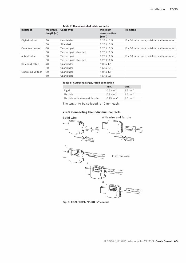
Table 7: Recommended cable variants
Table 8: Clamping range, rated connection
Min. Max.Rigid 0.2 mm² 2.5 mm²
Flexible 0.2 mm² 2.5 mm²
Flexible with wire end ferrule 0.25 mm² 2.5 mm²
The length to be stripped is 10 mm each.
7.5.3 Connecting the individual contacts
Fig. 3: XG20/XG21: “PUSH-IN“ contact
Interface Maximum length [m]
Cable type Minimum cross-section [mm2]
Remarks
Digital in/out 30 Unshielded 0.25 to 2.5 For 30 m or more, shielded cable required
50 Shielded 0.25 to 2.5
Command value 30 Twisted pair 0.25 to 2.5 For 30 m or more, shielded cable required
50 Twisted pair, shielded 0.25 to 2.5
Actual value 30 Twisted pair 0.25 to 2.5 For 30 m or more, shielded cable required
50 Twisted pair, shielded 0.25 to 2.5
Solenoid cable 20 Unshielded 1.0 to 1.5
50 Unshielded 1.5 to 2.5
Operating voltage 20 Unshielded 1.0 to 1.5
50 Unshielded 1.5 to 2.5
Solid wire With wire end ferrule
Flexible wire
1.
2.
3.

18/36 Commissioning
Bosch Rexroth AG, Valve amplifier VT-MSPA, RE 30232-B/08.2020
7.5.4 Suppressing interference of the systemShould interference occur in conjunction with signals of the electronics, inspect the interference suppression of other electrical components, e.g. as follows:
Possible causes of faults
Switched inductance DC: anti-parallel free-wheeling diode across actuator winding
AC: type-related R/C combination over actuator winding.
Electric motors R/C combination from each motor winding to earth.
Frequency converter Inlet filter in the voltage supply of the frequency converter
Motor control lines shielded and installed separately from other cables and/or output filter for motor cables.
Extensive contact of the frequency converter housing to the rear wall of the control cabinet
8 Commissioning
NOTICEUncontrolled plugging and unplugging of connectors!The device might be destroyed.
▶ Before plugging or unplugging connectors into or from the device, disconnect the device from the power supply or de-energize it reliably! Damage to the device caused by incorrect handling is not covered by the warranty!
▶ Observe the protection class, the voltage supply and the environmental conditions according to data sheet RE 30232.
For commissioning we recommend using a multimeter.

Commissioning 19/36
RE 30232-B/08.2020, Valve amplifier VT-MSPA, Bosch Rexroth AG
8.1 Block circuit diagram VT-MSPA1-2X
XH1
X2A
XH2
X2A
B
XH1
V
1 2 10956 1211
Zw-1
(1)
(2)
(5)
(11) (12)
(10)
(9.1
)
(7)
(6)
(8)
(14)
(13)
(15)
(4)
(3)
43
U
U0V
+24V
+U
KBA
tt
tt
tt
t
tt
I A –
I B
I B
t
KBB
KBB
MO -U
UU(
I) UU
UU
UU
+In -InDI
-Out
+Out
Gx
y
PWM
PID
BS
G
(9.2
)BSG
GS
b
Enable
Enab
le
Logic
Actu
al v
alue
Sup
ply
vol
tage
Com
man
d
valu
e
Dig
ital
input
Rea
dy f
or
oper
atio
n
Test
jack
Cab
le b
reak
1 Power supply unit 2 Differential amplifier 3 Command value summator
4 Zero point adjustment 5 Inversion 6 Simple ramp
7 4-quadrant ramp 8 Command value attenuator 9 Characteristic curve generator
10 Current regulator 11 Clock pulse generator 12 Output stage
13 Enable or inversion or ramp off or 4Q ramp
14 Switching logic/error detection 15 Digital output

20/36 Commissioning
Bosch Rexroth AG, Valve amplifier VT-MSPA, RE 30232-B/08.2020
8.2 Block circuit diagram VT-MSPA2-2X
XH1
X2A
XH2
X2A
XH2
A
B
XH1
V
1 2 10956 1211
Zw-1
(1)
(2)
(5)
(11)(12)
(10)
(12)
(10)
(9)
(9)
(7)
(6)
(8)
(14)
(13)
(15)
(4)
(3)
8 437U
U0V
+24V
+U
KBA
tt
tt
tt
t
tt
I A
I A –
I B
I B
t
KBB
KBA
KBB
MO -U
UU(
I) UU
UU
a b
UU
UU
+In -InDI
-Out
+Out
Gx
y
BS
GPW
MPI
D
PWM
PID
BS
G
Enable
Enab
le
Logic
Actu
al
valu
e
Sup
ply
vo
ltag
e
Com
man
d
valu
e
Dig
ital
input
Rea
dy f
or
oper
atio
n
Test
jack
Cab
le b
reak
Cab
le b
reak
Enable
1 Power supply unit 2 Differential amplifier 3 Command value summator
4 Zero point adjustment 5 Inversion 6 Simple ramp
7 4-quadrant ramp 8 Command value attenuator 9 Characteristic curve generator
10 Current regulator 11 Clock pulse generator 12 Output stage
13 Enable or inversion or ramp off or 4Q ramp
14 Switching logic/error detection 15 Digital output

Commissioning 21/36
RE 30232-B/08.2020, Valve amplifier VT-MSPA, Bosch Rexroth AG
8.3 Operating and display elements
Fig. 4: Operating and display elements
No. Meaning1 Status LEDs
Indicate the current operational state, menu levels and erroneous states
2 SET keyEditing of the selected parameters, selection of the operating modes, selection of the “Expert Mode“
3 Keys + / -Selection of parameters and setting of parameter values
4 Rotary switchSelection of the valve type
5 Test jacks
8.3.1 Status LEDsPermanently on
Flashing
Flickering
OFF
DI Digital (enable) input
t Ramp
Z/B Command value zero point / biasing current
G Command value attenuator
S Command value step height
Ready for operation
1st quadrant (positive command value, increasing)
2nd quadrant (positive command value, falling)
3rd quadrant (negative command value, increasing)
4th quadrant (negative command value, falling)
4
85
1
6
2
7
3
129 10 11
Set
tZ/BGS
I
v
T
valve
0 09 98 87 76 65 54 4
3 32 21 1
MSPA
1
1
2
3
5
Rexroth
4
DI
4
85
1
6
2
7
3
129 10 11
Set
tZ/BGS
IB IA
v
T
valve
0 09 98 87 76 65 54 4
3 32 21 1
MSPA
2
RexrothDI
Blinking code
Description of LED indicator lamps

22/36 Commissioning
Bosch Rexroth AG, Valve amplifier VT-MSPA, RE 30232-B/08.2020
8.3.2 Test jacksIB Actual current in solenoid B (VT-MSPA2-2X), I with VT-MSPA1-2X
IA Actual current in solenoid A (VT-MSPA2-2X)
⊥ Reference potential
v Internal command value or set value
8.4 Selecting the valve typesWhen setting a valve, the operator generally must ensure that no command value and no enable is applied to the VT-MSPAx-2X!
The desired valve type has to be selected by means of the two rotary switches, see Fig. 4 item 4. The left-hand rotary switch sets the tens place, the right-hand rotary switch the units place of the item. While you make the settings, test jack “v“ outputs the selected rotary switch position as a voltage value in 100-mV increments.The following valve types are available.
VT-MSPA1-2X Standard Expert
Rotary switchposition
Valve type(one solenoid)
t Z G 4Q t1 t2 t3 t4 GB GA SB SA B f Inv DIn
0-0 No valid valve – – – – – – – – – – – – – – – -
0-1 4WRA6...-2X ● ● ● ● ● ● – – ● – ● – – ● – ●0-2 4WRA10...-2X ● ● ● ● ● ● – – ● – ● – – ● – ●0-3 4WRZ...-7X ● ● ● ● ● ● – – ● – ● – – ● – ●0-4 3DREP6...-2X ● ● ● ● ● ● – – ● – ● – – ● – ●0-5 4WRPH6...-2X (SO855) ● ● ● ● ● ● ● ● ● ● ● ● – ● ● ●0-6 DBEP6...-1X ● ● ● ● ● ● – – ● – ● – – ● – ●0-7 DBET-6X...G24... ● ● ● ● ● ● – – – – – – – ● – ●0-8 DBET-6X...G24-8... ● ● ● ● ● ● – – – – – – – ● – ●0-9 DBETX-1X...G24-25... ● ● ● ● ● ● – – – – – – – ● – ●1-0 DBETX-1X...G24-8... ● ● ● ● ● ● – – – – – – – ● – ●1-1 (Z)DBE6-2X... ● ● ● ● ● ● – – – – – – – ● – ●1-2 DBEM10...-7X...G24... ● ● ● ● ● ● – – – – – – – ● – ●1-3 DBEM10...-7X...G24-8... ● ● ● ● ● ● – – – – – – – ● – ●1-4 DBEM20...-7X...G24... ● ● ● ● ● ● – – – – – – – ● – ●1-5 DBEM20...-7X...G24-8... ● ● ● ● ● ● – – – – – – – ● – ●1-6 DBEM30...-7X...G24... ● ● ● ● ● ● – – – – – – – ● – ●
Indicator lamps Operational state Display mode Meaning
LED DI “digital input“ (yellow)
Normal operation Permanently ON/OFF Status of digital input
Setup Flashing Standard setup active
Setup OFF Expert setup active
Setup ON/blinking/flickering Expert setup: Setting of enable input
LED “ready” (red/green)
Normal operation Permanently on green Module ready for operation
Normal operation Permanently on red Error
Normal operation and setup Blinking red/green Valve number changed (but not confirmed)
Normal operation and setup Blinking red Invalid valve number
Normal operation OFF Module not ready for operation
Setup Flashing green Expert setup active

Commissioning 23/36
RE 30232-B/08.2020, Valve amplifier VT-MSPA, Bosch Rexroth AG
VT-MSPA1-2X Standard Expert
Rotary switchposition
Valve type(one solenoid)
t Z G 4Q t1 t2 t3 t4 GB GA SB SA B f Inv DIn
1-7 DBEM30...-7X...G24-8... ● ● ● ● ● ● – – – – – – – ● – ●1-8 (Z)DRE6...-1X... ● ● ● ● ● ● – – – – – – – ● – ●1-9 ZDRE10...-2X...G24... ● ● ● ● ● ● – – – – – – – ● – ●2-0 ZDRE10...-2X...G24-8... ● ● ● ● ● ● – – – – – – – ● – ●2-1 DRE...10...-6X...G24... ● ● ● ● ● ● – – – – – – – ● – ●2-2 DRE...10...-6X...G24-8... ● ● ● ● ● ● – – – – – – – ● – ●2-3 DRE...20...-6X...G24... ● ● ● ● ● ● – – – – – – – ● – ●2-4 DRE...20...-6X...G24-8... ● ● ● ● ● ● – – – – – – – ● – ●2-5 DRE...30...-6X...G24... ● ● ● ● ● ● – – – – – – – ● – ●2-6 DRE.30...-6X...G24-8... ● ● ● ● ● ● – – – – – – – ● – ●2-7 3DRE...-7X...G24... ● ● ● ● ● ● – – – – – – – ● – ●2-8 3DRE...-7X...G24-8... ● ● ● ● ● ● – – – – – – – ● – ●2-9 3FREX6...-1X...G24-25... ● ● ● ● ● ● – – – – – – – ● – ●3-0 3FREX10...-1X...G24-25... ● ● ● ● ● ● – – – – – – – ● – ●3-1 3DREP6...-2X... (SO674) ● ● ● ● ● ● – – ● – ● – ● ● – ●3-2 Z3DRE10..-1X…G24… 1) ● ● ● ● ● ● – – – – – – – ● – ●3-3 DBE6X-1X…G24-25… 1) ● ● ● ● ● ● – – – – – – – ● – ●3-4 DBE6X-1X…G24-8… 1) ● ● ● ● ● ● – – – – – – – ● – ●3-5 DRE6X-1X...G24-8… 1) ● ● ● ● ● ● – – – – – – – ● – ●3-6 DBET-1X...HG24-8… 1) ● ● ● ● ● ● – – – – – – – ● – ●3-7 Pump control 1 (0.7 A)
EP2 (A7VO)● ● ● ● ● ● – – ● – ● – ● ● – ●
3-8 Pump control 2 (0.6 A)ED72 (A10VSO/31)ER72 (A10VSO/31)
● ● ● ● ● ● – – ● – ● – ● ● – ●
3-9 Pump control 3 (0.6 A) EP2 (A10VSO/52, 53)EK2 (A10VSO/52, 53)L4 (A15VSO...) E2 (A15VSO...) EP2,6 (A6VM)
● ● ● ● ● ● – – ● – ● – ● ● – ●
4-0 DBE10Z-1X...G24-8.. 1) ● ● ● ● ● ● – – – – – – – ● – ●4-1 DRE10Z-1X…G24-8… 1) ● ● ● ● ● ● – – – – – – – ● – ●4-2 (Z)3DRE6...-2X/...G24... 2) ● ● ● ● ● ● – – – – – – – ● – ●4-3 (Z)3DRE6...-2X/...G24-8... 2) ● ● ● ● ● ● – – – – – – – ● – ●9-6 Universal (0.8 A) ● ● ● ● ● ● – – ● – ● – ● ● – ●9-7 Universal (1.6 A) ● ● ● ● ● ● – – ● – ● – ● ● – ●9-8 Universal (2.5 A) ● ● ● ● ● ● – – ● – ● – ● ● – ●Rest No valve selected – – – – – – – – – – – – – – – –
1) Available as of series 21 (VT-MSPA1-21...)2) Available as of series 22 (VT-MSPA1-22...)

24/36 Commissioning
Bosch Rexroth AG, Valve amplifier VT-MSPA, RE 30232-B/08.2020
VT-MSPA2-2X Standard Expert
Rotary switchposition
Valve type(two solenoids)
t Z G 4Q t1 t2 t3 t4 GB GA SB SA B f Inv DIn
0-0 no valve – – – – – – – – – – – – – – –
0-1 4WRA6...-2X ● ● ● ● ● ● ● ● ● ● ● ● ● ● ● ●0-2 4WRA10...-2X ● ● ● ● ● ● ● ● ● ● ● ● ● ● ● ●0-3 4WRZ...-7X ● ● ● ● ● ● ● ● ● ● ● ● ● ● ● ●0-4 3DREP6...-2X ● ● ● ● ● ● ● ● ● ● ● ● ● ● ● ●0-5 3DREP6...-2X (SO674) ● ● ● ● ● ● ● ● ● ● ● ● ● ● ● ●0-6 DBEP6...-1X ● ● ● ● ● ● ● ● ● ● ● ● ● ● ● ●
0-7 ... 3-6 – – – – – – – – – – – – – – – – –
3-7 Pump control 1 (0.74 A)EP (A4CSG)
● ● ● ● ● ● ● ● ● ● ● ● ● ● ● ●
3-8 --- 3-9 ‒ – – – – – – – – – – – – – – – –
9-6 Universal (0.8 A) ● ● ● ● ● ● ● ● ● ● ● ● ● ● ● ●9-7 Universal (1.6 A) ● ● ● ● ● ● ● ● ● ● ● ● ● ● ● ●9-8 Universal (2.5 A) ● ● ● ● ● ● ● ● ● ● ● ● ● ● ● ●
If no valve type is selected, the LEDs signal the status shown on the left. The yellow LEDs rotate clockwise in pairs.
The “ready” LED blinks red/green, if the valve number saved last and the current rotary switch position do not match! The amplifier is active and utilizes the parameters of the valve type saved last. Remedy: If you wish to change the valve, remove the command value and the enable, press key [Set] > 1 sec and accept the new valve type. If the rotary switch position was changed accidentally, reset it to the original valve number. → The “ready” LED is lit green.
In both cases, check the actually connected valve!
Whenever a valve is changed, all changeable parameters are reset to factory settings!
tZ/BGS
DI

Commissioning 25/36
RE 30232-B/08.2020, Valve amplifier VT-MSPA, Bosch Rexroth AG
8.5 Menu
8.5.1 Menu structure
Fig. 5: Menu structure
4
85
1
6
2
7
3
129 10 11
Set
tZ/BGS
IB IA
v
T
VS
0 09 98 87 76 65 54 4
3 32 21 1
MSPA
tZ/BGS
t
GS
tZ/BGS
tZ/BGS
tZ/BGS
tZ/BGS
Set+-
Set+-
Set+-
Set+-
Set+-
Set+-
Set+-
Set+-
Set+-
Set+-
Set+-
Set+- Set
+-
Set+-
Set+-
+Set
-
RexrothDI
Z/B
DIDI
DI
DI
DIDI
Command value zero point / biasing current Z/B
Run
> 1 sec
Editable parameter level
Simple ramp t Ramp time
Zero point
Command value attenuator G
Command value maximum
Expert mode
Standard mode
> 1 sec
> 1 sec
26/36 Commissioning
Bosch Rexroth AG, Valve amplifier VT-MSPA, RE 30232-B/08.2020
The menu structure and operation of the “Expert Mode” corresponds to that of the “Standard Mode“. The parameters in the “Expert Mode“ can be found in chapter 8.6.2 „Explanation of menu level “Expert Mode““.
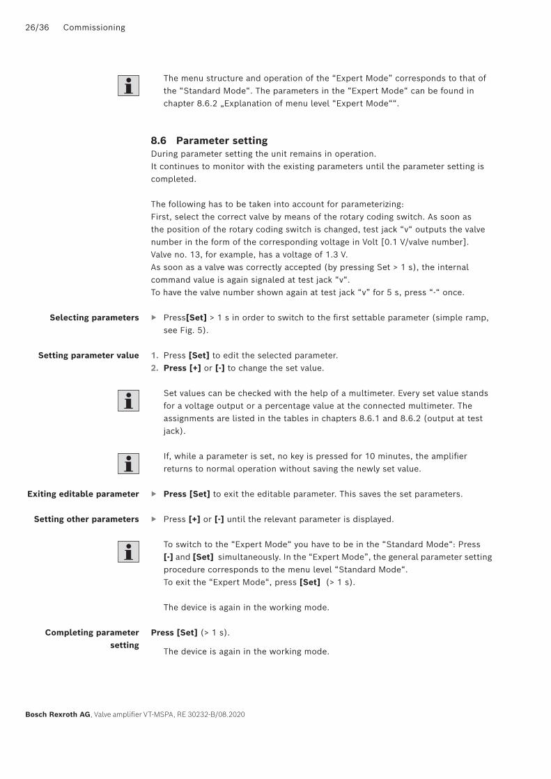
8.6 Parameter settingDuring parameter setting the unit remains in operation.It continues to monitor with the existing parameters until the parameter setting is completed.
The following has to be taken into account for parameterizing:First, select the correct valve by means of the rotary coding switch. As soon as the position of the rotary coding switch is changed, test jack “v“ outputs the valve number in the form of the corresponding voltage in Volt [0.1 V/valve number].Valve no. 13, for example, has a voltage of 1.3 V.As soon as a valve was correctly accepted (by pressing Set > 1 s), the internal command value is again signaled at test jack “v“.To have the valve number shown again at test jack “v” for 5 s, press “-“ once.
▶ Press[Set] > 1 s in order to switch to the first settable parameter (simple ramp, see Fig. 5).
1. Press [Set] to edit the selected parameter.2. Press [+] or [-] to change the set value.
Set values can be checked with the help of a multimeter. Every set value stands for a voltage output or a percentage value at the connected multimeter. The assignments are listed in the tables in chapters 8.6.1 and 8.6.2 (output at test jack).
If, while a parameter is set, no key is pressed for 10 minutes, the amplifier returns to normal operation without saving the newly set value.
▶ Press [Set] to exit the editable parameter. This saves the set parameters.
▶ Press [+] or [-] until the relevant parameter is displayed.
To switch to the “Expert Mode“ you have to be in the “Standard Mode“: Press [-] and [Set] simultaneously. In the “Expert Mode”, the general parameter setting procedure corresponds to the menu level “Standard Mode“. To exit the “Expert Mode“, press [Set] (> 1 s).
The device is again in the working mode.
Press [Set] (> 1 s).
The device is again in the working mode.
Selecting parameters
Setting parameter value
Exiting editable parameter
Setting other parameters
Completing parameter setting

Commissioning 27/36
RE 30232-B/08.2020, Valve amplifier VT-MSPA, Bosch Rexroth AG
8.6.1 Explanation of menu level “Standard Mode“The order in which the parameters below are listed corresponds to the order on the device. LED “ready“ lights green, LED “DI“ flashes yellow.
8.6.2 Explanation of menu level “Expert Mode“The order in which the parameters below are listed corresponds to the order on the device. Depending on the selected valve type, individual functions may not be available and are skipped in the selection of functions. See chapter 8.4“Selecting the valve types” on page 22. LED “ready“ flashes green.
Parameter LED indicator lamps
Description Editable parameter
Output at test jack v
Simple ramp tt
Z/BGS
DI
tt t
tt
Ramp time 0/10 ms...1000 ms:0/10 mV...1.00 V (1 s/V)
1 s...5 s:1.0 V...5.0 V (1 s/V)
5 s ... 30 sU = 0.2 V/s * t + 4 V
Command value zero point/biasing current Z/B t
Z/BGS
DI
ZZero point 0...±10 %:
0...±1 V (0.1 V/%)
Command value attenuator G t
Z/BGS
DI
x
y GCommand value maximum
70...110 %:0.70 V...1.10 V
Ramp function tt
Z/BGS
DIt t
t tt
ON/OFF Simple ramp ON: +1 V Ramp OFF: 0 V4Q ramp ON: +4 V
Parameter LEDindicator lamps
Description Editable parameter
Output at test jack v
Simple ramp tt
Z/BGS
DI
tt t
tt
Ramp time 0/10 ms...1000 ms:0/10 mV...1.00 V (1 s/V)
1 s...5 s:1.0 V...5.0 V (1 s/V)
5 s ... 30 sU = 0.2 V/s * t + 4 V
Command value zero point Z/B t
Z/BGS
DIZ
Zero point 0...±10 %:0...±1 V (0.1 V/%)
Command value attenuator G t
Z/BGS
DI
x
y GCommand value maximum
70...110 %:0.70 V...1.10 V

28/36 Commissioning
Bosch Rexroth AG, Valve amplifier VT-MSPA, RE 30232-B/08.2020
Parameter LED indicator lamps
Description Editable parameter
Output at test jack v
4Q ramp t1, 1st quadrant (positive command value, increasing)
tZ/BGS
DIt t
t tt
Ramp time 1st quadrant 1)
0/10 ms...1000 ms:0/10 mV...1.00 V (1 s/V)
1 s...5 s:1.0 V...5.0 V (1 s/V)
5 s... 30 s5.0 V ... 10 VU = 0.2 V/s * t + 4 V
4Q ramp t2, 2nd quadrant (positive command value, falling)
tZ/BGS
DIt t
t tt
Ramp time 2nd quadrant 1)
0/10 ms...1000 ms:0/10 mV...1.00 V (1 s/V)
1 s...5 s:1.0 V...5.0 V (1 s/V)
5 s... 30 s5.0 V ... 10 VU = 0.2 V/s * t + 4 V
4Q ramp t3, 3rd quadrant (negative command value, increasing)
tZ/BGS
DIt t
t tt
Ramp time 3rd quadrant 1)
0/10 ms...1000 ms:0/10 mV...1.00 V (1 s/V)
1 s...5 s:1.0 V...5.0 V (1 s/V)
5 s... 30 s5.0 V ... 10 VU = 0.2 V/s * t + 4 V
4Q ramp t4, 4th quadrant (negative command value, falling)
tZ/BGS
DIt t
t tt
Ramp time 4th quadrant 1)
0/10 ms...1000 ms:0/10 mV...1.00 V (1 s/V)
1 s...5 s:1.0 V...5.0 V (1 s/V)
5 s... 30 s5.0 V ... 10 VU = 0.2 V/s * t + 4 V
Command value attenuator GB for solenoid B (positive command value)
tZ/BGS
DI
GBCommand value attenuator Solenoid B
70...110 %:0.70 V...1.10 V
Command value attenuator GA for solenoid A (positive command value)
tZ/BGS
DI
AGCommand value attenuator Solenoid A
70...110 %:0.70 V...1.10 V
Step height SB, positive command value (solenoid B) t
Z/BGS
DI
B S
Step height, solenoid B
Biasing current...50 %:0...5.0 V
Step height SA, negative command value (solenoid A) t
Z/BGS
DI
AS
Step height, solenoid A
Biasing current...50 %:0...5.0 V
Commissioning 29/36
RE 30232-B/08.2020, Valve amplifier VT-MSPA, Bosch Rexroth AG
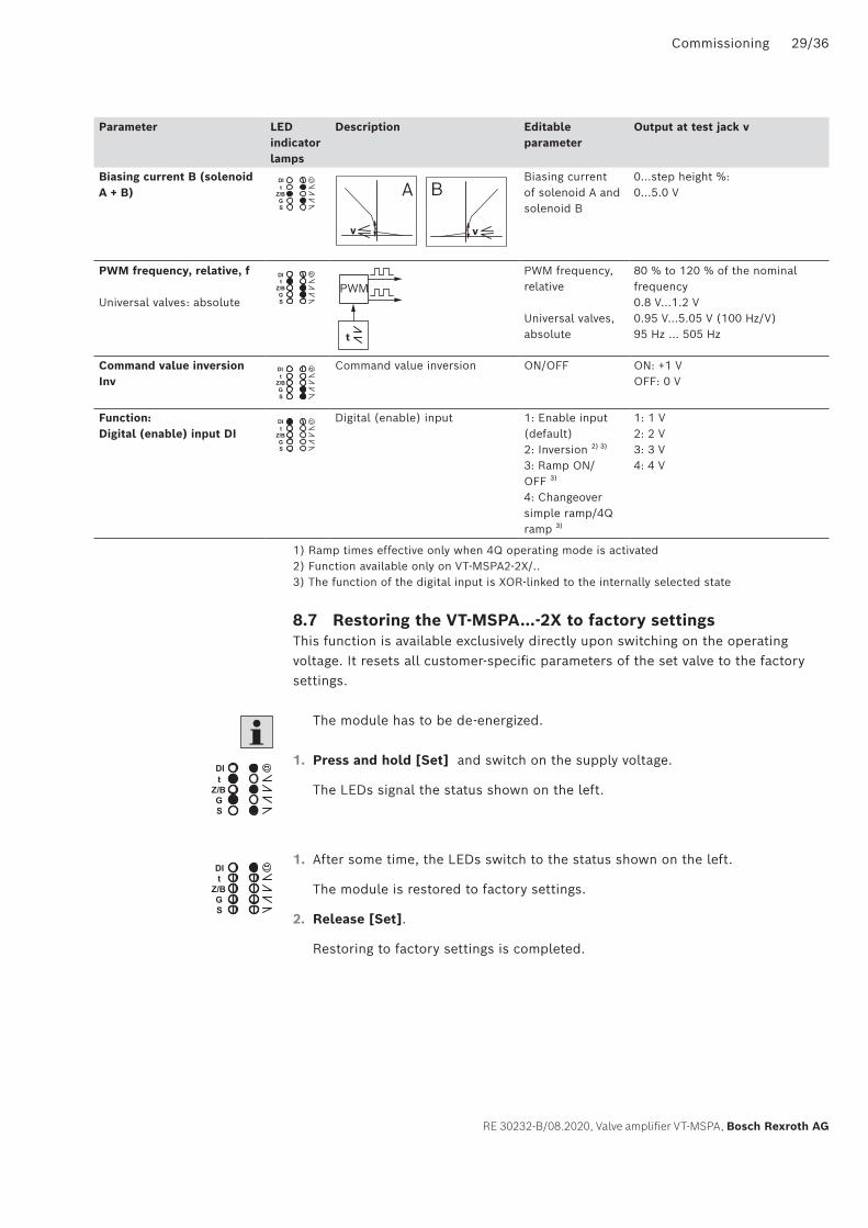
Parameter LED indicator lamps
Description Editable parameter
Output at test jack v
Biasing current B (solenoid A + B) t
Z/BGS
DI
BA
v v
Biasing current of solenoid A and solenoid B
0...step height %:0...5.0 V
PWM frequency, relative, f
Universal valves: absolute
tZ/BGS
DI
PWM
t
PWM frequency, relative
Universal valves, absolute
80 % to 120 % of the nominal frequency0.8 V...1.2 V0.95 V...5.05 V (100 Hz/V) 95 Hz ... 505 Hz
Command value inversion Inv t
GS
Z/B
DI Command value inversion ON/OFF ON: +1 VOFF: 0 V
Function: Digital (enable) input DI t
Z/BGS
DI Digital (enable) input 1: Enable input (default)2: Inversion 2) 3)
3: Ramp ON/OFF 3)
4: Changeover simple ramp/4Q ramp 3)
1: 1 V2: 2 V3: 3 V4: 4 V
1) Ramp times effective only when 4Q operating mode is activated 2) Function available only on VT-MSPA2-2X/.. 3) The function of the digital input is XOR-linked to the internally selected state
8.7 Restoring the VT-MSPA...-2X to factory settingsThis function is available exclusively directly upon switching on the operating voltage. It resets all customer-specific parameters of the set valve to the factory settings.
The module has to be de-energized.
1. Press and hold [Set] and switch on the supply voltage.
The LEDs signal the status shown on the left.
1. After some time, the LEDs switch to the status shown on the left.
The module is restored to factory settings.
2. Release [Set].
Restoring to factory settings is completed.
tZ/BGS
DI
tZ/BGS
DI

30/36 Operation
Bosch Rexroth AG, Valve amplifier VT-MSPA, RE 30232-B/08.2020
9 OperationShould a fault occur during operation, e.g. a power failure, the VT-MSPA...-2X can simply be switched on again without further measures and it is then ready for operation again.If the VT-MSPA..-2X.. detects an error, a reaction takes place according to the table below.
Error RemarkLED
(red/green) ready
LED (yellow) “digital input”
LEDs (yellow) “functions”
Solenoid output stages
Output “ready”
Output at test jack “v”
No error Permanently on green
Normal indication
Normal indication
Normal operation
Normal operation
Normal operation
Operating voltage UB too low
UB < UBmin Permanently on red
Normal indication
Normal indication
Switched off Switched off 7 V
Operating voltage UB too high
UB > UBmax Flashing green
Normal indication
Normal indication
Normal operation
Normal operation
Normal operation
Cable break, command value 0..±10 V
(Ucomm = 0 V) error cannot be recognized; behavior of the output stages as with command value = 0 V (corresponds to 0 %)
Permanently on green
Normal indication
Normal indication
Normal operation
Normal operation
Normal operation
Cable break, command value +4..20 mA
Icomm < 2 mA Permanently on red
Normal indication
Normal indication
Switched off Switched off 4 V
Overcurrent, command value -4..20 mA [1]
Icomm > ca. 35 mA Permanently on red
Normal indication
Normal indication
Switched off Switched off 4 V
Cable break, solenoid
Error is only recognized when > 3.5 %
Permanently on red
Normal indication
Normal indication
Normal operation
Switched off 6 V (solenoid B) 5 V (solenoid A)
Overcurrent solenoid/output stages
E.g. short-circuited solenoid
Permanently on red
Normal indication
Normal indication
Switched off Switched off 8 V
Serious error Internal parameter memory (EEPROM) defective
Permanently on red
Normal indication
Permanently on (all 8)
Switched off Switched off 9 V
Serious error Main controller does not work
Fast blinking red & green
Fast blinking
Fast blinking (all 8)
Switched off Switched off -14 V
Table 9: Error evaluation
The “error“ voltage at test jack “v“ is automatically output as long as the erroneous state persists (= LED “ready“ is permanently on red). When the above causes of error are eliminated the amplifier module automatically resumes operation according to its intended use.[1] For resetting the overload protection circuit the command value has to be briefly withdrawn from the module.In the case of serious errors the module must be replaced.

Maintenance and repair 31/36
RE 30232-B/08.2020, Valve amplifier VT-MSPA, Bosch Rexroth AG
10 Maintenance and repairBosch Rexroth electronics are usually maintenance-free.
10.1 Cleaning and care
NOTICEIngress of contaminants and humidity!Malfunction and loss of function.
▶ When working on electronics observe strictest cleanliness. ▶ Only use a dry and dust-free cloth for cleaning.
Solvents and aggressive detergents!Damage and accelerated aging of electronics.
▶ Do not use aggressive detergents for cleaning, but only a dry and dust-free cloth.
Proceed as follow for cleaning and care: ▶ Carry out a visual inspection and check that all screws are tightened and hoses fit
properly. ▶ Check all plug-in and clamped connections at least once a year for correct fit and
damage. ▶ Check cables for rupture and crushes. Have damaged or defective cables
replaced immediately! ▶ Clean housing parts with a dry and dust-free cloth.
10.2 Inspection and maintenanceMaintenance of Bosch Rexroth electronics is restricted to the points described under chapter 10.1“Cleaning and care” above.
10.3 RepairBosch Rexroth electronics may only be replaced as a complete unit. Unauthorized modifications to devices are not permitted for safety reasons! Repairs may only be carried out by Bosch Rexroth AG. For repairs send the device to the service address given in Chapter 16.1.Please return the devices to us in their original packaging.Repaired devices are returned with factory settings.In the case of parameterized devices, user-specific settings are not maintained. The operator has to transmit the relevant user parameters again.

32/36 Demounting and replacement
Bosch Rexroth AG, Valve amplifier VT-MSPA, RE 30232-B/08.2020
11 Demounting and replacement
11.1 Required toolsFor replacement, a screwdriver is necessary.
11.2 Preparing demounting
WARNINGRisk of injury by demounting parts under pressure and electric voltage!If you do not de-pressurize and de-energize the system before starting demounting, you may get injured and the product or system parts may be damaged!
▶ Decommission the entire system as described in the general instructions for the system.
▶ The system and all connected components must be brought to a safe state. In addition, the components must be switched off, de-pressurized, de-energized and secured against restarting.
NOTICEElectric arc and short-circuit!Risk of destruction of system components.
▶ Put plug-in connectors down in a way that no short-circuit fault can occur.
Decommission the entire system as described in the general instructions for the system. In any case, bring the system to a safe state, shut it down, depressurize and disconnect it from the power supply and secure it against being switched on again.
11.3 DemountingProceed as follows to demount the VT-MSPA...-2X:1. Disconnect connection cables and unplug connectors.2. Loosen the latch from its snapped-in position using a screwdriver. 3. Carefully remove the VT-MSPA...-2X from the DIN rail while the latch is pulled out.
Fig. 6: Removing the VT-MSPA...-2X from the DIN rail

Disposal 33/36
RE 30232-B/08.2020, Valve amplifier VT-MSPA, Bosch Rexroth AG
11.4 Preparations for storage and further useProceed as follows in order to prepare electronics from Bosch Rexroth for storage and further use:
▶ Whenever possible, use the original packaging for storage. ▶ Observe the permissible storage temperature range given in data sheet
RE 30232. ▶ Protect against dust and humidity.
12 Disposal
12.1 Environmental protectionCareless disposal of the devices can lead to pollution of the environment.
▶ Therefore, dispose of the products according to the national regulations in your country.
▶ Observe the following notes for an environmentally friendly disposal of the devices.
12.2 Return to Bosch Rexroth AGProducts manufactured by us can be returned to us free of charge for disposal. When returned, the products must not contain any inappropriate foreign substances or third-party components. The components have to be sent carriage paid to the following address:Bosch Rexroth AGService IndustriehydraulikBürgermeister-Dr.-Nebel-Strasse 897816 Lohr am MainGermany
12.3 PackagingUpon request, reusable systems can be used for regular deliveries.The materials for disposable packaging are mostly cardboard, wood, and expanded polystyrene. They can be recycled without any problems. For ecological reasons, disposable packaging should not be used for returning products to Bosch Rexroth.
12.4 Materials usedElectronic components from Bosch Rexroth do not contain any hazardous substances that could be released during intended use. In the normal case, no negative effects on human beings and on the environment have to be expected.Electronics from Bosch Rexroth mainly consist of: • Plastics • Electronics components and assemblies • Copper

34/36 Extension and modification
Bosch Rexroth AG, Valve amplifier VT-MSPA, RE 30232-B/08.2020
12.5 RecyclingDue to the high share of metals the material of the products can mostly be recycled. In order to achieve an ideal metal recovery, disassembly into individual assemblies is required. The metals contained in electric and electronic assemblies can also be recovered by means of special separation procedures. If the products contain batteries or accumulators, they have to be removed before recycling and furnished to the battery recycling, if possible.
13 Extension and modificationThe VT-MSPA...-2X must be neither extended nor converted.
14 TroubleshootingThe devices are usually not susceptible to faults, as far as prescribed operating and ambient conditions are complied with.
14.1 How to proceed for troubleshooting ▶ Always work systematically and purposefully, even when under time pressure.
Random and imprudent disassembly and readjustment of settings can, in the worst-case scenario, result in the inability to determine the original cause of error.
▶ First obtain a general overview of how your device works in conjunction with the entire system.
▶ Try to determine whether the device worked properly in conjunction with the entire system before the troubles occurred.
▶ Try to determine any changes of the entire system in which the device is integrated: –Were there any changes to the product’s operating conditions or operating range? –Were there any changes (e.g. retrofit) or repairs carried out on the complete system (machine/system, electrics, control) or on the device? If yes, which? –Was the device or machine used as intended? –How did the fault become apparent?
▶ Try to get a clear idea of the cause of error. If possible, ask the direct (machine) operator.

Technical data 35/36
RE 30232-B/08.2020, Valve amplifier VT-MSPA, Bosch Rexroth AG
15 Technical dataYou can find the technical data of your device in data sheet RE 30232.
16 Annex
16.1 List of addresses
Bosch Rexroth AGService IndustriehydraulikBürgermeister-Dr.-Nebel-Strasse 897816 Lohr am MainGermany
Phone +49 (0) 9352/40 50 60E-mail [email protected]
Outside Germany you will find service subsidiaries in your vicinity on the Internet at www.boschrexroth.com
Bosch Rexroth AGZum Eisengießer 197816 Lohr am MainGermany
Phone +49 (0) 9352/40 30 20E-mail [email protected]
The addresses of our sales and service network and sales organizations can be found at www.boschrexroth.com/addresses
Contact for service and spare parts
Headquarters:

Bosch Rexroth AGIndustrial HydraulicsZum Eisengießer 197816 Lohr a. MainGermanyPhone +49 (0) 9352/40 30 [email protected]
Subject to revision
Printed in Germany
RE 30232-B/08.2020